


 Loading...


 AC Power


 For Business-Critical Continuity™


 Liebert® PSI XR™


 User Manual–1000/1500/2200/3000, 120VAC

TABLE OF CONTENTS
IMPORTANT SAFETY INSTRUCTIONS . . . . . . . . . . . . . . . . . . . . . . . . . . . . . . . . . . . . . . . . . . . . . . . .1 GLOSSARY OF SYMBOLS . . . . . . . . . . . . . . . . . . . . . . . . . . . . . . . . . . . . . . . . . . . . . . . . . . . . . . . .3 1.0 INTRODUCTION . . . . . . . . . . . . . . . . . . . . . . . . . . . . . . . . . . . . . . . . . . . . . . . . . . . . . . . . . .4 2.0 WHAT’S INCLUDED . . . . . . . . . . . . . . . . . . . . . . . . . . . . . . . . . . . . . . . . . . . . . . . . . . . . . . .6 3.0 INSTALLATION . . . . . . . . . . . . . . . . . . . . . . . . . . . . . . . . . . . . . . . . . . . . . . . . . . . . . . . . . .7
3.1 Preparation . . . . . . . . . . . . . . . . . . . . . . . . . . . . . . . . . . . . . . . . . . . . . . . . . . . . . . . . . . . . . . . . . 7 3.2 Tower UPS Installation . . . . . . . . . . . . . . . . . . . . . . . . . . . . . . . . . . . . . . . . . . . . . . . . . . . . . . . 8 3.3 Rack-Mount UPS Conversion and Installation . . . . . . . . . . . . . . . . . . . . . . . . . . . . . . . . . . . . 9 3.4 Orient Display for Installation . . . . . . . . . . . . . . . . . . . . . . . . . . . . . . . . . . . . . . . . . . . . . . . . 10 3.5 Charge Batteries and Perform Battery Startup . . . . . . . . . . . . . . . . . . . . . . . . . . . . . . . . . . . 10 3.6 Connect Input Power and Load . . . . . . . . . . . . . . . . . . . . . . . . . . . . . . . . . . . . . . . . . . . . . . . . 10 3.7 Connect Network Surge protection . . . . . . . . . . . . . . . . . . . . . . . . . . . . . . . . . . . . . . . . . . . . . 11 3.8 Connect Communication Interface . . . . . . . . . . . . . . . . . . . . . . . . . . . . . . . . . . . . . . . . . . . . . 11 3.9 Set Up Liebert MultiLink software . . . . . . . . . . . . . . . . . . . . . . . . . . . . . . . . . . . . . . . . . . . . . 12 3.10 EPO Switch. . . . . . . . . . . . . . . . . . . . . . . . . . . . . . . . . . . . . . . . . . . . . . . . . . . . . . . . . . . . . . . . 12 3.11 External Battery Cabinet Installation . . . . . . . . . . . . . . . . . . . . . . . . . . . . . . . . . . . . . . . . . . 13
4.0 CONTROLS AND INDICATORS. . . . . . . . . . . . . . . . . . . . . . . . . . . . . . . . . . . . . . . . . . . . . . .15
4.1 Control Buttons . . . . . . . . . . . . . . . . . . . . . . . . . . . . . . . . . . . . . . . . . . . . . . . . . . . . . . . . . . . . 16
4.1.1 On/Alarm Silence/Manual Self-Diagnostic Test . . . . . . . . . . . . . . . . . . . . . . . . . . . . . . . . . . . . 16
4.1.2 Off Button . . . . . . . . . . . . . . . . . . . . . . . . . . . . . . . . . . . . . . . . . . . . . . . . . . . . . . . . . . . . . . . . . . 16
4.2 Status Indicators . . . . . . . . . . . . . . . . . . . . . . . . . . . . . . . . . . . . . . . . . . . . . . . . . . . . . . . . . . . 16
4.2.1 Status Change Button . . . . . . . . . . . . . . . . . . . . . . . . . . . . . . . . . . . . . . . . . . . . . . . . . . . . . . . . 16
4.2.2 Load Level Indicator. . . . . . . . . . . . . . . . . . . . . . . . . . . . . . . . . . . . . . . . . . . . . . . . . . . . . . . . . . 16
4.2.3 Battery Level Indicator . . . . . . . . . . . . . . . . . . . . . . . . . . . . . . . . . . . . . . . . . . . . . . . . . . . . . . . 17
4.2.4 UPS Status Indicators . . . . . . . . . . . . . . . . . . . . . . . . . . . . . . . . . . . . . . . . . . . . . . . . . . . . . . . . 17
5.0 OPERATIONAL MODES . . . . . . . . . . . . . . . . . . . . . . . . . . . . . . . . . . . . . . . . . . . . . . . . . . .18
5.1 Normal Mode . . . . . . . . . . . . . . . . . . . . . . . . . . . . . . . . . . . . . . . . . . . . . . . . . . . . . . . . . . . . . . 18
5.2 Buck/Boost Mode . . . . . . . . . . . . . . . . . . . . . . . . . . . . . . . . . . . . . . . . . . . . . . . . . . . . . . . . . . . 18
5.3 Battery Mode . . . . . . . . . . . . . . . . . . . . . . . . . . . . . . . . . . . . . . . . . . . . . . . . . . . . . . . . . . . . . . 18
5.4 Battery Recharge Operation . . . . . . . . . . . . . . . . . . . . . . . . . . . . . . . . . . . . . . . . . . . . . . . . . . 18
i

6.0 COMMUNICATION . . . . . . . . . . . . . . . . . . . . . . . . . . . . . . . . . . . . . . . . . . . . . . . . . . . . . . .19
6.1 DB-9 Connector . . . . . . . . . . . . . . . . . . . . . . . . . . . . . . . . . . . . . . . . . . . . . . . . . . . . . . . . . . . . 19 6.2 Remote Shutdown Via the DB-9 Connector . . . . . . . . . . . . . . . . . . . . . . . . . . . . . . . . . . . . . . 19
6.2.1 Any Mode Shutdown Via Pins 5 & 6 . . . . . . . . . . . . . . . . . . . . . . . . . . . . . . . . . . . . . . . . . . . . . 19 6.2.2 Battery Mode Shutdown Via Pins 4 & 5 . . . . . . . . . . . . . . . . . . . . . . . . . . . . . . . . . . . . . . . . . . 19
6.3 Network Surge Protection Connectors . . . . . . . . . . . . . . . . . . . . . . . . . . . . . . . . . . . . . . . . . . 19 6.4 UPS Communications . . . . . . . . . . . . . . . . . . . . . . . . . . . . . . . . . . . . . . . . . . . . . . . . . . . . . . . 20 6.5 UPS Inverter/Transfer Voltage Configurations . . . . . . . . . . . . . . . . . . . . . . . . . . . . . . . . . . . 20
7.0 BATTERY MAINTENANCE. . . . . . . . . . . . . . . . . . . . . . . . . . . . . . . . . . . . . . . . . . . . . . . . . .21
7.1 Battery Charging, Storage. . . . . . . . . . . . . . . . . . . . . . . . . . . . . . . . . . . . . . . . . . . . . . . . . . . . 21
7.2 Internal Battery Replacement Procedure . . . . . . . . . . . . . . . . . . . . . . . . . . . . . . . . . . . . . . . . 21
8.0 SPECIFICATIONS . . . . . . . . . . . . . . . . . . . . . . . . . . . . . . . . . . . . . . . . . . . . . . . . . . . . . . . .22
9.0 TROUBLESHOOTING . . . . . . . . . . . . . . . . . . . . . . . . . . . . . . . . . . . . . . . . . . . . . . . . . . . . .26
FIGURES
Figure 1 Front view of UPS . . . . . . . . . . . . . . . . . . . . . . . . . . . . . . . . . . . . . . . . . . . . . . . . . . . . . . . . . . . . . . . . 4 Figure 2 1000 and 1500—rear view . . . . . . . . . . . . . . . . . . . . . . . . . . . . . . . . . . . . . . . . . . . . . . . . . . . . . . . . . 4 Figure 3 2200—rear view . . . . . . . . . . . . . . . . . . . . . . . . . . . . . . . . . . . . . . . . . . . . . . . . . . . . . . . . . . . . . . . . . 5 Figure 4 3000—rear view . . . . . . . . . . . . . . . . . . . . . . . . . . . . . . . . . . . . . . . . . . . . . . . . . . . . . . . . . . . . . . . . . 5 Figure 5 Accessories. . . . . . . . . . . . . . . . . . . . . . . . . . . . . . . . . . . . . . . . . . . . . . . . . . . . . . . . . . . . . . . . . . . . . . 6 Figure 6 Placing the Liebert PSI XR . . . . . . . . . . . . . . . . . . . . . . . . . . . . . . . . . . . . . . . . . . . . . . . . . . . . . . . . 7 Figure 7 Tower configuration—attach Tower Stands . . . . . . . . . . . . . . . . . . . . . . . . . . . . . . . . . . . . . . . . . . . 8 Figure 8 Convert the Liebert PSI XR for rack installation . . . . . . . . . . . . . . . . . . . . . . . . . . . . . . . . . . . . . . . 9 Figure 9 Orienting the UPS display . . . . . . . . . . . . . . . . . . . . . . . . . . . . . . . . . . . . . . . . . . . . . . . . . . . . . . . . 10 Figure 10 Connect input power and load . . . . . . . . . . . . . . . . . . . . . . . . . . . . . . . . . . . . . . . . . . . . . . . . . . . . . 10 Figure 11 Connect network surge protection . . . . . . . . . . . . . . . . . . . . . . . . . . . . . . . . . . . . . . . . . . . . . . . . . . 11 Figure 12 Connect communication interface . . . . . . . . . . . . . . . . . . . . . . . . . . . . . . . . . . . . . . . . . . . . . . . . . . 11 Figure 13 EPO connection for normally open operation . . . . . . . . . . . . . . . . . . . . . . . . . . . . . . . . . . . . . . . . . 12 Figure 14 Install the external battery cabinet in tower installation . . . . . . . . . . . . . . . . . . . . . . . . . . . . . . . 13 Figure 15 Connect battery cabinets to UPS . . . . . . . . . . . . . . . . . . . . . . . . . . . . . . . . . . . . . . . . . . . . . . . . . . . 14 Figure 16 Display and status indicators. . . . . . . . . . . . . . . . . . . . . . . . . . . . . . . . . . . . . . . . . . . . . . . . . . . . . . 15 Figure 17 DIP switch settings for 120V system . . . . . . . . . . . . . . . . . . . . . . . . . . . . . . . . . . . . . . . . . . . . . . . . 20 Figure 18 Battery replacement . . . . . . . . . . . . . . . . . . . . . . . . . . . . . . . . . . . . . . . . . . . . . . . . . . . . . . . . . . . . . 21
TABLES
Table 1 Battery cabinet connector color key . . . . . . . . . . . . . . . . . . . . . . . . . . . . . . . . . . . . . . . . . . . . . . . . . 13 Table 2 Display and status indicators function, legend . . . . . . . . . . . . . . . . . . . . . . . . . . . . . . . . . . . . . . . . 15 Table 3 Status indicators—color, illumination mode . . . . . . . . . . . . . . . . . . . . . . . . . . . . . . . . . . . . . . . . . . 17 Table 4 DB-9 pin assignment . . . . . . . . . . . . . . . . . . . . . . . . . . . . . . . . . . . . . . . . . . . . . . . . . . . . . . . . . . . . 19 Table 5 Voltage configurations . . . . . . . . . . . . . . . . . . . . . . . . . . . . . . . . . . . . . . . . . . . . . . . . . . . . . . . . . . . 20 Table 6 Liebert PSI XR specifications. . . . . . . . . . . . . . . . . . . . . . . . . . . . . . . . . . . . . . . . . . . . . . . . . . . . . . 22 Table 7 Battery cabinet specifications . . . . . . . . . . . . . . . . . . . . . . . . . . . . . . . . . . . . . . . . . . . . . . . . . . . . . 23 Table 8 Liebert PSI XR battery run times . . . . . . . . . . . . . . . . . . . . . . . . . . . . . . . . . . . . . . . . . . . . . . . . . . 24 Table 9 Troubleshooting—problems, causes and solutions . . . . . . . . . . . . . . . . . . . . . . . . . . . . . . . . . . . . . 26
ii

IMPORTANT SAFETY INSTRUCTIONS
SAVE THESE INSTRUCTIONS
This manual contains important instructions that should be followed during installation and maintenance of the UPS.
•Intended for installation in a temperature-controlled, indoor area free of conductive contaminants.
•Maximum ambient temperature 104°F (40°C).
Read this manual thoroughly before attempting to install or operate this UPS.
The equipment can be installed and operated by individuals without previous training.
Size of Branch Circuit Overcurrent Protection
! CAUTION
To reduce the risk of fire, connect PS3000RT3-120XR models only to a circuit provided with 30 amperes maximum branch circuit overcurrent protection in accordance with the National Electric Code, ANSI/NFPA 70. Other Liebert PSI models must be connected to a circuit with 20 amperes maximum branch circuit overcurrent protection.
! WARNING
Operate the UPS only from a properly grounded (earthed) 110-127VAC, 50Hz or 60Hz AC supply.
Some components are live, even when AC power is disconnected. For service, contact a properly trained and qualified technician. Do not remove the cover; the UPS has no user-serviceable parts inside except the internal battery pack.
! WARNING
Although the UPS has been designed and manufactured to ensure personal safety, improper use can result in electrical shock or fire. To ensure safety, observe the following rules:
•Turn Off and unplug the UPS before cleaning it. Clean the UPS with a dry cloth. Do not use liquid or aerosol cleaners.
•Do not install or operate the UPS in or near water.
•Never block or insert any objects into the ventilation holes or other openings of the UPS. Keep all vents free of dust accumulation that could restrict air flow.
•Do not place UPS power cord anywhere it might be damaged.
Battery Handling Precautions
! WARNING
Batteries should be replaced only by properly trained and qualified personnel knowledgeable of batteries and required precautions.
A battery can present a risk of electrical shock and high short-circuit current. The following precautions must be observed when working on batteries:
•Remove watches, rings and other metal objects.
•Use tools with insulated handles.
•Do not dispose of the battery or batteries in a fire. The battery may explode.
•Do not open or mutilate the battery or batteries. Released electrolyte is toxic. It may cause injury to the skin and eyes.
•When replacing the battery, use the same type of battery as is listed in Table 5.
•Handle, transport and recycle batteries in accordance with local regulations.
1

CONDITIONS OF USE—The input supply outlet must be within 6 ft. (1.8m) of the UPS and be easily accessed.
This UPS provides conditioned power to connected equipment. It is not intended for use with life-sup- port and other designated “critical” devices. Maximum load must not exceed that shown on the UPS rating label. If uncertain, consult your local dealer, local Emerson Network Power representative or Channel Support Applications.
When installing the UPS or making input and output connections, comply with all relevant safety codes and standards (e.g., UL 1778).
Placing magnetic storage media on top of the UPS may result in data corruption.
ELECTROMAGNETIC COMPATIBILITY—The Liebert PSI XR complies with part 15 of the FCC Rules. Operation is subject to the following two conditions:
•This device may not cause harmful interference, and
•This device must accept any interference received, including interference that may cause undesired operation.
This equipment uses, generates and can radiate radio frequency energy and, if not installed and used in accordance with the instructions, may cause harmful interference with radio communications. However, there is no guarantee that interference will not occur in a particular installation. If this equipment does cause harmful interference to radio or television reception, the user is encouraged to try to correct the interference by one or more of the following measures:
•Reorient or relocate the receiving antenna.
•Increase the separation between the UPS and the receiver.
•Connect the UPS to an outlet on a circuit different from the one the receiver is connected to.
NOTICE
Do not connect equipment that could overload the UPS or demand half-wave rectification from the UPS, such as electric drills, vacuum cleaners, laserjet printers and hair dryers.
2
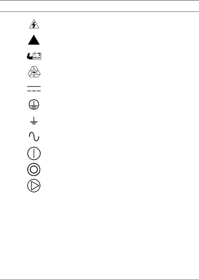
GLOSSARY OF SYMBOLS
Risk of electrical shock
!Indicates caution followed by important instructions
Indicates the unit contains a valve-regulated, lead-acid battery
Recycle
DC voltage
Equipment grounding conductor
Bonded to ground
AC voltage
ON/Alarm Silence/Manual Self-Diagnostic Test
OFF
Status Change Button
3
Introduction
1.0INTRODUCTION
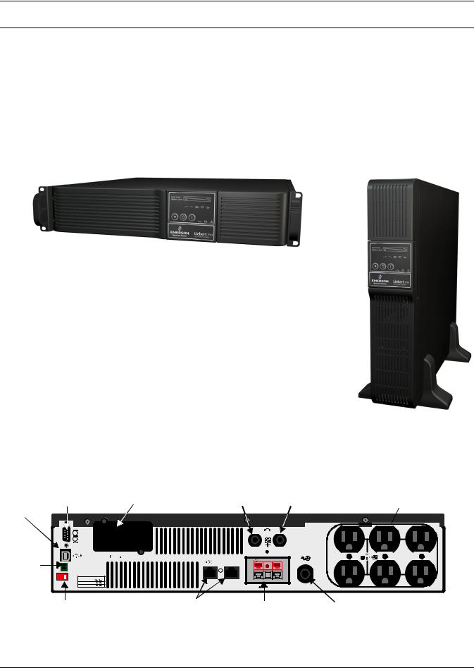
The Liebert PSI™ XR is a 2U, line-interactive UPS that may be installed in a rack or used as a tower UPS.
Status indicators on the front of the Liebert PSI XR display load level, battery level, buck/boost, sitewiring fault, overload, battery status and UPS operation. Controls include a combination On/Alarm Silence/Manual Self-Diagnostic Test button, an Off button and a Status Change button.
The Liebert PSI XR has USB, DB-9 (contact closure) and Liebert IntelliSlot® ports. The DB-9 and USB ports provide detailed operating information including voltages, currents, and alarm status to the host system when used in conjunction with Liebert MultiLink™ software.
The Liebert PSI XR is compliant with the Restriction of Hazardous Substances Directive (ROHS), prohibiting use of six hazardous materials manufacturing of electronics, including lead-free solder.
Figure 1 Front view of UPS
Liebert PSI XR rack-mount configuration Display rotates for use as tower
Liebert PSI XR tower configuration
Display rotates for use in rack
Figure 2 1000 and 1500—rear view
|
DB-9 Port |
Liebert |
Input Circuit Breaker |
Output Circuit Breaker |
|
||
|
(Contact |
IntelliSlot |
(12A for 1000VA; |
(8A for 1000VA; |
Receptacles |
||
|
Closure) |
Port |
15A for 1500VA) |
15A for 1500VA) |
NEMA 5-15R |
||
USB |
|
|
|
|
|
|
|
Port |
|
|
|
INPUT |
OUTPUT |
|
|
|
|
|
|
|
|
||
EPO |
EPO |
|
|
|
|
|
|
|
FUNCTION 2 1 |
|
|
|
|
|
|
|
VOLTAGE=110V |
|
|
|
|
|
|
|
VOLTAGE=120V |
|
|
|
|
|
|
|
VOLTAGE=127V |
|
|
DC 24V |
|
|
|
|
|
|
|
|
|
||
Voltage Configuration |
Network Surge |
External Battery |
Power Cord; 5-15P |
||||
DIP Switch |
Protection |
|
Cabinet Connector |
(not shown for clarity) |
|||
4

Introduction
Figure 3 |
2200—rear view |
|
|
|
|
|
|
|
|
|
|
|
|
|
|
|
|
|
|
||||
|
|
|
|
|
|
15A Output Circuit Breaker |
Receptacles #3 and #4 |
||||||||||||||||
|
|
|
|
|
Power Cord; 5-20P |
for Receptacles #3 & #4 |
|||||||||||||||||
|
|
|
|
|
NEMA 5-15R |
||||||||||||||||||
|
|
|
|
|
|
|
|
|
|
|
|
||||||||||||
DB-9 Port |
(not shown for clarity) |
|
|
|
|
|
|
|
|
|
|
|
|
|
|
|
|
|
|
||||
|
|
|
|
|
|
|
|
|
|
|
|
|
|
|
|
|
|
|
|||||
(Contact |
|
Liebert |
|
Receptacles #1 and #2; |
|
|
|
|
|
|
|
Receptacles |
|||||||||||
Closure) |
|
30A Input |
NEMA 5-20R T-Slot |
|
|
|
|
|
|
|
|
#5 and #6 |
|||||||||||
|
|
|
|
|
IntelliSlot |
|
|
|
|
|
|
|
|
|
|
|
|
|
NEMA 5-15R |
||||
|
|
|
|
|
Port |
Circuit Breaker |
|
|
|
|
|
|
|
|
|
|
|
|
|
||||
|
|
|
|
|
|
|
|
|
|
|
|
|
|
|
|
|
|
|
|
|
|
||
|
|
|
|
|
|
|
|
|
|
|
|
|
|
|
|
|
|
|
|
|
|
|
|
|
|
|
|
|
|
|
|
|
|
|
|
|
|
|
|
|
|
|
|
|
|
|
|
|
|
|
|
|
|
|
|
|
|
|
|
|
|
|
|
|
|
|
|
|
|
|
|
|
|
|
|
|
|
|
|
|
|
|
|
|
|
|
|
|
|
|
|
|
|
|
|
|
|
|
|
|
|
|
|
|
|
|
|
|
|
|
|
|
|
|
|
|
|
|
|
|
|
|
|
|
|
|
|
|
|
|
|
|
|
|
|
|
|
|
|
|
|
|
|
INPUT
EPO |
|
|
FUNCTION |
2 |
1 |
VOLTAGE=110V |
OUTPUT |
VOLTAGE=120V |
|
VOLTAGE=127V |
DC 48V |
|
|
EPO |
|
USB Port |
External Battery |
Cabinet Connector |
Voltage Configuration |
Network Surge |
20A Input Circuit Breaker |
15A Output Circuit Breaker |
DIP Switch |
Protection |
Receptacles #1 and #2 |
for Receptacles #5 & #6 |
Figure 4 3000—rear view
|
|
15A Output Circuit Breaker |
|
||
Power Cord; L5-30P |
|
for Receptacles #3 & #4 |
Receptacles #3 and #4 |
||
|
|
|
|||
(not shown for clarity) |
|
|
|
||
|
|
|
NEMA 5-15R |
||
|
NEMA L5-30R |
|
Receptacles #1 and #2; |
||
Liebert |
30A Input |
Receptacles |
|||
Receptacle |
NEMA 5-20R T-Slot |
||||
IntelliSlot |
|
Circuit Breaker |
|
#5 and #6 |
|
DB-9 Port |
Port |
|
|
|
|
|
|
|
|
|
|
|
NEMA 5-15R |
|||||
|
|
|
|
|
|
|
|
|
|
|
|
|
||||||
|
|
|
|
|
|
|
|
|
|
|
|
|
|
|
|
|||
(Contact |
|
|
|
|
|
|
|
|
|
|
|
|
|
|
|
|
||
Closure) |
|
|
|
|
|
|
|
|
|
|
|
|
|
|
|
|
||
|
|
|
|
|
|
|
|
|
|
|
|
|
|
|
|
|
|
|
|
|
|
|
|
|
|
|
|
|
|
|
|
|
|
|
|
|
|
|
|
|
|
|
|
|
|
|
|
|
|
|
|
|
|
|
|
|
|
|
|
|
|
|
|
|
|
|
|
|
|
|
|
|
|
|
|
|
|
|
|
|
|
|
|
|
|
|
|
|
|
|
|
|
|
|
INPUT
EPO |
|
|
FUNCTION |
2 |
1 |
VOLTAGE=110V |
|
OUTPUT |
|
|
VOLTAGE=120V |
|
|
||
VOLTAGE=127V |
|
DC 48V |
|
|
|
|
|
||
EPO |
|
|
|
|
USB Port |
|
External Battery |
15A Output Circuit Breaker |
|
|
|
|||
|
Network Surge |
Cabinet Connector |
||
Voltage Configuration |
for Receptacles #5 & #6 |
|||
Protection |
|
|||
20A Output Circuit Breaker |
||||
DIP Switch |
|
|||
|
|
Receptacles #1 and #2 |
|
|
5
What’s Included
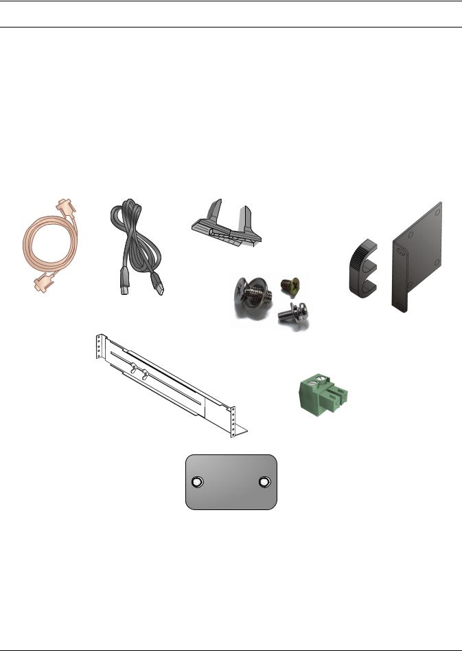
2.0WHAT’S INCLUDED
The Liebert PSI XR is shipped with the following items:
•Multi-Language User Manual on CD
•Liebert MultiLink Software and User Manual, downloadable at multilink.liebert.com
•Contact Closure (ML9P9S) Cable
•USB Cable
•Tower Stands
•Mounting Hardware
•Rack-Mount Handles
•Fixed Mounting Rails
•EPO Connector
•Battery-UPS Tab
Figure 5 Accessories
|
Tower Stands |
|
Contact Closure |
USB cable |
|
(ML9P9S) Cable |
6 ft (1.8m) |
|
6 ft (1.8m) |
|
Rack-Mount |
|
Mounting Hardware |
Handles |
|
|
|
|
(Screws and Washers) |
|
Fixed
Mounting Rails
EPO
Connector
Battery-UPS Tab
6
Loading...