

Page 1
Emerald K3
Engine management system
Operating manual
Draft v0.51
1
Page 2
Map switching
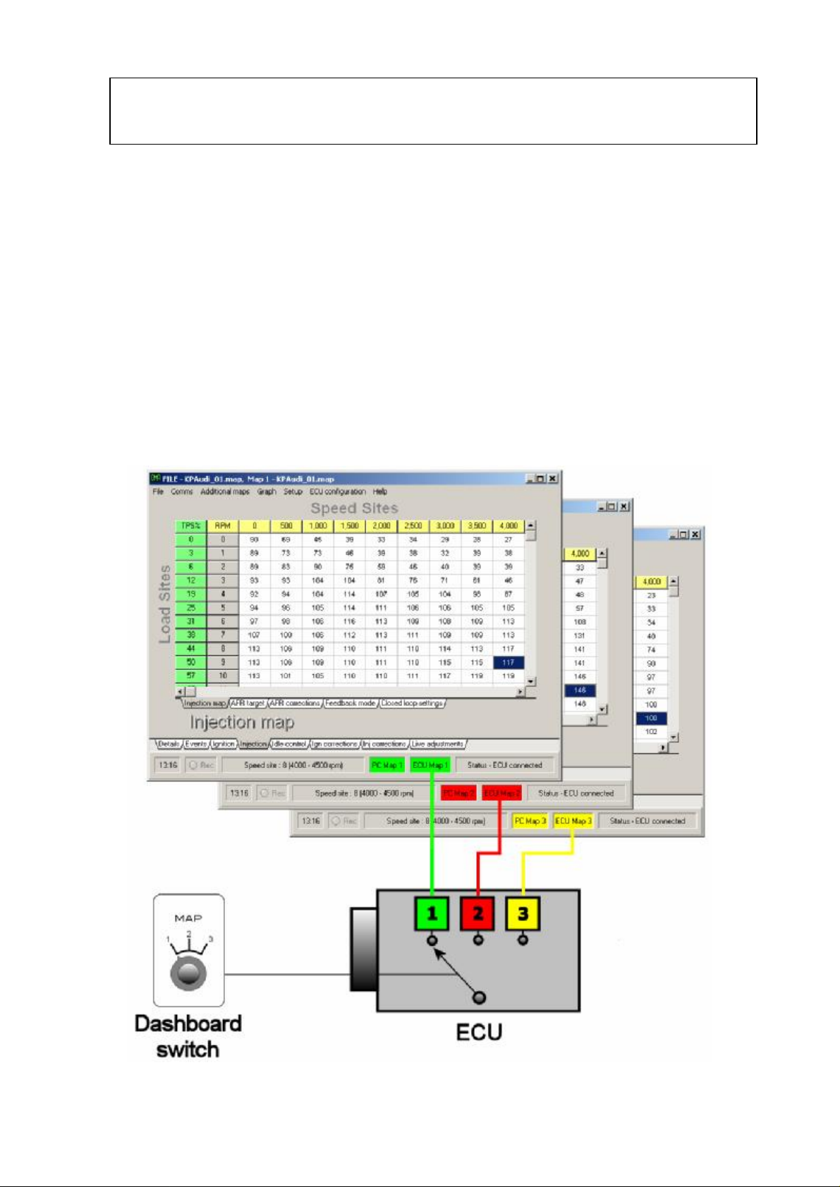
• The ECU can store up to three completely separate maps.
• If set to do so the ECU will allow you to freely switch between maps on-the-
fly.
• The mapping software also holds three maps in memory and will switch maps
in sync with the ECU.
• The mapping software uses a new file format that allows three maps be to
stored within the one file.
• A 0-5 volt signal via an analogue input can be used to instruct the ECU which
map to use. A simple two position on-off switch can be used to provide a
high-low signal that will enable you to switch between two maps. To switch
between three maps a rotary multi-position or potentiometer can be used.
2
Page 3
Map switching – software
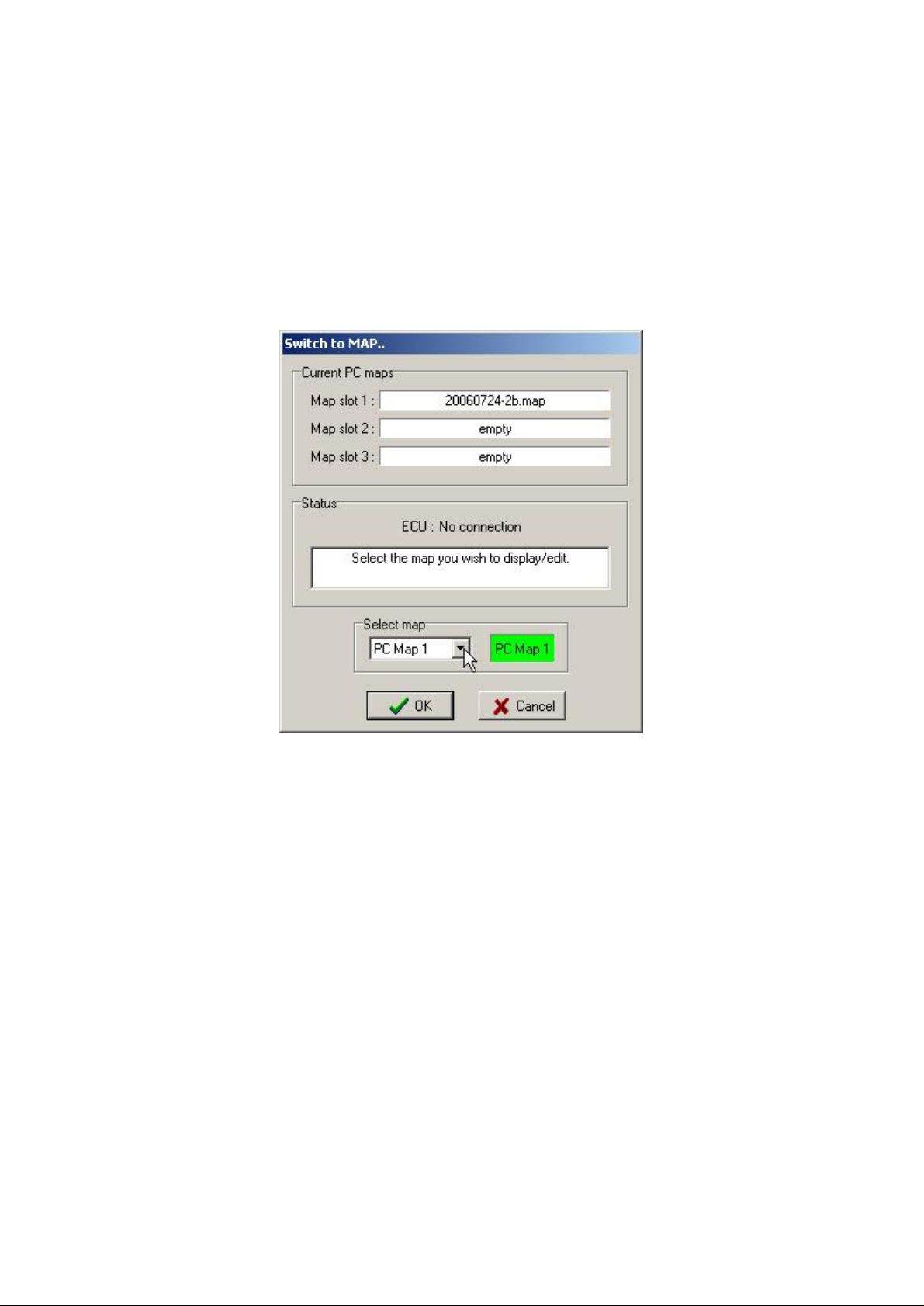
The K3 ECU has the ability to retain three totally separate maps within the ECU. The
laptop or PC also has three map screens available. For as long as the PC is
communicating with the ECU it will automatically switch the maps displayed to stay
in sync. If you want to work on a map that is not currently selected without using the
ECU to switch maps you can power down the ECU (or unplug the communications
lead) and select ‘Switch to map’ from the ‘File’ menu.
There is a short cut to this map selection screen by clicking the PC map box at the
bottom of the main screen.
Note: To prevent confusion the PC will not allow you to switch maps when linked to
the ECU.
For example: if mapping on a rolling road you can alter the fuel and ignition settings
on map 1 (green map) via the live mapping page (F8) and then, via a switch on the
dash, switch to map 2 (red map). The PC will bring the red map to the front of the
screen and you can alter fuel and ignition timing again via the live mapping screen
exactly as before. Switch the ECU to map 3 (yellow map) and repeat the mapping
process.
3
Page 4
Map switching - configuration
There are various ways of setting up the ECU to read the switching signal. Below are
two examples.
Example 1
The ECU is to switch between two maps according to a user activated switch. In this
particular case AuxIn35 is unused so it is available as an input source for the map
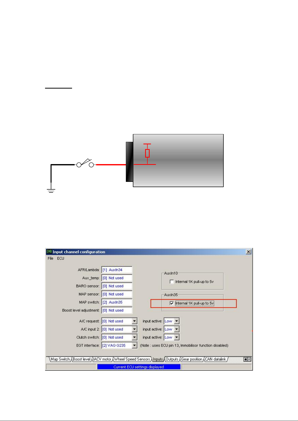
switching function. By enabling the internal pull-up resistor on the AuxIn35 input we
can change maps using a simple switch to earth.
+5v
Map switch
ECU
AuxIn35
With the switch in the open position the internal pull-up resistor results in the ECU
reading 5v at the AuxIn35 input. With the switch in the closed position the ECU will
read 0v at the AuxIn35 input. The internal pull-up to +5v for AuxIn35 must be
enabled in the ‘Input channels’ section of the ‘ECU configuration’ as shown below.
4
Page 5
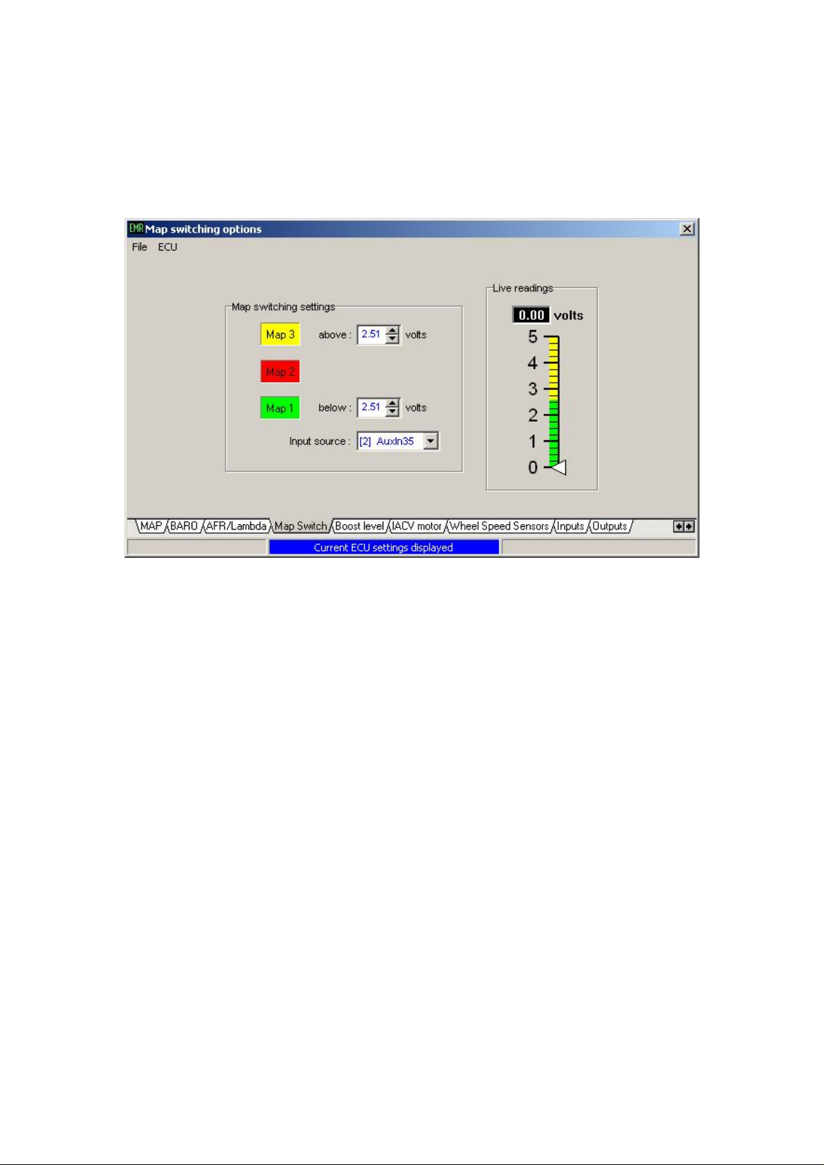
To configure the map switching function select ‘Map switching’ from the ‘ECU
configuration’ menu.
In this example we have two voltage levels, 0v and 5v, at AuxIn35 depending on the
position of a switch.
The input source has been set to AuxIn35. Two voltage levels are used to determine
which map the ECU should be using. Map 1 is selected if the voltage is below a
certain threshold and Map 3 is selected if the voltage is above a certain threshold.
Map 2 is selected if the input voltage lies between the above and the below thresholds.
For this example the mid-point voltage of 2.51 volts is used as the above and below
thresholds. Map 1 is selected if the voltage at AuxIn35 is below 2.51 volts (switch is
in the closed position) and Map 3 is selected if the voltage at AuxIn35 is above 2.51
volts (switch is in the open position). Map 2 is not used and cannot be activated.
When the ECU is connected the live readings panel shows the real-timeinput voltage
used for the map switching function. The bar graph has a vertical scale that presents 0
to 5 volts and is also colour coded to show the voltage to map selection relationship.
The vertical colour coding of the bar graph is colour coded according to the map
switching settings.
5
Page 6
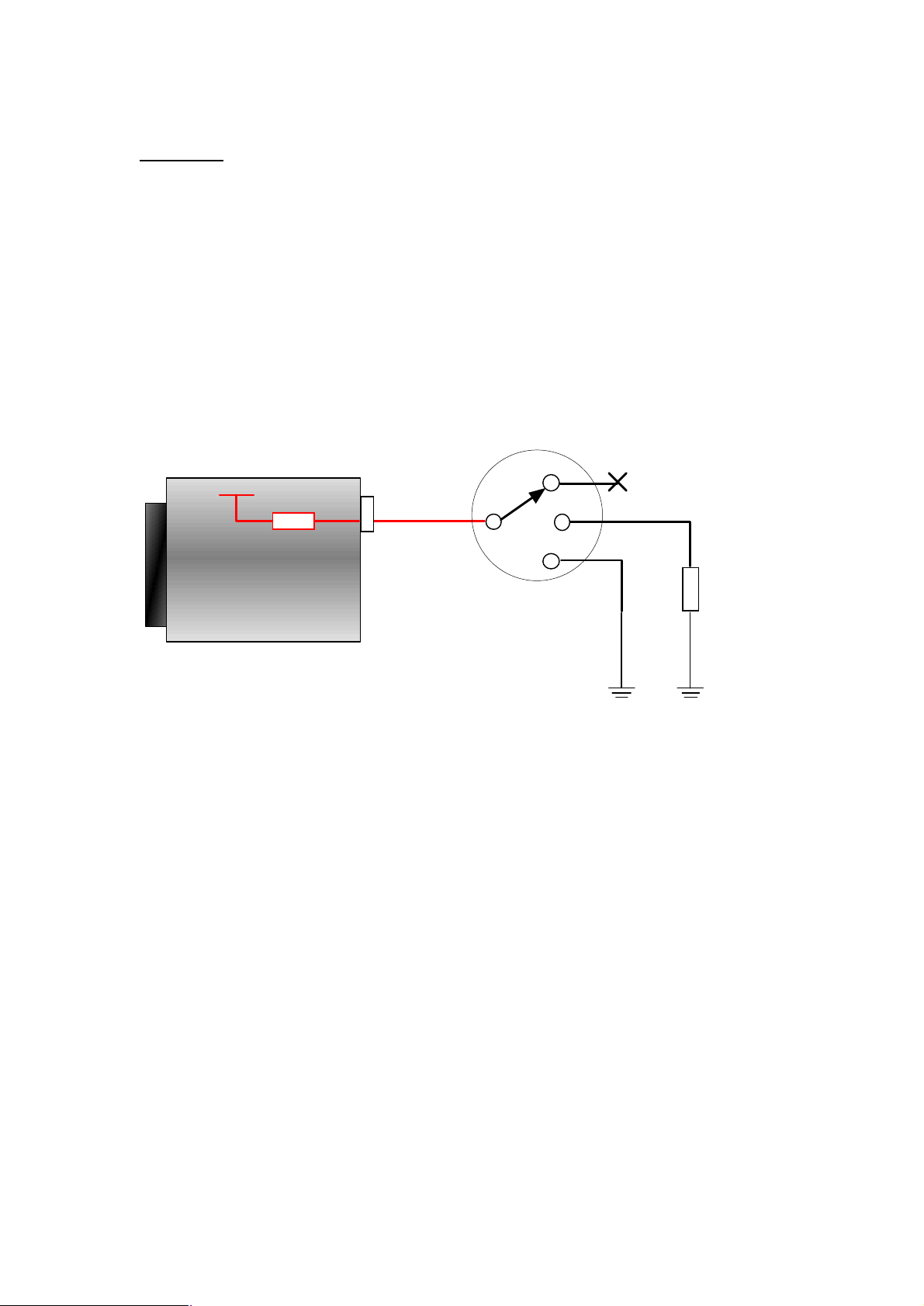
Example 2
The ECU is to switch between the three maps according to a 3-way rotary position
switch mounted on the dash board.
As with the previous example, using an analogue input that has an internal pull-up
resistor simplifies the map switch wiring. Using such an input gives us two voltage
levels with a switch to earth (open = 5 volts, closed = 0 volts). By switching this
input to earth via a resistor we create a potential divider circuit which will result in a
third voltage level of between 0 volts and 5 volts (depending on the value of the
resistor used). As the ECU uses 1KΩ internal pull-up resistors we can switch the
input to earth via another 1KΩ resistor to give a mid-point voltage level of 2.5 volts.
3
+5v
1K
Ω
Aux7b
2
1
1K
Ω
ECU
In this example Aux7b is free so will be assigned to the map switching function.
Aux7b, Aux8b and Aux9b have fixed internal 1KΩ pull-up resistors.
With the rotary position switch at position 1 Aux7b is connected to earth which
results in an input voltage of 0 volts.
At position 2 Aux7b is connected to earth via a 1KΩ resistor resulting in 2.5 volts at
Aux7b.
At position 3 Aux7b is unconnected so will be at 5 volts due to the internal pull-up
resistor.
6
Page 7
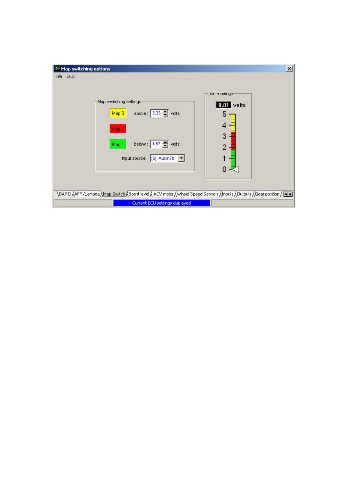
The ECU configuration for this example is shown below.
Here the map switch thresholds have been set so that the boundaries are spaced evenly
give more than enough room for error.
The map switching function monitors the input voltage approximately 5 times per
second. Before changing maps the ECU will re-evaluate the new map according to
the current running conditions to ensure the change is seamless. This process takes
approximately 1- 2mS.
The ECU will switch maps on-the-fly regardless of engine rpm or load.
7
Page 8
Full throttle gear shift (Flat shift)
This function is used to interrupt/reduce engine power so that a fast gear change can
be made without lifting the throttle. Engine power is reduced by retarding the ignition
to a set position. This ignition timing can be negative (After TDC). If turbo-charged,
this retarded ignition timing during a gear change can provide a form of anti-lag.
The flat shift function will be activated if certain user adjustable conditions are met
and a user assigned input is activated.
This flat shift function can be configured according to the gear box type used.
• Sequential gearbox.
The user assigned input can be wired a gear lever movement switch or clutch
switch. The flat shift function can be configured to interrupt power for a
specific amount of time according to the gear selected.
• H-pattern gearbox.
The user assigned input can be wired to a clutch position or pressure switch.
The flat shift function can be configured to interrupt power for as long as the
input is activated, i.e. until the clutch pedal is released.
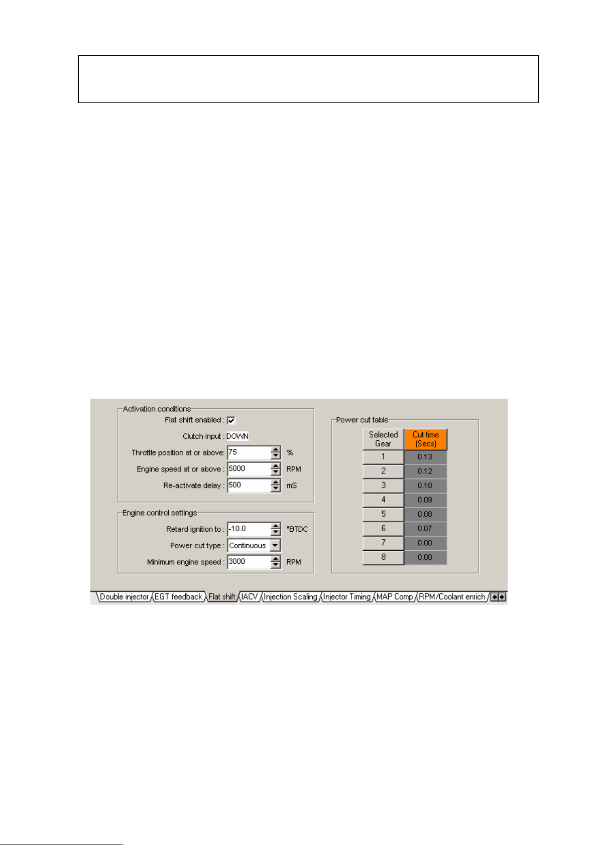
Select ‘full throttle gear shift’ from the ‘Additional maps’ menu to access the settings
page for this function. The settings are grouped into 3 areas on the screen; Activation
conditions, Engine control settings and Power cut table.
8
Page 9
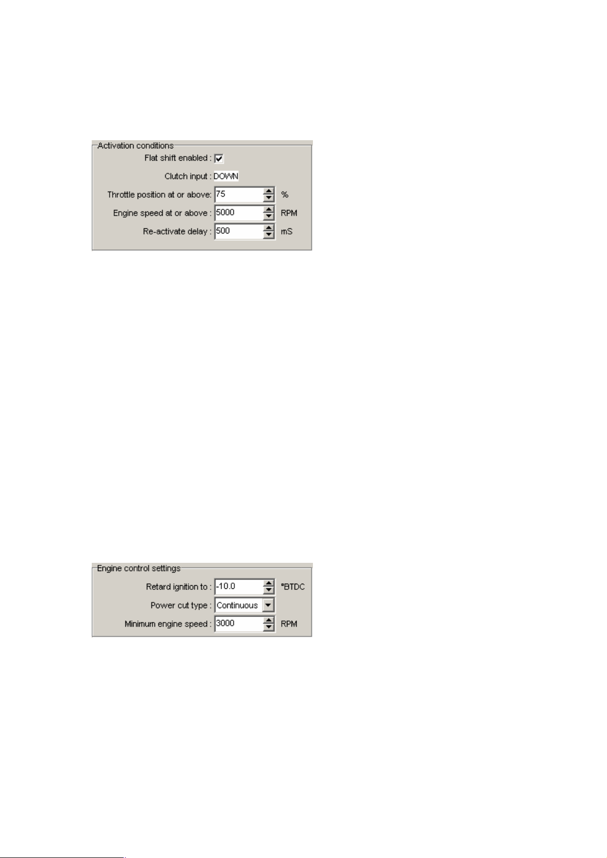
Activation conditions
The activation conditions determine how and when the gear shift function can be
activated.
• Flat shift enabled: Sets whether this function is enabled or not.
• Clutch input: Shows the current clutch switch status .
• Throtte position at or above: Throttle position must be above this before the
flat shift function will activate.
• Engine speed at or above: The flat shift function will only activate above
this rpm.
• Re-activate delay: How long the ECU will wait before allowing
this function to activate again.
Engine control settings
This engine control settings determine how the engine power is cut and how low the
engine rpm is allowed to drop.
• Retard ignition to: Sets the fixed ignition timing during the gear
change. You can retard as far as -30 °BTDC (30
°ATDC).
• Power cut type: Continuous for a power cut for as long as the
input switch is activate or Timed for a timed cut
according to the gear table.
• Minimum engine speed: When activate this function will not allow the
engine rpm to fall below this setting.
9
Page 10
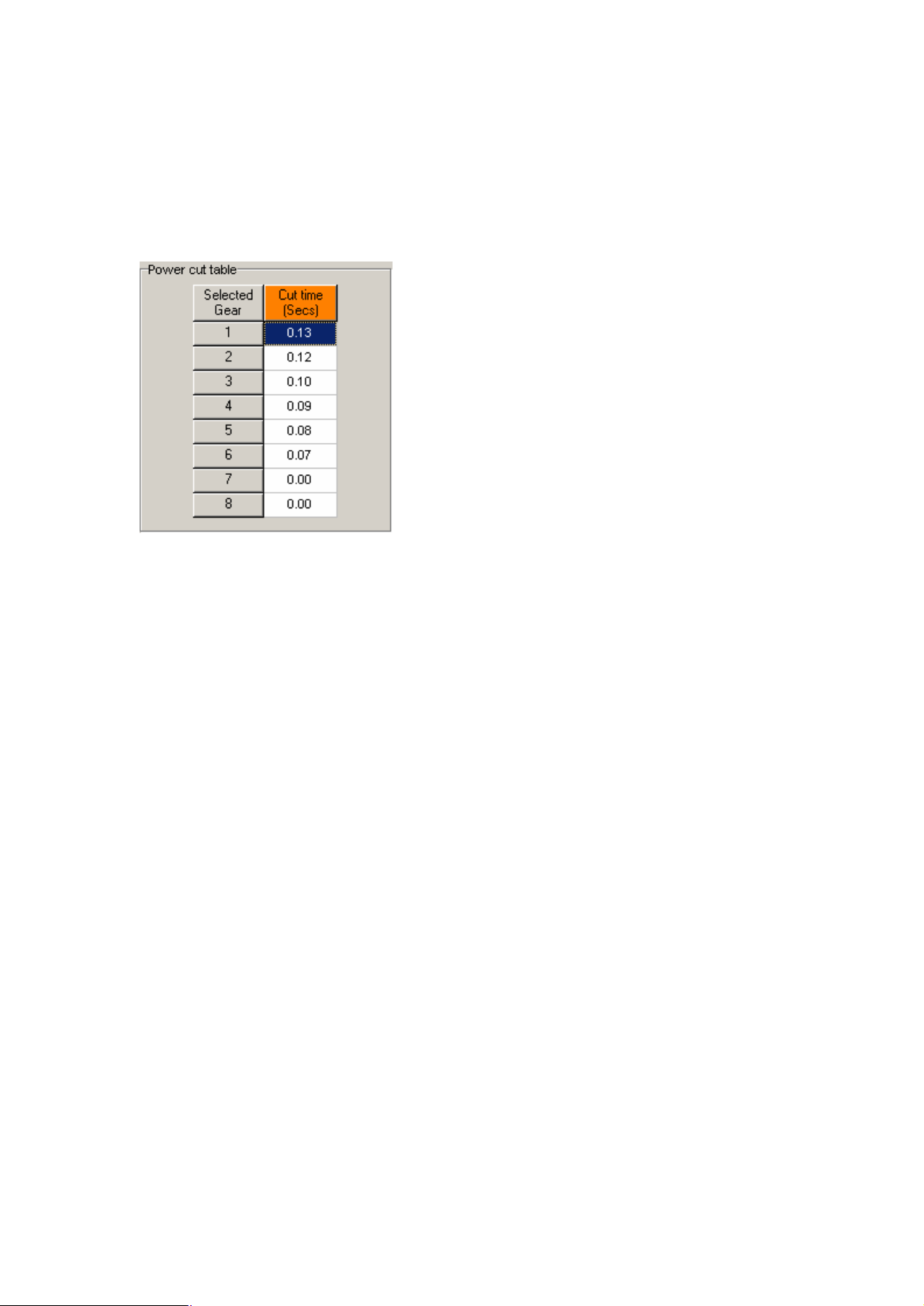
Power cut table
This table is only used when the power cut type is set to ‘timed’. A timed power cut
is usually only used if you have a sequential gear box.
Set the cut time according to the selected gear. If the cut-time is set to zero, the
function will not activate.
10
Page 11
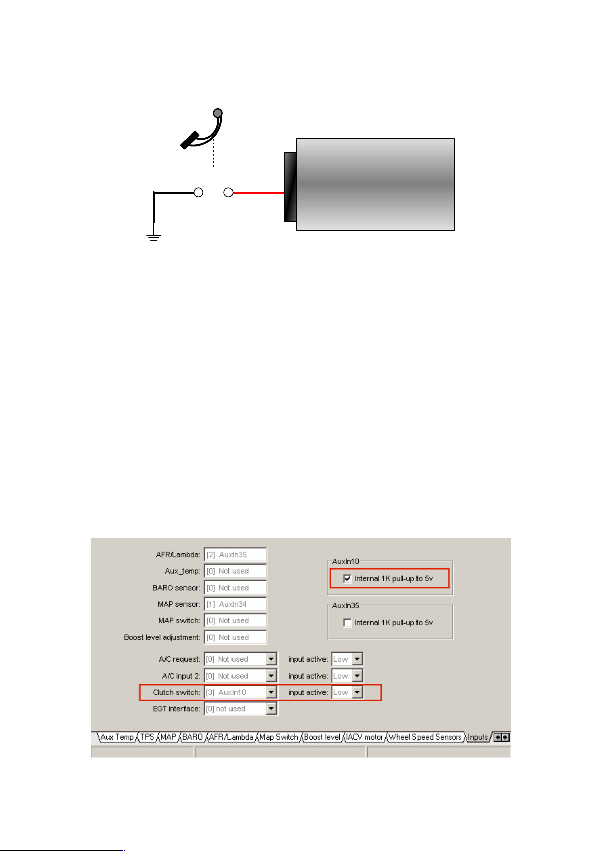
Clutch switch wiring example
Clutch switch
ECU
AuxIn10 (pin 10)
Any spare analogue input can be used to activate the full throttle gear shift function.
This example uses ECU pin 10 (AuxIn10), with the internal pull-up enabled, wired to
a switch on the clutch pedal.
When the clutch pedal is up (not pressed) the clutch switch contacts are open. The
internal pull-up resistor sets the input level ‘high’. When the clutch pedal is down the
switch contacts are closed, the AuxIn10 input is connected to earth which sets the
input ‘low’.
In this example the clutch input is active low, i.e. the signal at AuxIn10 is low when
the clutch is pressed. The ECU should be configured to read AuxIn10 as the clutch
signal and also set to recognise that the clutch is down/pressed when the signal level
is low.
Select ‘Input channels’ from the ‘ECU configuration’ menu. As shown below, the
clutch switch channel has been set to AuxIn10, the input active has been set to Low
and the internal 1K pull-up to 5v has been enabled. ECU inputs AuxIn10 and
AuxIn35 have switchable internal pull-up resistors. If another input connection where
to be used instead, e.g. AuxIn34 or AuxIn36, an external pull-up resistor would need
to be fitted. The AuxIn7b, AuxIn8b and AuxIn9b inputs have internal pull-ups.
example clutch switch configuration settings
11
Page 12
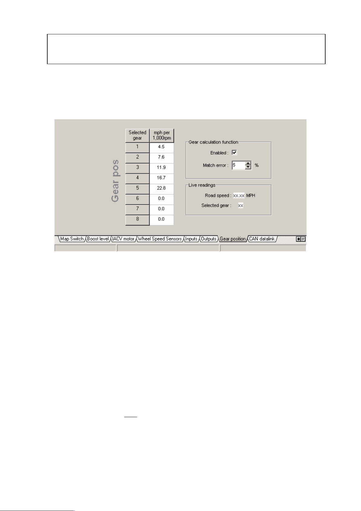
Gear position
The ECU is able to calculate the selected gear by using engine rpm, road speed and a
gear position look-up table.
Select ‘Gear position’ from the ‘ECU configuration’ menu to access the gear position
calculation settings…
Gear calculation function
• Enabled: Sets whether this function is enabled or not.
• Match error: Sets how close the ECU’s calculations must be to the
figures set in the gear pos table.
Gear pos table
For each of the forward gears set the speed (mph/kmh) per 1,000rpm in the table.
The easiest method to determine these values is to set the PC data logger to record
engine rpm and road speed. Drive for a short amount of time in each gear and then
use the data logger trace to determine the table settings.
For example in 3rd gear, at a road speed of 38.0mph, with an engine speed of
3,193rpm :-
Mph per 1,000rpm = __38.0__ x 1000 = 11.9
3193
Note: gear position calculations are suspended while the clutch switch input is active
(clutch = down). If a clutch switch is not fitted ensure that input is disabled.
12
Page 13
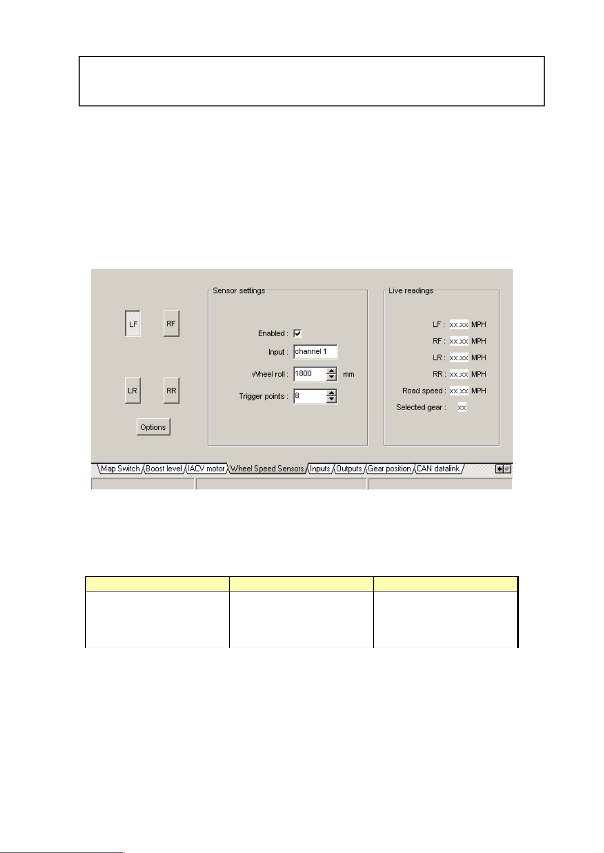
Road speed measurement
The ECU has 4 wheel speed (frequency measurement) input channels via Aux port B.
These input channels can be wired directly to inductive wheel speed sensors or a
digital speed signal.
For speed measurement only one wheel speed signal is needed. If this measurement
is used to calculate the selected gear the signal must be from a driven wheel.
Select ‘Wheel Speed Sensors’ from the ‘ECU configuration’ menu to access the
wheel speed sensor settings.
The four wheel speed input channels are identified as follows
Input Label Aux Port B pin number
Channel 1 LF (Left Front) 2
Channel 2 RF (Right Front) 3
Channel 3 LR (Left Rear) 4
Channel 4 RR (Right Rear) 5
13
Page 14
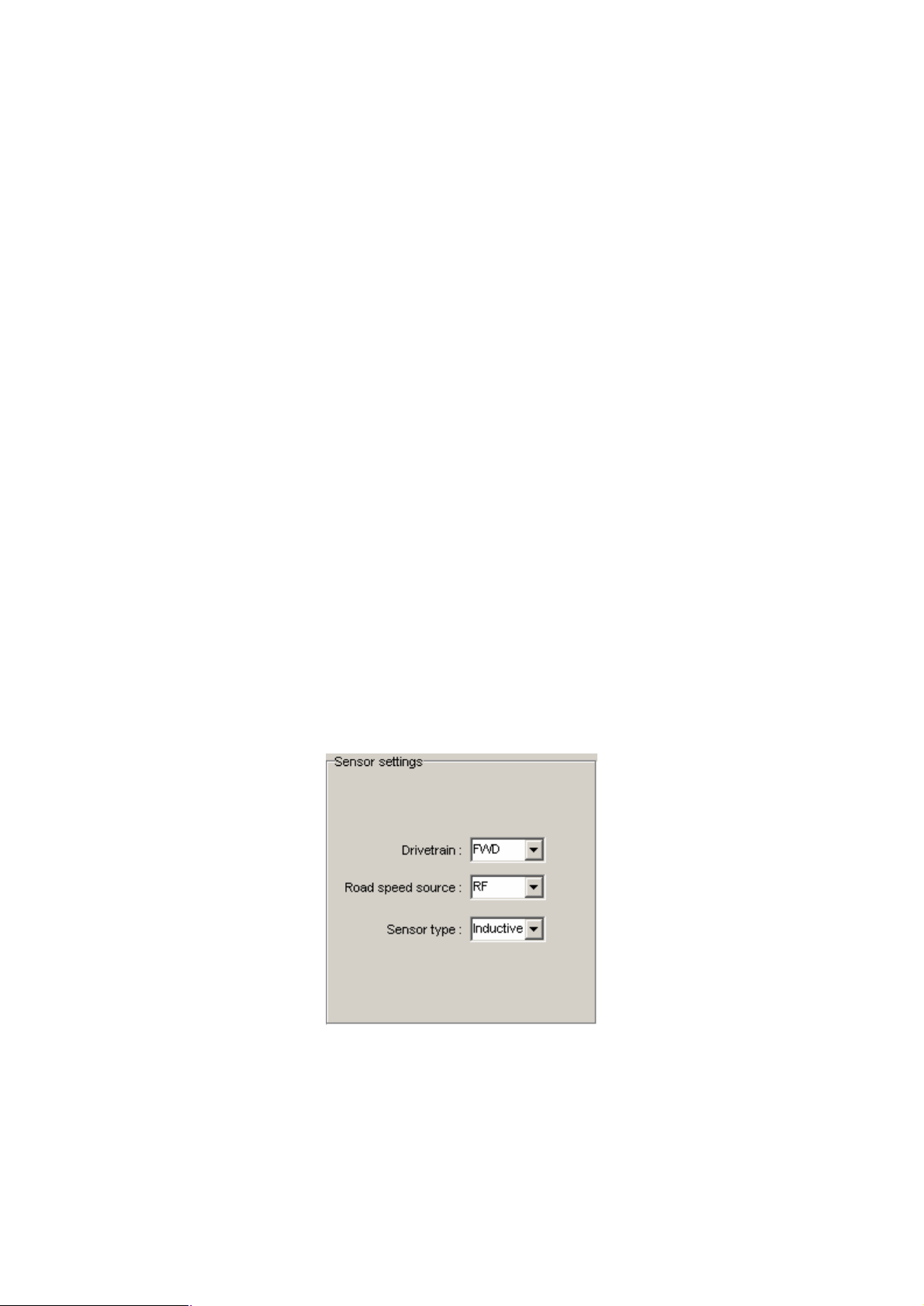
LF, RF, LR, RR sensor settings
Each channel is enabled and configured independently from the other channels. This
flexibility allows differing wheel sizes and/or sensor set ups on each of the four
wheels.
Click the label button (LF, RF, LR, RR) to access the settings for that input channel.
Each channel has the following settings :
• Enabled: Tick the enable box if this channel is used.
• Wheel roll: Distance travelled for one rotation of the wheel.
• Trigger points: Number of pulses per wheel rotation
The trigger points setting can be determined by counting the number of teeth/points
that will pass the wheel speed sensor in one revolution of the wheel.
A quick/simple method to determine the wheel roll setting is to put a chalk mark at
the bottom of the tyre (at the 6 o’clock position) and mark the ground at the same
point. Roll the car forwards so the wheel rotates once and mark the ground in line
with the tyre mark. The distance between the two ground chalk marks, in mm, is the
‘wheel roll’. A rolling road can be used to compare actual and measured road speeds
- adjust the wheel roll value if necessary.
Options
• Drivetrain: This setting is not currently used.
• Road speed source: Set to the channel you wish to measure road speed from
• Sensor type: Global setting for wheel speed sensors, inductive or
digital. Open collector digital sensors will require a
pull-up resistor.
14
Page 15
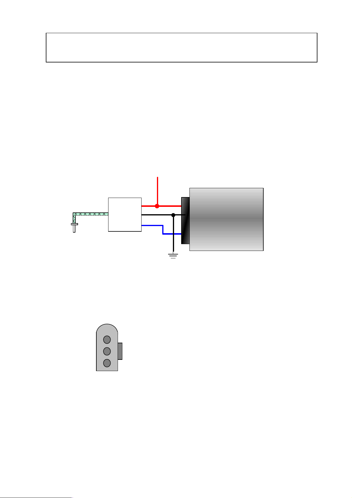
Exhaust Gas Temperature
The Emerald K3 is able to read EGT via an external signal conditioning unit. To
ensure the best accuracy the exhaust gas temperature reading is transmitted digitally
between the signal conditioning unit and the ECU.
The VAG G235 exhaust gas temperature interface combines a thermocouple probe,
suitable for pre-turbo gas temperature measurements, along with a combined
amplifier and serial data output. The serial data output line from the G235 should be
wired to ECU pin 13.
+12v supply
thermocouple
probe
3
2
1
EGT interface
VAG
G235
3
2
1
pin 28
pin 29
pin 13
ECU
VAG G235 to Emerald K3 connection diagram
Wire side of G235 loom connector
15
Page 16
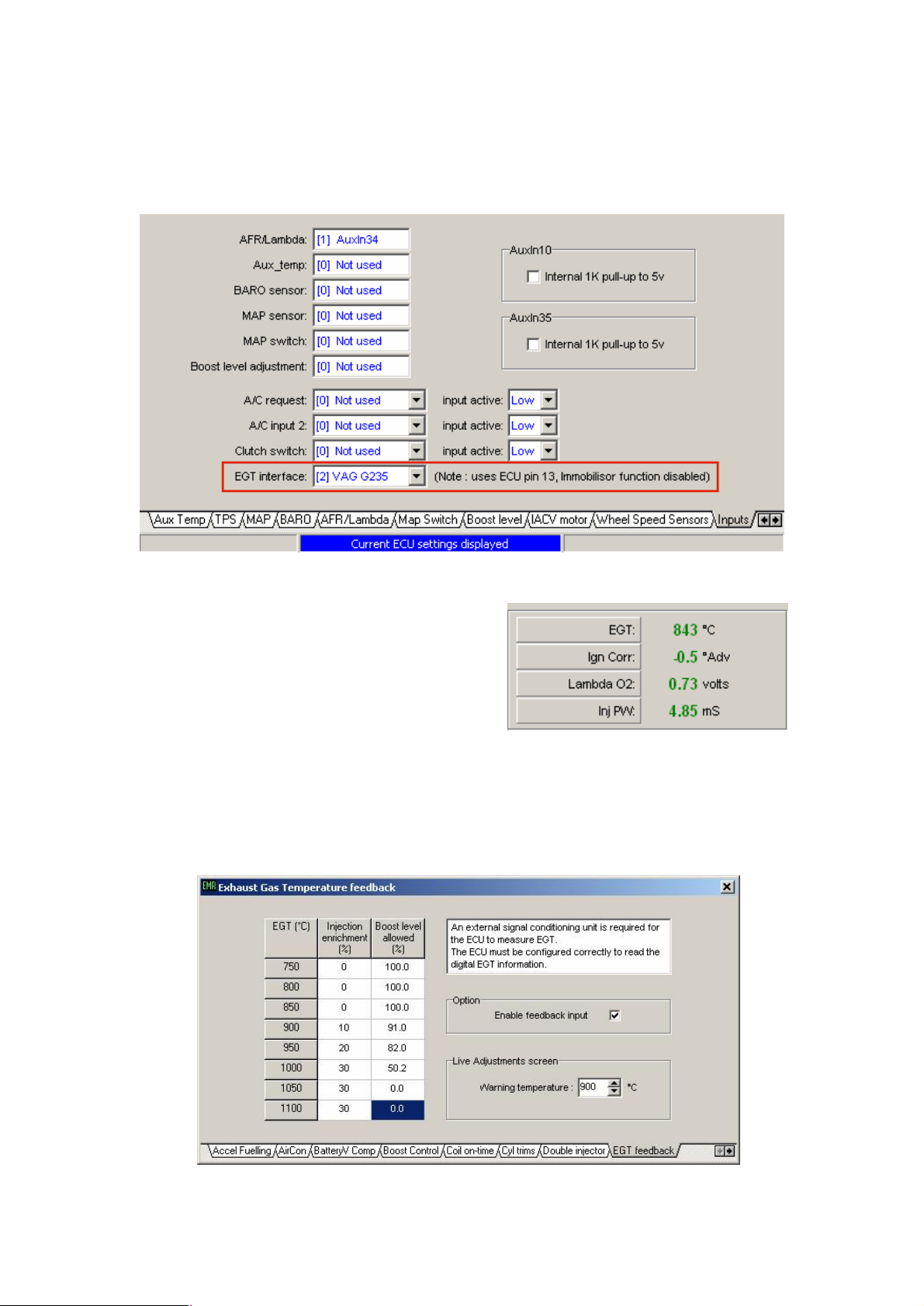
To set the ECU to read the G235 exhaust gas temperature serial data the ‘EGT
interface’ setting in the ‘Input channels’ section of the ECU configuration should be
to ‘[2] VAG G235’ as shown below..
Once configured to read EGT from the G235
this EGT measurement can be displayed on the
‘live adjustments’ screen. This EGT reading
can also be recorded, along with other
readings, into the data-logger.
The EGT can be used, in conjunction with the feedback table, to adjust the fuelling
and/or boost pressure.
16
Page 17
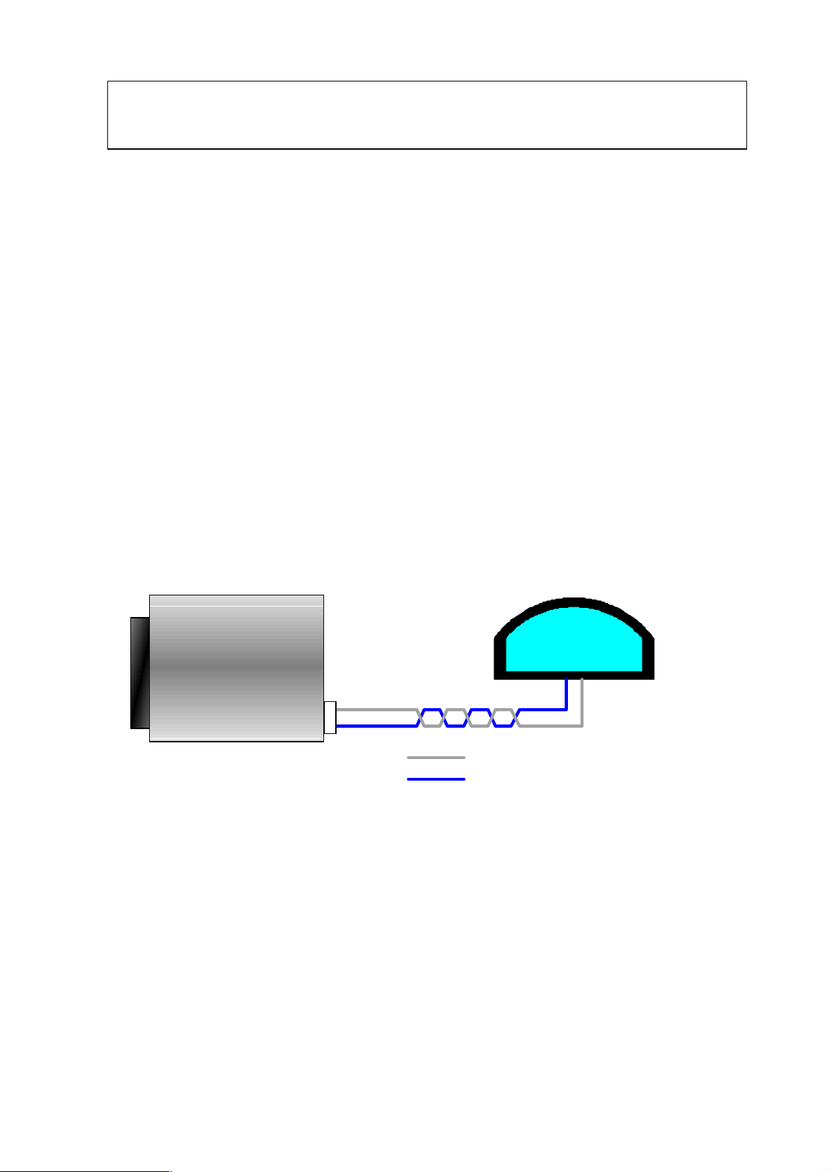
CAN data-link
The K3 ECU can be configured to set transmit data to external devices, such as
dashboards, using it’s Controller Area Network interface.
The CAN was originally developed by Bosch Gmbh as a robust serial
communications protocol to pass information between controllers on an automotive
network. Communication speeds can be up to 1 Mbit/s between multiple devices
sharing the same 2-wire CAN bus.
The CAN bus wiring should be a twisted-pair cable and, if required, shielded. The
CAN bus must be terminated at each end by a 120Ω resistor. The K3 ECU, with it’s
internal 120Ω termination resistor, provides one end of the CAN bus. When
connecting another device/s you must ensure that the CAN bus is correctly terminated
with another 120Ω resistor. This termination resistor must be at the other end of the
CAN bus. Some devices (e.g. the AIM MXL dash logger) also have an internal
termination resistor so an external resistor is not required.
AIM dash logger connection
ECU
AIM
1
COMMS
2
CAN_H
CAN_L
Refer to the ‘Communications port’ section of the manual for further details of the
communications port.
17
Page 18
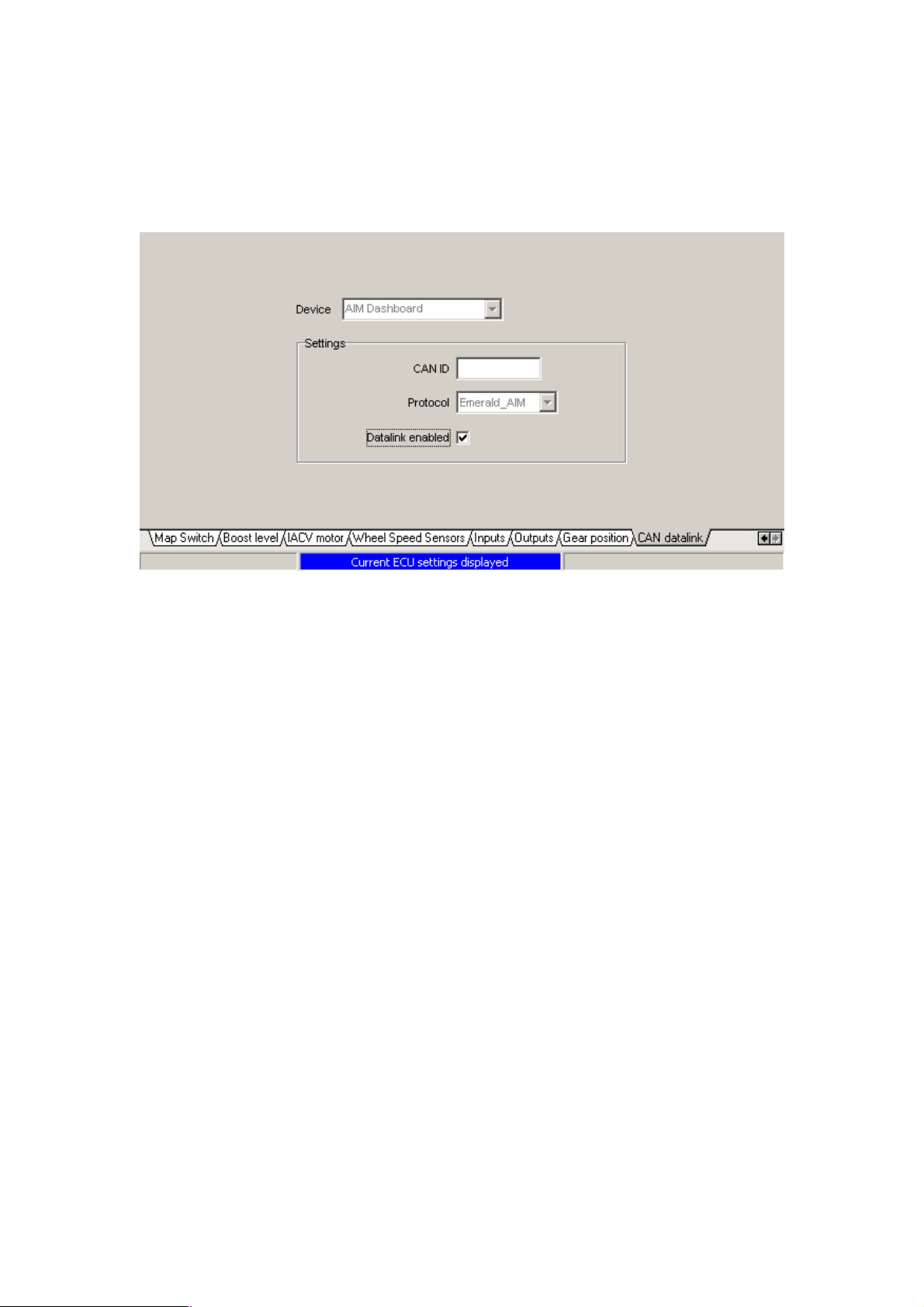
K3 CAN configuration
Select ‘CAN data-link’ from the ‘ECU configuration’ menu.
From the ‘Device’ drop down menu select ‘AIM dashboard’. To enable this K3 to
AIM data-link ensure the ‘data-link’ check box is ticked.
Before configuration changes can take effect the ECU must be updated, select
‘Update ECU configuration’ from the ‘ECU’ menu.
AIM MXL configuration
Using the AIM Race Studio 2 software select ‘System manager’.
Retrieve the current configuration from the AIM dash by clicking the ‘Receive’
button. Click the ‘ECU manufacturer’ entry for the current configuration and set to
‘AIM’. Click the ‘ECU model’ entry for the current configuration and set to
‘PROT_CAN’.
If you wish to change how/what data from the ECU is displayed on the AIM dash
click the ‘System configuration’ tab and set accordingly. Once you are happy with
your channel / display settings update the AIM dash by clicking the ‘Transmit’ button.
Refer to your AIM manual for detailed information.
18
Page 19
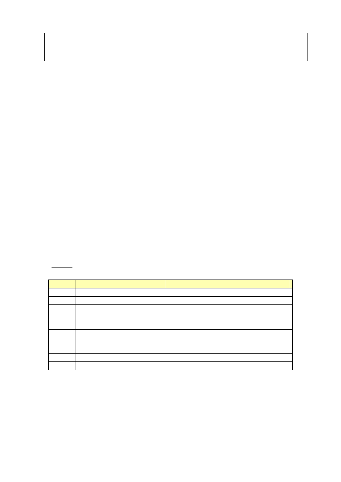
Connection to a wideband lambda
Although the K3 cannot directly control a wideband lambda sensor it can read a 0-5v
analogue signal that relates to AFR/lambda. Many wideband lambda sensor
controllers produce a 0-5v signal for use with ECU’s or data-loggers.
This AFR data can be recorded in the Emerald data-logger, displayed in the live
adjustments screen and used by the ECU for closed loop and/or adaptive fuelling
functions.
The 0-5v signal is converted to AFR by a user adjustable look-up table in the ECU
configuration. This table must be set to match the AFR/voltage of your lambda signal
conditioning unit.
Emerald K3 to Innovate LC-1 connection example
An Innovate LC-1 is used in this example but the principles can be applied to many
other wideband lambda controllers.
The Innovate LC-1 manual should be read carefully before installation.
It is absolutely essential that the correct sensor calibration routine is followed - this is
detailed in the Innovate manual.
Wiring
LC-1 Function Wire to..
Red +12v supply Ignition controlled +12v
Blue Heater ground Good chassis ground or battery (-) terminal
White System ground Join with Green wire to ECU pin 30
Yellow
(narrow band lambda signal)
Brown Analogue out 2
Green Analogue ground Join with White wire to ECU pin 30
Black Calibration wire Calibration button
Analogue out 1
(AFR signal)
ECU pin 7 via inline resistor.
See note 1
Any spare analogue ECU input via an
inline resistor. (see note 2). AuxIn35
(ECU pin 35) is used in this example.
19
Page 20
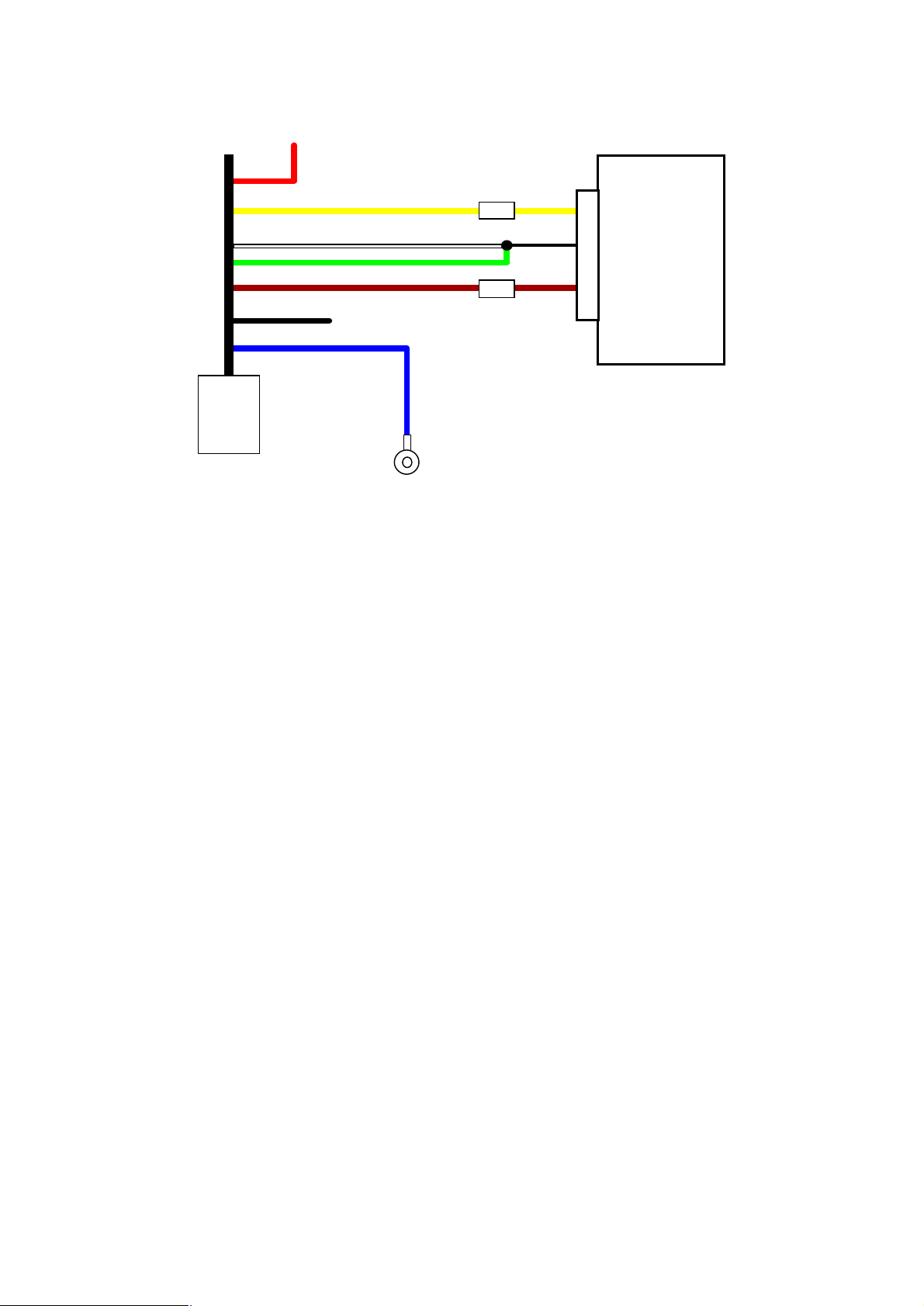
Switched +12v supply
LC-1
To calibration switch
100Ω
100Ω
7
30
35
Emerald
K3
Earth
Note 1:
Narrow band lambda signal. This connection is optional. If used ensure the LC-1 is
set to output a 0-1v narrow band simulated signal on analogue 1. The LC-1 is
normally set to do this by default. A 100Ω resistor* should be fitted inline between
the yellow analogue out 1 wire and the ECU pin 7.
Note 2:
Wide band AFR signal. A 100Ω resistor* should be fitted inline between the brown
analogue out 2 wire and the ECU analogue input pin (AuxIn35, pin 35 in this
example)
*The LC-1 outputs are quite sensitive and can become unstable if connected to a
capacitive load. The inline resistor buffers the LC-1 from the ECU input signal
filters.
20
Page 21
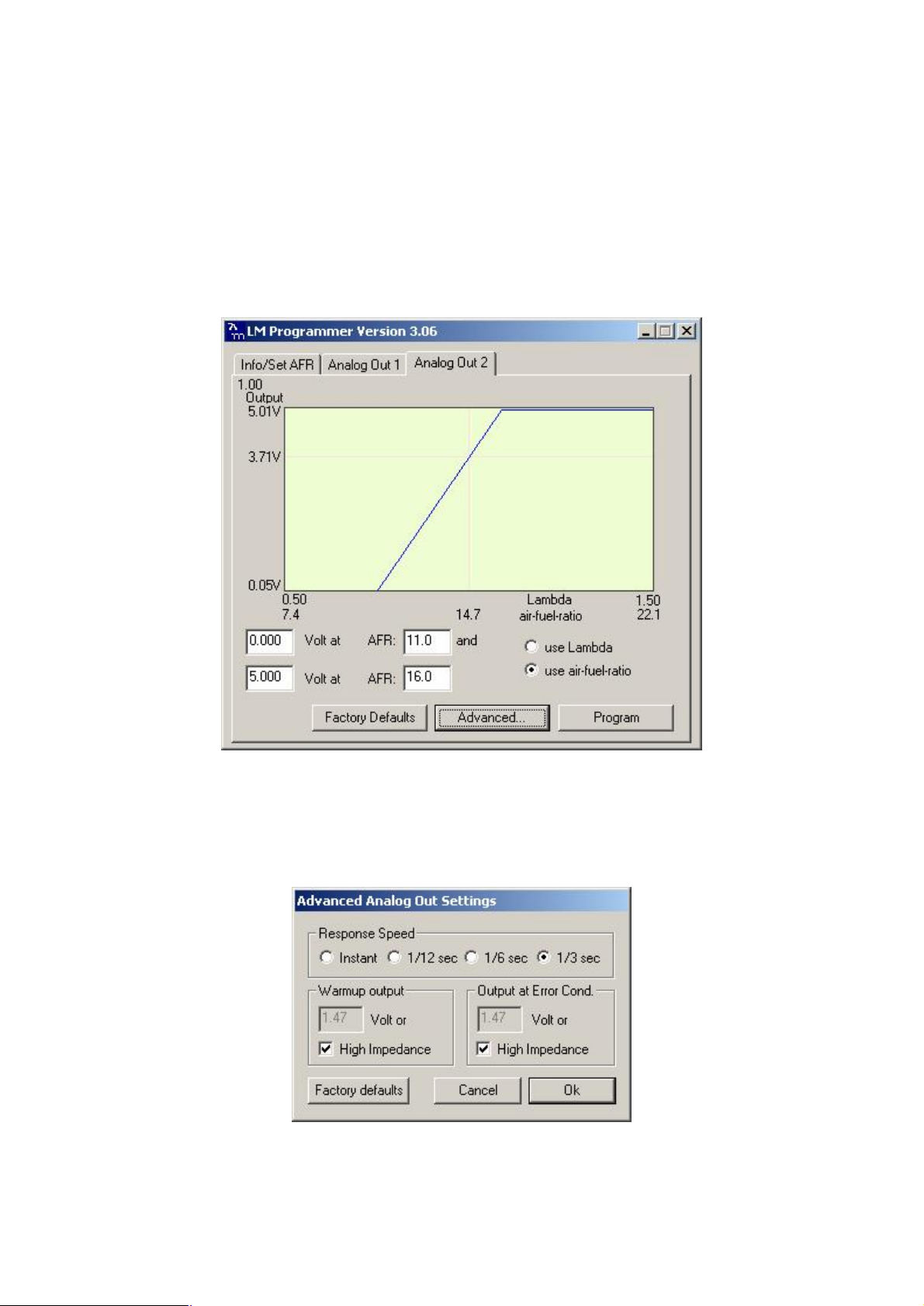
LC-1 configuration
The LC-1 output configuration should match the Emerald K3 input configuration.
We recommend narrowing the AFR range so the 0-5v signal spans a more useful
11.0:1 to 16.0:1. Doing this will mean any noise or voltage offset errors have less of
an impact on the AFR readings.
If the AFR signal appears to be noisy you may find setting the LC-1’s output response
speed to ‘1/3 sec’ helps…
21
Page 22
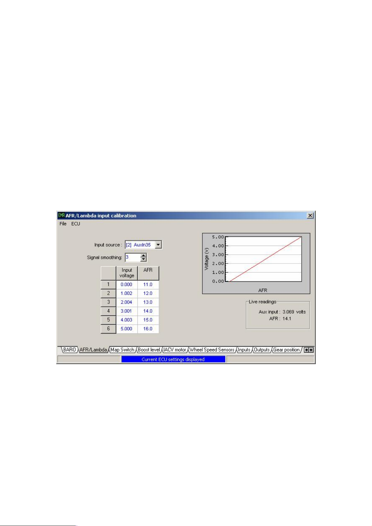
K3 AFR/Lambda input calibration
Any spare analogue input on the ECU can be used to read the LC-1 analogue AFR
signal. AuxIn35 is often spare and is used for this example.
To convert from a voltage to an AFR value a look up table is used.
This table is accessed via the ‘AFR/Lambda input’ page of the ‘ECU configuration’.
Select the input source to suit the analogue input you wish to use and set the table to
match the LC-1 output as shown below.
The ‘live readings’ box will show the current voltage and AFR conversion readings
but note that the AFR readings will not be correct until the ECU has been updated
with the new table settings.
22
Page 23
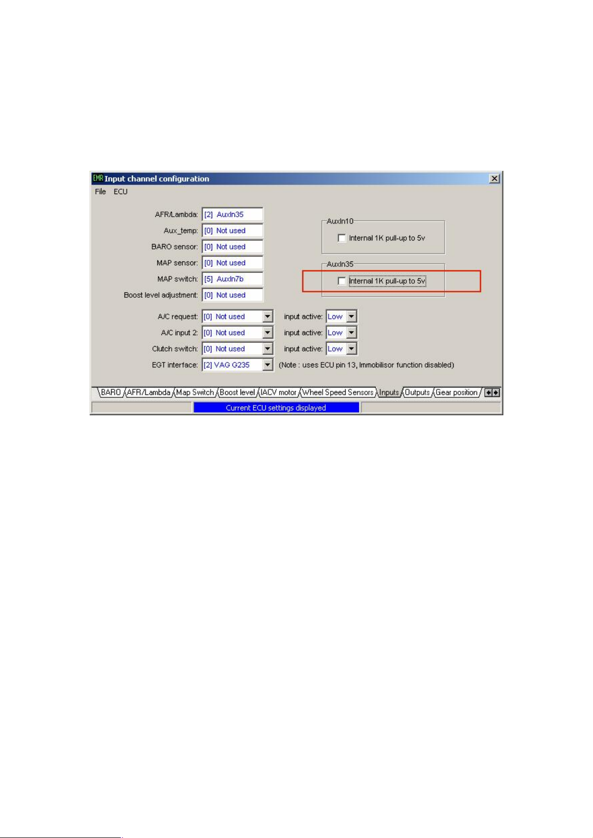
AuxIn10 and AuxIn35 analogue inputs have switchable internal pull-up resistors. As
we have used AuxIn35 in this example you must ensure that the pull-up resistor is
switched off otherwise the analogue AFR signal will be distorted.
From the ‘inputs’ page of the ‘ECU configuration’ screen ensure that the pull-up for
the used input is switched off.
The ‘inputs’ screen confirms that the AFR/Lambda input has been set to AuxIn35 and
that the AuxIn35 internal pull-up is switched off.
Update the ECU with these new settings by clicking ‘Update ECU configuration’
from the ‘ECU’ drop down menu.
The AFR information will now be displayed in the ‘Live adjustments’ screen as an
LED bar display and in numerical form to the right of this.
The data-logger channel can also be set to record this AFR data by selecting
‘AFR/Lambda’ in the data-logger options screen.
23
Page 24
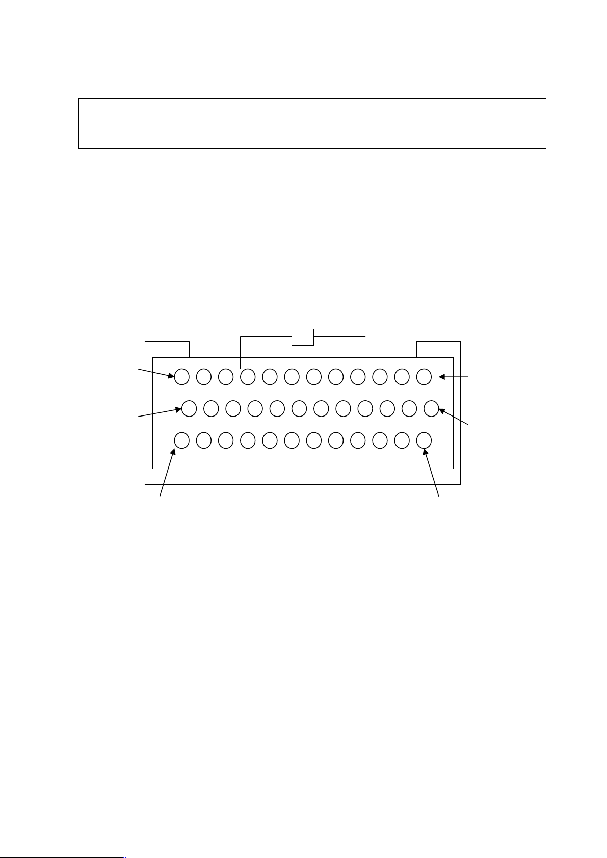
12 13
K3 36-way loom connector
25
36
24
1
Rear view of connector
(wire side)
24
Page 25

Pin
no.
1 Injector driver 4 / AuxOut1 Injector driver 4 or user assigned output
2 IACV2 / AuxOut2 IACV stepper motor channel 2 or user assigned
3 IACV1 / IACV-PWM /
4 Ignition driver 3 / Main Relay
5 Ignition driver 2 / AuxOut5 Ignition driver 2 or user assigned output
6 Cooling fan relay control Output switches to earth to activate relay & fan
7 Oxygen sensor signal input 0-1v input from narrow band sensor
8 Throttle pot signal input 0-5v input from throttle position sensor
9 +5v sensor supply 5v output, 100mA max
10 AuxIn10 User assigned 0-5v input. An internally switched
11 Ignition sense input +12v supply via ignition switch
12 Tacho output signal 0-12v pulsed output
13 Immobilisor/EGT digital input Digital input from a Lucas 5AS immobilisor or
14 +8v sensor supply +8v supply for external sensors
15 Cam phase or custom input Cam sensor input (if required)
16 Air temperature signal input NTC temperature sensor input
17 Injector driver 5 / Ignition
18 Oxygen sensor signal earth
19 Shift-light driver / AuxOut19 Shift-light output (switched earth) or user assigned
20 Fuel pump relay driver Switched earth
21 Injector driver 6 / AuxOut3 Injector driver 6 or user assigned output
22 IACV3 / AuxOut22 IACV stepper motor control or user assigned output
23 Injector driver 2
24 Injector driver 1
25 Ignition driver 1
26 Injector driver 3 / AuxOut26 Injector driver 3 or user assigned output
27 IACV 4 / AuxOut27 IACV stepper motor control or user assigned
28 +12v Ignition supply Supply from main relay or common with pin 11
29 ECU earth Good earth (direct to battery)
30 Sensor earth Common earth for air, coolant & throttle sensors
31 Main trigger signal input Crank sensor or digital distributor input signal
32 Main trigger sensor earth Earth return for main/cam trigger sensors
33 Coolant temp signal input NTC temperature sensor input
34 AuxIn34 User assigned 0–5v input
35 AuxIn35 User assigned 0-5v input. An internally switched
36 AuxIn36 / AuxOut36 User configurable input or output pin
Connection Comments
outputt
IACV stepper motor channel 1, IACV pwm control
AuxOut3
Control
driver 4 / AuxOut17
or user assigned output
Ignition driver 3 or main relay control output
according to ECU configuration
supply for sensors such as TPS, MAP, etc
pull-up resistor can be enabled on this input.
VAG EGT sensor interface
Injector driver 5, Ignition driver 4 or user assigned
output according to ECU configuration
output according to ECU configuration
pull-up resistor can be enabled on this input for
temperature sensors.
Note : Apart from the Tacho output, all ECU driver outputs are switched earths
25
Page 26
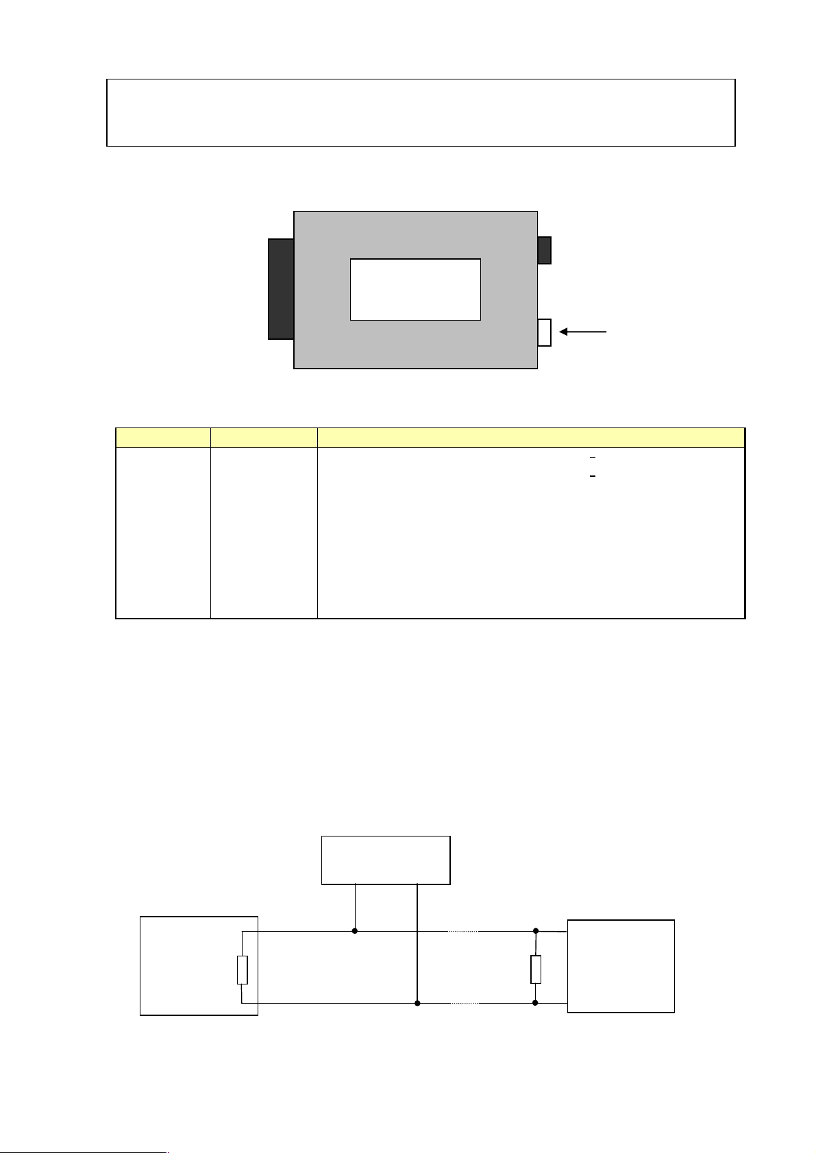
120
CAN
CAN device
Communications port
EMERALD K3
Pin number Connection Comments
1 CAN_H CAN bus interface1
2 CAN_L CAN bus interface1
3 - Not used
4 - Not used
5 earth Signal earth
6 - Not used
7 Rx RS232 serial interface, data receive
8 Tx RS232 serial interface, data transmit
9 CTS RS232 serial interface, clear to send
Comms
Notes:
1. The CAN bus must be terminated with two 120 Ohm resistors. The ECU’s
CAN interface includes a 120 Ohm internal termination resistor.
When connecting devices to the CAN bus confirm that the external CAN
bus is terminated with a 120 Ohm resistor (either an external 120 Ohm
resistor or by a device that has an internal terminating resistor). See
example below…
e.g. data-logger
CAN_H
ECU 120
Ohm
Ohm
CAN_L
Device
e.g. dashboard
26
Page 27
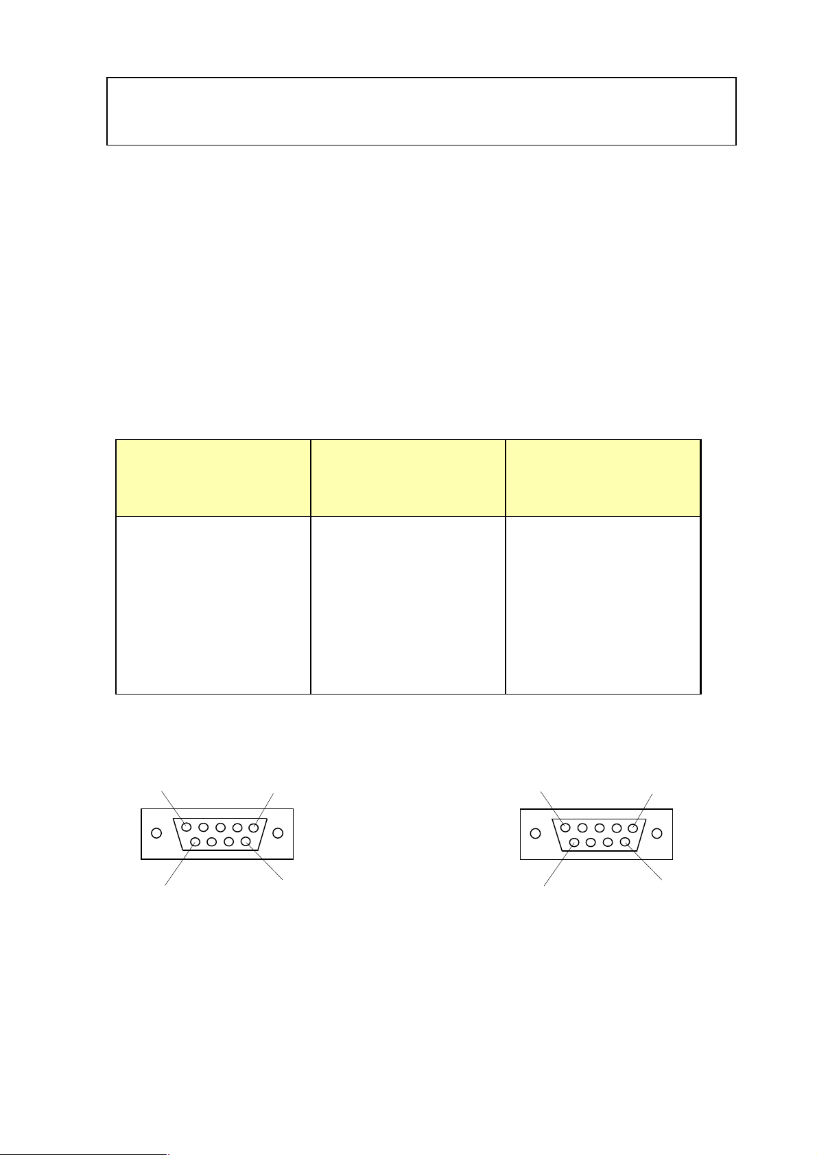
Emerald serial communications lead
The serial communications lead for connection to the PC is NOT a standard a
standard RS-232 serial lead.
Warning: Use of a standard RS-232 lead could lead to damage of either the PC or
ECU.
A serial communications lead is supplied with each ECU at no extra charge. The lead
information is included below if you wish to repair / extend or construct a new lead.
PC
9-way D-type
Wire colour ECU
9-way D-type plug
socket
2 Yellow 8
3 White 7
5 Black 5
8 Red 9
Cable shield not
connected
- Cable shield
soldered to outer
casing
1 5 5 1
6 9 9 6
cable side of PC comms lead socket cable side of ECU comms lead plug
27
Page 28
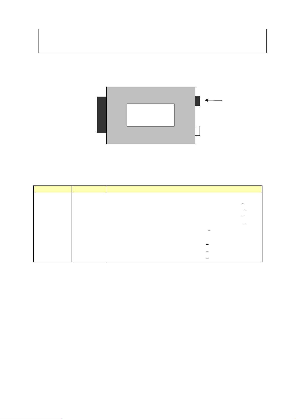
Aux input, port B
Aux input
Port B
EMERALD K3
Pin number Connection Comments
1 Earth Common earth point for wheel speed sensors / switch inputs
2 WSS_LF Signal input from Left Front wheel speed sensor 1
3 WSS_RF Signal input from Right Front wheel speed sensor 1
4 WSS_LR Signal input from Left Rear wheel speed sensor 1
5 WSS_RR Signal input from Right Rear wheel speed sensor 1
6 Status_LED LED control output. 2
Direct anode connection (no current limit resistor needed)
7 AuxIn7b Level switch input 3
8 AuxIn8b Level switch input 3
9 AuxIn9b Level switch input 3
Notes:
1. Wheel speed sensor input signals can be analogue or digital (inductive or hall
sensor). Global inductive/digital setting in software applies to all WSS inputs.
If the hall/digital sensor has an open-collector output a suitable pull-up resistor
should be connected to the input line (e.g. 4.7K Ohm to +12v).
2. ECU provides direct control of the status LED. The output is a switched +5v
signal via an internal 470 ohm current limiting resistor. Connect this output to
anode of LED, cathode to earth.
3. Analogue input with internal 1K Ohm pull-up to +5v. Use a switch to earth
for simple on/off control.
28
 Loading...