


ELECTROSURGICAL UNIT Type series ES350 - SERVICE MANUAL
`I/300/31
ELECTROSURGICAL UNIT
Type series ES350
SERVICE MANUAL
I/300/31
ENG ver 2.0 |
2016-03 |
1 / 112 |

ELECTROSURGICAL UNIT Type series ES350 - SERVICE MANUAL
Electrosurgical Unit ES350 – (Ref. No. 100-007)
Electrosurgical Unit ES350 with argon module - (Ref. No. 100-008)
Electrosurgical Unit ES350 with argon and ThermoStapler® - (Ref. No. 100-008-T)
ENG ver 2.0 |
2016-03 |
2 / 112 |

ELECTROSURGICAL UNIT Type series ES350 - SERVICE MANUAL
EMED SP. Z O. O. SP. K. 05 - 816 Opacz Kolonia ul. Ryżowa 69A Poland
e-mail: export@emed.pl http://www.emed.pl
In purpose to preserve the highest quality of our products please communicate us all your opinions, suggestions and remarks using:
Sale - Office |
export@emed.pl |
Phone |
+48 (0) 22 723 08 00 |
Fax |
+48 (0) 22 723 00 81 |
With all your opinions and suggestions we will be able to improve and our products and live up your expectations.
All rights in reference with this Service Manual are reserved.
Copying the part of the whole as well as distribution without the written consent of EMED is forbidden.
Due to constant products' development the manufacturer reserve the right to implement changes with no prior notification.
SYMBOLS USED IN THIS MANUAL:
Warning
ENG ver 2.0 |
2016-03 |
3 / 112 |

ELECTROSURGICAL UNIT Type series ES350 - SERVICE MANUAL
Contents: |
|
||
1 SAFETY................................................................................................ |
7 |
||
2 DEVICE APPEARANCE AND CONSTRUCTION.............................................. |
8 |
||
2.1 |
Front panel.............................................................................................................. |
8 |
|
2.2 |
Back panel............................................................................................................. |
15 |
|
3 MESSAGES FOR THE USER.................................................................... |
16 |
||
4 CONSTRUCTION.................................................................................. |
18 |
||
4.1 |
Block diagram........................................................................................................ |
18 |
|
4.2 |
Description of connections....................................................................................... |
19 |
|
4.3 |
Connection diagram................................................................................................ |
21 |
|
4.4 |
Description of modules............................................................................................ |
26 |
|
|
4.4.1 MOT_VI2 module – SP-1-02-06........................................................................ |
26 |
|
|
4.4.2 CPU2 module – SP-1-03-04............................................................................ |
28 |
|
|
4.4.3 SUP_VI module – SP-1-04-02.......................................................................... |
30 |
|
|
4.4.4 GEN_VI module – SP-1-05-04.......................................................................... |
31 |
|
|
4.4.5 MPM module – SP-1-10-01............................................................................. |
32 |
|
|
4.4.6 OUT_S350 module – SP-1-08-05..................................................................... |
33 |
|
|
4.4.7 D_S350 module – SP-1-01-09.......................................................................... |
34 |
|
|
4.4.8 ARG module – SP-1-06-02............................................................................... |
35 |
|
|
4.4.9 XBFS_RX_VI2 module – SP-1-07-01................................................................. |
36 |
|
5 TECHNICAL SPECIFICATIONS................................................................ |
38 |
||
6 OUTPUT POWER DISTRIBUTION............................................................. |
40 |
||
6.1 |
Pure monopolar cutting........................................................................................... |
40 |
|
6.2 |
Monopolar cutting blend I........................................................................................ |
40 |
|
6.3 |
Monopolar cutting blend II....................................................................................... |
41 |
|
6.4 |
Monopolar cutting blend III...................................................................................... |
41 |
|
6.5 |
Monopolar urological cutting in liquid environment...................................................... |
42 |
|
6.6 |
Argon-enhanced cutting.......................................................................................... |
42 |
|
6.7 |
Monopolar endoscopic cutting.................................................................................. |
43 |
|
6.8 |
Soft coagulation..................................................................................................... |
43 |
|
6.9 |
Forced coagulation.................................................................................................. |
44 |
|
6.10 |
Hybrid coagulation................................................................................................ |
44 |
|
6.11 |
Spray coagulation................................................................................................. |
45 |
|
6.12 |
Argon-enhanced coagulation.................................................................................. |
45 |
|
6.13 |
Argon-enhanced pulse coagulation.......................................................................... |
46 |
|
6.14 |
Pure bipolar cutting............................................................................................... |
46 |
|
6.15 |
Bipolar cutting blend I........................................................................................... |
47 |
|
6.16 |
Bipolar cutting blend II.......................................................................................... |
47 |
|
6.17 |
Bipolar cutting blend III......................................................................................... |
48 |
|
6.18 |
Bipolar urological cutting....................................................................................... |
48 |
|
6.19 |
Bipolar coagulation............................................................................................... |
49 |
|
7 OPEN CIRCUIT MAXIMUM VOLTAGES...................................................... |
50 |
||
7.1 |
Maximum voltage on monopolar output..................................................................... |
50 |
|
7.2 |
Maximum voltage on bipolar output.......................................................................... |
51 |
|
7.3 |
List of spare parts.................................................................................................. |
52 |
|
ENG ver 2.0 |
2016-03 |
4 / 112 |

ELECTROSURGICAL UNIT Type series ES350 - SERVICE MANUAL |
|
8 DISASSEMBLING / REPLACEMENT / ASSEMBLING OF MODULES................. |
54 |
8.1 Upper casing – SP-3-01-10 / SP-3-01-11.................................................................. |
54 |
8.1.1 Required equipment........................................................................................ |
54 |
8.1.2 Disassembling................................................................................................ |
55 |
8.1.3 Assembling.................................................................................................... |
55 |
8.2 OUT_S350 module - SP-1-08-05.............................................................................. |
56 |
8.2.1 Required equipment........................................................................................ |
57 |
8.2.2 Disassembling................................................................................................ |
58 |
8.2.3 Assembling.................................................................................................... |
58 |
8.3 CPU2 module - SP-1-03-04...................................................................................... |
59 |
8.3.1 Required equipment........................................................................................ |
60 |
8.3.2 Disassembling................................................................................................ |
60 |
8.3.3 Assembling.................................................................................................... |
60 |
8.4 SUP_VI module - SP-1-04-02................................................................................... |
61 |
8.4.1 Required equipment........................................................................................ |
62 |
8.4.2 Disassembling................................................................................................ |
62 |
8.4.3 Assembling.................................................................................................... |
62 |
8.5 GEN_VI module - SP-1-05-04.................................................................................. |
63 |
8.5.1 Required equipment........................................................................................ |
63 |
8.5.2 Disassembling................................................................................................ |
64 |
8.5.3 Assembling.................................................................................................... |
64 |
8.6 MOT_VI2 module - SP-1-02-06................................................................................ |
65 |
8.6.1 Required equipment........................................................................................ |
68 |
8.6.2 Disassembling................................................................................................ |
68 |
8.6.3 Assembling.................................................................................................... |
69 |
8.7 Front panel – SP-2-01-45 / SP-2-01-46 / SP-2-01-47................................................. |
70 |
8.7.1 Required equipment........................................................................................ |
71 |
8.7.2 Disassembling................................................................................................ |
71 |
8.7.3 Assembling.................................................................................................... |
71 |
8.8 XBFS_RX_VI2 module - SP-1-07-01.......................................................................... |
72 |
8.8.1 Required equipment........................................................................................ |
73 |
8.8.2 Disassembling................................................................................................ |
73 |
8.8.3 Assembling.................................................................................................... |
73 |
9 TECHNICAL INSPECTION...................................................................... |
74 |
9.1 Documentation of the technical inspection................................................................. |
75 |
9.2 Technical inspection – Procedure.............................................................................. |
75 |
10 CALIBRATION.................................................................................... |
76 |
10.1 REM system......................................................................................................... |
77 |
10.1.1 Required equipment...................................................................................... |
77 |
10.1.2 Calibration process........................................................................................ |
77 |
10.1.3 Control of calibration..................................................................................... |
79 |
10.2 Bipolar detect system............................................................................................ |
80 |
10.2.1 Required equipment...................................................................................... |
80 |
10.2.2 Calibration process........................................................................................ |
80 |
10.2.3 Control of calibration..................................................................................... |
81 |
10.3 Argon system....................................................................................................... |
82 |
10.3.1 Required equipment...................................................................................... |
82 |
10.3.2 Calibration process........................................................................................ |
82 |
10.3.3 Control of calibration..................................................................................... |
84 |
10.4 Power circuits....................................................................................................... |
85 |
10.4.1 Required equipment...................................................................................... |
85 |
10.4.2 Calibration process........................................................................................ |
85 |
10.5 Spray circuit........................................................................................................ |
90 |
10.5.1 Required equipment...................................................................................... |
90 |
ENG ver 2.0 |
2016-03 |
5 / 112 |

|
|
ELECTROSURGICAL UNIT Type series ES350 - SERVICE MANUAL |
|
|
10.5.2 Calibration process........................................................................................ |
90 |
|
10.6 |
Automatic controls................................................................................................ |
93 |
|
|
10.6.1 Required equipment...................................................................................... |
93 |
|
|
10.6.2 Calibration process........................................................................................ |
93 |
|
11 |
THE CHECK TO BE PERFORMED ON THE OPERATION OF EQUIPMENT AFTER |
||
CALIBRATION OR REPAIR......................................................................... |
97 |
||
11.1 |
The check to be performed before the unit casing is closed........................................ |
97 |
|
11.2 |
Test after closing the casi...................................................................................... |
97 |
|
12 |
VERIFICATION OF CORRECT OPERATION OF INDIVIDUAL BLOCKS, |
|
|
ADJUSTMENT METHODS AND MOST LIKELY FAILURE CAUSES........................ |
98 |
||
13 |
TYPICAL PROBLEMS.......................................................................... |
106 |
|
13.1 |
Replacing the fuses............................................................................................. |
106 |
|
13.2 |
Blown fuses........................................................................................................ |
107 |
|
13.3 |
Conversion of voltage input from 220-240V to 110-120V......................................... |
109 |
|
14 |
LIST OF TESTERS, METERS AND ACCESSORIES USED TO PERFORM THE |
|
|
REVIEW OR CALIBRATION...................................................................... |
110 |
||
15 |
THE LIST OF TOOLS NEEDED TO PERFORM MAINTENANCE ACTIVITIES.... |
110 |
|
16 |
THE MANUFACTURER'S SERVICE........................................................ |
111 |
|
17 |
SYSTEM TRANSPORT........................................................................ |
111 |
|
18 |
ENVIRONMENTAL REQUIREMENTS...................................................... |
112 |
|
19 |
ENVIRONMENTAL PROTECTION GUIDELINES........................................ |
112 |
|
ENG ver 2.0 |
2016-03 |
6 / 112 |

ELECTROSURGICAL UNIT Type series ES350 - SERVICE MANUAL
1SAFETY
HAZARDOUS VOLTAGE IS PRESENT IN THE PCBs AFTER POWERING UP THE SYSTEM!
BEFORE OPENING THE HOUSING DISCONNECT THE POWER SUPPLY, EVEN IF ADJUSTMENTS WILL BE DONE WITH THE HOUSING OPEN.
Since the transposition of the 2002/96/EU directive into the national law the following rules are binding.
–Electric and electronic equipment may not be disposed of together with household waste.
–The user is obliged to dispose of a broken or redundant electrical or electronic device at a dedicated collection point or return it to the seller.
Details of the electric and electronic waste disposal are specified by the relevant national laws. This obligation is contained on the product packaging or in the manual in the form of a crossed-out waste bin. 2002/96/EU directive are marked with the
crossed out wheeled bin symbol. By sorting waste for recycling you help to protect the environment.
THIS SERVICE MANUAL IS INTENDED FOR QUALIFIED SERVICE TECHNICIANS. IT IS NOT MEANT FOR THE CASUAL DO-IT-YOURSELFER. QUALIFIED TECHNICIANS HAVE THE NECESSARY TEST EQUIPMENT AND TOOLS, AND HAVE BEEN TRAINED TO PROPERLY AND SAFELY REPAIR COMPLEX PRODUCTS SUCH AS THOSE COVERED BY THIS MANUAL. IMPROPERLY PERFORMED REPAIRS CAN ADVERSELY AFFECT THE SAFETY AND RELIABILITY OF THE PRODUCT AND MAY VOID THE WARRANTY, AS WELL AS POSE A THREAT TO BOTH PATIENT AND SURGEON.
IF YOU ARE NOT QUALIFIED TO PERFORM THE REPAIR OF THIS PRODUCT PROPERLY AND SAFELY, YOU SHOULD NOT RISK TRYING TO DO SO AND REFER THE REPAIR TO A QUALIFIED SERVICE TECHNICIAN.
ENG ver 2.0 |
2016-03 |
7 / 112 |
ELECTROSURGICAL UNIT Type series ES350 - SERVICE MANUAL
2DEVICE APPEARANCE AND CONSTRUCTION
Casing of the device is made out of metal and contains no ventilation holes. The front panel is made of plastic material.
2.1Front panel
ENG ver 2.0 |
2016-03 |
8 / 112 |
ELECTROSURGICAL UNIT Type series ES350 - SERVICE MANUAL
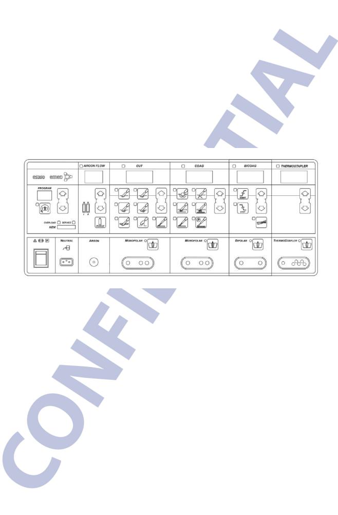
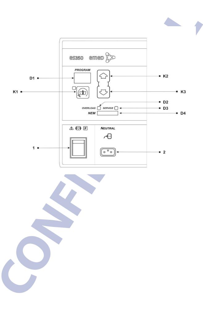
The front panel of the casing contains the following segments:
•power switch (1)
•neutral electrode socket (2)
•selected program display (D1)
•overload indicator (D2)
•information about the expiry deadline of technical inspection (D3)
•bar display – neutral electrode monitoring NEM (D4)
•MultiSwitch – for remote changes of settings (K1)
•program number selection (up K2, down K3)
ENG ver 2.0 |
2016-03 |
9 / 112 |

ELECTROSURGICAL UNIT Type series ES350 - SERVICE MANUAL
APPLIES ONLY TO Ref. Nos. 100-008 and 100-008-T
•argon electrode socket, argon outlet (3)
•gas flow volume display (D5)
•gas level indicator for cylinder I (D6)
•gas level indicator for cylinder II (D7)
•gas flow volume regulation buttons – increase (K4), decrease (K5)
•purge – filling up the instruments with argon (K6)
ENG ver 2.0 |
2016-03 |
10 / 112 |
ELECTROSURGICAL UNIT Type series ES350 - SERVICE MANUAL
•monopolar electrode I socket (4)
•display of selected cutting power (D8)
•pure cut (K7)
•cutting with various amount of hemostasis (K8, K9, K10)
•urological cutting (K11)
•endoscopic cutting (K12)
•argon-enhanced cutting (K13) - APPLIES ONLY TO Ref. Nos. 100-008 and 100-008-T
•power adjustment buttons cutting: increase (K14), decrease (K15)
•footswitch control – monopolar output I (K32)
ENG ver 2.0 |
2016-03 |
11 / 112 |
ELECTROSURGICAL UNIT Type series ES350 - SERVICE MANUAL
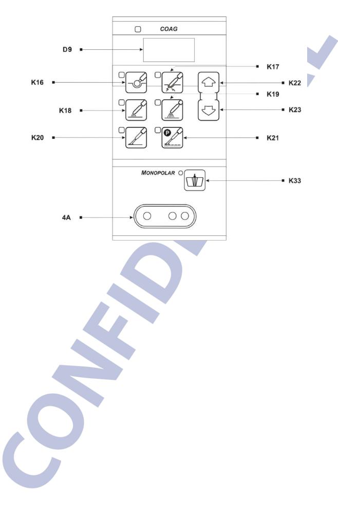
•monopolar electrode II socket (4A)
•display of selected monopolar coagulation power (D9)
•soft coagulation (K16)
•forced coagulation (K17)
•hybrid coagulation (K18)
•spray coagulation (K19)
•argon-enhanced coagulation (K20)
-APPLIES ONLY TO Ref. Nos. 100-008 and 100-008-T
•argon-enhanced pulse coagulation (K21)
-APPLIES ONLY TO Ref. Nos. 100-008 and 100-008-T
•power adjustment buttons coagulation: increase (K22), decrease (K23)
•footswitch control – monopolar output II (K33)
ENG ver 2.0 |
2016-03 |
12 / 112 |

ELECTROSURGICAL UNIT Type series ES350 - SERVICE MANUAL
•bipolar electrode socket (5)
•display of bipolar coagulation power (D10)
•automatic start-up of the bipolar coagulation AutoStart (K24)
•limitation of the bipolar coagulation time AutoStop (K25)
•power adjustment buttons bipolar coagulation: increase (K26), decrease (K27)
•bipolar cutting (K28)
•footswitch control – bipolar output (K34)
ENG ver 2.0 |
2016-03 |
13 / 112 |

ELECTROSURGICAL UNIT Type series ES350 - SERVICE MANUAL
APPLIES ONLY TO Ref. Nos. 100-008 and 100-008-T
•ThermoStapler® socket (6)
•display of selected ThermoStapler® power (D11)
•power adjustment buttons ThermoStapler®: increase (K30), decrease (K31)
•footswitch control – ThermoStapler® socket (K35)
ENG ver 2.0 |
2016-03 |
14 / 112 |

ELECTROSURGICAL UNIT Type series ES350 - SERVICE MANUAL
2.2Back panel
●monopolar/bipolar (universal) footswitch socket (7)
●bipolar footswitch socket (8)
●additional grounding pin (9)
●argon socket I (10) – APPLIES ONLY TO Ref. Nos. 100-008 and 100-008-T
●argon socket II (11) – APPLIES ONLY YO Ref. Nos. 100-008 and 100-008-T
●power cord socket (12)
●fuse sockets (13, 13A)
●manufacturer’s label (14)
●RS type service socket (15)
●USB type service socket (16)
ENG ver 2.0 |
2016-03 |
15 / 112 |

ELECTROSURGICAL UNIT Type series ES350 - SERVICE MANUAL
3MESSAGES FOR THE USER
|
Error POST |
|
|
Error code |
Description of the error |
|
|
311 |
Shorting of the CUT button on the handle at the OUT1 output. |
|
|
312 |
Shorting of the COAG button on the handle at the OUT1 output. |
|
|
321 |
Shorting of the CUT button on the handle at the OUT2 output. |
|
|
322 |
Shorting of the COAG button on the handle at the OUT2 output. |
|
|
331 |
Shorting of the CUT button on the handle at the OUT3 output. |
|
|
332 |
Shorting of the COAG button on the handle at the OUT3 output. |
|
|
341 |
Shorting of the CUT button on the handle at the OUT4 output. |
|
|
342 |
Shorting of the COAG button on the handle at the OUT4 output. |
|
|
371 |
Shorting of the CUT button on the UNIVERSAL footswitch. |
|
|
372 |
Shorting of the COAG button on the UNIVERSAL footswitch. |
|
|
381 |
Shorting of the CUT button on the BIPOLAR footswitch. |
|
|
382 |
Shorting of the COAG button on the BIPOLAR footswitch. |
|
|
373 |
Shorting of the MULTI button on the MONOPOLAR footswitch.. |
|
|
383 |
Shorting of the MULTI button on the BIPOLAR footswitch. |
|
|
314 |
Shorting of bipolar scissors (OUT1). |
|
|
324 |
Shorting of bipolar scissors (OUT2). |
|
|
334 |
Shorting of bipolar scissors (OUT3). |
|
|
344 |
Shorting of ThermoStapler clamps (OUT4). |
|
|
ENG ver 2.0 |
2016-03 |
16 / 112 |

ELECTROSURGICAL UNIT Type series ES350 - SERVICE MANUAL
Internal errors
Internal error – the electrosurgical unit does work properly. For safety reasons the functions of the unit cannot be activated. Please contact the authorised EMED service.
Error code |
Description of the error |
It is applies to the outputs responsible for the settings of relays. It is checked whether after a certain state has been generated at a processor port the
501desirable state has really been achieved at its legs.
It may be caused by a breakdown of the ULN2003 system which is connected to the processor outputs.
When the unit is started the voltage is read out at measurement pins in the state of no activation. All the measured results are treated as zero points and if voltage levels are higher than those acceptable in this state, an error is
502reported.
The acceptable voltage is the voltage corresponding to 7 units of a 8-bit converter with 5V reference voltage, i.e. 137mV as a maximum. It may be caused by failure to connect or incorrect connection of the MPM module.
The error of voltage, current or power output measurements.
The voltage, current or power output levels are continuously controlled during
503activation and at all times it is checked whether the obtained results make sense (e.g. it is an error when the voltage and current are almost zero, whereas the power is very high). If the measured results do not make sense and the situation repeats in successive measurements, an error is reported.
ENG ver 2.0 |
2016-03 |
17 / 112 |

ELECTROSURGICAL UNIT Type series ES350 - SERVICE MANUAL
4CONSTRUCTION
4.1Block diagram
ENG ver 2.0 |
2016-03 |
18 / 112 |

ELECTROSURGICAL UNIT Type series ES350 - SERVICE MANUAL
4.2Description of connections
1.2-wire cable (Connection GEN_VI - MOT_VI2)
2.multi-pin connectors located on the motherboard (Connection GEN_VI - MOT_VI2)
3.multi-pin connectors located on the motherboard (Connection SUP_VI - MOT_VI2)
4.multi-pin connectors located on the motherboard (Connection CPU2 - MOT_VI2)
5.4-wire cable for XBFS_RX_VI2 receiver (Connection XBFE_RX_VI2 - MOT_VI2)
6.power output cables (Connection OUT_S350 - MOT_VI2)
7.power output cables (Connection OUT_S350 - MOT_VI2)
8.power output cables (Connection OUT_S350 - MOT_VI2)
9.power output cables (Connection OUT_S350 - MOT_VI2)
10.neutral electrode power cable (Connection Front panel - MOT_VI2)
11.6-wire cable for footswitch socket UNIVERSAL (Connection Back panel – MOT_VI2)
12.6-wire cable for footswitch socket BIPOLAR (Connection Back panel - MOT_VI2)
13.multi-pin connectors located on the motherboard (Connection MPM - MOT_VI2)
14.multi pin connectors located on the motherboard (Connection MPM - MOT_VI2)
15.9-wire ribbon cable for Service output (Connection Back panel – CPU2)
16.2-wire power supply cable (Connection Back panel – Front panel)
17.2-wire power supply for main switch (Connection Front panel - MOT_VI2)
18.8-wire ribbon cable for gas sensors and valve control
ENG ver 2.0 |
2016-03 |
19 / 112 |

ELECTROSURGICAL UNIT Type series ES350 - SERVICE MANUAL
(Connection Back panel - ARG)
19.14-wire ribbon cable connecting the CPU module with argon module (Connection CPU2 – ARG)
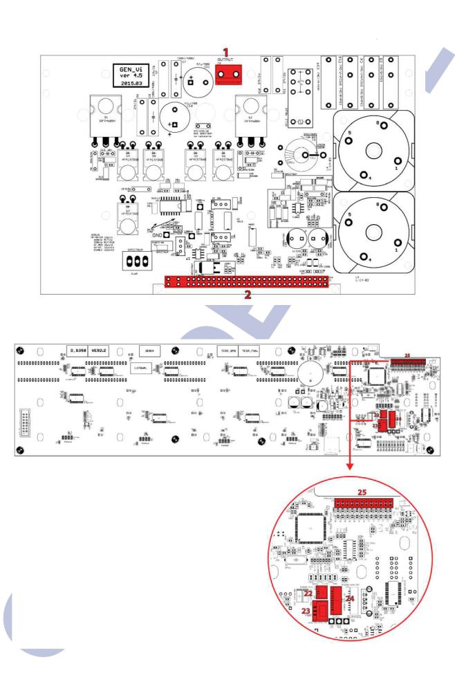
20.20-wire ribbon data transfer cable (Connection OUT_S350 – CPU2)
21.2-wire cable for audio signal (Connection Back panel – MOT_VI2)
22.2-wire cable for audio signal (Connection D_S350 – MOT_VI2)
23.3-wire cable for D_S350 power supply (Connection D_S350 – MOT_VI2)
24.9-wire data transfer cable (Connection D_S350 – CPU2)
25.12-wire cable (Connection D_S350 - keyboard)
26.cables for output socket on the front panel (Connection OUT_S350 – Front Panel)
27.cables for output socket on the front panel (Connection OUT_S350 – Front Panel)
28.cables for output socket on the front panel (Connection OUT_S350 – Front Panel)
29.cables for output socket on the front panel (Connection OUT_S350 – Front Panel)
30.2-wire cable for spray resistor
31.1 wire cable grounding upper casing
32.1 wire cable grounding module MOT_VI2
33.1 wire cabel grounding Front Panel
A1. Pneumatic cable (connecting the argon gas socket and argon valves K_ARG) located on the back panel
A2. Pneumatic cable (connecting the argon gas socket and argon valves K_ARG) located on the back panel
A3. Pneumatic cable (connecting the argon argon valves K_ARG and argon module ARG) located on the back panel
A4. Pneumatic cable (connecting the argon module ARG and argon gas socket, argon outlet) located on the front panel
ENG ver 2.0 |
2016-03 |
20 / 112 |

ELECTROSURGICAL UNIT Type series ES350 - SERVICE MANUAL
4.3Connection diagram
MOT_VI2 module
ENG ver 2.0 |
2016-03 |
21 / 112 |

ELECTROSURGICAL UNIT Type series ES350 - SERVICE MANUAL
CPU2 module
SUP_VI module
ENG ver 2.0 |
2016-03 |
22 / 112 |
ELECTROSURGICAL UNIT Type series ES350 - SERVICE MANUAL
GEN_VI module
D_S350 module
ENG ver 2.0 |
2016-03 |
23 / 112 |

ELECTROSURGICAL UNIT Type series ES350 - SERVICE MANUAL
ARG module
OUT_S350 module
ENG ver 2.0 |
2016-03 |
24 / 112 |

ELECTROSURGICAL UNIT Type series ES350 - SERVICE MANUAL
MPM module
XBFS_RX_VI2 module
ENG ver 2.0 |
2016-03 |
25 / 112 |

ELECTROSURGICAL UNIT Type series ES350 - SERVICE MANUAL
4.4Description of modules
4.4.1MOT_VI2 module – SP-1-02-06
1.Stand-By
2.The system which is responsible for switching on the main power supply with a switch on the front of the unit. In the Es350 unit, the jumper Jp3 is mounted; it deactivates the unit. The unit is switched on with a mechanical switch on the front.
3.Mains filter
4.The system of mains filters with the transformer T2 which supplies the logic of the PCB board.
5.Low-voltage power supplies
The system of low-voltage power supplies based on pulsed power converters for generating voltage levels of +12V and +5V. The correctness of generated voltage levels can be checked at the test points TP12 and TP13.
6.Operation of the radio switch
The system cooperates with the optional module XBFS mounted on the back wall of the unit under the black encasing.
ENG ver 2.0 |
2016-03 |
26 / 112 |

ELECTROSURGICAL UNIT Type series ES350 - SERVICE MANUAL
7.-5V power supply
It supplies the GEN, SUP and CPU modules connected to the connectors J10, J11 and J19.
8.Audio amplifier
The system is not mounted on the PCB.
9.NEM electrode
10.The system of filters which serves to detect how the neutral electrode adheres to the patient.
11.CPU
12.The connector which serves to connect the CPU module.
13.SUP
14.The connector which serves to connect the SUP_vi module.
15.GEN
16.The connector which serves to connect the GEN_Vi module.
17.MPM
18.The place for connecting the MPM measuring module.
19.Spray
20.The signal generator for Spray coagulation, the control and implementing parts.
21.Output systems
22.Output filters with a transformer separating the unit from the patient.
23.Relays
24.The relays which serve to distribute the energy of the unit to the appropriate outputs OUT1, OUT2 etc.
ENG ver 2.0 |
2016-03 |
27 / 112 |

ELECTROSURGICAL UNIT Type series ES350 - SERVICE MANUAL
4.4.2 CPU2 module – SP-1-03-04
ENG ver 2.0 |
2016-03 |
28 / 112 |

ELECTROSURGICAL UNIT Type series ES350 - SERVICE MANUAL
1.UREQ system.
It is a DAC which is controlled by a microcontroller. It sets the required voltage of the power supply.
2.Argon module connector.
3.A communication connector with the D_S350 module and the MAX232 voltage converter.
4.Service connector system.
Power supply and communication separated galvanically.
5.Relay control systems.
6.ENABLE signal buffer.
This buffer switches on the generator.
7.SPRAY_EN signal buffer.
It switches on the SPRAY generator.
8.Bipolar detection system.
9.Neutral electrode measurement system.
10.Indicator LED diodes.
11.XBFS microcontroller reset buffer.
12.Connector to the MOT_Vi2 module.
13.ISP connector for programming the microcontroller.
14.12VAC/75kHz generator.
It supplies modules which require galvanic insulation, e.g. OUT_S350.
15.The system which switches on signals for REM and BIPOLAR.
16.OUT_S350 module connector.
17.The system of the generator of 666kHz and HF-MOD signals. They serve to control the generator.
18.ADC filters.
19.Quartz
20.Watchdog.
21.Button filters.
22.Microcontroller.
23.Filters at the MOTVi2 connector.
ENG ver 2.0 |
2016-03 |
29 / 112 |
ELECTROSURGICAL UNIT Type series ES350 - SERVICE MANUAL
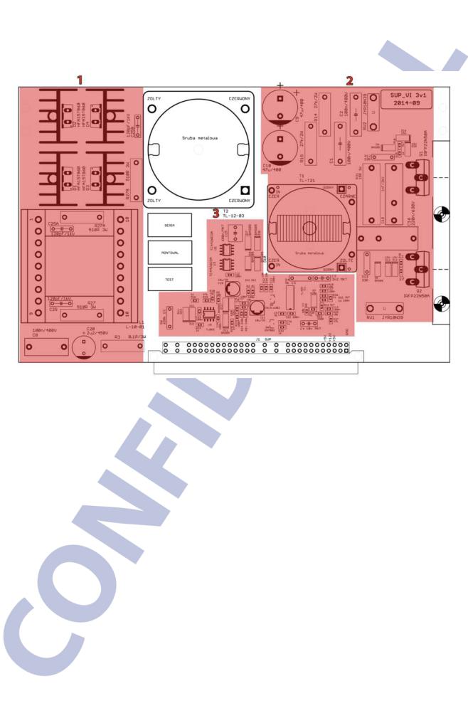
4.4.3SUP_VI module – SP-1-04-02
1.Output circuit
2.The power supply circuit separated with the transformer T2, with a rectifier and an output voltage filter.
3.Power circuit
The system transforms the rectified mains voltage into regulated HV voltage of the unit by keying the transistors Q1 and Q2. The transistors are controlled by the transformer T1.
4.Control system
5.A logic which serves to control power transistors so that the voltage output is consistent with the preset UREQ voltage.
ENG ver 2.0 |
2016-03 |
30 / 112 |
 Loading...