

Page 1

STM32F4 SOM (System-On-Module)
Baseboard
Hardware Architecture
Document No: STM-SOM-BSB-EXT-HA
Version: 1.1
Date: December 19, 2013
Page 2

Emcraft Systems
Table of Contents
1. INTRODUCTION ................................................................................................................................. 3
2. HARDWARE PLATFORM ................................................................................................................... 3
2.1. OVERVIEW ........................................................................................................................................ 3
2.2. FUNCTIONAL BLOCK DIAGRAM ............................................................................................................ 4
2.3. SOM CONNECTORS .......................................................................................................................... 4
2.4. USB UART INTERFACE ..................................................................................................................... 4
2.5. ETHERNET INTERFACE ....................................................................................................................... 4
2.6. USB OTG INTERFACE ....................................................................................................................... 4
2.7. ARM JTAG INTERFACE ..................................................................................................................... 5
2.8. POWER ............................................................................................................................................ 5
2.9. RESET BUTTON ................................................................................................................................. 5
2.10. RESET LED ...................................................................................................................................... 5
2.11. USER BUTTON AND USER LED ........................................................................................................... 5
2.12. BREADBOARD AREA ........................................................................................................................... 5
3. CONNECTORS ................................................................................................................................... 5
3.1. SOM-BSB-EXT CONNECTORS .......................................................................................................... 5
3.2. MINI USB TYPE B CONNECTORS ........................................................................................................ 6
3.3. RJ45 ETHERNET CONNECTOR ............................................................................................................ 6
3.4. SOM INTERFACE CONNECTORS.......................................................................................................... 6
3.5. ARM JTAG CONNECTOR .................................................................................................................. 6
3.6. BREADBOARD AREA ........................................................................................................................... 7
4. JUMPERS ......................................................................................................................................... 16
5. LEDS ................................................................................................................................................. 17
6. SWITCHES ....................................................................................................................................... 17
7. DOCUMENT REVISION HISTORY ................................................................................................... 17
STM32F4 SOM (System-On-Module) Baseboard 2/17 Version 1.1
Hardware Architecture December 19, 2013
Page 3

Emcraft Systems
1. Introduction
This document is the Technical Specification for the Emcraft Systems SOM (System-OnModule) baseboard (SOM-BSB-EXT).
The SOM-BSB-EXT is intended to provide a hardware platform for the evaluation and initial
custom product development with the Emcraft Systems STM32F4 SOM.
The SOM-BSB-EXT can be powered either from the USB port or from a separate external +5V
power supply.
All the unused pins of the STM32F4 SOM are routed to a breadboard area of the SOM-BSBEXT, which facilitates hardware and software prototyping.
The SOM-BSB-EXT comes complete with the hardware schematics and Bill of Materials (BOM)
file, facilitating the design of custom baseboard hardware for the STM32F4 SOM.
2. Hardware Platform
This section defines the hardware platform of the SOM-BSB-EXT.
2.1. Overview
The SOM-BSB-EXT implements the following hardware facilities:
• Two 80-pin SOM connectors;
• USB UART and power interfaces on a mini-USB connector;
• 10/100 Mbps Ethernet interface on an RJ-45 connector;
• USB OTG Interface and a mini-USB connector;
• Standard 20-pin ARM JTAG interface for debugging of the STM32F4 Cortex-M4 MCU;
• LDO regulator for conversion of the USB +5V to the +3.3V SOM power supply;
• Reset push button;
• Reset-out LED;
• User push button connected to the GPIO of the STM32F4 SOM;
• Power Good LED indicating presence of the STM32F4 SOM +3.3V power;
• User-controlled LED connected to the GPIO of the STM32F4 SOM;
• Unused STM32F4 SOM signals available on the breadboard area;
• Possibility of providing necessary power supply voltages (+5V, +3.3V) from external
sources through dedicated pads of the breadboard area.
STM32F4 SOM (System-On-Module) Baseboard 3/17 Version 1.1
Hardware Architecture December 19, 2013
Page 4
Emcraft Systems
SOM Connectors (P4, P6)
JTAG I/F
(
P3
, P5, JP2)
JP1
Reset
Button
(S1)
SOM
Reset Out
LED (DS1)
User
Button
(S2)
Power Good
LED (DS2)
ULPI USB PHY
Ethernet I/F
(P2)
USB OTG I
/F
(P
19
)
JP
3
LDO Regulator
+3.3V
+5
V USB
Breadboard Area
(P7-P14)
+5V External
Digital interfaces
GPIO signals
User LED
(DS4)
SOM Reset
+
5V
+3.3V
USB-UART
Bridge
USB Device I/F
(P
1)
Current
Switch
VBUS
+3,3 V External
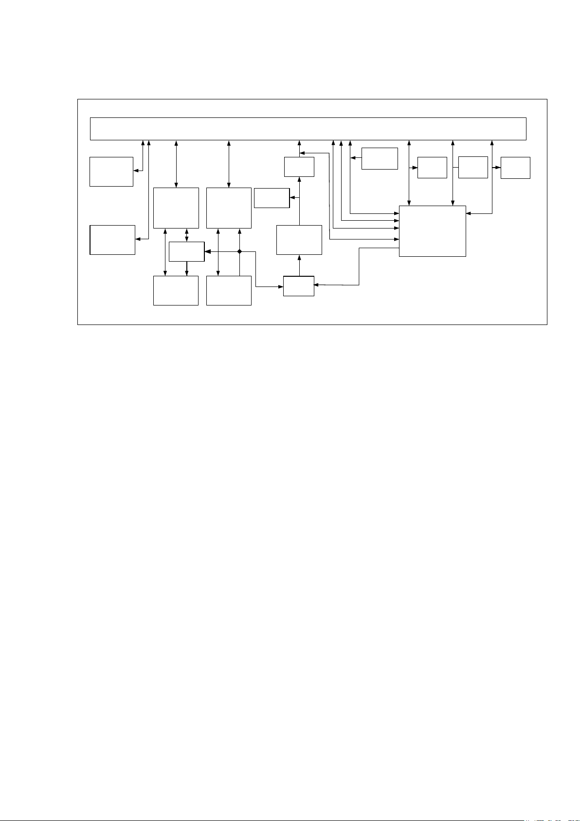
2.2. Functional Block Diagram
Figure 1 is the functional block diagram of the SOM-BSB-EXT.
Figure 1: SOM-BSB-EXT Functional Block Diagram
2.3. SOM Connectors
The SOM-BSB-EXT provides two Hirose DF40 series connectors for the connection to the
STM32F4 SOM. The connectors are 80-pin, 0.4 mm pitch receptacles, providing 4 mm
stacking height.
2.4. USB UART Interface
The SOM-BSB-EXT provides a USB UART interface on the type B mini USB connector (P1).
The interface is provided using an FTDI FT232RL USB-UART bridge. The FT232RL UART TX
and RX pins are connected to the STM32F4 SOM serial console UART port.
2.5. Ethernet Interface
The SOM-BSB-EXT provides the 10/100 Mbps Ethernet interface using the P2 connector. This
is an RJ-45 Ethernet port providing 10 Mbps (10BASE-T) and 100 Mbps (100BASE-TX)
protocols.
The SOM-BSB-EXT provides two status LEDs integrated in the P2 connector. The LEDs are:
• Yellow, is used to indicate the 10/100 Mbps link status, when lit;
• Green, is used to indicate RX/TX activity, when blinking.
The LEDs are connected on the SOM-BSB-EXT between the STM32F4 SOM outputs and +3.3
V power supply.
2.6. USB OTG Interface
The SOM-BSB-EXT provides the USB OTG interface on the mini B USB connector (P19).
The interface is implemented using the USB ULPI interface of the STM32F4 MCU. On the
SOM-BSB-EXT the interface is converted to the USB OTG interface, using SMSC USB3300EZK ULPI USB PHY device.
STM32F4 SOM (System-On-Module) Baseboard 4/17 Version 1.1
Hardware Architecture December 19, 2013
Page 5

Emcraft Systems
For custom designs using the SOM-BSB-EXT schematics as a reference it is recommended to
include voltage suppressors such as Littelfuse’s PGB1010603M, onto the USB data lines
(USB_OTG_N, USB_OTG_P, USB_N, and USB_P) to improve a quality of the USB signals.
2.7. ARM JTAG Interface
The SOM-BSB-EXT provides the ARM JTAG interface on the P3 connector for debugging of
the STM32F4 MCU on the STM32F4 SOM.
The connector is a standard 20-pin JTAG port supported by standard Cortex-M4
programmers/emulators.
2.8. Power
The SOM-BSB-EXT receives the +5 V power from the P1 mini-USB connector. Additionally, it
is possible to supply an external +5 V power through the dedicated pad P10.2 of the SOMBSB-EXT breadboard area. Configuration of the +5 V input power supply is defined by the
JP3 header. The default settings of the JP3 are: 1-3 open, 2-4 closed. For further details on
the JP3 settings, see Section 4.
The +3.3 V supply voltage for the STM32F4 SOM and other components of the SOM-BSBEXT is derived from the +5 V input voltage using the TPS73733DCQ LDO regulator. The
regulator dissipates approximately 1 Watt and is mounted on a heatsink. The SOM-BSB-EXT
provides a green Power Good LED that indicates presence of the +3.3 V power on the output
of the LDO regulator.
It is possible to turn the LDO regulator off for debug purposes. To do so, the control signal
VCC3_EN (P10.6 pad of the SOM-BSB-EXT breadboard area) must be connected to the
ground.
2.9. Reset Button
The SOM-BSB-EXT provides the S1 reset button used to trigger a hardware reset of the SOM.
2.10. Reset LED
The Reset LED indicates the status of the nRESET_OUT signal of the SOM. The LED is lit when
nRESET_OUT is low.
2.11. User Button and User LED
The SOM-BSB-EXT provides the S2 user button and the DS4 user LED as a simple
input/output interface for testing and demonstration purposes.
For further details, refer to Sections 5 and 6.
2.12. Breadboard Area
All unused signal pins of the SOM are available on the breadboard area marked as P7-P14.
For further details, refer to Section 3.6.
3. Connectors
This section provides a full pin definition of all connectors available on the SOM-BSB-EXT.
3.1. SOM-BSB-EXT Connectors
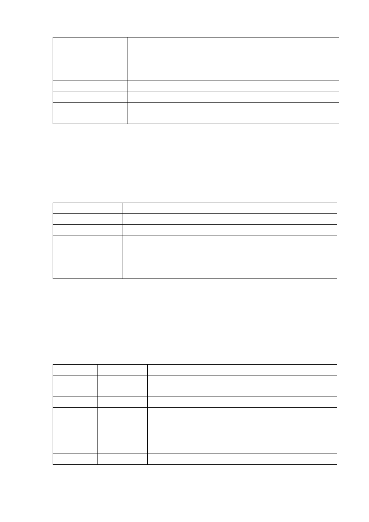
Table 1 provides a summary of the SOM-BSB-EXT connectors:
STM32F4 SOM (System-On-Module) Baseboard 5/17 Version 1.1
Hardware Architecture December 19, 2013
Page 6
Emcraft Systems
Connector
Description
P1
Mini USB Type B connector (USB UART interface)
P2
RJ-45 Ethernet connector
P3
ARM JTAG connector
P4, P6
SOM interface connectors
P5
Microsemi FlashPro JTAG connector
P7-P14
Breadboard area (no actual connectors installed)
P19
Mini USB Type B connector (USB OTG interface)
Pin
Signal
1
TX+
2
TX-
3
RX+
4, 5
Unused pair; terminated on the SOM-BSB-EXT
6
RX-
7, 8
Unused pair, terminated on the SOM-BSB-EXT
Pin
Signal
Type
Description
1
VCC3
Power
Reference voltage of the STM32F4 MCU.
2 - -
Not connected on SOM-BSB-EXT
3
JTAG_nTRST
Input
STM32F4 MCU JTAG controller reset.
4, 6, 8, 10,
GND
Power
Ground of the STM32F4 MCU.
5
JTAG_TDI
Input
JTAG data input to the STM32F4 MCU.
7
JTAG_TMS
Input
JTAG mode select.
9
JTAG_TCK
Input
JTAG clock signal to the STM32F4 MCU.
Table 1: SOM-BSB-EXT Connectors
3.2. Mini USB Type B Connectors
The P1 and P19 USB connectors have a standard USB mini-B receptacle pin-out.
3.3. RJ45 Ethernet Connector
The P2 is a standard RJ-45 NIC connector with the following definition:
Table 2: Ethernet Connector
3.4. SOM Interface Connectors
For the definition of the two 80-pin SOM connectors (P4 and P6) refer to the STM32F4 SOM
Hardware Architecture document.
3.5. ARM JTAG Connector
The P3 is a standard 20-pin ARM JTAG connector with the following definition:
12, 14, 16,
18, 20
STM32F4 SOM (System-On-Module) Baseboard 6/17 Version 1.1
Hardware Architecture December 19, 2013
Page 7

Emcraft Systems
Pin
Signal
Type
Description
11, 17, 19
-
-
These pins are not connected to the SOM
13
JTAG_TDO
Output
JTAG data output from the STM32F4 MCU.
15
nRESET_IN
Input/Output
Reset signal of the STM32F4 MCU.
Breadboar
Signal
SOM
Connected To
1
VCC3
77, 79 on P4
STM32F4 SOM +3.3 V power supply.
2, 8, 10, 12,
GND
2, 3, 5, 8, 9, 11, 14, 57,
STM32F4 SOM ground.
3
ADC8
68 on P4
STM32F4 pin C13
4
ADC17
66 on P4
Not connected on STM32F4 SOM.
5
ADC9
64 on P4
STM32F4 pin D1
6
ADC18
40 on P4
STM32F4 pin N4
7
ADC10
52 on P4
Not connected on STM32F4 SOM.
9
ADC11
48 on P4
Not connected on STM32F4 SOM.
11
ADC12
55 on P4
STM32F4 pin L2
13
ADC13
58 on P4
Not connected on STM32F4 SOM.
15
ADC14
53 on P4
Not connected on STM32F4 SOM.
17
ADC15
50 on P4
STM32F4 pin A9
19
ADC16
42 on P4
Not connected on STM32F4 SOM.
connectors and are pulled to GND on SOM-
BSB-EXT.
Table 3: ARM JTAG Connector
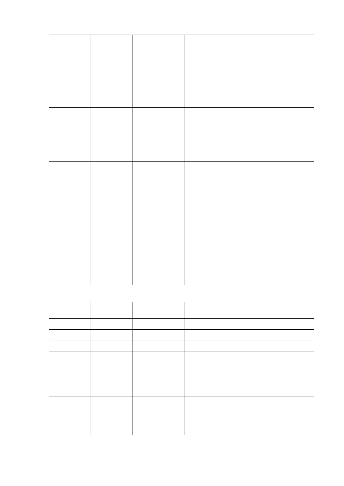
3.6. Breadboard Area
The test points in the breadboard area are grouped as PCB patterns for 12x2 2 mm pitch
through-hole connectors (P7-P14) with the following definition:
d
Pin #
14, 16, 18,
20, 21, 22,
23, 24,
Name
Connector
Pin
75, 76 on P4;
1, 6, 7, 12, 20, 23, 24,
28, 29, 39, 52, 55 on
P6
(PI3/TIM8_ETR/SPI2_MOSI/I2S2_SD/
DCMI_D10/FMC_D27).
(EVENTOUT/RTC_AF2).
(PA4/SPI1_NSS/SPI3_NSS/USART2_CK/
DCMI_HSYNC/OTG_HS_SOF/I2S3_WS/LCD_VSYNC/
ADC12_IN4/DAC1_OUT).
STM32F4 SOM (System-On-Module) Baseboard 7/17 Version 1.1
Hardware Architecture December 19, 2013
(PF9/TIM14_CH1/FMC_CD/
SPI5_MOSI/SAI1_FS_B/ADC3_IN7).
(PB4/NJTRST/TIM3_CH1/SPI1_MISO/
SPI3_MISO/2S3ext_SD/EVENTOUT)
through resistor R35 (not installed by default).
Table 4: P7 Breadboard Area Connector
Page 8
Emcraft Systems
Breadboard
Signal
SOM Connector
Connected To
1
VCC3
77, 79 on P4
STM32F4 SOM +3.3V power supply.
2, 4, 6, 8,
GND
2, 3, 5, 8, 9, 11,
STM32F4 SOM ground.
3
ADC0
70 on P4
STM32F4 pin P3
5
ADC1
60 on P4
STM32F4 pin N3
7
ADC4
56 on P4
STM32F4 pin D2
9
ADC5
54 on P4
Not connected on STM32F4 SOM.
11
ADC3
46 on P4
Not connected on STM32F4 SOM.
13
ADC2
44 on P4
STM32F4 pin D11
15
ADC6
51 on P4
STM32F4 pin L3
17
ADC7
47 on P4
STM32F4 pin A13
Breadboard
Signal
SOM Connector
Connected To
1
VCC3
77, 79 on P4
+3.3 V SOM power supply.
2
VCC1V5
78, 80 on P4
Not connected on STM32F4 SOM.
3
VBATT
74 on P4
STM32F4 pin C1 (VBAT).
4, 12, 21,
GND
2, 3, 5, 8, 9, 11,
STM32F4 SOM ground.
5
1V5_EN
72 on P4
Not connected on STM32F4 SOM.
6
UART_1_TXD
28 on P4
STM32F4 pin K1
Pin #
10,12, 14,
16, 18, 19,
20, 21, 22,
23, 24
Name
Pin
14, 57, 75, 76
on P4;
1, 6, 7, 12, 20,
23, 24, 28, 29,
39, 52, 55 on P6
(PA6/SPI1_MISO/TIM8_BKIN/TIM13_CH1/
DCMI_PIXCLK/TIM3_CH1/TIM1_BKIN/
LCD_G2/ADC12_IN6).
(PA0-WKUP/ADC123_IN0/WKUP).
(EVENTOUT/RTC_AF2).
Pin #
22, 23, 24
(PD3/SPI2_SCK/I2S2_CK/USART2_CTS/
FMC_CLK/LCD_G7).
(PF8/TIM13_CH1/FMC_NIOWR/SPI5_MISO/
SAI1_SCK_B/ADC3_IN6).
(PA15/JTDI/TIM2_CH1/TIM2_ETR/SPI1_NSS/
SPI3_NSS/I2S3_WS/EVENTOUT).
Table 5: P8 Breadboard Area Connector
Name
Pin
14, 57, 75, 76
on P4;
1, 6, 7, 12, 20,
23, 24, 28, 29,
39, 52, 55 on P6
STM32F4 SOM (System-On-Module) Baseboard 8/17 Version 1.1
Hardware Architecture December 19, 2013
(PF7/TIM11_CH1/FMC_NREG/SPI5_SCK/
UART7_Tx/SAI1_MCLK_B/ADC3_IN5).
Page 9

Emcraft Systems
Breadboard
Signal
SOM Connector
Connected To
7
UART_1_RXD
31 on P4
STM32F4 pin K2
8
I2C_0_SCL
33 on P4
STM32F4 pin A5
9
I2C_0_SDA
27 on P4
STM32F4 pin B5
10
I2C_1_SDA
26 on P4
Not connected on STM32F4 SOM.
11
I2C_1_SCL
25 on P4
Not connected on STM32F4 SOM.
13
SPI0_DO
63 on P4
STM32F4 pin R15
14
SPI0_DI
65 on P4
STM32F4 pin R14
15
SPI0_nSS
73 on P4
STM32F4 pin B4
16
SPI0_CLK
71 on P4
STM32F4 pin D14
17
SPI1_nSS
69 on P4
Not connected on STM32F4 SOM.
18
SPI1_CLK
67 on P4
STM32F4 pin M11
19
SPI1_DI
61 on P4
Not connected on STM32F4 SOM.
20
SPI1_DO
59 on P4
Not connected on STM32F4 SOM.
Breadboard
Signal
SOM Connector
Connected To
1
VCC3
77, 79 on P4
STM32F4 SOM +3.3V power supply.
2
+5V_IN
N/A
SOM-BSB-EXT JP3 pin 1, external +5V power
Pin #
Name
Pin
(PF6/TIM10_CH1/FMC_NIORD/SPI5_NSS/
UART7_Rx/SAI1_SD_B/ADC3_IN4).
(PB8/TIM4_CH3/SDIO_D4/TIM10_CH1/
DCMI_D6/ETH_MII_TXD3/I2C1_SCL/
CAN1_RX/LCD_B6).
(PB7/TIM4_CH2/I2C1_SDA/
USART1_RX/FMC_NL).
(PB15/SPI2_MOSI/I2S2_SD/TIM1_CH3N/
TIM8_CH3N/TIM12_CH2/
RTC_50HZ/OTG_HS_DP) through resistor R19.
(PB14/SPI2_MISO/TIM1_CH2N/TIM12_CH1/
USART3_RTS/TIM8_CH2N/I2S2ext_SD/
OTG_HS_DM).
Pin #
(PB9/SPI2_NSS/I2S2_WS/TIM4_CH4/
TIM11_CH1/SDIO_D5/DCMI_D7/
I2C1_SDA/CAN1_TX/LCD_B7) through resistor
R21.
(PI1/SPI2_SCK/I2S2_CK/DCMI_D8/
FMC_D25/LCD_G6) through resistor R20.
(PH6/I2C2_SMBA/TIM12_CH1/ETH_MII_RXD2/
SPI5_SCK/DCMI_D8/FMC_SDNE1).
Table 6: P9 Breadboard Area Connector
Name
Pin
STM32F4 SOM (System-On-Module) Baseboard 9/17 Version 1.1
Hardware Architecture December 19, 2013
supply.
Page 10

Emcraft Systems
Breadboard
Signal
SOM Connector
Connected To
3, 21, 22,
GND
2, 3, 5, 8, 9, 11,
STM32F4 SOM ground.
4
nRESET_OUT
15 on P4
STM32F4 pin J1 (NRST);
5
nRESET_IN
13 on P4
STM32F4 pin J1 (NRST);
6
VCC3_EN
N/A
SOM-BSB-EXT U2 pin 5 (+3.3 V LDO enable).
7
GPIO_90
37 on P4
Not connected on STM32F4 SOM.
8
GPIO_88
23 on P4
STM32F4 pin M6 (PB2-BOOT1/EVENTOUT);
9
GPIO_89
35 on P4
Not connected on STM32F4 SOM.
10
GPIO_87
21 on P4
STM32F4 pin F15
11
GPIO_86
19 on P4
STM32F4 pin A11 (PD7/USART2_CK/FMC_NE1).
12
GPIO_85
17 on P4
Not connected on STM32F4 SOM.
13
GPIO_91
39 on P4
Not connected on STM32F4 SOM.
14
GPIO_83
32 on P4
Not connected on STM32F4 SOM.
15
GPIO_92
41 on P4
Not connected on STM32F4 SOM.
16
GPIO_84
34 on P4
Not connected on STM32F4 SOM.
17
GPIO_93
43 on P4
Not connected on STM32F4 SOM.
18
GPIO_82
18 on P4
Not connected on STM32F4 SOM.
19
GPIO_94
45 on P4
Not connected on STM32F4 SOM.
20
GPIO_81
16 on P4
STM32F4 pin H15
Breadboard
Signal
SOM Connector
Connected To
1
VCC3
77, 79 on P4
STM32F4 SOM +3.3V power supply.
2, 23, 24
GND
2, 3, 5, 8, 9, 11,
STM32F4 SOM ground.
Pin #
23, 24
Name
Pin
14, 57, 75, 76
on P4;
1, 6, 7, 12, 20,
23, 24, 28, 29,
39, 52, 55 on P6
SOM-BSB-EXT DS1 LED.
SOM-BSB-EXT S1 reset button.
SOM-BSB-EXT DS4 LED.
(PA8/MCO1/USART1_CK/TIM1_CH1/
I2C3_SCL/ OTG_FS_SOF/LCD_R6).
Table 7: P10 Breadboard Area Connector
Pin #
STM32F4 SOM (System-On-Module) Baseboard 10/17 Version 1.1
Hardware Architecture December 19, 2013
Name
(PC6/I2S2_MCK/TIM8_CH1/SDIO_D6/
USART6_TX/DCMI_D0/TIM3_CH1/LCD_HSYNC).
Pin
14, 57, 75, 76
on P4;
1, 6, 7, 12, 20,
23, 24, 28, 29,
39, 52, 55 on P6
Page 11

Emcraft Systems
Breadboard
Signal
SOM Connector
Connected To
3
GPIO_20
20 on P6
STM32F4 SOM ground.
4
GPIO_26
Not connected to STM32F4 SOM.
5
GPIO_18
18 on P6
Not connected on STM32F4 SOM (default
STM32F4 pin R3
6
GPIO_24
24 on P6
STM32F4 SOM ground.
7
GPIO_16
16 on P6
Not connected to STM32F4 SOM.
8
GPIO_22
22 on P6
Not connected on STM32F4 SOM (default
STM32F4 pin N2
9
GPIO_14
14 on P6
Not connected on STM32F4 SOM (default
STM32F4 pin B9
10
GPIO_28
28 on P6
STM32F4 SOM ground.
11
GPIO_6
6 on P6
STM32F4 SOM ground.
12
GPIO_30
Not connected to STM32F4 SOM.
13
GPIO_10
10 on P6
Not connected on STM32F4 SOM(default
STM32F4 pin N5
14
GPIO_32
Not connected to STM32F4 SOM.
15
GPIO_8
8 on P6
Not connected on STM32F4 SOM (default
STM32F4 pin P5
16
GPIO_34
Not connected to STM32F4 SOM.
17
GPIO_12
12 on P6
STM32F4 SOM ground.
18
GPIO_36
Not connected to STM32F4 SOM.
Pin #
Name
Pin
option).
(PA7/SPI1_MOSI/TIM8_CH1N/TIM14_CH1/
TIM3_CH2/ETH_MII_RX_DV/TIM1_CH1N/
ETH_RMII_CRS_DV/ADC12_IN7) through
resistors R31 and R12 (build-time option).
option).
(PA1/USART2_RTS/UART4_RX/
ETH_RMII_REF_CLK/ETH_MII_RX_CLK/
TIM5_CH2/TIM2_CH2/ADC123_IN1) through
resistor R32 (build-time option).
option).
(PG11/FMC_NCE4_2/ETH_MII_TX_EN/
ETH_RMII_TX_EN/DCMI_D3/LCD_B3) through
resistors R28 and R7 (build-time option).
option).
(PC4/ETH_RMII_RX_D0/ETH_MII_RX_D0/
ADC12_IN14) through resistors R30 and R11
(build-time option).
option).
(PC5/ETH_RMII_RX_D1/ETH_MII_RX_D1/
ADC12_IN15) through resistors R29 and R10
(build-time option).
STM32F4 SOM (System-On-Module) Baseboard 11/17 Version 1.1
Hardware Architecture December 19, 2013
Page 12

Emcraft Systems
Breadboard
Signal
SOM Connector
Connected To
19
GPIO_4
4 on P6
Not connected on STM32F4 SOM (default
STM32F4 pin A8
20
GPIO_38
Not connected to STM32F4 SOM.
21
GPIO_2
2 on P6
Not connected on STM32F4 SOM (default
STM32F4 pin A7
22
GPIO_40
Not connected to STM32F4 SOM.
Breadboard
Signal
SOM Connector
Connected To
1
VCC3
77, 79 on P4
STM32F4 SOM +3.3V power supply.
2, 23, 24
GND
2, 3, 5, 8, 9, 11,
STM32F4 SOM ground.
3
GPIO_56
56 on P6
Not connected on STM32F4 SOM.
4
GPIO_62
62 on P6
STM32F4 pin B13
5
GPIO_58
58 on P6
Not connected on STM32F4 SOM.
6
GPIO_64
64 on P6
STM32F4 pin B14
7
GPIO_60
60 on P6
Not connected on STM32F4 SOM.
8
GPIO_66
66 on P6
STM32F4 pin F14
9
GPIO_54
54 on P6
Not connected on STM32F4 SOM.
10
GPIO_68
68 on P6
STM32F4 pin G14
11
GPIO_52
52 on P6
STM32F4 SOM ground.
12
GPIO_70
70 on P6
Not connected on STM32F4 SOM.
Pin #
Pin #
Name
Pin
option).
(PG13/FMC_A24/USART6_CTS/ETH_MII_TXD0/
ETH_RMII_TXD0/SPI6_SCK) through resistors
R27 and R9 (build-time option).
option).
(PG14/FMC_A25/USART6_TX/ETH_MII_TXD1/
ETH_RMII_TXD1/SPI6_MOSI) through resistors
R26 and R8 (build-time option).
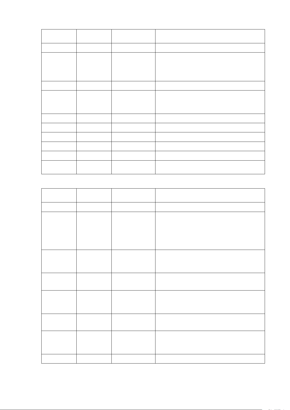
Table 8: P11 Breadboard Area Connector
Name
Pin
14, 57, 75, 76
on P4;
1, 6, 7, 12, 20,
23, 24, 28, 29,
39, 52, 55 on P6
(PC11/I2S3ext_SD/SPI3_MISO/UART4_RX/
USART3_RX/SDIO_D3).
(PC10/SPI3_SCK/I2S3_CK/UART4_TX/
USART3_TX/SDIO_D2/LCD_R2).
(PC9/I2S_CKIN/MCO2/TIM8_CH4/SDIO_D1/
I2C3_SDA/DCMI_D3).
STM32F4 SOM (System-On-Module) Baseboard 12/17 Version 1.1
Hardware Architecture December 19, 2013
(PC8/TIM8_CH3/SDIO_D0/TIM3_CH3/
USART6_CK/DCMI_D2).
Page 13
Emcraft Systems
Breadboard
Signal
SOM Connector
Connected To
13
GPIO_50
Not connected to STM32F4 SOM.
14
GPIO_72
72 on P6
STM32F4 pin A12
15
GPIO_44
Not connected to STM32F4 SOM.
16
GPIO_74
74 on P6
STM32F4 pin D12
17
GPIO_46
Not connected to STM32F4 SOM.
18
GPIO_76
76 on P6
Not connected on STM32F4 SOM.
19
GPIO_48
Not connected to STM32F4 SOM.
20
GPIO_78
78 on P6
Not connected on STM32F4 SOM.
21
GPIO_42
Not connected to STM32F4 SOM.
22
GPIO_80
80 on P6
Not connected on STM32F4 SOM.
Breadboard
Signal
SOM Connector
Connected To
1
VCC3
77, 79 on P4
STM32F4 SOM +3.3V power supply.
2, 23, 24
GND
2, 3, 5, 8, 9, 11,
STM32F4 SOM ground.
3
GPIO_61
61 on P6
STM32F4 pin D13
4
GPIO_59
59 on P6
STM32F4 pin E13
5
GPIO_63
63 on P6
STM32F4 pin E14
6
GPIO_57
57 on P6
STM32F4 pin E12
7
GPIO_65
65 on P6
STM32F4 pin G15
8
GPIO_55
55 on P6
STM32F4 SOM ground.
Pin #
Name
Pin
(PC12/UART5_TX/SDIO_CK/DCMI_D9/
SPI3_MOSI/I2S3_SD/USART3_CK) through
resistor R22.
(PD2/TIM3_ETR/UART5_RX/
SDIO_CMD/DCMI_D11).
SOM-BSB-EXT DS3 LED.
Pin #
Table 9: P12 Breadboard Area Connector
Name
Pin
14, 57, 75, 76
on P4;
1, 6, 7, 12, 20,
23, 24, 28, 29,
39, 52, 55 on P6
(PH15/TIM8_CH3N/DCMI_D11/
FMC_D23/LCD_G4).
(PH14/TIM8_CH2N/DCMI_D4/FMC_D22/LCD_G3).
(PI0/TIM5_CH4/SPI2_NSS/I2S2_WS/
DCMI_D13/FMC_D24/LCD_G5).
STM32F4 SOM (System-On-Module) Baseboard 13/17 Version 1.1
Hardware Architecture December 19, 2013
(PH13/TIM8_CH1N/CAN1_TX/FMC_D21/LCD_G2).
(PC7/I2S3_MCK/TIM8_CH2/SDIO_D7/
USART6_RX/DCMI_D1/TIM3_CH2/LCD_G6).
Page 14

Emcraft Systems
Breadboard
Signal
SOM Connector
Connected To
9
GPIO_67
67 on P6
STM32F4 pin C14
10
GPIO_53
53 on P6
STM32F4 pin J15
11
GPIO_69
69 on P6
STM32F4 pin F4
12
GPIO_51
51 on P6
STM32F4 pin K12
13
GPIO_71
71 on P6
Not connected on STM32F4 SOM.
14
GPIO_49
49 on P6
STM32F4 pin L12
15
GPIO_73
73 on P6
Not connected on STM32F4 SOM.
16
GPIO_45
45 on P6
STM32F4 pin M13
17
GPIO_79
79 on P6
STM32F4 pin A2
18
GPIO_47
47 on P6
STM32F4 pin L13
19
GPIO_77
77 on P6
Not connected on STM32F4 SOM.
20
GPIO_43
43 on P6
STM32F4 pin M12
21
GPIO_75
75 on P6
Not connected on STM32F4 SOM.
22
GPIO_41
41 on P6
STM32F4 pin G4
Breadboard
Signal
SOM Connector
Connected To
1
VCC3
77, 79 on P4
+3.3 V SOM power supply.
2, 23, 24
GND
2, 3, 5, 8, 9, 11,
STM32F4 SOM ground.
Pin #
Name
Pin
(PI2/TIM8_CH4/SPI2_MISO/DCMI_D9/
I2S2ext_SD/FMC_D26/LCD_G7).
(PG6/FMC_INT2/DCMI_D12/LCD_R7).
(PH2/ETH_MII_CRS/FMC_SDCKE0/LCD_R0).
(PH12/TIM5_CH3/DCMI_D3/FMC_D20/LCD_R6).
(PH11/TIM5_CH2/DCMI_D2/FMC_D19/LCD_R5).
(PH9/I2C3_SMBA/TIM12_CH2/DCMI_D0/
FMC_D17/LCD_R3).
Pin #
(PE2/SPI4_SCK/SAI1_MCLK_A/
ETH_MII_TXD3/FMC_A23);
SOM-BSB-EXT S2 user button.
(PH10/TIM5_CH1/DCMI_D1/FMC_D18/LCD_R4).
(PH8/I2C3_SDA/DCMI_HSYNC/FMC_D16/LCD_R2).
(PH3/ETH_MII_COL/FMC_SDNE0/LCD_R1).
Table 10: P13 Breadboard Area Connector
Name
Pin
14, 57, 75, 76
on P4;
1, 6, 7, 12, 20,
23, 24, 28, 29,
39, 52, 55 on P6
STM32F4 SOM (System-On-Module) Baseboard 14/17 Version 1.1
Hardware Architecture December 19, 2013
Page 15

Emcraft Systems
Breadboard
Signal
SOM Connector
Connected To
3
GPIO_25
25 on P6
STM32F4 pin B8
4
GPIO_19
19 on P6
STM32F4 pin E3
5
GPIO_23
23 on P6
STM32F4 SOM ground.
6
GPIO_17
17 on P6
STM32F4 pin L1
7
GPIO_21
21 on P6
STM32F4 pin D3
8
GPIO_15
15 on P6
STM32F4 pin J14
9
GPIO_27
27 on P6
STM32F4 pin B10
10
GPIO_13
13 on P6
STM32F4 pin N12
11
GPIO_29
29 on P6
STM32F4 SOM ground.
12
GPIO_11
11 on P6
STM32F4 pin B11
13
GPIO_31
31 on P6
STM32F4 pin D4
14
GPIO_9
9 on P6
STM32F4 pin E15
15
GPIO_33
33 on P6
STM32F4 pin C4
16
GPIO_7
7 on P6
STM32F4 SOM ground.
17
GPIO_35
35 on P6
STM32F4 pin C3
18
GPIO_5
5 on P6
STM32F4 pin C15
19
GPIO_37
37 on P6
STM32F4 pin C2
Pin #
Name
Pin
(PG12/FMC_NE4/USART6_RTS/SPI6_MISO/
LCD_B1/LCD_B4).
(PI10/ETH_MII_RX_ER/FMC_D31/LCD_HSYNC).
(PF10/FMC_INTR/DCMI_D11/LCD_DE/ADC3_IN8).
(PI9/CAN1_RX/FMC_D30/LCD_VSYNC).
(PG7/FMC_INT3/USART6_CK/DCMI_D13/LCD_CLK)
through resistor R25.
(PG10/FMC_NCE4_1/FMC_NE3/
DCMI_D2/LCD_B2/LCD_G3).
(PH7/I2C3_SCL/ETH_MII_RXD3/
SPI5_MISO/DCMI_D9/FMC_SDCKE1).
(PD6/SPI3_MOSI/I2S3_SD/SAI1_SD_A/
USART2_RX/FMC_NWAIT/LCD_B2).
(PI4/TIM8_BKIN/DCMI_D5/FMC_NBL2/LCD_B4).
(PA9/USART1_TX/TIM1_CH2/I2C3_SMBA/
DCMI_D0/OTG_FS_VBUS).
(PI5/TIM8_CH1/DCMI_VSYNC/
FMC_NBL3/LCD_B5).
(PI6/TIM8_CH2/DCMI_D6/FMC_D28/LCD_B6).
STM32F4 SOM (System-On-Module) Baseboard 15/17 Version 1.1
Hardware Architecture December 19, 2013
(PA11/USART1_CTS/CAN1_RX/TIM1_CH4/
LCD_R4/OTG_FS_DM).
(PI7/TIM8_CH3/DCMI_D7/FMC_D29/LCD_B7).
Page 16

Emcraft Systems
Breadboard
Signal
SOM Connector
Connected To
20
GPIO_3
3 on P6
STM32F4 pin B15
21
GPIO_39
39 on P6
STM32F4 SOM ground.
22
GPIO_1
1 on P6
STM32F4 SOM ground.
Designation
Name
Settings
Description
JP1
VCC3
1-2 closed
The +3.3 V voltage from the output
1-2 open
The +3.3 V voltage from the output
3-4 closed
The +3.3V voltage from the output
3-4 open
The +3.3 V voltage from the output
JP2
JTAG Mode
1-2 open
The settings of JP2 do not affect the
3-4 open
JP3
VCC5
1-3 closed
The +3.3 V LDO regulator is
1-3 open
The +3.3 V LDO regulator is
Pin #
Name
Table 11: P14 Breadboard Area Connector
Pin
(PA12/USART1_RTS/CAN1_TX/TIM1_ETR/
LCD_R5/OTG_FS_DP).
4. Jumpers
The SOM-BSB-EXT provides the configurable jumpers listed in the table below. The default
settings are marked in bold:
of the U2 LDO regulator is applied to
the STM32F4 SOM and to the SOMBSB-EXT.
of the U2 LDO regulator is applied to
the STM32F4 SOM and to the SOMBSB-EXT through R35 160 mOhm
resistor. This setting enables
measuring power, voltage and
current of the +3.3 V rail using ARM
Energy Probe.
Selection
2-4 open
2-4 closed
of the U2 LDO regulator is applied to
the D1 double diode ORing scheme.
When present, this voltage is used to
provide the VBATT power supply for
the STM32F4 SOM RTC to spare the
lithium battery charge.
of the U2 LDO regulator is not
applied to the D1 double diode
ORing scheme.
STM32F4 SOM.
powered from the external +5 V
voltage through the P10.2 pad of the
breadboard area.
powered from the +5 V USB power
through the P1 mini USB connector.
STM32F4 SOM (System-On-Module) Baseboard 16/17 Version 1.1
Hardware Architecture December 19, 2013
Table 12: Jumpers
Page 17

Emcraft Systems
Designation
Color
Description
DS1
Green
Indicates the status of nRESET_OUT signal of the
DS2 Green
Power Good LED. The LED is lit when the output on the
DS3 Green
User-controlled LED connected to the pin 75 on the P6
DS4 Green
User-controlled LED connected to the pin 77 on the P6
Integrated in the P2
Yellow
Ethernet Link/Activity status.
Integrated in the P2
Green
Ethernet 10/100 Mbps link status.
Switch
Type
Signal
Function
S1
Push button
nRESET_IN
SOM hardware reset.
S2
Push button
GPIO_79
User button connected to the pin 79 of
Revision
Date
Changes Summary
1.1
December 19, 2013
Changes in the SOM-BSB-EXT functional block
1.0
December 18, 2013
Initial version.
5. LEDs
The SOM-BSB-EXT provides the following LEDs:
STM32F4 SOM. The LED is lit when nRESET_OUT is 0.
Connected to the STM32F4 pin J1.
U2 LDO regulator is +3.3 V.
SOM connector (GPIO_80 signal).
Not connected on the STM32F4 SOM.
SOM connector (GPIO_88 signal).
Connected to the STM32F4 pin M6.
RJ45 Ethernet
connector
RJ45 Ethernet
connector
Table 13: LEDs
6. Switches
The SOM-BSB-EXT provides the following switches:
Table 14: Switches
7. Document Revision History
Connected to the STM32F4 pin J1.
the P6 SOM connector.
Connected to the STM32F4 pin A2.
diagram.
STM32F4 SOM (System-On-Module) Baseboard 17/17 Version 1.1
Hardware Architecture December 19, 2013
 Loading...