

Page 1

43273_ins_DMA_2.0
Product Identication and Overview
The DMA-2.0 is a door monitor assembly that monitors a
door switch. Green, amber, and red LEDS on the face of
the unit indicate whether the door is closed, open, or has
exceeded its user-selectable open time period.
Leaving the door open for more than the user-selected time
will also energize a buzzer to alert personnel nearby that the
door should be closed immediately. The unit also contains
two auxiliary relays that will energize whenever the door is
opened to alert other user-supplied warning devices or a
building automation system.
A green LED inside the unit illuminates whenever power is
present and red LEDs illuminate when the auxiliary relays
are energized to assist with installation and troubleshooting.
The unit is powered by 24 VAC or 24 VDC.
Mounting
EMC-DMA-2.0
Installation & Operating Instructions
rev. 04/15/19
Fig. 1: DMA-2.0 Unit
Fig. 2: DMA-2.0
Mounting Diagram
Specications
Supply Power: 24 VAC or 24 VDC (UL Listed Class 2 Power Source only)
Power Consumption (max): 7.5 VA @ 24 VAC, 200 mA @ 24 VDC
Auxiliary Relay Contact Rating: 1.0 Amp @ 30V AC/DC
Wire Size: 14 to 22 AWG
Door Switch: Normally closed (NC)
Environmental Operation Range:
Temp: 0° to 60°C (32 to 140°F)
Humidity: 5% to 95% RH non-condensing
Specications subject to change without notice.
Energy Management Consultants, 1550 La Follette Street, Fennimore, WI 53809
Tel. +1-608-822-3550 • Fax +1-608-822-3847 • E-mail: info@emccontrols.com • Web: www.emccontrols.com
1 of 4
Page 2
43273_ins_DMA_2.0
N/A None.
Termination
EMC-DMA-2.0
Installation & Operating Instructions
rev. 04/15/19
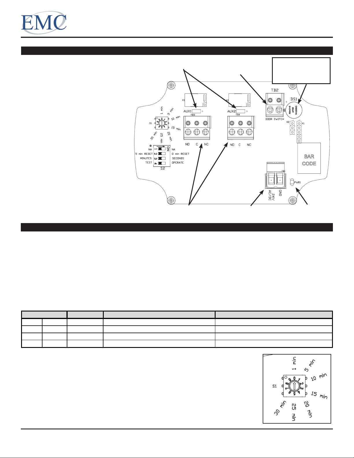
All terminal blocks are removable/
pluggable connectors.
14 to 22 AWG wire is required for all
connections.
Power: 24 VAC or 24 VDC
(UL Listed Class 2 Power Source only)
Door Switch: Connection is not
polarized.
Auxiliary Relays: Can be connected
as either normally open (NO) or
normally closed (NC).
Buzzer: Remove the cover sticker
prior to use.
Fig. 3: DMA -2.0
Circuit Board
Operation
Relay LEDs (red) Door Switch
Connection
Auxiliary Relay
Connections
Power Connection Power On
Remove
Sticker Prior
to Use!
LED (green)
Basic Operation:
When the door opens, the Door Switch input terminals create an open circuit. The Door Status LEDs on the face
of the unit will change color, both Auxiliary Relays will energize (providing dry contact outputs), and both Auxiliary
Relay LEDs will illuminate. If the door stays open longer than the Door Timer Interval setting, the buzzer will sound.
Closing the door will de-energize both of the Auxiliary Relays, silence the buzzer if it is on, and change the color of
the Door Status LEDs.
The Auxiliary Relays are energized whenever the door is open and de-energized whenever it is closed.
The Door Status LEDs on the face of the unit change colors depending on the conditions listed in the table below.
Door Status LEDs (located on the face of the unit)
Color
Green Solid Closed
Amber Flashing Open Door timer interval has not been exceeded. Close the door when completed with your work.
Amber Solid Closed 5 minute Buzzer Reset Interval has not expired. Avoid opening the door until the LEDs turn green.
Red Flashing Open Door timer interval exceeded. Close the door as soon as possible.
Door Internal Timer:
The user can select how long the door can be continuously open before the buzzer
sounds and the status LEDS turn red. Figure 4 shows the allowable settings. If the
switch is in one of the blank positions, it uses 1 min.
Door Status Additional Condition User Action
Fig. 4: Door Timer
Interval Rotary
Switch (S1)
Specications subject to change without notice.
Energy Management Consultants, 1550 La Follette Street, Fennimore, WI 53809
Tel. +1-608-822-3550 • Fax +1-608-822-3847 • E-mail: info@emccontrols.com • Web: www.emccontrols.com
2 of 4
Page 3

EMC-DMA-2.0
Rotary Switch
Power
Both Relay
Both Relays
Door Status
Buzzer
5 min
On
On
Energized
Flashing amber
Silent
15 min
On
Off
De-energized
Solid amber
Silent
Installation & Operating Instructions
43273_ins_DMA_2.0
Operation continued...
Buzzer Reset Interval - 0 min or 5 min RESET (Switch 2 of DIP Switch S2)
If the switch is set in the “ON” position, then the Reset = 0 minutes
and the buzzer timer resets immediately after the door is closed. This
essentially means that there is no waiting period before you should
open the door again. The buzzer will not sound again unless the door is
opened for longer than the Door Timer Interval rotary switch setting.
If the switch is set in the “OFF” position, then the Reset = 5 minutes
and the buzzer timer will not reset until the door has been closed for
more than 5 minutes. This means that if the door has been open for
longer than the Door Timer Interval rotary switch setting and the buzzer
sounds, then closing the door will silence the buzzer BUT NOT reset the
buzzer timer. The buzzer will immediately sound if the door is opened
any time within the next 5 minutes. Each time the door is opened during
this period, a new 5 minute “count down” period is started. The Door Status LEDs will change to green once the 5
minute period has expired.
Door Timer Interval - SECONDS or MINUTES (Switch 3 of DIP Switch S2)
Normal operation is set to “OFF” - MINUTES.
For a quick condence test, this switch can be set to SECONDS by placing it to the “ON” position. This means that
the buzzer will sound after 1 to 30 seconds (depending on the rotary switch settings) rather than 1 to 30 minutes.
This switch also changes the Buzzer Reset Interval from minutes to seconds (5 min RESET now equals 5 seconds
RESET).
Fig. 5: DIP Switches (S2)
rev. 04/15/19
Operational Test - OPERATE or TEST (Switch 4 of DIP Switch S2)
Used to test all of the output combinations of the DMA-2.0.
NOTE: The test mode disables door monitoring.
1. Set DIP switch (S2) to TEST.
2. Set rotary switch (S1) to the positions in the Operational Chart below to conrm that the unit’s output matches
those listed in the table.
3. Return the unit to normal operation by setting DIP switch to OPERATE and rotary switch (S1) to its intended time.
Operational Chart
(S1) Position
LED
LEDs
LEDs
1 min On Off De-energized Solid green Silent
10 min On On Energized Flashing red Sounding
20 min On Off De-energized Solid red Silent
25 min On Off De-energized All off Silent
Tel. +1-608-822-3550 • Fax +1-608-822-3847 • E-mail: info@emccontrols.com • Web: www.emccontrols.com
Specications subject to change without notice.
Energy Management Consultants, 1550 La Follette Street, Fennimore, WI 53809
3 of 4
Page 4

43273_ins_DMA_2.0
Diagnostics
EMC-DMA-2.0
Installation & Operating Instructions
rev. 04/15/19
Possible Problems:
Power LED (PWR1) does not light
Door Status LEDs indicate the
wrong status
Door Status LEDs do not change
Door Status LEDs do not come on
Possible Solutions:
Conrm that there is 24 VAC or 24 VDC at connector TB1 and that the
polarity is correct.
Make sure that the unit is in Operate mode, not Test mode (DIP Switch S2).
Conrm that the door switch is wired as a Normally Closed (NC) connection
(a closed door equals an open circuit).
Check for loose or shorted wires at the Door Switch connection.
Make sure that the unit is in Operate mode, not Test mode (DIP Switch S2).
Conrm that the unit is powered correctly. Power LED should be on.
Make sure that the unit is in Operate mode, not Test mode (DIP Switch S2).
Run the Operational Test described on page 3 to conrm that the LEDs,
relays or buzzer are not burned out.
Specications subject to change without notice.
Energy Management Consultants, 1550 La Follette Street, Fennimore, WI 53809
Tel. +1-608-822-3550 • Fax +1-608-822-3847 • E-mail: info@emccontrols.com • Web: www.emccontrols.com
4 of 4
 Loading...