

Page 1
EMC Departmental Switch
DS-xxB2
Guide for Installation of Switches
Into Third-Party Racks
P/N 300-000-267
November 7, 2002
This document describes the requirements for installing EMC
Deparmental Switches (DS-xxB2) into both EMC and non-EMC
third-party racks.
Rev. A02
Major sections discussed in this guide are as follows:
◆ Overview ................................................................................................2
◆ Device Power, Cooling, and Weight Information.............................3
◆ Device Dimensions................................................................................3
◆ Device Placement Requirements.........................................................4
◆ Switch Mounting Kit (DS16B2RKLS) .................................................5
◆ Installing the DS-xxB2 Rails.................................................................8
◆ Installing the DS-xxB2 Switch............................................................17
◆ Where to Get Help...............................................................................21
1
Page 2
Overview
1
Overview
The Departmental Switch Models DS-16B2 and DS-32B2 are fibre
channel gigabit switches that support link speeds up to 2 Gb/s. Each
port can automatically negotiate to the highest common speed of all
devices connected to the port. The ports are compatible with small
form factor pluggable media (SFPs), are universal, self configuring,
and are capable of individually becoming a fabric-enabled port
(F_Port), fabric loop enabled port (FL_Port), or an expansion port
(E_Port).
The Departmental Switch Model DS-16B2 is one rack unit in height,
has an air-cooled chassis, and can be set up as a stand-alone unit or
mounted in a 19-inch rack. The Departmental Switch Model DS-32B2
is an air-cooled 1.5U chassis; can be set up as a stand-alone unit or
mounted in a standard Electronic Industries Association (EIA)
19-inch rack.
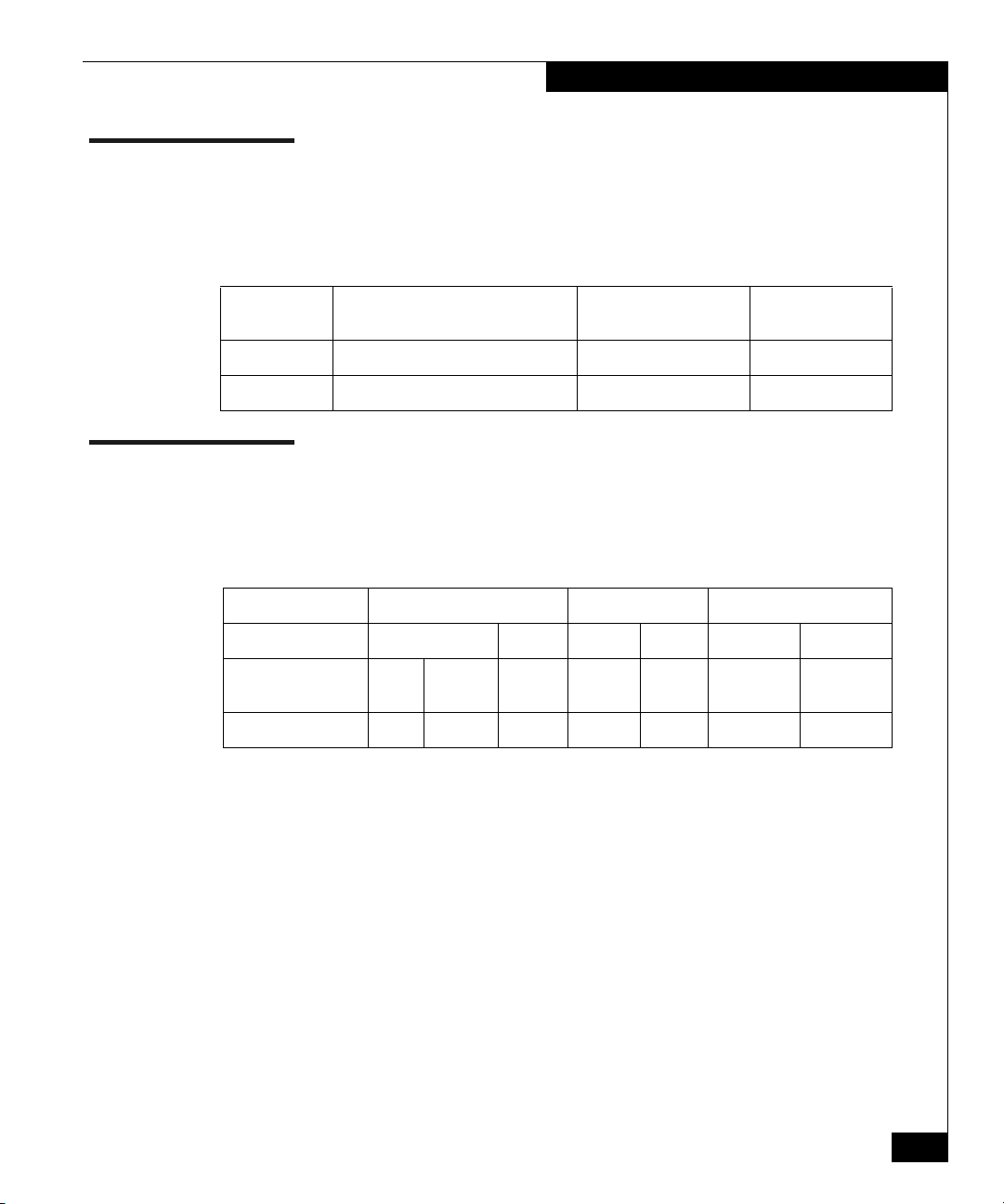
Table 1 lists the departmental switches and mounting kit model
numbers.
Table 1 Departmental Switch and Mounting Kit Model Numbers.
Device Device Model Mounting Kit Model
16-port Departmental Switch DS-16B2-00 DS16B2RKLS
32-port Departmental Switch DS-32B2-00 DS16B2RKLS
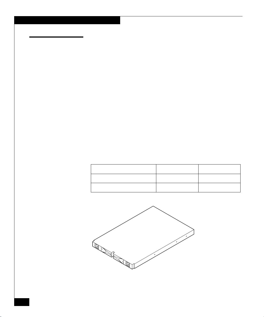
Figure 1 shows an example of the DS-xxB2.
EMC204
Figure 1 DS-xxB2
2
EMC Departmental Switch DS-xxB2 Into Third-Party Racks
Page 3
Device Power, Cooling, and Weight Information
Device Power, Cooling, and Weight Information
Table 2 lists the power and cooling requirements and weight
information for the DS-16B2 and DS32B2 switches.
Table 2 Device Power, Cooling, and Weight Information
Cooling Requirements
Device Power Requirements
DS-16B2 switch Voltage: 100 to 240 V ac, 47 to 63 Hz 368.5 BTU/hr 12.9 kg (28.5 lbs)
DS-32B2 switch Voltage: 100 to 240 V ac, 47 to 63 Hz 1876 BTU/hr 16.2 kg (35.8 lbs)
(Heat Dissipation) Maximum Weight
Device Dimensions
Table 3 gives the height, depth, and width for the DS-16B2 switch, the
DS-16B2 switch with rails, and the DS-32B2 switch
Table 3 Device Dimensions
Device Height Depth Width
DS-16B2 switch 4.34 cm 1.71 in 61.00 cm 24.01 in 42.86 cm 16.87 in
DS-16B2 switch
with rails
DS-32B2 switch 1.50 6.55 cm 2.58 in 58.56 cm 23.06 in 42.86 cm 16.87 in
1.0 U 4.44 cm 1.75 in 61.00 cm 24.01 in 43.18 cm 17.00 in
EMC Departmental Switch DS-xxB2 Into Third-Party Racks
3
Page 4
Device Placement Requirements
Device Placement Requirements
There are no restrictions on the location of the DS-xxB2 switch in the
rack/cabinet.
Switches are typically located at the top of the rack/cabinet.
Power distribution must support the number of outlets required for
the switch and the switch power rating listed in Table 2 on page 3.
Front Rear
EMC2056S
Figure 2 Sample Cabinet Installation
4
EMC Departmental Switch DS-xxB2 Into Third-Party Racks
Page 5
Switch Mounting Kit (DS16B2RKLS)
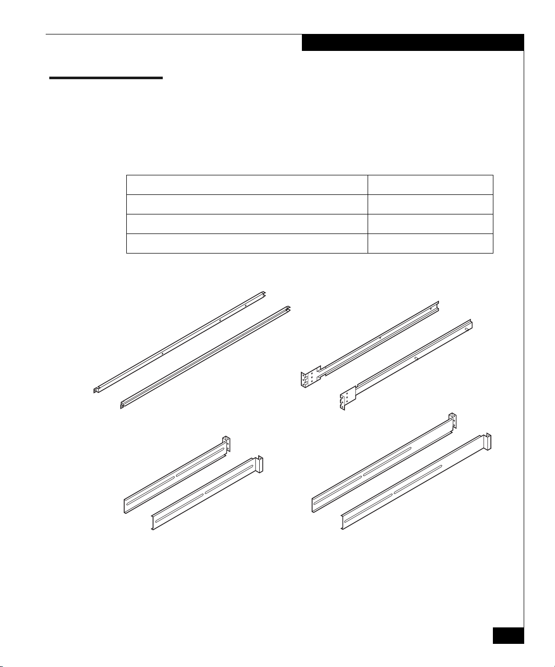
The switch mounting kit includes rails, and brackets as listed inTable
4.
Table 4 Switch Mounting Kit
Component Use
2 switch mounting brackets (see Figure 15 on page 17) 2 per switch
2 short rail assemblies (20.5 inches to 27 inches) 2 per switch
2 long rail assemblies (27 inches to 34 inches) 2 per switch
Figure 3 illustrates these components.
Switch Mounting Kit (DS16B2RKLS)
Switch
Mounting
Brackets
Short
Rear
Rails
Figure 3 Rails and Brackets
EMC Departmental Switch DS-xxB2 Into Third-Party Racks
Front
Rails
Long
Rear
Rails
EMC2042S
5
Page 6
Switch Mounting Kit (DS16B2RKLS)
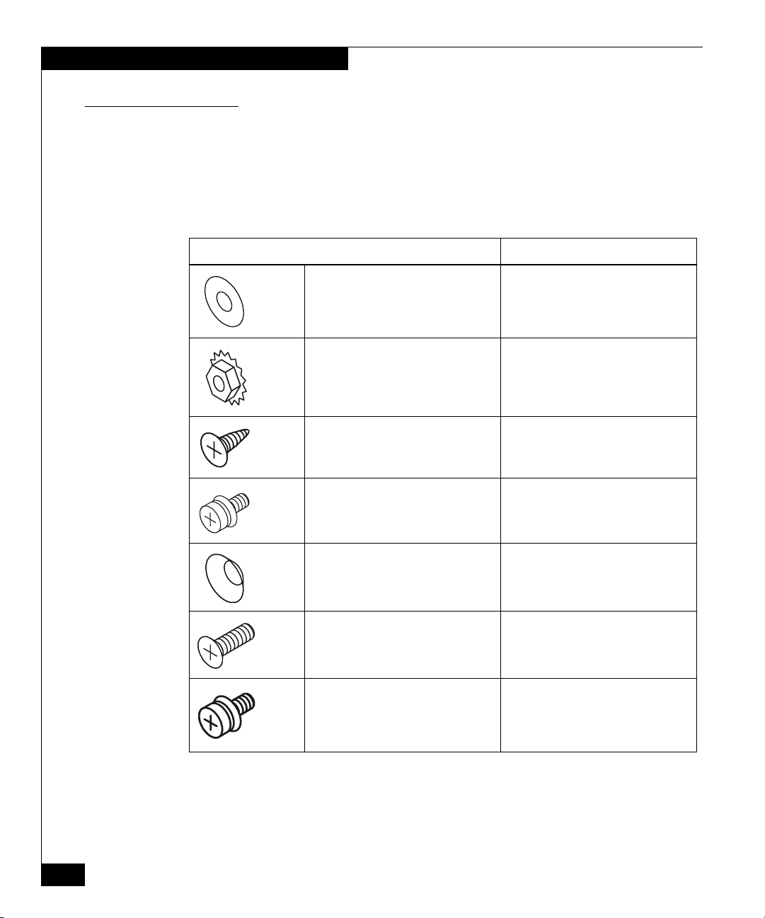
Screws, Nuts and Washers
Table 5 Screws, Nuts and Washers
Component Use
Table 5 lists all the securing hardware that is included in the switch
mounting kit.
#10 flat washer (Qty. 4) 2 per rail assembly to secure adjustable
rail to the “C” channel.
M5 keps nut (Qty. 4) 2 per rail assembly to secure adjustable
rail to the “C” channel.
8-32 x 5/16-in. pan-head screw (Qty. 6) 3 per mounting bracket to secure
mounting bracket to switch.
M5 x 10-mm pan-head screw (Qty. 8) 4 per rail for DS-16B2 in round-hole
channels.
Square-hole washer (Qty. 8) 4 per rail for DS-16B2 in square-hole
channels.
M5 x 16-mm flat-head screw (Qty. 8) 4 per rail for DS-16B2 in square-hole
channels.
M3 x 8-mm pan-head screw (Qty. 2) 1 per switch mounting bracket. Used to
secure mounting brackets to the rails.
6
EMC Departmental Switch DS-xxB2 Into Third-Party Racks
Page 7
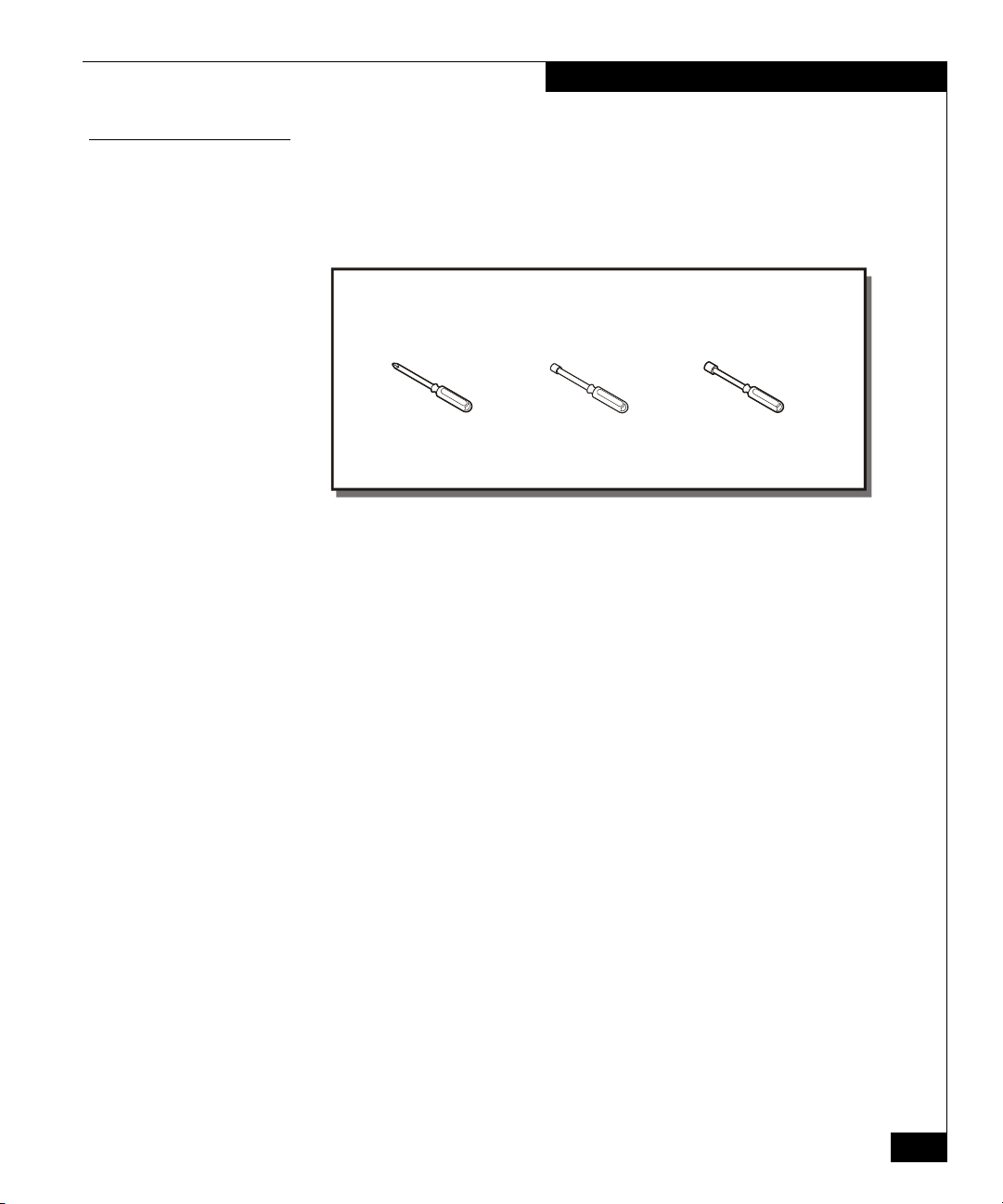
Tools Required for Installation
You will need the tools shown in Figure 4 to complete the installation
of the rails and one or more switches.
Switch Mounting Kit (DS16B2RKLS)
Tools Required:
#1 Phillips
Screwdriver
Figure 4 Tools Required for Installation
6-mm (1/4-in.)
Nut Driver
8mm (5/16-in.)
Nut Driver
EMC2065
EMC Departmental Switch DS-xxB2 Into Third-Party Racks
7
Page 8

Installing the DS-xxB2 Rails
Installing the DS-xxB2 Rails
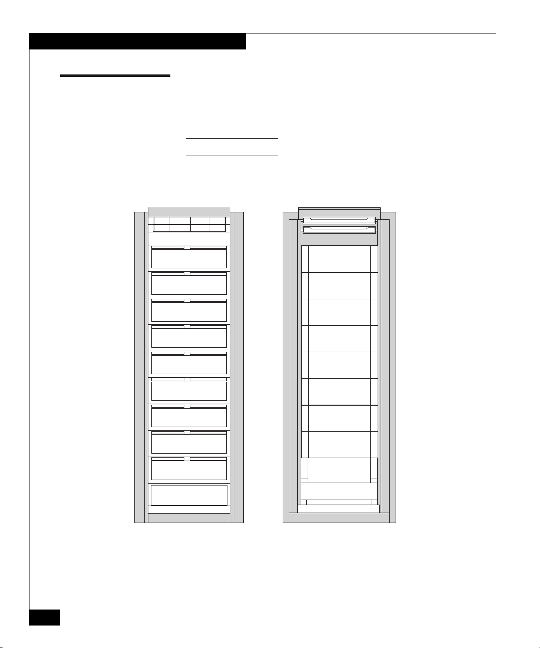
This section describes the installation procedures for the DS-xxB2
rails. Figure 5 shows a view of the rails installed in a 39 U
rack/cabinet.
Rear Door
Removed for
Clarity
Front
Figure 5 View of the Rails Installed in a 39 U Rack/Cabinet
8
EMC Departmental Switch DS-xxB2 Into Third-Party Racks
Rear
EMC2071S
Page 9

DS-xxB2 Rails Installation
9
t
0
To the rear
t
Figure 6 DS-xxB2 Short Rear Rails
Installing the DS-xxB2 Rails
There are two different length rails, see Figures 6 and 7. The short
rails range between 20.5 inches and 27 inches. The long rails range
between 27 inches and 34 inches. If your rail kit contains two different
length rear rail mounts, be sure to use the rail length that is
appropriate for your rack/cabinet.
To the rear
of the cabine
EMC205
Figure 7 DS-xxB2 Long Rear Rails
EMC Departmental Switch DS-xxB2 Into Third-Party Racks
of the cabine
EMC206
9
Page 10

Installing the DS-xxB2 Rails
9
0
Screw
Hol es
ails
Scr ew
Hol es
The front and rear flanges of the DS-xxB2 rails have three screw holes.
See Figures 8 and 9.
Screw
Hol es
Figure 8 Front Flange of the DS-xxB2 Rails
Short
Rear
Rai ls
Fr ont
Rai ls
EMC206
10
Long
Rear
R
Figure 9 Rear Flange of the DS-xxB2 Rails
EMC Departmental Switch DS-xxB2 Into Third-Party Racks
EMC207
Page 11

Keps Nut
(2)
#10 Flat
Washer
(2)
Short
Rear
Rail
Front
Rail
Installing the DS-xxB2 Rails
Select the appropriate length rails, and follow the steps below to
install them. The rails assembly consists of a front rail, an adjustable
rear rail, and two washers and keps nuts. Figure 10 illusrates the
complete assembly.
Figure 10 DS-xxB2 Rails Assembly
EMC Departmental Switch DS-xxB2 Into Third-Party Racks
Front
Rail
Short
Rear
Rail
#10 Flat
Washer
(2)
Keps Nut
(2)
EMC2044S
11
Page 12

Installing the DS-xxB2 Rails
Assembling the Rails
To assemble the rails:
1. Place the front rail down on a table.
2. Insert the slots of the rear adjustable rail onto the threaded posts
on the front rail. Be sure that the lip on the top of the rear
adjustable rail slides over the top of the slot on the front rail,
thereby capturing the ac power cord.
3. Secure the adjustable rail to the front rail with two #10 flat
washers and M5 keps nuts. Leave the keps nuts finger tight (see
Figure 11).
Keps
Nut
EMC2066S
12
Figure 11 Location of Keps Nuts
4. Determine where in the rack/cabinet you will locate the switch.
5. Adjust the length of the rail to fit between the channels in the
rack/cabinet.
EMC Departmental Switch DS-xxB2 Into Third-Party Racks
Page 13

Keps
Nut
Figure 12 Securing the Keps Nuts
If the side skins are removed on the rack/cabinet, the keps nuts can be
tightened after the rails have been installed.
Installing the DS-xxB2 Rails
Keps
Nut
EMC2045S
Round-Hole Channel
To install the rails assembly in the round-hole channel of the
rack/cabinet:
1. Align the holes of the front rail flange to the inside of the front
channel. The top and bottom screw holes are used for the screws.
2. Secure the rail to a round-hole channel with 2 M5 x 10-mm panhead screws (see table on Table 5 on page 6). Leave the screws
finger-tight, and tighten them after the switch is installed. See
Figure 13 on page 14.
3. Align the holes in the rear, U-shaped flange of the rail with the
holes in the rear inside channel.
4. Secure the rail to a round-hole channel with 2 M5 x 10-mm panhead screws (see table on Table 5 on page 6). Leave the screws
finger-tight, and tighten them after the switch is installed. See
Figure 13.
5. Repeat steps 1 through 4 for the other rail.
See instructions for Square-Hole Channel on page 15.
EMC Departmental Switch DS-xxB2 Into Third-Party Racks
13
Page 14

Installing the DS-xxB2 Rails
Rack
Front
Align the front rail
flange to the inside
of the channel.
Align the rear rail
flange to the inside
of the channel.
Rack
Rear
Rear
14
M5 x 10-mm
Pan Head
Screw
(8)
Front
EMC2046S
Figure 13 Installing Rails in Round-Hole Channels
EMC Departmental Switch DS-xxB2 Into Third-Party Racks
Page 15

Square-Hole Channel
Installing the DS-xxB2 Rails
To install the rails assembly in the square-hole channel of the
rack/cabinet.
1. Align the holes of the front rail flange to the inside of the front
channel. The top and bottom screw holes are used for the screws
(see Figure 14 on page 16).
2. Secure the rail to a square-hole channel with two square-hole
washers and M5 x 16-mm flat-head screws (see Table 5 on
page 6). Leave the screws finger-tight, and tighten them after the
switch is installed.
3. Align the holes in the rear, U-shaped flange of the rail with the
holes in the rear inside channel, as shown in Figure 14.
4. Secure the rail to a square-hole channel with two square-hole
washers and M5 x 16-mm flat head screws (see Table 5 on page 6).
Leave the screws finger-tight, and tighten them after the switch is
installed.
5. Repeat steps 1 through 4 for the other rail.
See instructions for Round-Hole Channel on page 13.
EMC Departmental Switch DS-xxB2 Into Third-Party Racks
15
Page 16

Installing the DS-xxB2 Rails
S
Rack
Rear
Align the rear rail
flange to the inside
of the channel.
Rack
Front
M5 x 16-mm
flat head screw
(Qty. 8)
Square-Hole
Washer
(Qty. 8)
Align the front rail
flange to the inside
of the channel.
EMC2047
Figure 14 Installing Rails in Square-Hole Channels
16
EMC Departmental Switch DS-xxB2 Into Third-Party Racks
Page 17

Installing the DS-xxB2 Switch
8
Moun ti ng
This section describes the procedures for installing the DS-xxB2
switch in a rack/cabinet, including attaching the brackets on the
switch.
Mounting Bracket Installation
You must attach mounting brackets to the switch before installing it
on the rails. The mounting brackets slide into the “C” channel of the
rails.
To attach the mounting brackets to the switch:
1. Orient the L-shaped end of the bracket outward and to the power
outlet end of the switch.
2. Place the bracket against the switch. Align the three screw holes
in the bracket with three screw holes on the side of the switch (see
Figure 15 on page 17).
3. Secure the bracket with three 8-32 x 5/16-in. pan-head screws (see
Table 5 on page 6). Tighten the screws fully.
Installing the DS-xxB2 Switch
4. Repeat steps 1 through 3 for the other side of the switch to be
mounted.
#8-32 x 5/16-in.
Pan Head Screw
Swit ch
Mounting
Bracket
Figure 15 Attaching the Switch Mounting Brackets
(6)
Hol e
EMC Departmental Switch DS-xxB2 Into Third-Party Racks
Swit ch
Bracket
EMC204
17
Page 18

Installing the DS-xxB2 Switch
Installing the Switch in the Rack/Cabinet
To install the switch in the rack/cabinet:
1. Lift and orient the switch so that the fan end is to the front of the
rack/cabinet.
2. Align the bracket on each side of the switch with the “C” channel
on each fixed rail.
3. Push the switch into the rack/cabinet until the hole in the front
part of each bracket (the “L”-shaped end) aligns with the hole on
the fixed rail.
18
EMC2049S
Figure 16 Placing the Switch Into the Rack/Cabinet
4. Secure the brackets to the rails with two M3 x 8-mm pan-head
screws (see Table 5 on page 6), one on each side, (Figure 17 on
page 19).
EMC Departmental Switch DS-xxB2 Into Third-Party Racks
Page 19

M3 x 8-mm
Pan Head
Screw
(2)
Figure 17 Securing the brackets to the Rails
Installing the DS-xxB2 Switch
EMC2050S
5. Tighten the rear screws securing the rails to the rear of the
rack/cabinet (see Figure 18 on page 20).
6. Tighten the front screws securing the rails to the front of the
rack/cabinet (see Figure 18).
EMC Departmental Switch DS-xxB2 Into Third-Party Racks
19
Page 20

Installing the DS-xxB2 Switch
Figure 18 Tightening the Front and Rear Rail Assembly Screws
Rail
Assembly
Screw
(4)
Rail Assembly
Screw
(4)
EMC2051S
20
EMC Departmental Switch DS-xxB2 Into Third-Party Racks
Page 21

Where to Get Help
Where to Get Help
For questions about technical support call your local sales office or
service provider.
If you have a valid EMC service contract, contact EMC Customer
Service at:
United States: (800) 782-4362 (SVC-4EMC)
Canada: (800) 543-4782 (543-4SVC)
Worldwide: (508) 497-7901
Follow the voice menu prompts to open a service call and select the
applicable product support.
If you are located outside the North America, call the nearest EMC
office for technical assistance.
Sales and Customer
Service Contacts
For the list of EMC sales locations, please access the EMC home page
at:
http://www.EMC.com/contact/
For additional information on the EMC products and services
available to customers and partners, refer to the EMC Powerlink
website at:
http://powerlink.EMC.com
Your Comments Your suggestions will help us continue to improve the accuracy,
organization, and overall quality of the user publications. Please send
a message to techpub_comments@EMC.com with your opinions of
this guide.
EMC Departmental Switch DS-xxB2 Into Third-Party Racks
21
Page 22

Where to Get Help
Copyright © 2002 EMC Corporation. All Rights Reserved.
EMC believes the information in this publication is accurate as of its publication date. The information is subject to
change without notice.
THE INFORMATION IN THIS PUBLICATION IS PROVIDED "AS IS." EMC CORPORATION MAKES NO
REPRESENTATIONS OR WARRANTIES OF ANY KIND WITH RESPECT TO THE INFORMATION IN THIS
PUBLICATION, AND SPECIFICALLY DISCLAIMS IMPLIED WARRANTIES OF MERCHANTABILITY OR
FITNESS FOR A PARTICULAR PURPOSE.
Use, copying, and distribution of any EMC software described in this publication requires an applicable software
license.
22
EMC Departmental Switch DS-xxB2 Into Third-Party Racks
 Loading...