

Page 1
EMC Enterprise Storage
Departmental Switch
Models DS-16B and DS-8B
Web Tools
Version 2.3
USER GUIDE
P/N 069001083-00
EMC Corporation 171 South Street, Hopkinton, MA 01748-9103
Corporate Headquarters: (508) 435-1000, (800) 424-EMC2 Fax: (508) 435-5374 Service: (800) SVC-4EMC
Page 2

Copyright © 2001 EMC Corporation. All rights reserved.
Printed March 2001
No part of this publication may be reproduced or distributed in any form or by any means, or stored in a
database or retrieval system, without the prior written consent of EMC Corporation.
The information contained in this document is subject to change without notice. EMC Corporation assumes
no responsibility for any errors that may appear.
All computer software programs, including but not limited to microcode, described in this document are
furnished under a license, and may be used or copied only in accordance with the terms of such license.
EMC either owns or has the right to license the computer software programs described in this document.
EMC Corporation retains all rights, title and interest in the computer software programs.
EMC Corporation makes no warranties, expressed or implied, by operation of law or otherwise, relating to
this document, the products or the computer software programs described herein. EMC CORPORATION
DISCLAIMS ALL IMPLIED WARRANTIES OF MERCHANTIBILITY AND FITNESS FOR A PARTICULAR
PURPOSE. In no event shall EMC Corporation be liable for (a) incidental, indirect, special, or consequential
damages or (b) any damages whatsoever resulting from the loss of use, data or profits, arising out of this
document, even if advised of the possibility of such damages.
Regulatory Agency Certification
Connectrix DS-16B and DS-8B has been extensively tested and certified to met UL1950, CSA 950, IEC
950/EN 60950 Safety of Information Technology Equipment Including Electrical Business Equipment; FCC
Rules Part 15 Subpart B; CISPR22 Class A; EN55022; EN50082-1.
Canada:
This class A digital apparatus complies with Canadian ICES-003.
Cet appareil numérique de la classe A est conforme à la norme NMB-003 du Canada.
Europe:
Warning!
This is a Class A product. In a domestic environment this product may cause radio interference in which
case the user may be required to take adequate measures.
Achtung!
Dieses ist ein Gerät der Funkstörgrenzwertklasse A. In Wohnbereichen können bei Betrieb dieses Gerätes
Rundfunkstörungen auftreten, in welchen Fällen der Benutzer für entsprechende Gegenmaßnahmen
verantwortlich ist.
Attention!
Ceci est un produit de Classe A. Dans un environnement domestique, ce produit risque de créer des
interférences radioélectriques, il appartiendra alors à l'utilisateur de prendre les mesures spécifiques
appropriées.
ii
Departmental Switch Models DS-16B and DS-8B Web Tools User Guide
Page 3

Japan:
United States:
This equipment generates, uses, and may emit radio frequency energy. The equipment has been type tested
and found to comply with the limits for a Class A digital device pursuant to Part 15 of FCC rules, which are
designed to provide reasonable protection against such radio frequency interference.
Operation of this equipment in a residential area may cause interference in which case the user at his own
expense will be required to take whatever measures may be required to correct the interference.
Any modifications to this device - unless expressly approved by the manufacturer - can void the user’s
authority to operate this equipment under part 15 of the FCC rules.
Taiwan:
Trademark Information
EMC2, EMC, MOSAIC:2000, and Symmetrix are registered trademarks and EMC Enterprise Storage, The Enterprise Storage Company, The EMC Effect,
Connectrix, EDM, SDMS, SRDF, TimeFinder, PowerPath, InfoMover, FarPoint, EMC Enterprise Storage Network, EMC Enterprise Storage Specialist,
EMC Storage Logic, Universal Data Tone, E-Infostructure, and Celerra are trademarks of EMC Corporation.
Internet Explorer, Windows are registered trademarks of Microsoft Corporation.
Netscape and Communicator are registered trademarks of Netscape.
Java Plug-in on Sun, Solaris are registered trademarks of Sun Microsystems.
All other trademarks used herein are the property of their respective owners.
Departmental Switch Models DS-16B and DS-8B Web Tools User Guide
iii
Page 4

iv
Departmental Switch Models DS-16B and DS-8B Web Tools User Guide
Page 5

Contents
Preface............................................................................................................................. xi
Chapter 1 Introducing Web Tools
Overview........................................................................................... 1-2
Web Tools Views............................................................................... 1-3
Chapter 2 Installing Web Tools
Requirements.................................................................................... 2-2
Switch Requirements................................................................ 2-2
Workstation Requirements...................................................... 2-2
Installation ........................................................................................ 2-3
Web Tools................................................................................... 2-3
Additional Software................................................................. 2-3
Installing a Web Browser......................................................... 2-3
Configuring the Web Browser ................................................ 2-3
Installing the Java Plug-in on the Workstation..................... 2-5
Chapter 3 Using Web Tools
Fabric View....................................................................................... 3-2
Fabric Events View .......................................................................... 3-7
Fabric Topology View...................................................................... 3-9
Name Server Table View............................................................... 3-13
Zone Administration View........................................................... 3-16
Alias Tab................................................................................... 3-18
Zone Tab................................................................................... 3-20
QuickLoop Tab........................................................................ 3-22
Fabric Assist Tab ..................................................................... 3-24
Config Tab................................................................................ 3-27
Departmental Switch Models DS-16B and DS-8B Web Tools User Guide
v
Page 6

Contents
Switch View.................................................................................... 3-29
Switch Events View....................................................................... 3-33
Port Information View .................................................................. 3-35
PortStats Tab ........................................................................... 3-38
GBIC Tab.................................................................................. 3-40
Loop Tab .................................................................................. 3-43
Fabric Watch View......................................................................... 3-48
Alarm Notifications Tab ........................................................ 3-49
Configure Thresholds............................................................ 3-50
Current Settings Tab............................................................... 3-54
Performance View.......................................................................... 3-55
Chapter 4 Administrative Interface
Administrative Interface................................................................. 4-2
Switch Administration.................................................................... 4-4
User Administration........................................................................ 4-7
Reboot Switch ........................................................................... 4-9
SNMP Administration .................................................................. 4-11
License Administration................................................................. 4-13
Remote Switch................................................................................ 4-14
QuickLoop Administration.......................................................... 4-16
Config Admin Tab......................................................................... 4-18
Switch Information Report.................................................... 4-19
Extended Fabric Tab (Optional Software).................................. 4-21
Telnet Interface............................................................................... 4-23
Appendix A Customer Support
Support Tool ................................................................................... A-2
Overview of Detecting and Resolving Problems ...................... A-3
Troubleshooting the Problem ....................................................... A-4
Before Calling the Customer Support Center ............................ A-5
Documenting the Problem ........................................................... A-6
Reporting a New Problem ............................................................ A-7
Sending Problem Documentation ............................................... A-8
Glossary ........................................................................................................................ g-1
Index................................................................................................................................ i-1
vi
Departmental Switch Models DS-16B and DS-8B Web Tools User Guide
Page 7

Figures
3-1 Fabric View .................................................................................................... 3-3
3-2 Summary Version — Fabric View .............................................................. 3-6
3-3 Fabric Events View ....................................................................................... 3-7
3-4 Fabric Topology View ................................................................................ 3-10
3-5 Fabric Topology View, Scrolled Downwards ........................................ 3-11
3-6 Name Server Table View ........................................................................... 3-13
3-7 Alias Tab — Zone Administration View ................................................ 3-18
3-8 Zone Tab — Zone Administration View ................................................. 3-20
3-9 QuickLoop Tab — Zone Administration View ...................................... 3-22
3-10 Fabric Assist Tab — Zone Administration View ................................... 3-24
3-11 Config Tab — Zone Administration View .............................................. 3-27
3-12 Switch View ................................................................................................. 3-29
3-13 Switch Events View .................................................................................... 3-33
3-14 Port Information View ............................................................................... 3-35
3-15 PortStats Tab — Port Information View ................................................. 3-38
3-16 GBIC Tab — Port Information View ........................................................ 3-40
3-17 Loop Tab — Port Information View ........................................................ 3-43
3-18 Loop Diagnostics Dialog Box .................................................................... 3-45
3-19 LIP Dialog Box ............................................................................................ 3-46
3-20 Bypass Dialog Box ...................................................................................... 3-46
3-21 Enable Dialog Box ...................................................................................... 3-47
3-22 Alarm Notifications Tab — Fabric Watch View .................................... 3-49
3-23 Configure Threshold Tab with Environment Class Selected ............... 3-50
3-24 Configure Threshold Tab with Port Class Selected ............................... 3-53
3-25 Current Settings Tab — Fabric Watch View ........................................... 3-54
3-26 Performance View ...................................................................................... 3-55
4-1 Enter Network Password ............................................................................ 4-3
4-2 Switch Administration ................................................................................. 4-4
4-3 User Administration .................................................................................... 4-7
4-4 Firmware Upgrade ....................................................................................... 4-8
Departmental Switch Models DS-16B and DS-8B Web Tools User Guide
vii
Page 8

Figures
4-5 Reboot Switch ................................................................................................ 4-9
4-6 SNMP Administration ................................................................................ 4-11
4-7 License Administration .............................................................................. 4-13
4-8 Remote Switch ............................................................................................. 4-15
4-9 QuickLoop Administration ....................................................................... 4-16
4-10 Config Admin Tab ...................................................................................... 4-18
4-11 Switch Information Report ........................................................................ 4-20
4-12 Extended Fabric Tab ................................................................................... 4-21
4-13 Initiating a Telnet Session .......................................................................... 4-23
4-14 Telnet Session in Use .................................................................................. 4-23
A-1 Problem Detection and Resolution Process .............................................. A-3
viii
Departmental Switch Models DS-16B and DS-8B Web Tools User Guide
Page 9

Tables
1-1 Web Tools Views .......................................................................................... 1-3
3-1 Fabric View Components ............................................................................ 3-3
3-2 Fabric Events Columns ................................................................................ 3-8
3-3 Fabric Topology View ................................................................................ 3-11
3-4 Name Server Table View Fields ............................................................... 3-14
3-5 Name Server Table View Columns .......................................................... 3-14
3-6 Adding Members to a Zone ...................................................................... 3-16
3-7 Alias Tab Fields ........................................................................................... 3-18
3-8 Zone Tab Fields ........................................................................................... 3-20
3-9 QuickLoop Tab Fields ................................................................................ 3-22
3-10 Fabric Assist Tab Fields ............................................................................. 3-25
3-11 Config Tab Fields ........................................................................................ 3-27
3-12 Switch View ................................................................................................. 3-30
3-13 Switch Events .............................................................................................. 3-34
3-14 Port Information Fields .............................................................................. 3-36
3-15 PortStats Tab Fields .................................................................................... 3-38
3-16 GBIC Tab Fields .......................................................................................... 3-41
3-17 Loop Fields .................................................................................................. 3-43
3-18 Loop Diagnostics Fields ............................................................................. 3-46
3-19 LIP Fields ..................................................................................................... 3-46
3-20 Bypass Fields ............................................................................................... 3-47
3-21 Enable Fields ............................................................................................... 3-47
3-22 Environmental and GBIC Classes Thresholds ....................................... 3-51
3-23 Additional Port Class Thresholds ............................................................ 3-52
4-1 Switch Administration Tab ......................................................................... 4-5
4-2 User Administration Fields ......................................................................... 4-7
4-3 Firmware Upgrade Tab ............................................................................... 4-8
4-4 Reboot Switch Fields .................................................................................. 4-10
4-5 SNMP Administration Fields ................................................................... 4-12
4-6 License Administration Fields .................................................................. 4-14
Departmental Switch Models DS-16B and DS-8B Web Tools User Guide
ix
Page 10

Tab les
4-7 Remote Tab Fields ....................................................................................... 4-15
4-8 QuickLoop Administration Fields ............................................................ 4-17
4-9 Config Admin Tab ...................................................................................... 4-19
4-10 Extend Fabric Fields .................................................................................... 4-22
x
Departmental Switch Models DS-16B and DS-8B Web Tools User Guide
Page 11

Preface
This guide describes Web Tools and provides installation instructions
as well as detailed information for using each function.
Audience This guide is part of the Department Switch Models DS-16B and
DS-8B documentation set, and is intended for use by Customer
Engineers and Switch Administrators.
Organization Here is an overview of where information is located in this guide.
This Preface provides information on related publications, getting
help, and getting software updates.
Chapter 1, Introducing Web Tools, provides an overview of Web Tools
and a summary of the information available through Web Tools.
Chapter 2, Installing Web Tools, describes the system requirements and
instructions for installing and launching Web Tools.
Chapter 3, Using Web Tools, provides information about and
instructions for using each of the windows in Web Tools.
Chapter 4, Administrative Interface, provides information about and
instructions for using each of the windows in Web Tools.
Appendix A, Customer Support, provides essential questions that a
customer should be prepared to answer when contacting the EMC
Customer Support Center.
The Glossary provides a glossary of related terms used with switches.
Departmental Switch Models DS-16B and DS-8B Web Tools User Guide
xi
Page 12
Preface
Related Publications Other publications that provide related information are:
◆ Departmental Switch Models DS-16B and DS-8B Fabric OS version
2.2, P/N 069001028
◆ Departmental Switch Model DS-16B QuickLoop version 2.2 Reference
Manual, P/N 069001027-01
Conventions Used in
this Manual
!
EMC uses the following conventions for notes, cautions, warnings,
and danger notices.
A note presents information that is important, but not hazard-related.
CAUTION
A caution contains information essential to avoid damage to the
system or equipment. The caution may apply to hardware or
software.
WARNING
A warning contains information essential to avoid a hazard that can
cause severe personal injury, death, or substantial property damage
if you ignore the warning.
DANGER
A danger notice contains information essential to avoid a hazard
that will cause severe personal injury, death, or substantial property
damage if you ignore the warning.
EMC uses the following type style conventions in this guide:
xii
Palatino,
bold
◆ Dialog box, button, icon, and menu items in text
◆ Selections you can make from the user interface,
including buttons, icons, options, and field
names
Palatino,
italic
Departmental Switch Models DS-16B and DS-8B Web Tools User Guide
◆ New terms or unique word usage in text
◆ Command line arguments when used in text
◆ Book titles
Page 13

Preface
Courier,
italic
Courier
Arguments used in examples of command line
syntax.
System prompts and displays and specific
filenames or complete paths. For example:
working root directory [/user/emc]:
c:\Program Files\EMC\Symapi\db
Courier,
bold
User entry. For example:
symmpoll -p
Where to Get Help Obtain technical support by calling your local sales office.
For service, call:
United States: (800) 782-4362 (SVC-4EMC)
Canada: (800) 543-4782 (543-4SVC)
Worldwide: (508) 497-7901
and ask for Customer Support.
Your Comments Your suggestions will help us continue to improve the accuracy,
organization, and overall quality of the user publications. Please send
a message to techpub_comments@emc.com with your opinions of
this guide.
Departmental Switch Models DS-16B and DS-8B Web Tools User Guide
xiii
Page 14

Preface
xiv
Departmental Switch Models DS-16B and DS-8B Web Tools User Guide
Page 15

Invisible Body Tag
1
Introducing Web Tools
◆ Overview.............................................................................................1-2
◆ Web Tools Views.................................................................................1-3
Introducing Web Tools
1-1
Page 16

Introducing Web Tools
1
Overview
Web Tools provides a graphical interface that enables you to monitor
and manage entire fabrics and individual switches and ports from a
standard workstation.
Web Tools provides the following information and capabilities:
◆ Monitoring of and the ability to manage the entire fabric:
• The status of all switches in the fabric.
• Access to event logs for entire fabric
• Zoning functions
• Access to the Name Server Table
• Telne t func tions
• Switch beaconing for rapid identification in large fabric
environments
• Loop diagnostics and query and control of loop interfaces to
aid in locating faulty devices
• Ability to name and zone QuickLoops™
◆ Monitoring of and the ability to manage individual switches:
• Summary information about each switch
• Access to event logs for individual switches
• Switch configuration and administration
• Ability to upgrade Fabric OS and license key administration
• Report capability for switch configuration information
◆ Monitoring of and the ability to manage individual ports:
1-2
• Port status
• Information about GBIC (Gigabit Interface Converter) Serial
IDs
• Information about connected devices
• Loop information
• Port performance including frame counts (frames in, frames
out) and error counts
Departmental Switch Models DS-16B and DS-8B Web Tools User Guide
Page 17
Web Tools Views
Table 1-1 Web Tools Views
Initial Display Upon Launching Web Tools:
Fabric View Displays a control panel that provides access to fabric-wide options,
Introducing Web Tools
1
Web Tools provides access to and information about the fabric
through a number of separate windows, making it possible to view
several aspects of the fabric at the same time (Table 1-1).
a panel for each switch in the fabric, plus a legend that explains the
meaning of the background colors on the Switch icons. Each panel
contains an icon that represents the switch itself, in addition to icons
for Switch Events and the Administrative and Telnet interfaces. The
background color of the switch icon represents the status of that
particular switch or Integrated Fabric (as defined by the legend
provided in the window).
Switch status is calculated approximately once per second; however the
initial calculation does not occur until 30-60 seconds after the switch is
booted. It is calculated from the state of data structures in the switch,
and stored as the variable switchStatus.
For all statuses that are based on errors per time interval, any errors
will cause the status to show faulty until the entire sample interval
has passed.
Accessible from Fabric View:
Fabric Events
View
Displays the error log for the fabric, which is the combination of the
error logs of all the switches in the fabric. Accessed by clicking on
the Fabric Events icon on the control panel.
Fabric Topology
View
Displays physical configuration, including active domains, paths,
and routing information. Accessed by clicking on the Fabric
Topology icon on the control panel.
Name Server
Table Vi ew
Displays the Name Server Table for the fabric. Use to view
information about the devices attached to the fabric. Accessed by
clicking on the Name Server icon on the control panel.
Web Tools Views
1-3
Page 18

Introducing Web Tools
1
Table 1-1 Web Tools Views (continued)
Zone
Administration
View
Summary
Provides an interface to Zoning, including zone settings, zone
aliases, QuickLoops, Fabric Assists, and zone configurations.
Accessed by clicking on the Zone Admin icon on the control panel.
Toggles between summarized and detailed versions of Fabric View.
View/Detail View
Switch View Displays information about individual switches, including a
real-time view of switch status. Accessed by clicking on the Switch
icon on a switch panel. The Switch View is also the launch point for
the Switch Events View, Telnet Interface, Fabric Watch View,
Administrative Interface, Performance View, and Port Information
View. It includes icons that display the status of the switch fans,
temperature monitors, and beacon.
Switch Events
View
Displays the error log for the switch. Accessed by clicking on the
Events icon on the switch panel. This view can also be accessed
through Switch View (see Switch Events View on page 1-5).
Telnet Interface Provides an interface for using Telnet commands for switch
diagnostics, troubleshooting, and fabric management. Accessed by
clicking on the Te l n e t icon on the switch panel. This view can also be
accessed through Switch View (see Telnet Interface on page 1-5).
Administrative
Interface
Provides an interface for performing functions such as upgrading
firmware versions or reconfiguring a switch. Accessed by clicking
on the Admin icon on the switch panel. This view can also be
accessed through Switch View (see Administrative Interface on
page 1-5).
1-4
Departmental Switch Models DS-16B and DS-8B Web Tools User Guide
Page 19
Table 1-1 Web Tools Views (continued)
Accessible From Switch View (continued):
Introducing Web Tools
1
Port Information
View
Displays statistics and status for the selected port, GBIC, or loop.
Also provides options for managing loops. Accessed by clicking on
the icon for the relevant port in Switch View.
Power Supply
Status
The Power Supply icons on the switch graphic indicate the number
of power supplies present, and the LED on the power supply
indicates the status of the power assemblies.
Switch Events
View
Displays the error log for the switch. Accessed by clicking on Events
in Switch View. This view can also be accessed through Fabric View
(see Fabric View on page 1-3).
Telnet Interface Provides an interface for using Telnet commands for switch
diagnostics, troubleshooting, and detailed fabric management.
Accessed by clicking on Te l n e t in Switch View. This view can also be
accessed through Fabric View (see Fabric View on page 1-3).
Fabric Watch
View
Monitors fabric elements and displays error and performance
counter status, issuing an alert when conditions are out of acceptable
ranges. Accessed by clicking on Watch in Switch View.
Fan Icon The color of this icon indicates the number of fans in the switch that
are within normal range (see the color legend in Fabric View).
Administrative
Interface
Provides an interface for performing functions such as upgrading
firmware versions or reconfiguring a switch. Accessed by clicking
on Admin in Switch View. This view can also be accessed through
Fabric View (see Fabric View on page 1-3).
Performance
View
Graphically portrays real-time data throughput for each port and
displays total switch bandwidth utilization. Accessed by clicking on
Perf in Switch View.
Beacon Icon Click to turn the beacon, which is an indicator light on the front
panel of the switch, on or off. Appearance of icon indicates whether
beacon is lit.
Temperature Icon The color of this icon indicates the number of temperature sensors in
the switch that are within range (see the color legend in Fabric
View).
Web Tools Views
1-5
Page 20

Introducing Web Tools
1
1-6
Departmental Switch Models DS-16B and DS-8B Web Tools User Guide
Page 21

Invisible Body Tag
2
Installing Web Tools
This chapter provides the following information:
◆ Requirements......................................................................................2-2
◆ Installation...........................................................................................2-3
Installing Web Tools
2-1
Page 22
Installing Web Tools
2
Requirements
The workstation and the switch must both meet specific requirements
for the correct installation and operation of Web Tools.
Switch Requirements
Workstation Requirements
Web Tools version 2.3 can be used to manage switches that meet the
following requirements:
◆ Switches: EMC Models DS-16B and DS-8B
◆ Fabric OS version 2.3
The following items are required for the correct installation and
operation of Web Tools:
◆ One of the following operating systems:
®
• Solaris
• Windows
2.61 or later
®
95, 98, or 2000
• Windows NT 4.0
◆ Adequate RAM (required for Windows operating systems only):
• 128 MB for fabrics of 21 switches or less
• 256 MB for fabrics containing more than 21 switches
◆ 5 MB of free disk space
◆ One of the following web browsers:
• Netscape
• Internet Explorer
◆ The correct version of the Java
®
Communicator® 4.51 or later
®
4.01 or later
®
Plug-in for the operating system:
• Windows 95, 98, NT, or 2000: Java Plug-in version 1.2.2-006 or
later
• Solaris: Java Plug-in version 1.2.2-02 for Solaris, including the
Java Plug-in patch created by Sun for Solaris
2-2
Departmental Switch Models DS-16B and DS-8B Web Tools User Guide
Page 23
Installation
Installing Web Tools
2
Web Tools
Additional Software
Installing a Web Browser
Configuring the Web Browser
Web Tools software has been preinstalled at the factory.
If the following software is not already installed and configured on
your system, you will have to preform the following steps to prepare
Web Tools for use to manage your fabric:
◆ Installation of one of the supported web browsers on the
workstation, if not already installed.
◆ Configuration of the web browser for use with Web Tools.
◆ Installation of the required Java Plug-in on the workstation, if not
already installed.
If not already installed, install one of the following browsers:
◆ Netscape Communicator 4.51 or later (available at
http://www.netscape.com).
◆ Internet Explorer 4.01 or later (available at
http://www.microsoft.com).
Specific browser settings are required for the correct operation of Web
Tools with either Netscape Communicator or Internet Explorer.
Configuring Netscape Communicator
Step 1 The web browser cache must be cleared after the installation of Fabric
OS version 2.3. Some browsers use local cache copies of jar files
and/or image files to improve performance (depending on the
options selected in browser), which can cause incorrect display in
Web Tools.
To remove cached files from Netscape Communicator:
1. Select Edit, Preferences.
2. Select Advanced in the left text box to expand it, then click
Cache.
3. On the Cache panel, select Clear Memory Cache.
4. Click Clear Disk Cache.
Installation
2-3
Page 24

Installing Web Tools
2
5. Click OK.
6. Exit and relaunch the browser.
Step 2 Browser pages must be refreshed at every visit to ensure the correct
operation of the Switch Admin feature. To set the refresh frequency:
1. Select Preferences from the Edit menu.
2. Click to expand the Advanced category and click Cache.
3. From Document in cache is compared to document on network,
select Every time.
4. Click OK.
Configuring Internet Explorer
Correct operation of Web Tools with Internet Explorer requires
clearing the browser cache after installation, and specifying the
appropriate settings for browser refresh frequency and process
model.
Step 1 The browser cache must be cleared after the installation of Fabric OS
version 2.3. The browser may use local cache copies of jar files and/or
image files to improve performance (depending on options selected
in browser), which can cause incorrect display.
2-4
To remove cached files from Internet Explorer:
1. Select Internet Options from the View menu if using Internet
Explorer 4.x, or from the To o l s menu if using 5.x.
2. Select the General tab.
3. From Temporary Internet Files, select Delete Files.
4. Click OK, then exit and relaunch the browser.
Step 2 Browser pages must be refreshed at every visit to ensure the correct
operation of the Switch Admin feature.
To set the refresh frequency:
1. Select Internet Options from the View menu if using Internet
Explorer 4.x, or from the To o l s menu if using 5.x.
2. From Temporary Internet Files, select the General tab and click
Settings.
3. From Check for newer versions of stored pages, select Every
visit to the page.
Departmental Switch Models DS-16B and DS-8B Web Tools User Guide
Page 25

Step 3 The correct Browser Process Model must be selected.
To select the Browser Process Model:
1. Select View, Internet Options if using Internet Explorer 4.x, or
To o ls , Internet Options if using Internet Explorer 5.x.
2. Select the Advanced tab and click to expand the Browsing
category.
3. From Browsing, select Browse in a new process, if using Internet
Explorer 4.x, or Launch browser windows in a separate process,
if using Internet Explorer 5.0.
Installing Web Tools
2
Installing the Java Plug-in on the Workstation
A Java Plug-in must be installed on the workstation for the correct
operation of Web Tools. The required version depends on the
operating system.
Installing the Java Plug-in on Solaris
Solaris workstations require both the Java Plug-in version 1.2.2-02 for
Solaris and the patch created by Sun Microsystems for use with the
Java Plug-in on Solaris.
To install the Java Plug-in on Solaris:
1. Locate the Java Plug-in on the internet, such as at the Sun
Microsystems website.
2. Follow the instructions to install the Java Plug-in for Solaris.
3. Open the.cshrc file and set the path to the Java Plug-in executable
file. For example, the following could be added to the .cshrc file:
NPX_PLUG-IN_PATH=/opt/NSCPcom/plug-in
export NPX_PLUG_IN_PATH
To install the patch on Solaris:
1. Go to the website at
option to locate the correct patch for your Solaris version:
for Solaris 2.6 and 2.7, use the SEARCH option and enter the
string
http://access1.sun.com, use the SEARCH
108593 in the search field and press enter.
or,
for Solaris 2.8, use the SEARCH option and enter the string
109611 in the search field and press enter.
Installation
2-5
Page 26

Installing Web Tools
2
2. Follow the link to download the patch, and exit the browser
when done.
3. Install the patch and reboot the system.
4. Relaunch the browser and enter the switch’s IP Address.
Installing the Java
®
Plug-in on Windows® 2000 or Windows NT Platforms
Windows 95, 98, 2000 and NT workstations require Java Plug-in
version 1.2.2-006 or later.
To determine the version of the Java Plug-in installed on Windows 98,
NT, or 2000, and install if necessary:
Determine whether the correct Java Plug-in version is installed, and
install if necessary:
• If the correct version is installed, Web Tools is ready to use.
• If no Java Plug-in is installed, Web Tools will provide a link to
the appropriate link to the Sun Microsystems website,
download the correct Java Plug-in, then double-click the
downloaded file to install the plug-in.
• If an outdated version is currently installed, uninstall it,
relaunch the browser, follow the link to the Sun Microsystems
website, and download the new Java Plug-in.
You can launch Web Tools once the Java Plug-in is installed on the
client machine.
To launch Web Tools:
1. Launch the web browser.
2. Enter the switch name or IP address (such as
name/
) in the Location/Address field and press Enter.
http://switch
2-6
Web Tools launches, displaying the default view, Fabric View. For
more information about Fabric View, see Fabric View on page 3-2.
Departmental Switch Models DS-16B and DS-8B Web Tools User Guide
Page 27

Invisible Body Tag
3
Using Web Tools
This chapter describes the views and interfaces available through
Web Tools, which consist of the following:
◆ Fabric View .........................................................................................3-2
◆ Fabric Events View.............................................................................3-7
◆ Fabric Topology View........................................................................3-9
◆ Name Server Table View.................................................................3-13
◆ Zone Administration View.............................................................3-16
◆ Switch View ......................................................................................3-29
◆ Switch Events View .........................................................................3-33
◆ Port Information View.....................................................................3-35
◆ Fabric Watch View ...........................................................................3-48
◆ Performance View............................................................................3-55
Switches can be accessed through different methods, such as through the
Front Panel, Telnet, SNMP, and the web, any of which can occur
simultaneously. To verify that modifications are correctly applied, ensure that
the switch is modified from only one connection at a time.
Using Web Tools
3-1
Page 28

Using Web Tools
3
Fabric View
The Fabric View is the first web page that displays when you connect
to a switch, and it provides access to specific information about each
switch, in addition to other options and a legend explaining the
colors used to indicate switch status. Every switch in the fabric is
represented by a switch panel in Fabric View.
To launch Web Tools and access Fabric View:
1. Launch the web browser.
2. Enter the switch name or IP address in the Location/Address
field and press Enter.
http://switch name/
This switch is assumed to be in the local domain. To get information
specific to a QuickLoop, the QuickLoop switch must be in the host
domain.
3-2
Departmental Switch Models DS-16B and DS-8B Web Tools User Guide
Page 29
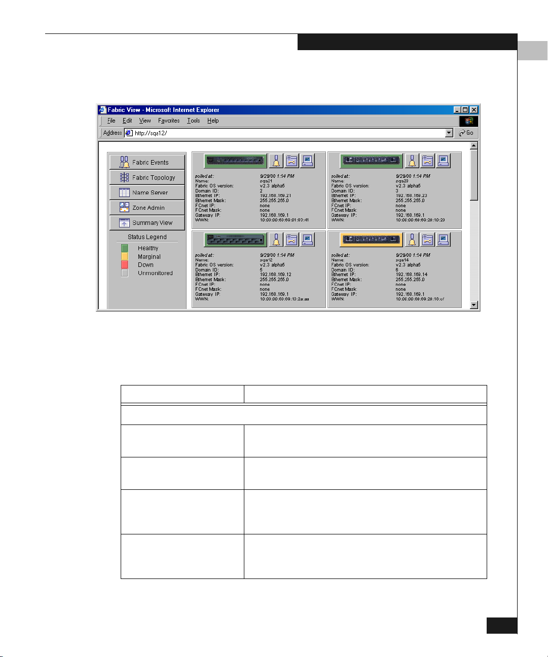
Web Tools launches, displaying Fabric View (Figure 3-1).
Figure 3-1 Fabric View
Using Web Tools
3
Table 3-1 describes the items visible in Fabric View.
Table 3-1 Fabric View Components
Component Description
The Control Panel (on the left side of Figure 3-1 on page 3-3)
Fabric Events Opens Fabric Events View (for information about
this view, see Fabric Events View on page 3-7).
Fabric Topology Opens Fabric Topology View (for information about
this view, see Fabric Topology View on page 3-9).
Name Server Opens Name Server Table View (for information
about this view, see Name Server Table View on
page 3-13).
Zone Admin Opens Zone Administration View (for information
about this view, see Zone Administration View on
page 3-16).
Fabric View
3-3
Page 30
Using Web Tools
3
Table 3-1 Fabric View Components (continued)
Component Description
Summary/Detail View Toggles the Summary or Detail version of Fabric
View. The Summary version shows abbreviated
switch panels (see Figure 3-2 on page 3-6). Detail is
the default view.
Status legend Defines meaning of colors visible in the background
of the switch icons. Each color indicates a different
operational state:
• Green — Healthy
• Yellow — Marginal (mix of good and faulty
readings)
• Red — Down (more than two faulty
readings)
• Gray — Unknown or unmonitored
If no data is available from a switch, Web Tools
displays the most recent background color.
3-4
For all statuses that are based on errors per time interval,
any errors will cause the status to show faulty until the
entire sample interval has passed.
The Switch Panel (on the right side of Figure 3-1 on page 3-3.)
Switch Opens Switch View for the switch. Each switch type
is represented by a different icon. The background
color around the icon indicates the status of the
switch (for information about this view, see Switch
View on page 3-29).
Events Opens Switch Events View to display the switch
events log (for information about this view, see
Switch Events View on page 3-33).
Admin Opens Switch Administration View (for information
about this view, see Administrative Interface on
page 4-2.
Te l ne t Launches the Telnet Interface for the switch (for
information about this view, see Telnet Interface on
page 4-23.
Departmental Switch Models DS-16B and DS-8B Web Tools User Guide
Page 31

Table 3-1 Fabric View Components (continued)
Component Description
Using Web Tools
3
polled at or unreachable
since
Time of the last status check, or if currently
unavailable, the time of the last successful status
check.
Name The name of the switch.
Fabric OS version Version of Fabric OS installed on the switch.
Domain ID A number that uniquely identifies the switch within
the fabric.
Ethernet IP Ethernet IP address.
Ethernet Mask Ethernet subnetmask.
FCnet IP Fibre channel IP address.
FCnet Mask Fibre channel subnetmask.
Gateway IP Gateway IP address.
WWN Unique numeric identifier for the switch; assigned
by manufacturer.
The Control Panel (on the left side of Figure 3-1 on page 3-3)
Fabric Events Opens Fabric Events View (for information about
this view, see Fabric Events View on page 3-7).
Fabric Topology Opens Fabric Topology View (for information about
this view, see Fabric Topology View on page 3-9).
Name Server Opens Name Server Table View (for information
about this view, see Name Server Table View on
page 3-13).
Figure 3-2 illustrates Fabric View with the Summary View selected.
Fabric View
3-5
Page 32

Using Web Tools
3
Figure 3-2 Summary Version — Fabric View
3-6
Departmental Switch Models DS-16B and DS-8B Web Tools User Guide
Page 33

Fabric Events View
Using Web Tools
3
The Fabric Events View provides a running log of events for all
switches in the fabric.
To access Fabric Events View:
1. Launch the web browser.
2. Enter the switch name or IP address in the Location/Address
field and press Enter. For example:
http://switch name/
Web Tools launches, displaying Fabric View (Figure 3-2).
3. Click Fabric Events. The Fabric Events View (Figure 3-3)
displays.
Figure 3-3 Fabric Events View
To sort the events by a particular column, click the column header.
To resize a column, drag the column divider.
Fabric Events View
3-7
Page 34

Using Web Tools
3
Table 3-2 describes the columns in the Fabric Events view.
Table 3-2 Fabric Events Columns
Column Description
Switch Displays the name of the switch
Num... (number) Displays the event number for an affected switch
Time Displays the time of an event
Count Displays the number of consecutive occurrences of same event
Level Displays the severity level of an event:
0—panic (switch reboots)
1—critical
2—Error
3—warning
4—information
5—debug
Message Describes the event
3-8
Departmental Switch Models DS-16B and DS-8B Web Tools User Guide
Page 35

Fabric Topology View
The Fabric Topology View summarizes the physical configuration of
the fabric from the perspective of the local domain (the domain of the
switch entered as a URL in the web browser). This includes
information about the destination domains (all other domains in the
fabric) and the paths between each destination domain and the local
domain.
To access Fabric Topology View:
1. Launch the web browser.
2. Enter the switch name or IP address in the Location/Address
3. Click Fabric Topology. The Fabric Topology View (Figure 3-4)
Using Web Tools
3
field and press Enter. For example:
http://switch name/
The switch entered into the web browser is identified by Web Tools as the
local domain.
Web Tools launches, displaying Fabric View (Figure 3-2).
displays.
Fabric Topology View
3-9
Page 36

Using Web Tools
3
3-10
Figure 3-4 Fabric Topology View
The window can be scrolled downwards to display information
(Figure 3-5) about the individual paths between the local switch
and each of the other switches in the fabric.
Departmental Switch Models DS-16B and DS-8B Web Tools User Guide
Page 37

Figure 3-5 Fabric Topology View, Scrolled Downwards
Using Web Tools
3
Table 3-3 describes the fields in the Fabric Topology View.
Table 3-3 Fabric Topology View
Field Description
View Fabric Topology
from Switch [switch name]
There are a total of [n]
Lists the switch in the domain that is assumed to be
the local domain.
The number of domains in the fabric.
domains in the fabric:
Local domain ID A number that uniquely identifies the local switch
within the fabric, and the name of the switch.
Domain ID (may be
more than one)
A number that uniquely identifies the switch within
the fabric, and the name of the switch.
Active Paths: This line is followed by information about each
destination domain, including information about each
of the paths between that domain and the local
domain.
Fabric Topology View
3-11
Page 38

Using Web Tools
3
Table 3-3 Fabric Topology View (continued)
Destination Domain IDThe ID of the destination domain that is described in
the lines following the ID. This information and the
two lines following it display for each destination
domain in the fabric.
Destination’s
The WWN of the destination domain.
Worldwide Name
Number of Paths The number of active paths between the destination
domain and the local domain.
Path Number The number assigned to the specific path described in
the table that follows this information. This
information and the following table display for each
path for which the domain described above is the
destination.
Output Ports The number of output ports on the path between the
destination domain and the local domain.
Input Ports The number of input ports on the path between the
destination domain and the local domain.
Hop Count The number of hops (interswitch links) between the
local domain and the destination domain.
Metric Metrics for traffic flow along the path.
Flag The flag assigned to the path.
3-12
Departmental Switch Models DS-16B and DS-8B Web Tools User Guide
Page 39

Name Server Table View
The Name Server Table View provides the name server entries listed
in the Simple Name Server database. This includes all name server
entries for the fabric, not only those that are local to the local domain.
Each row in the table represents a different device.
To access Name Server Table View:
1. Launch the web browser.
2. Enter the switch name or IP address in the Location/Address
field and press Enter.
http://switch name/
Web Tools launches, displaying Fabric View (Figure 3-2).
3. Click Name Server. The Name Server Table View (Figure 3-6)
displays.
Using Web Tools
3
Figure 3-6 Name Server Table View
Name Server Table View
3-13
Page 40

Using Web Tools
3
To sort the events by a particular column, click the column header. To
resize a column, drag the column divider.
The following fields are included in the Name Server Table View:
Table 3-4 Name Server Table View Fields
Field Description
Auto Refresh Enables Auto Refresh or uncheck to disable.
Auto Refresh Interval If Auto Refresh is checked, enters the number of seconds for the
refresh interval.
Refresh Refreshes the window display.
Done Closes the window.
The Name Server Table contains the following columns:
Table 3-5 Name Server Table View Columns
Column Description
3-14
Domain # The domain ID of the switch to which the device is connected.
Port # The number of the switch port to which the device is connected.
Port ID The port ID of the device (24-bit hexadecimal value).
Port Type The port type of the device (N for fabric direct attached port or
NL for fabric direct attached loop port).
Port WWN The worldwide name of the device port.
Node WWN The worldwide name of the device node.
Symbolic Name The symbolic name of the device assigned through the SCSI
INQUIRY command.
FC4 Types The fibre channel FC4 layer types supported by the device, such
as IP or FCP.
COS The fibre channel classes of service supported by the device.
Fabric Port Name The name of the fabric port in use by the device.
Departmental Switch Models DS-16B and DS-8B Web Tools User Guide
Page 41

Using Web Tools
Table 3-5 Name Server Table View Columns (continued)
Port IP Address The IP address of the fabric port.
Hard Address The hard address of the fabric port.
Member of Zones The zones to which this device belongs. This column does not
update when the table is refreshed. To view updated zoning
information, close and reopen the Name Server Table.
3
Name Server Table View
3-15
Page 42

Using Web Tools
3
Zone Administration View
Administrative privileges are required to access this view. If a switch
or device is added or removed from the network, it is necessary to
save the changes and relaunch the Zone Administration view for the
changes to take effect.
When administering Zoning, EMC recommends that you perform the
following steps:
1. Define a zone alias for each individual device to make zone
administration easier.
2. Create zones and add zone members.
3. Place zones into one or more zone configurations.
4. Enable one of the zone configurations (only one can be enabled at
a time).
There are three separate methods for adding members to a zone. Each
method corresponds to a zoning mode, and the combination of the
methods corresponds to an additional mode. Once you select a mode,
all zoning operations must correspond to that mode, and any zones,
aliases, and configuration files which do not cannot be selected.
3-16
EMC recommends the use of WWN Zoning. See Table 3-6 for more
information on this mode.
Table 3-6 Adding Members to a Zone
Zoning Mode Method Description
Port Level Zoning Zoning by physical domain/port number. All alias, zoning, and
configuration file operations must be performed using port.
Aliases, zones, and configuration files which have objects other
than ports cannot be selected or operated on.
WWN Level Zoning Zoning by WWNs only. All alias, zoning, and configuration file
operations must be performed by WWNs. Aliases, zones, and
configuration files that have objects other than WWNs cannot be
selected or operated on.
Departmental Switch Models DS-16B and DS-8B Web Tools User Guide
Page 43

Using Web Tools
Table 3-6 Adding Members to a Zone (continued)
Mixed Level Zoning Zoning by physical domain/port number or WWN. With mixed
level zoning, any object can be selected to be a member of a zone,
alias, or configuration file. This mode is supported for backward
compatibility with all 2000-series switches.
For more information about using Zoning, refer to the Departmental Switches
Model DS-16B and DS-8B Zoning User Guide.
To access the Zone Administration View:
1. Launch the web browser.
2. Enter the switch name or IP address in the Location/Address
field and press Enter. This switch is assumed to be the local
domain.
http://switch name/
Web Tools launches, displaying Fabric View (Figure 3-2).
3. Click Zone Admin.
3
The Zone Administration View displays (Figure 3-7).
For information specific to QuickLoop to be available, the QuickLoop
switch must be the local domain.
The following is a list of the tabs provided in the Zone Admin View,
and the pages on which they are described:
◆ Alias Tab on page 3-18
◆ Zone Tab on page 3-20
◆ QuickLoop Tab on page 3-22
◆ Fabric Assist Tab on page 3-24
◆ Config Tab on page 3-27
Zone Administration View
3-17
Page 44

Using Web Tools
3
Alias Tab
You use the Alias tab (Figure 3-7) to create and manage aliases for
devices in the fabric. An alias can have one or more members,
including switches, ports, WWNs, and QuickLoop AL_PAs.
3-18
Figure 3-7 Alias Tab — Zone Administration View
Table 3-7 describes the fields on the Alias tab.
Table 3-7 Alias Tab Fields
Field Description
Alias Name To modify an existing alias, select an alias name.
Create Alias Click to create a new alias. A dialog displays in which you can
enter the name of the new alias. All names must be unique and
contain no spaces or dash "-" characters.
Delete Alias Click to delete the alias selected in the Alias Name field. Deleting
an alias automatically removes it from all zones.
Departmental Switch Models DS-16B and DS-8B Web Tools User Guide
Page 45

Using Web Tools
Table 3-7 Alias Tab Fields (continued)
Rename Alias Renames the alias selected in the Alias Name field. A dialog
displays in which you can edit the alias name. Renaming an alias
automatically renames it in all zones.
3
Member
Selection List
Provides a list of potential alias members, including switches,
ports, WWNs, QuickLoop AL_PAs, and Fabric Assists.
Add Member Adds the item selected in the Member Selection List to the Alias
Members list. You can add individual ports or an entire switch. If
a switch is added, all ports on the switch are added. To add a
device WWN, select either a node WWN (folder icon) or port
WWN (blue circle icon) from the WWN sub-tree.
Remove Member Removes the selected member selected from the [Alias name]
Members list.
Add Other Adds a WWN, switch port, QuickLoop AL_PA, or Fabric Assist
that is not available in the Member Selection List.
Alias Members The member list of the alias selected in the Alias Name field. The
name of this list depends on the name of the selected alias. If no
alias is selected, the name displays as
null Members.
Apply Applies all changes made since the Zone Administration View
was opened, including changes made on other tabs in the view.
Changes cannot be cancelled once applied.
Cancel Cancels all changes made since changes were last applied, and to
exit the Zone Administration View. Changes cannot be cancelled
once they are applied.
Done Applies all changes made since the Zone Administration View
was opened and to exit the Zone Administration View.
Zone Administration View
3-19
Page 46

Using Web Tools
3
Zone Tab
You can use the Zone tab (Figure 3-8) to create and manage zones. A
zone can have one or multiple members, and can include switches,
ports, WWNs, aliases, and QuickLoop AL_PAs.
3-20
Figure 3-8 Zone Tab — Zone Administration View
Table 3-8 describes the fields on the Zone tab.
Table 3-8 Zone Tab Fields
Field Description
Zone Name Modifies an existing zone, select a zone name.
Create Zone Creates a new zone. A dialog displays in which you can
enter the name of the new zone. All names must be
unique and contain no spaces or dash "-" characters.
Departmental Switch Models DS-16B and DS-8B Web Tools User Guide
Page 47

Using Web Tools
Table 3-8 Zone Tab Fields (continued)
Delete Zone Deletes the zone selected in the Zone Name field.
Deleting a zone automatically removes it from all zone
configurations.
Rename Zone Renames the zone selected in the Zone Name field. A
dialog displays in which you can edit the name of the
zone.
3
Member Selection
List
A list of potential zone members, including switches,
ports, WWNs, aliases, QuickLoop AL_PAs, and Fabric
Assists.
Add Member Adds the member selected in the Member Selection List to
the Zone Members list. If an entire switch is selected, all
ports on the switch are added to the zone. You can also
select individual ports. To add a device WWN, select
either a node WWN (folder icon) or port WWN (blue
circle icon) from the WWNs subtree. To add an alias to the
zone, select it from the Aliases subtree (the alias must
already exist).
Remove Member Removes the selected member from the [Zone name]
Members list.
Add Other Adds a WWN, switch, port, or QuickLoop AL_PA that is
not listed in the Member Selection List.
[Zone name]
Members
The members of the zone selected in the Zone Name field.
The name of this list depends on the name of the selected
zone. If no zone is selected, the name displays as
Members
.
null
Apply Applies all changes made since the Zone Administration
View was opened, including changes made on other tabs
in the view. Changes cannot be cancelled once they are
applied.
Cancel Cancels all changes since the changes were last applied
and to exit Zone Administration. Changes cannot be
cancelled once they are applied.
Done Applies all changes made since the Zone Administration
View was opened and to exit the Zone Administration
View.
Zone Administration View
3-21
Page 48

Using Web Tools
3
QuickLoop Tab
You use the QuickLoop tab (Figure 3-9) to create and manage
QuickLoops if used in conjunction with Zoning. For information on
managing the QuickLoop feature separately, see Loop Tab on
page 3-43. Refer to Departmental Switch Models DS-16B and DS-8B
Zoning Reference Manual for more information on zoning
3-22
Figure 3-9 QuickLoop Tab — Zone Administration View
Table 3-9 describes the fields on the QuickLoop tab.
Table 3-9 QuickLoop Tab Fields
Field Description
QuickLoop Name Modifies an existing QuickLoop name.
Create Qloop Creates a new QuickLoop. A dialog displays in which
you can enter the name of the new QuickLoop. All names
must be unique and contain no spaces.
Departmental Switch Models DS-16B and DS-8B Web Tools User Guide
Page 49

Using Web Tools
Table 3-9 QuickLoop Tab Fields (continued)
Delete Qloop Deletes the QuickLoop selected in the QuickLoop Name
field. Deleting a QuickLoop automatically removes it
from all aliases, zones, and zone configurations,
including the associated AL_PAs.
Rename Qloop Edits the name of the QuickLoop selected in the
QuickLoop Name field. A dialog displays in which you
can edit the name of the QuickLoop.
Switch Selection List Lists the switches available to add to the QuickLoop.
Add Member Adds the selected switch in the Switch Selection List to
the QuickLoop Members list.
Remove Member Removes the selected member from the [QuickLoop
name] Members list.
3
[QuickLoop name]
Members
Lists the members of the QuickLoop currently selected in
the QuickLoop Name field. The name of this list depends
on the name of the selected QuickLoop. If no QuickLoop
is selected, the name displays as null Members.
Apply Applies all changes made since the Zone Administration
View was opened, including changes made on other tabs
in the view. Changes cannot be cancelled once they are
applied.
Cancel Cancels all changes since the changes were last applied
and to exit Zone Administration. Changes cannot be
cancelled once they are applied.
Done Applies all changes made since the Zone Administration
View was opened and to exit the Zone Administration
View.
Zone Administration View
3-23
Page 50

Using Web Tools
3
Fabric Assist Tab
You can use the Fabric Assist tab (Figure 3-10) to create and manage
Fabric Assists.
EMC does not currently support Fabric Assist.
3-24
Figure 3-10 Fabric Assist Tab — Zone Administration View
Table 3-10 describes the fields on the Fabric Assist tab.
Departmental Switch Models DS-16B and DS-8B Web Tools User Guide
Page 51

Table 3-1 0 Fabric Assist Tab Fields
Field Description
FA Name Modifies an existing Fabric Assist, select a
Create FA Creates a new Fabric Assist. A dialog
Delete FA Deletes the Fabric Assist selected in the FA
Rename FA Edits the name of the Fabric Assist selected in
Member Selection List Provides a list of members available to add to
Using Web Tools
3
Fabric Assist name.
displays in which you can enter the name of
the new Fabric Assist. All names must be
unique and contain no spaces.
Name field. Deleting a Fabric Assist
automatically removes it from all aliases,
zones, and zone configurations, including the
associated AL_PAs.
the FA Name field.
the Fabric Assist.
Add Host Adds the selected item as a host to the [Fabric
Assist name] Members list. Only a domain
port or a WWN can be added as a host.
Add Member Adds the member selected in the Member
Selection List to the [Fabric Assist name]
Members list.
Remove Member Removes the selected member from the
[Fabric Assist name] Members list.
Add Other Adds the member selected in the Member
Selection List to the [Fabric Assist name]
Members list. Click to add an unlisted
domain port or WWN.
Add Other Host Adds a host to the [Fabric Assist name]
Members list. Click to add an unlisted
domain port or WWN. Click to add an
unlisted domain port or WWN as a host.
Zone Administration View
3-25
Page 52

Using Web Tools
3
Table 3-1 0 Fabric Assist Tab Fields (continued)
[Fabric Assist name]
Members
Provides a list of the members that belong to
the Fabric Assist currently selected in the FA
Name field. The name of this list depends on
the name of the Fabric Assist selected. If no
Fabric Assist is selected, the name displays as
null Members.
Apply Applies all changes made since the Zone
Administration View was opened, including
changes made on other tabs in the view.
Changes cannot be cancelled once they are
applied.
Cancel Cancels all changes since the changes were
last applied and to exit Zone Administration.
Changes cannot be cancelled once they are
applied.
Done Applies all changes made since the Zone
Administration View was opened and to exit
the Zone Administration View.
3-26
Departmental Switch Models DS-16B and DS-8B Web Tools User Guide
Page 53

Using Web Tools
3
Config Tab
You use the Config tab (Figure 3-11) to create and manage zone
configurations. Zone configurations allow you to enable or disable a
group of zones simultaneously. Only one zone configuration can be
enabled on a fabric at one time.
Figure 3-11 Config Tab — Zone Administration View
Table 3-11 describes the fields on the Config tab.
Table 3-1 1 Config Tab Fields
Field Description
Config Name Modifies an existing configuration, select a configuration
name.
Create Cfg Creates a new configuration. A dialog displays in which
you can enter the name of the new configuration. All names
must be unique and contain no spaces or dash "-"
characters.
Zone Administration View
3-27
Page 54

Using Web Tools
3
Table 3-1 1 Config Tab Fields (continued)
Delete Cfg Deletes the configuration selected in the Config Name field.
Rename Cfg Renames of the configuration selected in the Config Name
field.
Zone/QLoop
Selection List
Provides a list of the zones and QuickLoops available to add
to the configuration.
Add Member Adds the switch selected in the Zone/QLoop Selection List
to the Configuration Members list.
Remove Member Removes the selected member from the [Configuration
name] Members list.
[Configuration
name] Members
The members of the configuration selected in the Config
Name field. The name of this list depends on the selection.
Only one configuration can be enabled at a time; if none are
enabled, zoning is not active in the fabric.
Enable Config Enables the configuration selected in the Config Name field,
or uncheck to disable it.
Config to enable Displays the name of the configuration that is currently
selected for enabling. This configuration can be enabled by
clicking Apply.
Config currently
enabled
Displays the name of the currently enabled configuration.
Only one configuration can be enabled at a time.
Apply Applies all changes made since the Zone Administration
View was opened, including changes made on other tabs in
the view. Changes cannot be cancelled once they are
applied.
3-28
Cancel Cancels all changes since they were last applied and to exit
the Zone Administration View. Changes cannot be
cancelled once applied.
Done Applies all changes made since the Zone Administration
View was opened and to exit the Zone Administration
View.
Departmental Switch Models DS-16B and DS-8B Web Tools User Guide
Page 55

Switch View
Using Web Tools
3
The Switch View represents the front panel of the switch, and
displays when you click a Switch icon in Fabric View. This view
provides information about the overall status of the switch and the
status of the individual elements in the switch. The information
displayed is as close as possible to a real-time view of switch status. If
the switch is not functioning properly, a message explains the
problem detected.
Switch status is stored as the variable switchStatus, and is calculated
approximately once per second; however the initial calculation does not
occur until 30-60 seconds after the switch is booted.
To access Switch View:
1. Launch the web browser.
2. Enter the switch name or IP address in the Location/Address
field and press Enter. For example:
http://switch name/
Web Tools launches, displaying Fabric View (Figure 3-2).
3. Click the Switch icon. The Switch View (Figure 3-12) displays.
Figure 3-12 Switch View
Switch View
3-29
Page 56
Using Web Tools
3
Table 3-12 describes the items and information available in Switch
View.
Table 3-1 2 Switch View
Port icons The letters in the Port icon indicate the GBIC (Gigabit Interface
Converter) type, as follows:
blank — No GBIC present.
SW — Short wave GBIC
LW — Long wave GBIC
CU — Copper GBIC
SWID — Short wave serial ID GBIC
LWID — Long wave serial ID GBIC
CUID — Copper serial ID GBIC
A yellow outline around a port icon indicates port failure. For detailed
port information, click the Port icon to see the Port Information View.
Port numbers
The number of the port.
(on the right of
each port)
LED Status
Indicators
(round light
next to each
port)
The color indicates the status of the port:
• No light — No device attached
• Steady yellow — Receiving light, but not online; check cable
connections
• Slowly flashing yellow — Disabled (diagnostics or portDisable
command).
• Rapidly flashing yellow— Error, fault with port
• Steady green — Online (connected with device by cable)
• Slowly flashing green — Online but segmented (loopback cable or
incompatible switch)
• Rapidly flashing green — Internal loopback (diagnostic)
• Flickering green — Online and transmitting/receiving frames
Power supply Removable power assemblies are updated to show presence/absence
and status of each:
• Green — Power supply present and operational.
• Red X — Power supply present but not operational.
• Cover plate — Power supply absent or not fully plugged in.
Events Accesses Switch Events View
3-30
Te l ne t Launches a Telnet session
Departmental Switch Models DS-16B and DS-8B Web Tools User Guide
Page 57

Table 3-1 2 Switch View (continued)
Using Web Tools
3
Fabric Watch
Accesses Fabric Watch
(optional
software)
Fan The background color of the button indicates the overall status of the
fans:
• Green — Healthy
• Ye ll o w — Marginal (mix of good and faulty readings)
• Red — Down (more than two faulty readings)
• Gray — Unknown or unmonitored
Admin Displays the Administrative Interface where you can perform switch
management functions.
Perf Displays the Performance View where you can monitor switch
performance.
Beacon Turns on the beaconing function. If on, this icon shows beams of light.
The beaconing function helps to physically locate a switch by sending a
signal to the specified switch, resulting in an LED light pattern flashing
from side to side on the switch.
Te mp Displays temperature readings from all switch thermo sensors. The
background color of the button indicates the overall temperature status:
• Green — Healthy
• Ye ll o w — Marginal (mix of good and faulty readings)
• Red — Down (more than two faulty readings)
• Gray — Unknown or unmonitored
WWN Displays the unique numeric identifier for each switch; assigned by
manufacturer.
Domain ID Displays the unique numeric identifier for each switch in a fabric.
Role Indicates the current role of the switch:
• Principal —The principal switch as defined by FC_SW protocol.
• Subordinate — Enabled but not the principal switch.
• Disabled — Disabled.
Switch View
3-31
Page 58

Using Web Tools
3
Table 3-1 2 Switch View (continued)
State Indicates the current state of the switch:
• online
• offline
• testing
• faulty
Firmware Fabric OS version.
Serial # The serial number of the switch being viewed.
Ether IP Ethernet IP address.
Ether NM Ethernet netmask value.
FC IP Fibre channel IP address.
FC NM Fibre channel netmask value.
Gateway IP address of default gateway. Must be properly set to access switch from
other networks.
3-32
Departmental Switch Models DS-16B and DS-8B Web Tools User Guide
Page 59

Switch Events View
Using Web Tools
3
The Switch Events View displays a running log of events for the
selected switch.
To access Switch Events View:
1. Launch the web browser.
2. Enter the switch name or IP address in the Location/Address
field and press Enter. For example:
http://switch name/
Web Tools launches, displaying Fabric View.
3. Click the Switch icon. The Switch View (Figure 3-12) displays.
4. Click the Events icon.
The Switch Events View (Figure 3-13) displays.
Figure 3-13 Switch Events View
To sort the events by a particular column, click the column header. To
resize a column, drag the column divider.
Switch Events View
3-33
Page 60

Using Web Tools
3
Table 3-13 lists available columns in Switch Events View.
Table 3-1 3 Switch Events
Field Description
Switch Name of switch
Num... Event number
Time Time of event
Count Number of back-to-back occurrences of same event
Level Severity level of event:
0 panic (switch reboots)
1 critical
2 error
3 warning
4 information
5 debug
Message Description of event
3-34
Departmental Switch Models DS-16B and DS-8B Web Tools User Guide
Page 61
Port Information View
The Port Information View displays statistics for the selected port.
This information is automatically updated when the view is opened,
and is also refreshed periodically while the view remains open.
To access Port Information View:
1. Launch the web browser.
2. Enter the switch name or IP address in the Location/Address
3. Click the Switch icon in Fabric View to display the Switch View.
4. Click a Port icon. The Port Information View (Figure 3-14)
Using Web Tools
3
field and press Enter. For example:
http://switch name/
Web Tools launches, displaying Fabric View (Figure 3-2).
displays.
Figure 3-14 Port Information View
Port Information View
3-35
Page 62

Using Web Tools
3
The following tabs are available in Port Information View and are
described on the listed pages:
◆ PortStats Tab on page 3-38
◆ GBIC Tab on page 3-40
◆ Loop Tab on page 3-43
Table 3-14 describes the fields that are always visible in Port
Information View whenever a tab is selected.
Table 3-1 4 Port Information Fields
Field Description
Port World Wide Name World Wide Name (WWN) of this port.
Port Module The GBIC type, as follows:
-- — No GBIC present
SW — Short wave GBIC
LW — Long wave GBIC
CU — Copper GBIC
SWID — Short wave serial ID GBIC
LWID — Long wave serial ID GBIC
CUID — Copper serial ID GBIC
3-36
Port Status The current status of the port:
No_Module — No GBIC module is in this
port.
No_Light — Module is not receiving light.
No_Sync — Module is receiving light but out
of sync.
In_Sync — Module is receiving light and in
sync.
Laser_Flt — Module signaling a laser fault
(defective GBIC).
Port_Flt — Port is marked faulty (defective
GBIC, cable, or device).
Diag_Flt — Port failed diagnostics.
Online — Port is up and running.
Lock_Ref — Port is locking to reference
signal. ( continued on next page)
Departmental Switch Models DS-16B and DS-8B Web Tools User Guide
Page 63

Table 3-1 4 Port Information Fields (continued)
Port Status (continued) Removing a cable from an E_Port temporarily
generates errors, causing the status to show as
faulty. The status returns to healthy when the
sample interval has passed (the default interval is
1 minute).
Port Type The type of port:
E_Port — Switch link port
G_Port — Generic port
U_Port — Universal port
F_Port — Fabric port
FL_Port — Fabric loop port
L_Por t— Loop port
Using Web Tools
3
Port Information View
3-37
Page 64

Using Web Tools
3
PortStats Tab
The PortStats tab provides information about transmission speed,
reception speed, and the volume of traffic through the selected port.
3-38
Figure 3-15 PortStats Tab — Port Information View
Table 3-15 describes the fields on the PortStats tab:
Table 3-1 5 PortStats Tab Fields
Field Number of ...
4-Byte Word Transmitted Four-byte words transmitted.
4-Byte Word Received Four-byte words received.
Frames Transmitted Frames transmitted.
Frames Received Frames received.
C2 Frames Received Class 2 frames received.
C3 Frames Received Class 3 frames received.
Link Control Frames Received Link control frames received.
Departmental Switch Models DS-16B and DS-8B Web Tools User Guide
Page 65

Using Web Tools
Table 3-1 5 PortStats Tab Fields (continued)
Mcast Frames Received Multicast frames received.
Mcast Time-outs Multicast timeouts.
Mcast Frames Transmitted Multicast frames transmitted.
Time R_RDY Priority Times R_RDY has priority over frames to be
sent.
Time BB_Credit Zero Times BB_Credit went to zero.
Encd Errs Inside Frames Encoding errors inside frames.
Frames with CRC Errs Frames with CRC errors.
Short Frames Frames shorter than minimum.
Long Frames Frames longer than maximum.
Bad End-of-Frames Frames with faulty end-of-frames.
Encd Errs Outside Frames Frames with encoding errors outside frames.
C3 Frames Discarded Class 3 frames discarded.
3
LIP Ins LIPs received.
LIP Outs Times loop initialized by FL_Port.
Last LIP Received Last LIP received: AL_PD, AL_PS.
Frames Rejected F_RJTs sent.
Frames Busied F_BSYs sent.
Link Failure Times NOS received/sent.
Loss of Sync Times loss of sync occurred.
Loss of Signal Times loss of signal occurred.
Port Information View
3-39
Page 66

Using Web Tools
3
GBIC Tab
The GBIC tab provides information about the GBIC (Gigabit Interface
Converter) installed in the selected port. The information displayed
depends on the type of GBIC installed:
Standard GBIC Module type (short wave, long wave,
copper, etc.).
Serial ID GBIC Module type, plus extended
information about capabilities,
interfaces, and manufacturer.
Smart Finisar GBIC All of the above information, plus
GBIC active status.
If the port does not contain a GBIC, the following information
displays:
Not a serial ID GBIC. No GBIC info available.
3-40
Figure 3-16 GBIC Tab — Port Information View
Table 3-16 describes the fields on the GBIC tab:
Departmental Switch Models DS-16B and DS-8B Web Tools User Guide
Page 67

Using Web Tools
Table 3-1 6 GBIC Tab Fields
Field Description
Identifier Indicates the type of serial transceiver, which can be GBIC or
on-board.
Connector Indicates the external connector type, which can be one of the
following:
SC
Style-1 Copper
Style-2 Copper
BNC/TNC
Coaxial
ID Name Indicates the GBIC module type:
-- — No GBIC present
sw — Short wave GBIC
lw — Long wave GBIC
c — Copper GBIC
swid — Short wave serial ID GBIC
lwid — Long wave serial ID GBIC
cuid — Copper serial ID GBIC
3
GBIC Speed Indicates the GBIC speed, which can be 100, 200, or 400 MB/sec.
GBIC Media Indicates the transmission media, which can be:
SM — single mode
M5 — multimode, 50u
M6 — multimode, 62.5u
TV — video coax
MI — miniature coax
TP — shielded twisted pair
TW — twin axial pair
GBIC Distance Indicates the length of the fibre channel link, which can be long
distance, intermediate distance, or short distance.
Encoding Indicates the serial encoding mechanism, which can be 8B10B,
4B5B, NRZ, or Manchester.
Baud Rate Nominal baud rate in units of 100 Megabyte.
BR Max Upper limit at which GBIC meets its specifications (in units of 1
percent above nominal baud rate).
Port Information View
3-41
Page 68

Using Web Tools
3
Table 3-1 6 GBIC Tab Fields (continued)
BR Min Lower limit at which GBIC meets its specifications (in units of 1
percent below nominal baud rate).
Options May indicate any of the following:
Loss of Signal
Loss of Signal Inverted
Transmission Fault
Transmission Disable
Length 9u Length of link using single mode fibre.
Length 50u Length of link using 50um multimode fibre.
Length 625u Length of link using 62.5um multimode fibre.
Length Cu Minimum length of link using copper cable.
Vendor Name Name of vendor.
Vendor OUI Unique identifier for vendor.
Vendor P/N Vendor part number.
3-42
Vendor Rev Vendor revision number.
Serial No. Ven dor ser ial number.
Date Code Vendor date code.
Smart GBIC Data (only displays if a smart GBIC is present):
Te mp e ra t ur e Module temperature (in Centigrade).
Rx Power Received optical power in micro Watts.
Tx Power Transmitted optical power in micro Watts (long wave only).
Current Laser diode drive current in mAmps.
Departmental Switch Models DS-16B and DS-8B Web Tools User Guide
Page 69

Using Web Tools
3
Loop Tab
The Loop tab (Figure 3-17) provides information about any loop on
the port, including the following:
◆ Loop statistics
◆ Local AL_PA statistics
◆ QuickLoop looplet statistics (if the port is a member of the
QuickLoop)
◆ QuickLoop statistics (if the port is a member of the QuickLoop)
If the port is not a loop-enabled port, the following information
displays:
Not an L_Port. No loop info available.
Figure 3-17 Loop Tab — Port Information View
Table 3-17 describes the fields on the Loop tab:
Table 3-1 7 Loop Fields
Field Displays the ...
FL Port Transfer Number of times FL_Port used transfer state.
FL Tenancies Number of times FL_Port opens loop tenancy.
Port Information View
3-43
Page 70

Using Web Tools
3
Table 3-1 7 Loop Fields (continued)
NL Tenancies Number of times NL_Port opens loop tenancy.
Number of QL/Zone Inits Caused Number of times looplet has caused
QuickLoop to be initialized.
Number of Successful QL/Zones Inits Number of times looplet has successfully
initialized.
Number of Failed QL/Zone Inits Number of times looplet failed to successfully
initialize.
Number of Times Being Bypassed Number of times looplet was not included as
part of QuickLoop.
Last Time bypassed Time that looplet was last bypassed.
Local AL_PA List List of AL_PAs associated with devices
connected to loop.
Number of QL Init Attempts Number of times QuickLoop attempted
initialization.
Number of Successful QL Inits Number of times QuickLoop successfully
initialized.
3-44
Number of Times in Single Switch Mode Number of times switch reverted to single
switch mode.
Number of Times in Dual Switch Mode Number of times switch operated in dual
switch mode.
Time of Last QL Init Time of latest QuickLoop initialization.
Switch, Port Caused the Last Init Displays number of switch, port that caused
the latest initialization.
Diag Loop Diagnostics dialog box, which enables
you to run loop diagnostics (requires
password). For more information, see Loop
Diagnostics Dialog Box on page 3-45.
Departmental Switch Models DS-16B and DS-8B Web Tools User Guide
Page 71

Using Web Tools
Table 3-1 7 Loop Fields (continued)
LIP LIP dialog box, which enables you to initialize
the loop (requires password). For more
information, see LIP Dialog Box on page 3-46.
Bypass Bypass dialog box, which enables you to
bypass a specified looplet (requires password).
For more information, see Bypass Dialog Box on
page 3-46.
Enable Enable dialog box, which enables you to enable
an AL_PA on a specified looplet (requires
password). For more information, see Enable
Dialog Box on page 3-47.
3
Loop Diagnostics
Dialog Box
Figure 3-18 Loop Diagnostics Dialog Box
This dialog box displays when you click DIAG on the Loop tab of the
Port Information View. You use the Loop Diagnostics option to
identify faulty devices on a loop.
Port Information View
3-45
Page 72

Using Web Tools
3
Table 3-18 describes the fields in the Loop Diagnostics dialog box
Table 3-1 8 Loop Diagnostics Fields
Field Description
Start Starts the Loop Diagnostics on the specified port.
Stop Stops (abort) Loop Diagnostics on the specified port.
Close Closes the Loop Diagnostics function.
LIP Dialog Box You can use the LIP (Loop Initialization Process) option to initialize a
loop port. To access this option, click LIP on the Loop tab of the Port
Information View.
Figure 3-19 LIP Dialog Box
3-46
Table 3-19 describes the fields in the LIP dialog box.
Table 3-1 9 LIP Fields
Field Description
Apply Initializes a loop port.
Close Closes the LIP dialog box.
Bypass Dialog Box You can use the Bypass option to bypass an AL_PA (a device) on the
loop port. To access this option, from Performance Information
View, click Bypass on the Loop tab.
Figure 3-20 Bypass Dialog Box
Departmental Switch Models DS-16B and DS-8B Web Tools User Guide
Page 73

Using Web Tools
Table 3-20 describes the fields in the Bypass dialog box.
Table 3-2 0 Bypass Fields
Field Description
AL_PA to Bypass Specifies the AL_PA number to bypass.
Do not bypass the last AL_PA on the loop, as this will put it
into a loopback state, requiring a reboot to return it to an
L-Port state.
Apply Bypasses an AL_PA on the loop port (must be a valid AL_PA).
Close Closes the Bypass dialog box.
Enable Dialog Box You can use the Enable option to enable an AL_PA on the loop port
that was previously bypassed. To access this option, from Port
Information View, click Enable on the Loop tab.
3
Figure 3-21 Enable Dialog Box
Table 3-21 describes the fields in the Enable dialog box.
Table 3-2 1 Enable Fields
Field Description
AL_PA to Enable Specifies AL_PA to be enabled. Entering oxff enables
all the AL_PAs in the loop.
Apply Enables the AL_PA (must be valid AL_PA).
Close Closes an AL_PA window.
Port Information View
3-47
Page 74

Using Web Tools
3
Fabric Watch View
You use Fabric Watch View to monitor fabric elements for potential
problem conditions. For detailed information about Fabric Watch, see
the Departmental Switch Model DS-16B Fabric Watch User Guide.
To access Fabric Watch View:
1. Launch the web browser.
2. Enter the switch name or IP address in the Location/Address
field and press Enter.
http://switch name/
Web Tools launches, displaying Fabric View.
3. Click the Switch icon.
The Switch View displays.
4. Click the Wa tch icon.
The Fabric Watch View displays, with the Alarm Notifications tab
(described in the following section) selected by default.
3-48
Fabric Watch View contains the following tabs:
• Alarm Notifications
• Configure Thresholds
• Current Settings
In addition, an organizational tree appears on the left, showing all the
Fabric Watch areas regardless of which tab is selected. To expand or
contract a folder in the tree, double-click the folder.
Departmental Switch Models DS-16B and DS-8B Web Tools User Guide
Page 75
Using Web Tools
3
Alarm Notifications Tab
You can use the Alarm Notifications tab (Figure 3-22) to view and
customize the Fabric Watch notifications. You can either accept the
default notifications or select the Custom option and specify the type
of notification (Syslog, SNMP_Trap, or Port log lock) for each type of
event.
Figure 3-22 Alarm Notifications Tab — Fabric Watch View
Fabric Watch View
3-49
Page 76

Using Web Tools
3
Configure Thresholds
You can use the Configure Thresholds tab to view and configure
Fabric Watch thresholds for the Fabric Watch class currently selected
in the organizational tree on the left side of the window.
3-50
Figure 3-23 Configure Threshold Tab with Environment Class Selected
Departmental Switch Models DS-16B and DS-8B Web Tools User Guide
Page 77

Using Web Tools
The Configure Threshold display changes according to the class and
area selected in the organizational tree. However, the Configure
Thresholds tab always contains the following buttons:
Default Returns settings to default values.
Apply Applies the values specified in the current display. When you
click Apply after a change, the Alarm Mechanism dialog box
displays:
To continue, select the type of alarm you want and click Apply.
Reset Restores the last changes that were applied.
3
Thresholds for the
Environmental and
The Environmental and GBIC classes both display a separate column
for each area (see
Figure 3-23).
GBIC Classes
Table 3-2 2 Environmental and GBIC Classes Thresholds
Threshold Description
The columns for the Te m p e r a t ur e , Fan, RX Power, and TX Power areas contain the following
items:
Threshold Type drop-down
list
Selects the threshold type (outranged, above, in-between,
below, changed).
High/Low drop-down list Selects to enter the high and low settings for the
threshold type selected in the Threshold Type drop-down
list (not available for all areas).
Scale Specifies the point at which you want to set the specified
threshold.
Area drop-down list Selects a Fabric Watch area.
Fabric Watch View
3-51
Page 78

Using Web Tools
3
Table 3-2 2 Environmental and GBIC Classes Thresholds (continued)
Watched checkbox Checks or unchecks to specify whether you want this area
watched (not available for all areas).
The column for the Power Supply and Current areas contain the following item:
“Send alarms when” box Specifies whether you want to be notified when the area
is in the acceptable range (OK) or is faulty (FAULTY).
Thresholds for the
Remaining Classes
Table 3-2 3 Additional Port Class Thresholds
Threshold Description
Low text box Enters the lowest number of occurrences that
High text box Enters the highest number of occurrences that
Threshold Type drop-down
list
Time period drop-down list Selects the time period you want applied to
The Port, E_Port, F/FL Copper Port, F/FL Optical Port classes
display the following fields for each area (Link Loss, Sync Loss,
Signal Loss, Protol Error, Invalid Words, Invalid CRCs, State
Changes, RX Performance, TX Performance):
are acceptable.
are acceptable.
Selects the type of threshold.
frequency measurements.
3-52
Departmental Switch Models DS-16B and DS-8B Web Tools User Guide
Page 79

Figure 3-24 displays the thresholds for the Port class.
Using Web Tools
3
Figure 3-24 Configure Threshold Tab with Port Class Selected
Fabric Watch View
3-53
Page 80

Using Web Tools
3
Current Settings Tab
The Current Settings tab (Figure 3-25) enables you to view the current
Fabric Watch threshold parameters for the area selected in the Fabric
Watch tree.
3-54
Figure 3-25 Current Settings Tab — Fabric Watch View
Departmental Switch Models DS-16B and DS-8B Web Tools User Guide
Page 81

Performance View
Using Web Tools
3
The Performance View graphically displays throughput (megabytes
per second) for each port and also for the entire switch.
◆ Port throughput is the number of bytes received at a port plus
the number of bytes transmitted.
◆ Switch throughput is the sum of the throughput for all the
ports.
To access Performance View:
1. Launch the web browser.
2. Enter the switch name or IP address in the Location/Address
field and press Enter. For example:
http://switch name/
Web Tools launches, displaying Fabric View (Figure 3-2).
3. Click the Switch icon. The Switch View (Figure 3-12) displays.
4. Click the Performance icon. The Performance View displays.
Figure 3-26 Performance View
Performance View
3-55
Page 82

Using Web Tools
3
In addition to the port graphs, a graph for the entire switch is
provided at the bottom of the window. Resizing the window changes
the size and shape of all the individual graphs.
In both the port and switch graphs, the horizontal axis represents
elapsed time and the vertical axis represents throughput. By default
the port graph contains approximately 10 minutes worth of data and
the switch graph contains approximately 20 minutes of data.
3-56
Departmental Switch Models DS-16B and DS-8B Web Tools User Guide
Page 83

Invisible Body Tag
4
Administrative
Interface
◆ Administrative Interface ...................................................................4-2
◆ Switch Administration ......................................................................4-4
◆ User Administration..........................................................................4-7
◆ SNMP Administration.....................................................................4-11
◆ License Administration...................................................................4-13
◆ Remote Switch ..................................................................................4-14
◆ QuickLoop Administration ............................................................4-16
◆ Config Admin Tab............................................................................4-18
◆ Extended Fabric Tab (Optional Software) ....................................4-21
◆ Telnet Interface .................................................................................4-23
Administrative Interface
4-1
Page 84

Administrative Interface
4
Administrative Interface
The Administrative Interface consists of the functions below. To
access the functions, from Switch View, click admin. The first
function to display is Switch Administration.
◆ Switch Administration
◆ User Administration
◆ Firmware Upgrade
◆ Reboot Switch
◆ SNMP Administration
◆ License Administration
◆ Remote Switch
◆ QuickLoop Administration
◆ Configuration Administration
◆ Extended Fabric
You access all other Administrative Interface functions by clicking the
appropriate tab from any function.
4-2
You must have administrative privileges to access these functions. Once an
administrative login is entered, administrative privileges remain available
until the web browser is exited.
To access the Administrative Interface:
1. Launch the web browser.
2. Enter the switch name or IP address in the Location/Address
field and press Enter. For example:
http://switch name/
Web Tools launches, displaying Fabric View.
3. Click the Admin icon on the switch panel.
The Enter Network Password dialog displays.
Departmental Switch Models DS-16B and DS-8B Web Tools User Guide
Page 85

Figure 4-1 Enter Network Password
4. Enter your user name and password. The logon account must
have administrative privileges.
5. Click OK.
The Administrative Interface displays, with the Switch Admin
tab selected by default.
The sections that follow describe each function detail.
Administrative Interface
4
Administrative Interface
4-3
Page 86

Administrative Interface
4
Switch Administration
Use Switch Administration to change IP information, disable a
switch, change the domain, change the switch name, or to see which
ports are disabled.
To access Switch Administration, click admin from the Switch View.
You can also click the Switch Admin tab from any Administration
function.
.
4-4
Figure 4-2 Switch Administration
Departmental Switch Models DS-16B and DS-8B Web Tools User Guide
Page 87

Administrative Interface
Table 4-1 describes the fields on the Switch Administration tab:
Table 4-1 Switch Administration Tab
Field Description
Switch Name Displays or sets the switch name. To change the switch name,
enter new name in this field.
Domain ID Displays or sets switch domain ID. Domain IDs must be unique
within a fabric. To change domain ID, enter new domain ID in
this field. Use a number from 1 to 239 for normal operating mode
(FCSW compatible) and a number from 0 to 31 for VC encoded
address format mode (backward compatible to 1000-series
switches).
Extended Fabric Allows ports to be configured for long distance, or uncheck to
turn the option off.
Switch Disabled Disables the switch, or uncheck to enable the switch.
Ethernet IP Displays or sets IP address for Ethernet connection to switch.
Ethernet Subnetmask Displays or sets Ethernet subnetmask. Default value is none.
Contact network administrator for value to enter. If changed,
restart browser.
4
Fibre Channel IP Displays or sets fibre channel IP address.
Fibre Channel Subnetmask Displays or sets fibre channel subnetmask. If changed, restart
browser.
Gateway IP Displays or sets gateway IP address. Contact network
administrator for IP address. If changed, restart browser.
Syslog Daemon IP Displays or sets destination station IP address for sending events
using syslog protocol to host. Contact network administrator for
IP address. If messages are not to be sent, enter none or leave
blank. Maximum of six IP addresses. Enter multiple addresses as
a list, for example
192.16864.35, 192.16862.36, etc.
Port No Returns the Port number.
Switch Administration
4-5
Page 88

Administrative Interface
4
Table 4-1 Switch Administration Tab (continued)
Port Disabled If the box is checked, disables the port.
Commit Configuration
Applies changes made.
Changes
Reset Resets all fields to values present when Switch Administration
was launched.
4-6
Departmental Switch Models DS-16B and DS-8B Web Tools User Guide
Page 89

User Administration
Administrative Interface
4
Use User Administration to rename accounts or change passwords.
To access User Administration, click the User Admin tab from any
Administration function.
Figure 4-3 User Administration
Table 4-2 describes the fields on the User Administration tab:
Table 4-2 User Administration Fields
Field Description
Access Level Access level required - Admin or User.
Change User Name To Enters new user name.
Change Password To Enters new password.
Verify Password Re-enter password to verify.
Commit User Name/Password Changes Applies changes made.
Reset Resets all fields to values set at last submission.
User Administration
4-7
Page 90

Administrative Interface
4
Firmware Upgrade Use Firmware Upgrade to download firmware upgrades.
To access Firmware Upgrade, click the Firmware Upgrade tab from
any Administration function.
Figure 4-4 Firmware Upgrade
Table 4-3 describes the fields on the Firmware Upgrade tab:
Table 4-3 Firmware Upgrade Tab
Field Description
Host Name or Host IP Displays or sets host name or host IP address.
Remote User Name Displays or sets remote user name.
Download File From Displays or sets absolute directory path from source host where
binary Fabric OS resides. (You must use forward slashes (
when downloading Fabric OS in a Windows environment. In
UNIX environment, path names cannot contain spaces, for
\temp\ds-16b\ver_220.)
4-8
example
Departmental Switch Models DS-16B and DS-8B Web Tools User Guide
/)
Page 91

Administrative Interface
Table 4-3 Firmware Upgrade Tab (continued)
Password Required for FTP Enters a password if FTP was selected as the protocol. The rsdh
daemon must be running if
Windows host, you must manually start the
rsh is selected. When running a
rshd.exe utility,
which is available from EMC Technical Support.
Download Firmware Downloads firmware.
Reset Resets all fields to values present when Firmware Upgrade was
launched.
4
Reboot Switch
Use Reboot Switch to reboot or fast boot the switch. POST (Power On
Self Test) can also be disabled for future reboots.
To access Reboot Switch, click the Reboot Switch tab from any
Administration function.
Figure 4-5 Reboot Switch
User Administration
4-9
Page 92

Administrative Interface
4
Table 4-4 describes the fields on the Reboot Switch tab:
Table 4-4 Reboot Switch Fields
Field Description
Disable POST Disables POST for future reboots; check it off to enable POST.
Commit Change Saves settings.
Reboot Switch Reboots the switch.
Fastboot Switch Performs a fast reboot. A fastboot bypasses POST. (This is the
same as a reboot with POST disabled.)
4-10
Departmental Switch Models DS-16B and DS-8B Web Tools User Guide
Page 93

SNMP Administration
Use SNMP Administration to set SNMP options.
To access SNMP Administration, click the SNMP Admin tab from
any Administration function.
Administrative Interface
4
Figure 4-6 SNMP Administration
SNMP Administration
4-11
Page 94

Administrative Interface
4
Table 4-5 describes the fields on the SNMP Administration tab:
Table 4-5 SNMP Administration Fields
Field Description
System Description Displays or sets system description. Default is Fibre
Channel Switch.
System Location Displays or sets location of switch. Default is End User
Premise.
System Contact Displays or sets contact information for switch. Default is
Field Support.
Event Trap Level Sets severity level of switch events that prompt SNMP
traps. Default is 0.
Enable
Authentication
Enables authentication traps; click off to disable
(recommended).
Tr a ps
Read Write
Community String
Read Only
Community String
Read Write and
Read Only Trap
Displays or sets up to three strings that work with the
SNMP
set command.
Displays or sets up to three strings that work with the
SNMP
get or get-next command.
Displays or sets recipients for traps (usually IP address of
SNMP management station).
Recipients
Commit SNMP
Applies changes made.
Changes
Reset Resets all fields to values present when SNMP
Administration was launched.
To disable the community string or trap recipient fields, leave them empty.
4-12
Departmental Switch Models DS-16B and DS-8B Web Tools User Guide
Page 95

License Administration
Use License Administration to add or remove licenses. This tab
displays a list of installed license keys and features. To access License
Administration, click the License Admin tab from any
Administration function.
All license keys are installed at the factory.
Administrative Interface
4
Figure 4-7 License Administration
License Administration
4-13
Page 96

Administrative Interface
4
Table 4-6 describes the fields on the License Administration tab:
Table 4-6 License Administration Fields
Field Description
License Key Enters license key to be added or removed.
Add License Adds a specified license.
Remove License Removes the specified license.
Removing a license could render a switch inoperable. Never
remove a license key unless instructed to do so by EMC
Technical Support.
Tex t Bo x A list of the licenses installed on the switch
Remote Switch
Use REMOTE SWITCH to configure a pair of switches to operate
over an extended WAN interface so that they can communicate across
an ATM network by using a CNT Fibre Channel to ATM interface.
This feature requires an active REMOTE SWITCH sublicense in both
switches.
4-14
Departmental Switch Models DS-16B and DS-8B Web Tools User Guide
Page 97

Administrative Interface
To access Remote Switch, click the Remote Switch tab from any
Administration function.
4
Figure 4-8 Remote Switch
Table 4-7 describes the fields on the Remote Switch tab:
Table 4-7 Remote Tab Fields
Tab Description
Remote Switch
Enabled
Commit Remote
Enables remote switch; check off to disable remote
switch.
Applies changes made.
Switch Change
Reset Resets all fields to values present when Remote Switch
was launched.
Remote Switch
4-15
Page 98

Administrative Interface
4
QuickLoop Administration
Use QuickLoop Administration to set up a QuickLoop for a single
switch or for a pair of switches. Select one or more switches, enable or
disable a QuickLoop at the switch level, and turn QuickLoop on or
off on an individual port.
For detailed information on QuickLoop, refer to the Departmental Switch
Models DS-16B and DS-8B QuickLoop Reference Manual.
To access QuickLoop Administration, click the QuickLoop Admin
tab from any Administration function.
4-16
Figure 4-9 QuickLoop Administration
Departmental Switch Models DS-16B and DS-8B Web Tools User Guide
Page 99

Table 4-8 describes the fields on the QuickLoop Administration tab:
Table 4-8 QuickLoop Administration Fields
Field Description
Administrative Interface
4
Enable Switch for
QuickLoop Mode
Enables switch for QuickLoop; check off to disable
switch for QuickLoop.
Port No Displays the port number.
QuickLoop Port
Enabled
QuickLoop Ports
Enables QuickLoop on port; check off to disable
QuickLoop on port.
If checked, indicates a port is currently bypassed.
Bypassed
Current QuickLoop
Partner
Select a QuickLoop
Partner for this
Switch
Displays the current partner switch WWN, domain ID,
and switch name of a dual-switch QuickLoop.
Selects a switch from the list of switch names currently
in the fabric as the partner switch of a dual-switch
QuickLoop.
Submit Applies changes made.
Reset Resets all fields to values present when QuickLoop
Administration was launched.
AL_PA Bitmap (in
hexadecimal)
Displays the AL_PA bitmap at the end of a QuickLoop
initialization.
Local AL_PAs Lists the AL_PAs of devices connected to the local
switch.
Remote AL_PAs Lists the AL_PAs of devices connected to the remote
switch if dual-switch QuickLoop is configured.
QuickLoop Administration
4-17
Page 100
Administrative Interface
4
Config Admin Tab
You can use the Config Admin tab to upload the switch configuration
file for archiving, or to download a new configuration file from the
host.
4-18
Figure 4-10 Config Admin Tab
Departmental Switch Models DS-16B and DS-8B Web Tools User Guide
 Loading...