

Page 1

EMC Departmental Switch
DS-24M2
Installation Guide
P/N 014003129
REV A01
October 22, 2002
This document explains the power, cooling, weight, and rack placement
requirements for the EMC DS-24M2 departmental switch. It also
describes the kits available for mounting the switch in EMC and
non-EMC racks and includes installation instructions as well.
Major sections are
• Power, Cooling, and Weight Information.............................................. 2
• Device Dimensions.................................................................................... 2
• Device Placement Requirements............................................................. 2
• Switch Mounting Kit Parts List ............................................................... 3
• Attaching Rail Mounting Hardware....................................................... 5
• Assembling the Rails................................................................................. 7
• Mounting the Slide Rails to the Switch................................................ 10
• Installing the Switch into the Cabinet ...................................................11
• Installing Latch Brackets or Ball Studs................................................. 13
1
Page 2

Power, Cooling, and Weight Information
Power, Cooling, and Weight Information
Device Power Requirements
DS-24M2 switch 90 to 264 Vac, 47 to 63 Hz 167 BTU/hr 17 lbs (7.7 kg)
Cooling Requirements
(Heat Dissipation) Maximum Weight
Device Dimensions
Device Height Depth Width
DS-24M2 switch 1.0 U 1.7 in 4.3 cm 19 in 48.3 cm 17.1 in 43.4 cm
Device Placement Requirements
There are no restrictions on the location of the DS-24M2 switch in the
rack/cabinet.
Switches are typically located at the top of the rack/cabinet in pairs.
Power distribution must support the number of outlets required for
the switch and the switch power rating listed in the table above.
2
EMC Departmental Switch DS-24M2 Installation Guide
Page 3
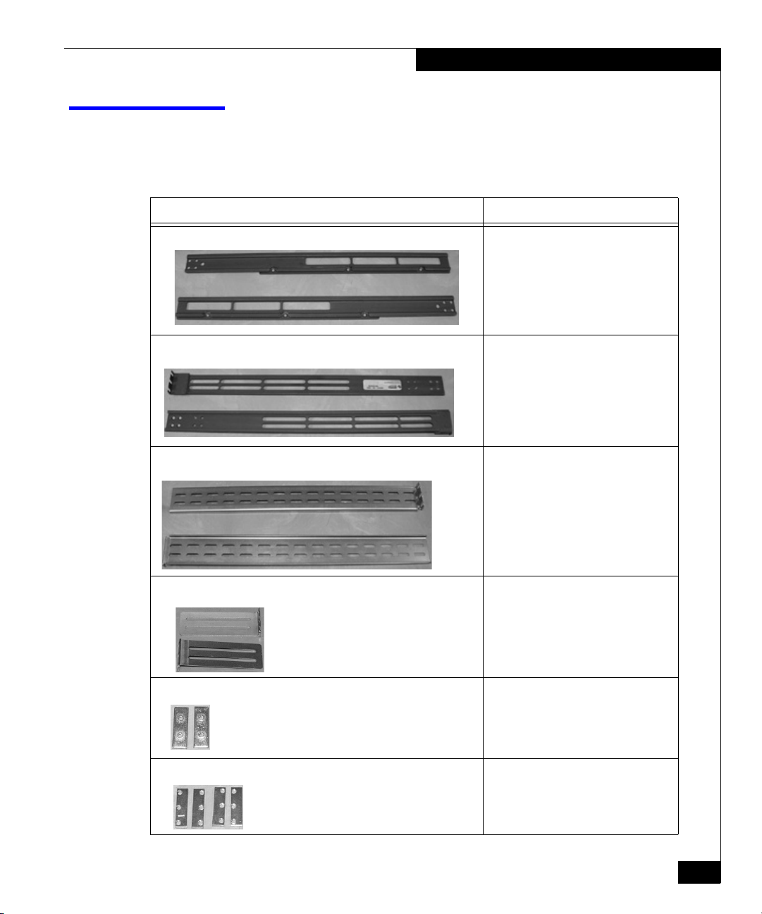
Switch Mounting Kit Parts List
The switch mounting kit includes rails, bezel, and power cords as
listed in the table below.
Component Use
2 mounting slide rails (left and right) 1 left and 1 right per switch
2 rear rails (left and right) 1 left and 1 right per switch
2 long front rails 2 per switch
Switch Mounting Kit Parts List
2 short rails 2 per switch
2-hole bar nuts 2 per switch for joining front and rear
rails
3-hole bar nuts 4 per switch for attaching the rails to the
front and rear channels
EMC Departmental Switch DS-24M2 Installation Guide
3
Page 4
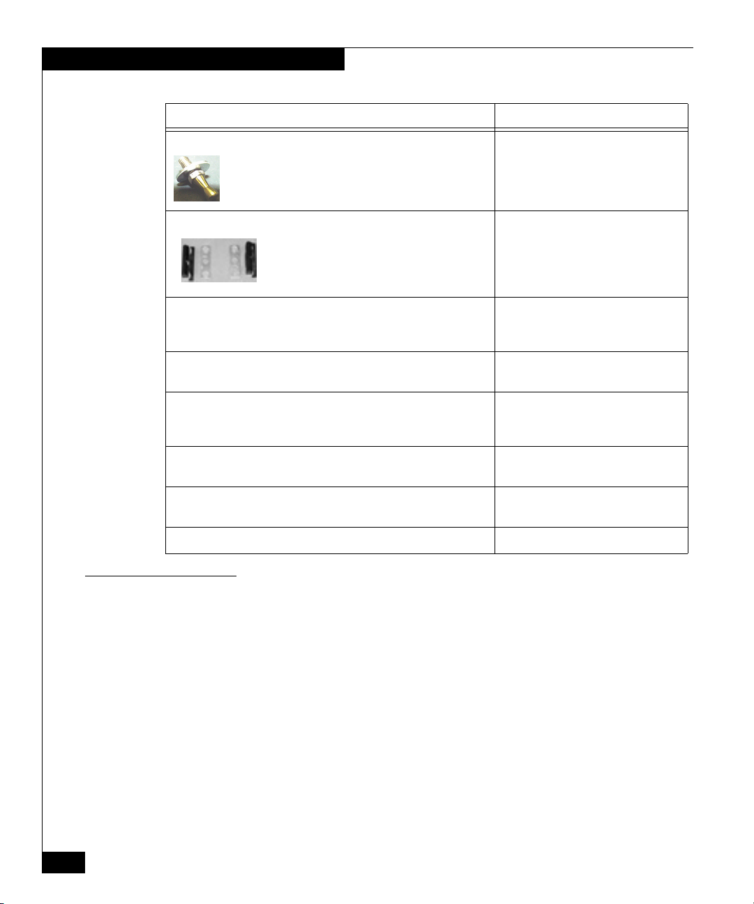
Switch Mounting Kit Parts List
Component Use
#10 washers ball studs 1 washer and 1 ball stud per rail to hold
bezel (2)
39U bezel only
Latch brackets and keyplate spacers 2 each to secure 1U bezel in 40U
cabinets
Ten (10) Phillips pan-head screws (#10 32x5/8) with split lock and flat
washers (SEMS)
Attaches the rail mounting hardware in
a 40U cabinet and a 39U cabinet
(round-hole channel only)
Four (4) Phillips flat-head screws (#8 32x3/8) Attaches the combined front and rear
rails.
Eight (8) Phillips flat-head screws (#10 32x5/8) and
Eight (8) square-hole washers
Attaches the rail mounting hardware in
a 39U cabinet (square-hole channel
only)
Four (4) Phillips flat-head securing screws (#8x32) Attaches the switch to the combined
front and rear rails.
A #10 Torx® screwdriver Removes and installs the Torx screws
on the switch.
1U low-profile or standard-profile bezel (front rack panel) 1 per switch
Tools Required for Installation
4
EMC Departmental Switch DS-24M2 Installation Guide
You will need the following tools to complete the installation of the
rails and switch(es). These tools are not available in this kit.
◆ # 2 Phillips head screwdriver
◆ A tape measure
Page 5
Attaching Rail Mounting Hardware
This section describes how to attach the rail mounting hardware to a
40U and 39U rackmount cabinet.
1. Determine the position of the switch in the cabinet. Each switch is
1.75 inches, or 1U, high.
There are no restrictions on the location of the switches in the
rack/cabinet. However, switches are typically located at the top of the
rack/cabinet in pairs.
2. If you are installing the switch in a 40U cabinet, do the following:
a. Mount two 3-hole nut bars on the inside of the front channel
so the nut bar holes are closest to the inside of the cabinet and
the keyplate spacer is on the outside of the front channels, as
illustrated in the figure below.
b. Insert the #10 32x5/8” screws in the top and bottom screw
holes. The center screw hole is used for the latch bracket (in a
40U cabinet) or the ball stud (in a 39U cabinet). Do not
completely tighten the nut bar screws at this time. You need to
leave the nut bar assembly loose enough to accommodate the
rail flange when you install the combined front and rear rails
later.
Attaching Rail Mounting Hardware
The keyplate spacer is marked such that an L or an R will be upright
when correctly installed on the left or right channel.
3-Hole Nut Bar
Keyplate Spacer
Front Rackmount Cabinet
EMC Departmental Switch DS-24M2 Installation Guide
5
Page 6

Attaching Rail Mounting Hardware
c. Mount two 3-hole nut bars on the inside of the rear channels
so the nut bar holes are closest to the inside of the cabinet, as
illustrated in the figure below.
d. Insert the #10 32x5/8” screws in the top and bottom screw
holes. Again, you need to leave the nut bar assembly loose
enough to accommodate the rail flange when you install the
combined front and rear rails later.
The keyplate spacer is not installed on the rear of the rackmount
cabinet.
Bar Nut
Rear Rackmount Cabinet
If you are installing the switch in a 39U cabinet, follow the steps for
the 40U cabinet but do not install the keyplate spacer. If your
cabinet has square-hole channels, you need to use the square-hole
washer and the #10 32x5/8” flat-head screws to attach the front
and rear mounting hardware.
6
EMC Departmental Switch DS-24M2 Installation Guide
Page 7

Assembling the Rails
This section describes how to assemble the rails for your rackmount
cabinet. Your rail kit contains two different-length front rail mounts
(for an illustration, see page 2); be sure to use the rail length that is
appropriate for your rack/cabinet.
If you want the optic connections in the front and the power connections in
the back, reverse the placement of the front and rear rails in the instructions
below. However, if you do this, you will not be able to get the bezel on the
cabinet.
1. Measure the depth of the cabinet from the inside of the front rail
2. Depending upon the depth of the cabinet, assemble one front rail
Assembling the Rails
to the inside of the rear rail.
(short or long) and one rear rail together so that the combined
rails (outside edge to outside edge) are equal to the depth of the
cabinet.
Do not use a front (long) rail and a rear rail together if the depth is under
22 inches as this could restrict air flow around the switch.
3. Using two #8 32x3/8” flat-head screws, attach one 2-hole nut bar
to hold the front and rear rails together. See the figure below.
Do not completely tighten the nut bars screws to the rails but tighten
them enough to hold the rails together.
2-Hole Bar Nut
Combined Front
and Rear Rails
Attaching Front and Rear Rails
EMC Departmental Switch DS-24M2 Installation Guide
7
Page 8

Assembling the Rails
4. Align the holes of the front rail flange to the inside of the front
and rear channel, as illustrated in the figure below. The rail
flanges go to the inside of the channels.
Nut Bar Screws
Flange to the Inside of the Front Channel
(Between the Channel and the Nut Bar).
Aligning Front Rail Flange
5. Verify that the length is correct and then tighten the #8 32x3/8”
nut bar screws so the front and rear rails are secure enough to
hold the switch; see the figure above. Do not completely tighten
the nut bar screws. You will tighten them once you install the
switch.
8
EMC Departmental Switch DS-24M2 Installation Guide
Page 9

Assembling the Rails
6. Secure the rail to the channel by hand tightening the #10 32x5/8”
pan-head (round-hole channel) or flat-head (square-hole channel)
screws on the outside of the front and rear channels. You will
tighten the screws after the switch is installed. See the figure
below.
DS-24M2 Round-Hole
Channel, Rear of Rack
(For Example, the
CLARiiON Rack/Cabinet)
DS-24M2 Square-Hole
Channel, Rear of Rack
(T
hird-Party Rack/Cabinet)
7. Repeat steps 3 to 6 for the other rail.
8. You are now ready to install the left and right slide rails onto the
DS-24M2 switch.
EMC Departmental Switch DS-24M2 Installation Guide
9
Page 10

Mounting the Slide Rails to the Switch
Mounting the Slide Rails to the Switch
This section describes how to mount the slide rail to the switch.
1. Locate the left and right slide rails shipped with the kit. See
Switch Mounting Kit Parts List on page 3.
2. On the left and right side of the switch, use the Torx screwdriver
shipped with the rail kit to remove the six Torx screws (three
screws per side) that help hold the switch cover in place. (You
will be attaching the slide rails using these screws, so do not
discard them.)
3. Attach the left and right slide rails to the switch with the six Torx
screws you removed earlier as shown in the figure below. Be sure
to match up the vent cutouts on the sliding rail to the vents on the
switch and that the securing screw holes are on the same side as
the switches power supply.
10
Attaching Slide Rails to DS-24M2 Switch
EMC Departmental Switch DS-24M2 Installation Guide
Page 11

Installing the Switch into the Cabinet
This section describes how to install the switch into the rackmount
cabinet.
1. Slide the switch into the mounting rails in the cabinet.
You can install the switch in the front or rear of the cabinet; however, it is
usually easier to install it from the rear.
2. Tighten the #8 32x3/8” nut bar screws that hold the front and rear
rails together, as illustrated in the figure below.
Installing the Switch into the Cabinet
Tightening Rail Nut Bar Screws
Nut Bar Screws
EMC Departmental Switch DS-24M2 Installation Guide
11
Page 12

Installing the Switch into the Cabinet
3. Install the #8x32” flat-head securing screws to prevent the switch
from moving, as illustrated in the figure below. You will install
only four screws (two on each side); two of the holes will be left
empty. (If you need to move the switch, you will need to remove
these screws.)
Securing
Screw
Installing Securing Screws
12
Make sure the screws do not cause the front rail to budge or bow. If the
screws cause the rail to budge or bow, then move the screws to the other
slot.
4. If you removed the power supplies, install the power supplies
you removed earlier. Before installing the power supplies, review
the Installation and Service Manual for instructions on installing
the power supplies.
5. Tighten the #10 32x5/8” pan-head (round-hole channel) or
flat-head (square-hole channel) screws on the outside of the front
and rear channels.
EMC Departmental Switch DS-24M2 Installation Guide
Page 13

Installing Latch Brackets or Ball Studs
This section describes how to install latch brackets (for a 40U cabinet)
or ball studs (for a 39U cabinet). Latch brackets and ball studs
support the bezel.
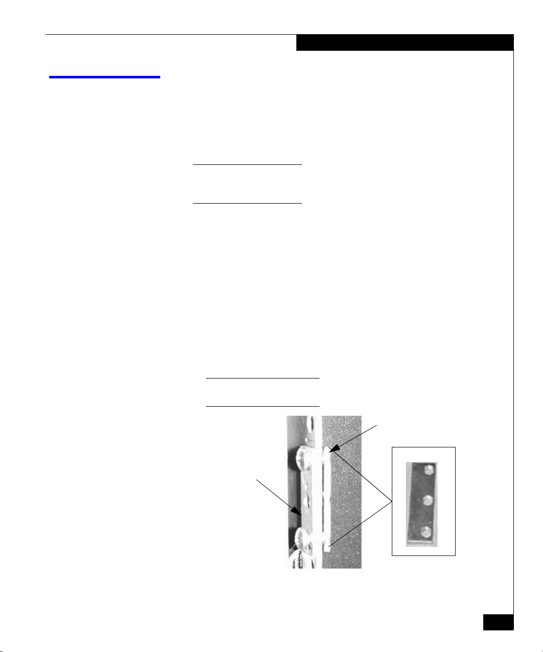
1. If you are installing the switch in a 40U cabinet, install the latch
bracket in the center hole, over the keyplate spacer, using a #10
32x5/8” pan-head screw. See the figure below.
Keyplate
Latch
Bracket
Screw
If you are installing the switch in a 39U cabinet (either in a round-hole
or square-hole channel), position the #10 washer and ball stud in the
center hole, between the two #10 32x5/8” flat-head screws.
Tighten the ball stud. See the figure below.
Spacer
Installing Latch Brackets or Ball Studs
EMC2488
#10 Flat
Ball
Washer
Stud
EMC2491
2. Repeat step 1 with the other side of the channel.
3. Attach the bezel to the front of the cabinet by lining the bezel up
with the latch brackets (40U) or ballstuds (39U) until the bezel
snaps into place.
EMC Departmental Switch DS-24M2 Installation Guide
13
Page 14

Installing Latch Brackets or Ball Studs
Copyright © 2002 EMC Corporation. All Rights Reserved.
EMC believes the information in this publication is accurate as of its publication date. The information is subject to
change without notice.
THE INFORMATION IN THIS PUBLICATION IS PROVIDED "AS IS." EMC CORPORATION MAKES NO
REPRESENTATIONS OR WARRANTIES OF ANY KIND WITH RESPECT TO THE INFORMATION IN THIS
PUBLICATION, AND SPECIFICALLY DISCLAIMS IMPLIED WARRANTIES OF MERCHANTABILITY OR
FITNESS FOR A PARTICULAR PURPOSE.
Use, copying, and distribution of any EMC software described in this publication requires an applicable software
license.
Trademark Information
EMC2, EMC, CLARiiON, and Navisphere are registered trademarks and Access Logix, SnapView and MirrorView are trademarks of EMC Corporation.
All other trademarks mentioned herein are the property of their respective owners.
14
EMC Departmental Switch DS-24M2 Installation Guide
 Loading...