

Page 1

EMC® Disk Library
DL3D 1500 and DL3D 3000
Version 1.1
ADMINISTRATOR’S GUIDE
P/N 300-006-695
REV A02
EMC Corporation
Corporate Headquarters:
Hopkinton, MA 01748
1
-508-435-1000
www.EMC.com
-9103
Page 2

Copyright © 2008-2009 EMC Corporation. All rights reserved.
Published February, 2009
EMC believes the information in this publication is accurate as of its publication date. The information is
subject to change without notice.
THE INFORMATION IN THIS PUBLICATION IS PROVIDED "AS IS." EMC CORPORATION MAKES NO
REPRESENTATIONS OR WARRANTIES OF ANY KIND WITH RESPECT TO THE INFORMATION IN THIS
PUBLICATION, AND SPECIFICALLY DISCLAIMS IMPLIED WARRANTIES OF MERCHANTABILITY OR
FITNESS FOR A PARTICULAR PURPOSE.
Use, copying, and distribution of any EMC software described in this publication requires an applicable
software license.
For the most up-to-date regulatory document for your product line, go to the Technical Documentation and
Advisories section on EMC Powerlink.
For the most up-to-date listing of EMC product names, see EMC Corporation Trademarks on EMC.com.
All other trademarks used herein are the property of their respective owners.
2
EMC DL3D 1500 andDL3D 3000 Administrator’s Guide
Page 3

Preface
Chapter 1 About the DL3D 1500/3000
Introduction to the DL3D 1500/3000............................................. 20
Advanced data de-duplication increases disk retention for
backup data .................................................................................20
Remote replication of backup data provides automated
disaster recovery protection......................................................20
Enterprise features provide secure, centralized repository..20
Data reduction................................................................................... 21
Data de-duplication....................................................................21
Hardware compression..............................................................22
Remote replication............................................................................ 23
Hardware components..................................................................... 24
DL3D 1500 components.............................................................24
DL3D 3000 components.............................................................24
Powering up the appliance.............................................................. 25
Powering up the storage system ..............................................25
Powering up the DL3D server..................................................25
Powering down the appliance ........................................................ 26
Powering down the DL3D server.............................................26
Powering down the storage system.........................................26
Contents
Chapter 2 DL3D 1500 and DL3D 3000 Remote Management
DL3D 1500 and DL3D 3000 web pages.......................................... 28
Supported browser software.....................................................28
Accessing DL3D 1500 and DL3D 3000 web pages.................28
EMC DL3D 1500 and DL3D 3000 Administrator’s Guide
3
Page 4

Contents
Chapter 3 Configuring DL3D 1500/3000
Accessing the configuration page .................................................. 36
Configuring the network ................................................................ 37
Viewing/editing the network configuration..........................37
Configuring the date and time ....................................................... 39
Date and time configuration.....................................................39
Configuring security ........................................................................ 41
Passwords....................................................................................41
SSL ................................................................................................ 43
Login session...............................................................................44
Configuring email............................................................................. 45
Recipients..................................................................................... 45
Server............................................................................................ 47
Test................................................................................................47
Configuring SNMP........................................................................... 48
Destinations.................................................................................48
Community .................................................................................49
Test................................................................................................51
Adding contacts information.......................................................... 52
Company .....................................................................................52
Primary/Secondary ...................................................................53
Chapter 4 Configuring and Managing Virtual Tape Libraries
Introduction....................................................................................... 56
Connecting the DL3D to the SAN............................................56
Virtual tape libraries.................................................................. 56
Other considerations.................................................................. 57
Configuring virtual tape libraries .................................................. 59
Accessing virtual tape libraries ...............................................59
Creating a virtual tape library ..................................................60
Creating media........................................................................... 62
Managing SAN clients...............................................................64
Managing targets........................................................................65
Viewing target usage .................................................................65
Adding a SAN client group ......................................................66
Single library with multiple hosts............................................67
Managing virtual tape libraries...................................................... 68
Editing a virtual tape library ....................................................68
Viewing virtual tape libraries...................................................69
Deleting a virtual tape library ..................................................69
Managing virtual tape library actions..................................... 70
Managing media actions ...........................................................72
4
EMC DL3D 1500 and DL3D 3000 Administrator’s Guide
Page 5

Managing SAN client groups....................................................74
Configuring and managing the Path-to-Tape feature.................. 76
Setting up the Path-to-Tape function.......................................76
Configuring the Path-to-Tape function ...................................77
Discovering physical devices ....................................................77
Configuring backup application-specific users......................79
Managing backup application specific user............................80
Configuring Auto Archive............................................................... 82
Claiming media.......................................................................... 82
Setting import/export behavior of media...............................84
Configuring early tape creation................................................85
Configuring barcode filters .......................................................86
Managing auto archive..................................................................... 87
Viewing media summary ..........................................................87
Managing virtual actions on the media...................................87
Managing cartridge access.........................................................89
Managing physical actions on the media................................90
Managing pending actions ........................................................91
Managing device modes ............................................................92
Chapter 5 Configuring and Managing Disk Backup
Configuring and managing disk backup....................................... 96
Configuring and managing NAS shares........................................ 97
Configuring NAS shares............................................................97
Managing NAS shares..............................................................106
Advanced Setting......................................................................108
Configuring and managing OST................................................... 109
Configuring OST.......................................................................109
Managing OST...........................................................................113
Contents
Chapter 6 Viewing Status
Accessing status............................................................................... 118
Hardware.......................................................................................... 118
Summary................................................................................... 119
Details ........................................................................................ 119
System............................................................................................... 122
CPU.............................................................................................122
Ethernet ......................................................................................122
De-duplication...........................................................................123
Ingest...........................................................................................123
Disk Usage .................................................................................124
EMC DL3D 1500 and DL3D 3000 Administrator’s Guide
5
Page 6

Contents
Fibre Channel............................................................................ 126
VTL ................................................................................................... 127
Physical view............................................................................. 127
Logical view ..............................................................................127
Performance view..................................................................... 128
Chapter 7 Managing Alerts
Alerts ................................................................................................ 130
Admin Alerts............................................................................ 130
Action Required........................................................................131
Service Tickets...........................................................................131
Chapter 8 Managing Data Services
Accessing data services.................................................................. 138
Space reclamation.....................................................................138
Space Reclamation page ..........................................................139
Configuring and implementing data replication....................... 141
Overview of the replication process......................................141
Configuring and managing data replication........................ 142
Prerequisites for replication....................................................143
Setting up the target DL3D appliance...................................144
Setting up the source DL3D appliance..................................146
Replicating to a target system.................................................149
Viewing replication status.......................................................155
Performing source role actions...............................................158
Performing target role actions................................................160
Recovering replicated data............................................................ 161
Data recovery ............................................................................161
Data failback..............................................................................163
Chapter 9 Managing Utilities
Accessing utilities ........................................................................... 166
Firmware....................................................................................166
Analyzer.....................................................................................167
Diagnostics ............................................................................... 168
Node management...................................................................171
License keys...............................................................................172
Chapter 10 Command Line Interface
Access to Command Line Interface ............................................. 174
6
EMC DL3D 1500 and DL3D 3000 Administrator’s Guide
Page 7

Contents
Command Line Interface syntax conventions......................174
Virtual tape library commands ..................................................... 176
list vtl ..........................................................................................176
list library ...................................................................................176
list tapedrive ..............................................................................177
add vtl.........................................................................................177
edit vtl.........................................................................................178
del vtl ..........................................................................................178
list mediatype ............................................................................178
add media...................................................................................179
list media....................................................................................179
del media....................................................................................180
export media..............................................................................180
recycle media.............................................................................181
writeprot media.........................................................................181
offline | online...........................................................................181
list host........................................................................................182
add host......................................................................................182
edit host......................................................................................182
del host .......................................................................................183
list target.....................................................................................183
list device....................................................................................183
list sanclientgroup.....................................................................184
add sanclientgroup...................................................................185
del sanclientgroup ....................................................................185
NAS commands............................................................................... 186
list share......................................................................................186
add share....................................................................................187
del share .....................................................................................187
join workgroup..........................................................................188
join ads........................................................................................188
disjoin workgroup ....................................................................188
disjoin ads ..................................................................................189
list user........................................................................................189
add user......................................................................................189
add user......................................................................................190
del user .......................................................................................190
getstatus nfs|cifs.......................................................................190
deleteall share............................................................................190
edit share....................................................................................191
deleteall user..............................................................................191
edit user......................................................................................191
add shareadmin.........................................................................191
EMC DL3D 1500 and DL3D 3000 Administrator’s Guide
7
Page 8

Contents
list shareadmin..........................................................................192
del shareadmin ......................................................................... 192
deleteall shareadmin................................................................192
add shareuser............................................................................192
list shareuser.............................................................................. 193
del shareuser .............................................................................193
deleteall shareuser....................................................................193
add sharehost............................................................................ 193
list sharehost..............................................................................194
del sharehost .............................................................................194
deleteall sharehost.................................................................... 194
get smbsetting...........................................................................194
set smbsetting............................................................................195
Status commands............................................................................ 196
get capacity................................................................................196
get capacity free........................................................................196
get capacity free dedup............................................................196
get capacity used ......................................................................196
get capacity used dedup.......................................................... 197
get ddratio .................................................................................197
Replication commands................................................................... 198
replicate vtl................................................................................ 198
replicate nas...............................................................................198
lock vtl........................................................................................198
lock nas.......................................................................................199
unlock vtl ...................................................................................199
unlock nas..................................................................................199
getstatus vtllock........................................................................199
getstatus naslock.......................................................................200
sync vtl .......................................................................................200
sync nas......................................................................................200
genrpt replication ..................................................................... 200
getstatus trigger........................................................................200
getstatus sync............................................................................201
OST commands............................................................................... 202
add storageserver .....................................................................202
del storageserver.......................................................................202
edit storageserver .....................................................................202
list storageserver....................................................................... 203
add lsu........................................................................................203
del lsu .........................................................................................203
edit lsu........................................................................................204
list lsu .........................................................................................204
8
EMC DL3D 1500 and DL3D 3000 Administrator’s Guide
Page 9

Appendix A DL3D Event Codes
Appendix B Veritas NetBackup OST and LSU Configuration
Veritas NetBackup OST and LSU Configuration........................ 218
Enabling Verbose Logging............................................................. 219
Appendix C Mounting or Mapping the NAS Shares
Mounting NFS shares..................................................................... 222
Mapping CIFS shares...................................................................... 225
Glossary
Index
Contents
EMC DL3D 1500 and DL3D 3000 Administrator’s Guide
9
Page 10

Contents
10
EMC DL3D 1500 and DL3D 3000 Administrator’s Guide
Page 11

Tables
1 Optional network node fields........................................................................ 38
2 SNMP trap selections...................................................................................... 48
3 Company information .................................................................................... 52
4 Primary/secondary contact information..................................................... 53
5 Summary Information .................................................................................... 73
6 Virtual actions.................................................................................................. 74
7 Workgroup users fields................................................................................ 103
8 Add NAS share fields................................................................................... 106
9 NAS Share Summary fields ......................................................................... 107
10 Storage Server Fields .................................................................................... 112
11 LSU fields ....................................................................................................... 113
12 Administration alerts.................................................................................... 130
13 System status.................................................................................................. 132
14 Server events.................................................................................................. 206
15 Server software events.................................................................................. 209
16 RAID events................................................................................................... 212
17 Fibre Channel HBA events .......................................................................... 213
18 Compression HBA events............................................................................ 214
19 Network data management protocol events............................................. 214
20 Software events.............................................................................................. 215
21 RAS events ..................................................................................................... 216
EMC DL3D 1500 and DL3D 3000 Administrator’s Guide
11
Page 12

Tables
12
EMC DL3D 1500 and DL3D 3000 Administrator’s Guide
Page 13

Preface
As part of an effort to improve and enhance the performance and capabilities
of its product line, EMC from time to time releases revisions of its hardware
and software. Therefore, some functions described in this document may not
be supported by all revisions of the software or hardware currently in use.
For the most up-to-date information on product features, refer to your
product release notes.
If a product does not function properly or does not function as described in
this document, please contact your EMC representative.
This manual introduces the EMC
protection systems and discusses:
®
DL3D 1500/3000 enhanced data
◆ System operations
◆ Configuration
◆ Web interface
Audience This manual is written for DL3D 1500/3000 system administrators
and field service engineers.
Note: You should have a basic understanding of UNIX® and
backup/recovery systems.
EMC DL3D 1500 and DL3D 3000 Administrator’s Guide
13
Page 14

Preface
Organization Following is a brief description of chapter contents.
Chapter 1 Provides an overview of the DL3D 1500/3000
system and procedures to power up and power
down the appliance.
Chapter 2 Describes how to use the DL3D 1500/3000 system
management pages to control the system remotely.
Chapter 3 Describes the DL3D 1500/3000 appliance
configuration.
Chapter 4 Describes the DL3D 1500/3000 virtual tape libraries
configuration.
Chapter 5 Describes the DL3D 1500/3000 backup
configuration - NAS configuration and OST
configuration.
Chapter 6 Contains a description of DL3D 1500/3000 status
information.
Chapter 7 Discusses the DL3D 1500/3000 alert information
such as email account configuration and SNMP
configuration.
14
Chapter 8 Describes the DL3D 1500/3000 data services such
as space reclamation and remote replication.
Chapter 9 Describes the DL3D 1500/3000 utilities, such as
VTL state, and rebooting the system.
Chapter 10 Describes the commands used in the Command
Line Interface of DL3D 1500/3000.
Appendix A Lists the event changes associated with the DL3D
appliance.
Appendix B Lists the commands required for configuring OST
and LSU on Veritas NetBackup.
Appendix C Lists the procedures required for mounting NFS
shares and mapping CIFS shares.
EMC DL3D 1500 and DL3D 3000 Administrator’s Guide
Page 15

Related documents The following documents are also available for the DL3D 1500/3000
!
systems:
Document no. Document title Document description
300-006-697-A03 DL3D 1500 and DL3D 3000
Service Reference and
Troubleshooting Guide
Provides service-related
reference information for
DL3D 1500 and DL3D
3000 appliances.
Conventions used in this guide
EMC uses the following conventions for notes, cautions, warnings,
and danger notices.
Note: A note presents information that is important, but not hazard-related.
CAUTION
A caution contains information essential to avoid data loss or
damage to the system or equipment. The caution may apply to
hardware or software.
Preface
WARNING
A warning contains information essential to avoid a hazard that can
cause severe personal injury, death, or substantial property damage
if you ignore the warning.
DANGER
A danger notice contains information essential to avoid a hazard
that will cause severe personal injury, death, or substantial property
damage if you ignore the message.
Typographical conventions
EMC uses the following type style conventions in this guide:
bold
• User actions (what the user clicks, presses, or selects)
• Interface elements (button names, dialog box names)
• Names of keys, commands, programs, scripts, applications,
utilities, processes, notifications, system calls, services,
applications, and utilities in text
EMC DL3D 1500 and DL3D 3000 Administrator’s Guide
15
Page 16

Preface
italic
Courier •Prompts
Courier, bold •User entry
Courier italic • Arguments in examples of command-line syntax
<>
[]
|
...
• Book titles
• New terms in text
• Emphasis in text
• System output
• Filenames
• Pathnames
•URLs
• Syntax when shown in command line or other examples
• Options in command-line syntax
• Variables in examples of screen or file output
• Variables in pathnames
Angle brackets for parameter values (variables) supplied by user.
Square brackets for optional values.
Vertical bar symbol for alternate selections. The bar means or.
Ellipsis for nonessential information omitted from the example.
Where to get help EMC support, product, and licensing information can be obtained as
follows:
Product information — For documentation, release notes, software
updates, or for information about EMC products, licensing, and
service, go to the EMC Powerlink
®
website (registration required) at:
16
http://Powerlink.EMC.com
Technical support — For technical support, go to EMC WebSupport
on Powerlink. To open a case on EMC WebSupport, you must be a
WebSupport customer. Information about your site configuration and
the circumstances under which the problem occurred is required.
Your comments
our suggestions will help us continue to improve the accuracy,
organization, and overall quality of the user publications. Please send
your opinion of this guide to:
techpub_comments@EMC.com
EMC DL3D 1500 and DL3D 3000 Administrator’s Guide
Page 17

Preface
Supported Internet
Browsers
The Internet browser software is not supplied with the DL3D
1500/3000 appliance; you must obtain and install it independently.
The DL3D 1500/3000 appliance supports the following Internet
browsers:
Windows
◆ Internet Explorer (IE) 6.02 or later
◆ Firefox 1.5 or later
◆ JRE 1.4.2 or later
Linux
◆ Firefox 1.5 or later
◆ JRE 1.4.2 or later
Solaris
◆ Firefox 1.5 or later
◆ JRE 1.4.2 or later
EMC DL3D 1500 and DL3D 3000 Administrator’s Guide
17
Page 18

Preface
18
EMC DL3D 1500 and DL3D 3000 Administrator’s Guide
Page 19

1
About the
DL3D 1500/3000
This chapter describes the DL3D 1500 and DL3D 3000 appliances and
their components. It also describes the procedures to power up and
power down the appliance. The chapter discusses the following
topics:
◆ Introduction to the DL3D 1500/3000 .............................................. 20
◆ Data reduction.................................................................................... 21
◆ Remote replication............................................................................. 23
◆ Hardware components...................................................................... 24
◆ Powering up the appliance............................................................... 25
◆ Powering down the appliance ......................................................... 26
About the DL3D 1500/3000
19
Page 20

About the DL3D 1500/3000
Introduction to the DL3D 1500/3000
The DL3D 1500 and DL3D 3000 appliances are enterprise disk backup
solutions that integrate data de-duplication and replication
technology to provide backup and disaster recovery (DR) protection
across distributed corporate environments. The Data de-duplication
refers to the elimination of redundant data. The DL3D 1500 and
DL3D 3000 disk-based backup appliances use data de-duplication
technology to increase disk capacities by 10 to 50 times, and make
wide area network (WAN) replication a practical, cost-effective part
of disaster recovery planning. Scalable to 148 TB of raw capacity, the
DL3D appliance is designed for larger sites and corporate data
centers.
Major features of the DL3D 1500 and DL3D 3000 include:
◆ Up to 148 TB of raw capacity
◆ Data de-duplication and multi-site remote replication
◆ High performance for enterprise scale protection
Advanced data de-duplication increases disk retention for backup data
The DL3D 1500/3000 appliance leverages data de-duplication
technology to increase the role that disks can play in the protection of
critical data. With the DL3D appliance, you can retain 10 to 50 times
more backup data on fast recovery disks than with conventional
storage systems.
Remote replication of backup data provides automated disaster recovery protection
With the DL3D 1500/3000, you can transmit de-duplicated backup
data from single or multiple remote sites to a central, secure location
to reduce or eliminate media handling. DL3D replication is
asynchronous, automated, and operates as a background process.
Enterprise features provide secure, centralized repository
With up to 148 TB of native capacity and 8 TB/hour of ingest
performance, the DL3D appliance has active-active architecture to
eliminate single points of failure. In addition, policy-based
20
EMC DL3D 1500 and DL3D 3000 Administrator’s Guide
Page 21

Data reduction
Data de-duplication
About the DL3D 1500/3000
de-duplication lets you select either scheduled or immediate
techniques. Data storage is available in both virtual tape library
(VTL) and network attached storage (NAS) formats.
Data reduction is the process of reducing the amount of storage
capacity required to store data. The DL3D 1500/3000 appliances
provide two techniques to optimize the storage space required on
your system:
◆ Data de-duplication
◆ Hardware compression
The DL3D 1500/3000 appliance can reduce the amount of storage
capacity required by using data de-duplication. The DL3D series disk
backup and replication systems use data de-duplication technology
to increase the role that disks can play in data protection. This
advantage lets IT departments cost-effectively retain months of
backup data on disk for faster, more reliable restores and more data
recovery points. The DL3D 1500/3000 supports immediate and
scheduled de-duplication policies (as well as no de-duplication) on
individual shares or VTLs.
◆ Immediate de-duplication - As the DL3D appliance ingests the
backup data, the DL3D writes the data to disk in its native format.
The de-duplication process is initiated when the first 256 MB of
data is received and continues during data ingest.
◆ Scheduled de-duplication - This policy allows you to specify a
time window during which de-duplication will not occur.
Typically, this time window is the backup window. It allows the
backup to be ingested at maximum rates for time critical backup
windows. De-duplication begins on the data (already present in
native format on disk) as soon as the schedule window expires.
The de-duplication process divides the backup data into variable
length blocks and creates a signature for each block. For each
signature, the de-duplication process determines if any other
identical signature already exists, and if not, it compresses the unique
block and writes it to its data pool. If it finds any matches to these
signatures, it replaces that redundant block with a pointer to the
Data reduction
21
Page 22

About the DL3D 1500/3000
Hardware compression
unique block so that only one copy of that data block will exist on
disk. This description (signatures and pointers) of the de-duplicated
data is referred to as the metadata index and is stored separately from
the backup data on a RAID 6 LUN on the disk array in the DL3D 3000
and on a RAID1 LUN in the DL3D 1500. A metadata index is stored
for all data de-duplicated within the DL3D.
As additional backup data is written to the DL3D, its data is also
broken down into variable length blocks whose signatures are
compared against those for existing unique blocks. Only new unique
blocks are stored along with pointers to existing unique blocks in the
appropriate sequence that can be used to reconstitute the data. The
sections “Configuring and Managing Disk Backup” on page 95 and
“Configuring and Managing Virtual Tape Libraries” on page 55
contain more information on enabling data de-duplication.
The DL3D 1500 and DL3D 3000 appliances are configured with
hardware-based compression cards. These compression cards
installed in your system allow unique data that has been through the
de-duplication process to be further compressed at a ratio of 2:1. This
enables you to maximize the storage capacity of your system as well
as increase overall backup performance.
22
EMC DL3D 1500 and DL3D 3000 Administrator’s Guide
Page 23

Remote replication
About the DL3D 1500/3000
Most backup occurs on local devices, making it difficult to deploy
disk backup when you require disaster recovery protection. DL3D
series solutions combine data de-duplication with replication to
decrease the bandwidth required to move backup data over networks
and between sites. This solution makes it practical and cost-effective
for you to replicate backup data over WANs for secure,
network-based disaster recovery protection, and it lets you combine
rapid, local restores with sound disaster recovery protection. With
DL3D series replication, you transmit only unique data from up to 10
sites to a central location using any DL3D model. DL3D series
replication is an asynchronous, automated background process that
includes the option of AES-128 encryption of data in transit. This
model for protecting the distributed enterprise lets you combine disk,
replication, and tape for an optimal combination of performance,
simplicity, and security.
Remote replication
23
Page 24

About the DL3D 1500/3000
Hardware components
DL3D 1500 components
This section describes the hardware components of DL3D 1500 and
DL3D 3000.
The DL3D 1500 rack includes the following base hardware
components:
◆ One Intel-based 2U appliance engine (server) that contains the
following:
• Four PCI-E slots and one PCI-X slot
• One compression card
• One quad port 4 Gb Fibre Channel (FC) adapter (HBA)
• One dual port GbE network interface card (NIC)
◆ One EMC CX3-10 storage system that contains the following:
• Two 4 Gb/s Fibre Channel connections from the DL3D server
to each back-end storage processor (SP A and SP B)
• One or more shelves of SATA (serial advanced technology
attachment) drives.
DL3D 3000 components
24
EMC DL3D 1500 and DL3D 3000 Administrator’s Guide
The DL3D 3000 rack includes the following base hardware
components:
◆ One Intel-based 2U appliance engine (server) that contains the
following:
• Four PCI-E slots and one PCI-X slot
• Two compression cards
• Two quad port 4 Gb Fibre Channel (FC) adapters (HBA)
• One quad port GbE network interface card (NIC)
◆ One EMC CX3-40F storage system that contains the following:
• Two 4 Gb/s Fibre Channel connections from the DL3D server
to each back-end storage processor (SP A and SP B)
• One or more shelves of serial advanced technology
attachment (SATA) drives.
Page 25

Powering up the appliance
This section lists the steps required to power up the storage system
and the server.
Powering up the storage system
Verify the following:
❑ The two power cords for the storage processor enclosure 2 (SPE2)
power supplies are plugged into the standby power supplies
(SPS) and the power cord retention bails are in place.
❑ Power cords for the first disk array enclosure (DAE3P) {enclosure
address 0 (EA 0), bus 0} are plugged into the SPSs and the power
cord retention bails are in place.
❑ The power cords for the SPSs and any other DAE3Ps are plugged
into the cabinet’s power strips.
❑ Any other devices in the cabinet are correctly installed and ready
for powerup.
About the DL3D 1500/3000
❑ Make sure the power switch on each SPS is turned on.
Powering up the DL3D server
Press the power button on the DL3D server. Wait for the DL3D server
to power up.
Powering up the appliance
25
Page 26

About the DL3D 1500/3000
!
Powering down the appliance
This section lists the steps required to power down the storage
system and the server. You must power down the server before you
power down the storage system.
Powering down the DL3D server
To shut down the DL3D:
1. Access the Utilities page. See Accessing utilities.
2. Click Node Management.
3. On the Node Management page, click Shutdown.
4. Click Apply.
The DL3D server gracefully stops all running services and shuts
down.
Powering down the storage system
26
To power down the storage system:
1. Stop all I/O activity to the SPE. Stopping the I/O allows the
storage processor (SP) to destage cache data, and may take some
time. The length of time depends on the size of the cache, the
amount of data in the cache, the type of data in the cache, and the
target location on the disks, but it is typically less than one
minute. We recommend that you wait five minutes before
proceeding.
2. After five minutes, use the power switch on each SPS to turn off
power. This disconnects power to the SPE and the first DAE (EA
0, bus 0). You do not need to turn off power to the other connected
DAEs.
CAUTION
Unless there is an emergency, never turn off the power to the rack,
such as the cabinet door switches, or unplug any of the AC cables
going to the SPE to disconnect power.
The storage system powers down within two minutes.
EMC DL3D 1500 and DL3D 3000 Administrator’s Guide
Page 27

2
DL3D 1500 and DL3D 3000
Remote Management
The DL3D 1500 and DL3D 3000 appliances use a web-based interface,
which lets you configure and manage the system from a remote
workstation on the same network. The DL3D 1500 and DL3D 3000
appliances are managed through web pages (accessible using Internet
browser software installed on the host computer).
◆ DL3D 1500 and DL3D 3000 web pages........................................... 28
DL3D 1500 and DL3D 3000 Remote Management
27
Page 28

DL3D 1500 and DL3D 3000 Remote Management
DL3D 1500 and DL3D 3000 web pages
Supported browser software
The Internet browser software is not supplied with the DL3D 1500
and DL3D 3000 appliances; you must obtain and install it
independently. The DL3D 1500 and DL3D 3000 appliances support
the following Internet browsers:
◆ Windows
• IE 6.02 or later
•IE 7.0
• Firefox 1.5 or later
• JRE 1.4.2 or later
◆ Linux
• Firefox 1.5 or later
• JRE 1.4.2 or later
◆ Solaris
• Firefox 1.5 or later
• JRE 1.4.2 or later
Accessing DL3D 1500 and DL3D 3000 web pages
To access the DL3D 1500 and DL3D 3000 web pages:
1. On the host computer, open the Internet browser software.
2. In the Address field, type the IP address for the system.
The Log In page appears.
3. Select the login type and enter the appropriate password.
Login type Default password Description
Monitor 2JustLookin! The monitor user can view the
Administrator 2TakeCare! The administrator user can
28
EMC DL3D 1500 and DL3D 3000 Administrator’s Guide
DL3D 1500 and D3D 3000
management pages, but cannot
change them.
both view and change the
management pages.
Page 29
Contents
DL3D 1500 and DL3D 3000 Remote Management
4. Click Login.
The Home page appears.
The first page that is displayed after you log in to the DL3D 1500 and
DL3D 3000 web pages is the system Home page.
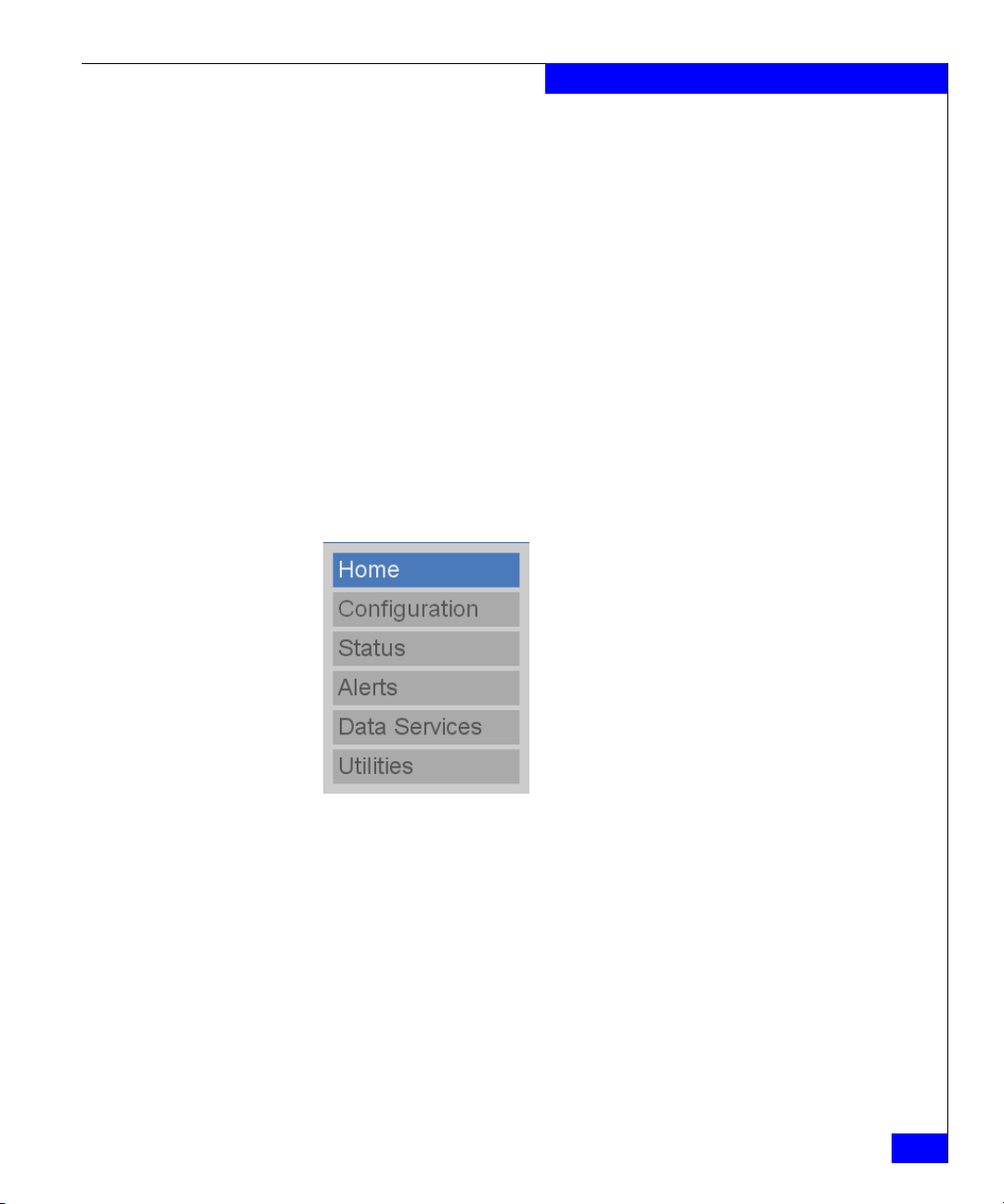
The Home page is divided into the following sections:
◆ Contents
◆ Status
◆ Data reduced by
◆ System details
◆ Virtual tape libraries data services
◆ NAS data services
◆ System status information
This section provides a menu that links to the DL3D 1500/3000 web
pages. Click the menu item to view the corresponding page. This
section is also referred to as the Contents frame.
DL3D 1500 and DL3D 3000 web pages
29
Page 30
DL3D 1500 and DL3D 3000 Remote Management
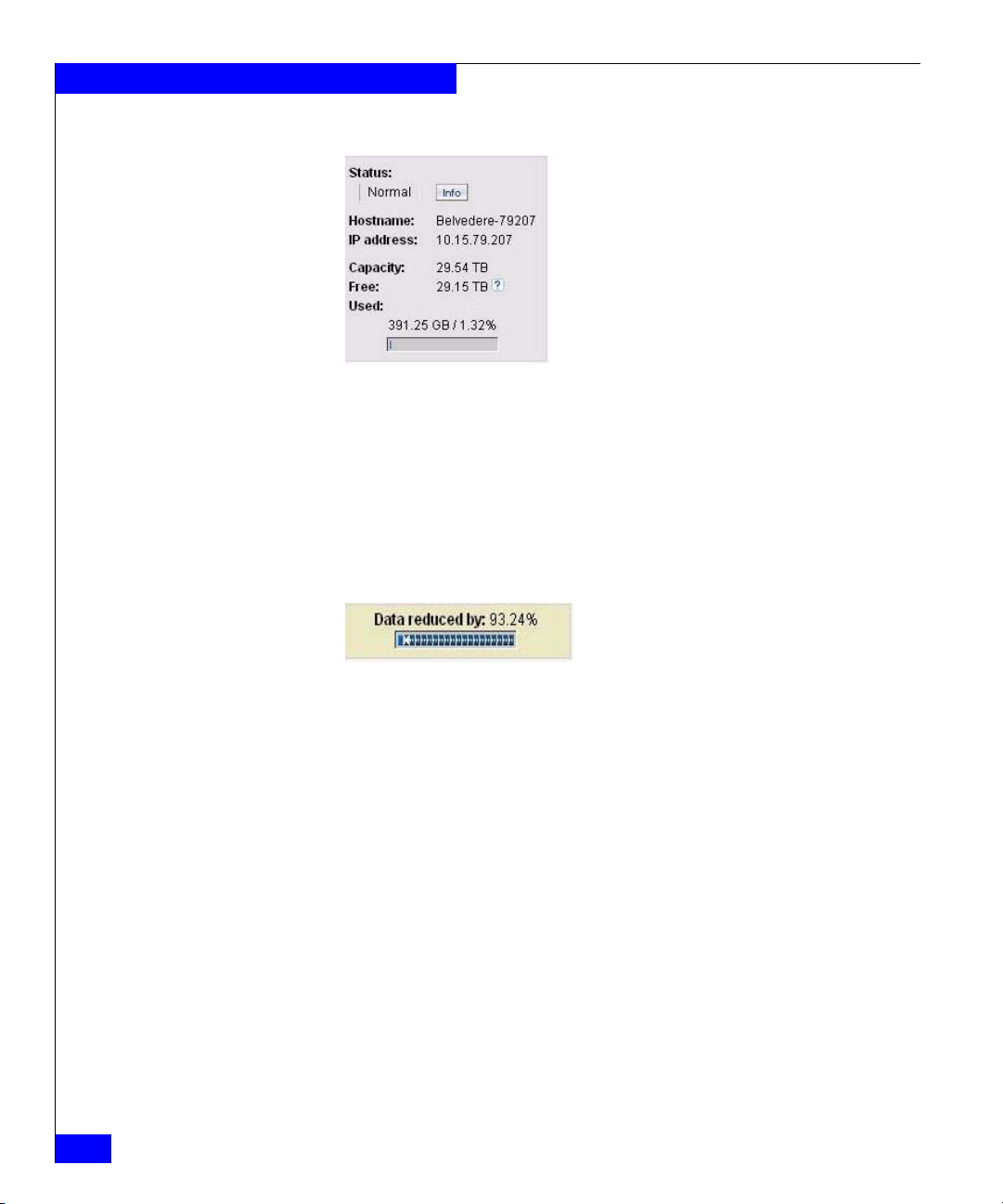
Status
This section displays the system status, hostname, IP address, and
provides storage capacity information.
◆ Capacity: Total raw data capacity available in the storage system.
◆ Free: Data capacity available for new data.
◆ Used: Data capacity consumed by data waiting to be
de-duplicated, data that will not be de-duplicated, de-duplicated
data, and metadata.
Data reduced by
30
This section displays the current data reduction status. The
percentage reduced indicates the total amount of data reduction
achieved by both hardware compression and data de-duplication.
EMC DL3D 1500 and DL3D 3000 Administrator’s Guide
Page 31

System details
DL3D 1500 and DL3D 3000 Remote Management
This section displays the DL3D model, software version, and system
serial number. The cumulative data reduction statistics area contains
details such as the original data size before reduction, the data size
after reduction, and the resulting reduction ratio. The cumulative
replication statistics area shows the amount of replicated user data
that was sent by the source system, the total amount of user
de-duplicated data that was received by the target system, and the
average send and receive rates.
DL3D 1500 and DL3D 3000 web pages
31
Page 32

DL3D 1500 and DL3D 3000 Remote Management
Virtual tape libraries data services
This section displays de-duplication and replication status for all
configured virtual tape libraries. In the De-duplication section, click
Info to view the Virtual Tape Libraries Configuration Summary
page. In the Replication section, click Info to view the Virtual Tape
Libraries Replication Status page.
NAS data services
32
EMC DL3D 1500 and DL3D 3000 Administrator’s Guide
Page 33

System status
DL3D 1500 and DL3D 3000 Remote Management
This section displays NAS share de-duplication and replication
status. In the De-Duplication section, click Info to view the NAS
Configuration Summary page. In the NAS Replication section, click
Info to view the NAS Replication Status page.
This section displays the following buttons:
◆ Admin — Enabled when an administrator alert has occurred. The
administrator alert is displayed under Admin/Alerts on the
Alerts page.
◆ Action — Enabled when an action is required on the system. The
required action information is displayed under Actions Required
on the Alerts page.
◆ Ticket — Enabled when a system status ticket is available. The
system status ticket description is available under Service Tickets
on the Alerts page.
Management frame
The management frame is the area in the home page that displays a
summary of the system details, VTL data services, and NAS data
services.
DL3D 1500 and DL3D 3000 web pages
33
Page 34

DL3D 1500 and DL3D 3000 Remote Management
34
EMC DL3D 1500 and DL3D 3000 Administrator’s Guide
Page 35

3
Configuring DL3D
1500/3000
The Configuration page lets you set or configure the following areas
of the DL3D 1500/3000 appliance. This chapter discusses configuring
the following areas:
◆ Accessing the configuration page.................................................... 36
◆ Configuring the network .................................................................. 37
◆ Configuring the date and time......................................................... 39
◆ Configuring security.......................................................................... 41
◆ Configuring email.............................................................................. 45
◆ Configuring SNMP............................................................................ 48
◆ Adding contacts information ........................................................... 52
Configuring DL3D 1500/3000
35
Page 36

Configuring DL3D 1500/3000
Accessing the configuration page
To access the Configuration page, from the contents frame, click
Configuration. The management frame displays the Configuration
page.
The Configuration page is divided into the following areas:
◆ Virtual Tape Libraries
◆ Path-to-Tape
◆ Disk Backup
•NAS
•OST
•Windows Domain
◆ Network
◆ Date & Time
◆ Security
◆ Email
◆ SNMP
◆ Contacts
36
Chapter 4, “Configuring and Managing Virtual Tape Libraries,”
contains information about configuring virtual tape libraries and
Path-to-Tape. Chapter 5, “Configuring and Managing Disk Backup,”
contains information about configuring disk backup - NAS and OST.
This chapter explains the configuration of network, date and time,
security, e-mail, SNMP, and contacts.
EMC DL3D 1500 and DL3D 3000 Administrator’s Guide
Page 37

Configuring the network
Enter the network configuration information during the initial setup
of the DL3D 1500/3000 appliance. Consult your network
administrator prior to changing any of the information.
Viewing/editing the network configuration
Use the Network Configuration page to view and edit the network
configuration information.
To access the Network Configuration page and modify network
settings:
1. On the Configuration page, click Network. The management
frame displays the Network Configuration page.
2. Select the network bonding method:
• Round Robin (Mode 0) - The data, management, and
replication traffic from the DL3D is equally distributed on all
the Ethernet ports in a sequential order using this bonding
policy.
• LACP (Mode 4) – From DL3D version 1.1, the Ethernet ports
can also be bonded using the Link Aggregation Control
Protocol (LACP) bonding. The Ethernet ports are bundled into
a single logical channel for the traffic according to the LACP
bonding policy. The policy provides greater theoretical
maximum bandwidth. This aggregation of DL3D ports
potentially improves NAS data ingest or replication
performance. The advantages of LACP include increased
bandwidth, optimal load sharing, flexibility, and transparency.
This also requires an IEEE 802.3ad compatible switch
configured for the LACP feature for ALL the ports from DL3D
connected to it.
3. Type a name for the system in the Hostname box.
Configuring DL3D 1500/3000
4. Type the IP address for the system in the IP Address box.
5. Type the network mask value in the Network Mask box.
6. Type the gateway value in the Default Gateway IP Address box.
7. If desired, type the domain name and IP addresses of up to three
DNS servers.
Configuring the network
37
Page 38

Configuring DL3D 1500/3000
8. Click Apply.
38
Figure 1 Configuring the network
Table 1 Optional network node fields
Field Description
Domain Name Domain name for the DL3D 1500/3000 appliance.
Primary/Secondary/
Domain name server IP address.
Tertiary DNS
EMC DL3D 1500 and DL3D 3000 Administrator’s Guide
Page 39

Configuring the date and time
You can set the date and time from the DL3D 1500/3000 appliance
web pages. Setting the correct date and time lets the system provide
accurate reports when events occur on the system. The date and time
may be set manually or synchronized to an NTP server.
Date and time configuration
Use the Date and Time page to set the system date and time.
To configure date and time settings using the Date and Time
Configuration page:
1. On the Configuration page, click Date & Time.
The management frame displays the Date & Time Configuration
page.
2. The two options for setting the system date and time are:
•Select Manual to manually set the system date and time using
the Edit button to select the system date from the pop-up
calendar and drop-down boxes for the system time.
•Select Use NTP (Network Time Protocol) to synchronize the
DL3D 1500/3000 appliance to an NTP server. The Select a
Server selection makes a list of well-known NTP servers such
as the U.S. Naval Observatory Master Clocks in Washington,
DC and Colorado Springs, Colorado available. The Specify
server selection enables you to type the name or IP address of
any desired NTP server. NTP sends periodic time requests to
the DL3D 1500/3000 appliance, obtaining time stamps and
using them to adjust the system’s clock.
3. Select the time zone from the Time Zone drop-down list.
Configuring DL3D 1500/3000
4. Select either a 24- or 12-hour time format.
5. Click Apply.
6. Click Yes to confirm your date and time changes. You must reboot
the system for the changes to take effect.
Configuring the date and time
39
Page 40

Configuring DL3D 1500/3000
40
Figure 2 Configuring date and time
EMC DL3D 1500 and DL3D 3000 Administrator’s Guide
Page 41

Configuring security
To access the Security page, on the Configuration page, click
Security.
The management frame displays the Security page.
The Security page is divided into three sections:
◆ Passwords
◆ SSL
◆ Login Session
Passwords
The DL3D 1500/3000 appliance has two levels of security built into
the system: monitor and administrator. The monitor user is allowed
to view the DL3D 1500/3000 remote management pages, but not
change them. The administrator user can both view and change the
management pages. This section lets you change the passwords for
these accounts.
Configuring DL3D 1500/3000
To set the monitor and administrator passwords:
1. On the Monitor Password page, type the desired password in the
New Password box and again in the Confirm New Password
box.
Note: The passwords are limited to 15 characters. All alphanumeric
characters, _, and - are allowed.
2. Click Apply.
An Information page indicates the password has been changed.
3. On the Administrator Password page, type the desired password
in the New Password box and again in the Confirm New
Password box.
Note: The passwords are limited to 15 characters. All alphanumeric
characters, _, and - are allowed.
4. Click Apply.
An Information page indicates the password has changed.
Configuring security
41
Page 42

Configuring DL3D 1500/3000
Figure 3 Configuring security - passwords
CLI administrator and monitor accounts
To change the CLI monitor or administrator account password:
42
◆ Click Reset password to factory default to restore the factory
default password for the CLI account.
◆ Click Change password to create a new password. Type the new
password and confirm the new password.
You can also select to enable or disable the CLI monitor and
administrator accounts. Click Apply to save the settings.
EMC DL3D 1500 and DL3D 3000 Administrator’s Guide
Page 43

Configuring DL3D 1500/3000
SSL
Figure 4 Configuring CLI passwords
SSL (Secure Sockets Layer) is a protocol that provides security and
privacy over the Internet by negotiating encryption keys before
transmitting data between a client and a server.
To establish a SSL connection, a certification authority must assign an
encryption key in the form of a certificate file, private key file, and
pass phrase to your DL3D 1500/3000 appliance. Once you install
these components, you can establish a secure connection using the
SSL protocol. The DL3D 1500/3000 appliance comes with an SSL
certificate; however, you can purchase other certificates and add
them to the DL3D 1500/3000 SSL configuration.
To access the SSL page and add an SSL certificate:
Configuring security
43
Page 44

Configuring DL3D 1500/3000
1. On the Security page, click SSL.
The management frame displays the SSL page.
Note: The default setting for SSL is disabled.
2. To enable SSL, select Enable and click Apply.
3. To add an SSL certificate, click New.
The Install SSL Certificate page appears.
4. In the Upload Your SSL certificate file edit box, type the location
and filename of the new SSL certificate file.
Note: Use the Browse button to browse the system and locate the
desired SSL certificate file. The SSL certificate file must be named
server.crt.
5. Click Upload to install the SSL certificate file.
6. Type your private key and press Enter.
7. Type your pass phrase and press Enter. A Successful Upload
page indicates that the SSL certificate file has been installed on the
system.
Login session
44
EMC DL3D 1500 and DL3D 3000 Administrator’s Guide
8. Click OK to continue.
The certificate is displayed in the certificate area on the SSL page.
By default, the browser session will time-out after 30 minutes of
inactivity. You can shorten or extend this time from 1 to 60 minutes
using this page.
To modify the session time out value:
1. On the Login Session page, type a value for the Inactivity
Timeout field and click Apply.
2. Click OK to confirm the change in time-out value.
Page 45

Configuring email
Recipients
Summary
Add
Configuring DL3D 1500/3000
To access the Email page, on the Configuration page, click Email.
The management frame displays the Email page.
The Email page is divided into the following sections:
◆ Recipients
◆ Server
◆ Test
Use the Recipients page to add, edit, and delete email recipients.
The Summary page lists all configured email recipients, their
notification status, and type of notifications to receive. To edit the
email recipient information, click Name or Edit.
The Add page lets you configure an email recipient.
Edit
To add an email recipient:
1. Type an email name.
2. Type an email address where the email notification will be sent.
3. Select a notification type (High, High and Medium, or All).
4. Select the notification status. When selected, this recipient will
receive notifications.
5. Click Apply.
The email recipient is added.
The Edit page lets you edit the email recipient information for a
specific recipient.
To edit an email recipient:
1. Select the recipient to edit from the Name drop-down list.
2. Change the email address, if desired.
Configuring email
45
Page 46

Configuring DL3D 1500/3000
Delete
3. Select a different notification type from the Notification Type
drop-down list, if desired.
4. Disable email notifications to the recipient by clicking on
Notifications Enabled.
5. Click Apply.
6. Click Yes to confirm the changes.
The Delete page lets you delete a previously configured email
recipient.
To delete an email recipient:
1. Select the email recipient.
2. Click Delete.
The email recipient is deleted.
46
Figure 5 Configuring email recipients
EMC DL3D 1500 and DL3D 3000 Administrator’s Guide
Page 47

Server
Test
Configuring DL3D 1500/3000
Use the Server page to specify the outgoing email server information.
1. Type the Host Name or IP address for the outgoing email(SMTP)
server (for example, the DNS name).
2. Type the email address that will appear in the From line when the
recipient receives an email from the system.
3. Click Apply.
To send a test email to verify the email configuration, select a
recipient from the list and click Send.
Configuring email
47
Page 48

Configuring DL3D 1500/3000
Configuring SNMP
Destinations
Simple Network Management Protocol (SNMP) is a set of protocols
for managing complex networks. SNMP works by sending messages,
called protocol data units (PDUs), to different parts of a network.
SNMP-compliant devices, called agents, store data about themselves
in management information bases (MIBs) and return this data to the
SNMP requesters.
To access the SNMP page, from the Configuration page, click SNMP.
The management frame displays the SNMP page.
The SNMP page is divided into the following sections:
◆ Destinations
◆ Community
◆ Test
Use the Destinations page to add, edit, or delete SNMP trap
destinations.
48
To add an SNMP destination:
1. Click Add.
2. Type the IP address that receives the SNMP traps generated by
the DL3D appliance, for example, 12.34.56.78.
3. Type the SNMP community string in the Name field.
4. Enable the trap selections to be reported.
Table 2 SNMP trap selections
Field Description
Informational Generates a trap on system-detected events.
Warning Generates a trap on system-detected warning conditions.
EMC DL3D 1500 and DL3D 3000 Administrator’s Guide
Page 49

Community
!
Configuring DL3D 1500/3000
Table 2 SNMP trap selections (continued)
Field Description
Failure Generates a trap on system-detected errors.
Available Generates a trap every time the library transitions from an
unavailable to an available state.
Unavailable Generates a trap every time the library transitions from an available
to an unavailable state.
5. Click Apply to save the destination information.
Note: Appendix A lists warning and failure events.
Use the Community page to add, edit, and delete the SNMP
community information.
1. Click Add in the Community area.
2. In Add SNMP Community, type the new community
information:
• A unique name in the Name field; the field holds up to 20
characters (a-z, A-Z) with no special characters or blank
spaces.
CAUTION
If no communities are defined, the DL3D appliance is
universally accessible through a “public” community (read
only).
• IP address in the IP Address field; if the value in the Network
Mask edit box ends in a zero, the value in the IP address edit
box must also end in a zero.
Note: An IP address of 0.0.0.0 will disable the IP address access
control for the community. Similarly, a zero in the octet of the IP
address (and corresponding network mask octet) will allow access
for the entire range of addresses in that part of the IP address. If not
disabled, the source address of an SNMP request is logically ANDed
Configuring SNMP
49
Page 50

Configuring DL3D 1500/3000
with the network mask associated with the supplied community
name, and the request will be honored if the request is equal to the IP
address entered.
• Subnet mask in the Network Mask field.
Note: A network mask of 0.0.0.0 will disable the IP address access
control for the community. If not disabled, the source address of an
SNMP request is logically ANDed with the network mask entered,
and the request will be honored if the result is equal to the network IP
address. When you want to provide access to a range of IP addresses
in the community, the network mask must have the same number of
zeroes in the same address octets as the IP address.
Examples of IP address and network mask combinations are
as follows:
– IP address: 153.203.16.65 Network mask: 255.255.16.65
This allows only server 153.203.16.65 to have access.
– IP address: 153.203.16.0 Network mask: 255.255.16.0
This allows only servers in the range of 153.203.16.xx to
have access.
50
– IP address: 153.203.0.0 Network mask: 255.255.0.0
This allows only servers in the range of 153.203.xx.xx to
have access.
– IP address: 153.0.16.0 Network mask: 255.0.16.0
This allows only servers in the range of 153.xx.16.xx to
have access.
• Access rights for the new community:
– Get allows SNMP get operations
– Get/Set allows both SNMP get and set operations
3. Select Enable to enable this SNMP community.
4. Click Apply.
An Information page is displayed indicating the community has
been added.
EMC DL3D 1500 and DL3D 3000 Administrator’s Guide
Page 51

Test
Configuring DL3D 1500/3000
Use the Te st page to send an SNMP trap:
1. Select an SNMP destination.
2. Click Send from the Te st tab.
The test trap is sent. Verify that the SNMP trap was sent at the
destination.
Figure 6 SNMP configuration - Adding trap destination
Configuring SNMP
51
Page 52

Configuring DL3D 1500/3000
Adding contacts information
Use the Contacts page to add the company contact information.
To access the Contacts page, on the Configuration page, click
Contacts. The management frame displays the Contacts.
The Contacts page is divided into these sections:
◆ Company
◆ Primary/Secondary
Company
Use the Company page to enter company-specific information.
Although these fields are optional, this information is included with
any support tickets generated and can provide valuable information
for identifying the appliance.
Edit the company information as desired (Tab le 3 contains a
description of the fields) by modifying the fields as appropriate on
this page and click Apply.
52
Table 3 Company information
Field Description
Company Name Name of the company where the DL3D 1500/3000 appliance
resides.
Street Street where the company is located.
City City where the company is located.
State State where the company is located.
Postal Code Postal code of the company location.
Country Country location.
DL3D System
Location
Support Contract Support contract number.
EMC DL3D 1500 and DL3D 3000 Administrator’s Guide
Physical location of the DL3D appliance (for example: Data
Center).
Page 53

Primary/Secondary
Table 4 Primary/secondary contact information
Configuring DL3D 1500/3000
Use the Primary/Secondary page to type primary contact
information.
Edit the primary/secondary contact information as desired (Ta bl e 4
contains a description of the fields) under the appropriate tab and
click Apply.
Field Description
Name Primary/secondary contact name.
Email Primary/secondary contact email address.
Phone Primary/secondary contact phone number.
Fax Primary/secondary contact fax number.
Pager Primary/secondary contact pager number, if available.
Street Primary/secondary contact street address.
City Primary/secondary contact city location.
State Primary/secondary contact state location.
Postal Code Primary/secondary contact postal code.
Country Primary/secondary contact country location.
Adding contacts information
53
Page 54

Configuring DL3D 1500/3000
54
EMC DL3D 1500 and DL3D 3000 Administrator’s Guide
Page 55

4
Configuring and Managing
Virtual Tape Libraries
This chapter contains information on configuring and managing
virtual tape libraries, Path-to-Tape, and auto archive features:
◆ Introduction ........................................................................................ 56
◆ Configuring virtual tape libraries.................................................... 59
◆ Managing virtual tape libraries ....................................................... 68
◆ Configuring and managing the Path-to-Tape feature................... 76
◆ Configuring Auto Archive................................................................ 82
◆ Managing auto archive...................................................................... 87
Configuring and Managing Virtual Tape Libraries
55
Page 56

Configuring and Managing Virtual Tape Libraries
Introduction
The DL3D is a target-based, specialized, hardware de-duplication
appliance. When you use this appliance with the virtual tape library
feature, you can configure it to look like a number of tape libraries
with associated tape drives to the backup servers on the SAN.
Connecting the DL3D to the SAN
The DL3D 1500 has two 4-gigabit front-end Fibre Channel ports, and
the DL3D 3000 has four 4-gigabit front-end Fibre Channel ports for
target mode SCSI attach. You must make all connections to these
ports through a Fibre Channel switch. Direct attachment of any
device to these front-end ports is not supported. The following
recommendations apply when you connect the DL3D to a backup
server through a Fibre Channel switch:
◆ When you want to emulate an EMC Disk Library, use a Fibre
Channel switch listed in the EMC Support Matrix.
◆ Avoid using hard (port) zoning schemes with backup devices.
◆ Always define a single initiator-target zoning scheme with the
world wide part name (wwpn).
Virtual tape libraries
56
EMC DL3D 1500 and DL3D 3000 Administrator’s Guide
◆ Do not use switch encryption solutions; DL3D does not support
them. This product provides an encryption feature with the
optional replication feature to meet data in-flight encryption
requirements.
◆ Limited extended fabric (ISL Link) configurations to three hops
between the backup server and the DL3D.
The DL3D virtual tape library (VTL) is an emulated library with one
or more emulated tape drives. Each VTL has a number of slots and
import/export ports for virtual media (cartridges).
You can create a total of up to 64 virtual libraries and 160 virtual tape
drives in the DL3D. Each library can have up to 9000 cartridges
associated with it. The de-duplication feature is set at the VTL level.
The VTL permits you to create combinations of any emulated library
with any emulated tape drive. However, backup software
applications for combinations that do not exist in the real world will
Page 57

Configuring and Managing Virtual Tape Libraries
not function properly when incorrect combinations of library and
tape drive types are specified. When they fail, it may not be obvious
that it is due to an invalid combination.
Note: EMC recommends creating virtual tape library and drive combinations
that are formally supported with real physical libraries/drives. See the EMC
Support Matrix for the latest supported combinations.
The number of slots defined for a particular virtual tape library is not
limited to the number found in the physical tape library it is
emulating; it is limited by the number supported by the backup
software application.
When you create tape cartridges, they are spread across the storage
LUNs in a round-robin fashion. This maximizes the performance by
spreading the I/O load across multiple LUNs. If tape cartridges are
created individually (or only a few at a time), they can potentially be
allocated to the same LUN, which results in poor overall (aggregate)
throughput.
You can customize the cartridge size, but it cannot exceed the
capacity of its physical equivalent. This ensures that the compressed
data stored on a virtual tape cartridge will fit on a physical tape once
it has been decompressed and then recompressed by the physical
tape drive. You cannot create tape cartridges larger than their
physical equivalents on the DL3D 1500 and DL3D 3000. A size of 100
GB has been found to be a good minimum virtual cartridge size.
Other considerations
If you use the Path-to-Tape feature, create virtual tape cartridges of
the same type as the physical tape used in the Physical Tape Library
(PTL), if possible, or the same virtual cartridge type used in the EDL.
If your PTL uses a tape type that the DL3D does not emulate,
configure the virtual tape cartridges as LTO-1.
The DL3D 1500 and DL3D 3000 emulate a number of
industry-standard library and tape drive types. These appliances
support the use of multiple virtual libraries and tape drives
simultaneously. To address backup bottlenecks commonly seen with
shared devices, use one of the following two approaches:
◆ Create a library and tape drives for each backup host's exclusive
use. This ensures the best possible performance by removing
delays inherent with shared tape drives.
Introduction
57
Page 58

Configuring and Managing Virtual Tape Libraries
◆ Create a single library with many tape drives, but assign only a
few tape drives to each backup server. In this configuration, each
backup server has its own dedicated resources. This also
simplifies the initial installation and avoids any driver-related
issues you may encounter when sharing a tape device between
different OS platforms.
58
EMC DL3D 1500 and DL3D 3000 Administrator’s Guide
Page 59

Configuring virtual tape libraries
To configure virtual tape libraries:
1. Access the Virtual Tape Libraries page. See “Accessing virtual
tape libraries” on page 59.
2. Create a virtual tape library and enable immediate or scheduled
de-duplication as necessary. See “Creating a virtual tape library”
on page 60.
3. Create virtual tape cartridges on the virtual tape library. See
“Managing media actions” on page 72.
4. Configure the SAN Client and target devices. See “Managing
SAN clients” on page 64 and “Managing targets” on page 65.
5. Add a SAN client group by associating the SAN Clients and
target devices with the virtual tape library. See “Managing SAN
clients” on page 64.
Accessing virtual tape libraries
Configuring and Managing Virtual Tape Libraries
To access the Virtual Tape Libraries page, from the contents frame,
click Configuration. The management frame displays the Virtual
Tape Libraries page.
The Virtual Tape Libraries page is divided into five pages:
◆ Virtual Tape Libraries
◆ Create Media
◆ Media Actions
◆ Virtual Tape Library Actions
◆ SAN Clients
The Virtual Tape Libraries page contains a list of assigned tape
drives and all user-defined virtual tape libraries currently configured
on the system. This page allows you to add, edit, and delete virtual
tape libraries.
To access the Virtual Tape Libraries Configuration page, click
Virtual Tape Libraries located at the top of the Virtual Tape Library
page. The Virtual Tape Libraries Configuration page appears.
Configuring virtual tape libraries
59
Page 60

Configuring and Managing Virtual Tape Libraries
!
Creating a virtual tape library
Creating a virtual tape library involves selecting the type of library to
emulate, the type and number of tape drives to emulate, and the
de-duplication policy.
CAUTION
Ensure that your backup application is properly configured for the
correct number of tape drives emulated in the DL3D 1500/3000
system virtual tape library. Failure to do so may cause your backup
application to malfunction or cease to operate.
To add a virtual tape library:
1. To access the Virtual Tape Libraries Configuration page, click
Virtual Tape Libraries located at the top of the Virtual Tape
Library page. The Virtual Tape Libraries Configuration page
appears.
2. On the Virtual Tape Library Configuration page, click Add to
add a virtual tape library to the system.
60
The Add Virtual Tape Library page appears.
3. Type a unique name to distinguish it from other virtual tape
libraries on the DL3D 1500/3000 appliance.
Note: The virtual tape library name is independent of the hostname in
Network tab. The section “Configuring the network” on page 37
the
contains more information.
4. Select a Library Model from the drop-down list.
5. Select the Number of Storage Slots for this virtual tape library.
Note: The number of I/E slots created will be equal to the number of
storage slots created, up to 240 I/E slots.
6. Select the Virtual Tape Drive Model available to the host and
backup application in this virtual tape library.
7. Type the number of drives for this virtual tape library.
EMC DL3D 1500 and DL3D 3000 Administrator’s Guide
Page 61

Configuring and Managing Virtual Tape Libraries
Note: If all tape drives are assigned to other virtual tape libraries, you
must edit or delete existing virtual tape libraries to make tape drives to
available for a new virtual tape library.
8. Select Enable De-Duplication to enable de-duplication for this
virtual tape library. By default, de-duplication is not enabled.
Once the virtual tape library has been created, de-duplication
cannot be enabled or disabled for this virtual tape library.
9. If you want to use scheduled de-duplication, select Enable
Backup Window and specify the backup window. De-duplication
will not occur during this time window each day. Only one
backup window may be set per virtual tape library. By default,
selecting only Enable De-duplication enables immediate
de-duplication for the virtual tape library.
a. From the list box, select the start time for the backup window.
b. From the list box, select the end time for the backup window.
Note: If de-duplication does not complete before the next backup
window occurs, de-duplication of the previous day's backup data will
continue until it finishes. This can cause your backup window to be
extended. De-duplication of the current backup will not occur until the
backup window expires.
10. Click Apply to create the virtual tape library.
The virtual tape library is added to the virtual tape library list.
Figure 7 illustrates an example of adding a virtual tape library.
Configuring virtual tape libraries
61
Page 62

Configuring and Managing Virtual Tape Libraries
Creating media
62
EMC DL3D 1500 and DL3D 3000 Administrator’s Guide
Figure 7 Adding a virtual tape library
Use the Create Media page to create virtual tape cartridges for a
specific virtual tape library. You can also set the tape cartridge
capacity, the starting barcode, and the initial location from this page.
Page 63

Configuring and Managing Virtual Tape Libraries
To create virtual tape cartridges using the Create Media page:
1. To access the Virtual Tape Libraries Configuration page, click
Virtual Tape Libraries located at the top of the Virtual Tape
Library page. The Virtual Tape Libraries Configuration page
appears.
2. On the Virtual Tape Library Configuration page, click Create
Media.
The Create Media page appears.
3. From the drop-down list, select the virtual tape library that will
contain the media you want to create.
Note: The media types available are determined by the type of drive you
selected when adding a virtual tape library. The media capacity is
determined by the cartridge type selected.
4. Either select the default capacity for the media type or specify a
custom capacity. To enter a custom capacity, select custom size
and enter the capacity for the tape cartridge.
Note: Minimum and maximum values are displayed when the cartridge
type is selected.
5. Type the number of media required for this virtual tape library.
6. Type the starting cartridge barcode.
Note: You can type any alphanumeric string for the starting barcode and
the values will be incremented accordingly. AA will become AA0000,
AA0001, AA0002, and so forth. Starting barcode values with less than 6
characters will be padded with 0s.
7. Select the initial location of the tape cartridge from the
drop-down list. The initial location is where the cartridge is
stored once it is created. The location can be either an
import/export (I/E) slot or library slot.
Note: You cannot create cartridges with an initial location greater than
the number of available slots. For example, if 50 I/E slots are available,
you cannot create 60 cartridges with the initial location of I/E slots.
8. Click Apply to create the media.
Configuring virtual tape libraries
63
Page 64

Configuring and Managing Virtual Tape Libraries
The cartridges are available on the DL3D 1500/3000 for that
virtual tape library.
Figure 8 Creating media
Managing SAN clients
64
EMC DL3D 1500 and DL3D 3000 Administrator’s Guide
Until you assign a virtual library to a SAN client, the backup servers
cannot use it. To ensure correct library behavior and device discovery
when assigning or unassigning, ensure that device numbering on the
bus starts with LUN 0 and no LUN numbering holes exist. LUN
numbering holes can occur when devices are unassigned.
Use the SAN Clients page to discover and add Fibre Channel SAN
clients to the available host list for the DL3D appliance.
Page 65

Managing targets
Configuring and Managing Virtual Tape Libraries
Note: You must add a SAN client to the SAN client list before you can
associate a SAN client group with a virtual tape library.
To add a SAN client:
1. On the SAN Client Access page, click SAN Clients. The SAN
Clients page appears.
2. Click Refresh SAN Clients to display the available hosts.
3. For a Fibre Channel host, type the World Wide Port Name
(WWPN) in the WWPN box.
4. Type an alias for the new host in the Alias box.
5. Click Apply to add the host.
The new SAN client is added.
Use the Target page to view the current target (Fibre Channel)
configuration.
Viewing target usage
To access the Target page:
1. On the SAN Client Access page, click Ta r ge t .
The Target page appears.
2. Click the Ty pe list box to view the Fibre Channel targets.
The Fibre Channel targets display the Node, Alias, and WWPN for
the currently configured targets.
Use the Target Usage page to view the current target and device
mappings for the node.
To access the Target Usage page:
1. On the SAN Client Access page, click Target Usage.
The Target Usage page appears.
2. Click the Node list box to view the Node target mappings.
Configuring virtual tape libraries
65
Page 66

Configuring and Managing Virtual Tape Libraries
The Fibre Channel ports are listed with the virtual devices
(Virtual Medium Changer and Virtual Tape Drives) mapped to
the ports.
Adding a SAN client group
Use SAN client groups to allow backup hosts to access virtual devices
on your system. SAN client groups are associated with a virtual tape
library, SAN Client (Fibre Channel initiator on your SAN), and port
(Fibre Channel target on your system). From that association, the
SAN client can access one or more devices in the virtual tape library
through different SAN client LUNs on the port. If you have to allow
multiple SAN Clients to access devices of the same virtual tape
library, you must create separate SAN client groups for each SAN
client.
Use the Add page to add a SAN client group to a specific virtual tape
library.
To add a SAN client group using the Add page:
1. To access the SAN Client Access page, on the Virtual Tape
Libraries section, click SAN Client Access. The SAN Client
Access page appears.
66
2. On the SAN Client Access page, click Add.
The Add page appears.
3. To add a host access group to a virtual tape library:
a. Select a virtual tape library from the VTL drop-down box.
b. Type a group name for the SAN client.
c. Select a host from the Host drop-down box.
Note: You must configure a host before adding a SAN client group.
d. Select a Fibre Channel port from the Ta r ge t list box.
e. Select the media changer and tape drives that you would like
added to the SAN client.
The LUN assignment is displayed next to the device.
4. Click Apply to add the SAN client group.
The SAN client group is added.
EMC DL3D 1500 and DL3D 3000 Administrator’s Guide
Page 67

Single library with multiple hosts
You must use the DL3D to create different groups for each host so
that multiple hosts can use the same devices. A group consists of
exactly one host, one target, and one or more devices. The DL3D does
not permit multiple hosts to access the same group.
Configuring and Managing Virtual Tape Libraries
Configuring virtual tape libraries
67
Page 68

Configuring and Managing Virtual Tape Libraries
Managing virtual tape libraries
You can manage the virtual tape libraries in the following ways:
◆ To change the de-duplication mode from immediate to schedule
and vice versa, or to change the backup window for scheduled
de-duplication, see “Editing a virtual tape library” on page 68.
◆ To delete a virtual tape library, see “Deleting a virtual tape
library” on page 69.
◆ To place a VTL in the offline or online state, or move its media
from a slot/drive/or IE slot, or unload media, see “Managing
virtual tape library actions” on page 70.
◆ To view all the available virtual tape cartridges and their details
or export, recycle, delete, or import virtual media, see “Managing
media actions” on page 72.
◆ To view a list of SAN clients, see “Managing SAN client groups”
on page 74.
◆ To edit SAN client groups, see “Editing a SAN client group” on
page 75.
Editing a virtual tape library
68
EMC DL3D 1500 and DL3D 3000 Administrator’s Guide
◆ To delete SAN client groups, see “Deleting a SAN client group”
on page 75.
Editing an existing virtual tape library consists of changing its
de-duplication mode (immediate or scheduled), and backup window
(for scheduled de-duplication). To edit a virtual tape library:
1. Set the DL3D 1500/3000 virtual tape library to be edited to the
offline state. The section “Changing the mode” on page 70
contains more information.
2. On the Virtual Tape Libraries Configuration page, select the
virtual tape library to edit or click Edit.
The Edit Virtual Tape Library page appears.
3. Edit the virtual tape library information as desired.
4. Click Apply.
Page 69

5. Return the DL3D 1500/3000 virtual tape library to the online
state. The section “Changing the mode” on page 70 contains more
information.
The virtual tape library is updated.
Viewing virtual tape libraries
To access the Virtual Tape Libraries Configuration page, click
Virtual Tape Libraries located at the top of the Virtual Tape Library
page. The Virtual Tape Libraries Configuration page appears.
The Summary page displays the maximum number of virtual tape
libraries, the maximum number of tape drives, and the number of
assigned tape drives. The Summary page also provides a list of
configured virtual tape libraries on the system. Select a virtual tape
library in the Name column to edit it.
Note: Click this information icon to view additional virtual tape library
information such as the policy-based backup window, start and end times,
and the replication schedule.
Configuring and Managing Virtual Tape Libraries
Deleting a virtual tape library
You cannot delete a virtual tape library which has media in it. You
must first delete the media and make sure that the virtual tape library
is in offline mode. To delete virtual media, see “Managing virtual
actions on the media” on page 73.
To delete a virtual tape library:
1. Set the DL3D 1500/3000 virtual tape library to be deleted to the
offline state and remove any media that is present in its drives.
The section “Changing the mode” on page 70 contains more
information.
2. On the Virtual Tape Libraries Configuration page, click Delete.
3. Select the virtual tape library to delete and click Delete.
4. Click Yes to confirm the delete operation.
The virtual tape library is deleted.
Managing virtual tape libraries
69
Page 70

Configuring and Managing Virtual Tape Libraries
Managing virtual tape library actions
You can change the mode of a virtual tape library from offline to
online state or online to offline state. You can move the media from a
drive or I/E slot to a drive or I/E slot on the same virtual tape library.
You can also unload media from the tape drives or I/E slots.
Changing the mode Use the Mode page to turn individual virtual tape libraries online or
offline.
To change the mode of virtual tape libraries using the Mode page:
1. On the Virtual Tape Library Actions page, click Mode.
The Mode page appears.
The Mode page lists all of the configured virtual tape libraries on
the DL3D 1500/3000 appliance. The Virtual Tape Library Name,
Current Mode (online or offline), and Serial Number are
displayed.
Note: Click the information icon to view additional virtual tape
library information such as the policy-based backup window start and
end times as well as the replication schedule.
70
2. To turn a virtual tape library online, select the virtual tape library
and click Apply. To turn a virtual tape library offline, uncheck the
virtual library and click Apply.
3. Click Yes to confirm the mode change.
The virtual tape library mode is changed to reflect the new online
or offline status.
Moving the tape
cartridge
Use the Move page to move a tape cartridge from a source (slot, port,
or drive) to a destination (slot, port, or drive). The destination must
be in the same virtual tape library. The virtual tape library must be
offline in order to move the media.
To move a tape cartridge:
1. On the Virtual Tape Library Actions page, click Move. The Move
page appears.
EMC DL3D 1500 and DL3D 3000 Administrator’s Guide
Page 71

Configuring and Managing Virtual Tape Libraries
2. In the Source section:
a. Select the source virtual tape library from the drop-down list.
If the virtual tape library is online, click Offline to take it
offline.
b. Select the location type to display (Slot, Drive, I/E Slot) from
the Show Location Type drop-down list.
c. Select the tape cartridge in the source virtual tape library to
move.
d. To force drives to unload prior to moving a tape cartridge,
select the Force Unload (Drives).
3. In the Destination section:
a. Select the location type to display (Slot, Drive, I/E Slot).
b. Select the destination location for the tape cartridges being
moved.
Note: The Destination section lists empty storage slots, I/E slots, and
drives. Offline drives are NOT included in the list. Drives may be offline
if they have not been mapped to a host.
Hint:Click the Quick Tip icon
next to the Barcode Filters edit
box for examples of acceptable
barcode filters.
Unloading the tape
cartridge
4. To reduce the number of tape cartridges displayed on the Move
page, type a barcode that the system can use to filter the tape
cartridges. For example, typing LTO in the Barcode Filter edit box
displays tape cartridges with a barcode beginning with LTO.
5. Click Apply.
6. Click Yes to confirm the Move operation.
The tape cartridges are moved.
Use the Unload page to unload a tape cartridge from a source (I/E
slot or drive) and return it to its original slot in the library. If that is
unknown, it returns it to the first available slot.
To unload media:
1. On the Virtual Tape Library Actions page, click Unload.
2. Select the source virtual tape library from the list box.
3. Click Offline to turn the virtual tape library offline.
Managing virtual tape libraries
71
Page 72

Configuring and Managing Virtual Tape Libraries
Note: The virtual tape library must be offline before unloading a tape
cartridge.
4. Select the location type to be displayed (Drive or I/E Slot).
5. To force drives to unload prior to receiving a tape cartridge, click
Force Unload (Drives).
6. Select the tape drive or I/E slot in the virtual tape library to be
unloaded.
7. To reduce the number of tape cartridges displayed on the Unload
page, type a barcode that the system can use to filter the tape
cartridges. For example, typing LTO in the Barcode Filter,
displays tape cartridges with a barcode beginning with LTO.
Hint:Click the Quick Tip icon
next to the Barcode Filters edit
box for examples of acceptable
barcode filters.
8. Click Apply.
9. Click Yes to confirm the unload operation.
The tape cartridge is unloaded.
Managing media actions
72
Use the Media Actions page to import, export, and remove virtual
tapes and cartridges from a virtual tape library. This page also
provides access control over virtual cartridges.
To access the Media Actions page, on the Virtual Tape Libraries
Configuration page, click Media Actions.
The Media Actions page is divided into the following sections:
◆ Summary
◆ Virtual Actions
Summary The Summary page displays all virtual cartridges defined in the
system. To access the Summary page, on the Media Actions page,
click Summary. The Summary page appears.
EMC DL3D 1500 and DL3D 3000 Administrator’s Guide
Page 73

Note: You can click the Barcode, VTL, Media Type, Access Pool, Used (%),
and Capacity (GB) column headings to sort the rows by the data in the
respective column. Click the column heading again to invert the sorting
sequence from ascending order to descending order. Click the information
icon to view additional cartridge information such as previous and
current position.
The Summary page lists the information as described in Ta ble 5.
Table 5 Summary Information
Column Description
Barcode Displays the barcode number for the tape cartridge.
Virtual Tape Library Displays the virtual tape library name where the tape cartridge is
Type Displays the tape cartridge type - LTO or SDLT.
Access Displays the tape cartridge state - scratch or used.
Configuring and Managing Virtual Tape Libraries
located.
Managing virtual
actions on the media
Pool Displays the type of cartridge pool such as application, cleaning,
service, or unknown.
Used (%) Displays the percentage of cartridge that is used.
Capacity (GB) Displays the total capacity of the tape cartridge.
Use the Virtual Actions page to perform specific actions on the
virtual tape cartridges in the DL3D 1500/3000. To access the Virtual
Actions page, on the Media Actions page, click Virtual Actions. The
Virtual Actions page appears.
Note: You can click the Barcode, VTL, Write Protect, State, Used (%), and
Capacity (GB) column headings to sort the rows by the data in the respective
column. Click the column heading again to invert the sorting sequence from
ascending order to descending order. Click the information icon to view
additional cartridge information such as previous and current position.
Managing virtual tape libraries
73
Page 74

Configuring and Managing Virtual Tape Libraries
Table 6 Virtual actions
Field Description
Delete Deletes tape cartridges from the virtual tape library. Selected
media must be in exported state.
Export Places the virtual tape cartridge in a vaulted state, making it
Recycle Recycles tape cartridges so that the virtual tape library can
Write Protect (WP) Lets you enable or disable write protection for tape cartridges.
To perform the virtual actions:
1. Select the library containing the media.
2. Select the media on which the action is to be performed
(individual, all, by barcode).
3. Select the action (Delete, Export, Recycle, Write Protect).
4. Click Apply.
Managing SAN client groups
Use the Groups page to view the SAN client groups associated with a
specific virtual tape library. You can have more than one SAN client
group associated with a single virtual tape library.
unavailable for use by the library. The virtual tape cartridge
can be deleted from the virtual tape library or later imported
into the library.
reuse them. Selected cartridges must be in the virtual state.
You cannot scratch media to write protected.
74
To access the Groups page:
1. To access the SAN Client Access page, on the Virtual Tape
Libraries page, click SAN Client Access. The SAN Client Access
page appears.
2. On the SAN Client Access page, click Groups.
The Groups page appears.
3. Click the virtual tape library drop-down box to view the host
groups associated with the configured virtual tape libraries.
EMC DL3D 1500 and DL3D 3000 Administrator’s Guide
Page 75

Editing a SAN client group
Deleting a SAN client group
Configuring and Managing Virtual Tape Libraries
Use the Edit page to edit a SAN client group.
To edit a SAN client group:
1. On the SAN Client Access page, click Edit. The Edit page
appears.
2. Select a virtual tape library from the Virtual Tape Library list box.
3. Select a group name from the Group Name list box.
4. Select or clear the media changer and tape drives that you must
add to the host group. The LUN assignment is displayed next to
the device.
5. Click Apply to save the changes to the SAN client group.
The SAN client group is saved.
Use the Delete page to delete a SAN client group from a virtual tape
library.
To delete a SAN client group:
1. On the SAN Client Access page, click Delete. The Delete page
appears.
2. Select a virtual tape library from the Virtual Tape Library list box.
3. Select a group name from the Group Name list box.
4. Click Delete to remove the SAN client group.
The SAN client group is removed from the virtual tape library
association.
Managing virtual tape libraries
75
Page 76

Configuring and Managing Virtual Tape Libraries
Configuring and managing the Path-to-Tape feature
The Path-to-Tape (PTT) feature is a licensed option of the EMC DL3D
and is used for duplicating backup images from virtual cartridges in
the DL3D onto media in an attached physical tape library (PTL) or
EMC Disk Library VTL. You cannot use this feature to copy NAS
backups - CIFS shares or NFS mount points - to tape.
Note: The Path-to-Tape feature is licensed. You must upload the license key
to use this functionality. See “License keys” on page 172 for information
about uploading the license keys.
Setting up the Path-to-Tape function
A DL3D 3000 system has four Fibre Channel ports for SAN attaches
and a DL3D 1500 has two Fibre Channel ports. The default roles of
these ports are target ports. When you install the DL3D's
Path-to-Tape license or Auto Archive license, one port, FC Port 3,
becomes an initiator port. This initiator port is used to attach a
physical tape library or an EDL VTL that the PTT feature will use.
76
1. Install the DL3D VTL license on the DL3D.
2. Install the DL3D PTT license and Auto Archive license on the
DL3D. The presence of this license changes FC Port 3 from a
target port to an initiator port.
3. Connect the DL3D's FC Port 3 and the physical tape library or the
EDL VTL you will be using to a Fibre Channel switch.
4. Zone FC Port 3 to the physical tape library or EDL VTL you will
be using as the Path-to-Tape storage unit.
While connecting to the SAN:
◆ Use single initiator, single target zoning by soft zoning.
◆ Avoid hard port zoning practices with backup devices.
◆ If this is a physical tape library or VTL with multiple FC target
ports, make a separate zone for each port for each initiator (DL3D
and media server).
◆ Once the PTT license has been installed/enabled, FC Port 3 on the
DL3D is configured as an initiator port to support the PTT
function and cannot be reconfigured as a target port.
EMC DL3D 1500 and DL3D 3000 Administrator’s Guide
Page 77

Configuring the Path-to-Tape function
Use the Path-to-Tape (PTT) Configuration page to configure the
backup application specific server.
The PTT Configuration page is divided into the following sections:
◆ Device Discovery
◆ Auto Archive
◆ Vendor Specific
Discovering physical devices
You must discover and configure attached physical libraries before
using a backup application or auto archive. Use the Physical Device
Discovery page to discover and configure attached physical libraries.
Note: PTT options can be configured only when the Backup Application
Specific PTT license has been enabled (see “License keys” on page 172).
To access the Physical Device Discovery page, on the PTT page, click
Physical Device Discovery.
Configuring and Managing Virtual Tape Libraries
To configure an attached physical library:
Note: Click a Media Changer in the list to display the associated tape drive
and details, such as serial number, product ID, vendor, drive type, and the
intended use.
1. Click Scan for Devices to detect attached physical libraries. Any
attached physical libraries are shown in the Medium Changers
(Physical Libraries) list.
2. Select the new attached library by clicking the library serial
number checkbox.
3. Select an intended use for this library from the drop-down menu:
• Backup Application Specific - when selected, the library will
be used as a backup application specific server. The settings
depend on the backup application that you use.
• Remove - removes the attached library from the DL3D
configuration.
Configuring and managing the Path-to-Tape feature
77
Page 78

Configuring and Managing Virtual Tape Libraries
!
CAUTION
The physical library must be physically disconnected from
the DL3D before it can be removed from the configuration.
• Ignore - when selected, the system will ignore this attached
physical library.
4. Click Apply.
The changes are applied.
Figure 9 Discovering physical devices
To view the library media changer and configured drives, click the
Serial Number link for the library.
The tape drives are shown in the Tape Drives list.
78
EMC DL3D 1500 and DL3D 3000 Administrator’s Guide
Page 79

Select an intended use for the tape drives:
!
◆ Backup Application Specific - when selected, the tape drive will
be used as a backup application specific server. The settings
depend on the backup application that you use.
◆ Remove - removes the tape drive from the DL3D 3000
configuration.
CAUTION
The tape drive MUST be physically disconnected or removed
from the DL3D before it can be removed from the
configuration.
◆ Ignore - when selected, the system will ignore this tape drive.
Configuring backup application-specific users
You must specify a backup application specific username and
password for the backup software so that it can log in to the DL3D
1500/3000 and use the Path-to-Tape feature. To configure backup
application specific users:
Configuring and Managing Virtual Tape Libraries
1. Discover attached physical devices. See “Discovering physical
devices” on page 77. Change the intended use to backup
application specific usage.
2. Access and view backup application specific users. See
“Accessing and viewing backup application-specific users” on
page 79.
3. Add a backup application specific user. See “Adding a backup
application specific user” on page 80.
Accessing and viewing backup application-specific users
Use the Backup Application Specific page to configure the backup
application specific user configuration settings.
To access the Backup Application Specific page, on the
Configuration page, click Backup Application Specific. The Backup
Application Specific User Configuration page appears.
Configuring and managing the Path-to-Tape feature
79
Page 80

Configuring and Managing Virtual Tape Libraries
The Backup Application Specific User Configuration page is
divided into the following sections:
◆ Summary
◆ Add
◆ Edit
◆ Delete
The Summary page lists all backup application specific users on the
system.
Adding a backup application specific user
To add a backup application specific user:
1. To access the Backup Application Specific page, on the
Configuration page, click Backup Application Specific. The
Backup Application Specific User Configuration page appears.
2. Click Add.
The Add Vendor Specific User page appears.
3. Type the following backup application specific user information:
a. Type a username.
b. Type a password.
c. Confirm the password.
d. Add a description (optional).
e. Click Apply to add the backup application specific user.
Managing backup application specific user
You can manage the backup application user settings in the following
ways:
◆ Edit a backup application specific user. See “Editing a backup
application specific user” on page 81.
◆ Delete a backup application specific user. See “Deleting a backup
application specific user” on page 81.
80
EMC DL3D 1500 and DL3D 3000 Administrator’s Guide
Page 81

Editing a backup application specific user
To edit a backup application specific user:
1. To access the Backup Application Specific Configuration page,
on the Configuration page, click Backup Application Specific.
The Backup Application Specific User Configuration page
appears.
2. Click Edit. The Edit Backup Application Specific User page
appears.
3. Edit the following backup application specific user information:
a. Select the backup application specific username you want to
edit.
b. Edit the password.
c. Confirm the password.
d. Add a description (optional).
e. Click Apply to save the changes.
Deleting a backup application specific user
To delete a backup application specific user:
Configuring and Managing Virtual Tape Libraries
1. To access the Backup Application Specific page, on the
Configuration page, click Backup Application Specific. The
Backup Application Specific User Configuration page appears.
2. Click Delete. The Delete Backup Application Specific User page
appears.
3. Select the backup application specific users you want to delete.
4. Click Apply to delete the selected backup application specific
users.
The backup application specific users are deleted.
Configuring and managing the Path-to-Tape feature
81
Page 82

Configuring and Managing Virtual Tape Libraries
!
Configuring Auto Archive
You can configure attached physical libraries using the Auto Archive
page. Once configured, the libraries are recognized and available to
the DL3D system for data backups.
CAUTION
The DL3D cannot support a physical tape library with mixed media
in a single partition.
Note: You must enable the Auto Archive license to configure the physical
libraries. See “License keys” on page 172 for information on uploading the
license keys.
The Auto Archive page is divided into the following sections:
◆ Media
◆ Behaviors
◆ Devices
To configure Auto Archive:
1. Discover attached physical devices. See “Discovering physical
devices” on page 77. Change the intended use to Auto Archive.
2. Claim media. See “Claiming media” on page 82.
3. Set Import/Export behavior. See “Setting import/export behavior
of media” on page 84.
4. Set up early tape creation. See “Configuring early tape creation”
on page 85.
5. Configure barcode filters. See “Configuring barcode filters” on
page 86.
Claiming media
Use the Claim Media page to assign media options to unknown
media, as follows:
1. To access the Media page, click Auto Archive on the PTT page.
2. On the Media page, click Claim Media. The Claim Media page
appears.
3. Select the cartridges from the unknown media list.
82
EMC DL3D 1500 and DL3D 3000 Administrator’s Guide
Page 83

Configuring and Managing Virtual Tape Libraries
4. Select the Media Pool type (Application or Cleaning).
Application media will store data. Cleaning media can be used
only to clean a tape drive.
5. Select the Application Media Options:
a. Select the partition where you will assign the cartridges.
b. Select the Import Behavior that will determine the access for
the media the next time it is imported into the system.
– Scratch - Creates blank virtual media; does not import data
from physical media.
– Virtual - Creates virtual media; imports data from physical
media.
– Direct Access - Creates virtual media, but any data is
written directly to corresponding physical media and is not
written to virtual media.
c. Select the Initial Location that defines the initial location for
the media in the partition.
– I/E Slot - Sets the media initial location to an I/E slot in the
partition.
– Storage Slot - Sets the media initial location to a storage
slot in the partition.
d. Select the Export Behavior that defines what happens to the
physical media when its corresponding virtual media is
exported from the partition.
– I/E Slot - Sends the media to the I/E slot of a physical
library for removal from library.
– Storage Slot - Sends the media to a storage slot in a
physical library and takes the media offline.
6. Click Apply.
The Claim Media actions are performed.
Configuring Auto Archive
83
Page 84

Configuring and Managing Virtual Tape Libraries
Figure 10 Claiming media
Setting import/export behavior of media
Use the Behaviors pages to manage the import/export settings,
configure early tape creation, and configure barcode filters.
To access the Import/Export Behaviors page:
1. On the Configuration page, click PTT.
2. On the PTT page, click Auto Archive.
3. On the Auto Archive page, click Behaviors.
4. On the Behaviors page, click Import/Export.
The Import/Export Media page is divided into two sections - Import
Behavior and Export Behavior.
84
EMC DL3D 1500 and DL3D 3000 Administrator’s Guide
Page 85

Managing import behavior
Configuring and Managing Virtual Tape Libraries
The Import Behavior section specifies the default access assigned to a
cartridge the next time it is imported into the system. The default
import behavior is used for all virtual tape libraries. Changes to this
setting will apply to all future cartridge import operations. The four
import options are:
◆ Virtual - Selecting this option will change the cartridge access
type to virtual. Data from the physical cartridge with a matching
barcode is transferred to a corresponding virtual cartridge.
◆ Direct Access - Selecting this option will change the cartridge
access type to direct access. Data passes through the DL3D 3000
and is written to a corresponding physical cartridge. It is NOT
written to virtual cartridge.
◆ Unknown - Selecting this option will return the cartridge to the
unknown pool with an unknown access. This option is used to
manually assign access and pool (cleaning, service, or
application).
To change the default import behavior for individual media, see
“Managing virtual actions on the media” on page 87.
Managing export behavior
The Export Behavior specifies the physical destination when virtual
cartridge is exported from system. The two export behavior options
are:
◆ I/E Slot - Sends the cartridge to an I/E slot in the physical library.
◆ Storage Slot - Sends the cartridge to a storage slot in the physical
library and takes the cartridge offline.
To change export behavior for media already in the system, see
“Managing virtual actions on the media” on page 87.
Configuring early tape creation
Early tape creation is a way to generate a physical copy of virtual
cartridge before an export operation. Early tape creation allows
export operations to complete faster.
Note: Early tape creation applies only to virtual cartridges with a physical
counterpart in an attached tape library. If the virtual cartridge does not have a
physical counterpart, early tape creation does not generate a physical copy.
Configuring Auto Archive
85
Page 86

Configuring and Managing Virtual Tape Libraries
To access the Early Tape Creation page, on the Behaviors page, click
Early Tape Creation. The Early Tape Creation page appears.
Early tape creation is enabled all day by default. It is recommended
that this process run in the background while no other processes,
such as backups, are running.
To set early tape creation for a specific time:
1. Click the Enable Early Tape Creation All Day checkbox to
uncheck it.
2. Use the drop-down boxes to set the start time and end time for
the early tape creation window.
Configuring barcode filters
The barcode filter indicates the physical cartridges used for drive
cleaning. The Barcode Filter page displays the barcode filters.
To access the Barcode Filters page, on the Behaviors page, click
Barcode Filters. The Barcode Filters page appears.
Cleaning Barcode Filters
The cleaning barcode filter indicates the physical cartridges used for
drive cleaning.
86
The ? special character will match any individual character.
The * special character will match any number of characters.
Advanced filter examples:
TSM? - Will match any single alphanumeric character
following TSM, i.e. TSM0, TSMA, etc.
TSM* - Will match any number of characters following TSM,
i.e. TSM12, TSM12345, etc.
TSM.... - Will match exactly four characters following
TSM
TSM.+ - Means one or more characters are required to
match
TSM0* - Means that zero or more 0`s are required to
match, i.e. TSM00000
TSM[0-9] - Will match TSM1
TSM[0-9]*- Will match TSM1111111111
TSM[0-9]{3} - Will match TSM and three digits exactly
EMC DL3D 1500 and DL3D 3000 Administrator’s Guide
Page 87

Managing auto archive
You can manage auto archive in the following ways:
◆ View the media summary. See “Viewing media summary” on
page 87.
◆ Manage virtual actions on the media. See “Managing virtual
actions on the media” on page 87.
◆ Manage cartridge access. See “Managing cartridge access” on
page 89.
◆ Manage physical actions on the media. See “Managing physical
actions on the media” on page 90
◆ Manage pending actions. See “Managing pending actions” on
page 91.
◆ Manage device modes. See “Managing device modes” on
page 92.
Viewing media summary
Configuring and Managing Virtual Tape Libraries
Use the Media page to import, export, and remove virtual and
physical cartridges from a physical library. This page also provides
access control over virtual cartridges.
The Summary page allows you to view all cartridges in the system,
both virtual and physical.
Managing virtual actions on the media
The Virtual Actions page allows you to perform specific actions on
the tape cartridges in the DL3D system.
To perform virtual actions on the cartridges:
1. To access the Media page, click Auto Archive on the PTT page.
2. On the Media page, click Virtual Actions. The Virtual Actions
page appears.
Managing auto archive
87
Page 88

Configuring and Managing Virtual Tape Libraries
3. Select a virtual action to perform:
• Archive Data - This action moves a virtual tape cartridge to a
physical tape cartridge and retains a virtual copy in the virtual
tape library after the move is complete. Selected cartridges
may be in identical states.
• Delete - This action deletes tape cartridges from the partition.
Selected media must be in exported state.
Note: You must remove the physical tapes before deleting the virtual
tapes.
• Export - This action moves a virtual tape cartridge to a
physical tape cartridge. The virtual copy of the tape cartridge
will be deleted from the partition after the move is complete.
This action should be performed in the event that an export
cannot be performed from the backup application. Selected
cartridges may be in archived, direct access, identical, scratch
or virtual state. Export is available only for virtual cartridges
with barcodes matching barcodes in physical library.
• Export Behavior - This action assigns an export rule to the
selected cartridges. The available export rules are I/E station
or storage slot. The action is available only for virtual
cartridges with barcodes that match barcodes in physical
library. It applies only to cartridges that are not purely virtual
and they must have a corresponding physical cartridge.
• Import Behavior - This action assigns an access state to the
selected tape cartridges when they are imported back into the
DL3D 3000 system. The available access rules are: Scratch,
Direct Access, or Virtual. This action is available only for
virtual cartridges with barcodes that match barcodes in
physical library. It applies only to cartridges that are not
purely virtual and they must have a corresponding physical
cartridge.
To reduce the number of tape cartridges displayed on the Virtual
Actions page, enter a barcode that the system can use to filter the
tape cartridges. For example, entering LTO in the Barcode Filter
edit box displays only tape cartridges with barcodes beginning
with LTO.
88
EMC DL3D 1500 and DL3D 3000 Administrator’s Guide
Page 89

4. Click Apply.
The selected cartridge actions are performed.
Managing cartridge access
The Change Access page lists cartridges in the physical library and
allows you to change the access type.
Configuring and Managing Virtual Tape Libraries
If you are assigning Import Behavior, select the rule from the
drop-down box. The available rules are Scratch, Direct Access, or
Virtual. If the Import Behavior radio button is not selected, this
drop-down box is unavailable.
Note: This behavior will not be changed until the next time the cartridge
is imported.
If you are assigning Export Behavior, select the rule from the
drop-down box. The available rules are I/E Station or Slot. If the
Export Behavior action is not selected, this drop-down box is
unavailable.
Note: Change access can be configured only if the Path-to-Tape license has
been enabled.
To change the access type of the cartridges:
1. Access the Media page by clicking Auto Archive on the PTT
page.
2. On the Media page, click Change Access.
3. Select the checkbox to choose a tape cartridge from the list. To
reduce the number of tape cartridges displayed on the Change
Access page, type a barcode that the system can use to filter the
tape cartridges. For example, entering LTO in the Barcode Filter
edit box displays only tape cartridges with barcodes beginning
with LTO.
4. Select the desired access type:
• Direct Access - Selecting this option will change the cartridge
access type to Direct Access. Data passes through the DL3D
3000 and is written to a corresponding physical cartridge. It is
not written to the virtual cartridge.
Managing auto archive
89
Page 90

Configuring and Managing Virtual Tape Libraries
• Scratch - Selecting this option will change the cartridge access
type to Scratch. Data on the virtual cartridge will be lost.
• Unknown - Selecting this option will return the cartridge to
the Unknown Pool with an Unknown Access. This option is
used to manually assign access and pool (cleaning or
application).
• Virtual - Selecting this option will change the cartridge access
type to Virtual.
5. Click Apply.
The access type of the cartridge is changed.
Managing physical actions on the media
The Physical Actions page allows you to import or export tape
cartridges to and from a physical library.
Note: Physical actions can be configured only when the Path-to-Tape license
has been enabled.
To access the Media page, click Auto Archive on the PTT page. To
access the Physical Actions page, on the Media page, click Physical
Actions. The Physical Actions page appears.
90
Importing media The Import section imports offline and unknown media from a
physical library's storage slot into a virtual library. To import offline
or unknown media from a physical library into the virtual library
partition:
1. To reduce the number of tape cartridges displayed on the Import
page, enter a barcode that the system can use to filter the tape
cartridges. For example, entering LTO in the Barcode Filter edit
box displays tape cartridges with barcodes beginning with LTO.
2. Select the checkbox next to the media you want to import into the
virtual tape library.
3. Select the virtual tape library where you want the imported
media to be located.
4. Select the Import Behavior to be assigned to the selected media
when imported into the DL3D system. The available access rules
are Scratch, Virtual, or Direct.
EMC DL3D 1500 and DL3D 3000 Administrator’s Guide
Page 91

Configuring and Managing Virtual Tape Libraries
!
5. Select an Initial Location where the imported cartridge will be
located. The available locations are I/E station or Storage Slot.
6. Click Apply.
The selected tape cartridges are imported into the virtual tape library.
Exporting media The Export page allows you to export offline media from a virtual
partition to a physical library. The data from the virtual tape cartridge
is written to a physical tape cartridge and then moved to an
import/export station on the physical library.
CAUTION
If you export virtual media with data written to it and there is no
corresponding physical media to write the data to, the data on the
virtual media is lost. If you recycle the virtual media, the data is
discarded and lost.
To export offline media in a physical library to a physical library
export station:
1. To reduce the number of tape cartridges displayed on the Export
page, enter a barcode that the system can use to filter the tape
cartridges. For example, entering LTO in the Barcode Filter edit
box displays only tape cartridges with barcodes beginning with
LTO .
2. Select the checkbox next to the media you want to export to a
physical library export station.
3. Click Apply.
The offline cartridge is moved to the library export station.
Managing pending actions
The Pending Actions page lists media with a pending action that
may be cancelled.
To access the Media page, click Auto Archive on the PTT page. To
access the Pending Actions page, in the Physical section, click
Pending Actions. The Pending Actions page appears.
Managing auto archive
91
Page 92

Configuring and Managing Virtual Tape Libraries
To cancel a pending action:
1. To reduce the number of tape cartridges displayed on the
Pending Actions page, enter a barcode that the system can use to
filter the tape cartridges. For example, entering LTO in the
Barcode Filter edit box displays only tape cartridges with
barcodes beginning with LTO.
2. Select the checkbox next to the barcode with a pending action you
wish to cancel.
3. Click Cancel Action.
Managing device modes
The Devices page is used to control the mode (online or offline) of the
attached physical libraries and tape drives.
Physical libraries and drives will not be displayed until they have
been integrated using the Physical Device Discovery page (see
“Discovering physical devices” on page 77).
Changing library modes
The Library page allows you to turn the library online or offline.
Changing drive modes
92
EMC DL3D 1500 and DL3D 3000 Administrator’s Guide
To access the Library page, on the Devices page, click Library. The
Library page appears.
The Library page lists all of the configured physical libraries on the
DL3D system. The Library Name, Current Mode (online or offline),
Model, Serial Number, and Media are displayed.
To turn a library online or offline, select the library and click Apply.
The library mode is changed to reflect the new online or offline
status.
The Drive page allows you to turn the tape drive online or offline.
To access the Drive page, on the Devices page, click Drive. The Drive
page appears.
The Drive page lists all of the configured physical tape drives on the
DL3D system. The Drive Name, Serial Number, Tape Drive Type,
Current Mode (online or offline), Mount State, Mount Count, and
Library Name are displayed.
Page 93

Configuring and Managing Virtual Tape Libraries
To turn a tape drive online or offline, select the tape drive and click
Apply. The tape drive mode is changed to reflect the new online or
offline status.
Managing auto archive
93
Page 94

Configuring and Managing Virtual Tape Libraries
94
EMC DL3D 1500 and DL3D 3000 Administrator’s Guide
Page 95

5
Configuring and Managing
Disk Backup
The configuration page lets you set or configure the following areas
of the DL3D 1500/3000 appliance:
◆ Configuring and managing disk backup........................................ 96
◆ Configuring and managing NAS shares ........................................ 97
◆ Configuring and managing OST ................................................... 109
Configuring and Managing Disk Backup
95
Page 96

Configuring and Managing Disk Backup
Configuring and managing disk backup
The Disk Backup page is used to configure NAS shares as well as
OST storage servers.
The Disk Backup page is divided into the following sections:
◆ NAS Configuration
• Windows Domain Configuration
• Access Control Configuration
◆ OST Configuration
96
EMC DL3D 1500 and DL3D 3000 Administrator’s Guide
Page 97

Configuring and managing NAS shares
The DL3D is designed to be a target-based, specialized, hardware
de-duplication appliance that you can configure to present an NFS
share or CIFS share to the backup server. NAS backup-to-disk (B2D)
shares can be configured as CIFS or NFS shares. Both can exist at the
same time and up to 128 total shares can exist.
Configuring NAS shares
Use the NAS page to configure NAS shares. To access the NAS page,
on the Disk Backup Configuration page, click NAS.
Note: Make sure the node is online before continuing with the NAS
configuration.
The NAS section is used to add, edit, or delete NAS shares. The NAS
page is divided into the following sections:
◆ Summary Page
Configuring and Managing Disk Backup
◆ Add NAS Share
◆ Edit NAS Share
◆ Delete NAS Share
To configure NAS shares:
1. Configure a Windows domain. See “Configuring a Windows
domain” on page 98.
2. Configure access control. See “Configuring access control” on
page 102.
3. Create an NFS or CIFS share on the DL3D. This share will be
mounted (or mapped) as a backup device on the backup server. If
desired, you can create multiple shares to store different
collections of save sets. See “Adding NAS shares” on page 104.
4. Mount (or map) the share on the backup server.
• Create a mount point for the NFS share that the backup
application will use and mount the share using the commands
for your particular operating system. See “Mounting NFS
shares” on page 222.
Configuring and managing NAS shares
97
Page 98

Configuring and Managing Disk Backup
Configuring a Windows domain
Use the Windows Domain section to configure the Windows domain
information.
Note: Make sure that your system has the date and time set correctly and is
synchronized with your domain controller.
1. Click Windows Domain to configure the Windows domain
2. Edit the Windows Domain information to join a workgroup or an
The Windows Domain information is divided into the following
sections:
◆ Joining a Windows Workgroup
◆ Joining a Windows Domain
◆ Joining a Domain using a Domain User Credential
• Map the CIFS share to a drive in Windows Explorer. See
“Mapping CIFS shares” on page 225.
information.
The Windows Domain page appears.
Active Directory domain.
Joining a Windows workgroup
98
EMC DL3D 1500 and DL3D 3000 Administrator’s Guide
◆ Troubleshooting ADS Join Issues
To join a Windows workgroup:
1. Edit the page information as follows:
a. Domain Type - Select the workgroup.
b. Domain/Workgroup Name - Type the workgroup name. This
can be the name of an existing workgroup or a new
workgroup (for example, Wor kgroup or Sales).
2. Click Apply.
Note: When a Samba server is joined to a workgroup, the share security is
managed directly from the remote management pages. For a CIFS share,
security is provided through the read only or read/write access to the share.
By default, when a CIFS share is created the default security setting allows
access for all users. Further access restrictions on individual users can be
managed from the following page: NAS > Shares > Edit.
Page 99

Figure 11 Claiming media
Joining a Windows domain
Configuring and Managing Disk Backup
You must synchronize the server clock and the ADS server to make
sure that the time difference is less than 300 seconds. Make sure both
servers use the same NTP server. Once the clocks have been verified:
1. Edit the Windows Domain information as desired:
• Domain Type - Select Active Directory.
• Domain/Workgroup Name - Type the domain name.
• Primary Domain Controller - Type the fully qualified name of
the Primary Domain Controller (PDC). Choose one of these
options
– Use DNS discovery - Let the PDC be discovered
automatically.
– Type the fully qualified name, or the IP address of the PDC.
• Organization Unit (Optional) - Type the name of the
organizational unit in the domain. This is the organization
where the DL3D will become the member.
• Administrator Name - Type Administrator or any user who
has the right to join a domain. By default any user belonging
to the Administrators group or the Domain Admins group
has the right to join the domain. In addition, any domain user
can join the domain if a member of the Administrators group
has specifically delegated this right to the user.
Configuring and managing NAS shares
99
Page 100

Configuring and Managing Disk Backup
• Administrator Password - Type the administrator password.
• Confirm the administrator password - Retype the password to
confirm.
2. Click Apply.
Note: When the system is joined to the Active Directory domain, the MMC
(Microsoft Management Console) that is running on the domain controller
manages all share security. By default, when a CIFS share is created, the
default security setting allows access for all users. Any access restriction on
individual users must be managed from the MMC.
Joining a domain using a domain user credential
Many large companies do not want to use the Administrator account
to enable users to join the ADS domain. They prefer to give special
rights for joining the domain to a normal domain user account. This
section illustrates how to do this.
In this example, the following information is assumed:
◆ The ADS is running on a Windows 2003 Server system.
◆ ADS domain name is abc.def.xyz.com
100
◆ User1 is a normal domain user that has no administrative
privileges.
◆ The server hostname is DL3D1.
◆ The DNS domain name is abc.def.xyz.com
◆ The DNS IP address is 10.20.30.40
On the Windows 2003 MMC:
1. Delegate the right to join the domain:
a. Select the domain name abc.def.xyz.com
b. Right-click and select Delegate Control.Click Add.
c. Type the username: user1
d. Click OK.
e. Delegate the following common tasks. Join a computer to the
domain.
f. Click Finish.
EMC DL3D 1500 and DL3D 3000 Administrator’s Guide
 Loading...