

Page 1

DD640, DD670, DD860, and
DD890 Disk Drive Replacement
Backup Recovery Systems Division
EMC Data Domain
2421 Mission College Boulevard, Santa Clara, CA 95054
866-WE-DDUPE; 408-980-4800
775-0221-0003 Revision A
August 9, 2013
Page 2

Copyright © 2011-2013 EMC Corporation, Inc. All Rights Reserved.
EMC believes the information in this publication is accurate as of its publication date. The
information is subject to change without notice.
THE INFORMATION IN THIS PUBLICATION IS PROVIDED “AS IS.” EMC
CORPORATION MAKES NO REPRESENTATIONS OR WARRANTIES OF ANY KIND
WITH RESPECT TO THE INFORMATION IN THIS PUBLICATION, AND
SPECIFICALLY DISCLAIMS IMPLIED WARRANTIES OF MERCHANTABILITY OR
FITNESS FOR A PARTICULAR PURPOSE.
Use, copying, and distribution of any EMC software described in this publication
requires an applicable software license.
EMC, Data Domain, and Global Compression are registered trademarks or trademarks of
EMC Corporation in the United States and/or other countries.
All other trademarks used herein are the property of their respective owners.
2
Page 3
DD640, DD670, DD860, and DD890 Disk
Drive Replacement
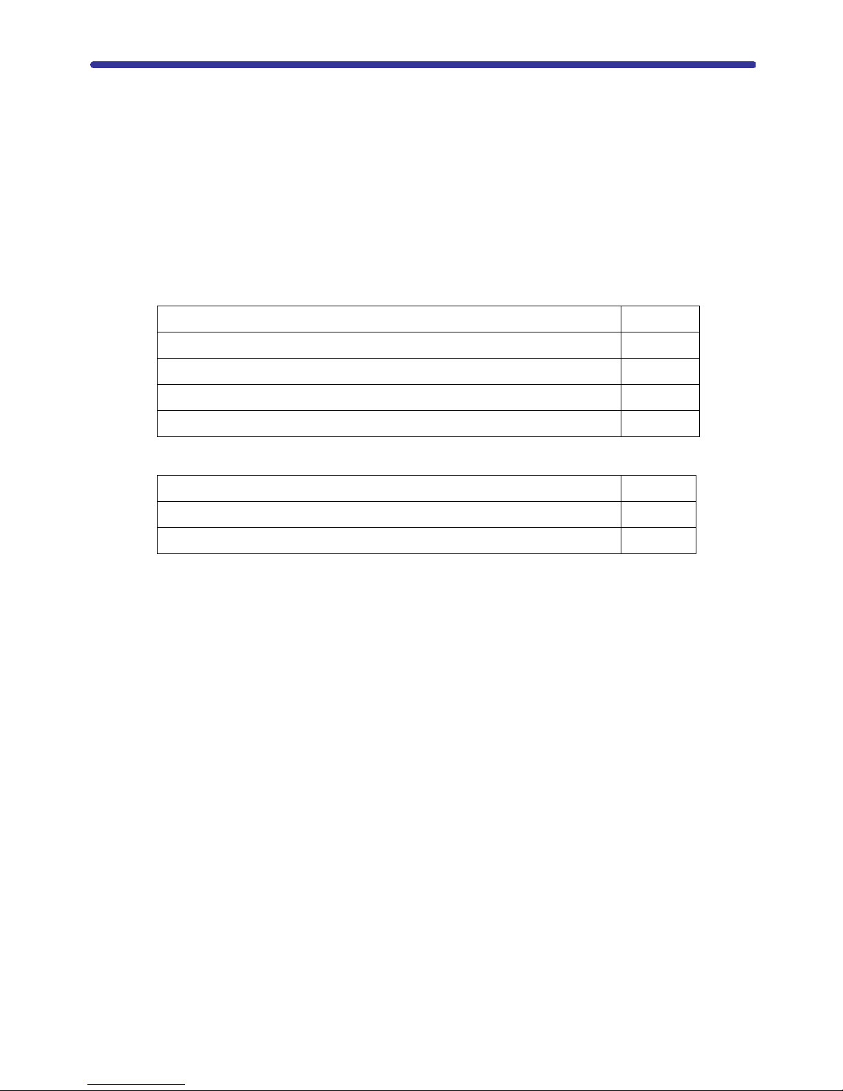
This document provides instructions for replacing the internal disk drives of EMC Data
Domain DD640, DD670, DD860, and DD890 systems. This document covers the topics
shown in the following table:
Related Documentation Page 4
Tools and Supplies Needed Page 4
Overview Page 5
Preparing for Disk Drive Replacement Page 6
Disk Drive Replacement Page 7
You can also go directly to the procedures indicated in the table below:
Identify the failed disk drive Page 6
Remove the failed disk drive Page 7
Install the replacement disk drive Page 8
DD640, DD670, DD860, and DD890 Disk Drive Replacement 3
Page 4

Related Documentation
Note: Hard copies of this document may be out of date. Always check for the current
version of this document on the Support Documentation Website.
The Documentation page at https://my.datadomain.com/documentation provides
access to three categories of documents that are related to use of Data Domain products:
• End user documents, under Product Documentation.
• Documents about how to integrate Data Domain systems with third party backup
applications, under Integration Documentation.
• Matrices that show which components are compatible with each other, under
Compatibility Matrices.
View Data Domain documents
1. Log into the support portal at: https://my.datadomain.com/documentation.
2. To view user documents, click Product Documentation and then perform the
following steps:
a. Select the Data Domain model from the Platform list and click View.
b. On the row for the correct Data Domain operating system (DD OS) version, click
View under Documentation.
c. Click the desired title.
3. To view integration-related documents, perform the following steps:
a. Click Integration Documentation.
b. Select the vendor from the Vendor menu.
c. Select the desired title from the list and click View.
4. To view compatibility matrices, perform the following steps:
a. Click Compatibility Matrices.
b. Select the desired title from the Product menu and click View.
Tools and Supplies Needed
For a list of recommended tools and supplies for field work, see the document FE Toolkit
Inventory and Common Procedures for FRU Tasks at
Documentation page, select Parts Installation Guide, then select the Data Domain product
from the menu. This document is included in the list of documents for the product.
https://my.datadomain.com. From the
4 DD640, DD670, DD860, and DD890 Disk Drive Replacement
Page 5

Overview
Table 1 shows the disk drive specifications for the DD640, DD670, DD860, and DD890
systems.
Tab le 1: Disk Drive Specification
Model Number of
Disk Drives
DD640 7 1-7
DD640 12 1-12
DD670 12 1 - 12
DD860 4 1, 2, 4, and 5
DD890 4 1, 2, 4, and 5
Disk Drive Bay
Numbers
Note: The DD640 is available as a 7-drive or 12-drive system.
Disk drive slots are numbered top down in each column, starting at the top left as shown
in Figure 1. Unused disk drive slots contain blank carriers.
Figure 1: DD640 and DD670 Disk drive numbers
Figure 2: DD860 and DD890 Disk Drive Numbers
Note: Some Data Domain systems have less than 12 disks. All disk drive bays must
contain a carrier with a disk drive installed in it or a carrier with an air baffle installed.
The disk drive carriers contain LED indicators to display the disk drive status.
Figure 3: Disk drive carrier
DD640, DD670, DD860, and DD890 Disk Drive Replacement 5
Page 6

Tab le 2: Disk Drive Carrier LEDs
LED State Description
Blue (bright) Disk drive present
Blue (dim or
blinks)
Amber Disk drive fault
Off (not lit) No disk drive present
Disk drive activity
Note: If the amber LED is on (alert or fault) and the disk drive is also powered on (blue),
the combination of the two colors is light purple (fuchsia).
Preparing for Disk Drive Replacement
Caution:
Only trained and qualified personnel should install or replace this equipment.
Identify the failed disk drive
To display the disk drive hardware status, use the disk show reliability-data
command. The display is similar to the following. The first twelve entries in the display
are the twelve disk drives in the chassis (for a DD670 system or a 12-drive DD640
system):
# disk show reliability-data
Disk ATA Bus Reallocated Temperature
(enc/disk) CRC Err Sectors
---------- ------- ----------- -----------
1.1 0 0 32 C 90 F
1.2 0 0 32 C 90 F
1.3 0 0 32 C 90 F
1.4 0 0 32 C 90 F
1.5 0 0 33 C 91 F
1.6 0 0 33 C 91 F
1.7 0 0 32 C 90 F
1.8 0 0 31 C 88 F
1.9 0 0 33 C 91 F
1.10 0 0 33 C 91 F
1.11 0 0 33 C 91 F
1.12 0 0 32 C 90 F
---------- ------- ----------- ---------- 12 drives operating normally.
Notes:
• DD860 or DD890 output shows only information about its four disk drives. A
DD640 7-drive system shows only information about its seven disk drives.
• Always replace a failed disk drive as soon as possible. A DD860 or DD890 system
can run with two live disk drives and no spare, but another disk drive failure
disables the system. A DD640 system has one hot spare and either 6 or 11 usable
disks in a RAID-6 configuration and a DD670 has one hot spare and 11 usable
6 DD640, DD670, DD860, and DD890 Disk Drive Replacement
Page 7

disks in a RAID-6 configuration. After the first disk drive failure, the hot spare
becomes active. If a DD640 or DD670 has two failed drives and no spare is
available, the system becomes disabled.
The system assigns a disk drive state to a replacement disk drive depending on the
history of the disk drive. Use the
disk show state command to display the state of all
disk drives. See Step 6 on Page 8 for sample command output.
• A Data Domain field replaceable unit disk drive is labeled as Spare.
• A disk drive that was on another system as a spare is labeled as Spare.
• A disk drive that was on another system and that contained data is seen as Foreign.
The
disk unfail command moves the disk drive to the state of Spare. Be sure that
the data on the disk drive is not needed elsewhere before giving the
command.
Disk Drive Replacement
Follow the procedures in this section to remove and replace a failed disk drive.
Remove the failed disk drive
1. If the disk drive that you want to replace is not marked as Failed in output from the
disk show state command, use the following command (with the correct disk-id)
to fail the disk drive.
disk unfail
# disk fail <enclosure id> <disk-id>
2.
Identify the physical disk drive. The lower LED on a failed disk drive glows a steady
amber, blue, or fuschia. Amber marks the disk as failed, but a failed disk might also
show blue or fuschia. If you cannot identify the failed disk from its LED, use the
following commands to identify a disk drive by name and then flash the LED on the
disk drive:
# disk show state
# disk beacon <enclosure id> <disk-id>
Cautions:
• Whenever servicing parts in a running system, move slowly while inserting and
latching the new parts. This avoids creating strong vibrations in the chassis which
might interfere with nearby operating disk drives.
• To ensure proper airflow and cooling, all disk drive bays must contain either a
carrier with a disk drive installed in it or a carrier with an air baffle installed.
3. Slide the gray disk drive carrier ejector latch to the right to release the ejector handle.
See Figure 4.
Figure 4: Removing a disk drive
DD640, DD670, DD860, and DD890 Disk Drive Replacement 7
Page 8

4.
Pull on the handle to slide the failed disk drive out about an inch, until it is
disengaged from the backplane.
5. Carefully remove the disk drive from the chassis.
Install the replacement disk drive
Caution: Allow a minimum of at least one minute between removal of the old disk and
insertion of the new disk.
1. Remove the replacement disk drive from the packaging and remove the disk drive
from the antistatic bag.
2. On the replacement disk drive carrier, make sure that the handle is pulled open.
3. With the disk drive carrier handle in the open position, carefully slide the disk drive
carrier all the way into the same disk drive bay location in the chassis until it stops.
4. Use the handle to push the carrier until it docks in the chassis, then close the handle.
Use care to avoid excessive force that could damage the replacement disk drive.
Note: If the disk exhibits excessive force to install, remove the disk drive from the bay
and repeat the installation. Never force-fit the drive into the chassis.
5. If the disk drive still shows as failed, enter the following command (with the correct
disk-id):
# disk unfail <enclosure id> <disk-id>
6.
Use the following command to check that the system recognizes the disk drive. In the
command display, the disk drive
should be
reconstructing.
State should be spare or the Additional Status
Note: A DD640 7-disk system displays information for only seven drives. The DD860
and DD890 displays information for only four disk drives.
Enclosure 1 in the following display is representative of the DD640 or DD670, twelve disk
drive systems. Enclosure 2 displays information for external shelves.
# disk show state
Enclosure Disk
1 2 3 4 5 6 7 8 9 10 11 12 13 14 15
--------- ---------------------------------------------
1 . . . . s . . . . . . .
2 . . . . . . . . . . . . . s .
--------- ---------------------------------------------
Legend State Count
------ ------------ -----
. In Use Disks 25
s Spare Disks 2
------ ------------ -----
Total 27 disks
8 DD640, DD670, DD860, and DD890 Disk Drive Replacement
Page 9

7.
Inform those who receive the autosupport reports that the disk drive replacement is
done.
# autosupport send
8.
Return the failed or replaced disk drive to Data Domain. Reuse the packaging from
the new disk drive and use the included prepaid waybill for shipping. Reference the
RMA number on the outside of the package. Returns with no RMA number cannot be
accepted.
DD640, DD670, DD860, and DD890 Disk Drive Replacement 9
Page 10

10 DD640, DD670, DD860, and DD890 Disk Drive Replacement
 Loading...