

Page 1

EMC® Data Domain® DS60 Expansion
Shelf Installation and FRU Replacement
Hardware Guide
302-002-099
REV. 02
Page 2

Copyright © 2015-2017 EMC Corporation All rights reserved.
Published January 2017
Dell believes the information in this publication is accurate as of its publication date. The information is subject to change without notice.
THE INFORMATION IN THIS PUBLICATION IS PROVIDED “AS-IS.“ DELL MAKES NO REPRESENTATIONS OR WARRANTIES OF ANY KIND
WITH RESPECT TO THE INFORMATION IN THIS PUBLICATION, AND SPECIFICALLY DISCLAIMS IMPLIED WARRANTIES OF
MERCHANTABILITY OR FITNESS FOR A PARTICULAR PURPOSE. USE, COPYING, AND DISTRIBUTION OF ANY DELL SOFTWARE DESCRIBED
IN THIS PUBLICATION REQUIRES AN APPLICABLE SOFTWARE LICENSE.
Dell, EMC, and other trademarks are trademarks of Dell Inc. or its subsidiaries. Other trademarks may be the property of their respective owners.
Published in the USA.
EMC Corporation
Hopkinton, Massachusetts 01748-9103
1-508-435-1000 In North America 1-866-464-7381
www.EMC.com
2 EMC Data Domain DS60 Expansion Shelf Installation and FRU Replacement Hardware Guide
Page 3

CONTENTS
Figures
Tables
Chapter 1
Chapter 2
7
11
Preface 13
Revision history 15
Technical Specifications 17
Disk drive type............................................................................................ 18
Network cabling.......................................................................................... 18
System operating limits...............................................................................18
Shipping and storage requirements.............................................................19
Dimensions and weight................................................................................19
Shelf Installation and Removal 21
Shelf installation......................................................................................... 22
Installing rails................................................................................. 22
Working with the portable lift........................................................ 25
Reconfiguring the lift with Voyager kit.......................................... 26
Adjusting the arms for a frontal lift................................................ 27
Installing the shelf onto the rails.................................................... 27
Inserting and securing the top cover and chassis........................... 31
Shelf removal............................................................................................. 35
Working with the portable lift........................................................ 35
Planning your lift........................................................................... 35
Removing the front bezel.............................................................. 36
Pulling the shelf chassis out...........................................................37
Removing a shelf from the cabinet................................................ 38
Using the lift on a shelf more than 49" above the floor.................. 44
Using the Lift on a shelf 49" or less above the floor.......................48
1U cable management tray installation (underneath)..................................52
Racks and rails...............................................................................52
Installing the 1U cable management tray........................................53
Disconnecting cables for an shelf installed with the 1U cable
management tray.......................................................................... 59
1U cable tray removal................................................................................. 59
Removing the 1U cable tray........................................................... 59
Non-EMC rack installation..........................................................................62
Shelf rail installation in non-EMC racks......................................... 62
Removing the universal rails....................................................................... 74
Chapter 3
EMC Data Domain DS60 Expansion Shelf Installation and FRU Replacement Hardware Guide 3
Removing and Replacing FRUs 75
Common procedures ..................................................................................76
Avoiding electrostatic discharge (ESD) damage ........................... 76
Emergency procedures (without an ESD kit).................................76
Page 4

CONTENTS
Hardware acclimation times........................................................... 77
Removing, installing, or storing replaceable units...........................78
Unpacking a part............................................................................79
Standard touch point colors...........................................................79
Power supply replacement......................................................................... 80
Identify the failed power supply unit..............................................80
Removing a power supply unit........................................................81
Replacing a power supply............................................................... 81
Verify the power supplies.............................................................. 82
Complete the procedure................................................................ 83
LCC replacement........................................................................................83
Identify the failed ..........................................................................83
Removing an LCC.......................................................................... 84
Replacing an LCC.......................................................................... 84
Verify the ......................................................................................85
Complete the procedure................................................................86
Disk replacement........................................................................................86
Identify the failed drive..................................................................86
Opening the console...................................................................... 89
Removing the front bezel.............................................................. 89
Pulling the shelf chassis out.......................................................... 90
Removing a disk drive.....................................................................91
Installing a disk.............................................................................. 92
Verify the operation of the new disk drive .................................... 93
Installing the front bezel................................................................ 94
Complete the procedure................................................................ 94
Fan replacement.........................................................................................94
Identify the failed fan unit..............................................................94
Removing the front bezel.............................................................. 95
Pulling the shelf chassis out...........................................................96
Removing a fan module................................................................. 96
Installing a fan................................................................................97
Verify the fans............................................................................... 98
Installing the front bezel................................................................ 99
Complete the procedure................................................................99
Chassis removal..........................................................................................99
Working with the portable lift........................................................ 99
Reconfiguring the lift with Voyager kit.........................................100
Adjusting the arms for a frontal lift............................................... 101
Removing a power supply unit......................................................102
Removing an LCC.........................................................................103
Opening the console.....................................................................104
Removing the front bezel............................................................. 104
Removing a disk drive.................................................................. 105
Removing a fan module................................................................ 106
Removing a shelf from the cabinet............................................... 107
Chassis replacement..................................................................... 113
Installing the front bezel...............................................................128
DS60 bezel replacement........................................................................... 128
Removing the front bezel............................................................. 128
Installing the front bezel...............................................................129
DS60 cable management assembly (CMA) bezel...................................... 129
Removing the CMA front bezel.................................................... 129
Installing the CMA front bezel......................................................130
DS60 cable management assembly (CMA) replacement...........................130
Removing the 1U cable tray..........................................................130
4 EMC Data Domain DS60 Expansion Shelf Installation and FRU Replacement Hardware Guide
Page 5

CONTENTS
Installing the 1U cable tray............................................................133
Connecting cables to the shelf..................................................... 137
DS60 rail replacement............................................................................... 137
Working with the portable lift....................................................... 137
Reconfiguring the lift with Voyager kit......................................... 138
Adjusting the arms for a frontal lift...............................................138
Removing a power supply unit......................................................139
Removing an LCC.........................................................................140
Opening the console..................................................................... 141
Removing the front bezel..............................................................141
Removing a disk drive...................................................................142
Removing a fan module................................................................ 143
Removing a shelf from the cabinet............................................... 144
Removing the universal rails..........................................................151
Installing rails............................................................................... 152
Installing the shelf onto the rails...................................................155
Inserting and securing the top cover and chassis......................... 159
Replacing a power supply............................................................. 163
Replacing an LCC......................................................................... 163
Installing a disk............................................................................. 164
Installing a fan.............................................................................. 165
Connecting cables to the shelf..................................................... 166
Verify the chassis replacement.....................................................167
Installing the front bezel...............................................................167
DS60 cable management assembly (CMA) rail replacement..................... 167
1U cable tray removal................................................................... 167
1U cable management tray installation (underneath)....................170
Chapter 4
Adding Disks 177
Verify system health..................................................................................178
Identify the first empty disk pack in the target enclosure..........................178
Locate the target enclosure in the rack.....................................................179
Opening the console..................................................................................179
Removing the front bezel.......................................................................... 179
Pulling the shelf chassis out...................................................................... 180
Add new disks............................................................................................181
Close the shelf chassis.............................................................................. 182
Verify and configure the new storage........................................................182
Installing the front bezel........................................................................... 185
EMC Data Domain DS60 Expansion Shelf Installation and FRU Replacement Hardware Guide 5
Page 6

CONTENTS
6 EMC Data Domain DS60 Expansion Shelf Installation and FRU Replacement Hardware Guide
Page 7

FIGURES
1
2
3
4
5
6
7
8
9
10
11
12
13
14
15
16
17
18
19
20
21
22
23
24
25
26
27
28
29
30
31
32
33
34
35
36
37
38
39
40
41
42
43
44
45
46
47
48
49
50
51
52
Rail installation........................................................................................................... 23
Installing the right rail to the rear channel ..................................................................24
Installing the right rail to the front channel ................................................................ 25
Reconfiguring the portable lift with the Voyager conversion kit ................................ 26
Adjusting the lift arm bar to just under 17 inches ........................................................27
Sliding the shelf chassis into the rails ........................................................................ 29
Unlocking the casters................................................................................................. 29
Locking the casters.................................................................................................... 30
Removing the straps...................................................................................................30
Inserting and securing the chassis to the cabinet........................................................ 31
Inserting and Securing the Chassis to the Cabinet (Shoulder Screw Configuration)
................................................................................................................................... 32
Removing semi-captive screws...................................................................................32
Installing ears to rack using truss head screws........................................................... 33
Installing top cover using truss head screws...............................................................34
Removal of semi-captive screws................................................................................ 35
Best Practice: Using the portable lift adjacent to the long side of the shelf................36
Removing the front bezel ...........................................................................................37
Pulling the Chassis Out (Two shoulder Screw Configuration).....................................38
Example of adjusting the lift arm/tray to just under 17-inches....................................39
Releasing chassis from the rails.................................................................................. 40
Removing the shipping screws, if present.................................................................. 40
Pulling the chassis out (two shoulder screw configuration).........................................41
Reconfiguring the Alum-A-Lift with the conversion kit................................................41
Locking the casters.................................................................................................... 42
Removing a shelf from rails more than 49" above the floor ........................................43
Tightening the straps..................................................................................................44
Unlocking the casters................................................................................................. 44
Adjusting the arm for a high rail position.....................................................................45
Locking the Casters....................................................................................................46
Removing a Shelf from rails more than 49" above the floor ....................................... 46
Tightening the straps..................................................................................................47
Unlocking the casters................................................................................................. 47
Support table..............................................................................................................48
Removing the straps...................................................................................................48
Adjusting the arm for a low rail position...................................................................... 49
Locking the casters.................................................................................................... 50
Removing a shelf from rails 49" or less above the floor ............................................. 50
Tightening the straps.................................................................................................. 51
Unlocking the casters..................................................................................................51
Removing the straps...................................................................................................52
Blue tab on rail must be pushed in.............................................................................. 53
Installing/Securing rails - front................................................................................... 54
Installing/Securing rails - rear.................................................................................... 54
Installing tray..............................................................................................................55
Spring Clips - push up to release tray......................................................................... 55
Opening the cable chain lids....................................................................................... 55
Cable positioning in cable chains................................................................................ 56
1-Inch graduation label................................................................................................56
Attaching cable chains to tray.................................................................................... 57
Installing the chassis bracket into the shelf................................................................ 57
Installing the chassis bracket......................................................................................58
Installing the bezel......................................................................................................58
EMC Data Domain DS60 Expansion Shelf Installation and FRU Replacement Hardware Guide 7
Page 8

FIGURES
53
54
55
56
57
58
59
60
61
62
63
64
65
66
67
68
69
70
71
72
73
74
75
76
77
78
79
80
81
82
83
84
85
86
87
88
89
90
91
92
93
94
95
96
97
98
99
100
101
102
103
104
105
106
107
Remove the bezel.......................................................................................................59
Remove chassis bracket from chassis........................................................................ 60
Remove the chassis bracket.......................................................................................60
Unclip the cable chains from the tray..........................................................................61
Push spring clips up to release the tray.......................................................................61
Remove the tray.........................................................................................................62
Screw and nut placements......................................................................................... 63
18"-22" marking..........................................................................................................64
26"-30" Marking........................................................................................................ 65
30"-34" Marking........................................................................................................ 65
Rail installation........................................................................................................... 68
Securing a rail with a single screw ............................................................................. 70
Location of securing screws and alignment pins ......................................................... 71
Nutbar installation (Left nutbar shown)......................................................................73
Removing the universal rails....................................................................................... 74
Opening the console...................................................................................................89
Removing the front bezel .......................................................................................... 90
Pulling the Chassis Out (Two shoulder Screw Configuration)..................................... 91
Removing a disk drive.................................................................................................92
Installing a disk........................................................................................................... 93
Removing the front bezel .......................................................................................... 95
Pulling the Chassis Out (Two shoulder Screw Configuration).................................... 96
Reconfiguring the portable lift with the Voyager conversion kit ................................101
Adjusting the lift arm bar to just under 17 inches ...................................................... 102
Opening the console..................................................................................................104
Removing the front bezel .........................................................................................105
Removing a disk drive............................................................................................... 105
Example of adjusting the lift arm/tray to just under 17-inches.................................. 108
Releasing chassis from the rails................................................................................ 109
Removing the shipping screws, if present................................................................. 109
Pulling the chassis out (two shoulder screw configuration)....................................... 110
Reconfiguring the Alum-A-Lift with the conversion kit.............................................. 110
Locking the casters.................................................................................................... 111
Removing a shelf from rails more than 49" above the floor .......................................112
Tightening the straps.................................................................................................113
Unlocking the casters................................................................................................ 113
Reconfiguring the portable lift with the Voyager conversion kit ................................115
Adjusting the lift arm bar to just under 17 inches .......................................................116
Sliding the shelf chassis into the rails ........................................................................118
Unlocking the casters................................................................................................ 118
Locking the casters....................................................................................................119
Removing the straps..................................................................................................119
Inserting and securing the chassis to the cabinet...................................................... 120
Inserting and Securing the Chassis to the Cabinet (Shoulder Screw Configuration)
.................................................................................................................................. 121
Removing semi-captive screws..................................................................................121
Installing ears to rack using truss head screws.......................................................... 122
Installing top cover using truss head screws..............................................................123
Removal of semi-captive screws............................................................................... 124
Installing a disk..........................................................................................................126
Removing the front bezel ......................................................................................... 129
Remove the bezel......................................................................................................129
Installing the bezel.................................................................................................... 130
Remove the bezel......................................................................................................130
Remove chassis bracket from chassis........................................................................131
Remove the chassis bracket...................................................................................... 131
8 EMC Data Domain DS60 Expansion Shelf Installation and FRU Replacement Hardware Guide
Page 9

FIGURES
108
109
110
111
112
113
114
115
116
117
118
119
120
121
122
123
124
125
126
127
128
129
130
131
132
133
134
135
136
137
138
139
140
141
142
143
144
145
146
147
148
149
150
151
152
153
154
155
156
157
158
159
160
161
162
Unclip the cable chains from the tray........................................................................ 132
Push spring clips up to release the tray..................................................................... 132
Remove the tray........................................................................................................133
Spring Clips - push up to release tray........................................................................133
Opening the cable chain lids...................................................................................... 134
Cable positioning in cable chains............................................................................... 134
1-Inch graduation label.............................................................................................. 134
Attaching cable chains to tray...................................................................................135
Installing the chassis bracket into the shelf............................................................... 135
Installing the chassis bracket.................................................................................... 136
Installing the bezel.................................................................................................... 136
Reconfiguring the portable lift with the Voyager conversion kit ............................... 138
Adjusting the lift arm bar to just under 17 inches ...................................................... 139
Opening the console.................................................................................................. 141
Removing the front bezel ......................................................................................... 142
Removing a disk drive................................................................................................142
Example of adjusting the lift arm/tray to just under 17-inches.................................. 145
Releasing chassis from the rails.................................................................................146
Removing the shipping screws, if present................................................................. 146
Pulling the chassis out (two shoulder screw configuration).......................................147
Reconfiguring the Alum-A-Lift with the conversion kit..............................................147
Locking the casters................................................................................................... 148
Removing a shelf from rails more than 49" above the floor ...................................... 149
Tightening the straps................................................................................................ 150
Unlocking the casters............................................................................................... 150
Removing the universal rails...................................................................................... 151
Rail installation.......................................................................................................... 153
Installing the right rail to the rear channel ................................................................ 154
Installing the right rail to the front channel .............................................................. 155
Sliding the shelf chassis into the rails ....................................................................... 157
Unlocking the casters................................................................................................157
Locking the casters...................................................................................................158
Removing the straps................................................................................................. 158
Inserting and securing the chassis to the cabinet......................................................159
Inserting and Securing the Chassis to the Cabinet (Shoulder Screw Configuration)
................................................................................................................................. 160
Removing semi-captive screws................................................................................. 160
Installing ears to rack using truss head screws...........................................................161
Installing top cover using truss head screws............................................................. 162
Removal of semi-captive screws............................................................................... 163
Installing a disk..........................................................................................................165
Remove the bezel......................................................................................................168
Remove chassis bracket from chassis....................................................................... 168
Remove the chassis bracket......................................................................................169
Unclip the cable chains from the tray........................................................................169
Push spring clips up to release the tray..................................................................... 170
Remove the tray........................................................................................................170
Blue tab on rail must be pushed in............................................................................. 172
Installing/Securing rails - front..................................................................................172
Installing/Securing rails - rear................................................................................... 173
Installing tray.............................................................................................................173
Spring Clips - push up to release tray........................................................................ 174
Opening the cable chain lids...................................................................................... 174
Cable positioning in cable chains............................................................................... 174
1-Inch graduation label.............................................................................................. 175
Attaching cable chains to tray................................................................................... 175
EMC Data Domain DS60 Expansion Shelf Installation and FRU Replacement Hardware Guide 9
Page 10

FIGURES
163
164
165
166
167
168
169
Installing the chassis bracket into the shelf............................................................... 175
Installing the chassis bracket.....................................................................................176
Installing the bezel.....................................................................................................176
Opening the console..................................................................................................179
Removing the front bezel ......................................................................................... 180
Pulling the Chassis Out (Two shoulder Screw Configuration)....................................181
Installing a disk.......................................................................................................... 182
10 EMC Data Domain DS60 Expansion Shelf Installation and FRU Replacement Hardware Guide
Page 11

TABLES
1
2
3
4
5
6
7
8
9
10
11
12
13
14
15
16
17
18
19
20
Document revision history...........................................................................................15
System operating limits...............................................................................................18
Shipping and storage requirements............................................................................. 19
Shelf with no FRUs installed, dimensions and weight ................................................. 19
Shelf with FRUs installed, dimensions and weight ...................................................... 19
Pins for non-EMC racks..............................................................................................22
Truss Head Screws ....................................................................................................34
Planning your lift ........................................................................................................36
Shelf rail kit contents..................................................................................................63
Required Tools............................................................................................................63
Pins for non-EMC racks............................................................................................. 66
List of parts used in illustration, shelf rail installation.................................................. 67
List of parts used in illustration, location of securing screws and alignment pins ....... 70
List of parts used in nutbar installation illustration...................................................... 72
Hardware acclimation times (systems and components)............................................ 77
Standard touch point colors........................................................................................79
Status lights............................................................................................................... 87
Truss Head Screws .................................................................................................. 123
Pins for non-EMC racks............................................................................................ 152
Truss Head Screws .................................................................................................. 162
EMC Data Domain DS60 Expansion Shelf Installation and FRU Replacement Hardware Guide 11
Page 12

TABLES
12 EMC Data Domain DS60 Expansion Shelf Installation and FRU Replacement Hardware Guide
Page 13

Preface
Note
WARNING
CAUTION
Contact your EMC Data Domain technical support professional if a product does not
function properly or does not function as described in this document.
This document was accurate at publication time. Go to the EMC Online Support site,
https://support.emc.com/, to ensure that you are using the latest version of this
document.
Purpose
This guide describes the steps to install and configure an EMC Data Domain DS60
Expansion Shelf.
Audience
This guide is for trained service personnel who are authorized to install and repair Data
Domain systems and end-users who are using this product.
Related Documentation
The following Data Domain system documents provide additional information:
l
DD OS Release Notes Version 5.7
l
DD OS 5.7 Initial Configuration Guide
l
DD OS 5.7 Administration Guide
l
DD OS 5.7 Command Reference Guide
l
The Data Domain system installation and setup guides for each of the supported
platforms (for example, DD4200 and DD9500)
l
For Data Domain Systems that have ES20 shelves installed:
Data Domain ES20
Expansion Shelf Hardware Guide.
l
For Data Domain Systems that have ES30 shelves installed:
Data Domain ES30
Expansion Shelf Hardware Guide.
l
For Data Domain Systems that have DS60 shelves installed:
Data Domain DS60
Expansion Shelf Hardware Guide.
l
Data Domain System Safety and Regulatory Information
(P/N 770-0002-0002)
Special Notice Conventions Used in this Document
EMC uses the following conventions for special notices:
Indicates a hazardous situation which, if not avoided, could result in death or
serious injury.
Indicates a hazardous situation which, if not avoided, could result in minor or
moderate injury.
Preface 13
Page 14

NOTICE
Note
Preface
Addresses practices not related to personal injury.
Presents information that is important, but not hazard-related.
Typographical conventions
EMC uses the following type style conventions in this document:
Bold
Use for names of interface elements, such as names of windows,
dialog boxes, buttons, fields, tab names, key names, and menu paths
(what the user specifically selects or clicks)
Italic
Monospace
Monospace italic
Monospace bold
Use for full titles of publications referenced in text
Use for:
l
System code
l
System output, such as an error message or script
l
Pathnames, filenames, prompts, and syntax
l
Commands and options
Use for variables
Use for user input
[ ] Square brackets enclose optional values
| Vertical bar indicates alternate selections - the bar means “or”
{ } Braces enclose content that the user must specify, such as x or y or
z
... Ellipses indicate nonessential information omitted from the example
Technical support
To resolve issues with EMC Data Domain products, contact your contracted support
provider or visit us online at https://support.emc.com/.
Your comments
Your suggestions will help us continue to improve the accuracy, organization, and
overall quality of the user publications. Send your opinions of this document to
DPAD.Doc.Feedback@emc.com.
14 EMC Data Domain DS60 Expansion Shelf Installation and FRU Replacement Hardware Guide
Page 15
Revision history
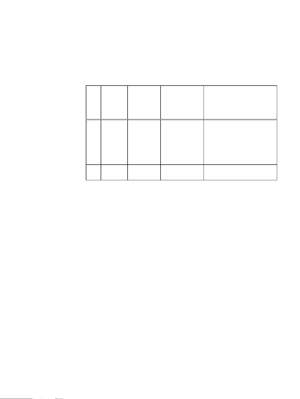
Table 1 Document revision history
Revi
Date Document
sion
part
number/
Revision
number
Software
version
Description
02 January
2017
01 October
2015
302-002-099
REV 02
302-002-099
REV 01
6.0
5.7 Initial publication.
l
Added FRU procedures for the
CMA, the shelf and CMA
bezels, and shelf and CMA rail
kits.
l
Added the disk pack upgrade
procedure.
Revision history 15
Page 16

Revision history
16 EMC Data Domain DS60 Expansion Shelf Installation and FRU Replacement Hardware Guide
Page 17

CHAPTER 1
Technical Specifications
l
Disk drive type.................................................................................................... 18
l
Network cabling..................................................................................................18
l
System operating limits...................................................................................... 18
l
Shipping and storage requirements.................................................................... 19
l
Dimensions and weight....................................................................................... 19
Technical Specifications 17
Page 18
Note
NOTICE
Technical Specifications
Disk drive type
Serial Attached SCSI (SAS) are 12-volt, and support the SAS interface. Firmware and
drive carriers are unique to EMC. Refer to EMC Online Support for a listing of the
supported drives.
Network cabling
Only 3M, 4M and 5M are used with Data Domain shelves.
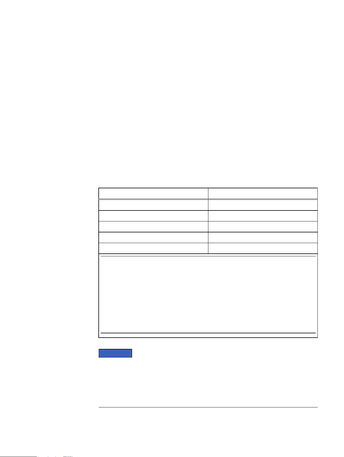
System operating limits
The ambient temperature specification is measured at the front bezel inlet. The site
must have air conditioning of the correct size and placement to maintain the specified
ambient temperature range and offset the heat dissipation listed below.
Table 2 System operating limits
Requirement Description
Ambient temperature 41°F to 104°F (5°C to 40°C)
Temperature gradient 18°F/hr (10°C/hr)
Relative humidity (extremes) 20% to 80% noncondensing
Relative humidity (recommended) 40% to 55% noncondensing
Elevation -50 to 35,000 ft (-16 to 10,600 m)
The allowable relative humidity level is 20 to 80% noncondensing. However, the recommended
operating environment range is 40 to 55%. To minimize the risk of hardware corrosion and
degradation, we recommend lower temperatures and humidity for data centers with gaseous
contamination such as high sulfur content. In general, the humidity fluctuations within the
data center should be minimized. We also recommend that the data center be positively
pressured and have air curtains on entry ways to prevent outside air contaminants and
humidity from entering the facility. For facilities below 40% relative humidity, we recommend
grounding straps when contacting the equipment to avoid the risk of Electrostatic discharge
(ESD), which can harm electronic equipment.
For systems mounted in a cabinet, the operating limits listed above must not be
exceeded inside the closed cabinet. Equipment mounted directly above or below an
shelf must not restrict the front-to-rear airflow of the storage system. Cabinet doors
must not impede the front-to-rear airflow. The cabinet must exhaust air at a rate that
is equal to or greater than the sum of the exhaust rates of all the equipment mounted
in the cabinet.
18 EMC Data Domain DS60 Expansion Shelf Installation and FRU Replacement Hardware Guide
Page 19
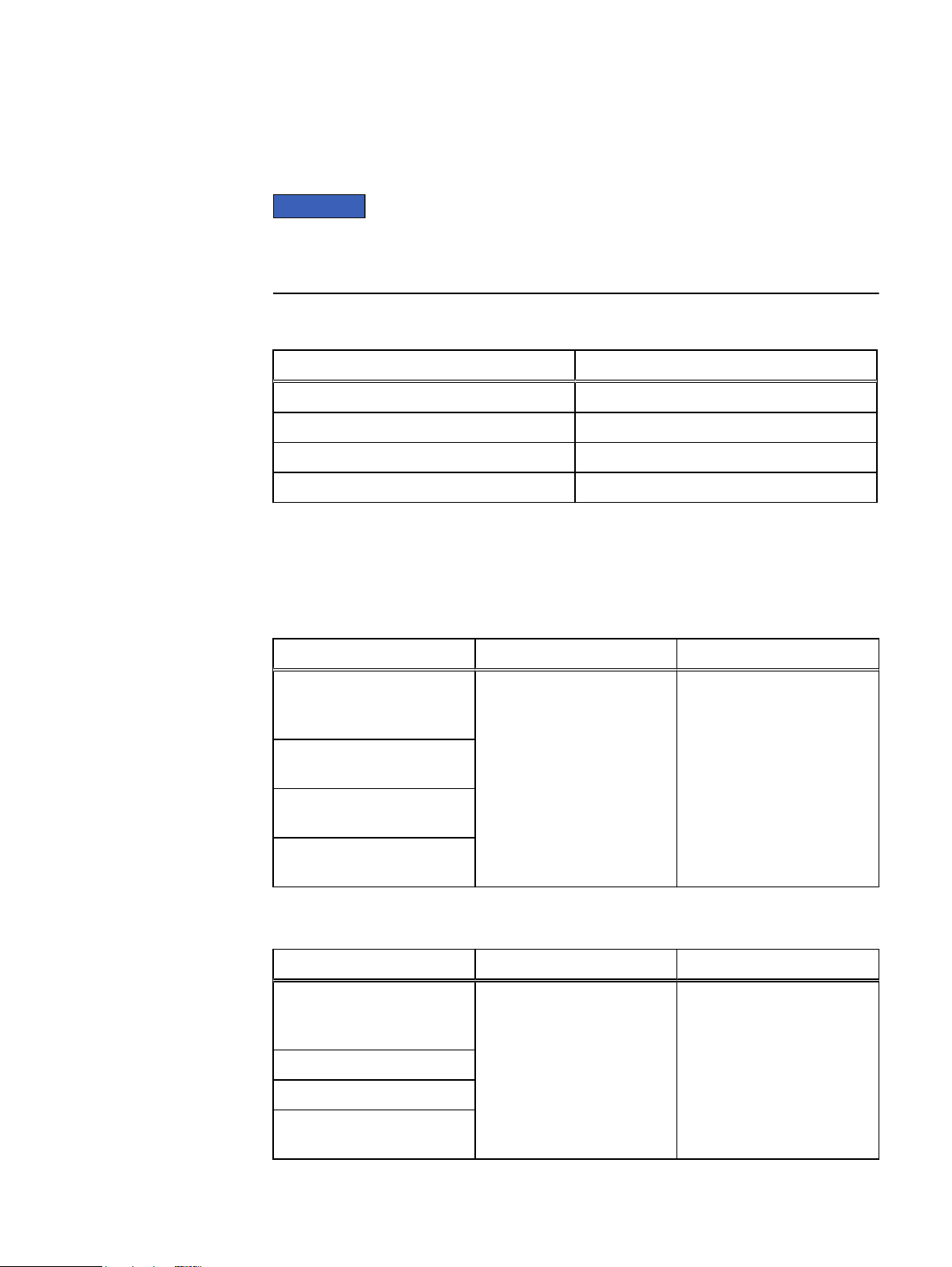
Shipping and storage requirements
NOTICE
Systems and components must not experience changes in temperature and humidity
that are likely to cause condensation to form on or in that system or component. Do
not exceed the shipping and storage temperature gradient of 45°F/hr (25°C/hr).
Table 3 Shipping and storage requirements
Requirement Description
Ambient temperature -40° F to 149°F (-40°C to 65°C)
Temperature gradient 45°F/hr (25°C/hr)
Relative humidity 10% to 90% noncondensing
Elevation -50 to 35,000 ft (-16 to 10,600 m)
Technical Specifications
Dimensions and weight
Table 4
Table 5 Shelf with FRUs installed, dimensions and weight
Shelf with no FRUs installed, dimensions and weight
Dimensions Vertical size Weight
Height: 8.75 in (22.23 cm) 5U
( 4U plus 1U cable
management tray)
Width, including rails: 17.50 in
(44.45 cm)
Depth: Chassis only: 34.5 in
(92.23 cm)
Greatest Feature Depth
36.35in (92.33 cm)
Dimensions Vertical size Weight
Height: 8.75 in (22.23 cm) 5U
( 4U plus 1U cable
management tray)
Standard IEC-310 NEMA 19" 55.0 lb (20.4 kg)
Width: 17.50 in (44.45 cm)
Depth: 34.5 in (92.23cm)
Greatest Feature Depth
36.35in (92.33 cm)
Standard IEC-310 NEMA 19" 225.0 lb (90.7 kg)
Shipping and storage requirements 19
Page 20

Technical Specifications
20 EMC Data Domain DS60 Expansion Shelf Installation and FRU Replacement Hardware Guide
Page 21

CHAPTER 2
Shelf Installation and Removal
l
Shelf installation.................................................................................................22
l
Shelf removal..................................................................................................... 35
l
1U cable management tray installation (underneath)......................................... 52
l
1U cable tray removal.........................................................................................59
l
Non-EMC rack installation................................................................................. 62
l
Removing the universal rails............................................................................... 74
Shelf Installation and Removal 21
Page 22
CAUTION
Shelf Installation and Removal
Shelf installation
This section describes how to install a shelf into a rack.
Installing rails
You should install the rails from the front of the cabinet into which you are installing
the shelf. The 4U includes "inner rails" that slide into the cabinet rail assembly.
Exercise care when installing the short rails. Exposed metal edges may be sharp
and could damage cabling or cause injury to personnel.
Procedure
1. Locate the 4U cabinet space designated for the enclosure.
2. If the rails need to be adjusted, refer to Modifying rail lengths
3. The rails are shipped with M5 adaptors which are designed to fit into the NEMA
channels of an EMC rack. If the rails are being installed in an EMC rack.
Proceed to step 3. If the rails are being installed in a non-EMC rack, proceed as
follows:
a. Using a flat-bladed screwdriver, remove the two M5 adaptors from the
adaptor mounting block on the rails.
b. Identify the correct adaptors needed from the hardware kit and install the
adaptors into the adaptor mounting block. Refer to the following table.
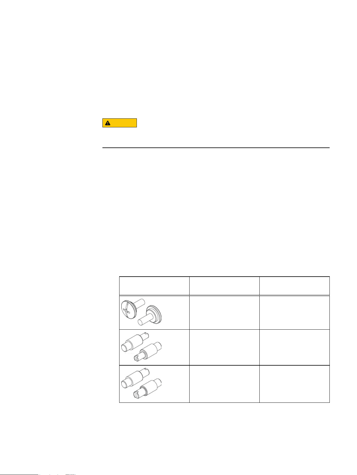
Table 6
Pins for non-EMC racks
Rail Pins from kit Part Number and
Suggested Use
Description
036-028-018
Custom screw, M4 x 10MM
(Quantity: 4 per kit)
036-028-016
3.8MM Alignment Pin
(Quantity: 8 per kit)
036-028-017
4.8MM Alignment Pin
(Quantity: 8 per kit)
Used for any non-EMC
rack. Can be used in racks
with threaded holes.
Used in racks that have
M5, #10, or #12 threaded
holes.
Used in racks that have M6
threaded holes.
22 EMC Data Domain DS60 Expansion Shelf Installation and FRU Replacement Hardware Guide
4. Install the right rail to the rack rear channel. Later sections will detail how to
adjust rails, if necessary.
Page 23
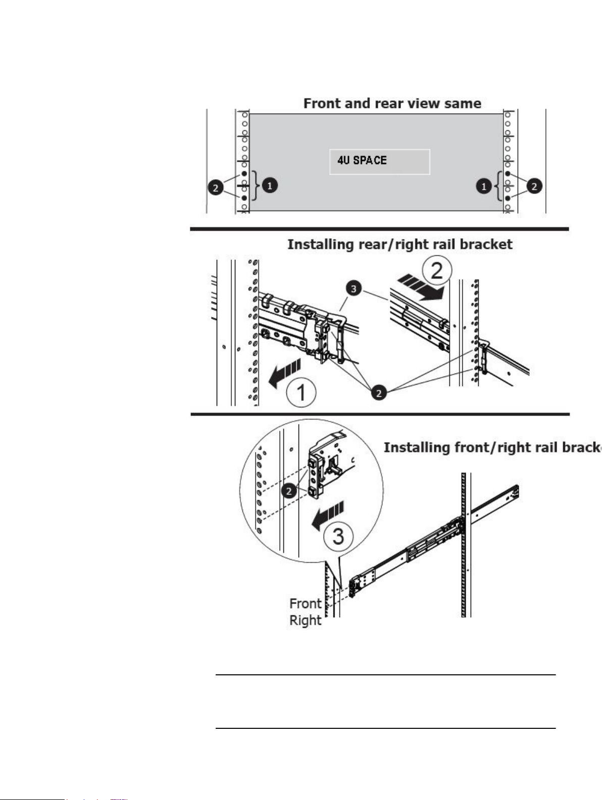
Figure 1 Rail installation
Note
Shelf Installation and Removal
a. Align the right rail with the lower U of the allotted 4U space.
Each of the rail alignment pins must be located in the middle holes of the
bottom two U spaces of the 4U space.
Installing rails 23
Page 24
2
43
CL4868
1
Shelf Installation and Removal
b. With the release latch on the outer (rear) part of the rear channel, place the
catch mechanism over the channel.
c. Push the rail back to secure the rail adaptors in the cabinet channel. An
audible click indicates that the rail is secure in the channel.
d. Make sure the rear post/catch mechanism is secure and attached.
Figure 2 Installing the right rail to the rear channel
5. Install the right rail to the front channel.
a. Align the front of the right rail so that it is level and the front rail pins are
aligned with the middle holes of the bottom two U spaces of the 4U space.
b. Pull the rail forward, with the adaptors aligned with the middle holes of the
bottom two U spaces of the 4U space.
An audible click indicates that the connection is secure.
24 EMC Data Domain DS60 Expansion Shelf Installation and FRU Replacement Hardware Guide
Page 25
Front
Right
CL4866
Note
Shelf Installation and Removal
Figure 3 Installing the right rail to the front channel
6. Install the left rail by repeating step 3 and step 4.
7. On both left and right rail assemblies, install a single long screw between the rail
posts in the upper screw hole to secure the rails as follows:
a. If the rails are being installed in an EMC rack or a rack that does not have
threaded holes, insert a single M5 screw into the larger of the two screw
holes.
b. If the rails are being installed in a non-EMC rack with threaded holes, insert
the M4 screw into the smaller of the two screw holes. The screw will be
smaller than the threaded hole and will pass through the threads.
Working with the portable lift
If a shelf with all of the FRUs removed is being installed, the chassis can be installed
without using the lift. If the shelf is populated with FRUs prior to installing, then this
task requires the use of a portable lift.
The portable lift commonly used by EMC service personnel is manufactured by AlumA-Lift. Instructions for this lift are included in the lift kit. Refer to "http://
www.corkc4.isus.emc.com/wiki/index.php/Lift_Tool". which describes the Lift
equipment, the ordering process, and Links to training material. The Lift Tool Training
Video and Demo on Lift tool using the Voyager assembly (Voyager is the name given
to a Disk enclosure used on many of EMC's product range), are also linked on this
page.
If you are using a portable lift other than the Alum-A-Lift, adapt these instructions as
necessary while following all required safety requirements.
Working with the portable lift 25
Page 26
CAUTION
NOTICE
CL5422
1 2
Shelf Installation and Removal
The portable lift commonly used by EMC service personnel has two
configurations - one with the lower mast only and one with both the lower and
upper masts. The lower mast configuration is rated for 400 pounds and is for
raising or lowering objects 28U (49 inches) or less above the floor. The dual mast
configuration is rated well under 200 pounds and is for raising objects more than
28U (49 inches) above the floor.
l
For installations at or below 49 inches, you must use the lower mast
configuration.
l
For installations above 49 inches, use the "Voyager" conversion kit, rated for
225 pounds, and a support table with the lower mast configuration.
Reconfiguring the lift with Voyager kit
If you are using the Alum-A-Lift for installations or removals above 49 inches (28U),
you must use the single (lower) mast configuration with the "Voyager" conversion kit
and support table.
The "Voyager conversion kit," is used with multiple systems.
Procedure
1. Unpack the Voyager kit.
2. Use the instructions to provided within the kit to reconfigure the lift.
Figure 4
Reconfiguring the portable lift with the Voyager conversion kit
26 EMC Data Domain DS60 Expansion Shelf Installation and FRU Replacement Hardware Guide
Page 27
Adjusting the arms for a frontal lift
1
2
<17”
CL4900
If you plan to use the mechanical lift directly in front of the cabinet, adjust the lift
arm/tray width to just under 17 inches apart to ensure that the arms will stay under
the chassis. Figure 5 on page 27 shows an example of adjusting the lift arm/tray to
just under 17 inches.
Procedure
1. Add the two arms with rollers 17 inches apart measured from the outside edge
of each arm.
2. Tighten the arms to secure them.
Figure 5 Adjusting the lift arm bar to just under 17 inches
Shelf Installation and Removal
Installing the shelf onto the rails
Before you begin
If a shelf with all of the FRUs removed is being installed, the chassis can be installed
without using the lift. If the shelf is populated with FRUs prior to installing, then this
task requires the use of a portable lift.
Adjusting the arms for a frontal lift 27
Page 28
DANGER
CAUTION
Note
Note
CAUTION
Note
Shelf Installation and Removal
DO NOT ATTEMPT to install a populated shelf without a mechanical lift.
Attempting to install a populated shelf without a lift could damage the equipment
and cause injury to personnel
You should only install a shelf into a cabinet if the cabinet is equipped with antitip features.
The following procedure shows an installation using the Alum-a-Lift portable lift. If
another lift is being used, follow the manufacturer's instructions for that lift as
applicable.
A populated shelf requires two people and a lift to install. A de-populated chasses
requires three people to install.
Secure the enclosure to the portable lift using the securing straps before moving
the lift.
Procedure
1. If a portable lift is not available or cannot access the rack, the shelf must be depopulated before it is installed on the rails. Do the following:
a. Refer to the procedures for removing the Power Supplies, LCCs, and Fan
Modules and remove each FRU.
b. Refer to the procedure for removing the disk drives and remove the disk
drives. Label each disk drive as to its exact location so that it can be reinstalled once the chassis is installed in the cabinet.
2. Manually, or using the portable lift (shown below), align the chassis rails with
the inner rails attached to the cabinet. If using a lift, lock the casters into place.
If the chassis is being installed manually without a lift, it generally requires three
people to install. Two people to hold the chassis in place at the correct height,
and one person to align and manage the slides.
3. Manually slide the inner rail over the chassis rail 2-3 inches to line them up.
28 EMC Data Domain DS60 Expansion Shelf Installation and FRU Replacement Hardware Guide
Page 29
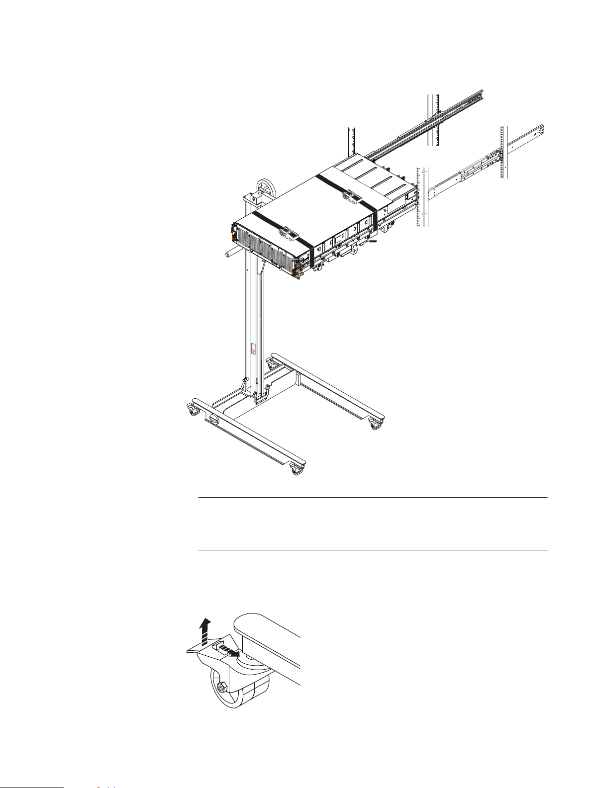
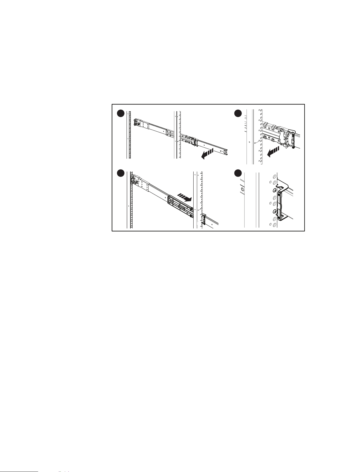
Figure 6 Sliding the shelf chassis into the rails
CL5431
Note
CL5424
Shelf Installation and Removal
You may need to release sagging tension on the shelf by pulling the lift arms and
tray up slightly.
4. Unlock the casters by lifting up on the locking tabs and carefully slide the shelf
into the cabinet as far as the lift will allow.
Figure 7
Unlocking the casters
Installing the shelf onto the rails 29
Page 30
CL5423
1
CL5430
2
CAUTION
Shelf Installation and Removal
5. Release the lift casters
6. Lock all four casters by pressing down on the locking tab so the lift will not roll
as the shelf is pushed into the cabinet.
Figure 8 Locking the casters
7. Remove the securing strap by pulling up on the retaining key and pull the
ratchet handle upwards as needed.
Figure 9 Removing the straps
8. Carefully push the shelf off the lift arms/tray and into the cabinet.
Make sure to leave the lift under the chassis until the shelf is safely
balanced and secured within the cabinet.
9. If the shelf was de-populated prior to installation, re-populate the shelf as
follows:
a. Re-install the disk drives in the exact location from which they were
removed.
b. Re-install the Fan modules.
c. Slide the shelf into the cabinet.
30 EMC Data Domain DS60 Expansion Shelf Installation and FRU Replacement Hardware Guide
Page 31

d. From the rear of the cabinet, re-install the power supplies and the LCCs into
CL4898
21
the shelf.
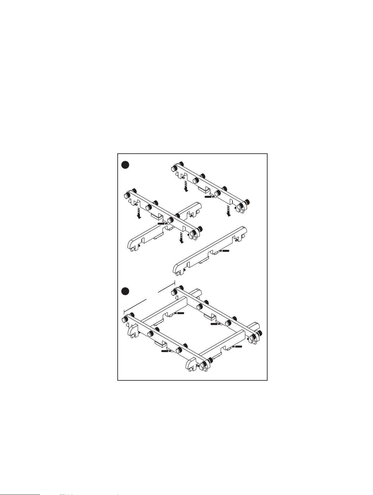
Inserting and securing the top cover and chassis
How the chassis is inserted and secured into the cabinet depends upon which
configuration of securing mechanism is installed on the shelf. The first configuration
has orange self-locking latches above the enclosure latch handles. The second
configuration has captive shoulder screws which attach the chassis to the cabinet.
Procedure
1. If your shelf has the orange self-locking latches above the enclosure latch
handles, proceed as follows:
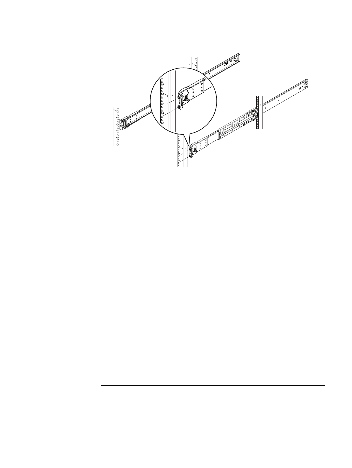
Figure 10 Inserting and securing the chassis to the cabinet
Shelf Installation and Removal
a. Using the orange enclosure latch handles, push the shelf completely into the
cabinet. Make sure the self-locking latches are pushed in and fully engaged,
and the enclosure cannot slide back out of the cabinet.
b. Secure the two knurled black captive screws to the NEMA channel and nut
clips. These screws secure the chassis cover and prevent the cover from
coming out of the cabinet during service.
2. If your shelf has the two-shoulder screw configuration, proceed as follows:
Inserting and securing the top cover and chassis 31
Page 32

Shelf Installation and Removal
Figure 11 Inserting and Securing the Chassis to the Cabinet (Shoulder Screw Configuration)
a. If the shelf is being installed in a non-EMC rack, proceed to substep b. If the
shelf is being installed in an EMC rack, use the orange enclosure latch
handles to push the shelf completely into the cabinet. Align the two semicaptive M5 shoulder screws on each side with the mounting holes on the
cabinet. Thread the shoulder screws into the mounting holes and fingertighten the shoulder screws.
b. To install the shelf into a non-EMC rack (not compatible with the M5
shoulder screws), do the following:
l
Figure 12
Removing semi-captive screws
Remove the semi-captive M5 screws by sliding them from the ears.
l
For non-threaded racks, place tinnernam clips which match the truss head
screws to be used over the mounting holes on the rack. Refer to the table at
the end of this procedure.
32 EMC Data Domain DS60 Expansion Shelf Installation and FRU Replacement Hardware Guide
Page 33

CL5541
3.
Note
Shelf Installation and Removal
l
Figure 13 Installing ears to rack using truss head screws
Use the orange enclosure latch handles to push the shelf completely into the
cabinet. Secure the enclosure to the rack using four truss-head screws.
The top cover can secure to the cabinet in one of two ways, depending upon
your configuration. Some configurations do not have any hardware installed into
the top cover. In these configurations, the appropriate truss head screw must
be used to attach the top cover to the cabinet. Some configurations have semicaptive screws in the top cover that will attach to EMC cabinets. If non-EMC
cabinets are being used, the semi-captive screws can be removed and truss
head screws can be used as required to attach the top cover to the cabinet.
To secure the top cover using a top cover that does not have any mounting
hardware, secure the top cover to the rack using the screws or pins from the kit
that accompanies the device. These screws secure the chassis cover and
prevent the cover from coming out of the cabinet during operation. Secure the
top cover to the rack as follows:
a. If the shelf is being installed into an EMC rack, secure the top cover to the
rack using M5 truss head screws from the kit. Tighten the screws until they
are finger tight.
b. If the shelf is being installed into a non-EMC rack, identify the mounting
holes on the rack that will line up with the mounting holes on the top cover.
Identify which truss head screws will be used to secure the top cover to the
rack (refer to the following table for guidance). For non-threaded racks,
place tinnernam clips over the rack mounting holes. Attach the top cover to
the rack using the appropriate truss head screws from the hardware kit that
comes with the shelf. Refer to the following figure and table for guidance
(shelf and rack not shown).
Inserting and securing the top cover and chassis 33
Page 34

Shelf Installation and Removal
Figure 14 Installing top cover using truss head screws
Table 7 Truss Head Screws
Truss Head Screw from
kit
Part Number and
Description
036-032-010
Screw, M5-0.8x12, Truss
Head Phillips with patch
036-032-011
Screw, M6-1.0x12, Truss
Head Phillips with patch
036-032-009
Screw, 10-32x.5, Truss
Head Phillips with patch
036-032-012
Screw, 12-24x.5, Truss
Head Phillips with patch
Suggested Use
Can be used in EMC racks
and third-party nonthreaded hole racks.
Can be used in non-EMC
racks.
Can be used in non-EMC
racks.
Can be used in non-EMC
racks.
4. To secure the top cover using a top cover with semi-captive screws, do the
following:
a. For an EMC rack, align the semi-captive screws with the mounting hole in
the cabinet and thread the screw into the mounting hole.
5. If a non-EMC rack is being used that is not compatible with the semi-captive
screw, remove the semi-captive screw by pulling the screw assembly out the
side of the top cover. Identify the mounting holes on the rack that will line up
with the mounting holes on the top cover. Identify which truss head screws will
be used to secure the top cover to the rack (refer to the following table for
guidance). For non-threaded racks, place tinnernam clips over the rack
mounting holes. Attach the top cover to the rack using the appropriate truss
head screws from the hardware kit that comes with the shelf.
34 EMC Data Domain DS60 Expansion Shelf Installation and FRU Replacement Hardware Guide
Page 35

Figure 15 Removal of semi-captive screws
CL5545
Note
CAUTION
Shelf removal
This section describes how to remove a shelf from a rack.
Working with the portable lift
If a shelf with all of the FRUs removed is being installed, the chassis can be installed
without using the lift. If the shelf is populated with FRUs prior to installing, then this
task requires the use of a portable lift.
The portable lift commonly used by EMC service personnel is manufactured by AlumA-Lift. Instructions for this lift are included in the lift kit. Refer to "http://
www.corkc4.isus.emc.com/wiki/index.php/Lift_Tool". which describes the Lift
equipment, the ordering process, and Links to training material. The Lift Tool Training
Video and Demo on Lift tool using the Voyager assembly (Voyager is the name given
to a Disk enclosure used on many of EMC's product range), are also linked on this
page.
Shelf Installation and Removal
Planning your lift
If you are using a portable lift other than the Alum-A-Lift, adapt these instructions as
necessary while following all required safety requirements.
The portable lift commonly used by EMC service personnel has two
configurations - one with the lower mast only and one with both the lower and
upper masts. The lower mast configuration is rated for 400 pounds and is for
raising or lowering objects 28U (49 inches) or less above the floor. The dual mast
configuration is rated well under 200 pounds and is for raising objects more than
28U (49 inches) above the floor.
l
For installations at or below 49 inches, you must use the lower mast
configuration.
l
For installations above 49 inches, use the "Voyager" conversion kit, rated for
225 pounds, and a support table with the lower mast configuration.
You can use the lift positioned along the side of the shelf or directly in the front of it.
If possible, position the lift adjacent to the LONG side of the enclosure. This reduces
the front clearance required to 50". Aligning the portable lift perpendicular to the
chassis also reduces the possibility of the chassis sliding off the lift and negates the
requirement to adjust the arm width to approximately 17".
Shelf removal 35
Page 36

CL5431
NOTICE
Shelf Installation and Removal
Table 8 Planning your lift
Lift
position
Side (long) 50" Greater than 18" Best practice, more stable
Front
(short)
Required front
Arm tray width Notes
clearance
60" Between 16-17" Requires arm adjustment, less stable
Refer to: Adjusting the arms for a frontal lift on page 27
Figure 16 Best Practice: Using the portable lift adjacent to the long side of the shelf
Removing the front bezel
You must remove the front bezel to gain access to the internal components. The bezel
is required for EMI compliance when the shelf is powered up. Remove it only to
replace or add an internal component.
36 EMC Data Domain DS60 Expansion Shelf Installation and FRU Replacement Hardware Guide
Page 37

CL4667
DANGER
Shelf Installation and Removal
Procedure
1. If the bezel has a lock, insert the key that shipped with your shelf into the lock,
and turn the key to unlock the bezel.
2. Press the two latch buttons on the bezel surface to release the bezel from the
cabinet.
3. Pull the bezel off the cabinet and put it on a clean, static-free surface.
Figure 17 Removing the front bezel
Pulling the shelf chassis out
Do not extend more than one shelf at a time. Extending more than one shelf at a
time can cause the rack to tip over, which will damage the equipment and may
injure personnel.
To access the internal components, you must release and pull the shelf out of the
cabinet. The shelf slides out of the cabinet far enough for you to access its internal
components and then locks on the rails in the service position so that you cannot pull
it out any farther. The chassis is freed from the cabinet by removing captive shoulder
screws which attach the chassis to the cabinet.
Procedure
1. Unscrew the attaching screws from the NEMA channel.
2. Unscrew the shoulder-screws until they are free from the cabinet. Using the
orange shelf latch handles, pull the slowly pull shelf completely out the cabinet.
Pulling the shelf chassis out 37
Page 38

Note
Shelf Installation and Removal
Figure 18 Pulling the Chassis Out (Two shoulder Screw Configuration)
Removing a shelf from the cabinet
Before you begin
The portable lift commonly used by EMC service personnel is manufactured by AlumA-Lift. Instructions for this lift are included in the lift kit. Refer to "http://
www.corkc4.isus.emc.com/wiki/index.php/Lift_Tool". which describes the Lift
equipment, the ordering process, and Links to training material. The Lift Tool Training
Video and Demo on Lift tool using the Voyager assembly (Voyager is the name given
to a Disk enclosure used on many of EMC's product range), are also linked on this
page.
If you are using a different lift, it must comply with the following requirements:
l
It must be capable of lifting a weight of 225 pounds.
l
It must be used with a rack that has an anti-tipping mechanism installed.
l
It must be capable of reaching the a minimum height of U1 position, and a
maximum height of U29-U31.
You should be able to lower the lift to a minimum height of U1. However, on some
installations you may not be able to install the shelf in the U1 position due to cabling
and other installation considerations.
38 EMC Data Domain DS60 Expansion Shelf Installation and FRU Replacement Hardware Guide
Page 39

Note
<17”
1
2
CL4900
Shelf Installation and Removal
If you plan to use the mechanical lift directly in front of the cabinet, adjust the lift
arm/tray width to just under 17 inches apart to ensure that the arms will stay under
the chassis. The following figure shows an example of adjusting the lift arm/tray to
just under 17 inches. If using a different lift, configure the lift arms and trays according
to the lift manufacturer's instructions.
Figure 19 Example of adjusting the lift arm/tray to just under 17-inches
Procedure
1. Assemble and align the mechanical lift.
2. Configure the lift for at least 225 pounds.
If you are using the Alum-A-Lift, make sure to configure the lift for a 400 pound
rating. Since the dual mast configuration to raise objects more than 28U (49
inches) is rated well under 200 pounds, you cannot use this configuration to
raise or lower a shelf more than 49 inches above the floor. Instead for
installations or removals above 49 inches you must use the single (lower) mast
configuration with the conversion kit and a support table, available from the lift
provider. This kit is rated for 225 pounds.
Removing a shelf from the cabinet 39
Page 40

CAUTION
CL4896
CL4897
Shelf Installation and Removal
The populated shelf can weigh 225 pounds. DO NOT ATTEMPT to lift or
move it without a lift.
3. Disconnect all cables from the rear of the shelf. Label each cable so they can be
re-connected correctly.
4. Refer to the following graphic. Unscrew the two knurled black captive screws
from the NEMA channel.
Figure 20 Releasing chassis from the rails
5. If the two small shipping screws (one per side) are present, remove them as
shown in the following figure.
Figure 21
Removing the shipping screws, if present
6. Unscrew the shoulder-screws until they are free from the cabinet. Using the
orange latch handles, slowly pull the shelf completely out the cabinet. Refer to
the following figure.
40 EMC Data Domain DS60 Expansion Shelf Installation and FRU Replacement Hardware Guide
Page 41

CAUTION
Note
Shelf Installation and Removal
Figure 22 Pulling the chassis out (two shoulder screw configuration)
Do not attempt to remove a populated shelf without a mechanical lift.
If the shelf that you are removing is 28U (49 inches) or more above floor
level, you need to use the conversion and support table kits from Alum-ALift as described in Step 2.
Instructions for the Alum-A-Lift and the conversion kit are included in the lift
kit.
Figure 23 Reconfiguring the Alum-A-Lift with the conversion kit
Removing a shelf from the cabinet 41
Page 42

CL5423
Shelf Installation and Removal
7. To lessen the front-of-cabinet clearance required from a minimum of 60 inches
to slightly more than 50 inches, position the lift on the side of the shelf rather
than directly in front of the shelf if possible.
Aligning the lift perpendicular to the shelf also reduces the possibility of the
shelf sliding off the lift, and negates the need to reduce the arm/tray width
below 18 inches.
8. Raise the lift to the height of the shelf, and lock all four casters by pressing
down on the locking tab so the lift will not roll as the shelf is placed onto it.
Refer to the following figure.
Figure 24 Locking the casters
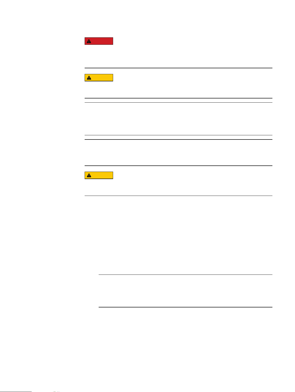
9. With the shelf extended from the rack on the rails, lock the rails in the extended
position. Pull the shelf from the rails and onto the lift. Secure the shelf to the
portable lift using the securing straps as follows:
42 EMC Data Domain DS60 Expansion Shelf Installation and FRU Replacement Hardware Guide
Page 43

CL5431
Shelf Installation and Removal
Figure 25 Removing a shelf from rails more than 49" above the floor
a. Place the securing strap around the lift and the shelf.
b. Insert the free end of the securing strap into the slot on the ratchet
mechanism. Pull the ratchet handle down to tighten the securing strap
around the lift and the shelf.
Removing a shelf from the cabinet 43
Page 44

1 2
CL5429
CL5424
Shelf Installation and Removal
Figure 26 Tightening the straps
Using the lift on a shelf more than 49" above the floor
c. Make sure the shelf is securely strapped to the lift before moving. Once the
shelf is supported by the arm, lower the arm to the lowest point that still
permits travel.
This allows the shelf to be moved with minimal danger of tipping over.
10. Unlock the casters by lifting up on the locking tabs and move the shelf as
required.
Figure 27
Unlocking the casters
If you are using an Alum-A-Lift to work on a shelf that is more than 49 inches above
the floor, you must use the "Voyager" conversion kit and a support table with the
lower mast configuration.
Procedure
1. If necessary, orient the arm to the high-lift position as follows:
44 EMC Data Domain DS60 Expansion Shelf Installation and FRU Replacement Hardware Guide
Page 45

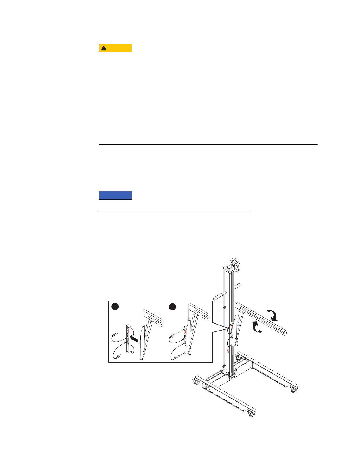
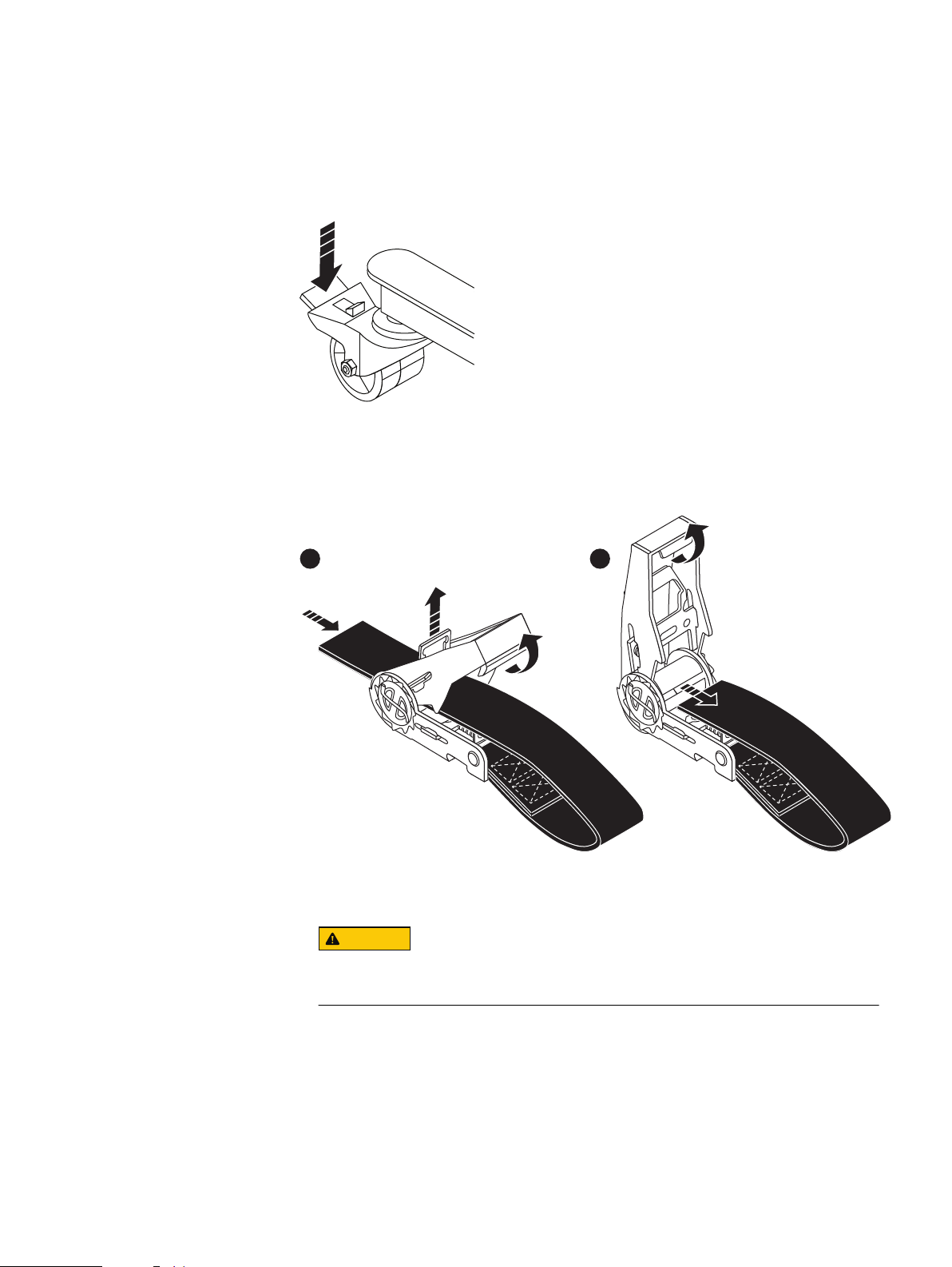
Figure 28 Adjusting the arm for a high rail position
CL5422
1 2
Shelf Installation and Removal
a. Remove the bottom ball lock pin first, by pressing the plunger on the pin and
pulling the pin out. It may be necessary to wiggle the pin with the plunger
pressed to free it from its mounting hole.
b. Hold the arm with one hand while pressing the plunger on the top ball lock
pin and pulling the pin out with the other hand. It may be necessary to wiggle
the pin with the plunger pressed to free it from its mounting hole.
The arm with the adaptor attached will be free of the lift chassis.
c. Remove the arm from the lift and reverse it to achieve the desired
orientation.
d. Attach the arm to the lift chassis by aligning the mounting holes, pressing
the plunger, and inserting the ball lock pins into the holes. Insert the top pin
first.
2. Remove the rotating handle (if necessary) by loosening the set screw and
pulling the handle from the hex fitting.
3. Install and configure the arm trays as required for the lift.
4. Lock all four casters by pressing down on the locking tab so the lift will not roll
as the shelf is placed onto it.
Using the lift on a shelf more than 49" above the floor 45
Page 46

CL5423
CL5431
Shelf Installation and Removal
Figure 29 Locking the Casters
5. Using the cordless drill that comes with the Voyager conversion kit, place the
cordless drill over the hex fitting and use the drill to raise or lower the arm to
the required height. With the node extended from the rack on the rails, pull the
shelf from the rails and onto the lift. Secure the shelf to the portable lift using
the securing straps as follows:
Figure 30 Removing a Shelf from rails more than 49" above the floor
a. Place the securing strap around the lift and the shelf.
46 EMC Data Domain DS60 Expansion Shelf Installation and FRU Replacement Hardware Guide
Page 47

1 2
CL5429
CL5424
Shelf Installation and Removal
b. Insert the free end of the securing strap into the slot on the ratchet
mechanism. Pull the ratchet handle down to tighten the securing strap
around the lift and the shelf.
Figure 31 Tightening the straps
c. Make sure the shelf is securely strapped to the lift before moving. Use the
cordless drill to raise the arm to lift the node from the support table. Once
the shelf is supported by the arm, lower the arm to the lowest point that still
permits travel.
This allows the shelf to be moved with minimal danger of tipping over.
6. Unlock the casters by lifting up on the locking tabs and move the shelf as
required.
Figure 32
Unlocking the casters
7. Move the shelf to the support table. Use the drill to raise or lower the shelf
above the support table. Move the shelf over the support table, and use the drill
to lower the shelf onto the table.
Using the lift on a shelf more than 49" above the floor 47
Page 48

CL5442
1
CL5430
2
Shelf Installation and Removal
Figure 33 Support table
8. Remove the securing strap by pulling up on the retaining key and pull the
ratchet handle upwards as needed.
Figure 34
Removing the straps
9. To move the shelf to the deck or to a shipping pallet, the lift arm must be in the
lower mast position.
Using the Lift on a shelf 49" or less above the floor
You may need to adjust the lift arm position depending on the height of the shelf rails
within the rack or cabinet.
48 EMC Data Domain DS60 Expansion Shelf Installation and FRU Replacement Hardware Guide
Page 49

Procedure
CL5441
1. Orient the arm to the low rail position as follows:
a. Remove the bottom ball lock pin first, by pressing the plunger on the pin and
pulling the pin out. It may be necessary to wiggle the pin with the plunger
pressed to free it from its mounting hole.
b. Hold the arm with one hand while pressing the plunger on the top ball lock
pin and pulling the pin out with the other hand. It may be necessary to wiggle
the pin with the plunger pressed to free it from its mounting hole.
The arm will be free of the lift chassis.
c. Remove the arm from the lift and reverse it to achieve the desired
orientation. The adaptor will be attached to the arm. Do not remove the
adaptor plate.
d. Attach the arm to the lift chassis by aligning the mounting holes, pressing
the plunger, and inserting the ball lock pins into the holes. Insert the top pin
first.
Figure 35 Adjusting the arm for a low rail position
Shelf Installation and Removal
2. Remove the rotating handle by loosening the set screw and pulling the handle
from the hex fitting.
3. Using the cordless drill that comes with the Voyager conversion kit, place the
cordless drill over the hex fitting and use the drill to raise or lower the arm to
the required height.
4. Adjust the arm of the portable lift to the approximate height of the shelf you
intend to move.
5. Attach the tray to the lift arm.
6. Lock all four casters by pressing down on the locking tab so the lift will not roll
as the shelf is placed onto it.
Using the Lift on a shelf 49" or less above the floor 49
Page 50

CL5423
CL5432
Shelf Installation and Removal
Figure 36 Locking the casters
7. Pull the shelf onto the lift (, and then secure the shelf to the portable lift using
the securing straps as follows:
Figure 37 Removing a shelf from rails 49" or less above the floor
a. Place the strap around the lift and the shelf.
b. Insert the free end of the securing strap into the slot on the ratchet
mechanism. Pull the ratchet handle down to tighten the securing strap
around the lift and the shelf.
50 EMC Data Domain DS60 Expansion Shelf Installation and FRU Replacement Hardware Guide
Page 51

Figure 38 Tightening the straps
1 2
CL5429
CL5424
Shelf Installation and Removal
c. Make sure the shelf is securely strapped to the lift before moving. Lower the
lift to its lowest point of travel.
This allows the shelf to be moved with minimal danger of tipping over.
8. Unlock the casters by lifting up on the locking tabs and move the shelf as
required.
Figure 39
Unlocking the casters
9. Remove the securing strap by pulling up on the retaining key and pull the
ratchet handle upwards as needed.
Using the Lift on a shelf 49" or less above the floor 51
Page 52

1
CL5430
2
CL5521
CL5519
Shelf Installation and Removal
Figure 40 Removing the straps
1U cable management tray installation (underneath)
This section describes how to install the 1U cable management tray.
Racks and rails
You can secure the 1U cable tray to EMC and non-EMC racks with a sliding rail
system.
The rail kits are included in the cable tray packaging and are compatible with racks
with the following types of holes:
l
3/8 inch square holes
l
9/32 inch round holes
l
10-32, 12-24, M5X.8, or M6X1 pre-threaded holes
The following table shows the hardware and the recommended rack types:
Hardware from kit
Part Number and
Description
036-034-012
Custom Male-Female 8-32 x .
75 screw
Recommended Rack
Type
Always used to secure rails,
regardless of Rack Type
036-034-003
Custom square hole pin
52 EMC Data Domain DS60 Expansion Shelf Installation and FRU Replacement Hardware Guide
These replace the adaptors
that come pre-installed in the
rails. Used in racks that have .
375" square hole mounting
rails.
Page 53

CL5520
Note
CL5504
Note
Shelf Installation and Removal
Hardware from kit Part Number and
Rail kit mounting brackets adjust in length from 24 inches to 32 inches to
accommodate different rack depths.
Installing the 1U cable management tray
This procedure details how to install the 1U cable management tray.
The underneath configuration utilizes the 1U space beneath the shelf. It is important
when installing the cables, that the correct cable length, cable loops, and pigtail
lengths are carefully considered. Consult the application guide for the product you are
installing to help determine cable lengths. For ease of installation, install the Cable
Management Tray prior to installing the main chassis.
The following procedure describes the installation of the 1U Cable Management Tray
into a standard EMC rack. If a non-EMC rack is being used, use the additional
hardware that comes with the 1U Cable Management Arm to install the rails as
necessary.
Description
036-034-004
Custom threaded hole pin
Recommended Rack
Type
These replace the adaptors
that come pre-installed in the
rails. Used in racks that have
threaded holes. These go into
the threaded hole for support.
Figure 41 Blue tab on rail must be pushed in
Before installing the 1U Cable Management Tray, make sure the blue tab on the shelf
rail (directly above where the 1U Cable Management Tray rails will be installed) is
pressed in.
Installing the 1U cable management tray 53
Page 54

CL5495
CL5518
Shelf Installation and Removal
Procedure
1. Identify the left and right rails. Orient the rails so that the UP arrow is pointed in
the correct direction and so that the end of the rails labeled FRONT is at the
front of the rack.
Figure 42 Installing/Securing rails - front
Figure 43 Installing/Securing rails - rear
2. The rails come pre-assembled with adaptors that fit into standard round
mounting holes. If the rack has a different configuration, use the adaptors in the
hardware kit that come with the tray to mount the rails. Align the flanges on the
inside of the mounting holes of the rack. The rails are adjustable to fit the size
rack you are using. Adjust the rails to the correct size and insert the two
adaptors on the rail into the mounting holes, in both the front and the rear of
the rails. Secure the rails to the rack using two knurled screws from the
hardware package, one in the front of the rail, and one in the rear of the rail. If a
torque screwdriver is available, torque the screws to 12-16 inch-pounds. Repeat
for the other rail.
54 EMC Data Domain DS60 Expansion Shelf Installation and FRU Replacement Hardware Guide
Page 55

CL5523
Shelf Installation and Removal
Figure 44 Installing tray
3. Orient the tray so that the UP arrow is pointed in the correct direction and so
that the end of the tray labeled FRONT is to the front of the rack. Slide the tray
into the rails until it locks into place (audible click). To release the tray, press
the spring clips up and pull the tray towards the front of the rack.
Figure 45
Figure 46 Opening the cable chain lids
Spring Clips - push up to release tray
4. Unclip and open the all of the lids on the cable chains.
Installing the 1U cable management tray 55
Page 56

CL5505
CL5522
Shelf Installation and Removal
Figure 47 Cable positioning in cable chains
5. Refer to the application guide for the shelf you are installing. Using the 1-inch
graduations on the back edge of the tray, route the cables through the cable
chains ( to their suggested lengths, keeping in mind the correct pig-tail lengths.
The two outside cable runs connect to the rack, while the two inside cable runs
connect to the shelf. Once the cables are installed, close the lids, making sure
they are snapped shut.
Figure 48
1-Inch graduation label
6. Align the lids of the Cable Chains so the lids are facing up and the hinges are all
facing each other. Arrange the two cable chains so that they form a "U" shape.
56 EMC Data Domain DS60 Expansion Shelf Installation and FRU Replacement Hardware Guide
Page 57

CL5500
Shelf Installation and Removal
Figure 49 Attaching cable chains to tray
7. Attach the Cable Chains to the tray, by attaching the clips onto the tabs on the
rear of the tray.
Figure 50 Installing the chassis bracket into the shelf
8. Snap the chassis bracket clips into the brackets on the side of the chassis.
Installing the 1U cable management tray 57
Page 58

CL5499
Shelf Installation and Removal
Figure 51 Installing the chassis bracket
9. Place the chassis bracket over the center rail of the cable tray. Clip the free end
of the cable chains to the center flange on the chassis bracket.
Figure 52
Installing the bezel
10. Place the bezel over the front of the tray by pressing the release buttons on the
bezel and placing it over the retaining slots on the tray. Release the buttons and
the tabs will mate with the slots.
11. Refer to the application guide and connect the cables as required. Dress the
cable runs with proper cable strain reliefs when routing to the rack.
58 EMC Data Domain DS60 Expansion Shelf Installation and FRU Replacement Hardware Guide
Page 59

CL5551
Shelf Installation and Removal
Disconnecting cables for an shelf installed with the 1U cable management tray
When servicing an shelf installed with the 1U cable management tray, cables may need
to be disconnected to perform servicing procedures. Follow this procedure when
disconnecting cables on an shelf installed with the 1U cable management tray
Procedure
1. Unplug/disconnect all cables from the rear of the shelf to be serviced.
2. Disconnect the cable guide clips from the chassis.
3. Disconnect the cable guide clips from the 1U cable management tray.
4. Move the cables out of the way to provide access for servicing the shelf.
1U cable tray removal
This section describes how to remove the 1U cable tray.
Removing the 1U cable tray
This procedure describes how to remove the 1U cable tray.
Before you begin
Make sure to retain any hardware that is removed as part of the removal procedure.
This hardware will have to be re-used if the 1U cable tray is re-installed.
Procedure
1. Disconnect all cables from the rear of the shelf.
Figure 53
Remove the bezel
2. At the front of the rack, press the release buttons on the front bezel and
remove it from the tray.
Disconnecting cables for an shelf installed with the 1U cable management tray 59
Page 60

CL5547
CL5548
Shelf Installation and Removal
Figure 54 Remove chassis bracket from chassis
3. Press the tabs on the chassis bracket and remove it from the brackets on the
sides of the chassis.
4. Press the tabs and unclip the cable chains from the chassis bracket.
Figure 55
Remove the chassis bracket
5. Remove the chassis bracket.
60 EMC Data Domain DS60 Expansion Shelf Installation and FRU Replacement Hardware Guide
Page 61

CL5500
CL5523
Shelf Installation and Removal
Figure 56 Unclip the cable chains from the tray
6. Press the tabs and unclip the cable chains from the tray.
7. Unclip the cable chain baskets and remove the cables from the cable chains.
Remove the cable chains.
8. Re-insert the shelf into the rack.
Figure 57
Push spring clips up to release the tray
Removing the 1U cable tray 61
Page 62

CL5549
Shelf Installation and Removal
Figure 58 Remove the tray
9. At the front of the tray, push up on the spring clips and pull the tray towards
the front of the rack until it is free from the rails.
10. Remove the knurled screws from the front and back of the rails.
11. Pull back on the rails until the adaptors clear the front of the rack holes.
Remove the rails.
Non-EMC rack installation
Follow these best practice guidelines to ensure a more orderly installation:
l
Non-EMC racks may have PDUs which face into the rack. This may cause
interference between the shelf and/or rear CMAs (if used). Carefully plan and
route cables to minimize any interference. It may be necessary to use a different
type of PDU that is mounted in the main rack area.
l
The shelf rails have four adjustment ranges, 18-22", 22-26", 26-30", 30-34". The
default length (out of the shipping crate) is the 22-26" setting.
l
After installation, check each rail to ensure that it is level and in the correct
location before installing the next rail.
l
When securing rails to the NEMA channel, especially channels with square holes,
install the screws loosely to prevent cross threading, and tighten by hand. Do not
over torque.
l
Use black M5 screws, which align with both round and square channel holes, to
secure all rails and components in the customer racks. Discard all silver screws
removed from the shipping rack.
Shelf rail installation in non-EMC racks
Shelf rails require 4Us of contiguous space. The same kit, PN 106-569-209, is used for
all drive configurations.
62 EMC Data Domain DS60 Expansion Shelf Installation and FRU Replacement Hardware Guide
Page 63

Table 9 Shelf rail kit contents
CL5496
For... Use kit: ××Kit contents include:
Part number Description
Shelf Installation and Removal
Shelf with any
Disk
Configuration
DENSE DPE FIELD KIT, PN
106-569-209
PN 100-569-001 Rails (pair) and attaching
Modifying rail lengths
This procedure details how to extend or shorten the rail lengths to accommodate
third-party racks.
The rails have four adjustment ranges, 18-22", 22-26", 26-30", 30-34" . The default
length (out of the shipping crate) is the 22-26" setting. The length adjustments
provided in this procedure use the default length as a baseline.
Table 10 Required Tools
Tool Size/Type
Screwdriver Phillips (Cross-tip)
Socket or Wrench (Pliers or Vise-grips may also be
used)
Procedure
10 mm
hardware. Attaching hardware is
detailed in the rail installation
procedure.
1. To change the length of the rail to 18-22" (shortest setting) do the following:
Figure 59
Screw and nut placements
Shelf rail installation in non-EMC racks 63
Page 64

CL5501
Shelf Installation and Removal
a. Orient one of the rails to identify the front of the rail so that the inside of the
rail is visible with the spacing markings visible.
b. Locate the two screws and nuts which hold the length adjustment bracket in
place.
c. Using a screwdriver and a nut driver (pliers or vise-grips will work as well),
remove both screws and nuts. The length adjustment bracket will be free of
the rail.
d. Move to the front of the rail and align the mounting slots with the mounting
holes near the front of the rail.
Figure 60 18"-22" marking
e. . Slide the inner rail mechanism to the front of the rail until the 18"-22" mark
is visible. If the inner mechanism is locked, depress the leaf spring and press
the rail locking mechanism to free it.
f. Adjust the hardware to make sure the mounting holes are aligned with the
mounting slots.
g. Secure the length adjustment bracket in place using both screws and nuts
that were removed earlier.
h. Repeat for the other rail.
2. To change the length of the rail to 26-30", do the following:
a. Orient one of the rails to identify the front of the rail so that the inside of the
rail is visible with the spacing markings visible.
b. Locate the most forward (closest to the front of the rail) screw and nut
which hold the length adjustment bracket in place.
c. Using a screwdriver and a nut driver (pliers or vise-grips will work as well),
remove the forward-most screw and nut.
d. Slide the length adjustment bracket to the rear of the rail until it stops.
64 EMC Data Domain DS60 Expansion Shelf Installation and FRU Replacement Hardware Guide
Page 65

CL5502
CL5503
Shelf Installation and Removal
Figure 61 26"-30" Marking
e. Slide the inner rail mechanism to the rear of the rail until the 26"-30" mark is
visible. If the inner mechanism is locked, depress the leaf spring to free it.
f. Adjust the hardware to make sure the mounting holes are aligned with the
mounting slots.
g. Secure the length adjustment bracket in place using the screw and nut that
were removed earlier.
h. Repeat for the other rail.
3. To change the length of the rail to 30-34"" (longest setting) do the following:
a. Orient one of the rails to identify the front of the rail so that the inside of the
rail is visible with the spacing markings visible.
b. Locate the two screws and nuts which hold the length adjustment bracket in
place.
c. Using a screwdriver and a nut driver (pliers or vise-grips will work as well),
remove both screws and nuts. The length adjustment bracket will be free of
the rail.
d. Move the length adjustment bracket to the rear of the rail and align the
mounting slots with the mounting holes near the rear of the rail.
Figure 62
30"-34" Marking
e. Slide the inner rail mechanism to the rear of the rail until the 30-34" mark is
visible. If the inner mechanism is locked, depress the leaf spring to free it.
f. Adjust the hardware to make sure the mounting holes are aligned with the
mounting slots.
g. Secure the length adjustment bracket in place using both screws and nuts
that were removed earlier.
Shelf rail installation in non-EMC racks 65
Page 66

CAUTION
Note
Shelf Installation and Removal
h. Repeat for the other rail.
4. Once the rails are adjusted to the proper length, install the rails in the rack.
Installing the rails in a non-EMC rack
Exercise care when installing the short rails. Exposed metal edges may be sharp
and could damage cabling or cause injury to personnel.
For each shelf, install the rails using the table, figure and steps that follow. The rails
are designed to be universal in nature. They are shipped with 6.8mm adaptors that will
fit into any EMC rack. To install the universal rails into a non-EMC rack, the 6.8mm
adaptors must be removed, then replaced with rail pins that will fit the hole-types in
the rack being used. The following table shows the rail pins and their suggested use .
Table 11 Pins for non-EMC racks
Rail Pins from kit Part Number and
Suggested Use
Description
036-028-018
Custom screw, M4 x 10MM
(Quantity: 4 per kit)
036-028-016
3.8MM Alignment Pin
(Quantity: 8 per kit)
036-028-017
4.8MM Alignment Pin
(Quantity: 8 per kit)
Used for any non-EMC rack.
Can be used in racks with
threaded holes.
Used in racks that have M5,
#10, or #12 threaded holes.
Used in racks that have M6
threaded holes.
Each of the rail alignment pins must be located in the middle holes of the bottom two
U spaces of the 4U space.
66 EMC Data Domain DS60 Expansion Shelf Installation and FRU Replacement Hardware Guide
Page 67

Table 12 List of parts used in illustration, shelf rail installation
Image # Description Qty Part number
1 shelf rail location in 4U space n/a n/a
Shelf Installation and Removal
2 Universal Rail Pins (see previous table for
n/a Part of PN 106-569-300 and 106-529-209
details)
3 shelf rails (2 each/kit) for each node 2 PN 106-569-300 and 106-529-209
Shelf rail installation in non-EMC racks 67
Page 68

Shelf Installation and Removal
Figure 63 Rail installation
Procedure
1. The rails are shipped with 6.8mm adaptors which are designed to fit into the
NEMA channels of an EMC rack. To install the rails in a non-EMC rack, the
6.8mm adaptors must be removed and replaced with appropriate hardware from
68 EMC Data Domain DS60 Expansion Shelf Installation and FRU Replacement Hardware Guide
Page 69

L
R
Front
Rear
6
Tape
Shelf Installation and Removal
the kit. Do this as follows:
a. Using a flat-bladed screwdriver, remove the two 6.8mm adaptors from the
adaptor mounting block on the rails.
b. Identify the correct adaptors needed from the hardware kit and install the
adaptors into the adaptor mounting block.
2. Locate the 4U rack space designated for the shelf.
3. Install the right rail to the rear channel.
a. Align the right rail so that the alignment pins are centered on the middle
holes of the bottom two U spaces of the 4U space and then move the
bracket with the alignment pins in their proper location.
b. Push the rail back to secure the rail posts in the cabinet channel.
An audible click indicates that the rail is secure in the channel. Make sure the
rear post/catch mechanism is secure and attached.
4. Install the right rail to the front channel.
a. Align the front of the right rail so that it is level and the front rail pins are
aligned with the middle holes of the bottom two U spaces of the 4U space.
b. Pull the rail forward, with the posts aligned with the middle holes of the
bottom two U spaces of the 4U space.
An audible click indicates that the connection is secure.
5. Install the left rail by mirroring the previous steps.
6. Remove the shipping tape attached to the node rails.
Shelf rail installation in non-EMC racks 69
Page 70

CL5376
Shelf Installation and Removal
7. On both left and right rail assemblies, install a single long screw between the rail
posts in the center screw hole to secure the rails as follows:
Figure 64 Securing a rail with a single screw
a. If the rails are being installed in a rack that has threaded holes, insert an M4
screw into the smaller of the two center screw holes at both the front and
the rear of the rail. The screw is smaller and will pass through the threaded
hole in the NEMA racks.
b. If the rails are being installed in a rack that does not have threaded holes,
insert an M5 screw that comes with the chassis into the larger of the two
center screw holes in the rail at the front and rear of the rack.
Table 13
List of parts used in illustration, location of securing screws and alignment pins
Image # Description Qty Part number
1 Node rail location in 4U
space
2 Node rail square alignment
pins
4 M5 or M4 securing screws 4 PN 106-002-452 or
n/a n/a
n/a Part of PN 100-569-209
036-028-018
70 EMC Data Domain DS60 Expansion Shelf Installation and FRU Replacement Hardware Guide
Page 71

Figure 65 Location of securing screws and alignment pins
CL5552
4U space
Front view
4
2
2
1
4
2
2
1
Shelf Installation and Removal
Shelf rail installation in non-EMC racks 71
Page 72

Shelf Installation and Removal
Installing the nutbars
For each shelf, install the nutbars using the table, figure and steps that follow.
Table 14 List of parts used in nutbar installation illustration
Image # Description Qty Part number
1 Nutbar location in 4U space 1 ea Nutbars: (Left: 051-000-357), (Right:
051-000-356)
2 Rail location in the 4U space n/a N/A
3 Rail bracket alignment pins n/a N/A
4 Nutbar alignment pins n/a Part of PN 051-000-357 and PN 051-000-356
5 Nutbar M5 securing screws, black 4 PN 036-709-013
72 EMC Data Domain DS60 Expansion Shelf Installation and FRU Replacement Hardware Guide
Page 73

Figure 66 Nutbar installation (Left nutbar shown)
Note
Shelf Installation and Removal
The nutbars are not interchangeable. There is a distinct nutbar for the left and right
side. Use part numbers for identification.
Procedure
1. At the front of the rack, align and install the left nutbar (051-000-357) directly
above the rail assembly.
2. Secure the nutbar with two M5 securing screws, one above the top alignment
pin and one below the lower alignment pin.
3. Repeat the previous steps for the right nutbar (051-000-356).
Shelf rail installation in non-EMC racks 73
Page 74

CL5555
21
3 4
Shelf Installation and Removal
Removing the universal rails
This procedure describes how to remove the universal rails from an EMC or non-EMC
rack. This procedure assumes the shelf that was installed in the rails has been
removed.
Figure 67 Removing the universal rails
Procedure
1. Remove the center long screw from the front of the rail (1).
2. At the front of the rail, pull the retaining clip free from the rack channel and pull
the rail from the front of the rack until the adaptors are free from the cabinet
mounting holes (2).
3. At the rear of the rack, remove the center long screw from the rear of the rail
(3).
4. Push in the rear rail retaining clip and pull the rail until the adaptors are free
from the cabinet mounting holes (4). Remove the rail.
5. Repeat for the other rail.
74 EMC Data Domain DS60 Expansion Shelf Installation and FRU Replacement Hardware Guide
Page 75

CHAPTER 3
Removing and Replacing FRUs
l
Common procedures ......................................................................................... 76
l
Power supply replacement................................................................................. 80
l
LCC replacement............................................................................................... 83
l
Disk replacement............................................................................................... 86
l
Fan replacement................................................................................................ 94
l
Chassis removal................................................................................................. 99
l
DS60 bezel replacement...................................................................................128
l
DS60 cable management assembly (CMA) bezel..............................................129
l
DS60 cable management assembly (CMA) replacement.................................. 130
l
DS60 rail replacement.......................................................................................137
l
DS60 cable management assembly (CMA) rail replacement............................. 167
Removing and Replacing FRUs
75
Page 76

Removing and Replacing FRUs
Common procedures
This topic contains procedures which are common to the handling of field replaceable
units (FRU) within a device.
Listing of common procedures
The following are the common procedures which are used for the handling FRUs:
l
Avoiding electro-static discharge (ESD) damage
l
Emergency procedures without an ESD kit
l
Hardware acclimation times
l
Identifying faulty parts
Avoiding electrostatic discharge (ESD) damage
When replacing or installing hardware units, you can inadvertently damage the
sensitive electronic circuits in the equipment by simply touching them. Electrostatic
charge that has accumulated on your body discharges through the circuits. If the air in
the work area is very dry, running a humidifier in the work area will help decrease the
risk of ESD damage. Follow the procedures below to prevent damage to the
equipment.
Be aware of the following requirements:
l
Provide enough room to work on the equipment.
l
Clear the work site of any unnecessary materials or materials that naturally build
up electrostatic charge, such as foam packaging, foam cups, cellophane wrappers,
and similar items.
l
Do not remove replacement or upgrade units from their antistatic packaging until
you are ready to install them.
l
Before you begin service, gather together the ESD kit and all other materials you
will need.
l
Once servicing begins, avoid moving away from the work site; otherwise, you may
build up an electrostatic charge.
l
Use ESD anti-static gloves or an ESD wristband (with strap).
If using an ESD wristband with a strap:
n
Attach the clip of the ESD wristband to the ESD bracket or bare metal on a
cabinet/rack or enclosure.
n
Wrap the ESD wristband around your wrist with the metal button against your
skin.
n
If a tester is available, test the wristband.
l
If an emergency arises and the ESD kit is not available, follow the procedures in
Emergency Procedures (without an ESD kit).
Emergency procedures (without an ESD kit)
In an emergency when an ESD kit is not available, use the following procedures to
reduce the possibility of an electrostatic discharge by ensuring that your body and the
subassembly are at the same electrostatic potential.
76 EMC Data Domain DS60 Expansion Shelf Installation and FRU Replacement Hardware Guide
Page 77

NOTICE
These procedures are not a substitute for the use of an ESD kit. Follow them only in
the event of an emergency.
l
Before touching any unit, touch a bare (unpainted) metal surface of the cabinet/
rack or enclosure.
l
Before removing any unit from its antistatic bag, place one hand firmly on a bare
metal surface of the cabinet/rack or enclosure, and at the same time, pick up the
unit while it is still sealed in the antistatic bag. Once you have done this, do not
move around the room or touch other furnishings, personnel, or surfaces until you
have installed the unit.
l
When you remove a unit from the antistatic bag, avoid touching any electronic
components and circuits on it.
l
If you must move around the room or touch other surfaces before installing a unit,
first place the unit back in the antistatic bag. When you are ready again to install
the unit, repeat these procedures.
Hardware acclimation times
Removing and Replacing FRUs
Systems and components must acclimate to the operating environment before
applying power. This requires the unpackaged system or component to reside in the
operating environment for up to 16 hours in order to thermally stabilize and prevent
condensation.
Table 15
Hardware acclimation times (systems and components)
…then let the system
or component
If the last 24 hours of the
TRANSIT/STORAGE
environment was this:
Temperature Humidity
Nominal
68-72°F
(20-22°C)
Cold
<68°F (20°C)
Cold
<68°F (20°C)
Hot
>72°F (22°C)
Nominal
40-55% RH
Dry
<30% RH
Damp
≥30% RH
Dry
<30% RH
…and the OPERATING
environment is this:
Nominal 68-72°F (20-22°C)
40-55% RH
<86°F (30°C) 4 hours
<86°F (30°C) 4 hours
<86°F (30°C) 4 hours
acclimate in the new
environment this many
hours:
0-1 hour
Hot
>72°F (22°C)
Humid
30-45% RH
Humid
45-60% RH
Humid
≥60% RH
<86°F (30°C) 4 hours
<86°F (30°C) 8 hours
<86°F (30°C) 16 hours
Hardware acclimation times 77
Page 78

NOTICE
CAUTION
NOTICE
Removing and Replacing FRUs
Table 15 Hardware acclimation times (systems and components) (continued)
…then let the system
or component
If the last 24 hours of the
TRANSIT/STORAGE
environment was this:
Unknown <86°F (30°C) 16 hours
l
If there are signs of condensation after the recommended acclimation time has
…and the OPERATING
environment is this:
acclimate in the new
environment this many
hours:
passed, allow an additional eight (8) hours to stabilize.
l
Systems and components must not experience changes in temperature and
humidity that are likely to cause condensation to form on or in that system or
component. Do not exceed the shipping and storage temperature gradient of
45°F/hr (25°C/hr).
Removing, installing, or storing replaceable units
Use the following precautions when removing, handling, or storing replaceable units:
Some replaceable units have the majority of their weight in the rear of the
component. Ensure that the back end of the replaceable unit is supported while
installing or removing it. Dropping a replaceable unit could result in personal
injury or damage to the equipment.
l
For a module that must be installed into a slot in an enclosure, examine the rear
connectors on the module for any damage before attempting its installation.
l
A sudden jar, drop, or even a moderate vibration can permanently damage some
sensitive replaceable units.
l
Do not remove a faulted replaceable unit until you have the replacement available.
l
When handling replaceable units, avoid electrostatic discharge (ESD) by wearing
ESD anti-static gloves or an ESD wristband with a strap. For additional
information, refer to Avoiding electrostatic discharge (ESD) damage on page 76.
l
Avoid touching any exposed electronic components and circuits on the replaceable
unit.
l
Never use excessive force to remove or install a replaceable unit. Take time to
read the instructions carefully.
l
Store a replaceable unit in the antistatic bag and the specially designed shipping
container in which you received it. Use the antistatic bag and special shipping
container when you need to return the replaceable unit.
l
Replaceable units must acclimate to the operating environment before applying
power. This requires the unpackaged component to reside in the operating
78 EMC Data Domain DS60 Expansion Shelf Installation and FRU Replacement Hardware Guide
Page 79

NOTICE
Unpacking a part
Note
Note
Removing and Replacing FRUs
environment for up to 16 hours in order to thermally stabilize and prevent
condensation. Refer to Hardware acclimation times on page 77 to ensure the
replaceable unit has thermally stabilized to the operating environment.
Your storage system is designed to be powered on continuously. Most components
are hot swappable; that is, you can replace or install these components while the
storage system is running. However, the system requires that:
l
Front bezels should always be attached to ensure EMI compliance. Make sure you
reattach the bezel after replacing a component.
l
Each slot should contain a component or filler panel to ensure proper air flow
throughout the system.
Procedure
1. Wear ESD gloves or attach an ESD wristband to your wrist and the enclosure in
which you are installing the part.
2. Unpack the part and place it on a static-free surface.
3. If the part is a replacement for a faulted part, save the packing material to
return the faulted part.
Standard touch point colors
Touch points are component locations where you can:
l
grip the hardware to remove or install a component.
l
open or close a latch.
l
Turn a knob to open, close, or adjust a component.
Standard touch point colors are terra-cotta (orange) or blue.
Within this documentation, the color orange is used instead of terra-cotta for
simplicity.
Table 16 Standard touch point colors
Touch point color Description
Terra-cotta
(orange)
This color indicates that you can perform the task, such as remove a
component with a terra-cotta (orange) lever, while the system remains
powered (up/on).
Some tasks may require additional steps.
Unpacking a part 79
Page 80

Note
Removing and Replacing FRUs
Table 16 Standard touch point colors (continued)
Touch point color Description
Blue This color indicates that a shutdown of the system or component is
required before you can perform the task, such as removing a
component with a blue lever.
Power supply replacement
This procedure describes how to remove and a replace a power supply.
Identify the failed power supply unit
Procedure
1. Check the service LED on the affected power supply unit.
If a power supply unit is found to be faulted, the service required LED is a solid
amber.
2. Log in as sysadmin.
3. Enter the alerts show current command to display messages indicating
power supply failure. A sample output is shown.
# alerts show current
Id Post Time Severity Class Object Message
-- ---------------------- -------- ------- --------- ----------81 Mon Jun 1 9:46:27 2015 CRITICAL HWFailure Encl=4:Module=B EVT-ENVIRONMENT-00003:
Power supply module B
is either faulty or
unpowered.
4. Enter the enclosure show powersupply command to check the status of
each power supply.
# enclosure show powersupply
This command may take up to a minute to complete. Please wait...
Enclosure Description Status
--------- --------------------- ----- 4 Power module A pack 1 OK
4 Power module A pack 2 OK
4 Power module A pack 3 OK
4 Power module A pack 4 OK
4 Power module B pack 1 FAILED
4 Power module B pack 2 FAILED
4 Power module B pack 3 FAILED
4 Power module B pack 4 FAILED
--------- --------------------- ------
80 EMC Data Domain DS60 Expansion Shelf Installation and FRU Replacement Hardware Guide
Page 81

Removing a power supply unit
There are two power supply units (PSU) located at the rear of the chassis. The
following procedure can be used to remove either one of them.
Before you begin
Attach an ESD wristband to your wrist and the enclosure with the PSU you are
removing.
Procedure
1. If the shelf is installed with rear cable management arms (CMAs), open the
CMAs.
2. Disconnect the power cables from the PSU.
Removing and Replacing FRUs
3. Refer to the previous figure. Release the PSU by turning the torque-limiting
screw handle counter-clockwise. Unscrewing the torque-limiting screw unseats
the PSU and draws it from the chassis.
4. Pull the PSU straight out from the chassis and place it on a clean, static-free
surface.
Replacing a power supply.
There are two Power Supply Units (PSU) located at the rear of the chassis. The
following procedure can be used to replace either one of them.
Before you begin
Attach an ESD wristband to your wrist and the shelf with the PSU you are removing.
Refer to as you perform the following steps:
Removing a power supply unit 81
Page 82

Removing and Replacing FRUs
Procedure
1. Refer to the previous figure. Push the PSU straight into the chassis until it is
seated into the chassis.
2. Fully seat the PSU in the chassis by turning the torque-limiting screw handle
clockwise until a single click is heard.
Turning the torque-limiting screw draws the PSU into the chassis and fully
seats it into the chassis. The single click indicates the PSU is fully seated.
3. Match the labels on the cables with the correct connectors on the PSU.
Connect the power cables to the PSU.
Verify the power supplies
Procedure
1. Enter the enclosure show powersupply command to find the status of all
the power modules.
# enclosure show powersupply
This command may take up to a minute to complete. Please wait...
Enclosure Description Product ID Part No. Serial No. Version Status
--------- ------------------- ------------ -------------- -------------- ------ ----1 Power module A Power Supply 071-000-555-01 AC7E6132316539 na OK
1 Power module B Power Supply 071-000-555-01 AC7E6132316535 na OK
2 Power module A OK
2 Power module B OK
3 Power module A pack 1 OK
3 Power module A pack 2 OK
3 Power module A pack 3 OK
3 Power module A pack 4 OK
3 Power module B pack 1 OK
3 Power module B pack 2 OK
3 Power module B pack 3 OK
3 Power module B pack 4 OK
4 Power module A pack 1 OK
4 Power module A pack 2 OK
4 Power module A pack 3 OK
4 Power module A pack 4 OK
4 Power module B pack 1 OK
4 Power module B pack 2 OK
4 Power module B pack 3 OK
4 Power module B pack 4 OK
--------- --------------------- ------------ -------------- ------------ ------- -----
2. Enter the enclosure show powersupply command and specify a specific
power module. The output for power supply module 11 should be similar to the
following example:
82 EMC Data Domain DS60 Expansion Shelf Installation and FRU Replacement Hardware Guide
Page 83

Complete the procedure
Note
Procedure
1. Return the failed or replaced part(s) to EMC Data Domain. Reuse the packaging
2. Send an autosupport report from the system by entering the autosupport
Removing and Replacing FRUs
# enclosure show powersupply 11
This command may take up to a minute to complete. Please wait...
Enclosure Description Status
--------- --------------------- ----- 4 Power module A pack 1 OK
4 Power module A pack 2 OK
4 Power module A pack 3 OK
4 Power module A pack 4 OK
4 Power module B pack 1 OK
4 Power module B pack 2 OK
4 Power module B pack 3 OK
4 Power module B pack 4 OK
--------- --------------------- ------
from the new part(s) and use the included prepaid waybill for shipping.
Reference the RMA number on the outside of the package.
send command.
LCC replacement
This procedure describes how to remove and replace an LCC.
Identify the failed
Procedure
1. Check the rear of the shelf for the service LED of the affected .
If the needs to be replaced, the service LED is a solid amber.
2. Log in as sysadmin.
3. Enter the alerts show current command to display messages indicating
failure. A sample output is shown.
# alerts show current
Id Post Time Severity Class Object Message
---- ---------------------- -------- ------- --------- ----------------p0-94 Mon Jun 1 9:46:27 2015 WARNING HWFailure Enclosure=9 EVT-MPATH-00006:
Path redundancy is lost.
Enclosure 9 only has
1 active connection path
and the required number is
2.
4. Enter the enclosure show controllers command to find the failed
controller 9:
# enclosure show controllers 9
Encl 9
Model
Capacity 60 Slots
WWN N/A
Serial # APM00151918344
Number of Controllers 1
Complete the procedure 83
Page 84

Removing and Replacing FRUs
Removing an LCC
Controller A
WWN 50060481109D607F
Firmware 1.1.0
Serial # JWXCL150700011
Status Not Installed
HOST port 24.0 Gbps
EXP'N port 48.0 Gbps
This procedure describes how to remove an LCC from the rear of the chassis. There
are two LCCs accessible from the rear of the chassis. This procedure can be used to
remove either assembly.
Before you begin
Attach an ESD wristband to your wrist and the shelf with the LCC you are removing.
Procedure
1. If the shelf is installed using rear cable management arms (CMAs), open the
CMAs.
Replacing an LCC
2. Refer to the previous figure. Disconnect data cables from the LCC. Release the
LCC by turning the torque-limiting screw handle counter-clockwise until
extends from the rear of the chassis by approximately 1/2 inch. Unscrewing the
torque-limiting screw unseats the LCC and draws it from the chassis.
3. Remove and save the black triangular plastic filler plugs for later use.
4. Pull the LCC straight out from the chassis and place it on a clean, static-free
surface.
This procedure describes how to replace an LCC into the rear of the chassis. There
are two LCCs accessible form the rear of the chassis. This procedure can be used to
replace either assembly.
Before you begin
Attach an ESD wristband to your wrist and the shelf with the LCC you are removing.
84 EMC Data Domain DS60 Expansion Shelf Installation and FRU Replacement Hardware Guide
Page 85

Removing and Replacing FRUs
Procedure
1. Refer to the previous figure. Push the LCC straight into the chassis until it is
seated in the chassis.
2. Fully seat the LCC in the chassis by turning the torque-limiting screw handle
clockwise until a single click is heard.
Turning the torque-limiting screw draws the LCC into the chassis and fully seats
it into the chassis. The single click indicates the LCC is fully seated.
Verify the
3. Connect the data cables to the LCC.
4. Insert the black triangular plastic filler plugs in slots 1 and 3 for both the LCCs.
Verify that the new component is recognized by your system and operating correctly.
Procedure
1. Log in as sysadmin
2. Enter the enclosure show controllers command to verify that the
controller is operating correctly:
# enclosure show controllers 9
Encl 9
Model DS60
Capacity 60 Slots
WWN N/A
Serial # APM00152002461
Number of Controllers 2
Controller A
WWN 500604811082407F
Firmware 1.1.0
Serial # JWXCL150500003
Status OK
HOST port 48.0 Gbps
EXP'N port 0.0 Gbps
Controller B
WWN 500604811086317F
Firmware 1.1.0
Serial # JWXCL150500066
Status OK
HOST port 24.0 Gbps
EXP'N port 48.0 Gbps
Verify the 85
Page 86

Note
Note
Removing and Replacing FRUs
The output provides information about both controllers and includes WWN,
firmware version number, serial number, status, and speed of the link on the
host and expansion ports. If a controller is not discovered, the WWN and serial
number fields are blank. Restart the file system.
3. Enter the enclosure show topology command to verify the HBA ports and
connection:
# enclosure show topology
Port enc.ctrl.port enc.ctrl.port enc.ctrl.port enc.ctrl.port
---- - ------------- - ------------- - ------------- - ------------1a
1b
1c
1d
4a
4b > 9.B.H: 9.B.E > 11.B.H:11.B.E
4c
4d
7a
7b
7c
7d
10a
10b > 11.A.H:11.A.E > 9.A.H: 9.A.E
10c
10d
---- - ------------- - ------------- - ------------- - -------------
4. Enter the filesys enable command to restart the file system.
Complete the procedure
Procedure
1. Return the failed or replaced part(s) to EMC Data Domain. Reuse the packaging
2. Send an autosupport report from the system by entering the autosupport
Disk replacement
This procedure describes how to remove and replace a disk.
Identify the failed drive
Procedure
The output provides a text representation of each HBA port and the order in
which the shelf controllers are connected. If the replacement controller does
not appear in the map, then there is still an issue with this controller.
from the new part(s) and use the included prepaid waybill for shipping.
Reference the RMA number on the outside of the package.
send command.
1. Check the disk enclosure LEDs visible on the front panel of the shelf. Use the
table to identify the color and status.
86 EMC Data Domain DS60 Expansion Shelf Installation and FRU Replacement Hardware Guide
Page 87

Note
Note
Removing and Replacing FRUs
The individual disk LEDs are only visible when the disk enclosure is opened to
verify the disks inside.
Table 17 Status lights
Light Quantity Color Meaning
Disk enclosure power 1 Blue Power to enclosure is
on.
Disk enclosure fault 1 Amber On when any fault
condition exists; if the
fault is not obvious
from a disk module
light, look at the back
of the disk enclosure.
Disk active
Only visible after the
disk enclosure is
opened.
1 per disk module Blue No LED when the slot
is empty or has a filler
module. Also, off
when the disk is
powered down by
command; for
example, the result of
a temperature fault.
Fast blinking when
the SAS drive is
powered up but not
spinning; this is a
normal part of the
spin-up sequence,
occurring during the
spin-up delays of a
slot.
On when the drive
has power but is not
handing any I/O
activity (the ready
state).
Disk and fan lights are
only available when
enclosure is removed
from the chassis.
Slow blinking when
the drive is spinning
and handling I/O
activity.
Disk fault
1 per disk module Amber On when the disk
module is faulty, or as
an indication to
replace the drive.
Identify the failed drive 87
Page 88

Note
Note
Note
Removing and Replacing FRUs
Table 17 Status lights (continued)
Light Quantity Color Meaning
Only visible after the
disk enclosure is
opened.
2. To ensure correct identification, use the commands in the next steps.
3. Log in as a sysadmin user.
4. Enter the alerts show current command to display messages indicating
disk drive failure. Sample output for this command is shown:
# alerts show current
Id Post Time Severity Class Object Message
---- ---------------------- -------- ------- --------- ----------------p0-83 Mon Jun 8 8:40:25 2015 CRITICAL HWFailure Enc=4:Disk=3 EVT-STORAGE-00001:
Disk has a hardware
fault and may need
to be replaced.
5. Enter the disk show state command to display the state of all disk drives
and to identify a failed disk. Sample output for this command is shown.
Failed F and absent A are possible values.
# disk show state
|--------|--------|--------|--------|
| Pack 1 | Pack 2 | Pack 3 | Pack 4 |
E(49-60) |. . s |. . s |. . s |. . s |
D(37-48) |. . . |. . . |. . . |. . . |
C(25-36) |. . . |. . . |. . . |. . . |
B(13-24) |. . . |. . . |. . . |. . . |
A( 1-12) |. F . |. . . |. . . |. . . |
|--------|--------|--------|--------|
-------------- ----------------------------------------------
Legend State Count
------ ------------ ----. In Use Disks 59
s Spare Disks 4
F Failed 1
------ ------------ ----Total 64 disks
6.
The disk beacon
enclosure-id.disk-id
command does not generate any
output.
Pull the shelf out of the rack to check for the HDD LED blinking to identify the
faulty disk drive.
88 EMC Data Domain DS60 Expansion Shelf Installation and FRU Replacement Hardware Guide
Page 89

Opening the console
21
CL4699
NOTICE
Removing and Replacing FRUs
The console is a protruding plastic banner on the front of the cabinet with a stripe of
blue or green light and the product badge.
If the console is covering the front of the shelf to which you need access, open the
console using the steps that follow.
Procedure
1. Grasp the right side of the console.
2. Pull the console to swing it open.
Figure 68 Opening the console
Removing the front bezel
You must remove the front bezel to gain access to the internal components. The bezel
is required for EMI compliance when the shelf is powered up. Remove it only to
replace or add an internal component.
Procedure
1. If the bezel has a lock, insert the key that shipped with your shelf into the lock,
and turn the key to unlock the bezel.
2. Press the two latch buttons on the bezel surface to release the bezel from the
cabinet.
3. Pull the bezel off the cabinet and put it on a clean, static-free surface.
Opening the console 89
Page 90

CL4667
DANGER
Removing and Replacing FRUs
Figure 69 Removing the front bezel
Pulling the shelf chassis out
Do not extend more than one shelf at a time. Extending more than one shelf at a
time can cause the rack to tip over, which will damage the equipment and may
injure personnel.
To access the internal components, you must release and pull the shelf out of the
cabinet. The shelf slides out of the cabinet far enough for you to access its internal
components and then locks on the rails in the service position so that you cannot pull
it out any farther. The chassis is freed from the cabinet by removing captive shoulder
screws which attach the chassis to the cabinet.
Procedure
1. Unscrew the attaching screws from the NEMA channel.
2. Unscrew the shoulder-screws until they are free from the cabinet. Using the
orange shelf latch handles, pull the slowly pull shelf completely out the cabinet.
90 EMC Data Domain DS60 Expansion Shelf Installation and FRU Replacement Hardware Guide
Page 91

CAUTION
Note
Removing and Replacing FRUs
Figure 70 Pulling the Chassis Out (Two shoulder Screw Configuration)
Removing a disk drive
This procedure describes how to remove a disk drive from the chassis.
A faulted disk has an amber fault LED on its carrier. However, the amber fault LED
may not always be illuminated if a drive fails. Refer to the troubleshooting procedures
to correctly identify faulted disk drives. Do not replace a faulted disk until you have a
replacement disk with the same part number available.
A disk drive must be replaced within 10 minutes after the shelf is slid out of the
rack. If it is not returned to the rack within 10 minutes, all drives may be powered
down to avoid overheating the node.
Disks can be removed and replaced with the power applied to the shelf.
Procedure
1. Attach an ESD wristband to your wrist and the shelf with the disks you are
removing.
Removing a disk drive 91
Page 92

1
CL5464
2 3
CAUTION
Note
CAUTION
Removing and Replacing FRUs
Figure 71 Removing a disk drive
2. Extend the chassis from the rack.
The disk drives must be placed back into the exact same slot when
replaced. If all of the disk drives are being removed so that the chassis can
be replaced, it is critically important that the location of each drive is
recorded. The disk drives must be placed back into the exact same slot
upon installation into the replacement chassis.
3. Locate the disk drive to be replaced.
4. Refer to the previous figure when removing the disk drive. Push the disk's
orange release tab towards the front of the shelf (1).
5. Lift the disk's latch and slowly pull the disk about 1 in (3 cm) from its slot (2).
6. Do one of the following:
l
If the disk's fault LED is on steadily, pull the disk straight out about 2 inches
(5 centimeters) from its slot, and wait 30 seconds for the disk to stop
spinning before pulling the disk completely out of the slot (3).
l
If the disk's fault LED is off or mostly off, pull the disk completely out of the
slot (3).
Installing a disk
Refer to Installing a disk while you perform the procedure that follows.
Disk drives must be placed into the exact same location from which they were
removed.
A disk drive must be replaced within 10 minutes after the shelf is slid out of the
cabinet.
92 EMC Data Domain DS60 Expansion Shelf Installation and FRU Replacement Hardware Guide
Page 93

Note
CAUTION
CL5465
31 2
Note
Removing and Replacing FRUs
Disks can be removed and replaced with the power applied to the shelf.
Procedure
1. Attach and ESD wristband to your wrist and the shelf in which you are installing
the disk
2.
Do not drop the disk drive into the slot. Dropping the disk drive may
damage the disk drive and the drive interface backplane, which requires a
full chassis replacement.
With the disk carrier latch fully open, align the module with the guides and
gently lower the disk into the slot (1).
The latch begins to rotate downward when its tabs meet the shelf.
3. Push on the latch tab to engage the latch (2).
4. When the latch is engaged, push firmly on the module to verify that the disk is
properly seated (3).
The disk's Active light flashes to reflect the disk's spin-up sequence.
Figure 72
Installing a disk
Verify the operation of the new disk drive
Procedure
1. Rescan all of the disks by entering the disk rescan command
This command does not generate any output. The amount of time it takes to
complete depends on how many disks are attached.
2. After the rescan completes, enter the disk show state command to verify
the state of all drives. This command checks that the drive is recognized.
# disk show state
|--------|--------|--------|--------|
| Pack 1 | Pack 2 | Pack 3 | Pack 4 |
E(49-60) |. . . |. . s |. . s |. . s |
D(37-48) |. . . |. . . |. . . |. . . |
Verify the operation of the new disk drive 93
Page 94

Note
Note
Removing and Replacing FRUs
Installing the front bezel
Procedure
C(25-36) |. . . |. . . |. . . |. . . |
B(13-24) |. . . |. . . |. . . |. . . |
A( 1-12) |. s . |. . . |. . . |. . . |
|--------|--------|--------|--------|
------------- ----------------------------------------------
Legend State Count
------ ------------ ----. In Use Disks 60
s Spare Disks 4
------ ------------ ----Total 64 disks
When the amber fault light has turned off on the front panel of the shelf, all the
disk are in good state.
1. Align the bezel with the shelf.
2. Gently push the bezel into place on the cabinet until it latches.
3. If the bezel has a key lock, lock the bezel the provided key.
Complete the procedure
Procedure
1. Return the failed or replaced part(s) to EMC Data Domain. Reuse the packaging
from the new part(s) and use the included prepaid waybill for shipping.
Reference the RMA number on the outside of the package.
2. Send an autosupport report from the system by entering the autosupport
send command.
Fan replacement
Fan modules are arranged across the front of the open shelf, and numbered 0-2, left
to right. A faulted fan module has an amber fault light. Do not remove a faulted fan
module until you have a replacement module with the same part number available.
Identify the failed fan unit
Procedure
1. Check the enclosure service LED and the service LED on the affected fan.
If a fan is found to be faulted, the enclosure service LED is lit and so is the
service LED on the affected fan. A fan failure is indicated if the fan is missing,
spinning at too low of RPMs, or if it fails the daily full speed fan test.
2. Log in as sysadmin.
94 EMC Data Domain DS60 Expansion Shelf Installation and FRU Replacement Hardware Guide
Page 95

Note
Removing and Replacing FRUs
3. Enter the alerts show current or alerts show current-detailed
command which displays messages indicating fan failure. A sample output is
shown.
# alerts show current
Id Post Time Severity Class Object Message
--- ---------------------- -------- --------- ----------- ----------p0-90 Tue June 2 1:40:07 2015 CRITICAL HWFailure Encl=11:Fan Id=2 EVT-ENV-00004:
Cooling module fan 2
has failed.
4. Enter the enclosure show fans command to check the status of each fan.
Record the failed fan. A sample output is shown. In the output below the Level
column indicates the RPM of the fan as low, medium, and high. The Status
column indicates the status as OK, Unavailable, and Failed.
# enclosure show fans
Enclosure Description Level Status
--------- -------------------- ----- -----11 Cooling module fan 1 low OK
Cooling module fan 2 low FAILED
Cooling module fan 3 low OK
Power module A fan 1 low OK
Power module A fan 2 low OK
Power module B fan 1 low OK
Power module B fan 2 low OK
--------- -------------------- ----- ------
Removing the front bezel
You must remove the shelf’s front bezel to gain access to the internal components.
The bezel is required for EMI compliance when the instrument is powered up. Remove
it only to replace or add disks or fans.
Refer to Figure 17 on page 37 while performing the procedure that follows.
Procedure
1. If the bezel has a lock, insert the key that shipped with your enclosure into the
lock, and turn the key to unlock the bezel.
2. Press the two latch buttons on the bezel surface to release the bezel from the
cabinet.
3. Pull the bezel off the cabinet and put it on a clean, static-free surface.
Figure 73
Removing the front bezel
Removing the front bezel 95
Page 96

DANGER
Removing and Replacing FRUs
Pulling the shelf chassis out
Do not extend more than one shelf at a time. Extending more than one shelf at a
time can cause the rack to tip over, which will damage the equipment and may
injure personnel.
To access the internal components, you must release and pull the shelf out of the
cabinet. The shelf slides out of the cabinet far enough for you to access its internal
components and then locks on the rails in the service position so that you cannot pull
it out any farther. The chassis is freed from the cabinet by removing captive shoulder
screws which attach the chassis to the cabinet.
Procedure
1. Unscrew the attaching screws from the NEMA channel.
2. Unscrew the shoulder-screws until they are free from the cabinet. Using the
orange shelf latch handles, pull the slowly pull shelf completely out the cabinet.
Figure 74 Pulling the Chassis Out (Two shoulder Screw Configuration)
Removing a fan module
Before you begin
Attach an ESD wristband to your wrist and the shelf with the fan module.
96 EMC Data Domain DS60 Expansion Shelf Installation and FRU Replacement Hardware Guide
Page 97

Note
Note
Removing and Replacing FRUs
The shelf must have at least two fan modules installed while the shelf is powered up;
do not remove more than one fan module while AC power is on. There is a five minute
limit to replace a fan before the system may start shutting down the disk drives. Do
not remove a faulted fan unless a replacement is on hand and available to be installed
within five minutes.
Installing a fan
Procedure
1. Refer to the previous figure to perform this procedure. Unlock the fan module
by pushing the orange tab to the left.
2. Pull up on the latch handle to release the fan module.
3. Pull the fan module up and out of the chassis.
Before you begin
The shelf must have at least two fan modules installed while the shelf is powered up;
do not remove more than one fan module while AC power is on. There is a five minute
limit to replace a fan before the system may start shutting down the disk drives. Do
not remove a faulted fan unless a replacement is on hand and available to be installed
within five minutes.
Attach an ESD wristband to your wrist and the shelf where you will install the fan.
Installing a fan 97
Page 98

Removing and Replacing FRUs
Verify the fans
Procedure
1. Refer to the previous figure. Align the fan with the guides for the empty slot,
then insert the it into the slot.
2. Push the latch down into the closed position.
3. Push the black tab above the orange release tab down until you hear a click.
The click indicates that the fan is seated and secure in the slot.
Procedure
1. Enter the enclosure show fans command to check the status of the
replaced fans.
# enclosure show fans 9
Enclosure Description Level Status
--------- -------------------- ----- -----9 Cooling module fan 1 low OK
Cooling module fan 2 low OK
Cooling module fan 3 low OK
Power module A fan 1 low OK
Power module A fan 2 low OK
Power module B fan 1 low OK
Power module B fan 2 low OK
--------- -------------------- ----- ------
Check the Status column to confirm that all of the fans in Enclosure 9 are OK.
2. Enter the alerts show current command and confirm that the system has
cleared the alert for the failed fan. It may take one to two minutes after the fan
replacement before the system clears the alert.
98 EMC Data Domain DS60 Expansion Shelf Installation and FRU Replacement Hardware Guide
Page 99

Installing the front bezel
Note
Procedure
1. Align the bezel with the shelf.
2. Gently push the bezel into place on the cabinet until it latches.
3. If the bezel has a key lock, lock the bezel the provided key.
Complete the procedure
Procedure
1. Return the failed or replaced part(s) to EMC Data Domain. Reuse the packaging
2. Send an autosupport report from the system by entering the autosupport
Removing and Replacing FRUs
# alerts show current
No active alerts.
from the new part(s) and use the included prepaid waybill for shipping.
Reference the RMA number on the outside of the package.
send command.
Chassis removal
This section describes how to remove a fully populated chassis for the purposes of
transferring FRUs to a replacement chassis. Since a fully populated chassis weighs
approximately 225 pounds, the following are required to remove and replace a chassis:
l
l
l
These are needed to do the following:
l
l
l
l
l
When removing the disk drives, each disk drive must be transferred into the
corresponding location in the replacement chassis..
A lift that can support the shelf for both removing and transferring FRUs;
A work surface capable of holding two shelves, side-by-side;
An interim table capable of supporting a fully populated shelf.
If required, reconfigure the lift so it can be moved to its lowest setting to transport
the shelf. this will have to be done if the shelf was removed from a location that
was 49" or higher from the floor;
Remove the shelf from the rack;
Move the shelf to an interim table;
Place the shelf back on the lift, lower it as far as possible, then transport it to the
work location;
Place the shelf side-by-side with the replacement chassis, then the FRUs are
transferred.
Working with the portable lift
If a shelf with all of the FRUs removed is being installed, the chassis can be installed
without using the lift. If the shelf is populated with FRUs prior to installing, then this
task requires the use of a portable lift.
The portable lift commonly used by EMC service personnel is manufactured by AlumA-Lift. Instructions for this lift are included in the lift kit. Refer to "http://
Installing the front bezel 99
Page 100

Note
CAUTION
NOTICE
Removing and Replacing FRUs
www.corkc4.isus.emc.com/wiki/index.php/Lift_Tool". which describes the Lift
equipment, the ordering process, and Links to training material. The Lift Tool Training
Video and Demo on Lift tool using the Voyager assembly (Voyager is the name given
to a Disk enclosure used on many of EMC's product range), are also linked on this
page.
If you are using a portable lift other than the Alum-A-Lift, adapt these instructions as
necessary while following all required safety requirements.
The portable lift commonly used by EMC service personnel has two
configurations - one with the lower mast only and one with both the lower and
upper masts. The lower mast configuration is rated for 400 pounds and is for
raising or lowering objects 28U (49 inches) or less above the floor. The dual mast
configuration is rated well under 200 pounds and is for raising objects more than
28U (49 inches) above the floor.
l
For installations at or below 49 inches, you must use the lower mast
configuration.
l
For installations above 49 inches, use the "Voyager" conversion kit, rated for
225 pounds, and a support table with the lower mast configuration.
Reconfiguring the lift with Voyager kit
If you are using the Alum-A-Lift for installations or removals above 49 inches (28U),
you must use the single (lower) mast configuration with the "Voyager" conversion kit
and support table.
The "Voyager conversion kit," is used with multiple systems.
Procedure
1. Unpack the Voyager kit.
2. Use the instructions to provided within the kit to reconfigure the lift.
100 EMC Data Domain DS60 Expansion Shelf Installation and FRU Replacement Hardware Guide
 Loading...