

EMC Connectrix EC-1200 Planning Manual

Connectrix v6.02
2 Gb/s Enterprise Storage Network System
PLANNING GUIDE
P/N 300-000-691
REV A01
EMC Corporation
171 South Street
Hopkinton, MA 01748-9103
Corporate Headquarters: (508) 435-1000, (800) 424-EMC2
Fax: (508) 435-5374 Service: (800) SVC-4EMC

Copyright © 2001 – 2002 EMC Corporation. All rights reserved.
Printed September 2002
EMC believes the information in this publication is accurate as of its publication date. The information is
subject to change without notice.
THE INFORMATION IN THIS PUBLICATION IS PROVIDED "AS IS." EMC CORPORATION MAKES NO
REPRESENTATIONS OR WARRANTIES OF ANY KIND WITH RESPECT TO THE INFORMATION IN THIS
PUBLICATION, AND SPECIFICALLY DISCLAIMS IMPLIED WARRANTIES OF MERCHANTABILITY OR
FITNESS FOR A PARTICULAR PURPOSE.
Use, copying, and distribution of any EMC software described in this publication requires an applicable
software license.
Trademark Information
ii
Connectrix v6.02 Planning Guide

Contents
Preface............................................................................................................................. xi
Chapter 1 EC-1200 Connectrix Cabinet
EC-1200 Overview........................................................................... 1-2
Features...................................................................................... 1-2
Base Configuration................................................................... 1-2
Connectrix Models ................................................................... 1-3
Guidelines for Installing Directors and Switches .............. 1-11
EC-1100 Cabinet Configurations .......................................... 1-17
Maximum Configuration....................................................... 1-18
Manageability................................................................................. 1-20
Connectrix Service Processor................................................ 1-20
Connectrix Manager............................................................... 1-23
Serviceability Features ........................................................... 1-27
Remote User Workstations.................................................... 1-30
Multi-Home Clients................................................................ 1-30
Chapter 2 Fibre Channel Switching Concepts
Fibre Channel Port Types................................................................ 2-2
Device Discovery ............................................................................. 2-3
Parallel SCSI Versus Fibre Channel........................................ 2-3
The Name Server ...................................................................... 2-3
Fabric Addressing............................................................................ 2-4
Physical Address....................................................................... 2-4
Domain ID Assignment........................................................... 2-5
Principal Switch Selection............................................................... 2-7
Fabric WWN Assignment............................................................... 2-9
E_Port Segmentation ..................................................................... 2-10
Connectrix v6.02 Planning Guide
iii

Contents
Fabric Services and State Change Notifications........................ 2-11
Classes of Service........................................................................... 2-12
Persistent Binding.......................................................................... 2-13
Heterogeneous Server Support.................................................... 2-16
Bandwidth ...................................................................................... 2-17
Path Selection and ISL Loading................................................... 2-21
Shortest Path First................................................................... 2-22
Multiple Equal-Cost Paths .................................................... 2-22
Load Assignment on World Wide Node Names ............... 2-23
Frame Delivery Order................................................................... 2-24
Chapter 3 Zoning and Naming
Zoning ............................................................................................... 3-2
V6.02 Zoning Capabilities....................................................... 3-4
Single-HBA Zoning.................................................................. 3-7
Merging Zoned Fabrics................................................................. 3-10
Rules for Merging Zoned Fabrics......................................... 3-10
Zone Naming — Character Set Considerations........................ 3-12
Connectrix Naming Guidelines................................................... 3-14
Chapter 4 Connectrix Topologies
Microcode Levels............................................................................. 4-2
Physical and Logical Topologies ................................................... 4-3
Base Switch Topologies................................................................... 4-4
Symmetrix Capacity Application........................................... 4-4
Symmetrix Consolidation Application.................................. 4-5
Combined Topologies.............................................................. 4-7
Calculating Fan-in and Fan-out.............................................. 4-7
Multiswitch Topologies................................................................. 4-11
Data Center to Data Center................................................... 4-11
Tape Backbone ........................................................................ 4-15
Many to Many......................................................................... 4-16
Open Fabric 1.0 .............................................................................. 4-19
Connectrix Version 6.02 Topology Solution Envelope ............. 4-20
Connectivity ............................................................................ 4-20
ISL Performance............................................................................. 4-28
Adding Bandwidth........................................................................ 4-29
Chapter 5 Planning Considerations
Configuration Objectives................................................................ 5-2
Planning the Initial Configuration......................................... 5-2
iv
Connectrix v6.02 Planning Guide

Contents
Planning Switch Ports..................................................................... 5-3
Determining the Number of Ports......................................... 5-4
Determining Port Types .......................................................... 5-5
Port Binding.............................................................................. 5-6
Planning for Spare Ports ......................................................... 5-7
Using Multiple Switches......................................................... 5-7
Planning Cabling............................................................................. 5-8
Types of Cable .......................................................................... 5-8
Available Cables ....................................................................... 5-9
Adapters.................................................................................. 5-10
Planning Considerations....................................................... 5-11
Calculating Channel Insertion Loss .................................... 5-13
Arranging Cable Connections.............................................. 5-14
Cable Lengths......................................................................... 5-17
Routing Fiber-Optic Cables.................................................. 5-18
Power Cables .......................................................................... 5-20
Security Considerations ............................................................... 5-21
Connectrix Service Processor ............................................... 5-22
Remote User Workstations ................................................... 5-23
Planning Ethernet LAN Connections......................................... 5-25
Planning Telephone and Modem Connections......................... 5-28
Planning SNMP Management Station Support........................ 5-29
Planning Access and Support .............................................. 5-29
Planning E-Mail Notification Support ....................................... 5-30
Configuration Planning Tasks ..................................................... 5-31
Diagram the Planned Configuration................................... 5-31
Assign Port Names and Nicknames.................................... 5-32
Prepare a Site Plan ................................................................. 5-34
Establish Security Measures................................................. 5-35
Complete Planning Checklists ............................................. 5-36
Appendix A How to Design a Solution
Total Port Count ............................................................................ A-2
Availability ..................................................................................... A-3
Appendix B Windows NT Consolidation Design Example
Consolidation Design Example .................................................... B-2
Appendix C Upgrading to a Single Service Processor Environment
Introduction ................................................................................... C-2
Required Connectrix Manager Version ...................................... C-6
Connectrix v6.02 Planning Guide
v

Contents
IP Address Assignment ................................................................ C-7
Consolidating Service Processors ................................................ C-9
Common Steps for All Configurations................................. C-9
One Ethernet Card, No Public Network Connection....... C-13
Two Ethernet Cards, No Public Network Connection..... C-13
Two Ethernet Cards, Public Network Connection ........... C-13
Reconfiguring the Client After a Server Failure ............... C-14
Appendix D Planning Checklists
Hardware and Physical Planning ................................................ D-2
Operating the Cabinet Components ........................................... D-3
Appendix E Planning Worksheets
Appendix F Specifications
Specifications ................................................................................... F-2
EC-1200 Cabinet........................................................................ F-2
DS-16M2 Switch........................................................................ F-3
DS-32M2 Switch........................................................................ F-5
ED-64M Director....................................................................... F-7
ED-140M Director..................................................................... F-9
Glossary ........................................................................................................................ g-1
Index................................................................................................................................ i-1
vi
Connectrix v6.02 Planning Guide

Figures
1-1 ED-140M ........................................................................................................ 1-5
1-2 ED-64M .......................................................................................................... 1-7
1-3 DS-32M/DS-32M2 ........................................................................................ 1-8
1-4 DS-16M/DS-16M2 ........................................................................................ 1-9
1-5 EC-1200 Cabinet Configuration Examples 1 – 4 .................................... 1-12
1-6 EC-1200 Cabinet Configuration Examples 5– 8 ..................................... 1-12
1-7 EC-1200 Cabinet Configuration Examples 9 – 12 .................................. 1-13
1-8 EC-1200 Cabinet Configuration Examples 13 – 16 ................................ 1-14
1-9 EC-1200 Cabinet Configuration Examples 17 – 20 ................................ 1-14
1-10 EC-1200 Cabinet Configuration Examples 21 – 24 ................................ 1-15
1-11 Stabilizer/Outrigger Bracket Positions ................................................... 1-16
1-12 EC-1100 Cabinet Configuration Examples ............................................. 1-17
1-13 Four-Cabinet Configuration Example ..................................................... 1-19
2-1 Fibre Channel Port Types ............................................................................ 2-2
2-2 Examples of Binding .................................................................................. 2-14
2-3 Performance Droop on 100 MB/s Links ................................................. 2-18
2-4 Performance Droop on 200 MB/s Links ................................................. 2-19
2-5 Example of Multiple Hops ........................................................................ 2-21
2-6 Examples of One-Hop Paths ..................................................................... 2-22
2-7 Load Balancing ........................................................................................... 2-23
3-1 Single-HBA Zoning Example ..................................................................... 3-7
4-1 Physical and Logical Topologies ................................................................ 4-3
4-2 Capacity Expansion (Fan-in) Topology ..................................................... 4-4
4-3 Symmetrix Spider Graphic ........................................................................... 4-5
4-4 Consolidation (Fan-out) Topology ............................................................. 4-6
4-5 Combined Topologies Example ................................................................. 4-7
4-6 I/O Rates ....................................................................................................... 4-8
4-7 Response Time Curve .................................................................................. 4-9
4-8 Six-to-One Fan-out Example ....................................................................... 4-9
4-9 256-Port Connectrix Balanced Fabric Example ...................................... 4-12
Connectrix v6.02 Planning Guide
vii

Figures
4-10 Performance Droop on 200 MB/s Links .................................................. 4-13
4-11 Distance Topology Example ...................................................................... 4-14
4-12 Tape Backbone With 256-Port Connectrix Balanced Fabric .................. 4-15
4-13 512-Port Mission-Critical Fabric Example ............................................... 4-17
4-14 Examples of One-Hop Example ................................................................ 4-18
4-15 Single-Tier Architecture Example ............................................................. 4-23
4-16 Two-Tier Architecture Example, With Symmetrix Centralized ........... 4-24
4-17 Three-Tier Architecture Example ............................................................. 4-25
4-18 Design Example: 200 Server Ports ............................................................ 4-26
4-19 Design Example: 425 Server Ports ............................................................ 4-27
5-1 SFP Transceiver and LC Duplex Connector ............................................ 5-10
5-2 3-Meter LC-SC Adapter Cables with SC-SC Adapters .......................... 5-11
5-3 Example for Channel Insertion Loss Calculation ................................... 5-13
5-4 DS-16M/DS-16M2 Port Numbering ........................................................ 5-15
5-5 DS-32M/DS-32M2 Port Numbering ........................................................ 5-15
5-6 ED-64M Port Numbering ........................................................................... 5-15
5-7 ED-140M Front Port Numbering .............................................................. 5-16
5-8 ED-140M Rear Port Numbering ................................................................ 5-17
5-9 Floor Tile Cutout for Cables ...................................................................... 5-19
5-10 Four EC-1200s in a Dual-Ethernet Configuration .................................. 5-27
5-11 Sample Configuration Diagram ................................................................ 5-32
A-1 Maximum-Availability Example ............................................................... A-3
A-2 High-Availability Example ......................................................................... A-4
B-1 Logical Topology Design Example ............................................................ B-7
B-2 Single-HBA Zone Set Example ................................................................... B-8
B-3 Physical Topology With Port Assignments ............................................ B-12
C-1 Example 1 — Single Ethernet Card ........................................................... C-3
C-2 Example 2 — Dual Ethernet Cards, No Public Network Connection .. C-4
C-3 Example 3 — Dual Ethernet Cards, Public Network Connection ........ C-5
C-4 IP Addresses in Multiswitch Environment .............................................. C-8
C-5 Connectrix Manager Login Window ...................................................... C-15
viii
Connectrix v6.02 Planning Guide

Tables
1-1 Management Support Table ...................................................................... 1-26
2-1 Fibre Channel Port Types ............................................................................ 2-2
2-2 Effect of Buffer Credits on Performance Over Distance; 1Gb/s .......... 2-18
2-3 Effect of Buffer Credits on Performance Over Distance; 2 Gb/s ......... 2-19
3-1 Merging Fabrics — Results for Zone Configurations ........................... 3-10
5-1 Model Numbers for Multimode Cables .................................................... 5-9
5-2 Model Numbers for Single-Mode Cables ............................................... 5-10
5-3 Fiber Cable Performance Guidelines ....................................................... 5-12
5-4 Connectrix Manager User Rights ............................................................. 5-23
B-1 Port Count/Zone Summary ........................................................................ B-6
B-2 Zone Members (WWPN of each N_Port) ................................................. B-9
B-3 Physical Port Assignment ......................................................................... B-11
D-1 Hardware and Physical Planning ............................................................. D-2
D-2 Operating the Cabinet Components ......................................................... D-3
E-1 Switch/Director Port Assignments ........................................................... E-2
Connectrix v6.02 Planning Guide
ix

Tab les
x
Connectrix v6.02 Planning Guide

The EMC Connectrix Enterprise Storage Network System delivers
significant enhancements to Symmetrix open systems connectivity.
The Symmetrix-to-server connectivity architecture provided by
Connectrix is based on the Fibre Channel fabric standard (FC-SW).
Fabric support in the Connectrix is built on high-speed optical and
digital switching technologies. Enterprise-class redundancy features
are built on proven technologies used in ESCON connectivity. The
protocols used in the Connectrix are based on industry standards.
Purpose This guide presents:
◆ An introduction to the Connectrix EC-1200 platform.
Preface
◆ Vocabulary and system design concepts related to the Fibre
Channel fabric topology.
◆ A detailed description of the fabric topology capabilities
supported by EMC Connectrix Version 6.0.
◆ Planning concepts for building the customer’s fabric
infrastructure.
Fibre Channel fabric technology is evolving rapidly. The release of
Symmetrix- and CLARiiON-based fabric solutions leverages the
extensive EMC engineering testing of new servers, clustering
technologies, new topologies, operating systems, drivers, third-party
storage devices, and host bus adapters. This guide, as well as
additional resources on the EMC Engineering web site, documents
the qualified solutions.
Connectrix v6.02 Planning Guide
xi

Preface
The guidelines developed in this guide provide customer solutions
that have been tested and qualified by EMC Engineering and are
supported by EMC Customer Service.
For the topologies supported in a CLARiiON product environment,
please contact your local EMC CLARiiON Customer Service
representative for the latest information.
Organization This publication is organized as follows:
◆ Chapter 1, EC-1200 Connectrix Cabinet, describes the Connectrix
EC-1200 system and its performance, availability, manageability,
and serviceability features.
◆ Chapter 2, Fibre Channel Switching Concepts, describes EMC
concepts for applying Connectrix FC-SW solutions to Symmetrix
applications.
◆ Chapter 3, Zoning and Naming, describes the concepts and
processes of configuring fabric Zones.
◆ Chapter 4, Connectrix Topologies, describes the various Fibre
Channel topologies employed by Connectrix Directors and
switches.
xii
◆ Chapter 5, Planning Considerations, outlines the primary factors to
consider when planning the installation or enhancement of a
Connectrix switched-fabric network.
◆ Appendix A, How to Design a Solution, presents a topology design
example.
◆ Appendix B, Windows NT Consolidation Design Example, presents
an example of a plan to consolidate server resources and
maximize storage efficiency.
◆ Appendix C, Upgrading to a Single Service Processor Environment,
describes the procedures to consolidate service processors in a
multiswitch environment.
◆ Appendix D, Planning Checklists, presents checklists to help plan
a Connectrix system configuration.
◆ Appendix E, Planning Worksheets, contains worksheets you
should retain as a permanent record.
◆ Appendix F, Specifications, lists the physical characteristics and
operating environment of the Connectrix EC-1200 cabinet and its
components.
Connectrix v6.02 Planning Guide

◆ The Glossary defines terms, abbreviations, and acronyms used in
this manual.
◆ An Index also provided.
Preface
Related
Documentation
Conventions Used in
this Guide
Related documents include:
◆ Connectrix Manager v6.0 User Guide, P/N 069001178
◆ Connectrix Manager v6.2 User Guide, P/N 300-000-690
◆ Connectrix DS-16M Fibre Channel Switch User Guide,
P/N 069001080
◆ Connectrix DS-16M2 Fibre Channel Switch User Guide,
P/N 069001175
◆ Connectrix DS-32M Fibre Channel Switch User Guide,
P/N 069001081
◆ Connectrix DS-32M2 Fibre Channel Switch User Guide,
P/N 069001176
◆ Connectrix ED-64M Fibre Channel Director User Guide,
P/N 069001096
◆ Connectrix ED-64M 2 Gb Fibre Channel Director User Guide,
P/N 069001177
◆ Connectrix ED-140M Fibre Channel Director User Guide,
P/N 300-000-689
EMC uses the following conventions for notes, cautions, warnings,
and danger notices.
A note presents information that is important, but not hazard-related.
!
CAUTION
A caution contains information essential to avoid data loss or
damage to the system or equipment. The caution may apply to
hardware or software.
WARNING
A warning contains information essential to avoid a hazard that can
cause severe personal injury, death, or substantial property damage
if you ignore the message.
Connectrix v6.02 Planning Guide
xiii

Preface
DANGER
A danger notice contains information essential to avoid a hazard
that will cause severe personal injury, death, or substantial property
damage if you ignore the message.
Typographical Conventions
This document uses the following type style conventions:
Palatino
◆ Normal text
Palatino, bold ◆ Dialog box, button, icon, and menu items
◆ Selections you make from the user interface,
including buttons, icons, and field names
Palatino, italic
Courier
Courier, bold
Courier, italic
AVANTGARDE
◆ New terms or unique word usage
◆ Book titles when used in cross references
System prompts and displays; file content
User entry.
Variables in user input or screen/file output.
Keystrokes.
Where to Get Help For technical support, call your local EMC sales office. You can find a
list of office locations at:
xiv
http://www.emc.com/contact/
For service, call the appropriate number and ask for Customer
Support:
United States: (800) 782-4362 (SVC-4EMC)
Canada: (800) 543-4782 (543-4SVC)
Worldwide: (508) 497-7901
For additional information on the EMC products and services
available to customers and partners, refer to the EMC Powerlink Web
site at:
http://powerlink.emc.com
Your Comments Your suggestions will help us continue to improve the accuracy,
organization, and overall quality of the user publications. Please send
a message to techpub_comments@emc.com with your opinions of
this guide.
Connectrix v6.02 Planning Guide

Invisible Body Tag
1
EC-1200 Connectrix
Cabinet
This chapter describes the EMC
performance, availability, manageability, and serviceability features.
The chapter contains these sections:
◆ EC-1200 Overview .............................................................................1-2
◆ Manageability...................................................................................1-20
Connectrix™ EC-1200 system and its
EC-1200 Connectrix Cabinet
1-1

EC-1200 Connectrix Cabinet
1
EC-1200 Overview
The EMC Connectrix EC-1200 cabinet provides a central installation
platform for mounting Connectrix Fibre Channel directors and
Switches for centralized management and monitoring by the
Connectrix Manager.
Features
Features of the EC-1200 include:
◆ Mechanical, power, and cooling capacity for 420 ports of
director-class Fibre Channel switching
◆ Mechanical, power, and cooling capacity for 384 ports of
departmental-class Fibre Channel switching
◆ Mixing ED-140M Directors, ED-64M Directors, and DS-xxM
Departmental Switches in the same EC-1200
◆ Integrated service processor, 10/100 Ethernet, and backup
systems for management, maintenance, and serviceability
◆ Dual AC power strips and inputs
◆ Fiber cable entry access through floor or ceiling
The term DS-xxM represents any or all of these Connectrix models: DS-16M
(1 Gb), DS-32M (1 Gb), DS-16M2 (2 Gb), DS-32M2 (2 Gb).
Connectrix DS-xxM Departmental Switches can also be mounted in the
CLARiiON
information, refer to the Connectrix DS-16M and DS-32M Installation and
Service Manual (P/N 014003065).
®
product cabinet or a standard EIA cabinet. For additional
Base Configuration
1-2
Connectrix v6.02 Planning Guide
The base configuration of the EC-1200 includes:
◆ 24-port 10/100Base-T Ethernet hub, for linking up to four
EC-1200s (including their directors and switches) and connecting
to the Connectrix service processor.
◆ Connectrix service processor, a laptop computer that runs the
Connectrix Manager software. Multiple cabinets can be connected
and managed by a single service processor, for a maximum of 48
Fibre Channel switches/directors.

EC-1200 Connectrix Cabinet
The Connectrix service processor contains two Ethernet ports:
• 10/100 Mbps interface into the data center's Ethernet system.
• 10/100 Mbps interface to the Ethernet hub in the EC-1200.
◆ Iomega
Zip drive for backing up your configuration. The drive is
necessary only in the cabinet containing the Connectrix service
processor.
◆ Connectrix Manager software, installed on the Connectrix service
processor. The software provides a central point of control for
managing the components of the cabinet(s), and includes
software components for each managed product.
◆ External modem (56 kilobytes/second), for service and support
of the managed products.
◆ Dual AC power strips and dual AC power inputs for redundancy,
with externally accessable (tripoff-protected) power switches
mounted on the rear door of the cabinet.
Each EC-1200 cabinet can hold up to:
◆ Two ED-1032 Directors
◆ Four ED-64M Directors
◆ Three ED-140M Directors
◆ Twelve DS-xxM Switches
◆ Several combinations of the above. Refer to Guidelines for
Installing Directors and Switches on page 1-11.
1
Connectrix Models
This section describes the models of Connectrix Director and Switch.
Base Cabinet Models These EMC model numbers are associated with the base
configuration of the cabinet:
◆ EC-1200 — Connectrix cabinet
◆ SP-1004 — Connectrix service processor, modem, and ZIP drive,
all of which are mounted on the inside of the front door of the
EC-1200
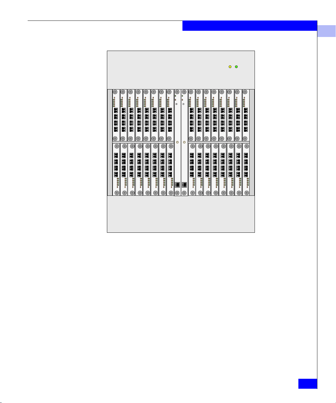
ED-140M The ED-140M (shown in Figure 1-1) is a 140-port director-class switch
that provides dynamic switched connections between Fibre Channel
servers and devices in a Storage Area Network (SAN) environment.
Directors are managed and controlled through the Connectrix service
processor. Remote user workstations can also be used in addition to a
server for remote management and control of directors.
EC-1200 Overview
1-3

EC-1200 Connectrix Cabinet
1
Key features of the ED-140M include:
◆ 140 ports of non-blocking 2 Gb/s (gigabit per second) Fibre
Channel switching in a 12U form factor.
◆ Redundant CTPs, SBARs, power, and cooling units.
◆ Hot-replaceable port cards, optics, CTPs, SBARs, power, and
cooling units.
◆ Online microcode upgrades.
◆ Management, maintenance, and serviceability features through
Connectrix Manager.
◆ E_Port compatibility with installed base of ED-64Ms, ED-1032s,
and DS-xxMs.
◆ LC-based Fibre Channel connector system.
◆ Up to three ED-140Ms in a single EC-1200, providing up to 420
director-class ports per cabinet.
◆ Web browser and SNMP support.
◆ Support for all operating systems, HBAs, and drivers supported
by the Connectrix ED-1032 in the current EMC Support Matrix.
1-4
Connectrix v6.02 Planning Guide
EC-1200 Connectrix Cabinet
1
Figure 1-1 ED-140M
Multiple directors and the service processor communicate on a LAN
through one or more 10/100Base-T Ethernet hubs. Up to four
Ethernet hubs (one in each cabinet) can be connected together in a
star, or hub and spoke manner, such that they all connect back to the
central hub/cabinet where the controlling service processor resides
(as opposed to being daisy-chained together). (Refer to Figure 1-13 on
page 1-19.)
The director’s Fibre Channel technology provides high-performance
scalable bandwidth (2 Gb/s), highly available operation, redundant
switched data paths, long transmission distances (up to 20 km), and
high device population.
The director supports Open Systems Interconnection (OSI)
computing environments and provides data transmission and flow
EC-1200 Overview
1-5

EC-1200 Connectrix Cabinet
1
control between device node ports (N_Ports) as dictated by the Fibre
Channel Physical and Signaling Interface (FC-PH 4.3).
ED-64M The ED-64M (shown in Figure 1-2) is a 64-port director-class switch
that provides dynamic switched connections between Fibre Channel
servers and devices in a Storage Area Network (SAN) environment.
Directors are managed and controlled through the Connectrix service
processor. Remote user workstations can also be used in addition to a
server for remote management and control of directors.
Key features of the ED-64M include:
◆ 64 ports of non-blocking 2 Gb/s (gigabit per second) Fibre
Channel switching in a 9U form factor.
◆ Redundant CTPs, SBARs, power, and cooling units.
◆ Hot-replaceable port cards, optics, CTPs, SBARs, power, and
cooling units.
◆ Online microcode upgrades.
◆ Management, maintenance, and serviceability features through
Connectrix Manager.
◆ E_Port compatibility with installed base of ED-64Ms, ED-140Ms,
ED-1032s, and DS-xxMs.
◆ LC-based Fibre Channel connector system.
1-6
◆ Up to four ED-64Ms in a single EC-1200, providing up to 256
director-class ports per cabinet.
◆ Web browser and SNMP support.
◆ Support for all operating systems, HBAs, and drivers supported
by the Connectrix ED-1032 in the current EMC Support Matrix.
Connectrix v6.02 Planning Guide
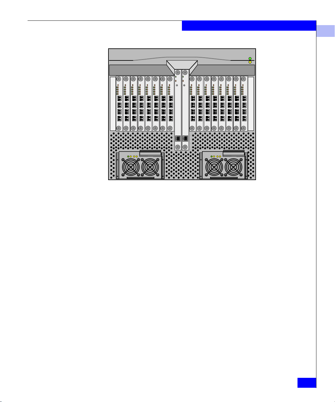
Figure 1-2 ED-64M
Multiple directors and the service processor communicate on a LAN
through one or more 10/100Base-T Ethernet hubs. Up to four
Ethernet hubs (one in each cabinet) can be connected together in a
star, or hub and spoke manner, such that they all connect back to the
central hub/cabinet where the controlling service processor resides
(as opposed to being daisy-chained together). (Refer to Figure 1-13 on
page 1-19.)
EC-1200 Connectrix Cabinet
1
The director’s Fibre Channel technology provides high-performance
scalable bandwidth (2 Gb/s), highly available operation, redundant
switched data paths, long transmission distances (up to 20 km), and
high device population.
The director supports Open Systems Interconnection (OSI)
computing environments and provides data transmission and flow
control between device node ports (N_Ports) as dictated by the Fibre
Channel Physical and Signaling Interface (FC-PH 4.3).
ED-1032 The ED-1032 is a previous-generation 32-port Fibre Channel director.
(Refer to ED-64M on page 1-6 for a description of the current
director.)
EC-1200 Overview
1-7

EC-1200 Connectrix Cabinet
1
DS-32M, DS-32M2 The Connectrix DS-32M/DS-32M2 (shown in Figure 1-3) provides
high-performance connections between computers, storage devices,
and other peripherals in an open systems Fibre Channel switched
network.
2
EMC
Figure 1-3 DS-32M/DS-32M2
The DS-32M can transfer data at 1.0625 Gb/s (gigabits per second),
and the DS-32M2 can transfer data at 2.125 Gb/s, through each port
at distances up to 500 meters using 50/125-micron multimode
fiber-optic cable with shortwave laser transceivers and up to 20
kilometers using 9/125 micron single-mode fiber-optic cable with
longwave laser transceivers.
Key features of the DS-32M/DS-32M2 include:
◆ 32 ports of non-blocking 1 Gb/s or 2 Gb/s Fibre Channel
switching in a 1.5U form factor.
1-8
◆ Redundant power and cooling units.
◆ Hot-replaceable optics, power, and cooling units.
◆ On-line microcode upgrades.
◆ Management, maintenance, and serviceability features through
Connectrix Manager.
◆ E_Port compatibility with installed base of ED-64Ms, ED-140Ms,
ED-1032s, and DS-xxMs.
◆ LC-based Fibre Channel connector system.
◆ Embedded Web Server.
◆ Mounting in EC-1200, CLARiiON, or customer-supplied rack.
◆ Up to 12 DS-32Ms and/or DS-32M2s in a single EC-1200,
providing up to 384 departmental-class ports per cabinet.
◆ Web browser, SNMP, and CLI support.
◆ Support for all operating systems, HBAs, and drivers supported
by the Connectrix ED-1032 in the current EMC Support Matrix.
Connectrix v6.02 Planning Guide
EC-1200 Connectrix Cabinet
The DS-32M/DS-32M2 is managed and controlled through one of
these:
◆ The Connectrix Manager and DS-32M/DS-32M2 Product
Manager applications installed on the Connectrix service
processor in an EC-1200 cabinet.
◆ A customer system with an Internet connection to the embedded
Web Server interface installed on the switch.
The DS-32M/DS-32M2 can be installed on a table or desk top,
mounted in an EMC EC-1200 equipment cabinet, or mounted in any
standard 19-inch equipment rack.
Multiple switches and the Connectrix service processor communicate
on a LAN through one or more 10Base-T Ethernet hubs.
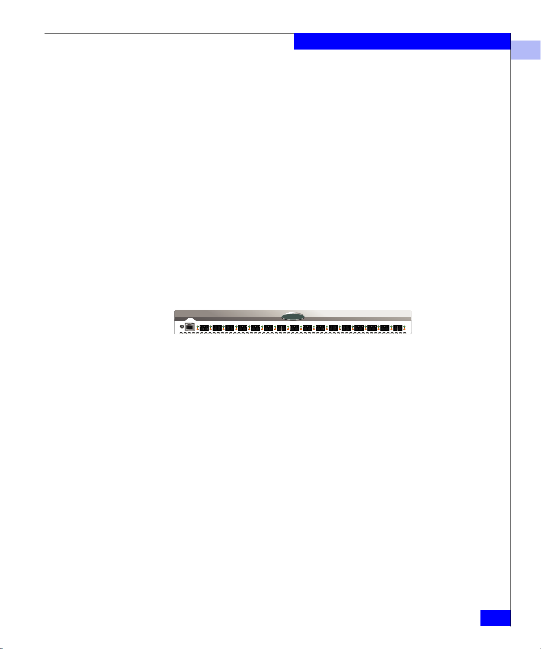
DS-16M, DS-16M2 The DS-16M/DS-16M2 (shown in Figure 1-4) is a 16-port Fibre
Channel switch that provides high-performance connections between
computers, storage devices, and other peripherals in an Open
Systems Fibre Channel switched network.
2
EMC
1
Figure 1-4 DS-16M/DS-16M2
The DS-16M can transfer data at 1.0625 Gb/s (gigabits per second),
and the DS-16M2 can transfer data at 2.125 Gb/s, through each port
at distances up to 500 meters using 50/125-micron multimode
fiber-optic cable with shortwave laser transceivers and up to 20
kilometers using 9/125 micron single-mode fiber-optic cable with
longwave laser transceivers.
Key features of the DS-16M/DS-16M2 include:
◆ 16 ports of non-blocking 1 Gb/s or 2 Gb/s Fibre Channel
switching in a 1U form factor.
◆ Redundant power and cooling units.
◆ Hot-replaceable optics, power, and cooling units.
◆ On-line microcode upgrades.
◆ Management, maintenance, and serviceability features through
Connectrix Manager.
EC-1200 Overview
1-9

EC-1200 Connectrix Cabinet
1
◆ E_Port compatibility with installed base of ED-64Ms, ED-140Ms,
ED-1032s, and DS-xxMs.
◆ LC-based Fibre Channel connector system.
◆ Embedded Web Server.
◆ Mounting in EC-1200, CLARiiON, or customer-supplied rack.
◆ Up to 12 DS-16Ms in a single EC-1200, providing up to 192
departmental-class ports per cabinet.
◆ Web browser, SNMP, and CLI support.
◆ Support for all operating systems, HBAs, and drivers supported
by the Connectrix ED-1032 in the current EMC Support Matrix.
The DS-16M/DS-16M2 is managed and controlled through one of
these:
◆ The Connectrix Manager and DS-16M Product Manager
applications installed on the Connectrix service processor in an
EC-1200 cabinet.
◆ A customer system with an Internet connection to the embedded
Web Server interface installed on the switch.
.
1-10
The DS-16M/DS-16M2 can be installed on a table or desk top,
mounted in an EMC EC-1200 equipment cabinet, or mounted in any
standard 19-inch equipment rack.
Connectrix v6.02 Planning Guide

EC-1200 Connectrix Cabinet
1
Guidelines for Installing Directors and Switches
The EC-1200 contains 36 units (36u) of available rack-mount height.
director and switch heights are:
Model Height
ED-1032 18u
ED-140M 12u
ED-64M 9u
DS-32M, DS-32M2 1.5u
DS-16M, DS-16M2 1u
With this in mind, here are some guidelines for installation:
◆ Install the heaviest units from the bottom up.
◆ DS-xxMs should be installed to allow 3u of rack height per
switch. 3u per switch is necessary to facilitate organizing and
managing the fiber-optic cables in the cabinet and to maintain
proper airflow and ventilation.
◆ Unless the cabinet will will be loaded with the the maximum
configuration of 12 DS-xxMs, leave 9u (or 18u if possible) of space
at the bottom of the cabinet for possible future installation of one
or more ED-64Ms or ED-140Ms.
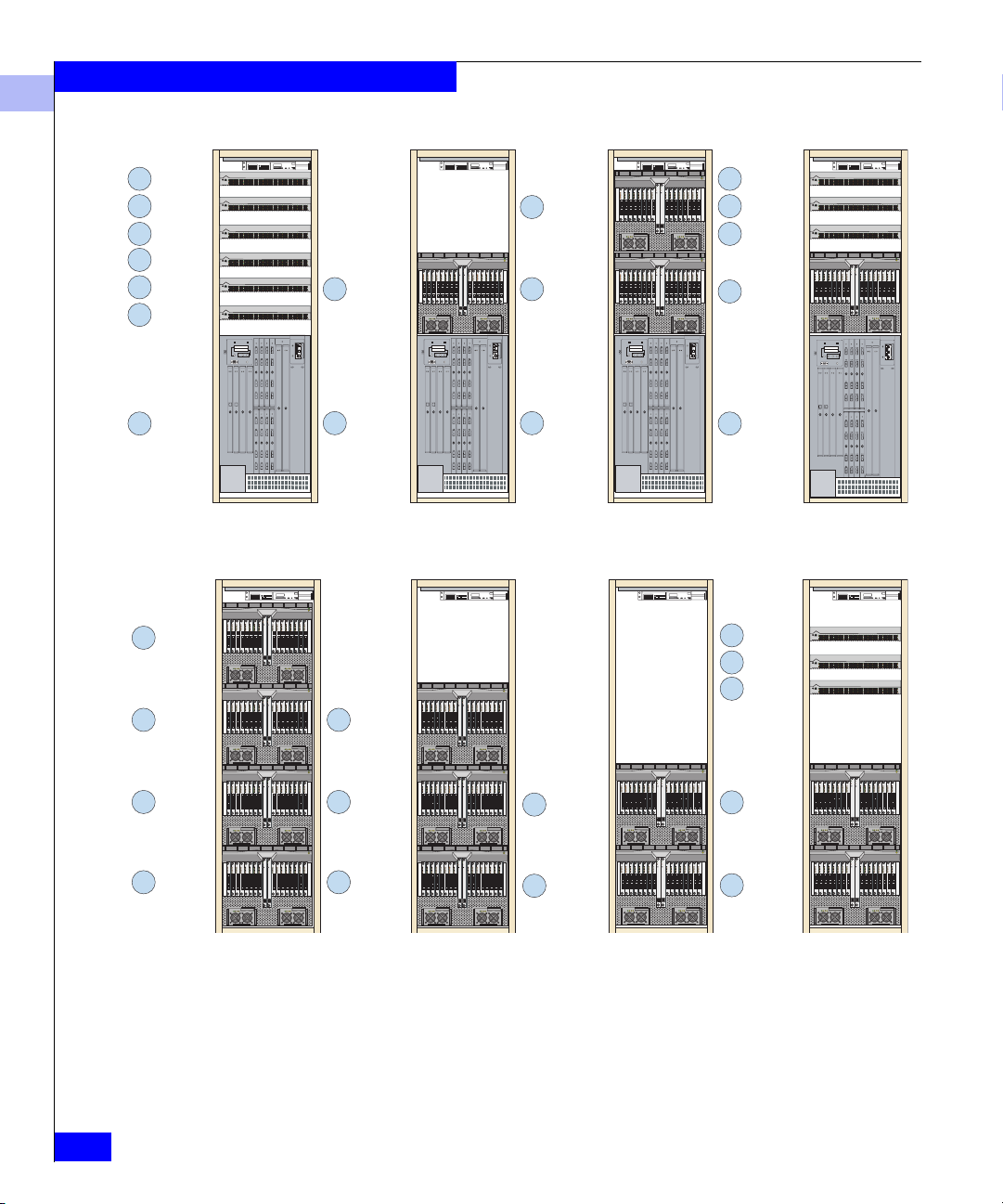
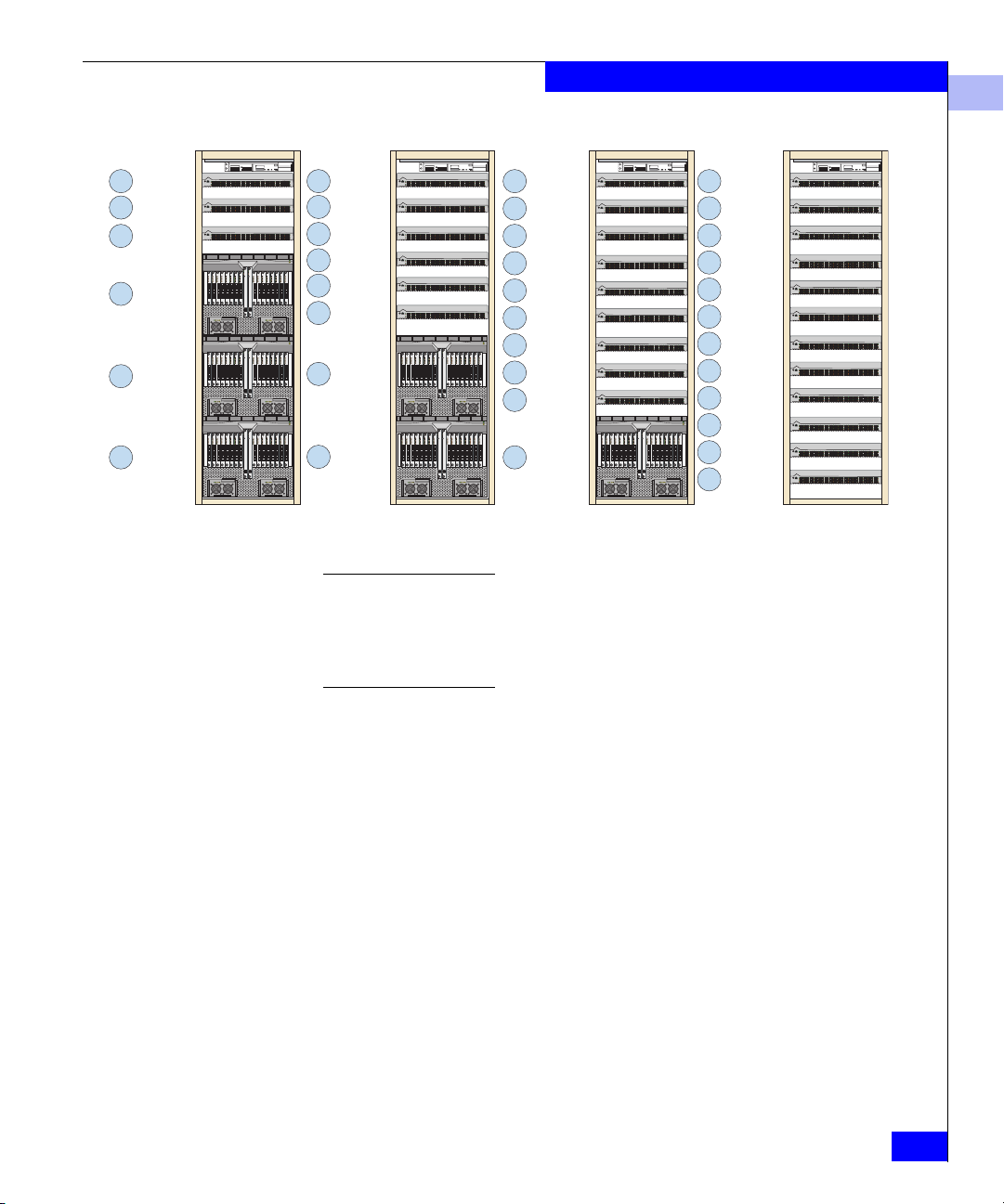
In addition to the base components listed under Base Configuration on
page 1-2, each EC-1200 can hold several combinations of ED-140Ms,
ED-64Ms, and DS-xxMs. Figure 1-5 through Figure 1-10 show some
examples; the numbers in circles represent the recommended order of
installation.
DS-xxMs can also be mounted in the CLARiiON product cabinet or a
standard EIA cabinet. For additional information, refer to the Connectrix
DS-16M and DS-32M Installation and Service Manual (P/N 014003065).
EC-1200 Overview
1-11
EC-1200 Connectrix Cabinet
1
21DS-xxM
3 DS-xxM
4
DS-xxM
5 DS-xxM
6 DS-xxM
7
DS-xxM
ED-1032
ED-64M
4
3
ED-64M
ED-64M3
ED-64M
2
1
ED-1032
ED-64M
2
1
ED-1032
Figure 1-5 EC-1200 Cabinet Configuration Examples 1 – 4
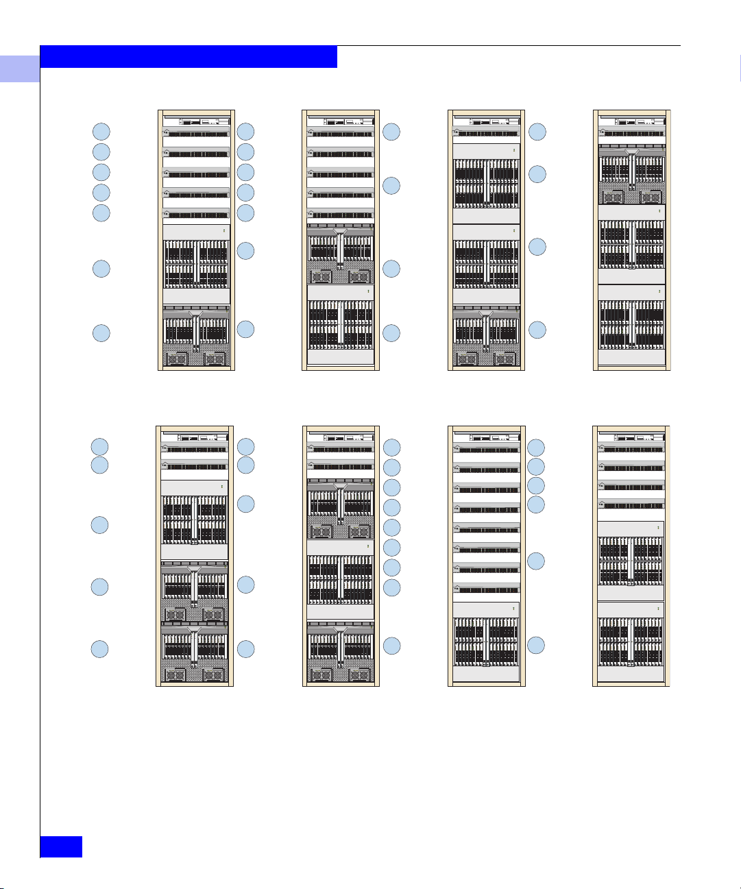
3
ED-64M
3
DS-xxM
4 DS-xxM
5 DS-xxM
ED-64M
2
1
ED-1032
3
DS-xxM
4
DS-xxM
5
DS-xxM
1-12
ED-64M
2
ED-64M1
ED-64M
2
ED-64M1
Figure 1-6 EC-1200 Cabinet Configuration Examples 5– 8
Connectrix v6.02 Planning Guide
2
ED-64M
ED-64M1
2
ED-64M
ED-64M1
EC-1200 Connectrix Cabinet
1
DS-xxM
4
5 DS-xxM
6 DS-xxM
3
ED-64M
2
ED-64M
ED-64M
1
DS-xxM
3
4
DS-xxM
5
DS-xxM
6
DS-xxM
7 DS-xxM
8 DS-xxM
2
ED-64M
ED-64M
1
2 DS-xxM
3 DS-xxM
4 DS-xxM
5 DS-xxM
6 DS-xxM
7 DS-xxM
8 DS-xxM
9 DS-xxM
10 DS-xxM
ED-64M1
Figure 1-7 EC-1200 Cabinet Configuration Examples 9 – 12
The order of installation in the two examples on the right in Figure 1-7
reflects inital installation of fewer than the maximum number of units,
allowing space for future installation of additional directors and/or switches
in the lower half of the cabinet. If these additonal units are installed, their
order would follow that shown in the figure.
1 DS-xxM
2 DS-xxM
3 DS-xxM
4 DS-xxM
5 DS-xxM
6 DS-xxM
7 DS-xxM
8 DS-xxM
9 DS-xxM
10 DS-xxM
11 DS-xxM
12 DS-xxM
EC-1200 Overview
1-13
EC-1200 Connectrix Cabinet
1
3 DS-xxM
4 DS-xxM
5 DS-xxM
6 DS-xxM
7 DS-xxM
2
ED-140M
ED-64M1
4 DS-xxM
5 DS-xxM
ED-140M
3
ED-64M2
3 DS-xxM
4 DS-xxM
5 DS-xxM
6 DS-xxM
7 DS-xxM
ED-64M2
1
ED-140M
4 DS-xxM
3
ED-140M
ED-140M
2
ED-64M1
Figure 1-8 EC-1200 Cabinet Configuration Examples 13 – 16
4 DS-xxM
5 DS-xxM
ED-64M3
2
ED-140M
2 DS-xxM
3 DS-xxM
4 DS-xxM
5 DS-xxM
6 DS-xxM
7 DS-xxM
8 DS-xxM
9 DS-xxM
4
DS-xxM
ED-64M
3
ED-140M
2
ED-140M1
3 DS-xxM
4 DS-xxM
5 DS-xxM
6 DS-xxM
2
ED-140M
1-14
ED-64M1
ED-64M1
Figure 1-9 EC-1200 Cabinet Configuration Examples 17 – 20
Connectrix v6.02 Planning Guide
1
ED-140M
ED-140M
1
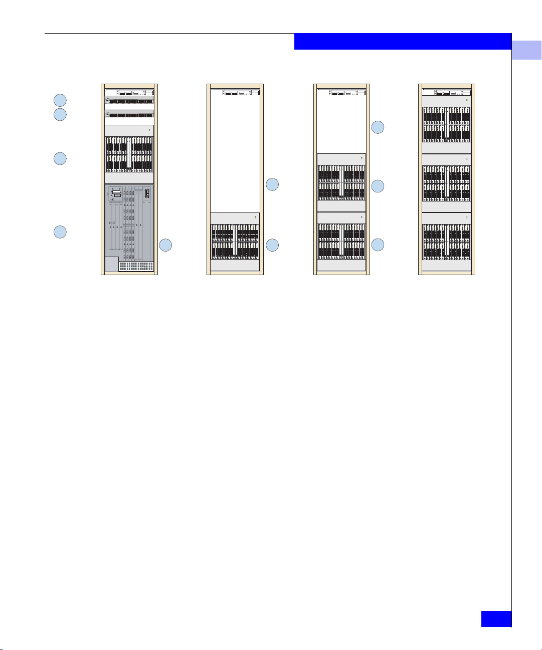
3 DS-xxM
4 DS-xxM
ED-140M
2
1
ED-1032
ED-140M
2
ED-140M1
Figure 1-10 EC-1200 Cabinet Configuration Examples 21 – 24
ED-140M
1
2
EC-1200 Connectrix Cabinet
1
ED-140M3
ED-140M
ED-140M1
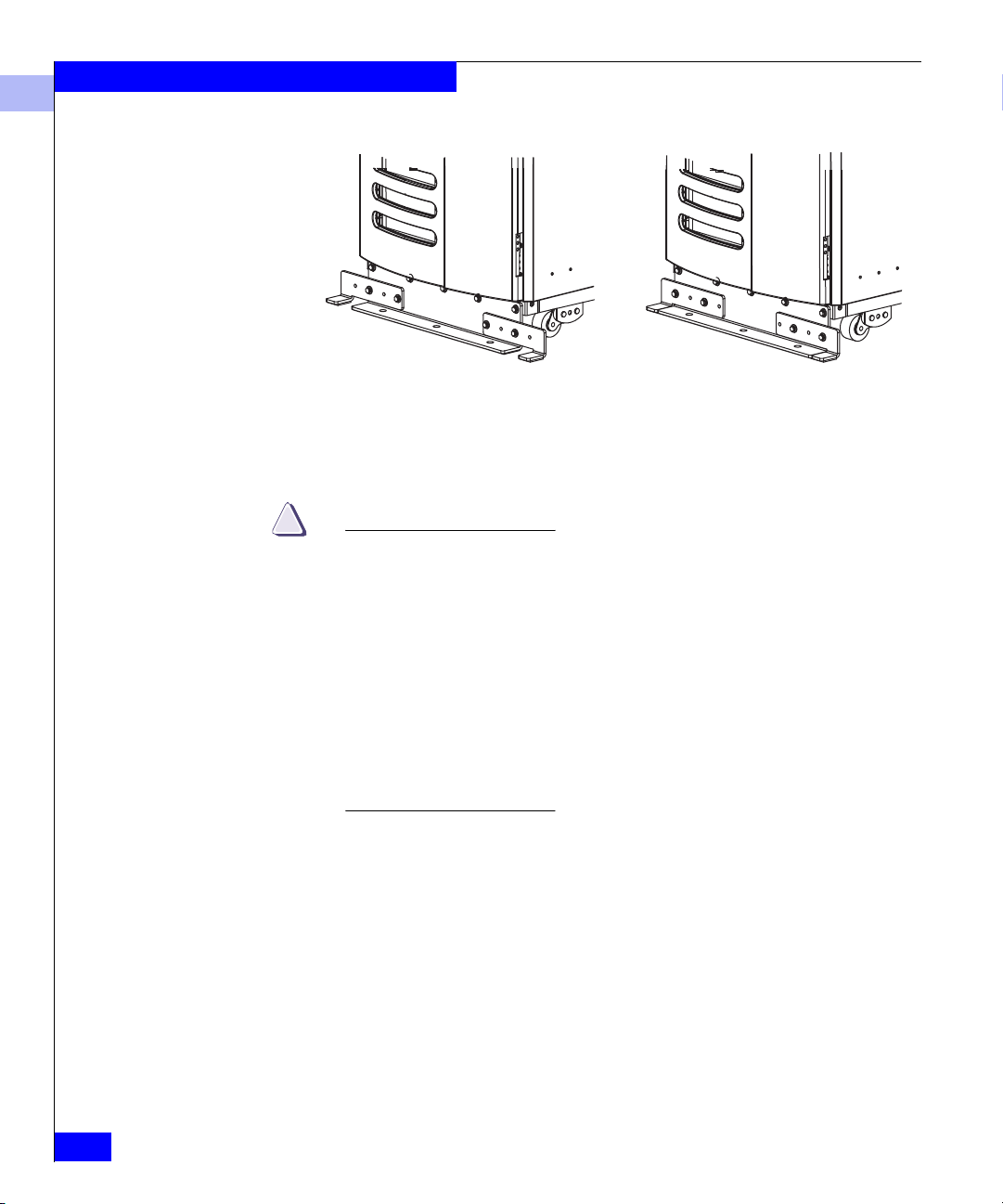
Stabilizer/Outrigger
Brackets
Connectrix stabilizer/outrigger brackets (P/N 100-605-014) mount to
the bottom front and rear of the EC-1200 cabinet to prevent tipping.
When the EC-1200 cabinet is positioned such that it is not
immediately adjacent (within 2 inches) to another equipment cabinet,
the stabilizer/outrigger brackets must be positioned in their
outermost position. (Refer to Figure 1-11.) If the cabinet is positioned
within 2 inches of another equipment cabinet, the outrigger brackets
can be positioned in their innermost position.
Any side of the EC-1200 cabinet that is not within 2 inches of another
equipment cabinet should have that side’s outriggers positioned in
the outermost position. These rules apply not only for initial
installation, but also if the EC-1200 switch/director configuration is
altered at a later date.
EC-1200 Overview
1-15
EC-1200 Connectrix Cabinet
1
Outermost Position
Figure 1-11 Stabilizer/Outrigger Bracket Positions
Figure 1-11 shows the front of the cabinet. Installation of the rear
brackets is similar.
!
CAUTION
EMC recommends keeping the Connectrix Stabilizer / Outrigger
brackets , P/N 100-605-014, on the EC-1200 cabinet at all times.
When the cabinet is positioned such that it is not immediately
adjacent (within 2 inches) to another equipment cabinet, the
stabilizer bracket outriggers must be positioned in their outermost
position. If the cabinet is positioned within 2 inches of another
equipment cabinet, the outrigger brackets can be positioned in
their innermost position. Any side of the EC-1200 cabinet that is
not within 2 inches of another equipment cabinet should have that
side’s outriggers positioned in the outermost position. These rules
apply not only for initial installation, but also if the EC-1200 switch
and/or director configuration is altered at a later date.
Innermost Position
1-16
Connectrix v6.02 Planning Guide
 Loading...