

Page 1

EMC Enterprise Storage Network
Connectrix
EC-1100 System
USER GUIDE
P/N 300-600-001
REV D
EMC Corporation 171 South Street, Hopkinton, MA 01748-9103
Corporate Headquarters: (508) 435-1000, (800) 424-EMC2 Fax: (508) 435-5374 Service: (800) SVC-4EMC
Page 2

Copyright © 2000 EMC Corporation. All rights reserved.
Printed March 2000
No part of this publication may be reproduced or distributed in any form or by any means, or stored in a
database or retrieval system, without the prior written consent of EMC Corporation.
The information contained in this document is subject to change without notice. EMC Corporation assumes
no responsibility for any errors that may appear.
All computer software programs, including but not limited to microcode, described in this document are
furnished under a license, and may be used or copied only in accordance with the terms of such license.
EMC either owns or has the right to license the computer software programs described in this document.
EMC Corporation retains all rights, title and interest in the computer software programs.
EMC Corporation makes no warranties, expressed or implied, by operation of law or otherwise, relating to
this document, the products or the computer software programs described herein. EMC CORPORATION
DISCLAIMS ALL IMPLIED WARRANTIES OF MERCHANTIBILITY AND FITNESS FOR A PARTICULAR
PURPOSE. In no event shall EMC Corporation be liable for (a) incidental, indirect, special, or consequential
damages or (b) any damages whatsoever resulting from the loss of use, data or profits, arising out of this
document, even if advised of the possibility of such damages.
Regulatory Agency Information
EMC Connectrix has been extensively tested and certified to meet UL1950, CSA 950, IEC 950/EN 60950
Safety of Information Technology Equipment Including Electrical Business Equipment; FCC Rules Part 15
Subpart B; CISPR22 Class A; EN55022; EN50082-1.
This class A digital apparatus complies with Canadian ICES-003.
Cet appareil numérique de la classe A est conforme à la norme NMB-003 du Canada.
Warning! This is a Class A product. In a domestic environment this product may cause radio interference
in which case the user may be required to take adequate measures.
Achtung! Dieses ist ein Gerät der Funkstörgrenzwertklasse A. In Wohnbereichen können bei Betrieb
dieses Gerätes Rundfunkstörungen auftreten, in welchen Fällen der Benutzer für entsprechende
Gegenmaßnahmen verantwortlich ist.
Attention! Ceci est un produit de Classe A. Dans un environnement domestique, ce produit risque de créer
des interférences radioélectriques, il appartiendra alors à l'utilisateur de prendre les mesures spécifiques
appropriées.
ii
Connectrix EC-1100 System User Guide
Page 3

This equipment generates, uses, and may emit radio frequency energy. The equipment has been type tested
and found to comply with the limits for a Class A digital device pursuant to Part 15 of FCC rules, which are
designed to provide reasonable protection against such radio frequency interference.
Operation of this equipment in a residential area may cause interference in which case the user at his own
expense will be required to take whatever measures may be required to correct the interference.
Any modifications to this device - unless expressly approved by the manufacturer - can void the user’s
authority to operate this equipment under part 15 of the FCC rules.
Trademark Information
EMC2, EMC, and Symmetrix are registered trademarks and Connectrix, Connectrix Manager, and PowerPath are trademarks of EMC Corporation.
HP and HP-UX are registered trademarks of Hewlett-Packard Company.
Zip is a registered trademark of Iomega Corporation.
Microsoft, Windows, Windows 95, Windows 98, Windows NT, Windows 2000, and Internet Explorer are registered trademarks of Microsoft
Corporation.
Pentium is a registered trademark of Intel Corporation.
IBM and AIX are registered trademarks of International Business Machines, Inc.
QuikSync is a trademark of Iomega Corporation.
Netscape Navigator is a registered trademark of Netscape Communications Corporation.
Sun, Solaris, and Java are trademarks of Sun Microsystems, Inc.
UNIX is a registered trademark in the United States and other countries and is licensed exclusively through X/Open Company Ltd.
All other trademarks used herein are the property of their respective owners.
Connectrix EC-1100 System User Guide
iii
Page 4

iv
Connectrix EC-1100 System User Guide
Page 5

Contents
Preface.............................................................................................................................xv
Chapter 1 Overview
The Connectrix Environment..........................................................1-2
EC-1100 Features...............................................................................1-5
Ethernet Hub Overview...................................................................1-7
Connectrix Service Processor Overview........................................1-8
Connectrix Manager Overview ......................................................1-9
Chapter 2 Connectrix Manager Administration
Connectrix Manager Software Operation .....................................2-2
User Administration.......................................................................2-16
Configuring EMC ControlCenter .................................................2-23
Managing Remote Access to the Service Processor...................2-24
Product Administration.................................................................2-31
Backing Up and Restoring Connectrix Manager Data..............2-42
SNMP MIB .......................................................................................2-44
Chapter 3 Fabric Manager
Opening the Fabric Manager...........................................................3-2
Fabric Manager Views......................................................................3-4
Fabric Manager Navigation Control Panel ...................................3-6
The Alert Panel..................................................................................3-8
Using the Topology View.................................................................3-9
Using the Zoning View ..................................................................3-12
Connectrix EC-1100 System User Guide
v
Page 6

Contents
Chapter 4 Fabric Zoning
Zoning Concepts...............................................................................4-2
Configuring and Managing Zoning...............................................4-6
Merging Zoned Fabrics..................................................................4-29
Zoning Tasks Reference Chart ......................................................4-31
Backing Up Zoning Configurations.............................................4-35
Chapter 5 Connectrix Manager Logs
Audit Log...........................................................................................5-2
Event Log...........................................................................................5-4
Session Log ........................................................................................5-6
Product Status Log ...........................................................................5-8
Exporting Log Files ........................................................................5-10
Appendix A Connectrix Manager Software Messages
Appendix B Setting the ED-1032 Network Addresses
IP Address ........................................................................................ B-2
Subnet Mask .................................................................................... B-4
Gateway Address ............................................................................ B-5
MAC Address .................................................................................. B-6
Appendix C Remote Workstation Installation
Windows Workstations ..................................................................C-2
Solaris Workstations .......................................................................C-9
HP-UX Workstations ....................................................................C-15
Appendix D Specifications
EC-1100 .............................................................................................D-2
Connectrix Service Processor ........................................................D-4
Appendix E Upgrading to a Single Service Processor Environment
Overview .......................................................................................... E-2
Consolidating Service Processors ................................................. E-4
Reconfiguring the Client After a Server Failure ......................... E-7
vi
Connectrix EC-1100 System User Guide
Page 7

Appendix F Power-on and Power-off Procedures
Power On Procedure .......................................................................F-2
Power Off Procedure ......................................................................F-5
Glossary
Sales and Service Locations
Index
Contents
Connectrix EC-1100 System User Guide
vii
Page 8

Contents
viii
Connectrix EC-1100 System User Guide
Page 9

Figures
1-1 Typical EC-1100 Master Cabinet ................................................................ 1-3
1-2 The EC-1100 in an Enterprise Environment ............................................. 1-4
2-1 Connectrix Manager Login Window ......................................................... 2-3
2-2 Connectrix Manager Main Window .......................................................... 2-4
2-3 Session View ................................................................................................ 2-10
2-4 Fabric Manager with Topology View ...................................................... 2-12
2-5 ISL Properties Window ............................................................................. 2-13
2-6 Fabric Manager with Zoning View .......................................................... 2-14
2-7 Configure Users Dialog Box ..................................................................... 2-16
2-8 New User Dialog Box ................................................................................. 2-19
2-9 Modify User Dialog Box ............................................................................ 2-20
2-10 Configure SNMP Dialog Box .................................................................... 2-23
2-11 Network Configuration Dialog Box ......................................................... 2-26
2-12 TCP/IP Configuration Window ............................................................... 2-27
2-13 Session View ................................................................................................ 2-28
2-14 Session Options Dialog Box ...................................................................... 2-29
2-15 New Product Dialog Box ........................................................................... 2-31
2-16 Modify Network Address Dialog Box ..................................................... 2-32
2-17 Product Properties Window ..................................................................... 2-33
2-18 Configure E-Mail Dialog Box .................................................................... 2-36
2-19 Test Remote Notification Dialog Box ...................................................... 2-37
2-20 Verification of Remote Notification Test ................................................. 2-37
2-21 Configure Ethernet Events Dialog Box ................................................... 2-38
2-22 Configure Nicknames Dialog Box ............................................................ 2-39
2-23 Add Nickname Dialog Box ....................................................................... 2-40
2-24 Connectrix Manager Web Page ................................................................ 2-45
3-1 Connectrix Manager’s Fabric View ............................................................ 3-2
3-2 Topology View Showing Interswitch Links ............................................. 3-4
3-3 Zoning View Showing Active Zone Set .................................................... 3-5
3-4 Topology View Properties Dialog Box .................................................... 3-10
Connectrix EC-1100 System User Guide
ix
Page 10

Figures
3-5 ISL Properties Dialog Box .......................................................................... 3-11
3-6 Zoning View with Active Zone Set .......................................................... 3-12
4-1 Zone Sets Dialog Box .................................................................................... 4-7
4-2 New Zone Set Dialog Box ............................................................................ 4-8
4-3 New Zone Dialog Box .................................................................................. 4-9
4-4 Display with Add by World Wide Name Selected ................................ 4-10
4-5 Ports and WWNs Added to Members in Zone Section ......................... 4-11
4-6 New Zone Dialog Box Actions Menu ...................................................... 4-12
4-7 Zone Sets Dialog Box .................................................................................. 4-13
4-8 New Zone Set Dialog Box .......................................................................... 4-14
4-9 Activate Zone Set Dialog Box .................................................................... 4-15
4-10 Modify Zone Dialog Box ............................................................................ 4-17
4-11 Ports and WWNs Added to Members in Zone Section ......................... 4-19
4-12 Modify Zone Set Dialog Box ..................................................................... 4-21
4-13 Deactivate Zone Set Dialog Box ................................................................ 4-23
4-14 Find Zone Dialog Box ................................................................................. 4-24
4-15 Remove Zone Dialog Box .......................................................................... 4-24
4-16 Find WWN Dialog Box ............................................................................... 4-26
4-17 Remove World Wide Name Dialog Box .................................................. 4-26
4-18 Replace World Wide Name Dialog Box ................................................... 4-27
5-1 Connectrix Manager Audit Log .................................................................. 5-2
5-2 Connectrix Manager Event Log .................................................................. 5-4
5-3 Connectrix Manager Session Log ............................................................... 5-6
5-4 Connectrix Manager Product Status Log .................................................. 5-8
5-5 Export Log Files Dialog Box ...................................................................... 5-10
B-1 ED-1032 Operator Panel .............................................................................. B-2
C-1 Connectrix Management Web Page .......................................................... C-3
C-2 InstallAnywhere Security Warning ........................................................... C-4
C-3 Connectrix Manager Download Page ....................................................... C-5
C-4 Connectrix Manager Installer — Introduction Screen ............................ C-6
C-5 Connectrix Manager Installer — License Agreement ............................. C-6
C-6 Connectrix Manager Installer - Important Information ......................... C-7
C-7 Connectrix Manager Installer - Choose Install Folder ............................ C-7
C-8 Connectrix Manager Installer - End Screen .............................................. C-8
C-9 Connectrix Management Web Page ........................................................ C-10
C-10 InstallAnywhere Security Warning ......................................................... C-11
C-11 Connectrix Manager Download Page ..................................................... C-12
C-12 Connectrix Manager Installer — Introduction Screen .......................... C-13
C-13 Connectrix Manager Installer — License Agreement ........................... C-13
C-14 Connectrix Manager Installer - End Screen ............................................ C-14
C-15 Connectrix Management Web Page ........................................................ C-17
D-1 Cable Cutouts in Top of Cabinet ............................................................... D-2
E-1 IP Addresses in Multiswitch Environment .............................................. E-3
x
Connectrix EC-1100 System User Guide
Page 11

E-2 Connectrix Manager Login Window ......................................................... E-8
F-1 EC-1100 and ED-1032 Power Switches ...................................................... F-2
Figures
Connectrix EC-1100 System User Guide
xi
Page 12

Figures
xii
Connectrix EC-1100 System User Guide
Page 13

Tables
2-1 Operational States and Symbols ................................................................. 2-7
2-2 Types of User Rights .................................................................................. 2-17
2-3 Connectrix Manager Software User Rights Categories ........................ 2-18
4-1 Merging Fabrics — Results for Zone Configurations ........................... 4-30
4-2 Zoning Tasks Reference Chart .................................................................. 4-31
Connectrix EC-1100 System User Guide
xiii
Page 14

Tab les
xiv
Connectrix EC-1100 System User Guide
Page 15

Preface
As part of its effort to continuously improve and enhance the performance
and capabilities of EMC products, EMC periodically releases new revisions
of hardware and software. Therefore, some functions described in this
manual may not be supported by all revisions of Connectrix hardware or
software presently in use. If your Connectrix does not offer a function
described in this manual, please contact your EMC representative for a
hardware or software update.
This guide is part of the documentation set for the EMC Connectrix
EC-1100 Enterprise Storage Network System. This guide describes
the product features and components, and the basic operation of the
EC-1100 and its components. It is intended for data center
administrators, local area network (LAN) administrators, and
operations and customer support personnel who manage and
operate the product.
Organization This guide contains the following information:
• Chapter 1, Overview, provides an overview of the EC-1100,
including product features and components.
• Chapter 2, Connectrix Manager Administration, explains high-level
administration tasks, including an overview of the Connectrix
Manager application.
• Chapter 3, Fabric Manager, describes how to use the Fabric
Manager to monitor, configure, and manage the specific Fibre
Channel fabrics in which managed products operate.
• Chapter 4, Fabric Zoning, explains fabric zoning in detail and
contains instructions for using the features and dialog boxes
associated with zoning.
Connectrix EC-1100 System User Guide
xv
Page 16

Preface
• Chapter 5, Connectrix Manager Logs, includes information on
using the Connectrix Manager’s audit, event, session, and
product status logs.
• Appendix A, Connectrix Manager Software Messages, lists error
messages, with their explanations, that are generated by the
Connectrix Manager.
• Appendix B, Setting the ED-1032 Network Addresses, explains how
to change network addresses on the ED-1032.
• Appendix C, Remote Workstation Installation, explains how to load
the Connectrix Manager software onto a remote workstation
running the Windows (95/98/NT/2000), Solaris, or HP-UX
operating system.
• Appendix D, Specifications, lists physical and environmental
specifications.
• Appendix E, Upgrading to a Single Service Processor Environment,
explains how to upgrade the server/service processor
environment to allow multiswitch support from a single
Connectrix service processor.
• Appendix F, Power-on and Power-off Procedures, explains the
proper procedures for powering on and powering off the
Connectrix cabinet and its components.
xvi
Related
Documentation
• The Glossary defines terms, abbreviations, and acronyms used in
this manual.
Other EMC publications that provide additional information about
Connectrix and Symmetrix Fibre Channel are:
• Connectrix EC-1100 System Planning Guide, P/N 300-600-002
• Connectrix ED-1032 Director User Guide, P/N 300-600-004
• Connectrix Enterprise Storage Network System Topology Guide, P/N
300-600-008
• Symmetrix Fibre Channel Product Guide, P/N 200-999-642
Connectrix EC-1100 System User Guide
Page 17

Preface
Conventions Used in
this Manual
Text Conventions
This document uses the following text conventions:
• General text is in Palatino font.
• New terms or words to be emphasized are italicized.
• Names of buttons, LEDs, dialog boxes, commands, parameters,
files, and paths are bold.
•
Screen output is in Courier font.
•
User input is in bold Courier font.
•
REFERENCES TO SPECIFIC KEYBOARD KEYS ARE IN UPPERCASE AVANTGARDE FONT.
References to keys are shown in uppercase, but usually it does not matter
whether you use uppercase or lowercase when pressing a key.
When two or three keys are shown separated by dashes (for example,
ALT-E), this means you should press the keys simultaneously. (Do not
press the DASH key, unless specically instructed to do so.)
Notes, Cautions, and Warnings
EMC uses the following conventions for notes, cautions, and
warnings:
A note presents information that is important, but not hazard-related.
!
CAUTION
A caution contains information essential to avoid a hazard that can
cause minor personal or property damage if you ignore the
message.
WARNING
A warning contains information essential to avoid a hazard that can
cause severe personal injury, death, or substantial property damage
if you ignore the message.
Connectrix EC-1100 System User Guide
xvii
Page 18

Preface
DANGER
A danger notice contains information essential to avoid a hazard
that will
cause severe personal injury, death, or substantial property
damage if you ignore the message.
Where to Get Help Obtain technical support by calling your local sales office.
For service, call:
United States: (800) 782-4362 (SVC-4EMC)
Canada: (800) 543-4782 (543-4SVC)
Worldwide: (508) 497-7901
and ask for Customer Service.
Your Comments Your suggestions will help us continue to improve the accuracy,
organization, and overall quality of the EMC publications. Please
e-mail us at techpub_comments@emc.com to let us know your
opinion or any errors concerning this manual.
xviii
Connectrix EC-1100 System User Guide
Page 19

The following warnings and cautions pertain throughout this
manual.
WARNING Trained service personnel only.
This unit has two power supply cords. To reduce the risk of electric
shock, disconnect both power supply cords before servicing.
Ground circuit continuity is vital for safe operation of the machine.
Never operate the machine with grounding conductors disconnected.
Remember to reconnect any grounding conductors removed for or
during any installation procedure.
Warnings and
Cautions
ATTENTION Resérvé au personnel autorisé.
Cet appareil comporte plus d'un cordon d'alimentation. Afin de
prévenir les chocs électriques, débrancher les deux cordons
d'alimentation avant de faire le dépannage.
Un circuit de terre continu est essentiel en vue du fonctionnement
sécuritaire de l'apareil. Ne jamais mettre l'appareil en marche lorsque
le conducteur de mise a la terre est débranché.
WARNUNG Nur für Fachpersonal.
Das Geraet hat mehr als eine Anschlussleitung. Zur Vermeidung der
Gefahr eines elektrischen Schlages sind vor dem öffnen beide
Anschlussleitungen vom Netz zu trennen.
STROMSTREUVERLUST: Gerät muss geerdet werden, bevor es am
Stromnetz angeschlossen wird.
Connectrix EC-1100 System User Guide
xix
Page 20

Warnings and Cautions
Additional Warnings
and Cautions
!
Before attempting to service a Connectrix unit, observe the following
additional Warnings and Cautions:
WARNING
The Connectrix contains no user-serviceable parts, so it should not be
moved or opened for any reason by untrained persons. If the
Connectrix needs to be relocated or repaired, only qualified personnel
familiar with safety procedures for electrical equipment and the
Connectrix hardware should access components inside the unit or
move the unit.
WARNING
The system operates at high voltages. To protect against physical
harm, power off the system whenever possible while servicing.
WARNING
In case of fire or other emergency, isolate the system’s power
involved and alert appropriate personnel.
CAUTION
Trained personnel are advised to exercise great care at all times
when working on the Connectrix unit. Remember to:
xx
• Remove rings, watches, or other jewelry and neckties before
you begin any procedures.
• Use caution near any moving part and any part that may start
unexpectedly such as fans, motors, solenoids, etc.
• Always use the correct tools for the job.
• Always use the correct replacement parts.
• Keep all paperwork, including incident reports, up to date,
complete, and accurate.
Static Precautions EMC incorporates state-of-the-art technology in its designs, including
the use of LSI and VLSI components. These chips are very susceptible
to damage caused by static discharge and need to be handled
accordingly.
Connectrix EC-1100 System User Guide
Page 21

Warnings and Cautions
!
CAUTION
Before handling Connectrix printed circuit boards or other
Symmetrix parts containing LSI and/or VLSI components, observe
the following precautions:
• Store all printed circuit boards in anti-static bags.
• Use a ground strap whenever you handle a printed circuit
board.
• Unless specifically designed for non-disruptive replacement,
never plug or unplug printed circuit boards with the power on.
Severe component damage may result.
Connectrix EC-1100 System User Guide
xxi
Page 22

Warnings and Cautions
xxii
Connectrix EC-1100 System User Guide
Page 23

Invisible Body Tag
1
Overview
This chapter provides a high-level overview of the Connectrix
EC-1100 cabinet and its major components, including:
• The Connectrix Environment...........................................................1-2
• EC-1100 Features................................................................................1-5
• Ethernet Hub Overview....................................................................1-7
• Connectrix Service Processor Overview.........................................1-8
• Connectrix Manager Overview........................................................1-9
Overview
1-1
Page 24

Overview
1
The Connectrix Environment
The Connectrix™ EC-1100 and its components play a critical role in
an enterprise-class, Fibre Channel connectivity management solution.
Key features of Connectrix include:
• High-performance, high-availability Connectivity Units with:
✦ Redundant power, cooling, and cards
✦ Automatic failover
✦ On-line repair of critical components
• Capacity and scalability — You can add more Connectivity Units
as the enterprise expands.
• Centralized management of multiple units through the
Connectrix Manager software:
✦ Up to four EC-1100 cabinets controlled through one central
Connectrix service processor
✦ Centralized control from local Connectrix service processor or
remote workstations
1-2
• Remote management:
✦ Concurrent support of up to four remote users and one dial-in
(or local) user.
✦ If there are many EC-1100 master cabinets (the ones with
service processors) in the enterprise, remote users can log into
the Connectrix service processor in any of them.
✦ SNMP-based network management applications, such as HP
OpenView
Connectivity Units. The EC-1100 supports the FibreAlliance
MIB for all Connectivity Units through one IP address.
Connectrix EC-1100 System User Guide
®
, can recognize and manage SNMP agents in the
®
Page 25

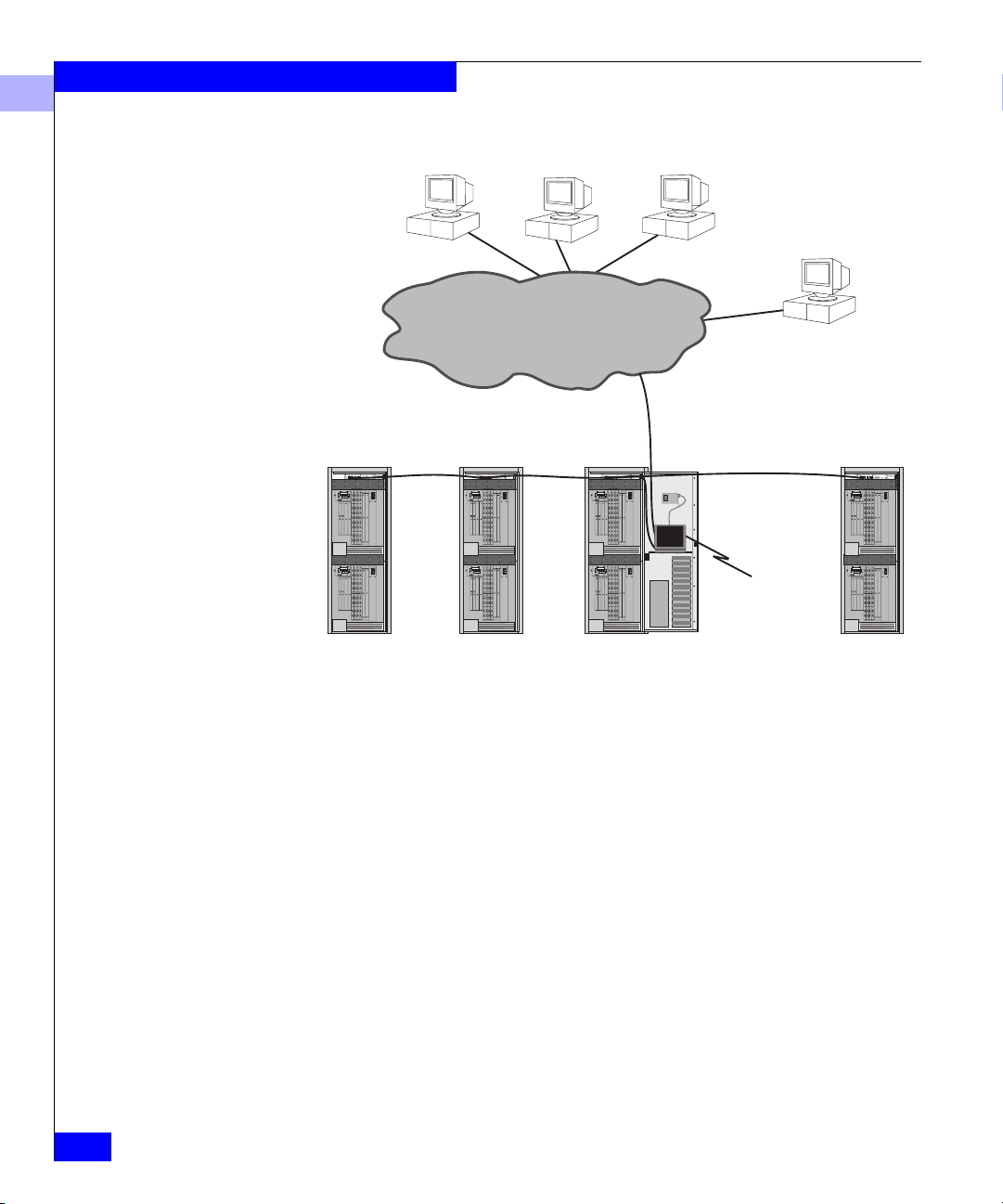
Figure 1-1 shows a typical EC-1100 master cabinet configuration.
Slave cabinets are similar, but with no service processor or Zip drive.
Ethernet
Hub
GPM
GPM GPM
GPM
CMM
CMM
CTP
CTP MPC MPC
Overview
1
Zip
Drive
ED-1032
ENET ENET
CTP
CTP MPC MPC
GPM
GPM
GPM GPM GPM
GPM GPM GPM
CMM
ED-1032
ENET ENET
GPM
GPM GPM GPM
Figure 1-1 Typical EC-1100 Master Cabinet
Connectrix
Service
Processor
Figure 1-2 shows the overall system management architecture
incorporating the EC-1100.
The Connectrix Environment
1-3
Page 26
Overview
1
Connectrix Manager User Workstations
SNMP
Management
Station
Data Center
Ethernet
Ethernet
GPM
GPMGPM
GPM
CMM
CMM
CTP
CTP MPC MPC
ENETENET
GPM
GPMGPM GPM
GPM
GPMGPM GPM
CMM
CTP
CTP MPC MPC
ENETENET
GPM
GPMGPM GPM
Ethernet
GPM
GPMGPM
GPM
CMM
CMM
CTP
CTP MPC MPC
ENETENET
GPM
GPMGPM GPM
GPM
GPMGPM GPM
CMM
CTP
CTP MPC MPC
ENETENET
GPM
GPMGPM GPM
GPM
GPMGPM
GPM
CMM
CMM
CTP
CTP MPC MPC
ENETENET
GPM
GPMGPM GPM
GPM
GPMGPM GPM
CMM
CTP
CTP MPC MPC
ENETENET
GPM
GPMGPM GPM
Slave Slave Master Slave
Figure 1-2 The EC-1100 in an Enterprise Environment
A single Connectrix service processor can be used to manage up to
four EC-1100 cabinets (including the master cabinet, which contains
the service processor). Multiple cabinets are connected through an
Ethernet hub in each cabinet, allowing expansion of the management
of your enterprise. A configuration requires at least one master
cabinet.
Ethernet
Connectrix
Service
Processor
To EMC Customer
Support Center
GPM
GPMGPM
GPM
CMM
CMM
CTP
CTP MPC MPC
ENETENET
GPM
GPMGPM GPM
GPM
GPMGPM GPM
CMM
CTP
CTP MPC MPC
ENETENET
GPM
GPMGPM GPM
1-4
Connectrix EC-1100 System User Guide
Page 27

EC-1100 Features
Overview
1
The EC-1100 cabinet provides a central management platform for
mounting, monitoring, and controlling Fibre Channel Connectivity
Units.
Connectivity
Manageability
The EC-1100 allows you to integrate multiple Fibre Channel
Connectivity Units (ED-1032 Directors, for example) into a single
point of management. You can start with what you need to manage
today’s environment, and add connectivity devices as your
management needs expand.
Each EC-1100 includes up to two ED-1032 enterprise Fibre Channel
Directors, each containing up to 32 Fibre Channel ports. The ED-1032
is a data center-class Fibre Channel Director that provides
high-performance, highly available operations and enterprise-class
manageability for an open systems environment.
The hardware and software components of the EC-1100 cabinet that
provide network manageability include:
• 24-port 10Base-T Ethernet hub, for connecting the managed
products to the Connectrix service processor, and for connecting
multiple cabinets.
• Connectrix service processor, a laptop computer to run the
Connectrix Manager software. Up to four cabinets can be
connected and managed by a single service processor (located in
one of the four cabinets).
®
• Zip
drive for backing up your configuration. An automated
backup process uses the Zip drive to protect essential Connectrix
management data. The drive is necessary only in the cabinet
containing the Connectrix service processor.
• Connectrix Manager software installed on the Connectrix service
processor. The software provides a central point of control for
managing the cabinet components, and is composed of the
Connectrix Manager and Product Manager plug-ins for each
managed product.
• A 56-Kbps (kilobytes per second) external modem, used for
service and support of the managed products.
EC-1100 Features
1-5
Page 28

Overview
1
Redundant Power Distribution
Cable Management
Redundant power features mean that the Fibre Channel Connectivity
Units are always available. The EC-1100 has dual AC power strips
and dual AC power inputs for redundant power distribution.
The EC-1100 contains two power switches, located in the center of the
rear door. Each switch controls AC power from one of the two power
sources to the cabinet.
The EC-1100 incorporates features that simplify cable management.
Cable hangers mounted inside the cabinet allow grouping of cables,
supporting up to 64 Fibre Channel links. Cables can be easily added,
replaced or rerouted. The structured fiber wiring system draws the
links away from the ED-1032 Directors so that directors or their
components can be added or replaced while the cabinet is on line.
The EC-1100 supports cable entry through the top of the cabinet. This
feature is for data centers that use ceiling-mounted cable trays
instead of raised floors. Figure D-1 on page D-2 shows the
dimensions of the cable openings.
1-6
Connectrix EC-1100 System User Guide
Page 29

Ethernet Hub Overview
ED-1032s and the Connectrix service processor connect through a
24-port 10Base-T Ethernet hub installed in each cabinet. The Ethernet
hubs provide out-of-band management services for each EC-1100.
When using multiple cabinets, the hubs are daisy-chained by
attaching RJ-45 patch cables and configuring each hub through its
Medium-Dependent Interface (MDI) switch.
The Ethernet hub is for the private EC-1100 network. The customer’s
data center network connects directly to the Connectrix service
processor’s 10/100 Ethernet connection.
Overview
1
LEDs
The Ethernet hub contains these LEDs:
• Power LED (green) on the rear of the hub
• Connection indicator LEDs (green) on front of unit (one for each
device connected to the Ethernet hub)
Ethernet Hub Overview
1-7
Page 30

Overview
1
Connectrix Service Processor Overview
The Connectrix service processor is a notebook PC that provides a
central point of control for up to four EC-1100 cabinets. The service
processor is required for installing, configuring, and managing the
ED-1032s.
Although cabinet components can perform normal operations
without a Connectrix service processor, the service processor should
operate at all times, to monitor operations, log events and
configuration changes, and report failures.
The Connectrix service processor is dedicated to the Connectrix
Management Services application, and should not be used for other
tasks. The Connectrix Management Services application provides
management services to the Connectrix Manager and its associated
Product Manager and Fabric Manager applications. It also
implements World-Wide Web and other server functions.
The Connectrix service processor contains two Ethernet adapters, one
10-BaseT and one 10/100 Mbps with RJ-45 connectors. The 10-Mbps
card is connected to the Ethernet hub in the cabinet to manage the
LAN segment containing the managed products. The 10/100 Mbps
card is used to connect to a customer intranet to allow access from
remote user workstations. The 10/100 data center connection can be
connected to the customer’s own hub or Ethernet switch.
1-8
The Connectrix Service Processor provides a web interface for easily
installing remote clients and accessing MIB source code.
Connectrix EC-1100 System User Guide
Page 31

Connectrix Manager Overview
The Connectrix Manager provides common support and
administration for both ED-1032s in the EC-1100 cabinet as well as an
access point for the ED-1032 Product Manager. The software’s
Java™-based GUI provides an intuitive, easy-to-use interface to the
managed products.
Overview
1
Management Services
Connectrix Manager Functionality
The Connectrix Manager provides specific management services
including:
• Session management for one or more remote Connectrix Manager
network connections
• Centralized database repository for configuration files, system
logs, firmware upgrades, and other entities
• Remote support and debug services
Through the Connectrix Manager, you can:
• Display an overview of operational status for each managed
product
• Define user names, passwords, and user rights for access to the
Connectrix Management Services application
• Define access rights to the managed products from remote user
workstations
• Define access to a specific Connectrix service processor and its
managed products
• Configure community names and network addresses for up to 12
SNMP trap recipients
• Configure E-mail notification for system events
• Display event, audit, product status, and session logs
• Open the Fabric Manager to manage a specific fabric
• Display an overview of all the fabrics managed by the Connectrix
Manager
• Open a Product Manager to manage and monitor a specific
product on the network
Connectrix Manager Overview
1-9
Page 32

Overview
1
• Identify new products and their network addresses to the
Connectrix service processor
• Enable/disable call-home capabilities
Product Manager Services
The Product Managers are installed on the Connectrix service
processor to provide local access to managed products. These
applications can also be installed on remote user workstations to
provide remote access through the data center Ethernet.
The Product Manager services include:
• Establishing and maintaining network connections to managed
products, such as ED-1032s
• Product configuration management
• Event and session logging
• Alert processing and user notification
• Initiation of the call-home procedure
• Network management and file transfer protocol (FTP) processing
1-10
Connectrix EC-1100 System User Guide
Page 33

Invisible Body Tag
2
Connectrix Manager
Administration
This chapter describes the basic administration tasks required to
manage your enterprise with the Connectrix Manager. It describes
how to monitor operation of managed products, access
administration options, manage users, and access on-line help.
This chapter includes the following sections:
• Connectrix Manager Software Operation ......................................2-2
• User Administration........................................................................2-16
• Configuring EMC ControlCenter ..................................................2-23
• Managing Remote Access to the Service Processor ....................2-24
• Product Administration..................................................................2-31
• Backing Up and Restoring Connectrix Manager Data ...............2-42
• SNMP MIB ........................................................................................2-44
Connectrix Manager Administration
2-1
Page 34

Connectrix Manager Administration
2
Connectrix Manager Software Operation
The Connectrix Manager is the central point of control for the
managed products in the EC-1100 cabinet. The software includes the
Connectrix Manager and Product Manager for the ED-1032.
Opening the Connectrix Manager
The Connectrix Manager is installed on the Connectrix service
processor at the factory. (Appendix C describes the installation.) To
open the Connectrix Manager, follow these steps.
1. Open the Connectrix Manager Login window (Figure 2-1), as
described below.
• If running locally on the service processor, the Login window
appears when the services start.
®
• On a Windows
95/98/2000 or Windows NT® system,
double-click the Connectrix Manager icon on your desktop, or
select the application from the Windows Start menu.
®
• On an HP-UX
a. Type
the user’s home directory and
or Solaris® system:
cd <home>/EFCM and press ENTER (where <home> is
EFCM is the default install
directory).
b. Type EFC_Manager and press ENTER at the command line
prompt.
2-2
Connectrix EC-1100 System User Guide
Page 35

Figure 2-1 Connectrix Manager Login Window
2. Enter your user name and password. (Both are case sensitive.) If
you have not been assigned a user name and password, use the
default user name Administrator and the default password
password.
Connectrix Manager Administration
2
3. Click the arrow at the right of the Connectrix field, then click the
name/address of the service processor to which you want to
connect. If you are logging in locally, the service processor’s host
name is localhost.
If login is successful, the Connectrix Manager main window
(Figure 2-2) appears.
Connectrix Manager Software Operation
2-3
Page 36

Connectrix Manager Administration
2
Window Layout
Navigation Control
2-4
Connectrix EC-1100 System User Guide
Figure 2-2 Connectrix Manager Main Window
As shown in Figure 2-2, the main window consists of four "panels":
• Title panel
• Navigation control panel
• Alert panel
• Main panel
Title Panel This panel indicates the type of view that is being displayed in the
main panel. In Figure 2-2, the title panel indicates that the Product
View is displayed in the main panel.
This panel contains icons that provide access to menu options, dialog
Panel
boxes, and on-line help. Use these operations to perform
Page 37

Connectrix Manager Administration
administration for the Connectrix Manager and Product Manager
functions.
Each icon has a pop-up menu, which is displayed by placing your
mouse cursor over the icon.
The icons and their pop-up menu options are:
• View — Provides access to each of the Connectrix Manager
views: Product, Fabric, and Session.
• Configure — Provides options for configuring and managing
users, products, sessions, and SNMP options:
✦ New product — Use this option to add a product to be
managed by the Connectrix Manager.
✦ Users — Use this option to display a list of current users who
can access the Connectrix service processor, and to establish
new users, delete users, modify information for existing users,
and establish or display user rights.
✦ Nicknames — Use this option to assign a nickname for a
worldwide name (WWN). For example, you might assign the
nickname SymmFA1A to a Symmetrix port’s WWN, instead
of using the more cryptic 8-byte worldwide name. You can
add or delete nicknames through this dialog box. Refer to
Configure Nicknames on page 2-38.
2
✦ Session Options — Use this option to allow or disallow access
to the Connectrix service processor from remote user
workstations. Refer to Modifying Session Parameters on
page 2-29.
✦ SNMP — Use this option to configure the SNMP agent that
runs on the Connectrix service processor and implements the
FibreAlliance Management Information Base (MIB).
• Logs — Provides access to all of the Connectrix Manager logs:
✦ Audit Log — Use this option to display a history of user
actions performed through the Connectrix Manager. Refer to
Audit Log on page 5-2.
✦ Event Log — Use this option to list abnormal error conditions
related to Connectrix Manager operation. Refer to Event Log
on page 5-4.
Connectrix Manager Software Operation
2-5
Page 38

Connectrix Manager Administration
2
✦ Session Log — Use this option to list the users who have
logged in and logged out of the Connectrix service processor.
Refer to Session Log on page 5-6.
✦ Product Status Log — Use this option to display the
operational status changes of each managed product. Refer to
Product Status Log on page 5-8.
• Maintenance — Provides tools for setting remote communication
options:
✦ Test Remote Notification — Use this option to test the remote
notification mechanisms that you have configured—E-mail
notification and the call-home feature. Refer to Tes t Remo te
Notification on page 2-36.
✦ Enable Call Home Event Notification — Use this option to
enable the call-home feature. Check/uncheck the box in the
dialog window to enable/disable the call-home feature. Refer
to Enable Call-Home Event Notification on page 2-34.
✦ Configure E-Mail — Use this option to configure network
addresses for administrators or others who should receive
notification of product events through E-mail. Refer to
Configuring E-mail Notification for Product Events on page 2-35.
2-6
✦ Configure Ethernet Events — Use this option to configure
Ethernet events and enable notification for all Product
Managers. An Ethernet event occurs when the Ethernet link
between the Connectrix service processor and the managed
product is lost. Refer to Configure Ethernet Events on page 2-37.
If E-mail notification is also enabled, an E-mail will be sent if
an Ethernet event occurs.
If call-home notification is also enabled, a call home will be
generated if an Ethernet event occurs.
For both E-mail and call-home, notification is generated after a
timer expires
• Help — Provides access to two menu options:
✦ Contents — Use this option to open the Connectrix Manager
on-line help window. The Contents, Index, and Glossary
items in the left frame of the Help window are hyperlinked to
topic text and graphics in the right frame.
Connectrix EC-1100 System User Guide
Page 39

Connectrix Manager Administration
✦ About — Use this option to display version and copyright
information for the Connectrix Manager.
• Logout/Exit — Has two options:
✦ Logout — Use this option to close the Connectrix Manager
window and return to the Login dialog box.
✦ Exit — Use this option to exit the Connectrix Manager
application.
Alert Panel This panel displays a color-coded alert symbol that indicates the most
critical status of any component managed by the Connectrix
Manager. For example, if a component in a managed product fails, a
red diamond with yellow background (most critical state) appears in
the alert panel, even if all other components are fully operational.
Table 2-1 Operational States and Symbols
Operational State Symbol
Operational
Network communication is established. All products are
operational and no failures are indicated.
2
Degraded
At least one product under management is operating in a
degraded mode and requires service. This condition is
typical when a redundant FRU fails and the backup FRU is
operational.
Failed
A product under management has failed and requires
immediate service.
Unknown
The Connectrix Manager cannot determine product status
because of a network communication failure between the
product and the Connectrix service processor, or because
the managed product is not responding. The link may
never have been established, or the link may have
malfunctioned.
This is a normal background indication when the managed
product is managed by another Service Processor.
Connectrix Manager Software Operation
2-7
Page 40

Connectrix Manager Administration
2
Main Panel This panel displays the view that you selected from the View icon’s
pop-up menu—Product View, Fabric View, or Session View.
(Figure 2-2 shows the Product View.)
Product View
Expanding an ED-1032
Name or Address
Monitoring Product
Operating Status
Executing Menu
Functions
When you start the Connectrix Manager, the default view in the main
panel is the Product View. The Product View provides a pictorial
overview of all ED-1032s that you can manage and monitor through
the Connectrix Manager. Icons representing each product include a
label with the product’s IP address or Domain Name Service (DNS)
host name. Functions in the Product View allow you to monitor
product operation, obtain product information, and administer the
management software.
Move the mouse cursor over a product icon to select it. A rectangular
blue border displays around the icon to indicate selection, and the
complete product name or address displays in the icon label (if it is
currently abbreviated).
Determine product operational status by the background symbol that
is displayed behind the product icon. The meaning of the symbols
representing product status are the same as for the alert symbols
described in Table 2-1 on page 2-7.
Point to an icon to select a product, then right-click to view product
menu functions, such as opening Product Managers, administering
products, displaying product information, and setting Product View
display options.
To display a menu of product options, right-click a product icon
button. Click a menu option to initiate a function. The options are:
2-8
• Open — Opens the Product Manager for the product. Note that
you can also open the Product Manager by clicking the icon. For
help on the Product Manager, select help from the specific
Product Manager main window.
• Modify — Modifies the network address and product type for
the managed products through the New Product dialog box. The
maximum length of the IP address or DNS name is 64 characters.
Control characters and white space characters are valid. For
information on changing addresses in the hardware, refer to
Appendix B.
Connectrix EC-1100 System User Guide
Page 41

Connectrix Manager Administration
• Delete — Deletes the product from the Product View after
prompting for verification. Note that this deletes all
administration for the product. Enter information through the
New Product dialog box to add the product back to the
management software.
• Properties — Lists the product name, operational status, location,
contact person, description, product type, and network
address
for the product.
To display options for managing the Product View, right-click a blank
part of the Product View with the right mouse button. The options
are:
• New — Displays the New Product dialog box, which you can use
to add a new product to the management software.
• Display Options — Toggles between displaying the Network
Address or Product Name on the product icon’s label.
✦ Product Name — Displays the product’s name as the icon
label. Configure a name for the product through the
Identification option of the Configure menu in the Product
Manager.
2
✦ Network Address — Displays the IP address or DNS (Domain
Name Server) host name for the product as the icon label.
Configure the network address through the New Product
dialog box.
• Sort Options — Displays additional options for sorting product
icons in the Product View:
✦ Alphabetically — Sort product icons alphabetically by the
product name.
✦ By Status — Arrange icons according to the product’s
operating status. Failed products appear first, followed by
products with degraded, unknown, then operational status.
Within these groupings, icons appear alphabetically by their
network address (IP address or DNS host name) or product
name, depending on the current display option.
Connectrix Manager Software Operation
2-9
Page 42

Connectrix Manager Administration
2
Session View
To access the Session View, move your cursor over the View icon in
the navigation control panel and select Session from the pop-up
menu.
The Session View (see Figure 2-3) displays a list of users currently
accessing the Connectrix service processor through a remote
connection, enabling the administrator to monitor all users remotely
logged into the service processor.
2-10
Figure 2-3 Session View
For any user logged in via modem, DialupClient appears in the Network
Address column.
The User column shows the login name of the user connected to the
Connectrix service processor, while the Network Address column
shows the name or IP address of the machine the user is connecting
Connectrix EC-1100 System User Guide
Page 43

Connectrix Manager Administration
from. The Connection Established column lists the date and time
that the user connected to the Connectrix service processor.
Functions that you perform through the Session View are described
under Displaying and Configuring Remote Sessions on page 2-28.
2
Fabric View
Fabric Manager The Fabric Manager, which enables you to create zones and zone sets
To access the Fabric View, move your cursor over the View icon and
select Fabric from the pop-up menu.
The Fabric View displays all of the fabrics available for management
by the Connectrix Manager. Each fabric is represented by an icon that
displays the number of managed products in that fabric as well as the
initial characters of the worldwide name or nickname, if configured.
A fabric can consist of a single switch or multiple switches.
The Fabric Manager is accessed through the Fabric View, as described
in the next section.
and activate and deactivate zones, appears in a separate window
from the Connectrix Manager.
You access the Fabric Manager from the Fabric View in either of two
ways:
• Left-click a fabric icon on the Fabric View.
• Right-click a fabric icon on the Fabric View to display a pop-up
menu with the options Open and Properties. Then click Open.
Connectrix Manager Software Operation
2-11
Page 44

Connectrix Manager Administration
2
2-12
Figure 2-4 Fabric Manager with Topology View
The Fabric Manager provides two views: the Topology View and the
Zoning View. You can change views using the View icon’s pop-up
menu.
Although similar in appearance to the Connectrix Manager’s
navigation control panel icons, the icons in the Fabric Manager’s
navigation control panel have different menu options for managing
the fabric. Chapter 3 describes the functions of the pop-up menus for
the icons in detail.
The alert panel operates in the same manner as the alert panel in the
Product View, and shows the most critical status for any product in
the fabric.
Topology View
The Fabric Manager’s default view is the Topology View. The
Topology View displays all interswitch connections for all E_Ports in
a multiswitch fabric.
Connectrix EC-1100 System User Guide
Page 45

Connectrix Manager Administration
The status table at the top of the Topology View displays the selected
fabric’s operational status, WWN, and Domain ID of the principal
switch. The Fabric Status column shows one of the following:
Operational — All units in the fabric are operational. If one
•
director is degraded but operational (indicated by a yellow
triangle status symbol behind the director icon), the fabric is
operational.
Unknown — No information about the fabric is available. This
•
status typically results after removal or failure of the fabric’s
principal switch.
Transitioning — This state occurs during a fabric build just
•
before the fabric becomes operational. Unless a problem occurs,
this status appears only briefly.
Through the Topology View you can change the display options for
the labels under the product icons, access the Product Manager for
each product, and view the properties of each product.
The Topology View includes a feature that enables you to determine
the exact number of interswitch links that are present between any
two switches. Move the cursor over any link in the Topology View;
the link highlights in blue and the number of interswitch links
represented by that link appears next to the link (as shown in
Figure 2-4).
2
Click on an interswitch link to display ISL properties, as shown in
Figure 2-5.
Figure 2-5 ISL Properties Window
Connectrix Manager Software Operation
2-13
Page 46

Connectrix Manager Administration
2
Right-click on an empty space in the Topology View to display the
Display Options menu. From here, you can choose what to display
on the product labels—the product name, the product’s network
address, the product’s domain ID, or the product’s worldwide name.
Refer to Using the Topology View on page 3-9 for more information.
Zoning View
The Zoning View (shown in Figure 2-6) provides a complete view of
the active zone set, including all zones and zone members (whether
or not they are logged in).
2-14
Figure 2-6 Fabric Manager with Zoning View
The fabric zoning feature enables you to partition devices attached to
the fabric into groups called zones. A zone is comprised of devices
that can access each other through port-to-port connections. Devices
in the same zone can recognize and communicate with each other;
devices in different zones cannot.
Connectrix EC-1100 System User Guide
Page 47

Connectrix Manager Administration
Zones are used in Connectrix to control the storage device discovery
process. Whenever a host bus adapter (HBA) boots or there is a
change in the state of a storage device, the HBA queries the ED-1032.
Zoning controls which devices on the fabric the HBA is allowed to
see. Zoning enhances network security and prevents data loss or
corruption by controlling access.
Using the zoning options available from the Fabric Manager’s
Configure icon’s pop-up menu, you create zones for devices attached
to fiber optic ports installed in one Fibre Channel Director
(single-switch fabric) or in multiple Fibre Channel Directors linked
through ISLs (multiswitch fabric).
Refer to Using the Zoning View on page 3-12 and all of Chapter 4 for
more information.
2
Determining Product
Status in the Fabric
View
The alert panel in the lower left corner of the Fabric View shows the
most critical status for a product in the current fabric.
A yellow triangle in the alert panel (refer to Table 2-1 on page 2-7)
indicates that at least one product belonging to one of the displayed
fabrics has a degraded status. To determine which fabric has a
director with a degraded or failed status, click the fabric icon and
display the Topology View for that fabric. Look for the degraded alert
symbol behind a product icon.
Connectrix Manager Software Operation
2-15
Page 48

Connectrix Manager Administration
2
User Administration
One of the many functions of the Connectrix Manager is user
administration. Administrators must grant access to the Connectrix
Manager by assigning user names, passwords, and access rights to all
users. This section provides instructions for performing these tasks.
The default password is password. You should change this as soon as
possible, as described under Modifying a User on page 2-20.
To access user administration functions, move your cursor over the
Configure icon in the navigation control panel and select Users from
the pop-up menu. This displays the Configure Users dialog box,
shown in Figure 2-7. You can administer a total of 16 users for access
to the Connectrix service processor.
2-16
Figure 2-7 Configure Users Dialog Box
Connectrix EC-1100 System User Guide
Page 49

Connectrix Manager Administration
2
User Rights (Privileges)
The rights available to the Connectrix Manager users determine the
functions that they can access or initiate through Connectrix Manager
dialog boxes and through the Product Managers. This provides
security against unauthorized or untrained personnel changing
application administration or product operation.
• To display rights, select a user from the Configure Users dialog
box, then click Rights.
• To assign rights to existing users, select a user in the Configure
Users dialog box, then click Modify.
• To assign rights and provide other information (such as a
password) for new users, click New in the Configure Users
dialog box.
There are also rights established for users of individual Product Managers.
These rights are described in the Connectrix ED-1032 Director User Guide.
Assign rights using the following levels. The following table lists the
types of user rights available. All uses have view-only privileges.
Table 2-2 Types of User Rights
User Right Access Allowed
View All users can view administration settings, configuration
data for users, E-mail, product information, and status
information. Users with view-only rights cannot make
changes.
Operator Users can view status and configuration information in the
Product Manager and make changes to control operation
of the Product Manager.
Maintenance Users can perform all control and configuration changes
in the Product Manager, as well as perform diagnostics,
log maintenance, firmware loads, and data collection.
Users can view configuration and other information in the
Connectrix Manager.
Product
Administrator
System
Administrator
Users can perform all configuration and control changes
in the Product Manager, and can view configuration and
other information in the Connectrix Manager.
Users can perform all control and configuration changes
for the Connectrix Manager, and can view configuration
and other information in the Product Manager.
User Administration
2-17
Page 50

Connectrix Manager Administration
2
Table 2-3 shows specific Connectrix Manager functions available for
user rights categories.
Table 2-3 Connectrix Manager Software User Rights Categories
Rights
Display product data ✓✓✓ ✓ ✓
Display users ✓
Create users ✓
Edit user ✓
Edit product data ✓
Delete product data ✓
Configure session options ✓
Display session options ✓
Display sessions ✓
Display audit log ✓
Clear audit log ✓
Display event log ✓
Clear event log ✓
Configure E-mail options ✓
System
Admin.
Product
Admin. Operator Maintenance View
Adding a User
2-18
Connectrix EC-1100 System User Guide
To add a user:
1. Move your cursor over the Configure icon in the navigation
control panel and select Users from the pop-up menu. This
displays the Configure Users dialog box.
2. Click New. This displays the New User dialog box.
Page 51

Figure 2-8 New User Dialog Box
3. Enter information into fields as follows:
• User name — Enter a user name of 16 characters or less.
Control characters and white space characters are valid.
Connectrix Manager Administration
2
• Password — Enter a password of 16 characters or less. Control
characters and white space characters are valid.
• Confirm Password — Enter the password again, exactly as in
the Password field. This confirms that you entered the
password correctly.
• Description — This information is optional. Enter the user’s
location, department, function, or other information here
(maximum 64 characters). Control characters and white space
characters are valid.
4. Assign user rights. The Rights Granted field lists all rights
categories currently granted to a user. (For a new user, only the
View category appears.) The Rights Available field lists all rights
not granted to the user.
• To grant rights, click a category in the Rights Available field,
then click Add.
• To remove rights, click a category in the Rights Granted field,
then click Remove.
User Administration
2-19
Page 52

Connectrix Manager Administration
2
The View category is granted to all users, and you cannot remove it
from the Rights Granted field.
5. Click OK to accept information and return to the Configure
Users dialog box.
6. Repeat steps 3 through 5 as required to assign multiple user
names and passwords.
7. When finished adding users, click Close on the Configure Users
dialog box.
Modifying a User
To modify a user :
1. Move your cursor over the Configure icon in the navigation
control panel, then click Users on the pop-up menu. This displays
the Configure Users dialog box.
2. Select the name of the user you want to modify.
3. Click Modify. This displays the following dialog box.
2-20
Figure 2-9 Modify User Dialog Box
Connectrix EC-1100 System User Guide
Page 53

Connectrix Manager Administration
4. Change information in fields as applicable:
• User name — You cannot modify the user name.
• Password — Click in the Password field. Backspace to delete
individual letters or select the password and delete. Enter a
password of 16 characters or less. Control characters and
white space characters are valid.
• Confirm Password — Click in the Confirm Password field.
Backspace to delete individual letters or select the password
and delete. Enter the password exactly like in the Password
field. This confirms that you entered the password correctly.
• Description — This information is optional. Change the user’s
description here, such as location, department, function, or
other information. Enter a description of 64 characters or
fewer. Control characters and white space characters are valid.
• Change user rights — The Rights Granted field lists all rights
categories currently granted to a user (default is View). For a
new user, only View appears. The Rights Available field lists
all rights not granted to the user.
✦ To grant rights, select a category in the Rights Available
field and click Add.
2
Deleting a User
✦ To remove rights, select the category in the Rights Granted
field, then click Remove. Note that since View is granted to
all users, you cannot remove it from the Rights Granted
field.
5. Click OK to accept the administration.
6. When finished modifying users, click Close on the Configure
Users dialog box.
To delete a user:
1. Move your cursor over the Configure icon in the navigation
control panel, then click Users from the pop-up menu. This
displays the Configure Users dialog box.
2. Click the name of the user you want to delete.
3. Click Delete.
User Administration
2-21
Page 54

Connectrix Manager Administration
2
4. When the dialog box appears to confirm the deletion, click Yes to
delete the user. The user and description are deleted from the
dialog box.
5. When finished, click Close on the Configure Users dialog box.
2-22
Connectrix EC-1100 System User Guide
Page 55

Configuring EMC ControlCenter
EMC ControlCenter is a separately purchased product available for
managing the enterprise storage network. To establish
communications between the Connectrix Manager and the EMC
ControlCenter, follow these steps:
1. Move your mouse cursor over the Configure icon in the
Connectrix Manager’s navigation control panel, then click SNMP
on the pop-up menu.
Connectrix Manager Administration
2
Figure 2-10 Configure SNMP Dialog Box
2. Make sure the Enable SNMP Agent check box is checked. If it is
not, click it to add a checkmark.
3. Obtain the IP address of the EMC ControlCenter server and the
SNMP Community Name used by the ControlCenter server, and
enter this information into the dialog box for the Tr ap Re ci pi en t.
4. To specify a UDP port number, click Advanced, then enter the
number.
5. Click Activate for the changes to take effect.
Configuring EMC ControlCenter
2-23
Page 56

Connectrix Manager Administration
2
Managing Remote Access to the Service Processor
Users at the Connectrix service processor can open the Connectrix
Manager and the Product Managers loaded on the service processor.
In addition, users at remote workstations can access the same
Connectrix service processor if the workstations meet minimum
hardware and software requirements and contain the Connectrix
Manager with applicable Product Managers.
Workstations must also be configured to connect with the Connectrix
service processor over a network connection.
In EC-1100 configurations, you have several choices for local and
remote connections to best fit your security and remote access needs.
You can choose from the following configurations:
• Local Ethernet connection and modem for call-home operation
• Local Ethernet connection and no modem
• Data center Ethernet connection and modem for call-home
operation
• Data center Ethernet connection and no modem
2-24
A local Ethernet connection is between the data center network and
the EC-1100 hub. This connection should be made only if the data
center wants access to the MIBs that are local to the ED-1032. This is
not recommended, since the FibreAlliance MIB is a richer MIB.
Data center Ethernet refers to a connection that is made from the Data
Center Ethernet directly into the Connectrix Service Processor's
10/100 Ethernet card. (Refer to Figure 1-2 on page 1-4.) This is the
recommended configuration and provides a high-speed access for the
client stations and users of the FibreAlliance MIB.
The modem in the EC-1100 is for the call-home feature or remote access by
service personnel only. Users of the Connectrix service processor should not
use the modem as a remote connection. The Connectrix will be unable to
phone home and report a problem if the modem port is being used as a
remote connection to the service processor.
Operators at remote workstations can manage and monitor all
products controlled by the Connectrix service processor. Each active
connection between a remote workstation and a Connectrix service
processor and its managed products is called a session. A Connectrix
service processor allows a maximum of four simultaneous sessions.
Connectrix EC-1100 System User Guide
Page 57

Connectrix Manager Administration
2
Dual Ethernet
The CCSI MCVX2 (Twinhead P88) Connectrix service processor
provides two Ethernet LAN connections via two Ethernet adapter
cards on the left side of the notebook PC.
The purpose of dual Ethernet adapter cards is to enable Connectrix
network users to isolate Connectrix devices from the data center
network, and to provide a single access point for managing multiple
directors in a Connectrix complex. This is accomplished by
dedicating one Ethernet connection (to the 10-Base-T Ethernet) to a
private Connectrix network, and the other connection (to the
10/100Base-T Ethernet) to the customer data network.
Dual Ethernet is only supported on the service processor. The
PCMCIA Ethernet adapters in the service processor must be installed,
configured, and used in a very specific manner for the two networks
to function properly.
In dual-Ethernet configurations:
• The top Ethernet adapter card must be used as the interface to the
private Connectrix network. This slot contains a Silicom 10 Mbps
Ethernet CardBus adapter card, and the factory default TCP/IP
configuration must remain intact (IP address = 10.1.1.1, subnet
mask = 255.0.0.0, default gateway=blank).
• The bottom Ethernet adapter card must be used as the interface to
the customer network. This slot contains a Silicom 10/100 Mbps
Fast Ethernet CardBus adapter card. The factory default IP
address for this interface (IP address = 192.168.0.0, subnet mask =
255.0.0.0) must be modified in order for Connectrix to connect to
the customer data network. The IP address, subnet mask, default
gateway, and DNS servers can be configured manually or via the
DHCP (dynamic host control protocol) tab in the TCP/IP
Properties dialog box accessible via the Windows NT Control
Panel.
Figure 1-2 on page 1-4 depicts a typical dual Ethernet configuration.
Managing Remote Access to the Service Processor
2-25
Page 58

Connectrix Manager Administration
2
Enabling Network Security
The security of the nodes on the Connectrix Ethernet is increased by
configuring the Windows NT Remote Access Service. This service can
be configured to deny the dial-in client access to any Ethernet node
other than the Connectrix service processor. This is the default
configuration shipped from the factory.
Use the following procedure to check or change the security feature:
1. On the Windows desktop, click Start, then Settings, then Control
Panel.
2. Double-click Network.
3. On the Network dialog box:
a. Click the Services tab.
b. Click Remote Access Service.
c. Click Properties.
4. On the Remote Access Setup dialog box, click Network. This
displays a window similar to the following:
2-26
Figure 2-11 Network Configuration Dialog Box
5. Click (if necessary) TCP/IP under Dial Out Protocols and under
Server Settings:.
Connectrix EC-1100 System User Guide
Page 59

6. Click Configure to the right of the second TCP/IP entry. This
displays a window similar to Figure 2-12.
Figure 2-12 TCP/IP Configuration Window
Connectrix Manager Administration
2
7. Configure the window as shown, then click OK.
!
CAUTION
Never modify the static address pool from the settings that are
displayed.
8. Click OK on the Network Configuration dialog box.
9. Click Continue on the Remote Access Setup dialog box.
10. Click Close on the Network dialog box.
11. Click Yes if you are prompted:
You must shut down and restart your computer before the
new settings will take effect.
Do you want to restart your computer now?
Managing Remote Access to the Service Processor
2-27
Page 60

Connectrix Manager Administration
2
Installing Software on Remote Workstations
Displaying and Configuring Remote Sessions
For procedures to install Connectrix Manager on remote user
workstations and configure the workstations for connection to a
Connectrix service processor, refer to Appendix C.
You can display current active sessions and change session
parameters, such as allowing sessions with specific workstations,
blocking all sessions from remote workstations, or limiting the
number of sessions through the Session View.
To display the Session View:
1. Move your cursor over the View icon in the navigation control
panel, then click Session on the pop-up menu. This displays the
Session View, shown in Figure 2-13.
2-28
Figure 2-13 Session View
Connectrix EC-1100 System User Guide
Page 61

Connectrix Manager Administration
The Session View displays active session information by displaying
the user name logged into the remote workstation, the workstation’s
network address or DNS name, and the time that the session was
established.
2
Modifying Session
Parameters
Figure 2-14 Session Options Dialog Box
Allow access to the Connectrix service processor from all
workstations or only from specific remote workstations through the
Session Options dialog box. To display and use this dialog box,
follow these steps.
1. Move your cursor over the Configure icon in the navigation
control panel and select Session Options from the pop-up menu.
This displays the following dialog box:
2. Enter information into this dialog box as follows:
a. Check the Allow remote management sessions check box (a
checkmark appears) to allow remote access from remote
workstations. If you do not check this box, remote access is
blocked even if you provide access information in other parts
of this dialog box.
Use this check box as a method to quickly disallow remote
access while saving the current access administration in this
dialog box.
b. Click the arrow beside the Maximum number of remote
management sessions list box to display up to four sessions.
Click a number to select it. This limits the number of
simultaneous sessions between workstations and the
Connectrix service processor.
Managing Remote Access to the Service Processor
2-29
Page 62

Connectrix Manager Administration
2
c. Network Address Restrictions — Use this area to either allow
access from any workstation or all access from workstations
with specific network addresses.
• Click Allow any network address to allow access from any
remote workstation that is configured to access the
Connectrix service processor.
• Click Specify remote network address to allow access only
from specific workstations.
• Click New and enter an address for a new workstation.
To modify an existing address, select the address and click
Modify. When the Modify Network Address dialog box
appears, click in the Network Address field, then delete and
enter characters as required.
To delete an address, select the address in the Network
Address Restrictions area, then click Delete.
3. Click Activate at the bottom of the dialog box to confirm changes
made on the Sessions Options dialog box and to close the box.
2-30
Connectrix EC-1100 System User Guide
Page 63

Product Administration
Another feature of the Connectrix Manager is the ability to
administer the products managed through the Connectrix Manager.
Information entered into dialog boxes provides the Connectrix
service processor with information to communicate with the Fibre
Channel connectivity products over the LAN.
Connectrix Manager Administration
2
Adding a Product
Figure 2-15 New Product Dialog Box
To identify a product to the management software and add its icon to
the Product View, follow these steps:
1. Move the cursor over a blank area of the Product View and click
the right mouse button, then click New on the pop-up menu. This
displays the following dialog box (Figure 2-15).
You can also perform this step by moving the cursor over the Configure
icon in the navigation control panel and selecting New product from the
pop-up menu.
2. Enter a valid IP address or Domain Name Service host name in
the Network Address field. A valid IP address is in the form
nnn.nnn.nnn.nnn, where nnn is a decimal in the range 0 through
255.
3. Click the arrow beside the Product Type list box to display a list
of products and select the product type that you are adding.
4. Click OK.
Product Administration
2-31
Page 64

Connectrix Manager Administration
2
Modifying a Product
Figure 2-16 Modify Network Address Dialog Box
Deleting a Product
Use the following steps to modify existing product information:
1. Right-click a product icon on the Product View for which you
want to change administration.
2. Click Modify on the pop-up menu. This displays the following
dialog box, which contains the network address of the product.
3. Click inside the Network Address field and change the address
by deleting, backspacing, and entering characters. Enter a valid IP
address or DNS host name in the Network Address field. A valid
IP address is in the form nnn.nnn.nnn.nnn, where nnn is a decimal
in the range 0 through 255.
4. Click OK.
Use the following steps to delete products from the Product View.
1. Right-click a product’s icon in the Product View.
Determining Status of a Product
2-32
Connectrix EC-1100 System User Guide
2. Click Delete on the pop-up menu.
3. When asked for confirmation, click Yes. The product icon
disappears from the Product View.
Determine a product’s operating status by the alert symbol
surrounding the product’s icon. These symbols are the same that
appear in the alert panel and are described in Table 2-1 on page 2-7.
You can also determine status from the Product Properties window.
(Refer to Figure 2-17.)
Page 65

Connectrix Manager Administration
2
Product Properties
Figure 2-17 Product Properties Window
To display information about a managed product follow these steps:
1. Right-click a product’s icon in the Product View.
2. Click Properties on the pop-up menu. This displays the
Properties window:
Much of this information also appears on the Hardware View, displayed if
you left-click a product icon in the Product View.
This window displays information about a product managed by the
Connectrix Manager. For example, for the ED-1032, the following
information is displayed:
• Name of product as configured through the Product Manager.
• Location of product as configured through the Product Manager.
• Contact person for product as configured through the Product
Manager.
• Description of product as configured through the Product
Manager.
• Product type, as configured through the New Product dialog box.
• Network address or DNS name as configured through the New
Product dialog box.
Product Administration
2-33
Page 66

Connectrix Manager Administration
2
• Current product operational status:
✦ Operational — Product is fully operational.
✦ Degraded — Product needs attention. Typically, this appears
when a redundant FRU fails, but the product is still
performing as designed.
✦ Failed — Product needs immediate attention.
✦ Unknown — The management software cannot obtain valid
product status.
Enable Call-Home Event Notification
The call-home feature, which you configure for each product through
the Product Manager, enables the Connectrix service processor to
automatically dial out to a support center to report system problems.
The support center server accepts calls from the Connectrix service
processor, logs reported events, and can notify one or more support
center representatives.
The events that initiate call-home notification are specific to each
individual managed product. These events include:
• Change in system operational status
• Problem detection, such as a failed FRU
• Problem correction
• State change that requires user attention or a report to the product
administrator or service representative
• Ethernet events, which can trigger a call home if the EC-1100's
hub fails. EMC recommends enabling this feature. Refer to
Configure Ethernet Events on page 2-37.
To enable call-home notification for system problems, use the
following steps:
1. In the Connectrix Manager’s navigation control panel, move your
cursor over the Maintenance icon.
2-34
2. Make sure the box next to Enable Call Home Event Notification
is checked. If it is not, click the box to place a checkmark in it.
!
CAUTION
EMC recommends leaving call-home notification enabled.
Connectrix EC-1100 System User Guide
Page 67

Connectrix Manager Administration
Call home must be enabled for each of the ED-1032s. Use the
Configuration button on each ED-1032’s Product Manager to enable
this function.
To disable call-home notification, click the box to remove the
checkmark.
2
Configuring E-mail Notification for Product Events
Configure up to five E-mail addresses for administrators or others
who should be notified of significant product events. The events that
initiate E-mail notification are specific to each individual managed
product. These events include:
• Change in system operational status
• Problem detection, such as a failed FRU
• Problem correction
• State change that requires user attention or a report to the product
administrator or service representative
• Ethernet events, which can trigger a notification if the EC-1100's
hub fails
EMC recommends enabling this feature. Refer to Configure Ethernet
Events on page 2-37.
To configure E-mail notification:
1. Move your cursor over the Administration icon on the
Connectrix Manager’s navigation control panel and select
Configure E-Mail from the pop-up menu. This displays the
following dialog box.
Product Administration
2-35
Page 68

Connectrix Manager Administration
2
Figure 2-18 Configure E-Mail Dialog Box
The SMTP server address and E-mail addresses must be 64 characters or
fewer.
2. Enter an IP address or DNS host name for your Simple Mail
Transfer Protocol (SMTP) server.
Test Remote Notification
2-36
3. Enter up to five E-mail addresses for personnel who should be
notified automatically of system events.
4. Check the Enable E-Mail Event Notification check box to enable
E-mail notification. This will enable E-mail notification for all
Product Managers if E-mail notification is enabled through each
Product Manager’s Enable E-Mail Notification option. If the
Enable E-Mail check box is not checked, E-mail notification is
disabled for all Product Managers.
5. Click Activate to confirm the information that you have entered.
6. Click Close to close the dialog box.
Use the test remote notification feature to test the call-home feature
and the current configuration parameters for the E-mail notification
feature.
E-Mail must be configured with the correct SMTP and E-Mail addresses.
Once you have run the test, you should call the call-home recipient or
the E-mail recipient to confirm that a message was received.
Connectrix EC-1100 System User Guide
Page 69

To test remote notification:
1. In the Connectrix Manager’s navigation control panel, move your
cursor over the Maintenance icon and select Te st Re mo te
Notifications from the pop-up menu.
This displays the following dialog box:
Figure 2-19 Test Remote Notification Dialog Box
You can check remote notification for one or both remote
communication methods.
2. To test the call-home feature, check Call Home.
3. To test the E-mail notification feature, check E-Mail.
4. Click Send Test. This displays a message box indicating that the
test was initiated.
Connectrix Manager Administration
2
Figure 2-20 Verification of Remote Notification Test
Configure Ethernet Events
5. Click OK to close this box.
To configure Ethernet events for all managed products, you can
enable notification and configure the Ethernet event timeout period
through the Connectrix Manager. An Ethernet event is when the
Ethernet link between the Connectrix service processor and the
managed product is dropped. You can set a specific time interval for
an event to be generated after the communication drops.
Product Administration
2-37
Page 70

Connectrix Manager Administration
2
To configure Ethernet events:
1. In the Connectrix Manager’s navigation control panel, move your
cursor over the Maintenance icon and select Configure Ethernet
Events from the pop-up menu.
This displays the following dialog box:
Figure 2-21 Configure Ethernet Events Dialog Box
2. To enable Ethernet events, check the Enable Ethernet Events
selection box.
3. To change the default timeout of 30 minutes, enter a new value in
the Ethernet Timeout box. Valid values are 10 to 120 minutes.
4. Click the Activate button to accept and activate the data.
Configure Nicknames
2-38
If E-mail notification is also enabled, an E-mail will be sent if the
Connectrix Manager cannot communicate with a product.
If call-home notification is also enabled, a call home will be generated
if the Connectrix Manager cannot communicate with a product.
Nicknames are names assigned to worldwide names of devices that
you can use in place of the standard 8-byte worldwide name. This
enables you to assign more meaningful names to managed devices.
When you assign a nickname to a product, the nickname will be
displayed instead of the worldwide name in the Connectrix Manager
views.
When you add a nickname, you will be asked to specify if the
nickname is for a detached node or an attached node. An attached
node is a device that is connected to a port on any of the managed
products, while a detached node is not currently connected to a port.
It is recommended that nicknames for N_Ports describe those ports.
For example, a Windows NT Exchange Server might have the
nickname NT Exch HBA 1, and a WWN of a Symmetrix port might
have the nickname Symm 0415 FA 1A.
Connectrix EC-1100 System User Guide
Page 71

Connectrix Manager Administration
Whenever Connectrix Manager displays WWNs, it uses any existing
nicknames instead of the associated 16-character hexidecimal values.
This can be a highly effective tool for quickly understanding and
diagnosing the environment when using the Connectrix Manager.
To configure nicknames:
1. In the Connectrix Manager’s navigation control panel, move your
cursor over the Configure icon, then click Nicknames on the
pop-up menu.
This displays the Configure Nicknames dialog box, with existing
nicknames that have already been configured.
2
Figure 2-22 Configure Nicknames Dialog Box
Do not modify the WWN in the Configure Nickname dialog box. Use
the Add Nickname function to make these changes.
The left column in the dialog box shows the worldwide name,
while the right column shows the assigned nickname.
2. Click Add to add a new nickname. This displays the following
dialog box.
Product Administration
2-39
Page 72

Connectrix Manager Administration
2
Figure 2-23 Add Nickname Dialog Box
3. To add a detached node:
a. Click Detached node.
b. Click OK. A blank row is added to the list in the Configure
Nicknames dialog box, with the cursor positioned in the left
column.
2-40
c. In the left column, enter the 8-byte worldwide name, in the
standard format. For example,
d. In the right column, enter the nickname you want to assign.
e. Click OK.
4. To add an attached node:
a. Click Attached node to display a list of ED-1032s or nodes.
b. Select a node or ED-1032 from the list. If needed, expand an
ED-1032 by clicking on its symbol, then select a node from the
Director list.
c. Click OK.
d. The worldwide name now appears in the World Wide Name
column of the Configure Nicknames dialog box.
e. In the Nickname column, enter a nickname of up to 32
alphanumeric characters.
f. Spaces, hyphens, and underscores are allowed within the
nickname.
g. Click OK.
Connectrix EC-1100 System User Guide
10:00:08:00:88:40:20:B1
Page 73

Connectrix Manager Administration
To delete a nickname:
1. In the Configure Nicknames dialog box, select the nickname that
you want to delete.
2. Click Delete.
3. Click OK to confirm that you want to delete the nickname.
2
Product Administration
2-41
Page 74

Connectrix Manager Administration
2
Backing Up and Restoring Connectrix Manager Data
The backup and restore of critical Connectrix Manager data on a
Windows NT system is provided by the Iomega® QuikSync™
application, which is installed on the Connectrix service processor
when you install the product.
Backup
During installation, QuikSync is automatically configured to mirror
®
the contents of the EfcData directory to the attached Zip
drive any
time the contents of that directory change. Therefore, whenever you
make a configuration change, add or remove a managed product, or
make any other changes through the Connectrix Manager, data is
automatically backed up. The existing backup file is updated; no
separate versions of the backup file are maintained.
To ensure trouble-free backups, it is imperative that you leave the Zip drive
connected to the Connectrix service processor and leave a Zip disk in that
drive.
QuikSync starts automatically after the Windows NT login, and
automatically mirrors any changes made to the EfcData directory.
QuikSync can also be accessed through the Windows Start menu for
manual backup.
The backed up data includes:
• All Connectrix Manager configuration (product definitions, user
names, encrypted passwords, user rights, nicknames, session
options, SNMP configuration, E-mail, etc.)
• Logs, both from the Connectrix Manager and the Product
Manager
• Zoning library, including all zone sets and zone definitions
2-42
• Firmware library
• Call-home configuration information
Since the configuration data for each individual product is stored in
NV-RAM on the product itself, the Product Manager has a backup
option to save the product configuration to the Connectrix service
processor. When performing the QuikSync backup operation, the
product configuration data is included in the backed up data.
Connectrix EC-1100 System User Guide
Page 75

Connectrix Manager Administration
QuikSync will not back up certain Windows NT configurations,
including Windows NT user names and passwords, and TCP/IP
network configuration.
2
Restore
In the event of a system failure, you will be able to return your
database to a known state. To restore data from the backup disk to the
Connectrix service processor:
1. Exit the Connectrix Manager and log out of the Connectrix
service processor.
2. Copy the EfcData directory from the Zip disk to the Connectrix
root directory.
3. Restart the Connectrix service processor and Connectrix
Manager.
Backing Up and Restoring Connectrix Manager Data
2-43
Page 76

Connectrix Manager Administration
2
SNMP MIB
FibreAlliance MIB revision 02.20 is available for download from the
Connectrix service processor. This MIB is used by EMC
ControlCenter’s Resource View. To download the FibreAlliance MIB,
follow these steps:
1. Open a worldwide web browser and enter the URL (IP address or
DNS host name) of the Connectrix service processor in the
Location (Netscape) or Address (Internet Explorer) field of the
browser.
Obtain the Connectrix service processor address from your network
administrator.
This displays the following web page.
2-44
Connectrix EC-1100 System User Guide
Page 77

Connectrix Manager Administration
2
Figure 2-24 Connectrix Manager Web Page
2. To download the FibreAlliance MIB, right click on fcmgmt.mib
(near the lower left in Figure 2-24) and complete the Save Target
As operation.
For more information on the FibreAlliance MIB, visit the website at
www.fibrealliance.org.
SNMP MIB
2-45
Page 78

Connectrix Manager Administration
2
2-46
Connectrix EC-1100 System User Guide
Page 79

Invisible Body Tag
3
Fabric Manager
This chapter includes information on how to use the Fabric Manager
to monitor, configure, and manage the specific Fibre Channel fabrics
in which managed products operate.
• Opening the Fabric Manager............................................................3-2
• Fabric Manager Views.......................................................................3-4
• Fabric Manager Navigation Control Panel ....................................3-6
• The Alert Panel...................................................................................3-8
• Using the Topology View..................................................................3-9
• Using the Zoning View ...................................................................3-12
Fabric Manager
3-1
Page 80

Fabric Manager
3
Opening the Fabric Manager
To access the Fabric Manager, open the Connectrix Manager (which
opens by default to the Product View), go to the navigation control
panel, place the cursor over the View icon, and select the Fabric
option from the pop-up menu. This opens the Fabric View, from
which you can open the Fabric Manager.
3-2
Figure 3-1 Connectrix Manager’s Fabric View
The Fabric View displays all of the fabrics available to a user via the
Connectrix Manager. Each fabric is represented by an icon that
displays the number of managed products in that fabric as well as the
initial characters of the worldwide name (WWN) or nickname (if
configured). The number of products in the fabric is represented by
the number in the middle of the icon; the initial characters of the
WWN appear immediately below the icon.
Connectrix EC-1100 System User Guide
Page 81

Fabric Manager
3
Displaying the Entire
Name
Opening the Fabric
Manager
If you move the cursor directly over an icon, a blue rectangle appears
around the icon, and the label below the icon is expanded to display
the complete WWN (or nickname) of the principal switch in the
outlined fabric. (The WWN of the principal switch in the fabric is the
default name of the fabric.)
There are two ways to open the Fabric Manager from the Fabric View:
• Click a fabric icon on the Fabric View. This opens the Fabric
Manager for the fabric selected. The Topology View is the default
view to which the Fabric Manager opens.
• Right-click on a fabric icon on the Fabric View. This displays a
pop-up menu with the options Open and Properties. Select the
Open option to open the Fabric Manager.
Opening the Fabric Manager
3-3
Page 82

Fabric Manager
3
Fabric Manager Views
The Fabric Manager’s default view is the Topology View, shown in
Figure 3-2. The Topology View’s purpose is to display all connectivity
products connected into a single fabric. When there is more than one
product in a fabric, the interswitch link connections are displayed.
The other view for the Fabric Manager is the Zoning View, shown in
Figure 3-3. This view shows the active zone set, including all zones
and zone members.
3-4
Figure 3-2 Topology View Showing Interswitch Links
Connectrix EC-1100 System User Guide
Page 83

Fabric Manager
3
Figure 3-3 Zoning View Showing Active Zone Set
Fabric Manager Views
3-5
Page 84

Fabric Manager
3
Fabric Manager Navigation Control Panel
The Fabric Manager’s navigation control panel is identical in both the
Topology View and the Zoning View.
The View Icon
The Configure Icon
Use the View icon to select the Fabric Manager’s Topology or Zoning
views.
The Configure icon’s pop-up menu displays three options. For
details regarding these three options, refer to the Chapter 4, Fabric
Zoning.
• Zone Sets — Use this option to activate a zone set and to create,
modify, delete, copy, find, replace, and view zones, zone
members, and zone sets. Refer to Configuring and Managing
Zoning on page 4-6.
• Deactivate Zone Set — Use this option to deactivate the currently
active zone set. This option is necessary if you do not want to
replace the currently active zone set with another zone set.
(Replacing the currently active zone set with another zone set
automatically deactivates the zone set that had been active.) Refer
to Activate/Deactivate Zone Sets on page 4-22.
!
CAUTION
EMC strongly discourages deactivating the active zone set,
because it can lead to the crashing of all servers connected
through the Connectrix.
3-6
• Default Zone — Use this option to enable or disable the default
zone as the active zone for the fabric. Refer to Enable/Disable
Default Zone on page 4-28.
EMC recommends leaving the default zone at the factory setting of
Disabled.
Connectrix EC-1100 System User Guide
Page 85

Fabric Manager
3
The Help Icon
The Close Icon
!
CAUTION
All Connectrix-compatible device driver instructions and
standard installation procedures assume that the Default Zone
is disabled. Enabling the Default Zone can have undesirable
consequences during installations.
The Help icon’s pop-up menu lists two options: the Contents option
and the About option.
• Contents — Use this option to open the Connectrix Manager
online help window. The Contents, Index, and Glossary items in
the left frame of the window are hyperlinked to topic text and
graphics in the right frame.
• About — Use this option to display version and copyright
information for the Connectrix Manager.
The Close icon displays one option, Close, which closes the Fabric
Manager window.
Fabric Manager Navigation Control Panel
3-7
Page 86

Fabric Manager
3
The Alert Panel
In the event that any product managed by the Connectrix Manager is
in a degraded status the alert panel, located below the navigation
control panel, indicates the most critical status of any product or
products not currently fully operational. For example, if one product
has failed, and nine other products are fully operational, the alert
panel displays a red diamond on a yellow background. This symbol
alerts the user to the fact that a product under management requires
immediate attention.
The symbols displayed in the alert panel in the Fabric Manager are
the same as for the Connectrix Manager, described on page 2-7.
3-8
Connectrix EC-1100 System User Guide
Page 87

Using the Topology View
The Fabric Manager’s Topology View displays all connectivity
products in a single fabric, as well as the interswitch links between
products in a multiswitch fabric.
The icons in the Topology View have a pass-over functionality that
displays detailed information for individual directors. The type of
information displayed by the pass-over functionality is determined
by the display options selected.
Fabric Manager
3
Display Options
Product Icons
There are four display options for the specific product information
that appears below product icons in the Topology View:
• Product name
• Network address
• Domain ID
• Worldwid e nam e
To set the Topology View’s display options, right-click in an open
area of the main panel, and from the pop-up menu select the display
option desired.
Click a product icon in the Topology View to open the Product
Manager for that particular product. Refer to the Product Manager
user manual for step-by-step instructions on Product Manager
operations.
Right-click a product icon in the Topology View to display the
Properties pop-up menu, which has two options:
• Open — Use this option to open the Product Manager for the
selected product.
• Properties — Use this option to open the Properties dialog box,
shown in Figure 3-4. This dialog box provides the following
information about the selected product:
✦ Name
✦ Location
✦ Contact
✦ Description
✦ Product Type
✦ Network Address
✦ Status
Using the Topology View
3-9
Page 88

Fabric Manager
3
Figure 3-4 Topology View Properties Dialog Box
ISL Properties
Move the cursor over any link depicted in the Topology View; the
link itself highlights in blue, and the number of interswitch links
represented by that link displays below the highlighted link. Refer to
Figure 3-5.
Click on the link between the two directors to open the ISL
Properties dialog box, also represented in Figure 3-5. The ISL
Properties dialog box displays the domain ID and port number for
the product at each end of the ISL.
3-10
Connectrix EC-1100 System User Guide
Page 89

Fabric Manager
3
Determining Product Status
Figure 3-5 ISL Properties Dialog Box
The alert panel in the Fabric Manager shows the most critical status
for a product in the current fabric. This same alert symbol appears
behind product icons in the Topology View to help you isolate the
degraded product.
If a product is managed by a Connectrix service processor other than
the one you are logged into, no alert symbol appears behind the
product’s icon.
Using the Topology View
3-11
Page 90

Fabric Manager
3
Using the Zoning View
The Zoning View provides a complete view of the active zone set,
including all zones and zone members, in an expandable and
collapsible list. The active zone set name appears at the top of the list,
followed by the zone names, then zone members in each zone. The
view also indicates if the default zone is enabled and provides a
button to deactivate the zone set.
The title panel, navigation control panel, and alert panel are the same
as described in Using the Topology View on page 3-9.
3-12
Figure 3-6 Zoning View with Active Zone Set
To use the Zoning View, click a magnifying glass symbol to the left of
a zone name. Zone members display as a list of the following:
Connectrix EC-1100 System User Guide
Page 91

Fabric Manager
• World Wide Names — Unique 16-digit decimal number
identifying the device attached to a port (10:00:0206:77:43:B0:1C,
for example). If nicknames have been configured, they will
display instead.
• Domain ID, Port numbers — Unique domain identification of a
connectivity product (1 to 31) followed by the port number (0 to
31). For example, Domain 1, Port 7.
3
Expand or Collapse Zone Members
Default Zone Status
To display a list of members in a zone, click the magnifying glass
symbol by a zone name. To close a zone list, click the magnifying
glass symbol by the zone name that displays before an expanded list
of zone members.
A default zone consists of all devices that have not been configured as
members of a zone in a currently enabled (active) zone set. You can
enable or disable the default zone separately from the active zone set.
EMC device drivers and device installation procedures are designed and
tested with Default Zoning disabled at all times.
The state of the default zone (enabled or disabled) displays at the top
left corner of the view.
• When no zone set is active and the default zone is enabled, then
all devices are considered to be in the default zone.
• If a zone set is active, then all connected devices that are not
included in at least one of the zones in the active zone set are
included in the default zone.
• If no zone set is active and the default zone is disabled, then no
device can access or communicate with any other device in the
fabric.
• When a zone set is active and the default zone is disabled, all
devices that are not in the active zone set cannot access or
communicate with any other device in the fabric. This is used to
hide devices from one another until they have been properly
zoned. It is an important part of a safe installation procedure.
Enabling default zoning is strongly discouraged.
Using the Zoning View
3-13
Page 92

Fabric Manager
3
3-14
Connectrix EC-1100 System User Guide
Page 93

Invisible Body Tag
4
Fabric Zoning
This chapter explains fabric zoning in detail and contains instructions
for using the features and dialog boxes associated with zoning.
• Zoning Concepts................................................................................4-2
• Configuring and Managing Zoning................................................4-6
• Configuring and Managing Zoning................................................4-6
• Zoning Tasks Reference Chart........................................................4-31
• Backing Up Zoning Configurations ..............................................4-35
Fabric Zoning
4-1
Page 94

Fabric Zoning
4
Zoning Concepts
Zoning components that you can configure through the Configure
icon’s menu options in the Fabric Manager include:
• Zones
• Default Zone
• Zone Sets
• Zone Library
• Active Zone Set
The following sections describe each of these components.
Zones
You create, delete, and display zones, add and remove members from
zones, and display active zone sets through the Zoning View.
A zone contains a set of members that can access each other. A
member can be a director port or the WWN of the device attached to
a port. Ports and devices spread throughout multiple directors in a
multiswitch fabric may be grouped into the same zone. Members of a
zone can see each other; members in different zones cannot. The
number of members that you can configure for a zone varies
according to the number of zones in the zone set, the length of the
zone names, and other factors.
EMC recommends that zones contain only WWNs.
Using WWNs To identify a zone member by WWN, use the 16-digit WWN of the
device attached to a director port.
Example: 10:00:08:00:88:40:C0:D4
The WWN is assigned to the Fibre Channel interface or HBA installed
in devices such as servers or storage devices. Although the device
may also have a node WWN, this WWN is not used for zoning
identification. If you have assigned a nickname to the WWN through
the Configure Nicknames dialog box, that nickname appears in
zoning dialog boxes instead of the WWN. In this case, you will assign
the nickname as the zone member.
4-2
Nicknames are typically assigned to the WWNs of the server HBA or
to the Symmetrix port; however, nicknames can also be assigned to a
fabric. From the Fabric View, you can identify the WWN of the fabric.
Connectrix EC-1100 System User Guide
Page 95

Fabric Zoning
Move the cursor over the Configure icon, then click Nickname on the
pop-up menu to find the WWN of the fabric and assign it a nickname.
There are two important advantages to identifying a zone member as
the WWN of the attached device:
• The zone member identification will not change if the fiber cable
connections to ports are rearranged. ED-1032 port card field
repair procedures require moving the connections from the port
card being replaced to the spare ports. Device drivers are being
engineered and tested to automatically pass through this
procedure depending on WWN-based zoning.
• Strategies for correcting ISL congestion in fabrics includes
moving high-traffic port pairs into a common domain. When
WWN-based zoning is used, these connections can be moved to a
common domain without effecting device driver configurations,
ED-1032 zoning configurations, or Symmetrix configurations.
Using Port Numbers EMC strongly discourages zoning by port numbers, for the following
reasons:
• The repair of a port card and the use of spare ports will require
changes to the zone set. This is not a part of the field procedure
for port card repair.
4
• If the domain ID changes (which can happen if a set of single
ED-1032s are reconfigured into a fabric), the zoning information
will be invalid, which can lead to data corruption.
• Managing ISL congestion by relocating high-traffic port pairs to a
common domain will not be handled automatically, and the
movement of these links without adjusting the port’s zoned
information can lead to data corruption.
Zoning by port numbers is sometimes considered as a way of
managing the replacement of host bus adapters (HBAs). When zoned
by port numbers, HBAs can be replaced without modifing the
zoning information. This is an incomplete solution, because changing
an HBA requires changing the Volume Logix database. A new feature
in Connectrix Manager is a Replace WWN function that can be used
to replace a bad HBA’s WWN with the WWN of the new HBA. Refer
to Find Zones; Find and Replace WWNs on page 4-23.
Zoning Concepts
4-3
Page 96

Fabric Zoning
4
Default Zone
Zone Sets
A default zone consists of all devices that have not been configured as
members of a zone in a currently active zone set. Here are some
important points to remember about zone sets:
• You can enable or disable the default zone separately from the
active zone set using the Default Zone option in the Configure
icon’s pop-up menu. Enabling the default zone allows all devices
and ports not configured as members of the active zone set to
communicate. If the default zone is disabled, these ports and
devices cannot communicate.
!
CAUTION
Default Zoning is disabled as a factory default. All ED-1032s
should be configured with this option disabled. Device driver
installation procedures assume this option is disabled.
• When no zone set is activated, then all devices are considered to
be in the default zone.
If a zone set is active, then all connected devices that are not included
as members of a zone in the active zone set are included in the default
zone.
A zone set is a group of zones that you can activate or deactivate as a
single entity across all directors in either a single switch or a
multiswitch fabric. Only one zone set can be active at one time. HBAs
with EMC-approved device drivers will discover only those storage
devices in their zone. A storage WWN can be a member of many
zones.
4-4
By activating a zone set, you are making all zones in the set active.
Configure up to 64 zone sets, each containing up to 256 zones. An
active zone set is a zone set that is currently active across all directors
in a multiswitch fabric. Only one zone set can be active at one time.
Here are some important points to remember about zone sets:
• If no zone set is active, and the default zone is disabled, then no
devices can communicate.
• If you activate a specific zone set, that set will replace the
currently-active zone set.
Connectrix EC-1100 System User Guide
Page 97

Fabric Zoning
4
Active Zone Set
Zone Set Library
Zone Library
The active zone set is a single zone set that is currently enabled. When
a zone set is active, all zones that are members of that zone set are
active. Only one zone set can be active for the fabric at one time.
A zone set is activated when you select a zone set in the Zone Sets
dialog box and select Activate from the dialog box’s Actions pop-up
menu.
The Zone Set Library contains all of the zone sets configured through
the Fabric Manager. Any zone set in the library may be selected and
activated on a fabric. You can view this library through the Zone Sets
dialog box. This dialog box provides a branching tree structure of all
zone sets, zones, and members of each zone.
The Zone Library contains all zones configured through the Fabric
Manager. Any zone in the library may be selected and added to a
zone set. You can view this library through the New Zone Set and
Modify Zone Set dialog boxes. By selecting a zone and clicking View
Zone Members on the dialog box’s Actions pop-up menu, you can
see all members currently in a zone.
Zoning Concepts
4-5
Page 98

Fabric Zoning
4
Configuring and Managing Zoning
This section contains detailed steps for establishing new zones and
zone sets in a fabric. Steps are also provided for other zoning tasks. In
addition, a quick reference chart on using zoning menu options and
dialog boxes to perform specific zoning tasks is included in Zoning
Tasks Reference Chart on page 4-31.
Configuring New Zoning for a Fabric
Task 1: Create Zones A Zone is a set of WWNs of attached devices. In a single-HBA zone,
Use the following tasks to configure a new zone and zone set, and
then activate the new zone set for the fabric. Steps are provided in
each task to show you how to use dialog boxes and other features of
fabric zoning.
All features to configure zones and zone sets are available through
the Zone Sets dialog box. Display this dialog box by moving your
cursor over the Configure icon and selecting Zone Sets from the
Zoning pop-up menu.
the WWN of the HBA and all the storage devices’ WWNs to be
accessed by the HBA are members of the zone. The zone is named to
faciliatate zone management.
To create zones, perform the following steps:
1. From either the Zoning View or To po lo gy Vie w, move your
cursor over the Configure icon and select Zone Sets from the
pop-up menu.
This displays the Zone Sets dialog box, shown in Figure 4-1 on
page 4-7.
The Zone Set Library lists all of the defined zone sets. If zone sets
are not defined, this library is empty. Click the magnifying glass
icon next to a zone set to expand the list of zones included in the
set. Click the magnifying glass icon next to a zone to expand the
list of members included in the zone.
4-6
Connectrix EC-1100 System User Guide
Page 99

Figure 4-1 Zone Sets Dialog Box
2. Perform most zoning configuration tasks through options in the
Actions pop-up menu on the dialog box. The menu contains
these options:
Fabric Zoning
4
• New
• Modify
• Delete
• Activate
• Copy
• Replace World Wide Name
• Find Zone
• Find World Wide Name
3. Move your cursor over the Actions icon and click New on the
pop-up menu. This displays the following dialog box.
Configuring and Managing Zoning
4-7
Page 100

Fabric Zoning
4
Figure 4-2 New Zone Set Dialog Box
4-8
4. The Actions pop-up menu in this dialog box contains the
following:
• New Zone
• Modify Zone
• Delete Zone
• View Zone Members
• Copy Zone
Move your cursor over the Actions icon and click New Zone on
the pop-up menu. This displays the following dialog box.
Connectrix EC-1100 System User Guide
 Loading...