

Page 1

Connectrix DS-24M2
Fibre Channel Switch
USER GUIDE
P/N 069001203
REV A02
EMC Corporation
Corporate Headquarters :
Hopkinton, MA 01748-9103
(800) 424-EMC2
http://www.EMC.com
Page 2

Copyright © 2002, 2003 EMC Corporation. All rights reserved.
Printed April 2003
EMC believes the information in this publication is accurate as of its publication date. The information is
subject to change without notice.
THE INFORMATION IN THIS PUBLICATION IS PROVIDED "AS IS." EMC CORPORATION MAKES NO
REPRESENTATIONS OR WARRANTIES OF ANY KIND WITH RESPECT TO THE INFORMATION IN THIS
PUBLICATION, AND SPECIFICALLY DISCLAIMS IMPLIED WARRANTIES OF MERCHANTABILITY OR
FITNESS FOR A PARTICULAR PURPOSE.
Use, copying, and distribution of any EMC software described in this publication requires an applicable
software license.
Regulatory Agency Information
Connectrix systems have been extensively tested and certified to meet UL1950, CSA 22.2 No 950, IEC
60950/EN60950; Safety of Information Technology Equipment including Electrical Business Equipment,
FCC Rules Part 15 Subpart B; CISPR22 Class A; European EMC Directive 89/336/EEC on, electromagnetic
compatibility.
The Connectrix DS-24M2 is a Stationary Pluggable Type B system.
This class A digital apparatus complies with Canadian ICES-003.
Cet appareil numérique de la classe A est conforme à la norme NMB-003 du Canada.
Warning!
This is a Class A product. In a domestic environment this product may cause radio interference in which
case the user may be required to take adequate measures.
Achtung!
Dieses ist ein Gerät der Fu nkstörgrenzwertkla sse A. In Wohnbe reichen können bei Betrieb dieses Gerätes
Rundfunkstörungen auftreten, in welchen Fällen der Benutzer für entsprechende Gegenmaßnahmen
verantwortlich ist.
Attention!
Ceci est un produit de Classe A. Dans un environnement domestique, ce produit risque de créer des
interférences radioélectriques, il appartiendra alors à l'utilisateur de prendre les mesures spécifiques
appropriées.
This equipment generates, uses , and may emit radio frequency energy. The equipment has bee n type tested
and found to comply with the limits for a Class A digital device pursuant to Part 15 of FCC rules, which are
designed to provide reasonable protection against such radio frequency interference.
Operation of this equipment in a residential area may cause interference in which case the user a t his own
expense will be required to take whatever measures may be required to correct the interference.
Any modifications to this device - unless expressly approved by the manufacturer - can void the user’s
authority to operate this equipment under part 15 of the FCC rules.
ii
Connectrix DS-24M2 User Guide
Page 3

Laser Compliance Statement
Laser transceivers used in the DS-24M2 are tested and certified in the United States to conform to Title 21
of the Code of Federal Regulations (CFR), Subchapter J, Parts 1040.10 and 1040.11 for Class 1 laser products.
Elsewhere, the transceivers are tested and certified to be compliant with International Electrotechnical
Commission IEC825-1 and European Norm EN60825-1 and EN60825-2 regulations for Class 1 laser
products.
Class 1 laser products are not considered hazardous. The transceivers are designed such that there is never
human access to laser radiation above a Class 1 level during normal operation or prescribed maintenance
conditions.
Trademark In formation
Connectrix DS-24M2 User Guide
iii
Page 4

iv
Connectrix DS-24M2 User Guide
Page 5

Contents
Preface........................................................................................................................... xxi
Warnings and Cautions...................................................................................... xxvii
Chapter 1 Switch Operating Features
Overview........................................................................................... 1-2
DS-24M2 Description ...................................................................... 1-3
FlexPort Feature........................................................................ 1-3
Other Features........................................................................... 1-3
Front Panel................................................................................. 1-4
CTP ............................................................................................. 1-6
Rear Panel.................................................................................. 1-6
Connectrix Service Processor......................................................... 1-8
Embedded Web Server............................................................. 1-8
Hardware Features.......................................................................... 1-9
Performance Features............................................................... 1-9
Switch Management............................................................... 1-10
High-Availability Features.................................................... 1-11
Connectivity Features .......................................................... .. 1-12
Security Features................................................... ..... ...... ....... 1-12
Serviceability Features......................................... ..... ...... ....... 1-13
Hardware Operations.................................................................... 1-15
Updating Firmware........................................ ........................ 1-15
Switch Operational States...................................................... 1-15
IML............................................................................................ 1-16
IPL.................................................... ...... ..... .............................. 1-17
Connectrix DS-24M2 User Guide
v
Page 6

Contents
Chapter 2 Operating th e Switch
Power Procedures..................................................................... ....... 2-2
Power the Switch On ............................................................... 2-2
FRU LEDs and Connectors............................................................. 2-4
LEDs ........................................................................................... 2-4
Connectors................................................................................. 2-6
Chapter 3 Product Manager Overview
Product Manager Overview........................................................... 3-2
Using the Product Manager........................................................... 3-5
Using Dialog Boxes.................................................................. 3-5
Logging Into the Connectrix Manager.................................. 3-6
Opening the Product Manager............................................. 3-10
Closing the Product Manager............................................... 3-11
Closing the Connectrix Manager.......................................... 3-11
Product Manager Menu Bar......................................................... 3-12
Product Manager Views................................................................ 3-17
Hardware View....................................................................... 3-17
Port List View.......................................................................... 3-18
Node List View ....................................................................... 3-19
Performance View .................................................................. 3-20
FRU List View ......................................................................... 3-20
User Rights ..................................................................................... 3-21
User Rights for Specific Functions....................................... 3-22
Chapter 4 Monitoring and Managing the Switch
Using the Hardware View.............................................................. 4-2
Identifying FRUs ...................................................................... 4-2
Monitoring Switch Operation................................................. 4-2
Obtaining Hardware Information.......................................... 4-9
Using Menu Options.............................................................. 4-14
Using the Port List View............................................................... 4-17
Displaying Port Properties.................................................... 4-19
Menu Options ......................................................................... 4-19
Using the Node List View............................................................. 4-21
Displaying Node Properties.................................................. 4-23
Displaying Port Properties.................................................... 4-23
Defining Nicknames .............................................................. 4-24
Using the Performance View ....................................................... 4-25
Bar Graph Display.................................................................. 4-26
Port Statistics........................................................................... 4-27
vi
Connectrix DS-24M2 User Guide
Page 7

Menu Options......................................................................... 4-31
Using the FRU List View.............................................................. 4-33
Port Operational States..................................................... ...... ...... 4-35
Alerts............................................................................................... 4-37
Link Incident Alerts............................................................... 4-37
Threshold Alerts..................................................................... 4-38
Chapter 5 Configuring the Switch
Configuring Switch Identification................................................ 5-2
Configuring Operating Parameters.............................................. 5-4
Switch Parameters.................................................................... 5-5
Fabric Parameters..................................................................... 5-8
Configuring Switch Binding........................................................ 5-12
Activating Switch Binding and Selecting Port Types....... 5-12
Editing the Switch Membership List................................... 5-14
Switch Binding: Rules and Guidelines ............................... 5-15
Zoning with Switch Binding Enabled................................. 5-16
Configuring Ports.......................................................................... 5-17
Port Parameters.......................................................... ...... ..... . 5-19
Adding FlexPorts................................................................... 5-22
Configuring Port Binding..................................................... 5-22
Configuring the SNMP Agent..................................................... 5-24
Configuring Management Server Control................................. 5-27
Configuring Feature Keys............................................................ 5-28
Configuring the Date and Time .................................................. 5-31
Configuring Threshold Alerts..................................................... 5-33
Creating New Alerts.............................................................. 5-34
Modifying Alerts.................................................................... 5-39
Activating or Deactivating Alerts........................................ 5-40
Deleting Alerts........................................................................ 5-40
Exporting a Configuration Report.............................................. 5-41
Report Data............................................................................. 5-41
Export Procedure................................................................... 5-41
Enabling the Embedded Web Server.......................................... 5-43
Enabling Telnet.............................................................................. 5-44
Contents
Chapter 6 Using Logs
Using Logs........................................................................................ 6-2
Button Function........................................................................ 6-2
Expanding Columns................................................................ 6-3
Sorting Entries.......................................................................... 6-3
Connectrix DS-24M2 User Guide
vii
Page 8

Contents
Audit Log.......................................................................................... 6-4
Event Log.......................................................................................... 6-6
Hardware Log.................................................................................. 6-8
Link Incident Log............................................................................. 6-9
Threshold Alert Log...................................................................... 6-11
Chapter 7 Using Maintenance Features
Running Port Diagnostics............................................................... 7-2
Collecting Maintenance Data......................................................... 7-3
Executing an IPL.............................................................................. 7-4
Setting the Online State................................................................... 7-6
Managing Firmware Versions........................................................ 7-7
Enabling E-Mail Notification......................................................... 7-8
Enabling Call-Home Notification.................................................. 7-9
Backing Up and Restoring the Configuration........................... 7-10
Backup...................................................................................... 7-11
Restore...................................................................................... 7-11
Automatic Backup to Zip Disk............................................. 7-12
Using QuikSync...................................................................... 7-14
Resetting the Configuration......................................................... 7-16
Note on IP Address................................................................ 7-16
Procedure................................................................................. 7-16
viii
Appendix A Using SNMP to Manage the Switch
Introduction .................................................................................... A-2
Supported MIBs....................................................................... A-2
SNMP Tree Structure............................................................... A-3
SNMP Commands............................................................. ...... A-4
Traps .......................................................................................... A-4
Protocol Definition.................................................................. A-5
Configuring an SNMP Agent ................................................ A-5
V7.01 MIB Support.................................................................. A-5
MIB-II Support ............................................................................... A-7
The System Group................................................................... A-8
The Interfaces Group .............................................................. A-9
The Address Translation Group/Table .............................. A-13
The IP Group.......................................................................... A-14
The ICMP Group................................................................... A-20
The TCP Group...................................................................... A-22
The UDP Group..................................................................... A-25
The SNMP Group.................................................................. A-26
Connectrix DS-24M2 User Guide
Page 9

Contents
Fabric Element MIB Support ..................................................... A-29
Predefined Types................................................................... A-30
MIB Objects Defined in the Fabric Element MIB.............. A-32
Module Table ......................................................................... A-32
FxPort Configuration Table ................................................. A-34
FxPort Operation Table ........................................................ A-37
FxPort Physical Level Ta ble................................................. A-38
FxPort Fabric Login Table .................................................... A-40
FxPort Error Table................................................................. A-43
Class 1 Accounting Table ..................................................... A-44
Class 2 Accounting Table ..................................................... A-44
Class 3 Accounting Table ..................................................... A-45
FxPort Capability Table........................................................ A-46
Fibre Alliance MIB (fcmgmt.mib) ............................................. A-49
Type Definitions................................... ..... ...... ...................... A-49
Connectivity Unit Group..................................................... A-50
fcConnUnitTable ................................................................... A-51
Firmware Table...................................................................... A-57
Sensor Table ............. ...... ...... ....................................... ........... A-58
The Port Table........................................................................ A-60
The Event Table ..................................................................... A-69
Link Table............................................................................... A-71
Port Statistics Table ............................................................... A-74
Name Server Table................................................................ A-81
Trap Registration Group...................................................... A-83
The TrapRegTable ................................................................. A-83
Trap Types.............................................................................. A-85
Connectrix Private Enterprise MIB (fceos.mib) ...................... A-86
System Group........................................................................ A-88
FRU Table (Module Group)................................................. A-90
Port Table (Port Group) ....................................................... A-91
Port Binding Table................................................................ A-96
Zoning Variables................................................................... A-96
Active Zone Table................................................................. A-97
Active Member Table........................................................... A-97
Threshold Alert Table........................................................... A-98
Enterprise Specific Traps ..................................................... A-99
Port State Descriptions....................................................... A-100
Connectrix DS-24M2 User Guide
ix
Page 10

Contents
Appendix B Configuring Ne twork Addresses
Configuring Network Addresses ................................................ B-2
Appendix C Config uring the Switch f rom the Emb edded W eb Se rver
Introduction .................................................................................... C-2
Management Support — Connectrix Manager vs. Embedded
Web Server ............................................................................... C-3
Required Browsers.................................................................. C-5
Opening the Web Server Application................................... C-5
Configuring Switch Ports ............................................................. C-7
Configuring Switch Identification ............................................... C-9
Configuring the Date and Time ................................................. C-11
Configuring Switch Parameters ................................................ C-12
Configuring Fabric Parameters ................................................. C-14
Configuring Network Information ........................................... C-17
Configuring Management .......................................................... C-19
Configuring SNMP Trap Message Recipients................... C-19
Enabling/Disabling the CLI ................................................ C-21
Configuring the Open Systems Management Server....... C-21
Configuring Zoning .................................................................... C-22
Configuring User Names and Passwords ................................ C-25
Configuring Port Binding ........................................................... C-26
Configuring Feature Keys .......................................................... C-28
Appendix D Command Line Interface
Telnet Sessions .................................................... ............................ D-2
Ethernet Connection Loss ...................................................... D-2
CLI Overview .......................................................... ...... ...... ........... D-3
Entering CLI Commands ....................................................... D-4
login......................................................................................... D-11
logout ...................................................................................... D-12
commaDelim.......................................................................... D-13
Handling Command Line Interface Errors........................ D-14
Using CLI Help...................................................................... D-14
Commenting Scripts.............................................................. D-15
The config Branch ........................................................................ D-16
config.enterpriseFabMode.setState..................................... D-16
config.features.installKey..................................................... D-17
config.features.enterpriseFabMode.................................... D-17
config.features.openSysMS.................................................. D-18
config.features.show............................................................. D-18
x
Connectrix DS-24M2 User Guide
Page 11

Contents
config.ip.ethernet.................................................. ................ D-19
config.ip.show ....................................................... ..... ........... D-20
config.port.blocked.......................................................... ..... D-20
config.port.name............................................. ...................... D-21
config.port.speed................................................................... D-21
config.port.type.............................. ...... ..... ............................ D-22
config.port.show ..... ...... ...... ....................................... ........... D-23
config.openSysMS.setState.................................. ................ D-23
config.security.FabricBinding ............................................. D-24
config.security.fabricBinding.activatePending................. D-24
config.security.fabricBinding.addMember . ...... ..... ........... D-25
config.security.fabricBinding.clearMemList..................... D-25
config.security.fabricBinding.deleteMember.................... D-26
config.security.fabricBinding.replacePending.................. D-26
config.security.fabricbinding.setState................................ D-27
config.security.fabricBinding.showActive........................ D-28
config.security.fabricBinding.showPending..................... D-28
config.security.portBinding.bound .................................... D-29
config.security.portBinding.wwn....................................... D-30
config.security.portBinding.show ...................................... D-31
config.security.switchBinding.addMember...................... D-32
config.security.switchBinding.deleteMember.................. D-32
config.security.switchBinding.setState.............................. D-33
config.security.switchBinding.show.................................. D-35
config.security.userRights.administrator.......................... D-35
config.security.userRights.operator................................... D-36
config.security.userRights.show......................................... D-37
config.snmp.addCommunity.............................................. D-37
config.snmp.authTraps ........................................................ D-38
config.snmp.deleteCommunity .......................................... D-39
config.snmp.show........................................... ...... ................ D-39
config.switch.......................................................................... D-40
config.switch.domainRSCN................................................ D-40
config.switch.insistDomainId ............................................. D-41
config.switch.edTOV................................................. ...... ..... D-41
config.switch.interopMode............................................. ..... D-42
config.switch.prefDomainId.......................... ...... ................ D-42
config.switch.priority........................................... ..... ...... ..... D-43
config.switch.raTOV........................................................ ..... D-44
config.switch.rerouteDelay.................................................. D-44
config.switch.show ............................................... ..... ...... ..... D-45
config.switch.zoningRSCN.................................................. D-46
config.system.contact ........................................................... D-47
Connectrix DS-24M2 User Guide
xi
Page 12

Contents
config.system.date................................................................. D-48
config.system.description..................................................... D-48
config.system.location .......................................................... D-49
config.system.name ............................................................... D-49
config.system.show............................................................... D-49
config.zoning.......................................................................... D-50
config.zoning.setDefZoneState............................................ D-50
config.zoning.activateZoneSet............................................. D-51
config.zoning.deactivateZoneSet........................................ D-51
config.zoning.replaceZoneSet.............................................. D-51
config.zoning.clearZoneSet.................................................. D-52
config.zoning.addZone......................................................... D-52
config.zoning.deleteZone..................................................... D-53
config.zoning.renameZoneSet............................................. D-53
config.zoning.addWwnMem............................................... D-54
config.zoning.addPortMem................................................. D-54
config.zoning.clearZone....................................................... D-55
config.zoning.deleteWwnMem........................................... D-55
config.zoning.deletePortMem ............................................. D-56
config.zoning.renameZone .................................................. D-56
config.zoning.showPending ................................................ D-57
config.zoning.showActive.................................................... D-57
maint .............................................................................................. D-59
maint.port.beacon.................................................................. D-59
maint.port.reset...................................................................... D-59
maint.system.beacon............................................................. D-60
maint.system.clearSysError ................................................. D-60
maint.system.ipl..................................................................... D-61
maint.system.resetConfig..................................................... D-61
maint.system.setOnlineState................................................ D-61
perf ................................................................................................. D-63
perf.class2 ............................................................................... D-63
perf.class3 ............................................................................... D-64
perf.clearStats......................................................................... D-65
perf.errors............................................................................... D-66
perf.link................................................................................... D-67
perf.thresholdAlerts.............................................................. D-68
perf.thresholdAlerts.counter.addAlert............................... D-70
perf.thresholdAlerts.counter.addPort................................ D-71
perf.thresholdAlerts.counter.deleteAlert........................... D-72
perf.thresholdAlerts.counter.removePort.......................... D-72
perf.thresholdAlerts.counter.setCounter........................... D-73
perf.thresholdAlerts.counter.setParams ............................ D-73
xii
Connectrix DS-24M2 User Guide
Page 13

Contents
perf.thresholdAlerts.counter.show ... ..... ............................ D-75
perf.ThreshAlerts.counter.showStatisticTable.................. D-75
perf.thresholdAlerts.setState.......................................... ..... D-76
perf.traffic......................................................... ...................... D-77
show .............................................................................................. D-78
show.eventLog ...................................................... ..... ........... D-78
show.features.............................................................. ........... D-79
show.frus......................................... ....................................... D-80
show.ip.ethernet.................................................... ..... ........... D-81
show.loginServer .... ...... ...... ....................................... ........... D-82
show.nameServer....................................................... ...... ..... D-83
show.nameServerExt............................................ ................ D-85
sshow.port.config....................................................... ........... D-86
show.port.info .... ..... ........................................ ...................... D-87
show.port.status.................................................................... D-88
show.port.technology............................... ...... ...... ..... ........... D-91
show.security.fabricBinding................................................ D-92
show.security.portBinding .................................................. D-92
show.security.switchBinding......................................... ..... D-93
show.switch ........................................................................... D-94
show.system.................................... ....................................... D-96
show.thresholdAlerts.alert............................................. ..... D-97
show.thresholdAlerts.log..................................... ..... ........... D-99
show.zoning......................................................................... D-100
Appendix E Specifi cations
Specifications .................................................................................. E-2
Appendix F Customer Support
Overview of Detecting and Resolving Problems ....................... F-2
Troubleshooting the Problem ............. ...... .................................... F-3
Before Calling the Customer Support Center ............................ F-4
Documenting the Problem ............................................................ F-5
Reporting a New Problem ............................................................ F-6
Sending Problem Documentation ................................................ F-7
Glossary........................................................................................................................ g-1
Index............................................................................................................................... i-1
Connectrix DS-24M2 User Guide
xiii
Page 14

Contents
xiv
Connectrix DS-24M2 User Guide
Page 15

Figures
1-1 DS-24M2, Front View ................................................................................... 1-4
1-2 DS-24M2, Rear View .................................................................................... 1-6
1-3 Switch Management ................................................................................... 1-11
2-1 AC Power Cords ........................................................................................... 2-2
2-2 Front Panel LEDs and Connectors ............................................................. 2-4
2-3 Rear Panel LEDs and Connectors .............................................................. 2-4
3-1 Connectrix Service Processor and Remote Workstation Configuration 3-4
3-2 Typical Dialog Box ....................................................................................... 3-5
3-3 Connectrix Manager Login Window ......................................................... 3-7
3-4 Connectrix Manager Products View .......................................................... 3-8
3-5 Product Manager Window ........................................................................ 3-10
3-6 Product Manager Menu Bar ...................................................................... 3-12
3-7 Product Manager View Selector Tabs ..................................................... 3-17
3-8 Product Manager Hardware View ........................................................... 3-17
4-1 Monitoring Hardware Operation Using the Hardware View ............... 4-6
4-2 Clear Threshold Alert(s) Window ........................................................... 4-16
4-3 Port List View .............................................................................................. 4-17
4-4 Clear Threshold Alert(s) Window ........................................................... 4-20
4-5 Node List View ........................................................................................... 4-21
4-6 Define Nickname Dialog Box ................................................................... 4-24
4-7 Performance View .............................................. ...... ..... ............................. 4-25
4-8 Clear Threshold Alert(s) Window ........................................................... 4-32
4-9 FRU List View ............................................... ...... ...... .................................. 4-33
4-10 Clear Link Incident Alert Window .......................................................... 4-38
5-1 Configure Identification Dialog Box .......................................................... 5-2
5-2 Set Online State Window .......................................................... ................... 5-4
5-3 Configure Switch Parameters Dialog Box ................................................. 5-5
5-4 Configure Fabric Parameters Dialog Box .................................................. 5-8
5-5 Switch Binding — State Change Dialog Box .......................................... 5-12
5-6 Switch Binding — Membership List ........................................................ 5-14
Connectrix DS-24M2 User Guide
xv
Page 16

Figures
5-7 DS-24M2 Port Numbering ......................................................................... 5-17
5-8 Configure Ports Dialog Box ....................................................................... 5-17
5-9 Bound WWN Mismatch Warning ............................................................ 5-18
5-10 Bind WWN Dialog Box .............................................................................. 5-22
5-11 Configure SNMP Dialog Box ..................................................................... 5-25
5-12 Configure Open Systems Management Server Window ...................... 5-27
5-13 Set Online State Window ...................................... ..... ...... .......................... 5-28
5-14 Configure Feature Key Window ............................................................... 5-29
5-15 New Feature Key Dialog Box .................................................................... 5-29
5-16 Enable Feature Key Dialog Box ................................................................. 5-30
5-17 Configure Date and Time Dialog Box ...................................................... 5-31
5-18 Configure Threshold Alerts Window ...................................................... 5-34
5-19 New Threshold Alerts Window — First Screen ..................................... 5-35
5-20 New Threshold Alerts Window — Second Screen ................................ 5-36
5-21 New Threshold Alerts Window — Third Screen ................................... 5-37
5-22 New Threshold Alerts Window — Summary Screen ............................ 5-38
5-23 Configure Threshold Alerts Window — Activate Alert ....................... 5-39
5-24 Export Configuration Report Window .................................................... 5-42
6-1 Save Window ................................................................................................. 6-2
6-2 Audit Log ....................................................................................................... 6-4
6-3 Event Log ........................................................................................................ 6-6
6-4 Hardware Log ................................................................................................ 6-8
6-5 Link Incident Log .......................................................................................... 6-9
6-6 Threshold Alert Log .................................................................................... 6-11
7-1 Set Online State Window ....................................................................... ...... 7-6
7-2 Backup and Restore Configuration Window .......................................... 7-11
7-3 QuikSync Icon in Windows System Tray ................................................ 7-14
7-4 Iomega QuikSync Dialog Box .................................................................... 7-14
7-5 Iomega QuikSync Dialog Box (Advanced Tab) ...................................... 7-15
A-1 MIB Tree ...................................................... ...... ....................................... ..... A-3
A-2 SNMP MIB-II Support ................................................................................. A-7
A-3 Fibre Channel Fabric Element MIB Supported ...................................... A-29
A-4 Private Enterprise MIB Support ............................................................... A-86
B-1 Connection Description Dialog Box ..................................................... ..... B-3
B-2 Connect To Dialog Box ................................................................................ B-4
B-3 Com 1, 2 Properties Dialog Box ................................................................. B-4
B-4 HyperTerminal Window ............................................................................. B-5
C-1 User Name and Password Dialog Box ...................................................... C-5
C-2 Embedded Web Server — View Window ................................................ C-6
C-3 Embedded Web Server— Configure Ports Window .............................. C-7
C-4 Embedded Web Server — Configure Switch Identification .................. C-9
C-5 Embedded Web Server — Configure Switch Date/Time .................... C-11
C-6 Embedded Web Server — Configure Switch Parameters .................... C-12
xvi
Connectrix DS-24M2 User Guide
Page 17

C-7 Embedded Web Server — Configure Fabric Parameters ..................... C-15
C-8 Embedded Web Server — Configure Switch Network ........................ C-17
C-9 Embedded Web Server — Configure SNMP .......................................... C-20
C-10 CLI Enabled/Disabled Message .............................................................. C-21
C-11 Embedded Web Server — Configure Zone Set ...................................... C-22
C-12 Embeded Web Server — Configure Zone ............................................... C-23
C-13 Embedded Web Server — Modify Zone ................................................. C-24
C-14 Embedded Web Server — Configure Security ....................................... C-25
C-15 Embedded Web Server — Configure Port Binding ............................... C-27
C-16 Embedded Web Server — Feature Installation ...................................... C-29
F-1 Problem Detection and Resolution Process .............................................. F-2
Figures
Connectrix DS-24M2 User Guide
xvii
Page 18

Figures
xviii
Connectrix DS-24M2 User Guide
Page 19

Tables
2-1 LEDs ............................................................................................................... 2-5
2-2 Connectors ..................................................................................................... 2-6
3-1 User Rights for Product Manager Functions .......................................... 3-22
4-1 Operating Status - Alert Panel and Switch Status ................................... 4-5
4-2 Legend for Figure 4-1 ................................................................................... 4-7
4-3 Port States .................................................................................................... 4-35
7-1 Data Default Values ................................................................................... 7-17
A-1 System Group ............................................................................................... A-8
A-2 Interfaces Group .......................................................................................... A-9
A-3 Interfaces Table ............................................................................................ A-9
A-4 Address Translation Table ....................................................................... A-13
A-5 IP Group Table ........................................................................................... A-14
A-6 IP Address Table ........................................................................................ A-16
A-7 IP Routing Table ........................................................................................ A-16
A-8 IP Address Translation Table .................................................................. A-19
A-9 Additional IP Objects ................................................................................ A-19
A-10 ICMP Group Table .................................................................................... A-20
A-11 TCP Group Table ....................................................................................... A-22
A-12 TCP Connection Table .............................................................................. A-24
A-13 Additional TCP Objects ............................................................................ A-25
A-14 UDP Group ................................................................................................. A-25
A-15 UDP Listener Table ................................................................................... A-25
A-16 SNMP Group .............................................................................................. A-26
A-17 Fabric Element Management MIB: Predefined Types ......................... A-30
A-18 Fabric Element MIB Objects ..................................................................... A-32
A-19 Fabric Element MIB Modules .................................................................. A-32
A-20 FxPort Configuration Table ..................................................................... A-34
A-21 FxPort Operation Table ............................................................................ A-37
A-22 FxPort Physical Level Table ..................................................................... A-38
A-23 FxPort Fabric Login Table ........................................................................ A-40
Connectrix DS-24M2 User Guide
xix
Page 20

Tables
A-24 FxPort Error Table ..................................................................................... A-43
A-25 Class 2 Accounting Table ......................................................................... A-44
A-26 Class 3 Accounting Table ......................................................................... A-45
A-27 FxPort Capacity Table ............................................................................... A-46
A-28 FibreAlliance MIB Type Definitions ....................................................... A-49
A-29 Connectivity Unit Group ......................................................................... A-50
A-30 fcConnUnitTable ....................................................................................... A-51
A-31 Firmware Table .......................................................................................... A-57
A-32 Sensor Table ................................................ ...... ....................................... .. A-58
A-33 Port Table .................................................................................................... A-60
A-34 Event Table ................................................................................................. A-69
A-35 Link Table ................................................................................................... A-72
A-36 Port Statistics Table ................................................................................... A-74
A-37 Name Server Table .................................................................................... A-81
A-38 Trap Registration Group .......................................................................... A-83
A-39 Trap Registration Table ............................................................................ A-83
A-40 Trap Types ................................................... ...... ....................................... .. A-85
A-41 Private Enterprise MIB Table .................................................................. A-87
A-42 System Group Variables ........................................................................... A-88
A-43 FRU Table .............................. ..................................................................... A-90
A-44 Port Table .................................................................................................... A-91
A-45 Port Binding Table .................................................................................... A-96
A-46 Zoning Variables ....................................................................................... A-96
A-47 Active Zone Table ..................................................................................... A-97
A-48 Active Zone Member Table ..................................................................... A-97
A-49 Threshold Alert Table ............................................................................... A-98
A-50 Enterprise-Specific Traps ......................................................................... A-99
A-51 Port State Descriptions ........................................................................... A-100
C-1 Management Support Table ....................................................................... C-3
D-1 CLI Command Tree Navigation Conventions ........................................ D-5
D-2 CLI Command Tree .................................................................................... D-6
D-3 Threshold Alert Counters ........ ...... ........................................ .................. D-69
0-1 E-2
0-2 E-2
0-3 E-3
0-4 E-3
0-5 E-4
0-6 E-4
xx
Connectrix DS-24M2 User Guide
Page 21

Preface
As part of its effort to c o ntinuously improve and e nhance the performance
and capabilities of the Connectrix product line, EMC periodically releases
new versions of hardware and software. Therefore, some function s described
in this guide may not be supported by all versions of Connectrix currently in
use.
If your Connectrix unit does not offer a function described in this guide,
please contact your EMC representative for a hardware, soft ware, or
microcode update.
Audience This Guide describes how to operate and manage the Connectrix
DS-24M2 fabric switch. It is intended for data center administrators,
LAN administrators, operations personnel, and customer support
personnel who must monitor and mana ge product operation.
Organization This publication is organized as follows:
◆ Chapter 1, Switch Operating Features, describes switch hardware
components and their operating features. It also describes
management and serviceability features available on the switches
through such network components as the Connectrix service
processor, user workstations, and SNMP managem ent stations.
◆ Chapter 2, O perating the Switch, provides procedures for using the
switch operator panel, using hardware LEDs, and switching the
unit power off and on.
◆ Chapter 3, Product Manager Overview, provides an introduction
and overview of the DS-24M2 Product Manager. It is intended as
a quick reference for using features available through the main
Product Manager window.
Connectrix DS-24M2 User Guide
xxi
Page 22

Preface
◆ Chapter 4, Monitoring and Managing the Switch, describes how to
monitor and manage DS-24M 2 operation using the Product
Manager. This includes status indicators, menu options, dialog
boxes, and performance and error data available through the
Hardware View, Port List View, FRU List View, Node List View,
and Performa nce View.
◆ Chapter 5, Configuring the Switch, describes how to use the
options available th rough the Product Manager Configure menu.
◆ Chapter 6, Using Logs, describes the log options that are available
through the Product Manager Logs menu.
◆ Chapter 7, Using Maintenance Features, describes how to use the
options available through the Product Manager Maintena nce
menu.
◆ Appendix A, Using SNMP to Manage the Switch, provides details
on SNMP support for the DS-24M2 and provides a list of MIB
and SNMP trap definition s.
◆ Appendix B, Configuring Network Add resses, descri bes the
procedure for configuring unique addresses for each switch.
◆ Appendix C, Configuring the Switch from the Embedded Web Server,
describes the procedure for configuring the DS-24M2 from the
Embedded Web Server.
xxii
◆ Appendix D, Command Line Interface, describes the commands
that an administrator or operator can enter over a Telnet session,
as an alternative to using the Connectrix Manager or Embedded
Web Server.
◆ Appendix E, Specifications, lists the physical characteristics and
operating environment of the DS-24M2.
◆ Appendix F, Customer Support, describes the EMC process for
detecting and resolving software problems, and provides
essential questions that you should answer before contacting the
EMC Customer Support Center.
◆ The Glossary defines terms, abbreviations, and acronyms used in
this manual.
◆ An Index also provided.
Connectrix DS-24M2 User Guide
Page 23

Preface
Related
Documentation
Conventions Used in
this Guide
Related documents include:
◆ Connectrix Manager v7.01 User Guide, P/N 069001219
◆ Connectrix v7.01 E nterprise Storage Network System Planning Guide,
P/N 069001218
◆ Connectrix DS-16M Fibre Channel Switch User Guide,
P/N 069001080
◆ Connectrix DS-16M2 Fibre Channel Switch User Guide,
P/N 069001205
◆ Connectrix DS-32M Fibre Channel Switch User Guide,
P/N 069001081
◆ Connectrix DS-32M2 Fibre Channel Switch User Guide,
P/N 069001206
◆ Connectrix ED-64M Fibre Channel Director User Guide,
P/N 069001096
◆ Connectrix ED-64M 2 Gb Fibre Channel Director User Guide,
P/N 069001204
◆ Connectrix ED-140M Fibre Channel Director User Guide,
P/N 069001202
EMC uses the following conventions for notes, cautions, and
warnings.
A note presents information that is important, but not hazard-related.
!
CAUTION
A caution contains information essential to avoid data loss or
damage to the system or equipment. The caution may apply to
hardware or software.
WARNING
A warning contains information essential to avoid a hazard that can
cause severe personal injury, death, or substantial property damage
if you ignore the message.
Connectrix DS-24M2 User Guide
xxiii
Page 24

Preface
Typographical Conventions
EMC uses the following type style conventions in this guide:
AVANT GARDE Keystrokes
Palatino,
bold
◆ Dialog box, button, icon, and menu items in text
◆ Selections you can make from the user interface,
including buttons, icons, options, and field
names
Palatino,
italic
Courier,
italic
Courier
◆ New terms or unique word usage in text
◆ Command line argumen t s when used in text
◆ Book titles
Arguments used in examples of command line
syntax.
System prompts and displays and specific
filenames or complete paths. For example:
working root directory [/user/emc]:
c:\Program Files\EMC\Symapi\db
Courier,
bold
◆ User entry. For example:
symmpoll -p
◆ Options in command line syntax
Where to Get Help For questions about technical support, call your local sales office or
service provider.
If you have a valid EMC service contract, contact EMC Customer
Service at:
United States: (800) 782-4362 (SVC-4EMC)
Canada: (800) 543-4782 (543-4SVC)
Worldwide: (508) 497-7901
xxiv
Follow the voice menu prompts to open a service call and select the
applicable product support.
Connectrix DS-24M2 User Guide
Page 25

Preface
Sales and Customer
Service Contacts
For the list of EMC sales locations, please access the EMC home page
at:
http://www.EMC.com/contact/
For additional information on the EMC products and services
available to customers and partners, refer to the EMC Powerlink Web
site at:
http://powerlink.EMC.com
Your Comments Your suggestions will help us continue to improve the accuracy,
organization, and overall quality of the user publications. Please send
a message to techpub_comments@EMC.com with your opinions of
this guide.
Connectrix DS-24M2 User Guide
xxv
Page 26

Preface
xxvi
Connectrix DS-24M2 User Guide
Page 27

The following warnings and cautions pertain throughout this guide.
WARNING Trained service personnel only.
This EMC product has more than one power supply cord. To reduce
the risk of electric shock, disconnect all power supply cords before
servicing.
Ground circuit continuity is vital for safe operation of the machine.
Never operate the machine with grounding conductors disconnected.
Remember to reconnect any grounding conductors removed for or
during any installation procedure.
Warnings and
Cautions
ATTENTION Resérvé au personnel autorisé.
Cet appareil EMC comporte plus d'un cordon d'alimentation. Afin de
prévenir les chocs électriques, débranchez tous les cordons
d'alimentation avant de faire le dépannage.
Un circuit de terre continu est essentiel en vue du fonctionnement
sécurisé de l'appareil. Ne mettez jamais l'appareil en marche lorsque
le conducteur de mise à la terre est débranché.
WARNUNG Nur für authorisiertes Fachpersonal.
Dieses EMC Produkt verfügt über mehrere elektrische
Netzanschlüsse. Zur V ermeidung eines elektrischen Schlages sind vor
Servicearbeiten an der Stromversorgung alle Netzanschlüsse zu
trennen.
Kontinuierliche Erdung is t notwendig während der gesamten
Betriebsdauer des Gerätes. Es ist unzulässig das Gerät ohne Erdung
Connectrix DS-24M2 User Guide
xxvii
Page 28
Warnings and Cautions
zu betreiben. Gerät muss geerdet werden, bevor es am Stromnetz
angeschlossen wird.
Additional Warnings
and Cautions
!
Before attempting to service EMC hardware described in this
document, observe the following additional Warnings and Cautions:
WARNING
The hardware enclosurecontains no user-serviceable parts, so it
should not be moved or opened for any reason by untrained persons.
If the hardware needs to be relocated or repaired, only qualified
personnel familiar with safety procedures for electrical equipment
and EMC hardware should access components inside the unit or
move the unit.
WARNING
This product operates at high voltages. To protect against physical
harm, power off the system whenever possible while servicing.
WARNING
In case of fire or other emergency involving the EMC product, isolate
the product’s power and alert appropriate personnel.
CAUTION
Trained personnel are advised to exercise great care at all times
when working on the EMC hardware.
Remember to:
xxviii
◆ Remove rings, watches, or other jewelry and neckties before
you begin any procedures.
◆ Use caution near any moving part and any part that may start
unexpectedly such as fans, motors, solenoids, etc.
◆ Always use the correct tools for the job.
◆ Always use the correct replacement parts.
◆ Keep all paperwork, including incident reports, up to date,
complete, and accurate.
Connectrix DS-24M2 User Guide
Page 29

Warnings and Cautions
Static Precautions EMC incorporates state-of-the-art technology in its designs, including
the use of LSI and VLSI components. These chips ar e very susceptible
to damage caused by static discharge and need to be handled
accordingly.
!
CAUTION
Before handling printed circuit boards or other parts containing
LSI and/or VLSI components, observe the following precautions:
◆ Store all printed circuit boards in antistatic bags.
◆ Use a ground strap whenever you handle a printed circuit
board.
◆ Unless specifically designed for non-disruptive replacement,
never plug or unplug printed circuit boards with the power on.
Severe component damage may result.
Connectrix DS-24M2 User Guide
xxix
Page 30

Warnings and Cautions
xxx
Connectrix DS-24M2 User Guide
Page 31

Invisible Body Tag
1
Switch Operating
Features
This chapter introduces the operating features of the EMC Connectrix
DS-24M2 2 Gb/s fabric switch, including hardware features and
components. It describes operator controls, management, service, and
operation features, and hardware operations. Also provided is an
overview of creating multiswitch fabrics with multiple switches.
◆ Overview.............................................................................................1-2
◆ DS-24M2 Description.........................................................................1-3
◆ Connectrix Service Processor...........................................................1-8
◆ Hardware Features ............................................................................1-9
◆ Hardware Operations......................................................................1-15
Switch Operating Features
1-1
Page 32

Switch Operating Features
1
Overview
The Connectrix™ DS-24M2 (shown in Figure 1-1 on page 1-4) is a
24-port Fibre Channel switch that provides high-perform ance
connections between computers, storage devices, and other
peripherals in an Open Systems Fibre Channel switched network.
The DS-24M2 can transfer data at up to 2.125 Gb/s (gigabits per
second) through e ach port at distan ces up to 300 me ters (500 me ters if
the port is set to 1 Gb/s) using 50/125-micron multimode fiber-optic
cable with shortwave laser transceivers and up to 20 kilometers using
9/125 micron single-mode fiber-optic cable with longwave laser
transceivers.
The DS-24M2 is managed and controlled through one of these:
◆ The Connectrix Manager and DS-24M2 Product Manager
applications installed on the Connectrix service processor in an
EC-1200 cabinet. (Multiple switches and the Connectrix service
processor communicate on a LAN through one or more 10Base-T
Ethernet hubs.)
◆ An EMC
Internet connection to the Embedded Web Server interface
installed on the switch.
®
CLARiiON® cabinet or customer system with an
1-2
The DS-24M2 can be installed on a table or desk top, mounted in an
EMC EC-1200 equipment cabinet, or mounted in any standard
19-inch equipment rack.
The DS-24M2 implements Fibre Channel technology that provides
high-performance scalable bandwidth (2 Gb/s), highly available
operation, and high device population.
Connectrix DS-24M2 User Guide
Page 33

DS-24M2 Description
The DS-24M2 provides a modular design that enables fast
replacement of field-replaceable units (FRUs). FRUs accessed from
the front include small form-factor pluggable (SFP) LC transceivers.
FRUs accessed from the rear include two power supplies and five
cooling fan modules.
Switch Operating Features
1
FlexPort Feature
Other Features
Customers ca n pur chase a FlexPort feature, which allows dynamically
upgrading a DS-24M2 from 8 ports to 16 ports to 24 p orts.
For more information on enabling the FlexP ort feature:
1. Login into PowerLink at:
http://powerlink.emc.com.
2. Click the Services tab.
3. Select Asset Management Application under License Asset
Management.
4. Reference the Help section under the M-series products.
Key features of the DS-24M2 include:
◆ 24 ports of non-blocking 2 Gb/s Fibre Channel switching in a 1U
form factor:
• F_Ports (fabric ports) to provide direct connectivity for up to
24 switched fabric devices.
• FL_Ports (fabric loop ports) to provide arbitrated loop
connectivity and fabric attachment for FC-AL devices. Each
FL_Port can theoretically support the connection of 126 FC-AL
devices.
• E_Ports (expansion ports) to provide interswitch link (ISL)
connectivity to fabric directors and switches.
◆ Redundant power and cooling units.
◆ Hot-replaceable optics, power, and cooling units.
◆ Online microcode upgrades.
◆ Management, maintenance, and serviceability features through
Connectrix Manager.
DS-24M2 Descriptio n
1-3
Page 34

Switch Operating Features
1
◆ E_Port compatibility with inst alled base of ED-140Ms, ED-64Ms,
ED-1032s, and DS-xxMs (D S-16M, DS-1 6M2, DS-24M 2, DS-32M,
DS-32M2).
◆ LC-based Fibre Channel connector system.
◆ Embedded Web Server.
◆ Mounting in EC-1200, CLARiiON, or customer-supplied rack.
◆ Up to 12 DS-24M2s in a single EC-1200, providing up to 288
departmental-class ports per cabinet.
◆ Web browser, CLI, and SNMP support.
◆ Support for all operating systems, HBAs, and drivers support ed
by the Connectrix ED-1032 in the current EMC Support Matrix.
Front Panel
Figure 1-1 illustrates the front view of the DS-24M2. From left to
right, the switch front panel includes:
◆ Green power and amber system error LEDs.
◆ An Ethernet LAN connector.
◆ An IML button.
◆ 24 SFP transceivers that function as G_Ports (generic ports). Green
and amber LEDs to the left of each port connector indicate
operating status. Refer to Port States on page 4-35 for details.
Figure 1-1 DS-24M2, Front View
Power and System
Error LEDs
Power LED
Error LED
The LEDs indicate operational or failed status. Refer to LEDs on
page 2-4 for details.
IML Button
Ethernet Connector
SFP Transceivers (24)
Port LEDs
Ethernet Connector The front panel provides a 10/100 Mbps RJ-45 twisted-pair connector
that attaches to an Ethernet LAN to provide communication with the
Connectrix service processor or an SNMP management workstation.
1-4
Connectrix DS-24M2 User Guide
Page 35

Switch Operating Features
IML Button If you press and hold the IML button for three seconds, the switch
performs an Initial Machine Load (IML), w hich takes approximately
30 seconds and:
◆ Resets the microprocessor and functional logic for the control
processor (CTP) subsystem, causing a firmware reload from flash
memory.
◆ Resets the Ethernet LAN interface (which causes the connection
to the Connectrix service processor to drop momentarily until the
connection automatically recovers).
◆ Resets the ports (which causes all Fibre Channel connections to
drop momentarily until the connection s automatically recover).
The IML button is flush-mounted to protect against inadvertent
activation.
1
!
CAUTION
Use the IML button only if directed by a procedural step or your
next level of support. An IML is not intended for casual use and
should be performed only if the CTP subsystem is suspect. Do not
use this button to reset a failed port unless directed to do so.
Fibre Channel Ports The front panel provides 24 G_Ports that transmit o r receive data at
either 1.0625 or 2.125 Gb/s. Each G_Port can function as any one of
these:
◆ F_Port (fabric port), providing direct connectivity to switched
fabric devices.
◆ FL_Port (fabric loop port), providing arbitrated loop connectivity
and fabric attachment for FC-AL devices. Each FL_Port can
theoretically support the connection of 126 FC-AL devices.
◆ E_Port (expansion port), providing interswitch link (ISL)
connectivity to fabric directors and switches.
DS-24M2 Descriptio n
1-5
Page 36
Switch Operating Features
1
CTP
Rear Panel
The Control Processor (CTP) initializes and configures the switch
after the switch is plugged in or reset. The CTP contains the
microprocessor and associated logic that coordinate switch operation.
The CTP provides PowerPC (PPC) and application-specific
integrated circuit (ASIC) subsystems that:
◆ Execute switch firmware and the underlying operating system.
◆ Provide port communication functions .
◆ Provide nonvolatile memory for storing firmware (two memory
regions), switch configuration informatio n, persistent operating
parameters, and memory dump files. Because two firmware
versions can be stored on the CTP, firmware is upgraded
concurrently.
◆ Provide connections to Fibre Channel ports and enable frame
transmission between switch ports with out software
intervention.
◆ Provide connections to an RS-232 maintenance port and
10/100 Mbps Ethernet port.
The CTP is not a FRU. If the CTP fails and cannot be rebooted with
the reset button, the entire switch must be replaced.
The switch rear panel (Figure 1-2) includes two power supply
modules and an RS-232 maintenance port.
1-6
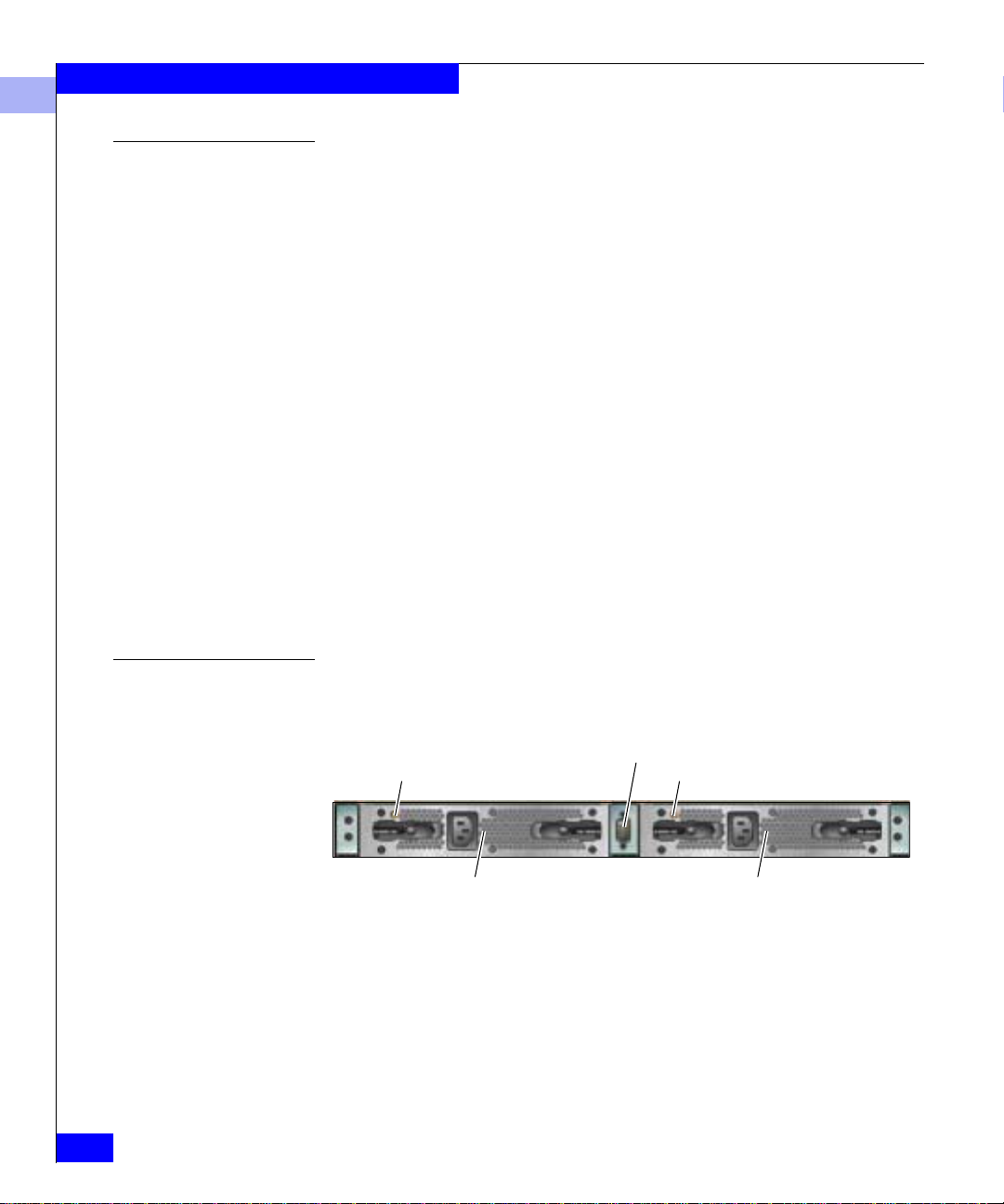
Figure 1-2 DS-24M2, Rear View
Connectrix DS-24M2 User Guide
Power Supply LED
Power Supply Module 1
Maintenance Port
Power Supply LED
Power Supply Module 0
Page 37

Switch Operating Features
Power Supplies The switch contains two power supply assembl ie s with internal
cooling fans. The redundant, load-sharing pow er supply assemblies
step down and rectify facility input power to provide 3.3 volts direct
current (VDC), 5 VDC, and 12 VDC to the control processor (CTP).
The power supplies also provide input filtering, overvoltage
protection, and overcurrent protection.
Either power supply can be replaced while the switch is operational.
Each power supply has a separate connection to the CTP card to
allow for independent AC power sources. The power supplies are
input rated at 90 to 264 volts alternating current (VAC).
Three cooling fans integrated in each power supply assemb ly (six
fans total) provide cooling for the power supplies and CTP, as well as
redundancy for continued operation if a single fan fails. Fans are
removed and replaced as part of the integrated power supply.
Maintenance Port The rear panel provides a 9-pin D-type subminiature maintenance
port that provi des a connection for a loc al terminal or dial-in
connection for a remote terminal.
The maintenance port is typically used by authorized maintenance
personnel, and can be used to configure switch network addresses,
such as the IP address, subnet mask, and gateway address.
1
DS-24M2 Descriptio n
1-7
Page 38

Switch Operating Features
1
Connectrix Service Processor
The Connectrix service processor is a notebook PC that provides a
central point of control for up to 48 LAN-connected Connectrix
Switches and/or Directors. The service processor is mounted inside
the front door of the EC-1200 cabinet.
Installation, configuration , and management of the switch requires
either a Connectrix service processor or Internet access to the
Embedded Web Server in the DS-24M2.
EMC recomm en d s us ing the Connectrix Manager to manage the swit ch .
The Connectrix service processor is dedicated to operation of the
Connectrix Manager and Product Manager applications, which
provide a graphical user interface (GUI) to monitor an d ma nage
Connectrix products. Refer to the Product Manager Overview on
page 3-2 for additional information about the Connectrix Manager
and Product Manager applicati o ns.
The Connectrix service processor and Connectrix Ma nager
application are a dedicated hardware and software solution that
should not be used for other tasks. EMC tests the Connectrix
Manager application installed on the Connectrix service processor,
but does not test other third-party software for compatibility .
Modifications to the Connectrix service processor hardware or
installation of additional software (including patches or service
packs) may interfere with normal operation.
Embedded Web Server
1-8
Connectrix DS-24M2 User Guide
Using a browser-capable PC with an internet connection to the
switch, you can monitor and manage the switch through the Web
Server interface embedded in the switch firmware. The interface
provides a GUI similar to the Product Manager application, and
supports switch configuration, statistics monitoring, and basic
operation.
Refer to Appendix C for detailed information on configuring the
switch from the Web Server.
.
Page 39

Hardware Features
Switch Operating Features
1
The DS-24M2 is an enterprise-class Fibre Channel switch that
provides high performance, high-availability conn ect ivity, and
enterprise-class manageability for an Open Systems environment.
The DS-24M2 provides 24 Fibre Channel G_Ports for attachment to
device N_Ports or NL_Ports, or switch E_Ports, through fiber-optic
links. The switches provide full-duplex, bidirectional data transfer at
1.0625 or 2.125 Gb/s for all ports.
Performance Features
The DS-24M2 provides these performance features:
◆ High bandwidth — Each port provides full-duplex serial data
transfer at a rate of up to 2.125 Gb/s.
◆ High-availability —The switch’s design provides a redundant
configuration of critical hardware components with automatic
failure detection and notification.
◆ Low latency — The latency is less than two microseconds
between transmission of a frame at a source port to receipt of a
frame at the corresponding destination port (with no port
contention).
◆ Low communication overhead — Fibre Channel protocol
provides efficient use of transmission bandwidth, reduces
interlocked handshakes across the communicatio n interface, and
efficiently implements low-level error recovery mechanisms. This
results in little communication overhead in the protocol and a
switch Bit Error Rate (BER) better than one bit error per trillion
-12
(10
) bits.
◆ Local control — Actions taking place at a device N_Port seldom
affect operation of other ports, therefore servers need to maintain
little or no information about other connected devices in a Storage
Area Network.
Hardware Features
1-9
Page 40

Switch Operating Features
1
Switch Management
Management access to the switch is provided through an Ethernet
LAN connection to the CTP subsystem. The following management
access methods are provided:
◆ Management through the Connectrix Manager and DS-24M2
Product Manager application — These Java-based GUIs reside on
the Connectrix service processor under control of the Microsoft
Win dows 2000 or Windows NT 4.0 operating system and can als o
be installed on remote user workstations. Re fer to Product
Manager Overview on page 3-2 for information about the
interfaces.
◆ Remote connection to the Connectrix service processor through
the local Connectrix Manager and Product Manager — This
allows up to nine concurrent users (eight remote use rs and one
local) to manage and monitor switches controlled by the
Connectrix service processor.
◆ Management us i ng SNMP — An SNMP agent is implemented
through the Product Manager application, allowing
administrators on SNMP management workstations to access
switch management information using any standard network
management tool. Administrators can assign IP addresses and
corresponding community names for up to six SNMP
workstations functioning as SNMP trap message recipients.
◆ Management through the Internet using the Embedded Web
Server in t e r face install e d o n t he switch — This interface supports
configuration, statistics monitoring, and basic operation of the
switch, but does not offer all the capabilities of the DS-24M2
Product Manager application. Admini strators launch the Web
Server from a remote PC by entering the switch’s IP address as
the URL, then entering a user name and password at a login
screen. The PC browser then becomes a management console.
1-10
Connectrix DS-24M2 User Guide
Page 41

Switch Operating Features
Figure 1-3 illustrates the switch management access methods.
Connectrix Manager Client Workstations
E-Mail Server
10/100 Mb/s
Corporate LAN
SNMP
Management
Station
Switch/Hub
Connectrix Manager Server
Running on
Connectrix Service Processor
1
Figure 1-3 Switch Management
High-Availability Features
Dual power supplies and spare unused ports ensure high availability.
◆ Power supplies — The switch has two power supplies that share
the electrical operating load. If one power supply fails, the other
supply handles the full load. Separate receptacles at the rear of
the switch provide facility input power to each supply. For full
redundancy, input power for each receptacle should come from a
different source.
◆ Concurrent firmware upgrade — The CTP subsystem p rovides
two nonvolatile memory regions. Because two firmware versions
can be stored in the CTP, firmware can be upgraded and activated
without disrupting switch operation.
Hardware Features
1-11
Page 42

Switch Operating Features
1
Connectivity Features
The DS-24M2 and the Product Manager applications support these
Fibre Channel connectivity features:
◆ Extended distance support — Through repeaters or Dense Wave
Division Multiplexing (DWDM) equipment, sw itch ports can be
configured for extended-distance operation. The DS-24M2's
maximum BB_credit value is 12, and only on ports 0 through 3.
Therefore, use port 0, 1, 2, or 3 for 10 km LW optics.
◆ Port blocking — System administrators can block or unblock any
switch port through the Product Manager application. Blocking a
port prevents an attached device from logging in to the switch or
communicating with any attached device. A blocked port
continuously transmits an offline sequence (OLS).
◆ Zoning — System administrators can partition attached d evices
into restricted-access zones. A zone contains a set of devices that
can access each other . A zone member can be a port or the WWN of
the device attached to a port. (EMC recommends that zones
contain only WWNs.) Ports and devices spread throughout
switches in a multiswitch fabric can be grouped into the same
zone.
Members of a zone can see each other, but members in different
zones cannot. HBAs with EMC-approved device drivers will
discover only those storage devices in their zone.
Security Features
1-12
Connectrix DS-24M2 User Guide
◆ State change notification — The DS-24M2 supports a state
change notification function that allows attached N_Ports to
request notification when other N_Ports change operational state.
The Connectrix Manager and Product Mana ger applications offer
these security features:
◆ Password protection — Users must provide a user name and
password to login to the Connectrix service processor and access
managed switches. Administrators can configure user names and
passwords for up to 16 users and can authoriz e or prohibit
management permissions for each user.
◆ Remote user rest rictions — Remote user access to the switches
can be either disabled or restricted to configured IP addresses.
◆ SNMP workstatio n restrictions — SNMP workstations can only
access MIB variables managed by the SNMP agent in the switch.
SNMP workstations must belong to SNMP communities
Page 43

Switch Operating Features
configured through the Product Manager application. If
configured, the agent can send authorization failure traps when
unauthorized SNMP workstations attempt to access the switch.
◆ Audit log tracking — Configuration changes to the switch are
recorded in an audit log stored on the Connectrix service
processor. Users can display the audit log through the Product
Manager application. Log entries include the date and time of the
configuration change , a descri ptio n of the cha nge , an d the source
of the change.
◆ Port blocking — System administrators can block or unblock any
switch port to restrict device access to the switch.
◆ E_Port/F_Port control function — The administrator can
configure the G_port for F_port operation only . If the port extends
the link outside the data center, this feature prevents the remote
user from connecting a switch and making the port an E_port.
◆ Zoning — System administrators can create zones that provide
switch access control to increase network security, differentiate
between operating systems, and prevent data loss or corruption.
Zoning can be implemented in conjunction with server-level
access control and storage device access control.
1
Serviceability Features
The Connectrix Manager and DS-24M2 Product Manager
applications offer these serviceability features:
◆ LEDs on FRUs and the front of the switch, provide visual
indicators of hardware status or malfunctions.
◆ System alerts, event logs, audit logs, link inci d ent logs, and
hardware logs that display switch, Ethernet link, and Fibre
Channel link status at the Connectrix service processor or a
remote work station.
◆ Diagnostic software that perform s power-on self tests (POSTs)
and port diagnostics (internal loopback, and external loopback
tests.)
◆ Automatic notification of significant system events (to support
personnel or administrators) through e-mail messages or the
call-home feature.
◆ An external modem for support personnel to dial in to the
Connectrix service processor for event notification and to perform
remote diagnostics.
Hardware Features
1-13
Page 44

Switch Operating Features
1
◆ An RS-232 maintenance port at the rear of the switch (port access
is password protected) that enables installation or service
personnel to:
• Change the switch’s MAC address, IP address, subnet mask,
and gateway address.
• Enable or disable the LAN data rate auto-negotiate feature.
The default is enabled.
• Set Fibre Channel port operation to half duplex or full duplex.
The default is full-duplex operation.
◆ Redundant FRUs (SFP LC transceivers and power supplies) that
can be removed or replaced without disrupting switch or Fibre
Channel link operation.
◆ A modular design that enables quick removal and replacement of
FRUs without tools.
◆ Concurrent port maintenance. SFP transceivers can be added or
replaced, and fiber optic cables can be attached to ports without
interrupting other ports or switch operation.
◆ Beaconing to assist service personnel in locating a specific port or
switch. When port beaconing is enabled, the am ber LED
associated with the port flashes. When unit beaconing is enabled,
the system error indicator on the front bezel flashes. Beaconing
does not affect port or switch operation.
◆ SNMP management using the Fibre Alliance MIB that runs on the
Connectrix service processor. Up to 12 authorized management
workstations can be co nfigured through the Connectrix Manager
application to receive unsolicited SNMP trap messages. The trap
messages indicate operational state changes and failure
conditions.
1-14
◆ SNMP management using the Fibre Channel Fabric Element MIB
(Version 2.0), TCP/IP MIB-II defini tio n ( RF C 1213), or a DS-24M2
MIB that runs on each switch. Up to six authorized management
workstations can be configured through the Product Manag er
application to receive unsolicited SNMP trap messages. The trap
messages indicate operational state changes and failure
conditions.
◆ Data collection through the Product Manager applica tion to help
isolate system problems. The data includes a memory dump file
and audit, hardware, and engineering logs.
Connectrix DS-24M2 User Guide
Page 45

Hardware Operations
This section introduces hardware operations that affect the DS-24M2.
Switch Operating Features
1
Updating Firmware
Switch Operational States
The Connectrix service processor’s fixed disk can contain a library of
firmware versions for downloading to any DS-24M2 managed by the
Connectrix service processor. Refer to Managing Firmware Versions on
page 7-7 for instructions on changing switch firmware.
Because the CTP contains two nonvolatile memory regions, firmware
can be loaded (sent) to the switch without disrupting port operation.
The switch can have one of the following operational states:
◆ On line — When the switch is in the online state, all o f the
unblocked ports are allowed to log in to the fabric and begi n
communicating. Devices can connect to the switch if the port is
not blocked and can communicate with another attached device if
both devices are in the same zone or if the default zone is enabled.
◆ Off line — When the switch is in the offline state, all the installed
ports are off line. The ports transmit OL S and cannot accept a
login for connection from an attached device. All port s in the
switch, including E_Ports, are placed off line, regardless of
whether they were blocked or unblocked, and the switch is
removed from a multiswitch fabric.
The operational state of the switch can be changed from the Product
Manager through the Set Online State option. Refer to Setting th e
Online State on page 7-6 for details.
Hardware Operations
1-15
Page 46

Switch Operating Features
1
IML
When the IML button is pressed and held for three seconds, the
switch performs an Initial Machine Load (IML) that takes about 30
seconds. This operation:
◆ Resets the microprocessor and functional logic for the CTP and
loads firmware from flash memory.
◆ Resets ports (including failed ports) (which causes all Fibre
Channel connectors to drop momentarily until the con nections
automatically recover).
◆ Resets the Ethernet interface on the CTP, causing the connection
to the Connectrix service processor to drop momentarily. The
alert symbol on the Product View on the Connectrix Manager
changes to a gray square until the connection is re-established.
◆ Automatically enables changes made to the active zone set if
these changes were not enabled before the IML.
◆ Keeps all fabric services databases intact, making th e operation
transparent to attached devices. These databases contain such
information as current fabric logins, name server registrations,
and other data.
◆ A reset causes the link between the DS-24M2 and the Connectrix
service processor to drop momentarily. The following occurs in
the Product Manager wind ow:
• As the network connection drops, the status table on the
Hardware view turns yellow.
• The Status field in the table displays
No Link and the State
field displays the reason why the link did not occur.
• The Link Loss Status table appears.
• A gray square appears in the alert panel.
• The FRUs illustrated in the Hardware view disappear, and
then reappear as the connection is re-established.
1-16
Connectrix DS-24M2 User Guide
Page 47

IPL
Switch Operating Features
1
!
CAUTION
An IPL is not intended for ordinary or casual use and should be
performed only if the active CTP is suspect or if directed by
next-level support or documentation. An IPL interrupts the link
between the Connectrix service processor and switch.
T o perform an IPL (Initial Program Load), select IPL from the Product
Manager Maintenance menu. The IPL functions like an IML, except
that an IPL:
◆ Restarts the operational firmware on the CTP, executes
abbreviated power on self tests (POSTs) and then, if no POST
errors are encountered, resumes the active role that it had before
the IPL.
◆ Resets the Ethernet interface on the CTP subsystem, causin g the
connection to the Connectrix service processor to drop
momentarily. The status icon for the switch in the Product View
will change to a gray square until the connection is reestablished.
◆ Stops normal switching functions for ports. (Functions resume
after the IPL.)
After the IPL:
◆ All fabric services databases containing information about
current Fabric logins, name server registrations, and other data
remain intact, making the operation transparent to attached
devices.
◆ The switch returns to the online state, even if it was off line before
the operation.
◆ All ports configured as blocked will remain blocked.
Hardware Operations
1-17
Page 48

Switch Operating Features
1
1-18
Connectrix DS-24M2 User Guide
Page 49

Invisible Body Tag
2
Operating the Switch
This chapter describes the operation of the DS-24M2 and identifies
the controls and indicators.
◆ Power Procedures ..............................................................................2-2
◆ FRU LEDs and Connectors...............................................................2-4
Operating the Switch
2-1
Page 50

Operating the Switch
C
r
2
Power Procedures
Power the Switch On
The DS-24M2 has no AC power switches. To power the switch on,
plug either AC power cord (shown in Figure 2-1) into an AC power
source.
onnecto
Figure 2-1 AC Power Cords
Connector
Power-On Self-Tests When the unit is po wer e d on, power-on self tests (POSTs) run to ensure
correct operation of switch logic. These tests reside in flash memory
on the Control Processor (CTP). They verify correct operation of the
CTP, ports, LEDs, and other hardware components.
During POSTs, several tests occur in sequence. As they occur:
1. The green power (PWR) LED on the front panel illuminates.
2. The amber system error (ERR) LED on the front panel blinks
momentarily while the switch is tested.
3. The green LEDs at the top of the Ethernet connector blink while
the port is tested.
4. The green/blue and amber LEDs associated with Fibre Channel
ports blink momentarily while the ports are tested.
After successful POSTs, the green power LED remains illuminated
and all other front panel LEDs go dark. If any of the following occurs,
contact EMC Customer Support:
◆ The amber system error LED remains on.
◆ The green power LED is off.
2-2
Connectrix DS-24M2 User Guide
Page 51

Operating t h e Switch
◆ The amber LED for either power supply on the rear of the unit is
on (and the power cord on that power supply is plugged into a
working AC power source).
2
Powering the Switch
Off
!
You do not need to power the switch off to remove FRUs or to
connect fiber-optic cables to and from ports. However, you must
switch off the power to relocate the switch.
Powering the switch off and on (power cycle) resets all hardware
components and interrupts port operation. When powering the unit on, all logic
is reset.
Follow these steps to power the switch off:
CAUTION
Warn administrators and users currently operati ng devices tha t are
attached to the switch that it is going off line and that
communications will be disrupted. Also, request that the devices
affected by an interruption of data flow be set off line.
1. Set the switch off line using the Set Online State option from the
Product Manager (refer to the above warning before setting the
switch off line).
2. Disconnect the power cord for each power supply from its AC
source.
Power Procedures
2-3
Page 52

Operating the Switch
2
FRU LEDs and Connectors
LEDs
LEDs on hardware components indicate operational status. Figure
2-2 and Figure 2-3 show LED locations and Table 2-1 describes their
functions.
Power LED
Error LED
Figure 2-2 Front Panel LEDs and Connectors
Figure 2-3 Rear Panel LEDs and Connectors
IML Button
Ethernet Connector
Maintenance Port
Power Supply LED
Power Supply Module 1
SFP Transceivers (24)
Power Supply LED
Power Supply Module 0
Port LEDs
2-4
Connectrix DS-24M2 User Guide
Page 53

Table 2-1 LEDs
LED Color State Function
Power Green On The switch is receiving power.
Operating t h e Switch
2
Off The switch may not be receiving AC power. Check the
AC power source and power cords.
Error Amber On The switch has detected an event requiring immediate
operator attention, such as a FRU failure. The LED
remains illuminated as long as an event is active.
Off Someone has selected Clear System Error Light
from the Product Manager application.
Blinking Unit beaconing is enabled (and there is no error; even
if beaconing is enabled, the LED will illuminate
continously if there is a failure).
Ethernet
Connector
Port Green/
Green See
Function
On The port is connected with the attached end device
Blue
Two LEDs at the top of the Ethernet connector
indicate LAN speed:
◆ Left LED on = 10 Mbps
◆ Right LED on = 100 Mbps
and is ready to communicate. The LED illuminates in
green to indicate 1.0625 Gb/s port operation and blue
to indicate 2.125 Gb/s operation.
Off The port is off line.
Blinking There is active Fibre Channel traffic on the port.
Amber On The port has failed.
Off The port is operational.
Blinking The port is running diagnostics or port beaconing has
been enabled from the Product Manager. (Refer to
Port Operational States on page 4-35.)
Power
Supply
Amber On The power supply has failed or has lost AC power.
Off The power supply is operational.
FRU LEDs and Connectors
2-5
Page 54

Operating the Switch
2
Connectors
The DS-24M2 contains a variety of connectors used to connect the
switch to the Connectrix service processor, customer LAN, and
attached devices. Figure 2-1 on page 2-2 and Figure 2-2 on page 2-4
show connector location s, and Table 2-2 describes their functions.
Table 2-2 Connectors
Connector Function
RJ-45 100Base-T
Ethernet
Port Connects the switch to user devices and other switches.
AC power Supplies AC power to the two supplies, providing single-phase
Connects the switch to the same 100 Mbps LAN as the Connectrix
service processor. All data to and from the switch and Connectrix
service processor is transported on this link.
connections with input rated up to 264 VAC.
2-6
Connectrix DS-24M2 User Guide
Page 55

Invisible Body Tag
3
Product Manager
Overview
This chapter is an introduction and overview of the DS-24M2 Product
Manager application. It is intended as a quick reference for using
features available through the main Product Manager window.
◆ Product Manager Overview.............................................................3-2
◆ Using the Product Manager..............................................................3-5
◆ Product Manager Menu Bar...........................................................3-12
◆ Product Manager Views..................................................................3-17
◆ User Rights.......................................................... ...... ........................3-21
Product Manager Overview
3-1
Page 56

Product Manager Overview
3
Product Manager Overview
The Product Manager fo r t he DS-2 4M2 is a Java-based graphical user
interface (GUI) that provides in-depth management, confi gura tion,
and monitoring functions for individual switches and their
field-replaceable units (FRUs). Although each Product Manager is
accessed from the Connectrix Manager, it is a separate application.
In contrast to the Product Manager, the Connectrix Manager enables
administrators to monitor operational status for all products and
Fibre Channel fabrics managed by a Connectrix service processor.
The Connectrix Manager also provides tools to administer user and
product access to the Connectrix Manager and Product Manager.
(Refer to the Connectrix Manager User Guide.)
The Product Manager provides graphical views of switch ha rdware
components and component status. By positioning the cursor on
icons, graphics, panels, and other visual elemen ts in these views and
clicking the mouse/touchpad, y ou can quickly manage and monitor
the switch on your network.
Using the Product Manager, you can:
3-2
◆ Back up and restore configuration data.
◆ Clear the system error indicator.
◆ Configure extended distance buffering for ports.
◆ Configure Fibre Channel operating parameters for the switch.
◆ Configure individual ports with a port name describing the node
attached to the port.
◆ Configure link incident (LIN) alerts.
◆ Configure port binding (if the Port Binding feature is enabled).
◆ Configure Nicknames to display instead of WWNs for switches
and attach ed devices.
◆ Configure SNMP trap recipients and community names.
◆ Configure Open Systems Management Server features (if
installed).
◆ Configure switch binding if optional Enterprise Fabric Extensions
feature is installed.
◆ Configure an interoperability mode for multiswitch fabrics.
Connectrix DS-24M2 User Guide
Page 57

Product Manager Overview
◆ Configure the switch name, location, description, and contact
person.
◆ Configure threshold alerts for ports.
◆ Enable LIN alerts on ports.
◆ Control individual Fibre Channel ports by blocking/unblocking
operation, enabling LIN alerts, enabling port binding, and setting
data speeds.
◆ Display FRU properties such as the FRU name, physical position
in the switch, active failed state, part number, and serial number.
◆ Display information for individua l Fibre Channel ports, such as
the port name, port number, Fibre Channel address, operational
state, type of port, and login data.
◆ Display information on nodes attached to ports.
◆ Display port performance and statistics.
◆ Display product data for the switch, such as the system name,
description, contact person, location, status, model number,
firmware and Engineering Change (EC) level, and manufacturer.
◆ Enable beaconing for ports and the switch.
3
◆ Monitor the operational status of the switch and each of its
hardware field-replaceable units.
◆ Perform an Initial Program Load (IPL).
◆ Perform maintenance tasks for the switch, incl ud ing maintaining
firmware levels, administering the call -home feature, accessing the
switch logs, and collecting data to support failure analysis.
◆ Reset port operation.
◆ Run port diagnostics.
◆ Set the date and time on the switch.
Access the switch Product Manager by double-clicking a switch
Product icon on the Connectrix Manager window (in either the
Products view or the Fabrics view).
You ca n install the Connectrix Manager Client application onto a
remote workstation using any standard Web browser. For
instructions on installing the Client, refer to the appendix titled
Configuring Remote Workstations in the Connectrix Manager User Guide.
Product Manager Overview
3-3
Page 58
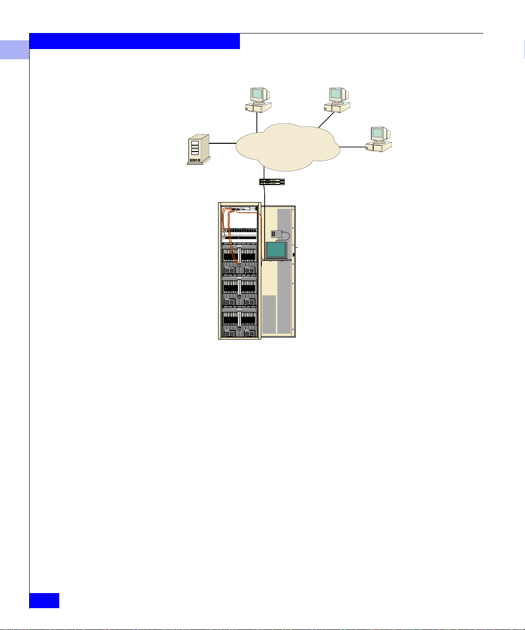
Product Manager Overview
3
Connectrix Manager Client Workstations
E-Mail Server
10/100 Mb/s
Corporate LAN
Switch/Hub
Connectrix Manager Server
Running on
Connectrix Service Processor
SNMP
Management
Station
3-4
Figure 3-1 Connectrix Service Processor and Remote Workstation Configuration
Connectrix DS-24M2 User Guide
Page 59

Using the Product Manager
This section provides a general overview of the Connectrix Manager
and its functions. For details on performing specific tasks and using
specific dialog boxes, refer to the appropriate chapters in this manual.
Product Manager Overview
3
Using Dialog Boxes
Figure 3-2 Typical Dialog Box
Dialog boxes, such as the one in Figure 3-2, appear when you select
options from the pop-up me nus.
The terms dialog box and window are sometimes used interchangeably.
To enter d ata into an empty field, click in the field and begin typing
when the cursor appears at insertion point.
To change or remove data that already exists in a field, drag the
cursor (or double-click on the data) to highlight the cha r acters you
want to change/delete; then type in the new data. (It should
overwrite the highlighted characters; if not, use the
BACKSPACE key to remove characters.
DELETE or
Clicking one of these buttons in a dialog box initiates the described
function (not all buttons appear in all dialog boxes):
◆ OK — Saves the data you entered and closes the dialog box.
◆ Activate — Saves the data you entered and closes the dialog box,
unless there is a Close button, in whi c h c as e Activate saves the
information without closing the box.
◆ Close — Closes the dialog box and saves the data you entered.
◆ Cancel — Cancels the operation and closes the dialog box
without saving the information you entered.
Using the Product Manager
3-5
Page 60

Product Manager Overview
3
Keyboard Navigat ion Keyboard navigation is an alternative to mouse navigation. Use the
methods described in this section to naviga te using your keyboard.
Logging Int o t he Connectrix Manager
To open the Product Manager, you must first log into the Connectrix
Manager:
1. The Connectrix Manager starts automatically when the
Connectrix service processor is powered on or rebooted.
If you need to start the Client application on a remote
workstation, follow the appropriate steps:
OS Steps
Windows
a
a. If necessary, switch the Connectrix service processor on.
b. On the Windows desktop,
double-click the
Connectrix Manager icon:
Solaris or
Linux
a. In the Terminal window, type the following and press
b
ENTER:
[root@evtcom2 /root]# cd /home
b. Type [root@evtcom2 /root]# cd EFCM and
press
ENTER.
c. Type
[root@evtcom2 /root]# ./ConnectrixManager
and press
ENTER.
3-6
HP/UX or
AIX
Connectrix DS-24M2 User Guide
a. In the Terminal window, type the following and press
b
ENTER:
[root@evtcom2 /root]# cd /home
b. Type [root@evtcom2 /root]# cd EFCM and
press
ENTER.
c. Type
a. Windows 95, Windows 98, Windows NT, or Windows 2000.
b. These steps assume the Connectrix Manager is in your home directory. If you
saved it to a different location, enter the appropriate directory names.
[root@evtcom2 /root]# ConnectrixManager
and press
ENTER.
Page 61
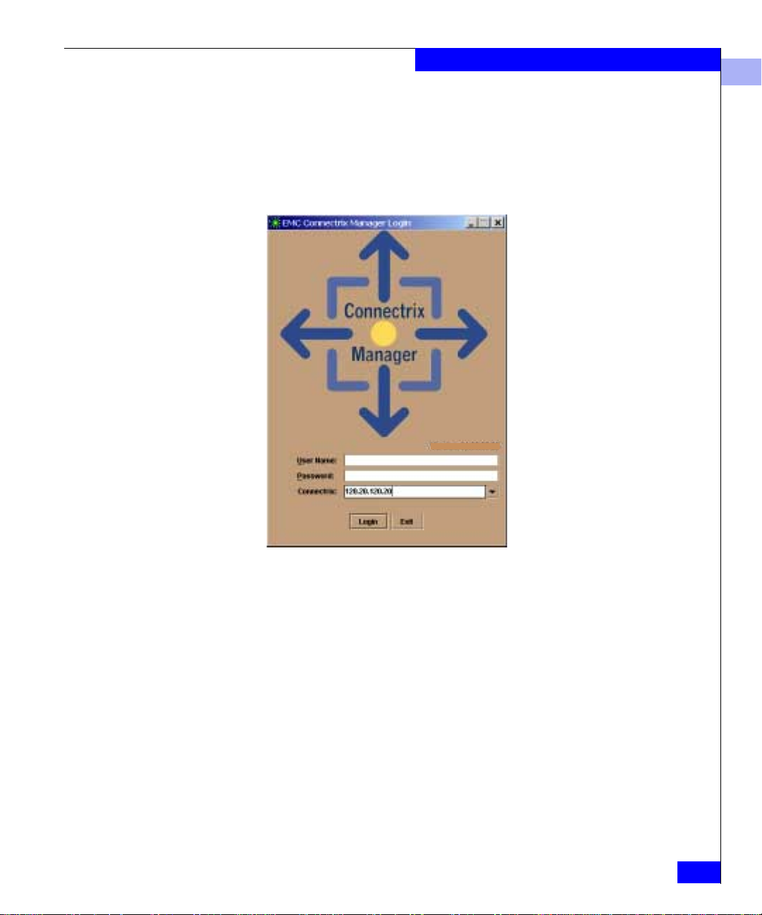
Product Manager Overview
2. On the Connectrix Manager Login window (Figure 3-3), enter
your user name and password. (U ser names and passwords are
case-sensitive. )
If user names have not been established, use the default user
name (Administrator) and password (password).
Version: 06.03.00.x
3
Figure 3-3 Connectrix Manager Login Window
3. The default address that appears in the Connectrix field is the
address of the last service processor or server accessed. Click the
arrow to the right of the field display the network addresses of all
Connectrix service processors that were accessed from your
PC/workstation.
Select an address or, if you want to connect to a Connectrix
service processor that is not listed, enter the name or IP address.
4. Click Login.
If the connection is successful, the Connectrix Manager opens to
the Products view (Figure 3-4). (The other main view is the
Fabrics view, which is described in the Connectrix Manager User
Guide.)
Using the Product Manager
3-7
Page 62
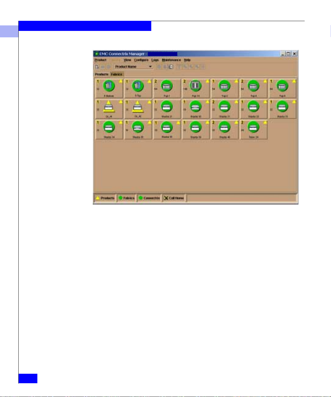
Product Manager Overview
3
110.22.140.78
3-8
Figure 3-4 Connectrix Manager Products View
The Products view provides a graphical overview of all the products
that can be managed and monitored through the Connectrix
Manager. In a full-screen environment on an 800 x 600 resolution
monitor, this panel displays up to 48 product icons.
Connectrix DS-24M2 User Guide
Page 63
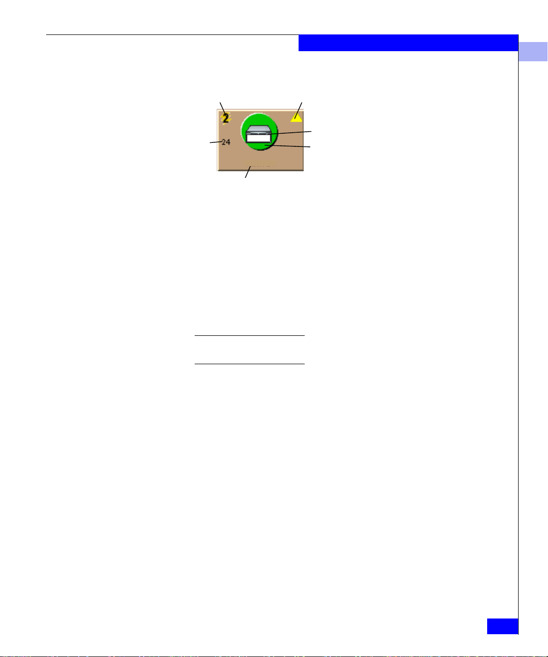
Product Manager Overview
Product Icons Information in each product icon in clud es the following:
Switch Speed (Gb/s) Attention Indicator
Product Illustration
Number
of Ports
MySwitch 5
Product Name or Network Address
Status Indicator
Object descriptions:
◆ Switch data speed: 2 Gb/s.
◆ Attention indicator — A yellow triangle means that product
requires attention. Open the Product Manager application for the
director by double-clicking on the icon to find out more
information.
◆ Product name or network address — You can determine which
appears by right-clickin g on the open ar ea away from the pro duct
icons and selecting Display Options from the pop-up menu.
3
Whichever identifier appears, you can display a pop-up window with
the other identifier by moving the cursor over the product icon.
◆ Status indicator (the color-coded symbol behind the product
illustration):
• A red and yellow diamond means that the product has failed
and requires immediate service.
• A yellow triangle means that the product is degraded, but is
still performing as designed.
• A green circle means that the product is fully operational.
• A grey square means that the Connectrix Manager cannot
determine product status.
• If an alert symbol does not display behind the product, the
product is not managed by the Connectrix service processor to
which you are logged in.
The most critical status reflected by a product in the view is also
reflected in the Products status box in the left corner of the
Connectrix Manager window.
Using the Product Manager
3-9
Page 64

Product Manager Overview
3
Opening the Product Manager
Windows Title Bar
Menu Bar
View Selector
You can open the Product Manager for a product in any of these
ways:
◆ Double-click the product icon in the Connectrix Manager
window, in either the Products or Fabrics view
◆ Right-click the product icon, and select Open on the pop-up
menu.
◆ Click the product icon to highlight it; then press CTRL-O or click
the Open Product icon on the Connectrix Manager toolbar:
Open
Product
120.20.150.10
The Product Manager opens to the Hardware view (Figure 3-5).
ABC 123
ABC 123
3-10
Main Panel
Status Indicator
Figure 3-5 Product Manager Window
Connectrix DS-24M2 User Guide
Page 65

Product Manager Overview
The Connectrix Manager window is still avail able a s a separate window. You
can drag the Product Manager window away from the Connectrix Manager
window and view both windows on your PC desktop (or minimize one or
both to icons if desired). You can have up to four Product Manager windows
open concurrently.
For more information on the Products view, refer to these sections:
◆ Product Manager Menu Bar on page 3-12
◆ Product Manager Views on page 3-17
3
Closing the Product Manager
Closing the Connectrix Manager
To close the Product Manager, select Close from the Product menu.
To log out of the Connectrix Manager (so you can log in again using a
diferent user name a nd password), s elect Logout from the Connectrix
Manager Product menu.
To close the Connectrix Manager application, select Exit from t h e
Connectrix Manager Product menu.
Using the Product Manager
3-11
Page 66

Product Manager Overview
3
Product Manager Menu Bar
Menu Bar
Figure 3-6 Product Manager Menu Bar
DS-24M2: ABC123
DS-24M2 Status
The menu bar consists of these menus:
◆ Product:
• Port — Contains the following items; refer to Port Menu on
page 4-15 for descriptions:
– Port Properties
– Port Technology
– Block Port
– Enable Beaconing
– Port Diagnostics
– Clear Link Incident Alert(s)
– Reset Port
– Port Binding
– Clear Threshold Alert(s)
• FRU — Contains a FRU Properties entry; refer to Displaying
FRU Properties on page 4-9 for a description.
• Clear System Error Light — Turns off the amber system error
LED, located below the power LED on the front of the switch.
• Enable Unit Beaconing — Causes a system error light on the
front of the switch to blink, to help users locate the actual unit
in an equipment room. (Yo u can enable unit beaconing only if
the system error light is off, signifying that there are no
outstanding errors.)
• Properties — Displays such information as the switch name,
description, location, and contact person. Refer to Displaying
Switch Properties on page 4-13.
• Close — Closes the Product Manager window.
ABC 123
3-12
Connectrix DS-24M2 User Guide
Page 67

Product Manager Overview
◆ Configure:
• Identification — Allow s you to specify information that will
appear in the identification table at the top of the Hardware
view and in the Connectrix Manager Products view (if the
Products view is configured to display names)
Refer to Configuring Switch Identification on page 5-2.
• Operating Parameters — Allows you to set the following
operating parameters (described in greater detail under
Configuring Operating Parame te rs on page 5-4):
3
Switch
Preferred Domain ID
Parameters
Insistent
Rerouting Delay
Domain RSCNs
Suppress RSCNs on zone set activations
Fabric
Parameters
R_A_TOV
E_D_TOV
Switch Priority
Interop Mode (Homogeneous Fabric or
Open Fabric 1.0)
The DS-24M2 does not support configurable BB_Credits
(buffer-to-buffer credits):
– Ports 0 through 3 are set to 12 BB_Credits each.
– Ports 4 through 23 are set t o 5 BB_Credits each.
• Switch Binding — allows you to activate switch binding
according to a specific connection policy., and to create a list of
switches and devices that you want to allow exclusively to
attach to switch ports.
Switch Binding is an optional feature that you can enable
through the Configure Feature Key dialog box. For details,
refer to Configuring Switch Binding on page 5-12.
This function is available only if Enterprise Fabric Extensions
is installed.
Product Manager Menu Bar
3-13
Page 68

Product Manager Overview
3
• Ports — Allows you to configure a port name, block or
unblock operation, configure LIN alerts, enable Fabric
Address Notification, define a Fibre Channel port type, set the
port speed, enable port binding, and specify a bound WWN.
Refer to Configuring Ports on page 5-18.
• SNMP Agent — Allows you to configure network addresses
and community names for up to six SNMP trap recipients.
Refer to Configuring the SNMP Agent on page 5-24.
• Management Server — Allows you to configure the open
systems inband management program to function with the
switch. (The Open Systems Management Server feature must
be installed in order to perform this procedure.)
Refer to Configuring Management Server Control on page 5-27.
• Features — Allows you to validate an installed feature for use.
Refer to Configuring Feature Keys on page 5-28.
• Date/Time — Allows you to set the date and time on the
switch, and to set the switch to synchronize with the date and
time on the Connectrix service processor.
Refer to Configuring the Date and Time on page 5-31.
3-14
• Threshold Ale rts — Allows you to configure threshold alerts
for ports. A threshold alert notifies users when the transmit
(Tx) or receive (Rx) throughput reaches specified values for
specific director ports or port types (E_Port, F_Port, FL_Port).
Refer to Configuring Threshold Alerts on page 5-33.
• Export Configuration Report — Allows you to save an ASCII
text file containing all current user-definable configuration
options in a printable format.
Refer to Exporting a Configuration Report on page 5-41.
• Enable Web Server — Allows you to to enable the Embedded
Web Server interface on the switch.
Refer to Enabling the Embedded Web Server on page 5-43.
• Enable Telnet — Allows you to enable Telnet access to the
switch.
Refer to Enabling Telnet on page 5-44.
Connectrix DS-24M2 User Guide
Page 69

Product Manager Overview
◆ Logs:
• Audit Log — Provides a record of all configuration changes
made on the switch. Refer to Audit Log on page 6-4.
• Event Log — Provides a record of significant events that have
occurred on the director, such as hardware failures, degraded
operation, and port problems. Refer to Event Log on page 6-6.
• Hardware Log — Displays information on FRUs inserted and
removed from the switch. Refer to Hardware Log on page 6-8.
• Link Incident Log — Displays the most recent incidents with
their date and time, port number, and description of the
incident.
Refer to Link Incident Log on page 6-9.
• Threshold Alert Log — Provides notifications of threshold
alerts, including date and time each alert occurred, port for
which the alert is configured, and type of alert (transmit
throughput, receive throughput, or both).
Refer to Threshold Alert Log on page 6-11.
◆ Maintenance:
3
• Port Diagnostics — Is used by service personnel to run
internal and external loopback tests on ports.
• Data Collection — Allows you to collect maintenance data
into a file. This file is used by support personnel to diagno se
system problems. Refer to Collecting Maintenance Data on
page 7-3.
• IPL — Allows you to initiate an Initial Program Load on th e
switch Refer to Executing an IPL on page 7-4.
• Set Online State — Allows you to change the online state of
the switch to off line or on line. Refer to Setting the Online State
on page 7-6.
• Firmware Library — Displays all firmware versions currently
installed on the Connectrix service processor that can be
downloaded to the switch. Refer to Managing Firmware
Versions on page 7-7.
• Enable E-Mail Notification — Allows you to enable e-mail
notification for the switch. Refer to Enabling E-Mail Notification
on page 7-8.
Product Manager Menu Bar
3-15
Page 70

Product Manager Overview
3
• Enable Call Home Notification — Allows you to enable the
call-home function for the switch. Refer to Enabling Call-Home
Notification on page 7-9.
• Backup & Restore Configuration — Allows you to save the
product configuration stored on the switch to the Connectrix
service processor hard disk or to restore the product
configuration from the Connectrix service processor (to a
switch with the same IP address as the one that was backed
up). Refer to Backing Up and Restoring the Configu rat ion on
page 7-10.
• Reset Configuration — Allows you to reset all switch
configuration data back to the factory defaults. Refer to
Resetting the Configuration on page 7-16.
◆ Help:
• Contents — Displays online help for the Product Manager.
• About — Displays the version number for the Product
Manager and copyright information.
3-16
Connectrix DS-24M2 User Guide
Page 71

Product Manager Views
Product Manager Overview
3
DS-24M2: ABC123
Figure 3-7 Product Manager View Selector Tabs
Hardware View
View Tabs
DS-24M2 Status
ABC 123
The Product Manager offers four main views, accessible by clicking
the tabs.
The Hardware view (Figure 3-8) is the default view that appears in
the main panel when you open the Product Manager.
For details on navigating and monitoring via the Ha rdware view,
refer to Chapter 4.
DS-24M2 : ABC 123
ABC 123
Figure 3-8 Product Manager Hardware View
Product Manager Views
3-17
Page 72

Product Manager Overview
3
In the Hardware view, color-coded indicators reflect the status of
actual LEDs on the switch FRUs. The status indicator at the lower left
displays a symbol to represent the most degraded status currently
reported by any of the switch FRUs. For example, for a port failure,
indicated by a red and yellow diamond on a port, a yellow triangle
appears on the alert panel to indicate a degraded condition.
For an explanation of the various alert symbols, refer to Table 4-1 on
page 4-5.
Displaying Properties
and Options
Port Li st Vi e w
Double-clicking anywhere on the switch except on a FRU d isplays a
Switch Properties window. Double-clicking on the power supply or
cooling fan module displays a FR U Properties window containing
detailed information on the hardware component.
Right-clicking anywhere on the switch except on a FRU displays a list
of options for the switc h. Refer to Using Menu Options on page 4-14
for more information.
For reference, here are the menu options:
◆ Switch Properties
◆ Enable Unit Beaconing
◆ Clear System Error Light
◆ IPL Switch
◆ Set Switch Date and Time
◆ Set Switch Online State
Clicking the Port List tab on the Product Manager window (refer to
Figure 3-7 on page 3-17) displays a table listing:
◆ # — Port number
◆ Name — Port name
3-18
◆ Block Confi g — Blocked/unblocked configuration
◆ State — Operating state
◆ Type — Port type
◆ Operating speed
◆ Alert — Identification of any ports with outstanding aler t
conditions
Connectrix DS-24M2 User Guide
Page 73

Product Manager Overview
Other options available on the Port List vi ew allow you to:
◆ Block/unblock ports
◆ Display port properties
◆ Display port technology: connector and transceiver types,
distance, media, and speed
◆ Configure port binding
◆ Run port diagnostics
◆ Enable port beaconing
◆ Clear Link Incident Alert(s)
◆ Clear Threshold Alert(s)
◆ Reset the port
For details on these menu options, refer to Port Menu on page 4-15.
For details on navigating and monitoring using the Port List view,
refer to Using the Perfo rmance View on page 4-25.
3
Node List View
Clicking the Node List tab on the Product Manager window (refer to
Figure 3-7 on page 3-17) displays a table of informa tion about all
node attachments or N_Ports tha t have logged into existing F_Ports
on the switch. Only N_Ports appear in the Node List view after nodes
have logged in to the fabric.
The columns that appear in the table include:
◆ Port — Port number where the node is attached
◆ Address — Fibre Channel address of the node
◆ Node Type :
• N_Port — The switch port is operating as an F_Port
• NL_Port — The switch port is operating as an FL_Port
◆ Port WWN — WWN of the attached node (device)
◆ Unit Type — Type of connected device
◆ BB_Credit — Value used by the attached node
For details on navigating and monitoring via the Node List view,
refer to Using the Node List View on page 4-21.
Product Manager Views
3-19
Page 74

Product Manager Overview
3
Performance View
FRU List View
Clicking the Performance tab on the Product Manager window (refer
to Figure 3-7 on page 3-17) displays a graphical display of
performance for all ports. (Figur e 4-7 on page 4-25 shows an example
of the Performance view. )
The top portion of the Performance view displays bar graphs that
show the level of transmit/receive activity for each port. This
information is updated every five seconds. Each bar graph also
shows the percentage link utilization for the port.
The bottom portion of the Performance view displays cumulative
statistical information for the port selected in th e bar graph. Values
are displayed for transmit and receive traffic, class 2 and 3 statistics,
operational statistics, and error categories.
For more in formation about the Performance view, refer to Using the
Performance View on page 4-25.
Clicking the FRU List tab on the Product Manager window (shown in
Figure 3-7 on page 3-17) displays a table with information about each
of the FRUs installed in the switch. All d ata is dynamic and is
updated automatically .
Figure 4-9 on page 4-33 shows an example of the FRU List view. For
details on navigating and monitoring via the FRU List view, refer to
Using the FRU List View on page 4-33.
3-20
Connectrix DS-24M2 User Guide
Page 75

User Rights
Product Manager Overview
3
The Connectrix Manager’s system administrator can assign levels of
access, or user rights, to Product Manager users through the
Connectrix Manager application.
Note that the Connectrix Manager’s system administrator only has view
rights while operating in a specifi c Pro duct Manager appl ication. Conversely,
a Product Manager’s product administrator only has view rights while
operating in the Connectrix Manager application.
Detailed instructions concerning the ass ignment of user rights for
both the Connectrix Manager and Product Manager appl ications
appear in the Co nnectrix Manager User Guide.
Any of these levels of user rights can be assigned to specific users:
◆ System Administrator
◆ Product Administrator
◆ Operator
◆ Maintenance
◆ View
By default, all users have View rights, which allow viewing
configurations, but not changing them. View rights cannot be
removed.
Users with System Administrator rights can make all control and
configuration changes implemented through the Connectrix Manager
application.
User Rights
3-21
Page 76

Product Manager Overview
3
User Rights for Specific Functions
Table 3-1 User Rights for Product Manager Functions
T able 3-1 item izes the specific functions available to Product Manager
users that have been assigned user rights of Product Administrator,
Operator, and/or Maintenance. If a user does not have the right to
perform a specific operation, a
not authorized error box appears
when the operation is attempted.
Product Manager Rights
Backup/Restore Configuration X X
Block Port X X X
Change Online State X X
Clear Audit Log X
Clear Audit Log X
Clear Event Log X
Clear Hardware Log X X
Clear LIN Alert X X
Clear LIN Log X
Product
Administrator Operator Maintenance
3-22
Clear System Error Light X
Configure Date/Time X X X
Configure Feature Key X
Configure Identification X
Configure Management Server X
Configure Switch Parameters X
Configure Fabric Parameters X
Configure Port Binding X X
Configure Ports X X
Configure SNMP X
Configure Switch Binding X
Configure Zoning X
Connectrix DS-24M2 User Guide
Page 77

Product Manager Overview
Table 3-1 User Rights for Product Manager Functions (continued)
Product
Product Manager Rights
Administrator Operator Maintenance
Data Collection X
Date/Time Sync Configuration X X X
Enable Call Home Notification X
Enable E-Mail Notification X
Export Configuration Report X X X
IPL X X
Manage Firmware X
Port Diagnostics X
Port Beaconing X X X
Set Online State X X X
Reset Configuration X
3
Reset Statistics Counters
XX
(Performance View)
Reset Port X
Unit Beaconing X X X
View Event Log X X
View Firmware X
View Hardware Log X X X
View LIN Log X X X
View SNMP X X
View Threshold Alert Log X X X
User Rights
3-23
Page 78

Product Manager Overview
3
3-24
Connectrix DS-24M2 User Guide
Page 79

Invisible Body Tag
4
Monitoring and
Managing the Switch
This chapter describes how to use the features available in the various
Product Manager views to monitor and mana ge switch operation.
The views are accessible from the tabs shown here:
DS-24M2: ABC123
View Tabs
◆ Using the Hardware View................................................................4-2
◆ Using the Port List View ................................................................. 4-17
◆ Using the Node List View...............................................................4-21
◆ Using the Performance View..........................................................4-25
◆ Using the FRU List View.................................................................4-33
◆ Port Operational States ........................................... ........................4-35
◆ Alerts..................................................................................................4-37
DS-24M2 Status
ABC 123
Monitoring and Managing the Switc h
4-1
Page 80

Monitoring and Managing the Switch
4
Using the Hardware View
The Hardware view is the default view when you open the Product
Manager. Using this graphical view of the switch, you can view alert
symbols and simulated LEDs, display data, monitor status, and
obtain vital product information for the switch and its hardware
components.
To display the Hardware view from some other view in the Product
Manager, click the Hardware tab.
Identify i ng FRUs
Monitoring Switch Operation
Move the cursor over parts of the switch graphic in the Hardware
view to display pop-up labels identifying each hardware component
and its slot position in the chassis relative to identical components
installed in the switch.
FRUs include:
◆ Power supply module containing two internal power supplies
◆ Ports (small form factor LC transceivers)
This section describes the DS-24M2 Status table and status symbol
(shown below), which indicate the operati ng status of the switch:
ABC 123
Status T ab le
Status Symbol
ABC 123
4-2
Status Refer to Table 4-3 on page 4-35 for the meanin g of the text in the
Status table and the corresponding symbol in the lower left corner of
the Product Manager wind ow.
Connectrix DS-24M2 User Guide
Page 81

Monitoring and Managing the Switch
State The State field displays one of the following:
◆ OFFLINE — When the switch is off line, all ports are off line. The
ports cannot accept a login from an attached device or cannot
connect to other switches.
Refer to Setting the Online State on page 7-6 for instructions on
setting the switch on line or off line.
◆ Online — All unblocked ports are able to connect with devices.
Note that the switch automatically goes on line after a power-up,
IML (Initial Machine Load), or IPL (Initial Program Load).
Refer to Setting the Online State on page 7-6 for instructions on
setting the switch on line or off line.
◆ Coming online — This is a transitional state that occurs just
before the switch goes on line. This state normally only ha ppens
briefly, unless there is a problem reaching the online state.
◆ Going offline — This is a transitional state that occurs just befo re
the switch goes off line. This state normally only happens briefly,
unless there is a problem reaching the offline state.
4
Name, Descr i p ti on,
Location
Refer to Configuring Switch Identification on page 5-2 for details on
setting these parameters.
No Link Status If the Ethernet network connection between the Connectrix service
processor and the switch is down, the Hardware view displays the
front and rear of the unit without FRUs. The DS-24M2 Status table at
the top of the Hardware view changes to display the status (
and reason with a yellow background. The Name, Description, and
Location fields are blank.
A Reason field in the DS-24M2 Status table displays one of the
following reasons when there are no links.
◆ Never Connected — Could be either of these causes:
• A network connection was never established between the
switch and the Connectrix service processor
• The CTP subsystem failed.
Check the IP addresses, the Ethernet LAN physical connection
between the switch and Connectrix service processor, and other
network connection conditions.
No Link)
Using the Hardware View
4-3
Page 82

Monitoring and Managing the Switch
4
◆ Link Timeout — The network connection that was established
between the switch and Connectrix service processor has been
lost. Check the IP addresses, the Ethernet LAN physical
connection between the switch and Connectrix service processor,
IP addresses, and other network components.
◆ Protocol Mismatch — The switch and the Connectrix service
processor are not at compatible software release levels. Update
the Connectrix Manager software version.
◆ Duplicate Session — A link has previously been established
between the switch and another instance of the Connectrix
service processor. Connect to th e previously established
Connectrix service processor from the Connectrix Manager login
screen.
◆ Unknown Network Address — The address defined for the
switch in the Connectrix Manager could not be found in the
Domain Name Server (DNS). Either the name was mistyped
when the switch was added to the Connectrix Manager, or the
name was not available from the DNS. Check the network IP
address for the switch definition in the Connectrix Manager by
right-clicking the product icon and selecting Properties. The IP
address appears in the Network Address field.
4-4
◆ Incorrect Product Type — The product at the configured network
address is not a switch. Verify address, configuration, and
product type.
Connectrix DS-24M2 User Guide
Page 83

Monitoring and Managing the Switch
Status Symbol The status symbol in the lower left of the Hardware view indicates
the overall operating status of the switch. The status depends on
specific hardware component failures, which are indicated by status
symbols that appear over component graphics in the Hardware view.
Table 4-1 shows the alert panel symbols and their meanings.
Table 4-1 Operating Status - Alert Panel and Switch Status
4
Alert Panel Symbol
Green Circle: Online or
Yellow Triangle: Degraded Redundant Failure A redundant component has failed, such
Red Diamond on
Yellow Background:
Gray Square: N/A Never Connected
Operator
Panel Text Switch Status Table Text Meaning
Fully Operational All components and installed ports are
Offline
Minor Failure A failure occurred which has decreased
Failed NOT OPERATIONAL A critical failure prevents the s witch from
Link Timeout
Protocol Mismatch
Duplicate Session
Unknown Network Address
Incorrect Product Type
operational; no failures.
as a power supply, and the backup
component has taken over operation.
the switch operational ability. Normal
switching operations are not affected.
• One or more ports failed, but at least
one port is still operational.
• A fan has failed or is not rotating
sufficiently.
performing fundamental switching
operations.
• All fans failed.
• All installed ports failed.
• Both power supplies failed.
Switch status is unknown. This occurs if
the Ethernet network connection between
the Connectrix service processor and the
switch cannot be established or if the CTP
fail s . Refer to No Link Status on page 4-3
for details on the status table text.
Using the Hardware View
4-5
Page 84
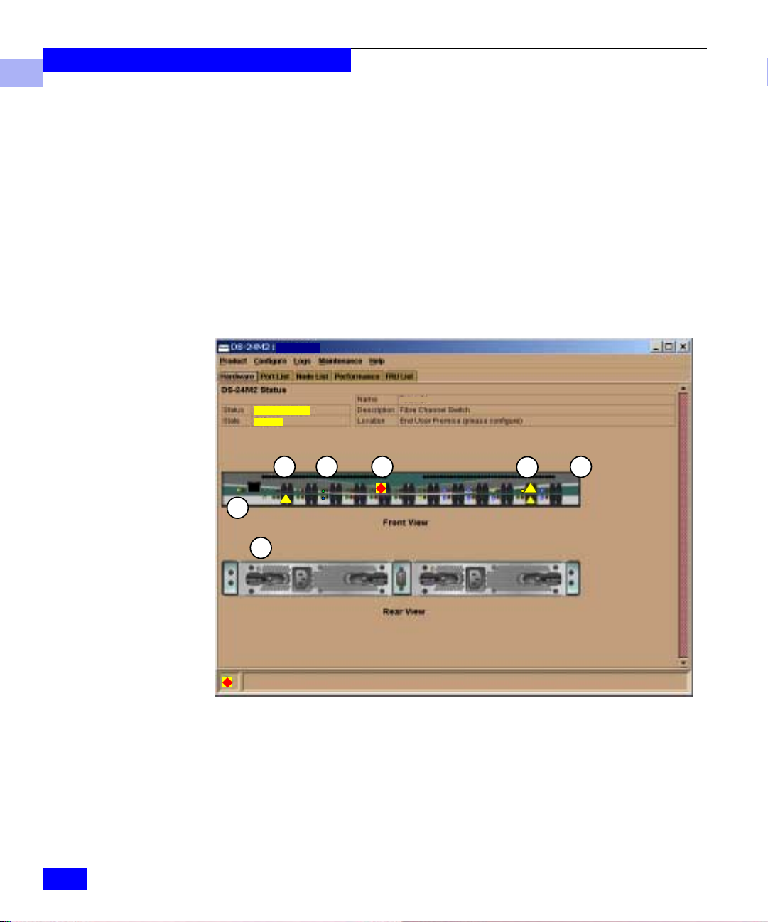
Monitoring and Managing the Switch
4
Operation Monitoring
Example
Determine hardware component operating status and states by the
simulated LED indicators and status symbols that appear on
hardware components. These simulated LEDs and alert symbols
reflect the state of the actual hardware as changes occur.
Corresponding or additional descriptions of hardware status and
states also display when you click on components to display
Properties windows.
Figure 4-1 illustrates the DS-24M2 Hardware view with examples of
symbols and LED indicators that can help you monitor hardware
operation. The numbers in circles are keyed to descriptions in Table
4-2 on page 4-7. For more details on the meanings of symbols and
indicators, refer to Table 4-3 on page 4-35.
ABC 123
NOT OPERATIONAL
OFFLINE
1
ABC 123
3
4
52
6
4-6
7
Figure 4-1 Monitoring Hardware Operation Using the Hardware View
Connectrix DS-24M2 User Guide
Page 85

Monitoring and Managing the Switch
Table 4-2 Legend for Figure 4-1
Port attention indicator — A yellow triangle alert symbol can indicate an y
1
of these:
◆ A link incident occurred.
◆ The port is not operational.
◆ The port is in a non-standard mode of operation.
For a link incident, the status table at the top of the Hardware view changes
to reflect the reason for the alert. You can also note the reason by displaying
the Port Properties window for the port.
Port LED indicator — A green or blue indicator and an amber indicator to
2
the left of each port connector simulates LED operation on the actual switch
port. When the green/blue indicator illuminates, the port is on line and
operating at 1 Gb/s (if gr een) o r 2 Gb/s (i f blue). When the amber in dicator
illuminates continuously (not blinking), the port has failed.
Port failure indicator — A red and yell ow diamond on a port connec tor
3
indicates that the port has failed.
Beaconing — When a amber LED indicator appears by a port and an
4
attention indicator appears below the port connector, beaconing is enabled
on the ports.
4
Using the Hardware View
4-7
Page 86

Monitoring and Managing the Switch
4
Table 4-2 Legend for Figure 4-1 (continued)
Not Installed — The port optics are not installed, or the feature that
5
provides additional port functionality is not enabled.
Power , System Err or, and Unit Beaconing indicators — The green/blue and
6
amber indicators on the far left of the front view simulates the power and
system error LEDs on the actual switch.
◆ Power indicator — The green/blue indicator simulates the power LED
on the switch. When the indicator illuminates, the switch is connected
to facility AC power and operational. The indicator will be on if either
power supply is operating.
◆ System Error indicator — The amber indicator simulates the system
error light on the switch. When this indicator illu minates, an event has
occurred requiring immediate attention, such as a system, fan , power
supply, or port failure. View details of system errors by selecting Event
Log from the Product Manager Logs menu. The indicator in the
Hardware View and the LED on the actual unit remains illuminated
until you clear the event by right-clicking on the switch gra p hic (away
from any har dwar e component) an d selectin g Clear System Error Light
from the pop-up menu.
4-8
If the amber indicator flashes, this indicates that unit beaconing has been
enabled for the switch. E nable or di sable unit beaconing b y right-clic king on the
switch graphic (away from any hardware components) and selecting Enable
Unit Beaconing from the pop-up menu.
Power Supply status — Each AC power connector indicates the location of
7
an internal power supply. A n a mber LED indicator is located in the upper
left corner of each AC power connector. The indicator illuminates if the
power supply has failed and requires service. The indicator is off if the
power supply is active.
If a red and yellow diamond appears on a power connector, the internal
power supply for that connector has failed. In this case, the green/blue
indicator at the top left of the connector does not illuminate. When the
green/blue indicator is on and no alert symbol appears, the power supply
is operational.
The switch operates with one power supply; however, you should replace a failed
power supply as soon as possible to retain redundancy.
Connectrix DS-24M2 User Guide
Page 87

Monitoring and Managing the Switch
4
Obtaining Hardware Information
Displaying FRU
Properties
Displaying Port
Properties
This section explains how to access the FRU Properties, Port
Properties, and Switch Properties windows.
You ca n d isplay a FRU Properties window for a power supply (AC
connector) in any of these ways:
◆ Double-click the FRU in the Hardware view.
◆ Select the FRU in the Hardware view; then select FRU and FRU
Properties from the Product menu.
◆ Double-click on a row in the FRU List view.
The FRU Properties window shows:
◆ FRU name
◆ Slot position relative to identical FRUs insta lled in the unit
◆ State: active or failed
◆ Part number
◆ Serial number
You ca n display a Port Properties window in any of these ways:
◆ In the Hardware view, do either of these:
• Double-click a port.
• Right-click a port and click Port Properties on the pop-up
menu.
◆ In the Port List view, do either of these:
• Double-click a row.
• Right-click a row and click Port Properties on the pop-up
menu.
◆ In the Node List view, right-click a port’s row and click Port
Properties on the pop-up menu.
◆ In the Performance view, right-click a port’s bar graph and click
Port Properties on the pop-up menu.
The Port Properties window shows the following for the selected
port. Refer to Configuring Ports on page 5-17 for more information on
some of these paramete rs.
◆ Port Number — The physical port number.
◆ Port Name — A user-defined name or description.
Using the Hardware View
4-9
Page 88

Monitoring and Managing the Switch
4
◆ Type:
• G_Port— A configurable port type that restricts a port to
operate either as an F_Port or E_Port.
• E_Port — A port that connects to another switch’s E_Port over
an ISL.
• F_Port — A port that connects to a fabric-enabled device.
• FL_Port — A port that connects to a private loop device.
• Fx_Port — A configurable port type that restricts a port to
operate either as an F_Port or FL_Port.
• Gx_Port — A configurable port type that restricts a port to
operate either as an F_Port, FL_Port, or E_Port.
◆ Operating Speed — The current data speed for the port:
1Gb/sec, 2 Gb/sec, or Not Established. Not Established appears
if Negotiate was set for the port through the Configure Ports
dialog box and the data speed has not been resolved between the
port and the attached device, or if the port and device are not
communicating.
◆ Port WWN — The port’s 16-digit World Wide Name (WWN).
4-10
◆ Block Configuration — Blocked or unblocked.
◆ LIN Alerts Configuration — Indicates whether LIN alerts are
enabled (the default setting) or disabled.
◆ FAN Configuration — Indicates whether Fabric Address
Notification (FAN) is on or off when the port is operating as an
FL_Port.
◆ Beaconing — The beaconing status for the port (enabled or
disabled) . T o enable or disable beaconing, right-click the port and
click the box to the left of Enable Beaconing to add or remove a
checkmark.
◆ Link Incident — Description of the last link incident that
occurred on the port.
◆ Operational State:
• Beaconing
• Inactive
• Invalid Attachment
• Link Incident
• Link Reset
• No Light
• Not Operational
Connectrix DS-24M2 User Guide
Page 89

Monitoring and Managing the Switch
• Online
• Offline
• Port Failure
• Segmented E_Port
• Testing
Table 4-3 on page 4-35 describes the operational states.
◆ Reason — Reason for invalid attachment, E_Port segmentation,
or inactive state .
E_Port segmentation can occur onl y when the switch is connected to
another switch or director. If the port is not segmented, this field displays
Segment not defined.
• Invalid attachment messages:
01 Unknown — Invalid attachment reason cannot be
–
determined.
–
02 ISL connection not allowed on this port — Port
is configured as an F_Port, but is connected to another
switch.
–
03 ELP rejected by the attached switch — This
switch transmitted an ELP (exchange link protocol) frame
that was rejected by the switch at the other end of the ISL.
–
04 Incompatible switch at the other end of the
ISL
— The Interop Mode for this switch is set to Open
Fabric and the switch at the other end of the ISL is
configured for McDATA Fabric. (Refer to Configuring
Operating Parameters on page 5-4.)
–
05 External loopback adapter connected to the
port
— A loopback plug is connected to the port.
–
06 N_Port connection not allowed on this port —
The port is configured as an E_Port, but attaches to a node
device.
–
07 Non-McDATA switch at other end of the ISL —
The cable is connected to a non-EMC switch and the
Interop Mode for this switch is set to McDATA Fabric.
–
08 ISL connection not allowed on this port — The
port is configured as an F_Port, but attaches to another
switch.
4
Using the Hardware View
4-11
Page 90

Monitoring and Managing the Switch
4
– 10 Port binding violation - unauthorized WWN —
The WWN entered to configure port binding is not valid or
a Nickname was used that is not configured through the
Product Manager or Fabric Manager for the attached
device.
–
11 Unresponsive node connected to port — Possible
causes are:
•Hardware problem on switch or on a connected node
where ELP frames are not delivered, the response is not
received, or a fabric login in (FLOGI) cannot be
received. There may be problems in the switch SBAR.
•Faulty or dirty cable connection.
•Faulty host bus adapters that do not send out an FL OGI
within a reasonable timeframe.
• Reasons for seg m e nt at i o n:
– Incompatible operating parameters; for example,
R_A_TOV or E_D_TOV might be inconsistent.
– Duplicate Doma in IDs.
– Incompatible zoning configurations.
– Build fabric p rotocol error.
– No switch in fabric is capabl e of being principal switch.
– No response from an attached switch.
• Reason for an inactive state: optics speed conflict. An inactive
state occurs if you set the port’s data speed to 2 Gb/sec for a
2 Gb/s port module, and then replace the port module with a
1 Gb/s module. To activate the port in this case, replace the
module with a module that supports 2 Gb/s.
◆ Threshold Alert — If a threshold alert exists for the port, an alert
indicator (yellow triangle) appears by the Threshold Alert field ,
and the configured name for the last alert received appears in the
field.
4-12
Connectrix DS-24M2 User Guide
Page 91

Monitoring and Managing the Switch
4
Displaying Switch
Properties
To di splay a Switch Properties window, double-click the front view
of the switch away from any ports (or right-click the switch away
from any ports and click Properties on the pop-up menu).
The Switch Properties window displays:
◆ Switch name, description, location, and contact, as configured
through the Configure Identification dialog box
◆ Fibre Channel WWN identifier for the switch
◆ Product type number
◆ Product model number
◆ Product manufacturer
◆ Product serial number
◆ Engineering change (EC) level
◆ Firmware level
◆ Management Style: Open Systems
◆ Preferred Domain ID (set through the Configure Operating
Parameters dialog box)
◆ Active Domain ID (the actual Domain ID assigned to the switch)
◆ Fibre Channel Address Domain
◆ CTP state (active or inactive)
◆ Switch Speed: 2 Gb/s
◆ Switch Binding — Enabled if the optional Enterprise Fabric
Extensions features are installed and enabled; otherwise,
disabled.
Using the Hardware View
4-13
Page 92

Monitoring and Managing the Switch
4
Using Menu Options
Switch Menu Right-click on any area of the switch illustration where a hardware
Right click on various parts of the Hardware view to displa y pop- up
menu options for displaying s tatus and information and for
controlling the switch and various hardware components.
component is not installed t o display the following menu options:
◆ Switch Properties — Displays switch parameters. Refer to
Displaying Switch Properties on page 4-13.
◆ Enable Unit Beaconing — Click the checkbox to toggle unit
beaconing on or off. When the checkbox is checked, unit
beaconing is on, and the system error light on the actual switch
blinks to help users locate the unit in an equi pment room. (The
amber indicator on the Hardware view also blinks when
beaconing is enabled. )
When you click the checkbox to remove the checkmark, unit
beaconing is off and the amber LED goes out.
You can enable beaconing only if the system error light is off, meaning
there are no system errors.
◆ Clear System Error Light — Turns off the amber system error
light, located below the green/blue power LED on the switch.
(This also turns off the amber system error light indicator in the
Hardware view.)
◆ IPL Switch — Initiates an IPL on the switch.
4-14
!
◆ Set Switch Date and Time — Sets the date/time. You can also
◆ Set Switch Online State —Displays the current state (off line or
Connectrix DS-24M2 User Guide
Refer to Executing an IPL on page 7-4.
CAUTION
An IPL is not intended for ordinar y or casual use and shoul d be
performed only when directed by your support personnel.
configure the switch to synchronize its date and time to the
Connectrix service processor. Refer to Configuring the Date and
Time on page 5-31 for the procedure.
on line) and provides a button for changing the state. Refer to
Setting the Online State on page 7-6 for more information.
Page 93

Monitoring and Managing the Switch
4
!
CAUTION
Before setting the switch off line, warn administrators and
users currently operating attached devices that the switch is
going off line and that there will be a disruption of port
operation. Also, request that the devices af fecte d by an
interruption of data flow be set off line.
Port Menu While in the Hardware view, right-click on any port to display the
following menu optio ns:
◆ Port Properties — Displays a Port Properties window, described
under Displaying Port Proper ties on page 4-9.
◆ Port Technology — Displays a Port Technology window, which
contains displays the followin g information:
• Port number
• Connector type: Always LC Connector
• Transceiver: Lo ngwave Laser or Shortwave Laser.
• Distance: General distance range for port transmission. This
can be either short to long distances for the longwave laser LC
transceiver or short distances for the shortwave laser LC
transceivers.
• Media: The Fibre Channel mode and optic size. For the
longwave laser LC transceiver, this would be singlemode 9
micron. For the shortwave laser LC transceiver, this would be
multimode 50-micron or 62.5-micron.
• Speed: 2 GBit/1 GBit.
◆ Block Port — Click to display a checkmark and block port
transmission If the port is blocked, a node attached to the port is
prevented from logging into the switch or communicating with
other devices attached to switch ports. A blocked port
continuously transmits offline sequences (OLS). Click to remove
the checkmark and unblock the port. If unblocked, a node
attached to the port can communicate with the switch and
communicate with other nodes attached to the switch.
◆ Enable Beaconing — Click this to make the amber LED by the
port blink on the actual switch and the amber indi cator blink for
the port in the Hardware view. This enables users to locate the
Using the Hardware View
4-15
Page 94
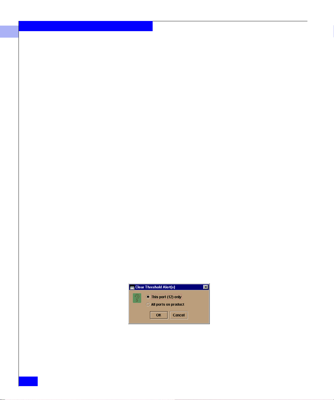
Monitoring and Managing the Switch
4
unit where the port is located. When a blinking amber LED
indicator appears by a port, an attention indicator appears below
the port's connector in the Hardware view.
◆ Port Diagnostics — This option is used by service personnel to
run internal and external loopback tests on the port.
◆ Clear Link Incident Alert(s) — Click this to clear the attention
indicators on the Hardware view, the Port Lis t view, and the
Performance view. In addition, the procedure clears the alert
description in the Port Properties window. If there are no link
incident alerts set for a port, no actions occur. Although you can
manually clear link incidents, they may also be cleared by actions
outside of the user interface, such as when rebooting the
Connectrix service processor.
◆ Reset Port — Click to display a confirmation window; then click
Yes to reset the port. If a switch is attached to the port and is on
line, this operation sends a link reset to the attached switch,
otherwise this action disables port beaconing for the port, and if
the port is in a failed state, such as after failing a loopback test, the
reset restores the port to an operational state, clearing the service
required (amber) LED. The reset does not affect other ports in the
switch.
4-16
◆ Port Binding — Allows you to enable or disable port binding. For
details, refer to Configuring Ports on page 5-17.
◆ Clear Threshold Al ert(s) — Allows you to clear threshold alerts.
Select the appropriate option to clear alerts for the selected port
only or all ports on the switch. This clears all attention indicators
that notify users of threshold alerts in dialog boxes and views.
This action also restarts the notification interval and the
cumulative minutes for utilization % interval.
Figure 4-2 Clear Threshold Alert(s) Window
For more information on threshold alerts, refer to Configuring
Threshold Alerts on page 5-33.
Connectrix DS-24M2 User Guide
Page 95
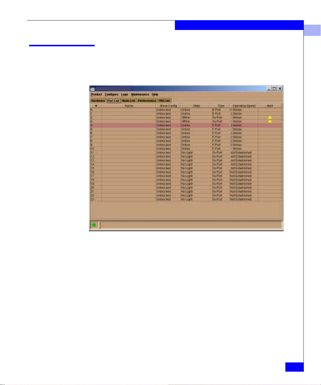
Using the Port List View
To display the Port List view (Figure 4-3), select the Product Manager
Port List tab.
DS-24M2: S34-A
Monitoring and Managing the Switch
2
2
2
2
2
2
2
2
2
2
2
2
2
2
2
2
4
Figure 4-3 Port List View
The Port List view displays the following inform ation on all ports
that can be installed in the switch. All in fo rmation is updated
automatically.
◆ # — Port number: 0 through 23.
◆ Name — Port name as configured through the Configure Ports
dialog box.
◆ Block Confi g — Blocked/unblocked configuration of the port as
set through one of these:
• The Configure Ports dialog box.
• The Block Port option available through:
– Port right-click menus in the hardware view
– Port row right-click menus in the Port List vi ew
Using the Port List View
4-17
Page 96

Monitoring and Managing the Switch
4
– Port bar graph right-click menus in the Performance view
Possible states are:
• Blocked — Devices communicating with the po rt are
prevented from logging into the switch or communicating
with other devices attached to switch ports. A blocked port
continuously transmits OLS.
• Unblocked — Devices communicating with the port can log
in to the switch and communicate with devices attached to
any other unblocked port in the same zone.
◆ State — Can be any of the following:
• No Light
• Online
• Offline
• Beaconing
• Link Reset
• Not Operational
• Not Installed
• Invalid Attachment
• Port Failure
• Segmented E_Port
• Link Incident
• Testing
• Inactive
For more information on these states and corresponding alert
symbol and LED indicator operations in the Har dware vi ew, refer
to Port Operational States on pag e 4-35.
4-18
◆ Type:
• E Port if another E_Port is attached
• F Port if an N_Port is attached
• FL Port if an NL_Port is attached
• G Port if the port is capable of acting as either an F_Port or an
E_Port, but nothing is currently attached
• Fx Port if the port is an unconfigured Fx_Port, which is a
configurable port type that restricts a port to operate either as
an F_Port or FL_Port.
• Gx Port if the port is an unconfigured Gx_Port, which is a
configurable port type that restricts a port to operate either as
an F_Port, FL_Port, or E_Port.
Connectrix DS-24M2 User Guide
Page 97

Monitoring and Managing the Switch
◆ Operating Speed — The current data speed for the port:
1Gb/sec, 2 Gb/sec, or Not Established. Not Established appears
if Negotiate was set for the port through the Configure Ports
dialog box and the data speed has not been resolved between the
port and the attached device, or if the port and device are not
communicating.
◆ Alert — Displays a yellow triangle if a link incident occurs on the
port or if the port's LED is beaconing. red and yellow di amonds
appear for port failures or for ports requiring service.
Double-click the row to display the reason for the alert in the Port
Properties window.
4
Displaying Port Properties
Menu Options
To di splay a Port Properties window for a port, double-click the
port’s row (or right-click the row and click Port Properties on the
pop-up menu). Refer to Displaying Port Properties on page 4-9 for
descriptions of the port properties.
Right-click a row to display a po p-up menu with the following
port-related options. Refer to the pages shown for more information
◆ Port Properties — Refer to Displaying Port Properties on page 4-9.
◆ Port Technology — Refer to Port Menu on page 4-15.
◆ Block Port — Refer to Port Menu on page 4-15.
◆ Enable Beaconing — Refer to Port Menu on page 4-15.
◆ Port(s) Diagnostics — Is used by service personnel to run an
internal loopback and external loopback test on the port.
◆ Clear Link Incident Alert — Refer to Port Menu on page 4-15.
◆ Reset Port — Refer to Port Menu on page 4-15.
◆ Port Binding — Allows you to enable or disable port binding. For
details, refer to Configuring Ports on page 5-17.
◆ Clear Threshold Al ert(s) — Allows you to clear threshold alerts.
Select the appropriate option to clear alerts for the selected port
only or all ports on the director. This clears all attention indicators
that notify users of threshold alerts in dialog boxes and views.
This action also restarts the notification interval and the
cumulative minutes for utilization % interval.
Using the Port List View
4-19
Page 98

Monitoring and Managing the Switch
4
Figure 4-4 Clear Threshold Alert(s) Window
For more information on threshold alerts, refer to Configuring
Threshold Alerts on page 5-33.
4-20
Connectrix DS-24M2 User Guide
Page 99

Using the Node List View
To di spla y the Node List view (Figure 4-5), select the Product
Manager Node List tab.
This view displays informatio n about all node attachments to any
F_Ports on the switch, sorted by port number. All data is updated
automatically as devices log in and log out.
DS24M2: S34-A
Monitoring and Managing the Switch
4
Figure 4-5 Node List View
Information that appears for each node includes:
◆ Port # — Port number: 0 throu g h 23.
◆ Address — Displays the Fibre Channel address of the node.
◆ Node Type — N_Port or NL_Port.
◆ Port WWN — Port World Wide Name of the attached node
(N_Port). The WWN is prefixed by the manufacturer’s name of
the host bus adapter that attaches to the device.
Using the Node List View
4-21
Page 100

Monitoring and Managing the Switch
4
If a nickname is assigned to the WWN and Display Options is set
to Nickname, the nickname appears instead of the WWN. (Refer
to Defining Nicknames on page 4-24.)
To change a node’s display between the WWN and nickname:
a. Right-click the port’s row.
b. On the pop-up menu, move the cursor over Display Options.
c. Click the desired option on the pop-up sub-menu.
◆ Unit Type — Attached device, (if the device provides this
information):
Unknown
Other
Hub
Switch
Gateway
Converter
HBA
Proxy-agent
Storage device
Host
Storage subsystem
Module
Software driver
4-22
The unit type comes directly from the device sense ID when the device
attaches to the port d u ring login. If the con ne c tion is lost to the devi ce,
the type appears as unspecified, since the device is no longer logged in
to the port. When the device logs back in, the unit type is updated.
◆ BB_Credit — The buffer-to-buffer credit that the attached node
has available.
Connectrix DS-24M2 User Guide
 Loading...