

Page 1

EMC® Connectrix® B Series
ED-48000B
Version 5.2
Hardware Reference Manual
P/N 300-002-855
REV A02
EMC Corporation
Corporate Headquarters:
Hopkinton, MA 01748
1
-508-435-1000
www.EMC.com
-9103
Page 2

Copyright © 2001-2006 EMC Corporation. All rights reserved.
Published December, 2006
EMC believes the information in this publication is accurate as of its publication date. The information is
subject to change without notice.
THE INFORMATION IN THIS PUBLICATION IS PROVIDED "AS IS." EMC CORPORATION MAKES NO
REPRESENTATIONS OR WARRANTIES OF ANY KIND WITH RESPECT TO THE INFORMATION IN THIS
PUBLICATION, AND SPECIFICALLY DISCLAIMS IMPLIED WARRANTIES OF MERCHANTABILITY OR
FITNESS FOR A PARTICULAR PURPOSE.
Use, copying, and distribution of any EMC software described in this publication requires an applicable
software license.
For the most up-to-date listing of EMC product names, see EMC Corporation Trademarks on EMC.com.
All other trademarks used herein are the property of their respective owners.
Regulatory Agency Information
EMC Connectrix B systems have been extensively tested and certified to meet UL60950, CSA 22.2 No 60950,
IEC 60950/EN60950; Safety of Information Technology Equipment including Electrical Business
Equipment, FCC Rules Part 15 Subpart B; CISPR22 Class A; European EMC Directive 89/336/EEC on,
electromagnetic compatibility.
The EMC Connectrix B system is a Stationary Pluggable Type B system.
This class A digital apparatus complies with Canadian ICES-003.
Cet appareil numérique de la classe A est conforme à la norme NMB-003 du Canada.
Warning!
This is a Class A product. In a domestic environment this product may cause radio interference in which
case the user may be required to take adequate measures.
Achtung!
Dieses ist ein Gerät der Funkstörgrenzwertklasse A. In Wohnbereichen können bei Betrieb dieses Gerätes
Rundfunkstörungen auftreten, in welchen Fällen der Benutzer für entsprechende Gegenmaßnahmen
verantwortlich ist.
Attention!
Ceci est un produit de Classe A. Dans un environnement domestique, ce produit risque de créer des
interférences radioélectriques, il appartiendra alors à l'utilisateur de prendre les mesures spécifiques
appropriées.
2
EMC Connectrix B Series ED-48000B Hardware Reference Manual
Page 3

This equipment generates, uses, and may emit radio frequency energy. The equipment has been type tested
and found to comply with the limits for a Class A digital device pursuant to Part 15 of FCC rules, which are
designed to provide reasonable protection against such radio frequency interference.
Operation of this equipment in a residential area may cause interference in which case the user at his own
expense will be required to take whatever measures may be required to correct the interference.
Any modifications to this device - unless expressly approved by the manufacturer - can void the user’s
authority to operate this equipment under part 15 of the FCC rules.
The following is a template block of text to meet South Korean RRL Agency Requirements. This block is
needed for hardware manuals (both customer and service) only. If you need to include such a block in your
manual, please submit a request to Illustration and provide a sample for setting up copy.
EMC Connectrix B Series ED-48000B Hardware Reference Manual
3
Page 4

4
EMC Connectrix B Series ED-48000B Hardware Reference Manual
Page 5

Contents
Preface.............................................................................................................................. 9
Chapter 1 Overview
ED-48000B features........................................................................... 16
Hardware components..................................................................... 17
Portside of the ED-48000B........................................................ 19
Nonport Side of the ED-48000B............................................... 20
High availability ............................................................................... 21
Reliability ........................................................................................... 22
Serviceability ..................................................................................... 23
PB-48K-18i blade............................................................................... 24
Software features............................................................................... 26
Port numbering ................................................................................. 27
Chapter 2 Installation, Setup, and Login
Overview............................................................................................ 30
Time and items required.................................................................. 31
Site planning and safety guidelines ............................................... 32
Items included with the ED-48000B............................................... 34
Providing power to the ED-48000B................................................ 35
Establishing a serial connection...................................................... 37
Managing cables................................................................................ 39
Chapter 3 Initial Configuration Parameters
Overview............................................................................................ 44
Configure IP addresses for the ED-48000B ................................... 45
Establish an Ethernet connection.................................................... 48
EMC Connectrix B Series ED-48000B Hardware Reference Manual
5
Page 6

Contents
Customize a switch name................................................................ 49
Set the Domain ID............................................................................. 50
Verify the PID mode and connect to the fabric............................. 51
Enable software licenses.................................................................. 53
Back up the configuration ............................................................... 54
Chapter 4 Monitor System Components
Overview............................................................................................ 56
Port blades ......................................................................................... 57
CP blades ........................................................................................... 61
Power supplies.................................................................................. 63
Blower assemblies............................................................................. 65
WWN card......................................................................................... 67
Cable management tray................................................................... 70
Chapter 5 Remove and Replace System Components
Overview............................................................................................ 72
Replacing the cable management tray........................................... 73
Replacing a port blade and filler panel ......................................... 77
Removing a port blade ............................................................. 81
Replacing a CP blade........................................................................ 85
Replacing a power supply and filler panel................................... 96
Replacing a blower assembly........................................................ 100
Replacing the WWN bezel and card............................................ 104
Installing and removing SFPs in a port blade ............................ 112
Chapter 6 Chassis Replacement
Overview.......................................................................................... 114
Time required .................................................................................. 114
Items required................................................................................. 115
Verify need for replacement.......................................................... 116
Record critical switch and SAN information.............................. 117
Disconnect from network and fabric ........................................... 122
Remove components from chassis............................................... 123
Remove and replace chassis.......................................................... 125
Install components into new chassis............................................ 127
Install modems (optional) ............................................................. 129
Verify correct operation of hardware........................................... 130
Configure new chassis serial number.......................................... 130
Verify correct operation of system................................................ 131
Reconnect system to network and fabric .................................... 133
6
EMC Connectrix B Series ED-48000B Hardware Reference Manual
Page 7

Verify correct configuration of fabric ........................................... 135
Cable routing tables........................................................................ 137
Chapter 7 Blade Support Notes
Overview.......................................................................................... 140
ED-48000B blade support............................................................... 141
CP blades................................................................................... 141
Port blade compatibility.......................................................... 142
Port blade configurations........................................................ 142
Planning the installation ................................................................ 143
Supported blade installation overview................................. 143
Chassis configuration setting ................................................. 143
Power requirements ................................................................ 144
Preparing to add new blades......................................................... 145
Upgrading to the latest Fabric OS version ........................... 145
Backing up the Director configuration and obtaining a SAN
profile......................................................................................... 146
Verifying a safe work space.................................................... 147
Labeling all the cables ............................................................. 147
Installing port blade procedures................................................... 148
Adding FC2-16 blades to an ED-48000B............................... 148
Validating the installation.............................................................. 150
Troubleshooting the installation............................................ 150
ED-48000B configuration form............................................... 151
Contents
Chapter 8 Setting Up and Installing Modems
Overview.......................................................................................... 158
Using high-availability connectivity ............................................ 159
Connecting modems....................................................................... 161
Setting up a remote modem system............................................. 162
Verifying the modem connection.................................................. 164
Appendix A Specifications
System architecture ........................................................................ 168
System size and weight ................................................................. 170
System blade and FRU weights ................................................... 171
Facility requirements ..................................................................... 172
Power specifications ...................................................................... 173
Power cords ..................................................................................... 174
Environmental requirements ........................................................ 178
Thermal policy.......................................................................... 179
EMC Connectrix B Series ED-48000B Hardware Reference Manual
7
Page 8

Contents
General specifications ................................................................... 180
Data transmission ranges ............................................................. 181
Fibre Channel port specifications ................................................ 182
CP blade specifications ................................................................. 183
Memory specifications............................................................ 183
Battery specifications .............................................................. 183
Serial port specifications......................................................... 184
Modem serial port specifications .......................................... 185
Regulatory compliance specifications ........................................ 186
FCC warning (USA only) ....................................................... 186
MICstatement (Republic of Korea) ....................................... 186
VCCI statement........................................................................ 187
BSMI statement (Chinese)...................................................... 188
CE statement ............................................................................ 189
Canadian requirements .......................................................... 189
Laser compliance..................................................................... 189
RTC battery .............................................................................. 190
Electrical safety ........................................................................ 190
Regulatory certifications......................................................... 190
Appendix B Troubleshooting
Overview ......................................................................................... 194
Obtaining chassis and component status ................................... 195
Interpreting POST and boot results ............................................ 196
POST.......................................................................................... 196
Boot............................................................................................ 197
Diagnostics ...................................................................................... 198
Troubleshooting the ED-48000B .................................................. 199
Appendix C Port Numbering Template
Template .......................................................................................... 204
Index.............................................................................................................................. 209
8
EMC Connectrix B Series ED-48000B Hardware Reference Manual
Page 9

Preface
As part of an effort to improve and enhance the performance and capabilities
of its product line, EMC from time to time releases revisions of its hardware
and software. Therefore, some functions described in this manual may not be
supported by all revisions of the software or hardware currently in use. For
the most up-to-date information on product features, refer to your product
release notes.
If a product does not function properly or does not function as described in
this manual, please contact your EMC representative.
Audience This manual is part of the EMC Connectrix Departmental Switch and
Enterprise Director documentation set, and is intended for use by
system administrators and technicians during installation and
configuration of the switches to help you operate, maintain, and
troubleshoot the ED-48000B. This document is specific to the
ED-48000B and Fabric OS version 5.2.
Related
documentation
Related documents include:
◆ EMC Connectrix B Series Diagnostic and System Error Message
Reference Manual
◆ EMC Connectrix B Series Fabric Watch Reference Manual
◆ EMC Connectrix B Series Management Information Base (MIB)
Reference Manual
◆ EMC Connectrix B Series Fabric OS Command Reference Manual
◆ EMC Connectrix B Series Web Tools Administrator’s Guide
◆ EMC Connectrix B Series Fabric OS Administrator’s Guide
◆ EMC Connectrix B Series ED-24000B Hardware Reference Manual
EMC Connectrix B Series ED-48000B Hardware Reference Manual
9
Page 10

Preface
◆ EMC Connectrix DS-8B3 and DS-16B3 Hardware Reference Manual
◆ EMC Connectrix Enterprise Director ED-12000B Hardware Reference
◆ EMC Connectrix Departmental Switch DS-32B2 Hardware Reference
◆ EMC Connectrix B Series DS-4100B Hardware Reference Manual
◆ EMC Connectrix B Series DS-4900B Hardware Reference Manual
◆ EMC Connectrix B Series DS-220B Hardware Reference Manual
◆ Brocade Fabric Manager Administrator’s Guide
Special term usage The following abbreviated terms are used throughout this document
for clarity and consistency.
Term Abbreviation Definition
Manual
Manual
ED-12000B control
processor blade
ED-24000B control
processor blade
ED-48000B control
processor blade
16-port 2-Gbit/sec port
blade
16-port 2-Gbit/sec port
blade
16-port 4-Gbit/sec port
blade
32-port 4-Gbit/sec port
blade
CP1 This CP manages the FC-16 port blades in an ED-12000B. It does not have
switching capabilities. All port blades can operate at either 1- and 2-Gbit/sec. It
only supports a dual domain configuration within the chassis.
CP2 This CP manages the FC2-16 port blades in a ED-24000B. This CP supports 1-
and 2- Gbit/sec port speeds. It provides switching capability at 2-Gbit/sec when
the FC2-16 is used. It supports both the dual domain and a single domain
configuration within the chassis.
CP4 This CP manages the FC2-16, FC4-16, and FC4-32 port blades in a ED-48000B.
This CP provides the Fibre Channel switching capability up to 4-Gbit/sec when the
FC4-16 or FC4-32 blades are used. It provides switching capability at 2-Gbit/sec
when the FC2-16 is used. It only supports a single domain configuration within the
chassis.
FC-16 A 16-port director port blade supporting 1- and 2- Gbit/sec port speeds. This port
blade is only compatible with the ED-12000B CP blades.
FC2-16 A 16-port director port blade supporting 1- and 2- Gbit/sec port speeds. This port
blade is only compatible with the ED-24000B or ED-48000B CP blades. Uses
newer technology to achieve higher performance with less power consumption
than FC-16.
FC4-16 A 16-port director port blade supporting 1-, 2-, and 4- Gbit/sec port speeds. This
port blade is only compatible with the ED-48000B CP blades. FC4-16 blades do
not support private devices.
FC4-32 A 32-port director port blade supporting 1-, 2-, and 4- Gbit/sec port speeds.This
port blade is only compatible with the ED-48000B CP blades. Uses the same
technology as in FC4-16 with built in daughter card to achieve higher port density
than FC4-16. FC4-32 blades do not support private devices.
10
EMC Connectrix B Series ED-48000B Hardware Reference Manual
Page 11

!
Term Abbreviation Definition
Preface
48-Port 4-Gbit/sec port
blade
16-port 4-Gbit/sec port
blade with 2-port, 1 GbE
(FCIP) capabilities
D1 Chassis NA The first generation director chassis. These chassis are unable to read the
D2 Chassis NA The second generation director chassis. In Fabric OS 5.0, use the chassisShow
D3 Chassis NA The third generation director chassis. In Fabric OS 5.0, use the chassisShow
PB-48K-48 A 48 port director port blade supporting 1, 2, and 4 Gbit/sec port speeds in
chassis mode 5 with port and exchange-based routing. This port blade is only
compatible with the ED-48000B CP blades.
PB-48K-18i A16-port Fibre Channel routing and FCIP blade that also has 2 GbE ports and is
compatible only with the ED-48000B (using chassis configuration option 5).
backplane revision number.
command to view the backplane revision number for this chassis, D2.
command to view the backplane revision number for this chassis, D3.
For definitions of SAN-specific terms, visit the Storage Networking
Industry Association online dictionary at
http://www.snia.org/education/dictionary.
Conventions used in
this guide
EMC uses the following conventions for notes, cautions, warnings,
and danger notices.
Note: A note presents information that is important, but not hazard-related.
CAUTION
A caution contains information essential to avoid data loss or
damage to the system or equipment. The caution may apply to
hardware or software.
WARNING
A warning contains information essential to avoid a hazard that can
cause severe personal injury, death, or substantial property damage
if you ignore the warning.
DANGER
A danger notice contains information essential to avoid a hazard
that will cause severe personal injury, death, or substantial property
damage if you ignore the message.
EMC Connectrix B Series ED-48000B Hardware Reference Manual
11
Page 12

Preface
Typographical conventions
EMC uses the following type style conventions in this document:
Normal Used in running (nonprocedural) text for:
• Names of interface elements (such as names of windows,
dialog boxes, buttons, fields, and menus)
• Names of resources, attributes, pools, Boolean expressions,
buttons, DQL statements, keywords, clauses, environment
variables, filenames, functions, utilities
• URLs, pathnames, filenames, directory names, computer
names, links, groups, service keys, file systems, notifications
Bold: Used in running (nonprocedural) text for:
• Names of commands, daemons, options, programs,
processes, services, applications, utilities, kernels,
notifications, system call, man pages
Used in procedures for:
• Names of interface elements (such as names of windows,
dialog boxes, buttons, fields, and menus)
• What user specifically selects, clicks, presses, or types
Italic: Used in all text (including procedures) for:
• Full titles of publications referenced in text
• Emphasis (for example a new term)
• Variables
Courier: Used for:
• System output, such as an error message or script
• URLs, complete paths, filenames, prompts, and syntax when
shown outside of running text
Courier bold: Used for:
• Specific user input (such as commands)
Courier italic: Used in procedures for:
• Variables on command line
• User input variables
< >
[ ]
|
{ }
...
Angle brackets enclose parameter or variable values supplied by
the user
Square brackets enclose optional values
Vertical bar indicates alternate selections - the bar means “or”
Braces indicate content that you must specify (that is, x or y or z)
Ellipses indicate nonessential information omitted from the
example
12
EMC Connectrix B Series ED-48000B Hardware Reference Manual
Page 13

Where to get help EMC support, product, and licensing information can be obtained as
follows.
Product information — For documentation, release notes, software
updates, or for information about EMC products, licensing, and
service, go to the EMC Powerlink website (registration required) at:
http://Powerlink.EMC.com
Technical support — For technical support, go to EMC Customer
Service on Powerlink. To open a service request through Powerlink,
you must have a valid support agreement. Please contact your EMC
sales representative for details about obtaining a valid support
agreement or to answer any questions about your account.
Your comm ents Your suggestions will help us continue to improve the accuracy,
organization, and overall quality of the user publications. Please send
your opinion of this document to:
techpub_comments@EMC.com
Preface
EMC Connectrix B Series ED-48000B Hardware Reference Manual
13
Page 14

Preface
14
EMC Connectrix B Series ED-48000B Hardware Reference Manual
Page 15

1
Invisible Body Tag
Overview
The ED-48000B represents the next generation of advanced Fibre
Channel directors used to intelligently interconnect storage devices,
hosts, and servers in a Storage Area Network (SAN). The ED-48000B
director is the highest-performance and highest-scalability director
offered by EMC. It satisfies the most demanding Reliability,
Availability, and Serviceability (RAS), performance, and scalability
requirements of a director, while delivering investment protection,
interoperability, and fabric-based intelligence advantages.
This chapter includes the following sections:
◆ ED-48000B features............................................................................ 16
◆ Hardware components...................................................................... 17
◆ High availability................................................................................. 21
◆ Reliability ............................................................................................ 22
◆ Serviceability....................................................................................... 23
◆ PB-48K-18i blade ................................................................................ 24
◆ Software features................................................................................ 26
◆ Port numbering .................................................................................. 27
Overview
15
Page 16

Overview
ED-48000B features
Key features of the ED-48000B include the following:
◆ Up to 384 ports in a single chassis, providing high port density for
a scalable solution to drive high-port-count SAN configurations.
◆ A single logical switch, that encompasses all port blades in the
chassis for ease of maintenance. The IP address for this single
logical switch is shown as SWITCH under the ipaddrShow
command. This director does not support the dual domain
configuration.
◆ Support for high-performance port blades running at 1-, 2-, or
4-Gbit/sec, enabling flexible system configuration:
• 16-port, 4-Gbit/sec blades (FC4-16)
• 32-port, 4-Gbit/sec blades (FC4-32)
• 48-port, 4-Gbit/sec blades (PB-48K-48)
• PB-48K-18i blade: Fibre Channel Routing Services and FCIP
using the PB-48K-18i blade. See the PB-480000-18i Hardware
Reference Manual for more information.
◆ Dual-redundant control processors provide high availability and
enable nondisruptive software upgrades.
16
◆ Redundant and hot swappable CPs, power supplies, and blower
assembly enable a high availability platform for mission critical
SAN applications.
◆ Supports 1-, 2-, and 4-Gbit/sec auto-sensing Fibre Channel ports.
Trunking technology groups up to eight ports to create high
performance 32-Gbit/sec ISL trunks between switches.
◆ Universal ports self-configure as E_Ports, F_Ports, or FL_Ports.
EMC Connectrix B Series ED-48000B Hardware Reference Manual
Page 17

Hardware components
The ED-48000B features a modular and scalable mechanical
construction that allows a wide range of flexibility in installation,
fabric design, and maintenance. The ED-48000B consists of the
following:
◆ Up to eight hot-swappable port blade assemblies, which can be
configured in a single chassis, delivering up to 384 Fibre Channel
ports
◆ Two slots for control processor (CP) blade assemblies (slots 5 and
6):
• A single active CP blade can control all 384 ports in the
• The standby CP blade assumes control of the switch if the
◆ Modular hot-swappable field replaceable units (FRUs):
• 16-port, 4-Gbit/sec blades (FC4-16)
• 32-port, 4-Gbit/sec blades (FC4-32)
• 48-port, 4-Gbit/sec blades (PB-48K-48)
• 18-port, 16 FC + 2 GbE (PB-48K-18i, up to 2 blades per chassis,
• Two CP blades (CP4)
• Small form-factor pluggable (SFP) optical transceivers
• 3 blower assemblies
• Up to 4 power supplies (four power supplies are required
◆ Cables, blades, and power supplies are serviced from the port
side of the ED-48000B, and blowers are serviced from the nonport
side
Overview
chassis.
active CP fails.
supporting Fibre Channel Routing Services and FCIP)
when using the PB-48K-18i blade in the chassis)
◆ Improved cable management using a redesigned cable
management tray and chassis door
◆ Three blowers, providing cooling, allowing continuous operation
even if one blower fails
◆ Constant intake and FRU temperature monitoring
Hardware components
17
Page 18

Overview
◆ World Wide Name (WWN) card on the nonport side, to maintain
chassis-specific information such as WWNs, IP addresses, and
summary status information of each port blade assembly and
power supply through LEDs
◆ Redundant AC primary power connections to allow two primary
power connections for higher availability
◆ Supports up to eight of the following port blades:
• 16-port 2-Gbit/sec port blade (FC2-16)
• 16-port 4-Gbit/sec port blade (FC4-16)
• 32-port 4-Gbit/sec port blade (FC4-32)
• 48-port 4-Gbit/sec port blade (PB-48K-48)
• 18-port, 16 FC + 2 GbE (PB-48K-18i, up to two blades per
chassis)
◆ Small Form-Factor Pluggable (SFP) optical transceivers utilized
for 1-, 2-, and 4-Gbit/sec ports
18
EMC Connectrix B Series ED-48000B Hardware Reference Manual
Page 19
Portside of the ED-48000B
Overview
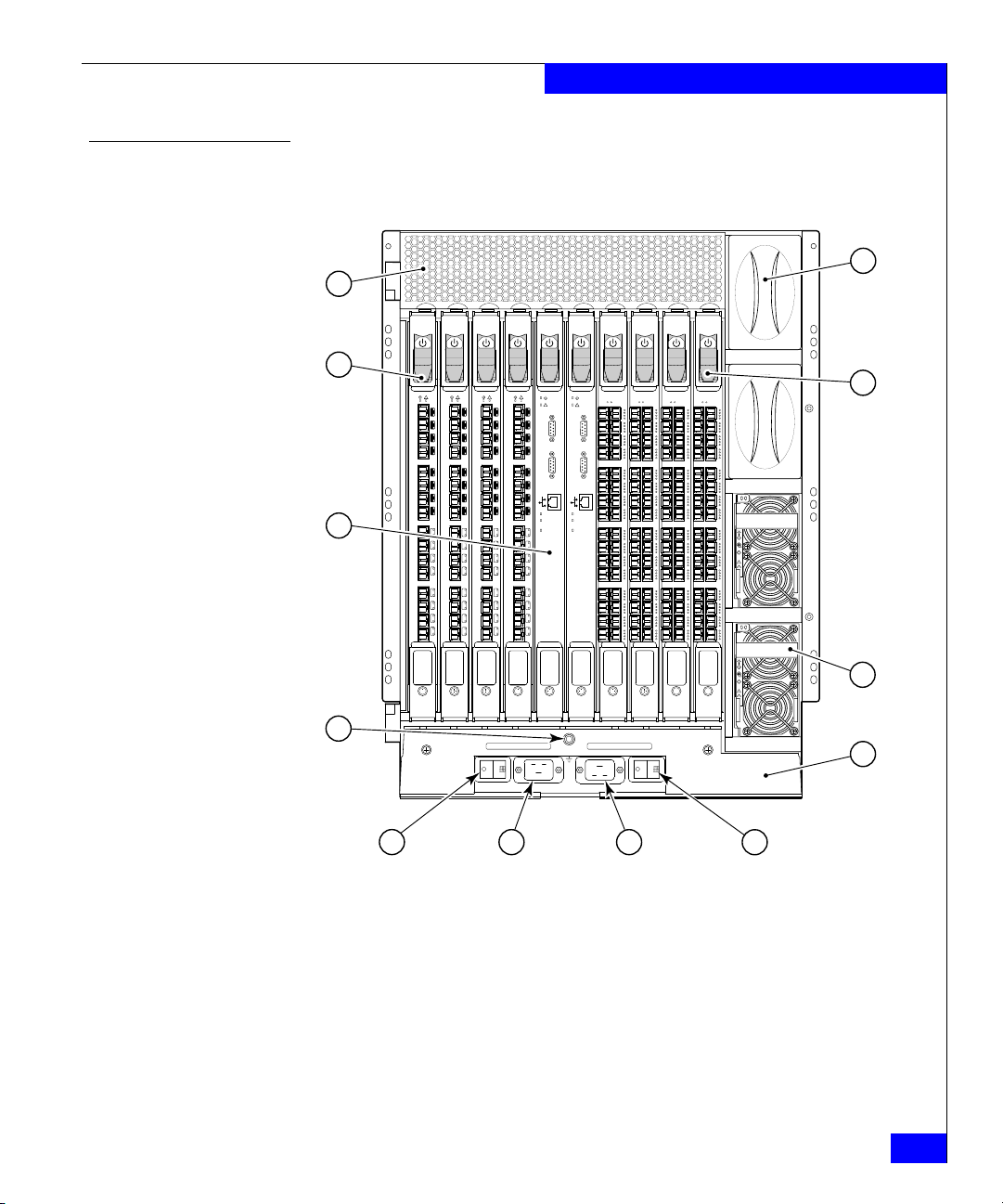
Figure 1 displays the portside of the ED-48000B director.
12
1
1 2 3 4 5 6 7 8 9 10
2
3
4
56-0000590-01RevA
56-0000590-01RevA
56-0000590-01RevA
!
!
15
15
14
14
13
13
12
12
11
11
10
10
9
9
8
8
7
7
6
6
5
5
4
4
3
3
2
2
1
1
0
0
FC4
FC4
16
16
5
56-0000590-01RevA
!
!
!
15
14
13
12
IOIOIRS- 232
11
10
9
8
Link
10/100Mb/s
ActiveCP
7
6
5
4
3
2
1
0
CP4
!
IOIOIRS- 232
Link
10/100Mb/s
ActiveCP
CP4
200-240 VAC12A 50-60 Hz
15
14
13
12
11
10
9
8
7
6
5
4
3
2
1
0
FC4
FC4
16
16
POWER SUPPLY 1&3 POWER SUPPLY 2&4
200-240 VAC12A 50-60 Hz
6 7
Figure 1 Port side of the ED-48000B director
FC4
POWER SUPPLY 4
11
POWER SUPPLY 3
!
!
POWER SUPPLY 2
FC4
FC4
32
32
FC4
32
32
!
!
POWER SUPPLY 1
10
9
8
1 Exhaust Vent 7 AC Power Connector (for Power Supplies 2 & 4)
2 FC4-16 Port Blade 8 AC Power Switch (for Power Supplies 2 & 4)
3 CP4 Blade (Control Processor Blade 9 Cable Management Tray
4 Grounding Strap Connector 10 Power Supply #1
5 AC Power Switch (for Power Supplies 1 & 3) 11 FC4-32 Port Blade
6 AC Power Connector (for Power Supplies 1 & 3) 12 Power Supply Filler Panel
Hardware components
19
Page 20
Overview
Nonport Side of the ED-48000B
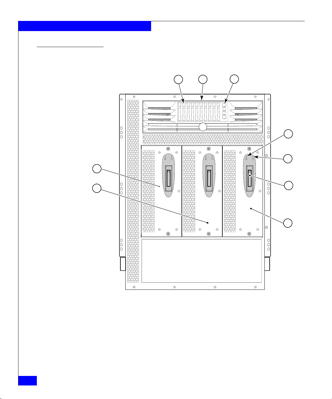
Figure 2 displays the nonport side view of the ED-48000B.
10 pwr4
3
pwr3
pwr2
pwr1
1
2
987654321
4
5
9
8
6
7
Figure 2 Nonport side of the ED-48000B director
1 Port Blade and CP Blade LEDs 6 Blower Handle
2 WWN Bezel 7 Blower Assembly #3
3 Power Supply LEDs 8 Blower Assembly #2
4 Blower Power LED 9 Blower Assembly #1
5 Blower Fault LED
20
EMC Connectrix B Series ED-48000B Hardware Reference Manual
Page 21

High availability
Overview
The following features contribute to the ED-48000B high-availability
design:
◆ Redundant, hot-swappable components
◆ Redundant power supply and blower assembly subsystems
◆ Enhanced data integrity on all data paths
◆ Fabric Shortest Path First (FSPF) rerouting around failed links
◆ Integration with Simple Network Management Protocol (SNMP)
managers
◆ Automatic control processor failover
◆ Nondisruptive “hot” software code loads and activation
◆ Easy configuration, save, and restore
◆ Hot-swappable World Wide Name (WWN) card
The high-availability software architecture of the ED-48000B provides
a common framework for all applications that reside on the system,
allowing global and local states to be maintained enough to manage
any component failure. High-availability elements consist of the High
Availability Manager, the heartbeat, the fault/health framework, the
replicated database, initialization, and software upgrade.
The High Availability Manager controls access to the standby control
processor, facilitates software upgrades, prevents extraneous
switchover activity, closes and flushes streams as needed, provides
flow control and message buffering, and supports a centralized active
and standby state.
High availability
21
Page 22

Overview
Reliability
The ED-48000B uses the following error detection and correction
mechanisms to ensure the reliability of all data inside the chassis:
◆ All data inside the switch protected by the Error Detection and
Correction mechanism, which checks for encoder errors and fault
isolation (EDFI), such as cyclic redundancy checking (CRC),
parity checking, checksum, and illegal address checking.
◆ Power-on self-test (POST).
◆ Dual control processors that enable hot, nondisruptive fast
firmware upgrades.
◆ Each control processor contains two serial ports and one Ethernet
port. Offline control processor diagnostics and remote diagnostics
simplify troubleshooting. The standby control processor
continuously runs diagnostics to ensure it is operational, should a
failover be necessary.
◆ Inter-IC (I
2
C) monitoring and control.
22
EMC Connectrix B Series ED-48000B Hardware Reference Manual
Page 23

Serviceability
Overview
The ED-48000B provides the following features to enhance and
ensure serviceability:
◆ Modular design with hot-swappable components
◆ Redundant flash memory that stores two firmware images per
control processor
◆ Extensive diagnostics and status reporting, along with a serial
port to support an external, country-specific modem for remote
diagnostics and status monitoring
◆ Nonvolatile random-access memory (NVRAM), containing the
OEM serial number, EMC serial number, revision information,
and part number information
◆ Background health-check daemon
◆ Memory scrubber, self test, and bus ping to determine if a bus is
not functioning
◆ Watchdog tim ers
◆ Status LEDs
◆ Predictive diagnostics analysis through Fabric Watch
◆ SNMP integration with higher-layer managers
Serviceability
23
Page 24

Overview
PB-48K-18i blade
The PB-48K-18i blade is optionally available for the ED-48000B. This
blade has 16 physical Fibre Channel SFP ports supporting the Fibre
Channel Routing Services, and 2 physical Gigabit Ethernet (GbE) SFP
ports supporting the Fibre Channel Over IP (FCIP) feature. It
operates with the Fabric Operating System and can communicate
with another PB-48K-18i for both Fibre Channel Routing services and
FCIP, or an AP-7420B for Fibre Channel Routing Services.
The PB-48K-18i blade can be installed only in a ED-48000B director
configured in chassisConfig mode 5, with Fabric OS v5.1.0 or higher.
The PB-48K-18i blade requires that the ED-48000B have 4 power
supplies. A maximum of two PB-48K-18i blades can be installed in a
ED-48000B.
The PB-48K-18i blade is intended as a platform for Fibre Channel
Routing Services and FCIP. See the EMC Connectrix B Series Fabric OS
Administrator’s Guide for information on configuring these features.
The PB-48K-18i blade provides the following features:
◆ 5 internal temperature sensors, 3 standalone and 2 inside the
voltage monitor chip (DS1780)
◆ 16 Fibre Channel SFP ports supporting the Fibre Channel Routing
Services with link speeds up to 1, 2, or 4 Gbit/sec
◆ 2 GbE ports supporting the FCIP and Fibre Channel Routing
Services with link speeds up to 1 Gbit/sec:
24
• Each GbE port can support up to 8 FCIP tunnels
• Each FCIP tunnel is represented and managed as a virtual
Fibre Channel E_Port
• Fibre Channel Routing Services can be used over the FCIP link
• Fabrics connected through FCIP merge if the ports are
configured as VE_Ports, and do not merge if they are
configured as VEX_Ports. If VE_Ports are used in a Fibre
Channel Routing Services backbone fabric configuration, then
the backbone fabric merges, but the EX_Port-attached edge
fabrics do not merge. For more information see the EMC
Connectrix B Series Fabric OS Administrator’s Guide.
EMC Connectrix B Series ED-48000B Hardware Reference Manual
Page 25

Overview
WARNING
Upgrade firmware on the ED-48000B to the level required for any
new blades before you install the new blades (v5.1.0 or greater for the
PB-48K-18i, v5.2.0 or greater for the PB-48K-48). Do not install a
blade into a director running an unsupported version of Fabric OS for
that blade.
Note: The PB-48K-18i blade powers up in a persistently disabled state until
the ports are persistently enabled. This allows you to configure new ports
before enabling them in the system.
After the POST is complete, the firmware version on the PB-48K-18i blade
will autolevel with the firmware version on the active CP. You must have
Fabric OS v5.1.0 or higher or the PB-48K-18i blade will be faulted. For more
information see the EMC Connectrix B Series PB-48000B-18i Hardware Reference
Manual.
PB-48K-18i blade
25
Page 26

Overview
Software features
Security Secure Telnet access is available using Secure Shell (SSH), a network
The ED-48000B must be running Fabric OS v5.1.0 or greater, and with the
PB-48K-48 port blade, it must be running V5.2.0 or greater. The Fabric
OS allows any Fibre Channel-compliant device to attach to the
switches as long as it conforms to the device login, name service, and
related Fibre Channel standards. Each operating environment
requires that a Fibre Channel host bus adapter (HBA) be available
with a standards-compliant driver for proper interface to the fabric.
Fabric OS consists of a set of embedded applications running on top
of an embedded real-time Linux operating system kernel. These
applications are the Name Server, alias server, Simple Network
Management Protocol (SNMP) agent, and several tasks to manage
address assignment, routing, link initialization, fabric initialization,
link shutdown, switch shutdown, and the user interface.
security protocol for secure remote login and other secure network
services over an insecure network.
Web Tools management is available through a secure browser using
Secure Sockets Layer (SSL). The SSL security protocol provides data
encryption, server authentication, message integrity, and optional
client authentication for a TCP/IP connection. Because SSL is built
into all major browsers and Web servers, installing a digital certificate
turns on the SSL capabilities.
26
Network
manageability
The ED-48000B has a single domain and is managed as a single
element to a Network Management System (NMS). The director
responds to its own IP address and appears as a separate entity to the
Telnet protocol and SNMP.
All management interfaces, such as Telnet, Web Tools, the Fabric
Access Layer API, and Management Server, support a “port N within
blade M” naming scheme.
When SNMP devices send SNMP messages to a management console
running SAN management software, the information is stored in a
management information base (MIB). Fabric OS v5.x supports the
latest Fibre Alliance Fibre Channel Management (FCMGMT) and
Storage Management Initiative (SMI) MIBs, which allow common
information necessary for management software to provide
information to a SAN administrator. Refer to the EMC Connectrix B
Series Fabric OS MIB Reference Manual for additional MIB information.
EMC Connectrix B Series ED-48000B Hardware Reference Manual
Page 27

Port numbering
Overview
Except for the following cases, the area ID is equal the port number:
◆ When you perform a port swap operation
◆ When you enable Extended Edge PID mode on the director. For
more information on Extended Edge PID mode, refer to the EMC
Connectrix B Series Fabric OS Administrator’s Guide.
The ED-48000B uses the following port numbering schemes:
◆ FC4-16 port blade — ports are numbered from 0 through 15 from
bottom to top.
◆ FC4-32 port blade — ports are numbered from 0 through 15 from
bottom to top on the left set of ports and 16 through 31 from
bottom to top on the right set of ports.
◆ PB-48K-48 port blade — ports are numbered from 0 through 23
from bottom to top on the left set of ports and 24 through 47 from
bottom to top on the right set of ports.
◆ PB-48K-18i blade — the 16 physical Fibre Channel ports on this
blade are numbered 0 through 15 from bottom to top. The two
GbE ports are numbered from the bottom as Ge0 and Ge1. These
ports, when fully configured, enable 16 VE_Ports or VEX _Ports
and appear in the switchShow command as ports 16 through 31.
Slots are numbered 1 through 10, from left to right when facing the
portside of the director.
Refer to Appendix C, “Port Numbering Template,” for a port
numbering template for your SAN to easily identify how the ports
are numbered. If you have a 16-port blade installed, cross out the
extra ports displayed on the template.
Port numbering
27
Page 28

Overview
28
EMC Connectrix B Series ED-48000B Hardware Reference Manual
Page 29

2
Invisible Body Tag
Installation, Setup, and
Login
This chapter contains the following information:
◆ Overview............................................................................................. 30
◆ Time and items required ................................................................... 31
◆ Site planning and safety guidelines ................................................ 32
◆ Items included with the ED-48000B................................................ 34
◆ Providing power to the ED-48000B................................................. 35
◆ Establishing a serial connection....................................................... 37
◆ Managing cables................................................................................. 39
Installation, Setup, and Login
29
Page 30

Installation, Setup, and Login
!
Overview
This chapter describes how to install the ED-48000B into a
Connectrix
®
cabinet. It assumes that the cabinet has already been
properly installed and connected to the local power source.
Information concerning EMC
®
Connectrix cabinets can be found in
the Connectrix EC-1500 Cabinet Setup and Installation Manual.
IMPORTANT
EMC recommends that the installation of the ED-48000B be
performed by trained EMC service personnel. The content in this
chapter is being provided for information purposes only and is not
intended to be a "how to" manual for customer set up of the
ED-48000B.
You can set up and install the ED-48000B in the following ways:
◆ In a 19-inch Electronic Industries Association (EIA) cabinet, using
optional Connectrix ED-12000B-CNV Kit, available from EMC.
◆ In a mid-mount (Telco) rack, using the optional Mid-Mount Rack
Kit, available from EMC.
30
EMC Connectrix B Series ED-48000B Hardware Reference Manual
Page 31

Installation, Setup, and Login
Time and items required
Tab le 1 describes the main installation and setup tasks and the
estimated time required for each, based on a fully populated
ED-48000B switch (384 Fibre Channel ports). Configurations
containing fewer than 384 ports require less time. These time
estimates assume a prepared installation site and appropriate power
and network connectivity.
Tabl e 1 Installation tasks, time, and items required
Installation task Time estimate Items required
Unpacking director 30 minutes • 1/2-inch socket wrench (to remove pallet bolts)
• #2 Phillips screwdriver(for cable management tray)
• Pallet jack
• Hydraulic lift or assisted lift, able to raise to a minimum of
55 in. (140 cm), with a minimum capacity of 113 kg (250
lbs). The ED-48000B weighs 98 kg (216 lbs) without media
but can weigh considerably more depending on the media
installed.
Installing rack mount kit 30 minutes Refer to the 14U Rack Mount Installation Procedure or
Mounting and securing director in rack 30 minutes
Mid-Mount Rack Kit Installation Procedure.
Installing power cables and serial cable and
configuring IP addresses
Installing Ethernet cable(s) and configuring
the ED-48000B name, policies, domain ID,
PIDs, or additional system parameters
Installing optional Long Wave SFP optical
transceivers
Attaching fiber optic cables, cable ties, and
cable guides
20 minutes • Power cables and serial cable (provided in ED-48000B
accessory kit)
• Workstation computer with a serial port or terminal server
port and a terminal emulator application (such as
HyperTerminal)
• Ethernet IP addresses for the switch (1) and for each CP
blade (2): total three addresses
20 minutes • Ethernet cabling (optional) for Telnet access
• All other configuration parameters optional
• Refer to the Fabric OS Administrator’s Guide for PID
information.
0 - 30 minutes SFP optical transceivers
60 minutes Fiber-optic cables, cable ties, and pillars
Time and items required
31
Page 32

Installation, Setup, and Login
Site planning and safety guidelines
WARNING
A fully populated ED-48000B (256 ports) weighs approximately 216
lbs (96 kg) and requires a minimum of two people and a hydraulic or
assisted lift to install it.
Do not use any of the bays (such as the power supply or blower
assembly bays) for leverage.
To ensure adequate cooling, install the chassis with the nonport side
facing the air-intake aisle. This prevents the blowers from pulling in
heated exhaust air.
If the switch is installed in a cabinet, ensure that the cabinet is
balanced and secured mechanically and that the removal and
installation procedure will not compromise cabinet stability.
The following steps are required to ensure correct installation and
operation:
32
Note: Consult the Connectrix EC-1500 Cabinet Setup and Installation Manual for
site planning information related to the cabinet.
1. Provide a space that is 14 rack units (14U) high, 29 in. deep, and
19-in. wide. (1U is equal to 1.75 in.)
2. Plan to install the ED-48000B with the nonport side facing the
air-intake aisle.
3. Plan for cable management before installing the chassis (refer to
“Managing cables” on page 39).
Cables can be managed in a variety of ways, such as by routing
cables below the chassis, to either side of the chassis, through
cable channels on the sides of the cabinet, or by using patch
panels.
4. Ensure that two dedicated electrical branch circuits with the
following characteristics are available:
• 200–40 VAC, 50–60 Hz
• Protected by a circuit breaker in accordance with local
electrical codes
EMC Connectrix B Series ED-48000B Hardware Reference Manual
Page 33

Installation, Setup, and Login
• Supply circuit, line fusing, and wire size adequate to the
electrical rating on the chassis nameplate
• Location close to the ED-48000B chassis and easily accessible
• Grounded outlets installed by a licensed electrician,
compatible with the power cords
Note: To maximize fault tolerance, connect each power cord to a separate
power source.
5. Ensure that the blowers in the ED-48000B have access to a total
minimum air flow of 350 cubic feet per minute (595 cubic meters
per hour).
6. Ensure that the air-intake and exhaust vents have a minimum of 2
inches of airspace.
7. Ensure that the air temperature on the air intake side is less than
40 degrees Celsius (104 degrees Farenheit) during operation.
Site planning and safety guidelines
33
Page 34

Installation, Setup, and Login
Items included with the ED-48000B
The following items are included with the standard shipment of the
ED-48000B:
◆ ED-48000B chassis, populated with:
• Control processor (CP) blades
• Port blades (included based on customer specification)
• Blade slot filler panels (included only in slots not filled by a
port blade or CP blade)
•WWN card
• WWN bezel
• Power supplies
• Blower assemblies
• Cable management tray
◆ Accessory kit containing the following items:
• Cable management guides (pillars)
• ESD grounding strap
• Serial cable
•Power cords
– Power cords provided are appropriate to the country of
installation (refer to the “Power cords” on page 174 for
more information).
• Power cord retainers
• RS-232 serial cable
– The RS-232 cable is 10-feet (3.05 meters) long and has an
adapter at one end that can be removed to provide an
RJ-45-style connector.
• AC-input cable: North America, United Kingdom, Continental
Europe, Australia, New Zealand, and International IEC 60309
34
EMC Connectrix B Series ED-48000B Hardware Reference Manual
Page 35

Providing power to the ED-48000B
Note: If a modem is to be used with the ED-48000B, it needs to be connected
prior to powering on the switch. To install a modem, refer to Chapter 8,
”Setting Up and Installing Modems.”
To provide power to the ED-48000B:
1. Verify that the ON/OFF switch for each port blade and CP blade
is in the ON position (see Figure 8 on page 61).
2. Verify that the AC switch covers are installed over the AC
switches. These clear plastic covers fit over the AC switches with
their edges tucked underneath the outlet covers; they prevent the
AC switches from being powered on or off accidentally (see
Figure 3).
3. Connect the AC power cord retainers to the chassis: Orient a
retainer against the AC panel as shown in Figure 3, place the
retainer tabs under the two jack screws on either side of the
power receptacle; and tighten the screws. Repeat for the other
retainer (note that the power-cord retainers are oriented in the
same direction as the power receptacles).
Installation, Setup, and Login
3
1&3
PPLY
!
z
8
1
2
WER SU
O
P
200-240VAC 12A 50-60 H
Figure 3 AC panel and power cord retainers
4
POWER S
PPLY 2&4
WER SU
O
P
200-240VAC 12A 50-60 H
z
5
6
7
Providing power to the ED-48000B
35
Page 36

Installation, Setup, and Login
!
1 AC Switch 5 AC Switch Cover
2 AC Power Receptacle 6 Power Cord Retainer
3 Jack Screw 7 Retainer Attaching Screw
4 Clamping Screw 8 Clamping Screw
4. Loosen the clamping screw on each retainer, insert the power
cords through the retainers into the power receptacles on the
ED-48000B, and tighten the clamping screws. The power cords
are designed to bend to the left, so each should route to an
opposite side of the chassis.
5. Ensure that the power cord has a minimum service loop of 6
inches available at the connection to the switch and is routed so
that it is not exposed to stress.
6. Connect the power cords to the PDUs within the Connectrix
cabinet.
7. Flip both AC power switches to 1. The AC power switches light
up green when switched on and power is supplied.
The ED-48000B automatically performs a power on self-test
(POST) by default each time it is powered on. POST takes
approximately 10 minutes and is complete when indicator light
activity returns to the standard state. For information about LED
patterns, refer to Chapter 4, ”Monitor System Components”.
CAUTION
To prevent a potential IP address conflict, do not connect the
ED-48000B to the network until the IP addresses are
configured. Refer to Chapter 3, ”Initial Configuration
Parameters,” for additional information. Allow the ED-48000B
to run for 10 minutes (minimum) to complete POST after
powering on before you power off.
36
EMC Connectrix B Series ED-48000B Hardware Reference Manual
Page 37

Establishing a serial connection
Initial communication to a ED-48000B switch requires a serial
connection.
To establish a serial connection and log in to the director:
1. Verify that the ED-48000B is powered on and that POST is
complete by verifying that all power LED indicators on the port
blades and CP4 blades are displaying a steady green light.
2. Use the serial cable provided with the ED-48000B to connect the
console port on the active CP4 blade to a computer workstation.
The console port is the second serial port from the top of the CP4
blade; the active CP4 blade is indicated by an illuminated (blue)
LED. The “Active CP” LED in the standby CP blade should be off
(not illuminated).
The console port is intended primarily for use during the initial
setting of the IP address and for service purposes. If necessary, the
adapter on the serial cable can be removed to allow for an RJ-45
serial connection.
Installation, Setup, and Login
3. Access the director using a terminal emulator application (such as
HyperTerminal on Windows 95, Windows 2000, or Windows NT,
or TERM in a UNIX environment).
4. Disable any serial communication programs running on the
workstation (such as synchronization programs).
5. Open the terminal emulator application and configure as follows:
For most MS Windows systems:
Bits per second: 9600
Databits: 8
Parity: None
Stop bits: 1
Flow control: None
For most UNIX systems, type the following string at the prompt:
tip /dev/ttyb -9600
When the terminal emulator application stops reporting
information, press
CP0 Console Login:
ENTER. The following login prompt appears:
Establishing a serial connection
37
Page 38

Installation, Setup, and Login
6. Log in to the ED-48000B as admin. The default password is
“password”. At the initial login, you are prompted to enter new
admin and user passwords. Make sure to write down the new
passwords and keep this information in a secure location.
Fabric OS (swDir)
swDir login: admin
Password:
Please change your passwords now.
Use Control-C to exit or press 'Enter' key to proceed.
Password was not changed. Will prompt again at next login
until password is changed.
swDir:admin>
7. (Optional) Modify passwords, if desired. Passwords can be 8 to 40
characters long. They must begin with an alphabetic character.
They can include numeric characters, the dot (.), and the
underscore ( _ ). Passwords are case-sensitive, and they are not
displayed when you enter them on the command line.
modifying the password, press
CTRL-C. For more information on
To ski p
passwords, refer to the Fabric OS Administrator’s Guide.
8. Check the “Active CP” LED on the CP blades in slots 5 and 6, or
type haShow to verify which CP blade is active.
38
swDir:admin> hashow
Local CP (Slot 6, CP1): Active
Remote CP (Slot 5, CP0): Standby, Healthy
HA enabled, Heartbeat Up, HA State synchronized
The configuration can be modified only through a login session to
the active CP blade.
EMC Connectrix B Series ED-48000B Hardware Reference Manual
Page 39

Managing cables
Installation, Setup, and Login
The new cable management tray introduced in the ED-48000B allows
for simpler cable management. The new tray allows additional space
between the chassis and shelf and can be installed without service
disruption.
The ED-48000B cables can be managed in a variety of ways, including
the following:
◆ Routed down through the cable management tray
◆ Routed out either side of the chassis
◆ Cable channels on the sides of the cabinet
◆ Patch panels
Two items are provided to assist with cable management:
Cable management tray
The cable management tray is attached to the chassis under the
chassis door, and can be used to route the power cables and other
cables down below the chassis or out the sides of the chassis (see
Figure 4 on page 40).
Managing cables
39
Page 40

Installation, Setup, and Login
1
!
!
10
9
8
7
6
5
4
3
2
1
0
2
!
!
!
15
d
14
IO I O IRS-232
c
13
IO I O IRS-232
b
12
a
11
d
0
1
s
/
nk
b
c
i
L
M
00
1
/
10
9
P
s
C
/
b
nk
b
e
i
L
v
i
M
Act
00
1
/
8
10
a
P
C
e
v
Acti
7
d
6
c
5
b
4
a
3
d
2
c
1
b
0
a
4
&
Y 2
L
P
UP
S
WER
O
P
z
60 H
-
A50
3
&
VAC 1 2
0
Y 1
4
L
2
P
-
0
UP
0
S
2
WER
O
z
P
60 H
-
A50
VAC 1 2
0
4
2
-
0
RSUPPLY 4
POWE
!
!
RSUPPLY 3
POWE
!
!
2
PPLY
SU
R
WE
PO
!
!
1
1
PPLY
PPLY
SU
SU
R
R
WE
WE
PO
PO
2
3
4
40
Figure 4 Cable management tray installed in an ED-48000B
1 Director Chassis 5 Velcro Straps
2 Cables 6 Cable Management Trayr
EMC Connectrix B Series ED-48000B Hardware Reference Manual
Page 41

Installation, Setup, and Login
!
Cable guides (pillars)
Cable guides (pillars) are provided with the ED-48000B, and can be
used to organize the port cables into logical groups, such as according
to port quads (sets of four neighboring ports). The cable guides do
not attach to the chassis (see Figure 5).
Cable pillars are not supported when using the FC4-32 or PB-48K-48
port blades because the cable count is too dense, leaving no room for
the cable pillars. Instead, you should use hook and loop tabs to group
cables for the FC4-32 or PB-48K-48 port blades.
scale: .50" = 1"
Figure 5 Cable guides (pillars) used to group cables
The cable guides serve to keep the cables evenly spaced and to hold
them away from the port blades, making blade replacement easier
and preventing the cables from bending to less than the minimum
bend radius.
CAUTION
Do not route the cables in front of the air exhaust vent, which is
located at the top of the port side of the chassis.
Arrange the cables so that the minimum bend radius is not
exceeded; for a 50-micron cable, the minimum bend radius is 2
inches under full tensile load and 1.2 inches with no tensile load.
Tie wraps are not recommended for optical cables because they are
easily overtightened and can break the optical cables.
Managing cables
41
Page 42

Installation, Setup, and Login
To keep LEDs visible and make it easy to replace components, route
cables down in front of the blades, not across adjacent blades or in
front of the power supplies. Figure 4 on page 40 provides an example
in which cables for each blade are routed in front of that blade and are
out of the way of other components.
Leave at least 1 meter of slack for each fiber-optic cable. This provides
room to remove and replace the port blade, allows for inadvertent
movement of the rack, and helps prevent the cables from being bent
to less than the minimum bend radius.
Use the cable guides provided with the ED-48000B to group the
cables. These guides help to keep individual ports accessible by
keeping the cables evenly spaced. If ISL Trunking is in use, grouping
the cables by trunking group is recommended. The ports are
color-coded to indicate which ports can be used in the same ISL
Trunking group: four ports marked with solid black ovals alternate
with four ports marked with oval outlines.
Note: ISL Trunking is an optional Fabric OS feature that enables distribution
of traffic over the combined bandwidth of up to eight ISLs between two
directly adjacent switches, while preserving in-order delivery.
A minimum length is required for cables that connect the ED-48000B
ports to device ports, as described in Tab le 2 .
Tabl e 2 Supported cable speeds and distances
Cable type Speed Minimum distance Maximum distance
Single Mode 9 microns 2 Gb/sec 2 m 10,000 m
4 Gb/sec 2 m 10,000 m
Multi Mode 50 microns 2 Gb/sec 0.5 m 300 m
4 Gb/sec 0.5 m 150 m
62.5 microns 2 Gb/sec 0.5 m 150 m
4 Gb/sec 0.5 m 70 m
42
EMC Connectrix B Series ED-48000B Hardware Reference Manual
Page 43

3
Invisible Body Tag
Initial Configuration
Parameters
This chapter describes initiation configuration parameters and
includes the following sections:
◆ Overview............................................................................................. 44
◆ Configure IP addresses for the ED-48000B..................................... 45
◆ Establish an Ethernet connection..................................................... 48
◆ Customize a switch name................................................................. 49
◆ Set the Domain ID.............................................................................. 50
◆ Verify the PID mode and connect to the fabric.............................. 51
◆ Enable software licenses ................................................................... 53
◆ Back up the configuration................................................................. 54
Initial Configuration Parameters
43
Page 44

Initial Configuration Parameters
Overview
The ED-48000B must be configured before it is connected to the
fabric, and all of the configuration commands must be entered
through the active CP blade. The ED-48000B configuration includes
the following parameters:
◆ IP address and subnet mask for the chassis
◆ IP addresses, host names, subnet masks, and gateway addresses
for both CP blades
◆ Director name
◆ Domain ID for the director (optional)
◆ WWN for the director
The director WWN is initially set by the factory to match the license
ID (which is based on the chassis serial number). The WWN can be
changed but the license ID cannot be modified.
The configuration information is automatically mirrored to the
standby CP blade—allowing the most current configuration to
remain available even if the active CP blade fails. The configuration
information for the switch is stored in the WWN card and the flash
memory of the CP blades. The configuration can be backed up to a
workstation (uploaded) and then downloaded to the active CP blade
if necessary.
44
The basic steps required for the initial configuration are:
1. Log in to the director.
2. Set up IP addresses.
3. Establish an Ethernet connection (optional).
4. Specify a director name.
5. Specify a domain ID for the director.
6. Verify that the PID mode matches the fabric and connect the
director to the fabric.
7. Enable software licenses as necessary.
8. Back up the configuration.
EMC Connectrix B Series ED-48000B Hardware Reference Manual
Page 45

Configure IP addresses for the ED-48000B
The ED-48000B director requires three IP addresses, which are
configured using the ipAddrSet command. IP addresses are required
for both CP blades (CP0 and CP1) and for the single logical switch
(shown as SWITCH under the ipAddrShow command) in the
ED-48000B director.
Note: The IP and gateway addresses must reside on the same subnet. The
same gateway address must be used for both CP blades (these gateway
addresses are referenced for the IP addresses).
Resetting an IP address while the ED-48000B has active IP traffic such as
Fabric Manager, Fabric Watch, SNMP, or other applications can cause traffic
to be interrupted or stopped. Changing the IP address causes a domain
address format RSCN to be issued.
The addresses 10.0.0.0 through 10.0.0.255 are reserved and used internally by
the switch. External IPs cannot use these addresses either.
The default IP addresses and host names for the ED-48000B are as
follows:
Initial Configuration Parameters
◆ 10.77.77.75 / CP0 (the CP blade in slot 5 at the time of
configuration)
◆ 10.77.77.74 / CP1 (the CP blade in slot 6 at the time of
configuration)
Configuration changes can only be made through the active CP
blade. If the CP blade in slot 5 is not the active CP blade, disconnect
the serial cable and connect it to the CP blade in slot 6; then, log in as
admin.
Follow these steps to configure the IP addresses for both CP blades
(from the active CP blade):
1. Log in to the active CP as admin using the serial cable connection.
2. Set up the director IP address by entering the ipaddrset -sw 0
command:
swDir:admin> ipAddrSet -sw 0
Configure IP addresses for the ED-48000B
45
Page 46

Initial Configuration Parameters
Enter the requested information at the prompts. Unlike the
ED-12000B or ED-24000B, the only valid configuration for the
ED-48000B is as a single domain (single logical switch), so you
only need to specify the -sw 0 IP address. There is no -sw 1 in the
ED-48000B.
3. Set up the CP0 IP address by entering the ipaddrset -cp 0
command:
swDir:admin> ipAddrSet -cp 0
Enter the requested information at the prompts.
4. Set up the CP1 IP address by entering the ipaddrset -cp 1
command:
swDir:admin> ipAddrSet -cp 1
Enter the requested information at the prompts.
Following is a sample IP configuration:
swDir:admin> ipaddrset -sw 0
Ethernet IP Address [0.0.0.0]: 123.123.123.120
Ethernet Subnetmask [0.0.0.0]: 123.123.123.123
Fibre Channel IP Address [0.0.0.0]:
Fibre Channel Subnetmask [0.0.0.0]:
Issuing gratuitous ARP...Done.
Committing configuration...Done.
46
swDir:admin> ipaddrset -cp 0
Host Name [cp0]:
Ethernet IP Address [10.77.77.75]: 123.123.123.121
Ethernet Subnetmask [0.0.0.0]: 123.123.123.123
Gateway IP Address [0.0.0.0]: 123.123.123.124
IP address is being changed...Done.
Committing configuration...Done.
swDir:admin> ipaddrset -cp 1
Host Name [cp1]:
Ethernet IP Address [10.77.77.74]: 123.123.123.122
Ethernet Subnetmask [0.0.0.0]: 123.123.123.123
Gateway IP Address [0.0.0.0]: 123.123.123.124
IP address of remote CP is being changed...Done.
Committing configuration...Done.
swDir:admin> reboot
5. Reboot the ED-48000B director by typing reboot at the prompt.
EMC Connectrix B Series ED-48000B Hardware Reference Manual
Page 47

Initial Configuration Parameters
The serial port can be used to monitor error messages through a serial
connection. It is not recommended as a command interface during
normal operations. If this port is not going to be in ongoing use,
remove the serial cable and protect the port from dust by replacing
the shipping cap.
Configure IP addresses for the ED-48000B
47
Page 48

Initial Configuration Parameters
Establish an Ethernet connection
After using a serial connection to configure the IP addresses for the
ED-48000B (refer to “Configure IP addresses for the ED-48000B” on
page 45), you can connect the active CP blade to the local area
network (LAN) if desired.
Note: Connecting the CP blades to a private network/VLAN is
recommended.
By establishing an Ethernet connection, you can complete the
ED-48000B configuration using either the serial session, telnet, or our
graphical management interfaces: Web Tools, and Fabric Manager.
Make sure that the ED-48000B is not modified from other connections
at the same time.
To establish an Ethernet connection to the ED-48000B:
1. Remove the shipping plug from the Ethernet port on the active
CP blade.
2. Insert one end of an Ethernet cable into the Ethernet port.
48
3. Connect the other end to an Ethernet 10/100 Base-T LAN.
The ED-48000B can now be accessed by remote connection using
any of the available management tools, such as Telnet, Web Tools,
or Fabric Manager.
4. To complete any additional ED-48000B configuration procedures
through a Telnet session, log in to the switch by Telnet, using the
admin login. The default password is “password”.
EMC Connectrix B Series ED-48000B Hardware Reference Manual
Page 49

Customize a switch name
The switch name of the ED-48000B director can be up to 15 characters
long; can include alphabetic, numeric, and underscore characters;
and must begin with an alphabetic character. The default name for
the ED-48000B is “swDir”.
Note: Changing the name causes a domain address format RSCN to be
issued.
To customize the name, follow these steps:
Initial Configuration Parameters
1. Type
switchName followed by the new name in quotes.
swDir:admin> switchName "swDirector5"
Committing configuration...
Done.
swDirector5:admin>
2. Record the new name for future reference.
Customize a switch name
49
Page 50

Initial Configuration Parameters
Set the Domain ID
Each switch in the fabric must have a unique Domain ID. The
Domain ID can be set by typing the configure command. You can
also allow the Domain ID to be automatically set. The default Domain
ID for the ED-48000B is “1”.
To set the Domain ID:
1. Type
2. Type
3. Type
fabricShow to determine the current Domain IDs available.
switchDisable to disable the ED-48000B.
configure.
4. Type y at the “Fabric parameters” prompt:
Fabric parameters (yes, y, no, n): [no] y
5. Enter a unique Domain ID:
Domain: (1..239) [1] 3
6. Complete the remaining prompts or press CTRL+D to accept the
other settings and exit.
7. Type
switchEnable to reenable the ED-48000B.
50
EMC Connectrix B Series ED-48000B Hardware Reference Manual
Page 51

Verify the PID mode and connect to the fabric
Before connecting the ED-48000B to the fabric, verify the port
identifier (PID) mode on the switch matches the other switches in the
fabric. This parameter must be set identically on all switches in the
fabric. This parameter is set using the configure command. For more
information on PID mode, refer to the Fabric OS Administrator’s Guide.
To connect the ED-48000B to the fabric, follow these steps:
1. Add SFP transceivers and cables to the Fibre Channel ports, as
required.
The ports are color-coded to indicate which ones can be used in
the same port group for trunking; trunking port groups can be up
to eight ports. Trunk groups are displayed by shaded or
nonshaded ports. The ports and cables used in trunking groups
must meet specific requirements. For a list of these requirements,
refer to the “ISL Trunking” section of the Fabric OS Administrator’s
Guide.
2. Position one of the SFP transceivers so that the key is oriented
correctly to the port. Insert the transceiver into the port until it is
firmly seated and the latching mechanism clicks.
Initial Configuration Parameters
Transceivers are keyed so that they can only be inserted with the
correct orientation. If a transceiver does not slide in easily, ensure
that it is correctly oriented. For instructions that are specific to the
transceiver model, refer to the transceiver manufacturer’s
documentation.
3. Position a cable so that the key (the ridge on one side of the cable
connector) is aligned with the slot in the transceiver; then, insert
into the transceiver until the latching mechanism clicks.
Cables are keyed so that they can only be inserted with the correct
orientation. If a cable does not slide in easily, ensure that it is
correctly oriented.
4. Repeat step 1 through step 3 for the remaining ports.
5. Organize the cables as required. For recommendations regarding
cable management, refer to the “Managing cables” on page 39.
6. Verify switch and port status using the switchShow command.
The switchShow command provides detailed information about
the switch.
Verify the PID mode and connect to the fabric
51
Page 52

Initial Configuration Parameters
7. Verify fabric connectivity using the fabricShow command at the
prompt. The fabricShow command provides general information
about the fabric.
52
EMC Connectrix B Series ED-48000B Hardware Reference Manual
Page 53

Enable software licenses
The ED-48000B is shipped with licenses for Web Tools and Zoning
factory installed. Licenses for other optional features are available by
contacting your EMC account representative. To determine which
licenses are currently enabled, use the licenseShow command.
swDir:admin> licenseshow
AAbbccDDeeFFeeGG:
Web license
Zoning license
Extended Fabric license
Fabric Watch license
Performance Monitor license
Trunking license
Security license
In the previous example, the license key is AAbbccDDeeFFeeGG.
Make sure you keep a hardcopy of your license key in a secure
location for emergency reference.
The 64-bit chassis ID is required to obtain and activate licenses for the
ED-48000B. The chassis ID is available through the licenseIdShow
command.
Initial Configuration Parameters
Both the licenseShow and licenseIdShow commands must be typed
through the active CP blade.
For information about activating licenses, refer to the Fabric OS
Administrator’s Guide.
Enable software licenses
53
Page 54

Initial Configuration Parameters
Back up the configuration
You should save all key configuration data for the
ED-48000B—including license key information—and upload it to a
host for emergency reference. Routine backups of the configuration
are recommended to ensure the current configuration is available if
needed.
After all zoning configurations and other changes are complete, back
up the configuration by typing configUpload at the prompt. The
configUpload command uploads the ED-48000B configuration to the
server so that it is available for downloading to a replacement switch,
if necessary.
An easy way to backup configuration information is to enable
logging on your telnet session and run the following commands and
save the output in a file on a secure host.
Once you enable logging, run the following commands:
◆ configShow
◆ ipaddrShow
◆ licenseShow
54
◆ switchShow
You should also consider keeping hardcopy versions of key data such
as passwords, license keys, and IP addresses. This is sensitive
information and should be kept in a secure location.
Note: Passwords are not saved in the configuration file, and are not uploaded
during a configUpload. Password information should be saved in hardcopy
in a secure location for emergency reference, subject to your security and
password management policy.
EMC Connectrix B Series ED-48000B Hardware Reference Manual
Page 55

4
Invisible Body Tag
Monitor System
Components
Refer to the following sections for LED and CLI information about
each ED-48000B component:
◆ Overview............................................................................................. 56
◆ Port blades........................................................................................... 57
◆ CP blades............................................................................................. 61
◆ Power supplies ................................................................................... 63
◆ Blower assemblies.............................................................................. 65
◆ WWN card .......................................................................................... 67
◆ Cable management tray .................................................................... 70
Monitor System Components
55
Page 56

Monitor System Components
Overview
The ED-48000B is engineered for reliability and requires no routine
operational steps or maintenance. This chapter provides information
about determining the status of each component (using LEDs and
CLI commands).
See the EMC Connectrix B Series PB-480000B-8i Hardware Reference
Manual for monitoring information for those platforms. See the
WebTools Administrator’s Guide and the Fabric OS Administrator’s Guide
for additional information.
56
EMC Connectrix B Series ED-48000B Hardware Reference Manual
Page 57

Port blades
Monitor System Components
To determine the status of a port blade:
1. Check the LED indicators on the port blade (see Figure 6). The
LED patterns may temporarily change during POST and other
diagnostic tests; for information about how to interpret the LED
patterns, refer to Table 3 o n pa ge 59.
2. Check the port blade status by typing slotShow.
Figure 6 on page 57 illustrates the FC4-16 and FC4-32 port blades.
1a
1b
2
3
4
!
5
8
1a
56-0000590-01Rev A
6
15
7
14
13
12
11
10
8
FC4
16
9
10
2
56-0000590-01RevA
1b
!
15
14
13
12
11
10
9
8
7
6
5
4
3
2
1
0
FC4
!
8
32
9
10
3
4
5
6
!
7
11
12
Figure 6 FC4-16 and FC4-32 port blades
1a FC4-16 Port Blade 7 Port Status LED
1b FC4-32 Port Blade 8 Fibre Channel Port
2 On/Off Switch (in On position) 9 Thumb Screw
3 On/Off Switch (in Off position) 10 Ejector
4 Power LED 11 Port Speed LED for the FC4-32, this LED indicates the
Port Speed for the right port)
5 Status LED
6) Port Speed LED
12 Port Status LED for the FC4-32, this LED indicates the
Port Status for the right port
Port blades
57
Page 58

Monitor System Components
scale:
5/ 16" = 1"
scale:
5/ 8" = 1"
24
0
25
1
26
2
27
3
28
4
29
5
30
6
31
7
32
8
33
9
34
10
35
11
36
12
37
13
38
14
39
15
40
16
41
17
42
18
43
19
44
20
45
21
46
22
47
23
!
24
0
25
1
26
2
27
3
44
20
45
21
46
22
47
23
!
2
5
6
11
10
9
8
1
3
7
7
4
1
5
1
33. 1
Figure 7 illustrates the PB-48K-48 port blade.
58
EMC Connectrix B Series ED-48000B Hardware Reference Manual
Figure 7 PB-48K-48 port blade
1 PB-48K-48 Port Blade 7 Fibre Channel Ports
2 Blade Power LED 8 Port 27 Status LED
3 Blade Status LED 9 Port 3 Status LED
4 Ejector 10 Port 25 Status LED
5 Thumb Screw 11 Port 1 Status LED
6Ejector
Page 59

Monitor System Components
Tab le 3 describes the port blade LED patterns and the recommended
actions for those patterns for the ED-48000B.
Tabl e 3 Port blade LED descriptions
LED Purpose Color Status Recommended Action
Power LED Steady green Port blade has valid power. No action required.
No light (LED is off) Port blade does not have
incoming power.
Status LED No light (LED is off) Port blade is either healthy or
does not have power.
Steady amber Port blade is faulty. Ensure blade is firmly seated and check
Slow-flashing amber (on 2
seconds; then off 2 seconds)
Fast-flashing amber (on 1/2
second; then off 1/2 second)
Port blade is not seated
correctly or is faulty.
Environmental range
exceeded.
Port Speed LED No light (LED is off) Port is either set to 1 Gb/sec
mode, or it does not have
incoming power.
Steady green Port is set to 2 Gbit/sec
mode.
Steady amber Port is set to 4 Gbit/sec
mode.
Ensure blade is firmly seated and has
power.
Verify that the power LED is on.
status with slotShow command. If LED
remains amber, consult your EMC service
representative.
Pull blade out and reseat it. If LED
continues to flash, replace blade.
Check for out-of-bounds environmental
condition and correct it.
Verify that the power LED is on. Type the
portCfgSpeed command to change mode.
No action required.
No action required.
Port blades
59
Page 60

Monitor System Components
Tabl e 3 Port blade LED descriptions (continued)
LED Purpose Color Status Recommended Action
Port Status No light (LED is off) Port has no incoming power,
or there is no light or signal
carrier detected.
Polling is in progress. Allow 60 seconds for polling to complete.
Connected device is
configured in an offline state.
Steady green Port is online (connected to
an external device) but has
no traffic.
Slow-flashing green (on 1
second; then off 1 second)
Port is online but segmented,
indicating a loopback plug or
cable or an incompatible
switch.
Fast-flashing green (on 1/4
second; then off 1/4 second
Port is in internal loopback
(diagnostic).
Flickering green Port is online, with traffic
flowing through port.
Steady amber Port is receiving light or signal
carrier, but it is not online yet.
Slow-flashing amber (on 2
seconds; then off 2 seconds)
Port is disabled due to
diagnostic tests or
portDisable command.
Verify that the power LED is on, check the
transceiver and cable.
Verify the status of the connected device.
No action required.
Verify that the correct device is attached to
the ED-48000B.
No action required.
No action required.
No action required.
Reset port from workstation.
Note: The portCfgPersistentDisable
command is persistent across reboots in .
60
Fast-flashing amber (on 1/2
Transceiver or port is faulty. Change transceiver or reset switch from
second; then off 1/2 second)
Alternating
Port is bypassed. Reset port from workstation.
green/amber
EMC Connectrix B Series ED-48000B Hardware Reference Manual
workstation.
Page 61

CP blades
Monitor System Components
To determine the status of a CP blade:
1. Check the LED indicators on the port blade (see Figure 8). The
LED patterns may temporarily change during POST and other
diagnostic tests; for information about how to interpret the LED
patterns, refer to Table 4 o n pa ge 62.
2. Check port blade status by typing
Figure 8 identifies the CP4 blade for the ED-48000B.
Figure 8 CP4 blade
slotShow and haShow.
14
2
!
4
5
IOIOIRS - 232
8
Link
10/10 0 Mb/s
9
ActiveCP
10
1
CP4
14
12
12
3
6
7
11
13
13
!
1 Control Processor Blade CP4 8 Link Status LED
2 On/Off Switch (in On position) 9 Link Speed LED
3 On/Off Switch (in Off position) 10 Active CP LED
4 Power LED 11 Ethernet Port
5 Status LED 12 Ejector
6 RS-232 Modem Port 13 Thumb Screw
7 Console Port (10101) 14 CP Blade Identifier Label
CP blades
61
Page 62

Monitor System Components
Tab le 4 describes the CP blade LED patterns and the recommended
actions for those patterns for the ED-48000B.
Tabl e 4 CP blade LED descriptions
LED purpose Color Status Recommended action
Power Steady green CP blade has valid power. No action required.
No light (LED is off) CP blade does not have
incoming power.
Status No light (LED is off) CP blade is either healthy or
does not have power.
Steady amber CP blade is faulty or the
switch is still booting.
Slow-flashing amber (on 2
seconds; then off 2 seconds)
Fast-flashing amber (on 1/2
second; then off 1/2 second)
CP blade is not seated
correctly or is faulty.
Environmental range
exceeded.
Ethernet Link Status No light (LED is off) Either an Ethernet link is not
detected, or it does not have
incoming power.
Flickering green/amber Ethernet link is healthy and
traffic is flowing through port.
Ethernet Link Speed No light (LED is off) Ethernet link speed is 10
Mb/s or CP blade does not
have incoming power.
Ensure blade is firmly seated and has
power.
Verify that the power LED is on.
Ensure blade is firmly seated and switch
has completed booting. If LED remains
yellow, consult your EMC service
representative.
Pull blade out and reseat it. If LED
continues to flash, replace blade.
Check for out-of-bounds environmental
condition and correct it.
Ensure the blade has power, Ethernet
cable is firmly seated, and connected
device is functioning.
No action required.
Ensure CP has power.
Note: To force a persistent Ethernet link
speed, type the ifModeSet command.
Steady green Ethernet link speed is 100
No action required.
Mb/s.
Active CP Steady blue Active CP blade. No action required.
No light (LED is off) Standby CP blade. No action required.
62
EMC Connectrix B Series ED-48000B Hardware Reference Manual
Page 63

Power supplies
Monitor System Components
To determine the status of a power supply:
1. Check the LED indicators on the power supply (see Figure 9). The
LED patterns may temporarily change during POST and other
diagnostic tests; for information about how to interpret the LED
patterns, refer to Table 5 o n pa ge 64.
2. Check power supply status by typing
psShow.
The power supply status displays OK, Absent, or Faulty. If a
power supply is absent or faulty, contact your EMC service
representative to order replacement parts, as necessary.
Figure 9 displays the power supplies supported in the ED-48000B.
1
2
!
!
3
4
!
!
5
Figure 9 Power supply for the ED-48000B
1 Locking Tab 4 Predictive Failure LED
2 Handle 5 Fail LED
3Power LED
Power supplies
63
Page 64

Monitor System Components
Tab le 5 describes the power supply LED patterns and the
recommended actions for those patterns for the ED-48000B.
Tabl e 5 Power supply LED descriptions
LED purpose Color Status Recommended action
Power No light
(LED is off)
Steady green Power supply has incoming
Predictive Failure No light
(LED is off)
Flashing amber Power supply is about to fail
Failure No light
(LED is off)
Steady amber Either the ED-48000B has
Flashing amber Power supply is unable to
Power supply does not have
incoming power and is not
providing power to the
ED-48000B.
power and is providing power
to the ED-48000B.
Power supply is either
healthy or does not have
incoming power.
due to a failing fan inside the
power supply.
Power supply is either
healthy or does not have
incoming power.
power but this power supply
does not (AC switch may be
off), or the power supply has
failed.
supply power.
Ensure power supply is firmly seated,
ED-48000B has incoming power, both
power cables are connected, and AC
power switches are on.
No action required.
Check the power LED.
Replace power supply.
Check the power LED.
Ensure that the correct AC power switch is
on and power supply is seated. If amber
light continues, replace power supply.
Verify that the incoming power meets
power requirements (refer to “Power
specifications” on page 173).
64
EMC Connectrix B Series ED-48000B Hardware Reference Manual
Page 65

Blower assemblies
Monitor System Components
To determine the status of a blower assembly:
1. Check the LED indicators on the blower assembly (see Figure 10).
The LED patterns may temporarily change during POST and
other diagnostic tests; for information about how to interpret the
LED patterns, refer to Table 6 on page 66.
2. Check the blower assembly status using the fanShow command.
The status for each blower assembly displays OK, Absent, or
Faulty. The RPM of each fan in the assembly is also provided. If a
blower assembly is absent or faulty, contact your EMC service
representative to order replacement parts, as necessary.
Figure 10 displays the blower assembly in the ED-48000B.
2
4
scale:
1/4" = 1"
Figure 10 Blower assembly in the ED-48000B
1Blower Assembly 4Power LED
2 Captive Screw 5 Handle
3 Fault LED
1
3
5
2
Blower assemblies
65
Page 66

Monitor System Components
Tabl e 6 Blower assembly LED descriptions
LED purpose Color Status Recommended action
Power No light
(LED is off)
Steady green Blower assembly has
Fault No light
(LED is off)
Steady amber Blower assembly has a failure
Slow-flashing amber
(on 2 seconds; then off 2
seconds)
Fast-flashing amber
(on 1/2 second; then off 1/2
second)
Blower assembly does not
have incoming power.
incoming power.
Blower assembly is either
healthy or does not have
incoming power.
(full or partial).
Blower assembly is not
seated correctly or is faulty.
Environmental range
exceeded.
Ensure that the blower assembly is firmly
seated and has power.
No action required.
Ensure that the blower assembly has
incoming power.
Replace blower assembly.
Pull unit out and reseat. If LED continues
to flash, replace unit.
Check for out-of-bounds environmental
condition, resolve any problems, and
reseat unit. If LED continues to flash,
replace unit.
66
EMC Connectrix B Series ED-48000B Hardware Reference Manual
Page 67

WWN card
Monitor System Components
Note: If a Status LED on the WWN bezel flashes, the Power LED on the
WWN bezel also flashes, for increased visibility.
To determine the status of the WWN card:
1. Check the LED indicators on the WWN bezel (see Figure 11 on
page 68) and verify that they reflect the actual status of the
components.
The WWN bezel covers the WWN card and allows its LEDs to
shine through. The LEDs on the WWN bezel provide a
consolidated view of the port blade status, CP blade status, and
power supply status. The LED patterns may temporarily change
during POST and other diagnostic tests; for information about
how to interpret the LED patterns, refer to Tab le 9 on pa ge 69.
2. Check the WWN card status using the commands listed in Ta bl e 7
if you have problems viewing or modifying the data stored on the
WWN card. Difficulty retrieving or modifying this data could
indicate a WWN card failure.
Tabl e 7 Data stored on the WWN card
Data Related commands
WWN values wwn, chassisShow
Data about the chassis and WWN card chassisShow
Ethernet and fibre channel IP address
information for the CP blades
History log information historyShow, historyLastShow
Names of switch switchName
3. If the error log or serial console display error messages that
indicate problems with WWN units (see Ta bl e 8 ), the WWN card
might have failed.
ipAddrShow, ipAddrSet
WWN card
67
Page 68

Monitor System Components
1
WWN units correspond to information specific to the WWN card
and are displayed by typing the chassisShow command.
Tabl e 8 Messages that can indicate WWN card failure
Type of Message Sample Error Message
WWN unit fails its FRU (field
replaceable unit) header access.
0x24c (fabos): Switch: switchname, error EM-I2C_TIMEOUT,
2, WWN 1 I2C timed out: state 0x4
WWN unit is being faulted. 0x24c (fabos): Switch: switchname, Critical
EM-WWN_UNKNOWN, 1, Unknown WWN #2 is being faulted
WWN unit is not present or is not
accessible.
Writing to the FRU history log
(hilSetFruHistory) has failed.
0x24c (fabos): Switch: switchname, Error EM-WWN_ABSENT,
2, WWN #1 not present
0x24c (fabos): Switch: switchname, Error EM-HIL_FAIL, 2,
HIL Error: hilSetFruHistory failed, rc=-3 for SLOT 3
Figure 11 displays the WWN bezel supported by the ED-48000B.
1
3
scale:
5/16" = 1"
2
4
10
pwr4
987654321
pwr3
pwr2
pwr1
5
68
6
Figure 11 WWN bezel supported by the ED-48000B
1 Port Blade Power LED 5 Power Supply Power LED/Status LED
2 Port Blade Status LED 6 Badge
3 CP Blade Power LED 7 Captive Screw
4 CP Blade Status LED
EMC Connectrix B Series ED-48000B Hardware Reference Manual
2.02
7
Page 69

Monitor System Components
Tab le 9 describes the WWN bezel LED patterns and the
recommended actions for those patterns for the ED-48000B.
Tabl e 9 WWN bezel LED descriptions
LED purpose Color Status Recommended action
Port blade/CP blade Power Steady green Power is OK. No action required.
Port blade/CP blade Status Steady amber Blade is faulty. Check blade.
No light (LED is OFF) Blade is OK. No action required.
Note: If a blade slot or power supply bay has a filler panel installed, the corresponding LEDs on the WWN blade do not light up.
Power supply
Power/Status
Steady green Power is OK. No action required.
Steady amber Power supply is faulty. Check power supply.
Note: If a Status LED on the WWN bezel flashes, the Power LED on the
WWN bezel also flashes, for increased visibility.
WWN card
69
Page 70

Monitor System Components
Cable management tray
Figure 12 describes the cable management tray that comes with the
ED-48000B.
3
4
2&
Y
UPPL
S
ER
W
PO
Y 1&3
PL
UP
S
ER
W
PO
1
2
Figure 12 Cable management tray for the ED-48000B
1 Cable Management Tray
2 Captive Screws (2 per cable management tray)
3 Ground Strap Connector Hole
70
EMC Connectrix B Series ED-48000B Hardware Reference Manual
Page 71

5
Invisible Body Tag
Remove and Replace
System Components
Refer to the following sections for specific FRU removal and
replacement procedures:
◆ Overview............................................................................................. 72
◆ Replacing the cable management tray............................................ 73
◆ Replacing a port blade and filler panel........................................... 77
◆ Replacing a CP blade......................................................................... 85
◆ Replacing a power supply and filler panel.................................... 96
◆ Replacing a blower assembly......................................................... 100
◆ Replacing the WWN bezel and card ............................................. 104
◆ Installing and removing SFPs in a port blade.............................. 112
Remove and Replace System Components
71
Page 72

Remove and Replace System Components
Overview
Repair and replacement of faulty parts on the ED-48000B should be
performed by a trained EMC Support Representative.
Important
Note: Customer servicing of the ED-48000B could result in the voiding of the
warranty or service agreement.
The information in this section is provided for information purposes
only and is not intended to be a "how to" guide for customerperformed maintenance of the ED-48000B. Not all of the FRUs
described in this chapter are available from EMC. Consult with your
EMC Support representative for information concerning which
components are replaceable in the field.
The field replaceable units (FRUs) in the ED-48000B director can all
be removed and replaced without special tools. Replacement
instructions are provided with each replacement unit ordered. The
ED-48000B can continue operating during many of the FRU
replacements if the conditions specified in the procedure are
followed.
72
EMC Connectrix B Series ED-48000B Hardware Reference Manual
Page 73

Replacing the cable management tray
!
The ED-48000B can continue to operate during the replacement of the
cable management tray.
Time and items required
The replacement procedure for the cable management tray takes less
than 5 minutes. A #1 Phillips screwdriver is required to complete the
replacement.
CAUTION
Do not use a power screwdriver on the cable management tray.
Remove and Replace System Components
Replacing the cable management tray
73
Page 74

Remove and Replace System Components
1
!
!
9
8
7
6
5
4
3
2
1
!
!
15
d
14
IO I O IRS-232
c
13
IO I O IRS-232
b
12
a
11
d
10
n
i
L
c
10
9
s
k
/
n
b
i
L
M
b
Active
100
/
10
8
P
a
eC
v
i
Act
7
d
6
c
5
b
4
a
3
d
2
c
1
b
0
a
CP4
CP4
z
60 H
-
A50
VAC 1 2
0
4
2
-
0
0
2
5
6-0000
5
9
0-01
R
e
vA
5
6
-0
0
0
059
!
0
-0
1
R
e
vA
5
1
!
4
1
5
1
3
1
4
1
!
2
1
3
1
2
1
1
1
0
1
1
1
9
0
1
8
9
8
7
6
7
s
k
/
b
M
00
5
1
/
6
P
C
4
5
4
3
2
3
1
2
0
1
0
FC4
32
FC4
6
1
FC4
6
1
z
60 H
-
A50
VAC 1 2
0
4
2
-
0
0
2
WERS
O
P
!
!
10
RSUPPLY 4
POWE
!
!
RSUPPLY 3
POWE
!
!
2
PPLY
SU
R
WE
PO
4
FC
32
!
!
1
1
PPLY
PPLY
SU
SU
R
R
WE
WE
PO
PO
2
4
&
Y 2
L
P
P
U
S
R
WE
O
P
Y 1&3
L
P
UP
74
3
Figure 13 Installing a cable management tray
1 Director Chassis 3 Cable Management Tray
2 Ground Strap Connector 4 Screws (2 per cable management tray)
EMC Connectrix B Series ED-48000B Hardware Reference Manual
4
Page 75

Removing a cable management tray
To remove the cable management tray (shown on the right in
Figure 13 on page 74):
1. If the director is not operating: Remove the AC power connector
cables and continue with step 2, then remove the cable
management tray from the chassis.
If the director is operating: Remove any cables from the tray,
except the AC power connector cables.
2. Unscrew the two screws holding the tray to the chassis (see
Figure 13 for location of screws) and save them for reuse.
3. With the AC power connector cables still plugged in, detach the
cable management tray approximately 5 inches away from the
chassis.
4. Switch one AC power switch off (for example, part A in
Figure 13) and remove the corresponding AC power connector
cable (for example, remove the cable from part B in Figure 13)
from the chassis. Route the AC power connector cable through
the tray.
Remove and Replace System Components
5. Plug the AC power connector cable back in to the connector on
the chassis, and switch the AC power switch on.
6. Repeat steps 4 and 5 for the other AC power switch and AC
power connector cable. The cable management tray is now
removed from the director chassis.
Installing a cable management tray
To install a lower mounting cable management tray (shown on the
right in Figure 13 on page 74):
1. If the director is not operating: Remove any cables and orient tray
as shown in Figure 13, aligning the holes on the tray with the
holes on the chassis. Then position and tighten the two screws.
The cable management tray is installed.
If the director is operating: Skip to step 2.
2. Switch one AC power switch off (for example, part A in Figure 13
on page 74) and remove the corresponding AC power connector
cable (for example, remove the cable from part B in Figure 13)
from the chassis. Route the AC power connector cable through
the tray.
Replacing the cable management tray
75
Page 76

Remove and Replace System Components
3. Plug the AC power connector cable back in to the connector on
4. Repeat steps 2 and 3 for the other AC power switch and AC
5. Position and tighten the two screws to secure the cable
6. Arrange the cables through or along the cable management tray
the chassis, and switch the AC power switch on.
power connector cable.
management tray to the chassis.
as required. You should route the AC power connector cables out
each side of the chassis.
76
EMC Connectrix B Series ED-48000B Hardware Reference Manual
Page 77

Replacing a port blade and filler panel
!
This section describes how to remove and replace port blades (see
Figure 14 on page 78) and blade filler panels (see Figure 15 on
page 79) from the ED-48000B.
A filler panel should be removed only when being replaced with a
port blade or new filler panel. Any slot that is not occupied by a port
blade should be occupied by a filler panel to ensure correct cooling of
the chassis and protection from dust. Slots are numbered from one
through ten, from left to right, when facing the portside of the
directors.
CAUTION
Wear a grounded ESD strap when handling a port blade. The
chassis has a grounding connection above the power connectors
(see Figure 19 on page 98).
Do not force the port blade installation. If the port blade does not
slide in easily, ensure that it is correctly aligned inside the rail
guides before continuing. Installing a port blade with incorrect
alignment damages both the chassis and the replacement part.
Remove and Replace System Components
Hold the port blade by the edges of the metal pan. Do not use the
ejectors to hold a port blade.
Disassembling any part of a port blade voids the part warranty and
regulatory certifications. There are no user-serviceable parts inside
the port blade.
Time and items required
The replacement procedure for each port blade or filler panel takes
less than 10 minutes.
The following items are required for the port blade and filler panel
replacement procedure:
◆ ESD (electrostatic discharge) grounding strap
◆ Workstation com puter
◆ Replacement port blade or filler panel
◆ #2 Phillips screwdriver
Replacing a port blade and filler panel
77
Page 78

Remove and Replace System Components
◆ Small form-factor pluggable (SFP) transceivers (as needed)
◆ Optical cables (as needed)
Figure 14 illustrates how to remove or replace a port blade with
sliders.
1
!
!
9
8
7
6
5
4
3
2
1
56-0
0
0
059
0-01
R
e
vA
!
!
5
1
4
1
3
1
IO I OIRS-232
2
1
1
1
0
1
9
s
/
nk
b
i
L
M
00
1
/
8
10
P
C
e
v
i
t
Ac
7
6
5
4
3
2
1
0
CP4
FC4
6
1
60 H
-
A50
VAC 12
0
4
2
-
0
0
2
5
6-00
0
0
5
9
0
-0
1
R
e
vA
!
5
1
4
1
3
1
!
2
1
1
1
0
1
IO I OIRS-232
9
8
7
6
s
/
nk
b
i
L
M
00
5
1
/
10
P
C
e
v
4
Acti
3
2
1
0
FC4
32
FC4
6
1
CP4
z
60 H
-
A50
VAC 12
0
4
2
-
0
0
2
z
!
!
10
RSUPPLY 4
POWE
!
!
RSUPPLY 3
POWE
!
!
2
PPLY
SU
R
WE
PO
FC4
32
!
!
1
1
PPLY
PPLY
SU
SU
R
R
WE
WE
PO
PO
2
5
6
-
0
0
0
0
5
9
0
0
1
R
e
v
A
!
5
1
4
1
3
1
2
1
3
1
1
0
1
9
8
7
6
5
4
3
2
1
0
FC4
16
4
78
Figure 14 ED-48000B port blade removal or replacement
1 Director Chassis
2 Port Blade (an FC4-16 blade is shown as an example in this figure)
3 On/Off Slider Switch (in the Off position)
4Ejector
EMC Connectrix B Series ED-48000B Hardware Reference Manual
Page 79

Remove and Replace System Components
Figure 15 illustrates how to remove or replace a PB-48K-48 port
blade, which has ejectors instead of sliders.
1
!
!
9
8
7
6
5
4
3
2
1
56-0
0
0
0
5
9
0
-0
1
R
e
vA
!
!
5
1
4
1
IOIOIRS - 232
3
1
IOIOIRS - 232
2
1
1
1
0
1
in
L
0
1
9
k
s
in
L
b/
M
0
Act
0
1
/
8
0
1
CP
ve
i
Act
7
6
5
4
3
2
1
0
CP4
CP4
FC4
6
1
Hz
0
-6
0
5
A
2
1
C
VA
0
4
2
-
0
0
2
5
6
-0
0
0
0
5
9
0
-0
1
R
e
vA
!
5
1
4
1
3
1
!
2
1
1
1
0
1
9
8
7
6
k
s
b/
M
0
0
5
1
/
CP
ve
i
4
3
2
1
0
FC4
32
FC4
6
1
z
H
0
-6
0
5
A
2
1
C
VA
0
4
2
-
0
0
2
!
!
10
FC4
32
4
Y
SUPPL
R
POWE
!
!
3
Y
SUPPL
R
POWE
!
!
Y2
L
SUPP
R
E
W
PO
!
!
1
Y
Y1
L
L
RSUPP
RSUPP
E
E
W
W
PO
PO
2
3
!
7
4
3
2
6
4
2
2
5
4
1
2
4
4
0
2
3
4
9
1
2
4
8
1
1
4
7
1
0
4
6
1
9
3
5
1
8
3
4
1
7
3
3
1
6
3
2
1
5
3
1
1
4
3
0
1
3
3
9
2
3
8
1
3
7
4
0
3
6
9
2
5
8
2
4
7
2
3
6
2
2
5
2
1
4
2
0
Figure 15 ED-48000B Director PB-48K-48 port blade removal or replacement
1 ED-48000B Director Chassis 3 Upper Ejector
2 Port Blade (an PB-48K-48 blade is shown
4 Lower Ejector
as an example in this figure)
.
Replacing a port blade and filler panel
79
Page 80

Remove and Replace System Components
Figure 16 illustrates how to remove a filler panel in a Director chassis.
3
2
1
5
9
0-01
R
e
vA
!
FC4
1
1
!
!
7
6
5
4
5
6
-0
000
5
1
4
1
3
1
2
1
1
1
0
1
9
8
7
6
5
4
3
2
1
0
6
5
6-0000
5
9
0-01
R
e
vA
!
5
1
4
1
!
3
1
!
2
1
1
1
IO I OIRS-232
0
1
IO I OIRS-232
9
8
7
s
k
/
n
b
Li
M
00
1
10/
6
P
s
C
k
/
n
b
i
L
M
Active
00
1
5
10/
P
C
ive
t
4
Ac
3
2
1
0
FC4
6
1
CP4
CP4
10
9
8
4
Y
POWERSUPPL
POWERSUPPLY
!
!
3
2
3
POWERSUPPLY 2
!
!
1
1
SUPPLY
SUPPLY
WER
WER
PO
PO
4
80
z
60 H
-
A50
VAC 12
0
4
2
-
0
0
2
z
60 H
-
A50
VAC 12
0
4
2
-
0
0
2
7
Figure 16 Removing and installing a filler panel
1 Director Chassis 5 Filler Panel with Ejectors
2 Filler Panel with Handles 6 Ejectors (x2)
3 Captive Screw (x2) 7 Filler Panel with Pull Tabs
4 Handle 8 Pull Tabs (x2)
EMC Connectrix B Series ED-48000B Hardware Reference Manual
5
8
6
Page 81

Removing a port blade
Remove and Replace System Components
To remove a port blade:
1. Check the power LED, status LED, and port status LED to
identify any possible problems with the port blade. See Figure 6
on page 57 for LED locations on the port blade.
A failed port blade can be identified by inspecting the LEDs on
the front panel of each port blade (see Figure 6). The WWN bezel
on the nonport side of the ED-48000B also displays a power and
status LED for each port blade. Refer to the appropriate hardware
reference manual for additional information about the LEDs on
the WWN bezel.
2. Establish a Telnet or console session.
Before replacing a port blade, establish a Telnet or console
connection to determine a failure and verify operation after
replacement. Use the switchShow command to view the status of
blades on the director. See the Fabric OS Administrator’s Guide for
information about how to check the status of hardware
components using the command line interface (CLI).
3. Check for adequate cable slack.
Make sure there is plenty of cable slack to remove a port blade
without optical, power, or Ethernet cable obstruction. Refer to
“Managing cables” on page 39 for cabling guidelines.
4. Ensure that you have the proper spare part (filler panel or
replacement port blade).
Make sure that the part number on the unit being replaced
matches the replacement part number. The chassisShow
command displays information about the port blades, including
part numbers (xx-000xxxx-xx), EMC serial numbers, and
additional status.
5. Ensure that traffic is not flowing through the port blade (port
speed LEDs and port status LEDs should be off) prior to
disconnecting cables.
Note: Before removing any cables from a faulty port blade, make
a note of cable order (identify each cable via its physical port).
This reduces confusion during recabling. If multiple port blades
are being replaced, replace one blade at a time to prevent
Replacing a port blade and filler panel
81
Page 82

Remove and Replace System Components
6. Disconnect all cables and SFP transceivers from the port blade.
7. FC2-16, FC4-16, and FC4-32 port blades: Turn the port blade off by
8. Wait for the power LED to turn off in response to the hot-swap
9. PB-48K-48 port blade: Skip to the next step.
confusion during cable reconnection. Before replacing a port
blade, determine if it is the entire blade or only the SFPs that are
faulty.
sliding the slider switch in the top ejector down, to the off
position (see Figure 14 on page 78). This initiates a hot-swap
request.
PB-48K-48 port blades: Adjust the ejectors to the open position (see
Figure 15 on page 79). Unscrew the two thumb screws from the
top and bottom ejectors on the port blade using the Phillips screw
driver. Unscrew the top thumb screw until it pops out.
This initiates a hot-swap request.
request (step 7) before uninstalling the port blade.
FC2-16, FC4-16, and FC4-32 port blades: Unscrew the two thumb
screws from the top and bottom ejectors on the port blade using
the Phillips screw driver.
Removing a filler panel
82
EMC Connectrix B Series ED-48000B Hardware Reference Manual
10. FC2-16, FC4-16, and FC4-32 port blades: Lever both ejectors open
simultaneously to approximately 45 degrees and pull the port
blade out of the chassis.
PB-48K-48 port blade: Open the ejectors. Pull the port blade out of
the chassis using the ejectors.
If the port blade is not being replaced by another port blade,
install a filler panel to ensure correct cooling of the chassis and
protection from dust. Refer to “Installing a filler panel” on
page 84 for instructions.
To remove a filler panel with a handle:
1. Unscrew the two captive screws from the face of the filler panel.
2. Grasp the handle in the middle of the filler panel faceplate.
3. Pull the filler panel out of the chassis using the handle.
To remove a filler panel with ejectors:
1. Push in the yellow tab on each ejector.
Page 83

Installing a port blade
Remove and Replace System Components
2. Lever both ejectors all the way open.
3. Pull the filler panel out of the chassis.
To remove a filler panel with pull tabs:
1. Unscrew the top and bottom captive screws on the filler panel.
2. Pull on the top and bottom pulling tabs to slide the filler panel out
of the chassis.
To install a port blade:
1. Orient the port blade so that the ports are at the front of the
chassis and the flat side of the port blade is on the left.
2. FC2-16, FC4-16, and FC4-32 port blades: Open the ejectors to
approximately 45 degrees, align the flat side of the port blade
inside the upper and lower rail guides in the slot (see Figure 14 on
page 78), and slide the port blade into the slot, with slight
pressure to the left, until it is firmly seated.
PB-48K-48 port blade: Adjust the ejectors to the open position,
align the flat side of the port blade inside the upper and lower rail
guides in the slot, and slide the port blade into the slot, until it is
firmly seated (see Figure 15 on page 79).
FC2-16, FC4-16, and FC4-32 port blades: Close the ejectors by
pushing the handles toward the center of the port blade until the
ejectors lock. The levering action of the handles seats the port
blade in the slot.
PB-48K-48 port blade: Adjust the ejectors to the closed position by
pulling them away from the center of the port blade.
3. FC2-16, FC4-16, FC4-32, and PB-48K-48 port blades: Tighten the
thumb screw inside each handle using the #2 Phillips screw
driver.
Note: The top thumb screw must be completely tightened for the
PB-48K-48 port blade to power on.
4. PB-48K-48 port blade: Skip to the next step.
FC2-16, FC4-16, and FC4-32 port blades: Turn the port blade on by
sliding the slider switch in the top ejector up, covering the thumb
screw.
Replacing a port blade and filler panel
83
Page 84

Remove and Replace System Components
5. Verify that the power LED on the port blade is displaying a
6. Install SFP transceivers and cables in the port blade, as required.
7. Group and route the cables as desired (refer to “Managing cables”
Installing a filler panel
To install a filler panel with a handle:
1. Align the flat side of the filler panel inside the upper and lower
2. Tighten the two captive screws using the Phillips screw driver.
To install a filler panel with ejector handles:
1. Orient the filler panel so that the ejectors are at the front of the
steady green light (it might require a few seconds to turn on). If it
does not turn on, ensure that the port blade is firmly seated.
The LED patterns might temporarily change during POST and
other diagnostic tests.
on page 39 for additional cabling instructions).
rail guides in the slot (see Figure 16 on page 80); then, slide the
filler panel into the slot (with slight pressure to the left) until it is
firmly seated.
chassis and the flat side of the filler panel is on the left.
84
2. Open the ejectors to approximately 45 degrees, align the flat side
of the filler panel inside the upper and lower rail guides in the
slot, and slide the filler panel into the slot, with slight pressure to
the left, until it is firmly seated.
3. Close the ejectors by pushing the black handles toward the center
of the filler panel until the ejectors lock (slight audible click). The
levering action of the handles seats the filler panel in the slot.
To install a filler panel with pull tabs:
1. Orient the filler panel so that the captive screws are at the front of
the chassis and the flat side of the filler panel is on the left.
2. Tighten the captive screws in place, fastening the filler panel in
the chassis.
EMC Connectrix B Series ED-48000B Hardware Reference Manual
Page 85

Replacing a CP blade
!
This section describes how to remove and replace a control processor
(CP) blade from the ED-48000B (see Figure 17 on page 87). Each
ED-48000B has two CP cards: one located in slot 5 and the other in
slot 6.
The ED-48000B can continue to operate while one CP card is replaced
if the other CP card continues to operate and no failover occurs (you
can prevent failover by entering the hadisable command). The active
CP card is determined by the most recent failover.
The configuration on the active CP card is automatically mirrored to
the standby CP card; this section includes steps to ensure that the
new CP card boots up as the standby CP card.
The new CP card automatically assumes the IP address and host
name assigned to the slot.
If the new CP card does not have the same firmware as the active CP
card, it must be upgraded or downgraded to the same firmware
version.
Remove and Replace System Components
CAUTION
To ensure adequate system pressure for cooling purposes, leave the
faulty CP blade in the slot until you are ready to perform the
replacement procedure.
To allow the current configuration to be copied to a new CP blade,
that CP blade must be installed while the other CP blade is still
operating.
Wear a grounded ESD strap when handling a CP blade. A
grounding connection is available on the chassis, above the power
connectors.
Hold CP blades by the edges of the metal pans, not by the ejector
handles.
Disassembling any part of a CP blade voids the part warranty and
regulatory certifications. There are no user-serviceable parts inside
a CP blade.
Replacing a CP blade
85
Page 86

Remove and Replace System Components
WARNING
Do not attempt to replace the battery on a CP card. There is danger of
explosion if the battery is incorrectly replaced or discarded. Contact
your EMC service representative if the real-time clock begins to lose
time.
Time and items required
The replacement procedure for the CP blade takes approximately 30
minutes.
The following items are required for the CP blade replacement:
◆ ESD (electrostatic discharge) grounding strap
◆ Workstation com puter
◆ Serial cable
◆ IP address of an FTP server for backing up the ED-48000B
◆ Phillips #2 screwdriver
◆ Replacement CP blade (An ED-48000B requires the ED-48000B CP
configuration
blade (CP4))
86
EMC Connectrix B Series ED-48000B Hardware Reference Manual
Page 87

Remove and Replace System Components
Figure 17 displays an ED-48000B with the CP blades in the chassis.
1
!
!
8
7
6
5
4
3
2
1
5
6-000059
0-01
R
e
vA
!
!
5
1
4
1
3
1
IO IO IRS-232
2
1
1
1
0
1
9
s
/
nk
b
i
L
M
00
1
8
/
10
P
C
e
v
Acti
7
6
5
4
3
2
1
0
CP4
FC4
6
1
60 H
-
A50
VAC 12
0
4
2
-
0
0
2
5
6-00
0
059
0-01
R
e
vA
5
6
-0
000
5
9
!
0
-0
1
R
e
vA
5
1
!
4
1
5
1
3
1
4
1
2
1
3
1
2
1
1
1
0
1
1
1
9
0
1
8
9
8
7
6
7
5
6
4
5
4
3
2
3
1
2
0
1
0
FC4
32
FC4
6
1
FC4
6
1
z
60 H
-
A50
VAC 12
0
4
2
-
0
0
2
z
. 13865" = 1"
9
scal e:
!
!
10
FC4
32
4
Y
SUPPL
R
POWE
!
!
3
Y
SUPPL
R
POWE
!
!
Y2
L
SUPP
R
E
W
PO
!
!
1
Y
Y1
L
L
SUPP
SUPP
R
R
E
E
W
W
PO
PO
2
!
IO IO IRS-232
3
s
k
/
n
b
i
L
M
0
0
1
/
0
1
eCP
v
i
t
c
A
CP4
4
Figure 17 ED-48000B with CP blades
1 Director Chassis
2 CP4 Blade
3 On/Off Slider Switch (in the Off position)
4Ejector
Replacing a CP blade
87
Page 88

Remove and Replace System Components
Verifying the necessity of replacement
If you have not already done so, confirm that you need to replace the
CP blade before continuing. The following events might indicate that
a CP blade is faulty:
◆ The status LED on the CP blade is lit amber, or the power LED is
◆ The CP blade does not respond to Telnet commands, or the serial
◆ The slotShow command does not show that the CP blade is
◆ The haShow command indicates an error.
◆ The calendar clock is inaccurate, or the CP blade does not boot up
◆ Any of the following messages appear in the error log:
For more information about error messages, refer to the Fabric OS
System Error Message Reference Manual.
not lit.
console is not available.
enabled.
or shut down normally.
• “Slot unknown” message relating to a CP slot
• CP blade errors or I
2
C time-outs
• FRU: FRU_FAULTY messages for a CP blade
• Configuration loader messages or “Sys PCI config” messages
• Generic system driver messages (“FABSYS”)
• Platform system driver messages (“Platform”)
• EM messages that indicate a problem with a CP blade
• Function fail messages for the CP master
Recording critical switch information
Back up the switch configuration before you replace a CP blade. Refer
to the Fabric OS Administrator’s Guide for backup information.
To record critical switch information:
1. Log in to the healthy CP blade as admin, using either a Telnet or a
2. Type
88
EMC Connectrix B Series ED-48000B Hardware Reference Manual
serial console connection.
haShow to determine which CP blade is active:
swDir:admin> haShow
Local CP (Slot 6, CP1) : Active
Remote CP (Slot 5, CP0) : Standby, Healthy
HA Enabled, Heartbeat Up, HA State Synchronized
Page 89

Remove and Replace System Components
Note: Enter all remaining commands from the serial console for the
active CP blade, unless otherwise indicated. For more information about
commands, refer to the Fabric OS Command Reference Manual.
3. If the healthy CP blade is performing as the active CP blade,
continue with step 5 on page 90. If the faulty CP blade is
performing as the active CP blade, fail over the blades as
described here:
a. Log in to the faulty CP blade as admin, using either a Telnet or
a serial console connection.
If you connect successfully to the faulty CP continue to step b.
If you cannot connect to the faulty CP, remove the faulty CP
blade for repair as follows:
– Turn the CP blade off and notify the ED-48000B of a
hot-swap request by sliding the slider switch in the top
ejector down to the off position (see Figure 6 on page 57).
– Wait until the active CP LED on the healthy CP blade is lit.
You ca n remove the CP for repair.
b. Type
haFailover. The healthy CP blade becomes the active
CP blade.
c. Wait until the status LED on the healthy CP blade is no longer
lit (indicating the failover is complete).
d. Type
haShow from the healthy CP blade (the new active CP
blade) to verify the failover.
Following is an example of failing over a CP blade in an
ED-48000B:
Fabric OS (cp1)
cp1 login: admin
Password:
swDir:admin> hashow
Local CP (Slot 6, CP1): Active
Remote CP (Slot 5, CP0): Standby, Healthy
HA enabled, Heartbeat Up, HA State synchronized
swDir:admin> hafailover
Local CP (Slot 6, CP1): Active
Remote CP (Slot 5, CP0): Standby, Healthy
HA enabled, Heartbeat Up, HA State synchronized
Warning: This command is being run on a redundant control
processor(CP) system. If the above status does not indicate
Replacing a CP blade
89
Page 90

Remove and Replace System Components
!
'HA State synchronized', then the CPs are not synchronized
and this operation will cause the active CP to reset. This
will cause disruption to devices attached to both switch 0
and switch 1 and will require that existing telnet sessions
be restarted. To reboot a single logical switch on this
system, use the switchreboot command while logged in to
that logical switch.
Are you sure you want to fail over to the standby CP [y/n]?
swDir:admin> haShow
Local CP (Slot 6, CP1) : Standby, Healthy
Remote CP (Slot 5, CP0) : Active
HA Enabled, Heartbeat Up, HA State Synchronized
4. Type firmwareShow to record the firmware version of the active
CP blade.
Removing a CP blade
5. Type
haDisable from the active CP blade to prevent failover or
communication between the CP blades during the replacement.
6. Logged in to the active CP, type the
configUpload command to
upload the switch configuration to a specified FTP server. Enter
the requested information at the prompts.
Following is a sample of backing up the configuration files on the
director:
swDir:admin> configUpload
Protocol (scp or ftp) [ftp]: ftp
Server Name or IP Address [host]: 123.456.78.90
User Name [None]: user
File Name [config.txt]: config.txt
Password: xxxxxxxx
upload complete
The ED-48000B director continues to operate while a CP blade is
being replaced if the redundant CP blade is active and a failover does
not occur (you can prevent failover by entering the haDisable
command).
CAUTION
The core section within the ED-48000B director CP blades provides
internal routing bandwidth that is always active on both CP blades.
Removing a CP blade might impact user performance and should
not occur until the replacement CP blade is ready to be installed.
90
EMC Connectrix B Series ED-48000B Hardware Reference Manual
Page 91

Remove and Replace System Components
!
WARNING
Do not replace the real-time clock battery on a CP blade. There is
danger of explosion if the battery is incorrectly replaced or discarded.
Contact your EMC service representative if the real-time clock begins
to lose time.
To remove a CP blade:
1. Log in to the active CP as the admin user. You can use a serial
cable or if you have connected the director to your IP network,
you can use telnet, Web Tools, or Fabric Manger. You can
determine which CP is active using the haShow command or
view the active LED on the front of the CP.
2. If the CP you want to replace is the active CP issue the haFailover
command. Wait until the failover has completed. Use the haShow
command to verify the CPs are synchronized and the failover is
complete.
3. Power off the blade by sliding the slider switch in the top ejector
down to the off position (see Figure 18 on page 97).
Installing a CP blade
4. Disconnect all cables (modem, serial, Ethernet) from the standby
CP.
5. Unscrew the thumb screw from both ejectors using the #2 Phillips
screw driver.
6. Lever open both ejector handles simultaneously to approximately
45 degrees and pull the CP blade out of the chassis (see Figure 17
on page 87).
CAUTION
Do not force the installation. If the CP blade does not slide in
easily, ensure that it is correctly oriented and aligned in the blade
guides before continuing.
To ensure proper cooling, do not route cables in front of the exhaust
vent (located at the top on the port side of the chassis).
Replacing a CP blade
91
Page 92

Remove and Replace System Components
WARNING
Use the same version of Fabric OS on both CP blades. Using different
versions is not supported and might cause malfunctioning. If the
replacement CP blade has a different version of Fabric OS, bring both
blades to the same firmware version.
To install a new CP blade in the empty blade slot (#5 or #6), follow
these steps:
1. Open the ejector handles to approximately 45 degrees; then,
2. Align the flat metal side of the CP blade inside the lower and
3. Tighten the thumb screw inside each handle using the Phillips
4. Turn the CP blade on by sliding the ON/OFF switch in the top
orient the CP blade so that the handles are toward you and the
flat metal side is on your left.
upper blade guides in the slot; then, slide the CP blade into the
slot until it is firmly seated.
screwdriver.
handle up, to cover the thumb screw.
5. Verify that the power LED is green (might require a few seconds).
If not, ensure that the CP blade has power and is firmly seated
and that the ejectors are in the locked position.
6. Connect the modem, serial, and Ethernet cables, as required to
the new CP blade.
The new CP blade automatically assumes the IP address and
hostname assigned to the slot.
7. Verify the installation, as described next.
Verifying operation of the new CP blade
To verify that boot and POST are complete on the new CP blade (a
minimum of three minutes), and that the CP blades have achieved
failover redundancy:
1. Wait until the status LEDs on both CP blades are not lit.
92
EMC Connectrix B Series ED-48000B Hardware Reference Manual
Page 93

Remove and Replace System Components
Note: The status LEDs on the active CP blade displays amber until the
active CP blade is fully operational, and the status LED on the standby
CP blade displays amber until the CP blades have achieved failover
redundancy.
2. Log in to the active CP as admin.
3. Enable the redundancy feature using the haEnable command.
4. Verify HA is enabled using the haShow command. The command
output includes "HA Enabled Heartbeat Up" and "HA-state in
sync."
If not, POST is not complete or the CP blades have not yet
achieved redundancy. Wait one or two minutes and re-enter the
command, until you can verify that redundancy has been
achieved.
Note: If haShow indicates any errors after redundancy is achieved,
contact your switch service supplier.
5. Type slotShow. The command output shows the new CP blade as
“enabled”:
swDir:admin> slotShow
Slot Blade Type ID Status
-------------------------------- 1 SW BLADE 17 ENABLED
2 SW BLADE 17 ENABLED
3 SW BLADE 17 ENABLED
4 SW BLADE 17 ENABLED
5 CP BLADE 16 ENABLED
6 CP BLADE 16 ENABLED
7 SW BLADE 17 ENABLED
8 SW BLADE 17 ENABLED
9 SW BLADE 17 ENABLED
10 SW BLADE 17 ENABLED
swDir:admin>
6. Determine the version by typing firmwareShow.
The following example shows sample output for the
firmwareShow command:
swDir:admin> firmwareShow
Local CP (Slot 6, CP1): Active
Primary partition: v5.0.1
Replacing a CP blade
93
Page 94

Remove and Replace System Components
Secondary Partition: v5.0.1
Remote CP (Slot 5, CP0): Standby
Primary partition: v5.0.1
Secondary Partition: v5.0.1
Note: If Local CP and Remote CP have different versions
of firmware, please retry firmwaredownload command.
swDir:admin>
7. If the firmware version on the replacement blade does not match
that on the active CP blade, bring the replacement blade to the
same firmware level as the active blade. Check with your EMC
service representative for supported versions.
8. Type firmwareDownload -s to download the firmware to only
one of the CP blades. Enter all requested information (use default
values):
swDir:admin> firmwaredownload -s
Server Name or IP Address: 192.168.100.1
User Name: user
File Name: /software/v5.0.1/release.plist
Password: ********
Do Auto-Commit after Reboot [Y]:
Reboot system after download [N]:
Firmwaredownload has started.
2005/03/07-14:59:21, [SULB-1001], 923,, WARNING,
has started.
Start to install packages......
dir ##################################################
ldconfig ##################################################
glibc ##################################################
bash ##################################################
readline ##################################################
terminfo ##################################################
termcap ##################################################
setup ##################################################
48000, Firmwaredownload command
<output truncated>
tz ##################################################
mtracer-tool ##################################################
lkcd ##################################################
sysstat ##################################################
Removing unneeded files, please wait ...
Finished removing unneeded files.
All packages have been downloaded successfully.
Firmwaredownload has completed successfully.
94
EMC Connectrix B Series ED-48000B Hardware Reference Manual
Page 95

Remove and Replace System Components
2005/03/07-15:05:56, [SULB-1002], 924,, INFO, 48000, Firmwaredownload command has
completed successfully.
9. Type firmwareDownloadStatus to verify that the firmware
downloaded successfully.
10. Type haEnable to reenable HA on the active CP blade.
11. Type
reboot.
12. Verify that the reboot is complete and the CP blades have
achieved failover redundancy:
a. Wait until the status LEDs on both CP blades are not lit.
b. Type haShow and verify that the command output includes
“HA Enabled Heartbeat Up”. If not, wait a minute and
re-enter the command, until you have verified that
redundancy is achieved.
13. Type firmwareShow to verify that the firmware version has been
updated.
14. Pack the old CP blade in the packaging provided with the new CP
blade, and contact your EMC service representative to determine
the return procedure.
Replacing a CP blade
95
Page 96

Remove and Replace System Components
!
Replacing a power supply and filler panel
Use this procedure to remove and replace a power supply. The
ED-48000B can continue operating during the replacement if at least
one power supply continues operating. A minimum of two power
supplies are recommended.
Note: You do not need to notify the ED-48000B of a hot-swap request for a
power supply. The power supply bays are isolated; power supply filler
panels are not required to ensure correct air flow.
The power supply unit slots are numbered 1 through 4 from bottom
to top when facing the portside of the chassis. The AC power
connector on the left provides power to the power supplies in slots 1
and 3; the AC power connector on the right provides power to the
power supplies in slots 2 and 4 (see Figure 18 on page 97). The AC
power connectors and the power supply slots are color-coded to
identify which AC power connectors provide power to which power
supply slots. Power supply unit labels for slots 1 and 3 and the
corresponding AC power connector label are violet, and power
supply unit labels for slots 2 and 4 and the corresponding AC power
connector label are yellow.
For information about how to check the status of hardware
components using Fabric OS commands, refer to the Fabric OS
Administrator’s Guide.
CAUTION
To protect against AC failure on the ED-48000B, EMC recommends
a minimum of one power supply in slot 1 or 3 and one in slot 2 or 4.
Additional power supplies might be required depending on how
populated the switch is. For detailed information on minimum
power supply requirements for each director, refer to the
appropriate hardware reference manual.
If only two power supplies are installed and they are both installed
in slots corresponding to the same AC power connector cable,
unplugging a single AC power connector cable powers down the
entire chassis.
96
EMC Connectrix B Series ED-48000B Hardware Reference Manual
Page 97

Time and items required
Remove and Replace System Components
Disassembling any part of the power supply voids the part
warranty and regulatory certifications. There are no
user-serviceable parts inside the power supply.
The replacement procedure for each power supply takes less than 5
minutes.
A power supply unit or filler panel is required for the power supply
replacement procedure.
Figure 18 illustrates the removal and installation of a power supply
or filler panel, as described in the replacement procedures.
1
!
!
8
7
6
5
5
6-00
0
0
5
9
0-01
R
e
4
vA
5
6-0
0
0
0
5
9
!
0-01
R
e
3
vA
5
1
2
1
0
0
2
!
4
1
15
3
1
14
!
5
6-00
0
0
5
9
0
-0
1
R
e
vA
!
5
1
4
1
3
1
IO IO IRS-232
2
1
1
1
0
1
9
nk
i
L
8
10
Act
7
6
5
4
3
2
1
0
CP4
FC4
6
1
A50
VAC 12
0
4
2
-
2
1
3
1
!
2
1
1
1
0
1
11
IO IO IRS-232
9
0
1
8
9
8
7
6
7
s
/
nk
b
i
L
M
00
5
1
/
10
6
s
CP
/
b
e
v
i
M
t
4
Ac
00
1
5
/
CP
e
v
i
4
3
2
3
1
2
0
1
0
FC4
6
1
FC4
6
1
CP4
z
60H
-
A50
VAC 12
0
4
2
-
0
0
2
z
60H
-
!
!
10
9
4
POWER SUPPLY
8
6
3
POWER SUPPLY
!
!
Y2
L
ER SUPP
W
PO
FC4
32
FC4
32
Y1
Y1
L
L
ER SUPP
ER SUPP
W
W
PO
PO
7
5
2
3
!
!
4
Figure 18 Installing and removing the filler panel or power supply
1 Director Chassis 5 Filler Panel
2Power Supply Unit 6Lip
3 Locking Tab 7 AC Power Connector Label (2 per chassis)
4 Handle (displayed in an unlocked position) 8 Power Supply Unit Label (4 per chassis)
Replacing a power supply and filler panel
97
Page 98

Remove and Replace System Components
Figure 19 identifies the locations of the AC power connectors and AC
power switches on the ED-48000B chassis. In order for the power
supply units to function correctly, the AC power connector cables
must be plugged in to the AC power connectors and the AC power
switches must be turned on.
1
Figure 19 AC power connectors and ac power switches on the ED-48000B
1 AC Power Switch (controls the power for power supplies 1 and 3)
2 AC Power Connector (connects to the AC power cables for power supplies 1 and 3)
3 AC Power Connector (controls the power for power supplies 2 and 4)
4 AC Power Switch (connects to the AC power cables for power supplies 2 and 4)
Removing a power supply
200-240 VA C 12A 50-60 Hz
2 3
chassis
200-240 VA C 12A 50-60 Hz
4
To remove a power supply:
1. If the ED-48000B is not operating during the replacement
procedure, skip to step 2.
If the ED-48000B is going to continue operating during the
replacement procedure, check the power LEDs to verify that the
minimum number of power supply units required is still
functioning: A fully populated ED-48000B requires a minimum of
one power supply unit in any slot at all times to ensure power to
the director. For maximum availability of the ED-48000B director,
you should have a minimum of one power supply unit in slot 1 or
3, and one in slot 2 or 4.
98
2. Push the locking tab toward the power supply unit and pull the
handle out and down.
EMC Connectrix B Series ED-48000B Hardware Reference Manual
Page 99

!
Installing a power supply
!
Remove and Replace System Components
CAUTION
Support the power supply unit from underneath while
removing it from the chassis.
3. Use the handle to pull the power supply out of the chassis.
4. If you are not replacing the removed power supply unit, orient
the filler panel so the handle is vertical and the side tabs are on
the right; then, push the filler panel into the slot.
CAUTION
Do not force the installation of the power supply unit or filler
panel. If the part does not install easily, ensure that it is properly
oriented.
Ensure that the handle is unlocked; otherwise, damage might occur
to the power supply unit and chassis during the installation.
To install a power supply:
1. If a filler panel covers the slot, pull it out by the handle (see
Figure 18).
2. Orient the power supply unit with the handle toward the front of
the chassis and the LEDs on the left.
3. Unlock the handle by pressing the locking tab.
4. Insert the unlocked power supply unit completely into the slot
and push the handle up until it clicks.
Verify that the power supply unit is seated by pulling gently on
the handle.
5. Verify that the power LED on the power supply unit displays a
steady green light (see Figure 9 on page 63).
If it does not, ensure that both AC power connector cables are
plugged in and both AC power switches are flipped to 1 (AC
switch lights up green).
Replacing a power supply and filler panel
99
Page 100

Remove and Replace System Components
!
Replacing a blower assembly
This procedure provides instructions for replacing an ED-48000B
blower assembly. The ED-48000B requires a minimum of two
operating blower assemblies at all times. To ensure continuous
adequate cooling, maintain three operating blower assemblies at all
times except for the brief period when replacing a blower assembly.
The port blades automatically shut down if the internal temperature
range is exceeded (up to 75º Celsius).
WARNING
If more than one blower must be turned off at the same time, the
ED-48000B should be turned off to prevent overheating.
CAUTION
Disassembling any part of the blower assembly voids the part
warranty and regulatory certifications. There are no
user-serviceable parts inside the blower assembly.
100
EMC Connectrix B Series ED-48000B Hardware Reference Manual
 Loading...