

Page 1

Installation and Setup Guide
EMC CloudBoost 100
Version 2.0
System Installation and Setup Guide
P/N 302-002-468
REV. 01
November 2015
l
CloudBoost 100 appliance....................................................................................... 2
l
Related documentation...........................................................................................2
l
Tools and supplies needed...................................................................................... 3
l
Safety information.................................................................................................. 4
l
Description of the system.......................................................................................5
l
Unpack the system................................................................................................12
l
Install the rack brackets........................................................................................ 12
l
Install the system in the rack.................................................................................16
l
Install the cable management arm (CMA)............................................................. 18
l
Install the bezel..................................................................................................... 19
l
Connecting data cables........................................................................................ 20
l
Powering on the controller................................................................................... 20
l
Requirements for configuring CloudBoost............................................................ 20
l
Configuring network settings for a CloudBoost appliance.....................................22
l
CloudBoost appliance cache sizing....................................................................... 26
Page 2

CloudBoost 100 appliance
The CloudBoost 100 appliance arrives with the operating system and all software
installed and ready to deploy.
After you register the CloudBoost 100 appliance, you can look for system updates in
the EMC Cloud Portal. For information about updating CloudBoost, see any of the
integration guides. These integration guides are available at http://support.emc.com
and also on the Help page within the EMC Cloud Portal.
l
EMC NetWorker with EMC CloudBoost Integration Guide
l
EMC Avamar with EMC CloudBoost Integration Guide
l
Veritas NetBackup with EMC CloudBoost Integration Guide
Related documentation
EMC provides a variety of document types to support our products. End-user
documents include user guides, hardware installation guides, administrator guides,
software guides, part replacement guides, release notes, and others. Integration
documents describe how to integrate EMC systems with third party backup
applications, and compatibility matrices show which components are compatible with
each other.
This document refers to other EMC documents by title. To locate a referenced
document, go to the EMC Online Support website at https://support.emc.com, enter
the document title in the search box, and click the search button.
Note
Hard copies of a document may be out of date. Always check for the current version
of a document before you start an upgrade or begin a significant configuration change.
Viewing documents on the EMC Online Support site
Follow these steps to view EMC documents at the online portal.
To view documentation, go to the EMC Online Support site at https://
support.emc.com and click Support by Product below the Search box. Type a
product name in the Find a Product box, wait for those words to appear in the list of
matches below the box, and click the words. Then click ». In the list of categories
under the Search box, click Documentation.
l
The Product choices let you filter results by system model name or number or by
an associated software release.
l
The Content Type choices let you filter results by category. Click More under
Content Type to see all of the categories. The categories that contain end-user
and compatibility documentation are these:
n
Manuals and Guides, for the software and hardware manuals for your system
and for integration guides that explain how to use your systems with backup
software and other products.
n
Release Notes, for specific versions of EMC operating system in use with your
system.
Installation and Setup Guide
2 EMC CloudBoost 100 2.0 Installation and Setup Guide
Page 3

n
Compatibility Documents, for guides that show which EMC and third-party
components are compatible.
Where to go for more information
Table 1 Additional resources
For information about: Go to https://support.emc.com/
How to configure and administer CloudBoost The integration guide appropriate for your
software release and integrated system.
l
EMC NetWorker with EMC CloudBoost
Integration Guide
l
EMC Avamar with EMC CloudBoost
Integration Guide
l
Veritas NetBackup with EMC CloudBoost
Integration Guide
How to use third-party applications Integration documentation and compatibility
matrices
New features, enhancements, known issues,
and late-breaking news about your
CloudBoost software release
EMC CloudBoost Release Notes
for your
software release
Tools and supplies needed
These tools and supplies may be helpful for the installation and setup tasks for a
CloudBoost 100 system.
l
Null modem cable (DB-9 female to female), plus spare
l
USB-to-DB-9 serial (male connector) converter cable if the laptop does not have a
serial port, plus spare
l
Power adapter, C13 to NEMA 5-15 (if based in North America), or a power cord
for your laptop power adapter with a C13 plug, so that you can power your laptop
from a rack PDU
l
Antistatic wrist strap and conductive foam pad
l
Screwdrivers:
n
Phillips #2 with a 12 inch or longer blade
n
Phillips #2 (standard-length blade)
n
Phillips #1
n
Flat head 3/16 inch
n
Flat head 1/4 inch
n
Torx T10
l
Flashlight
l
Needle nose pliers
l
Diagonal wire cutters (for cutting tie wraps)
System Installation and Setup Guide
Where to go for more information 3
Page 4

l
2 GB USB flash memory drive
l
Tie wraps (4 inch and 8 inch)
l
(recommended) Roll of 5/8 inch Velcro cable tie material (3M Scotchmate
SJ-3401 or similar)
Safety information
CAUTION
l
If the system is used in a manner not specified by the manufacturer, the
protection provided by the equipment may be impaired.
l
The RJ-45 sockets on the motherboard, PCI cards, or I/O modules are for
Ethernet connection only and must not be connected to a
telecommunications network.
Review this list of important safety recommendations.
l
All plug-in modules and blank plates are part of the fire enclosure and must be
removed only when a replacement can be added immediately. The system must
not be run without all parts in place.
l
A controller must be operated only from a power supply input voltage range of
100–240 VAC, 50–60 Hz.
l
Each component is intended to operate with all working power supplies installed.
l
Provide a suitable power source with electrical overload protection.
l
A safe electrical earth connection must be provided to each power cord. Check
the grounding of the power sources before applying power.
l
The plug on each power supply cord is used as the main disconnect device. Ensure
that the socket outlets are located near the equipment and are easily accessible.
l
Permanently unplug the unit if you think it is damaged in any way and before
moving it. If the unit is powered by multiple sources, disconnect all supplied power
for complete isolation.
l
The power connections must always be disconnected prior to removal or
replacement of a power supply module from any of the components in the system.
l
A faulty or failed fan module should be replaced as soon as possible. A faulty or
failed power supply module must be replaced within 24 hours.
l
EMC systems are heavy. Use two people or a mechanical lift to move any system.
l
To comply with applicable safety, emission, and thermal requirements, covers
must not be removed and all bays must be fitted with plug-in modules.
l
Load the rack beginning at the bottom to prevent the rack from becoming topheavy.
l
For ESD protection, EMC recommends that you wear a suitable antistatic wrist or
ankle strap. Observe all conventional ESD precautions when handling plug-in
modules and components.
l
Do not extend components on slide rails until you have loaded at least three or
more similarly weighted items in the rack, or unless the rack is bolted to the floor
or overhead structure to prevent tipping.
Installation and Setup Guide
4 EMC CloudBoost 100 2.0 Installation and Setup Guide
Page 5

Description of the system
This section includes site requirements, product specifications, and descriptions of
front and rear panels.
Site requirements
The site requirements are:
l
The system requires 2U of vertical space in a standard 19”, four-post rack. Do not
use a two-post rack.
l
Use air conditioning that can cope with the maximum BTU/hour thermal rating.
l
Temperature control required with a gradient (change) not to exceed 30° C in an
hour.
l
In a closed or multi-unit rack, ensure that the unit has adequate airflow through
the front bezel and back panel and that ambient temperature requirements are
met.
l
Ensure that the front bezel and back panel clearances are met.
l
Ensure that cables at rear of unit do not obstruct exhaust airflow.
l
If installing in a closed cabinet, ensure that the front and rear doors have at least
65% open area to ensure adequate airflow for cooling.
l
Front bezel requires 1.56 inches (4.0 cm) of unobstructed clearance.
l
Back panel requires 5 inches (12.7 cm) of unobstructed clearance.
l
AC power outlets must be provided with an earth ground conductor (safety
ground). A safe electrical earth connection must be provided to each power cord.
l
Required voltage: 100-120 V~ or 200-240 V~. Frequency: 50 to 60 Hz.
System specifications
Table 2
Fundamental features
Model Watts BTU
/
hour
Power (VA)
(120V/230V)
Size
(U)
Power
connectors
Weight Width Depth Height
CloudBoost
100 with 12
drives
487 1662 502 (4.18A/
2.18A)
2 2 x grounded,
120 VAC, NEMA
15P/R
73 lb. /
33.1 kg.
19 in. /
48.3 cm.
29.5 in. /
74.9 cm.
3.5 in. /
8.9 cm.
l
Operating temperature: 50° to 95° F (10° to 35° C), derate 1.1° C per 1000 feet,
above 7500 feet up to 10,000 feet.
l
Operating humidity: 20% to 80%, non-condensing.
l
Non-operating temperature: -40° to +149° F (-40° to +65° C).
l
Operating acoustic noise: Sound power, LWAd, is 7.52 bels. Sound pressure,
LpAm, is 56.4 dB. (Declared noise emission per ISO 9296.)
Storage capacity
The table lists the capacities of the CloudBoost 100 system. EMC system internal
indexes and other product components use variable amounts of storage, depending on
System Installation and Setup Guide
Description of the system 5
Page 6

the type of data and the sizes of files. If you send different data sets to otherwise
identical systems, one system may, over time, have room for more or less actual
backup data than another.
Note
EMC system commands compute and display amounts of disk space or data as
decimal multiples of certain powers of two (210, 220, 230, and so forth). For example, 7
GiB of disk space = 7 x 230 bytes = 7 x 1,073,741,824 bytes. EMC refers to this process
as Base 2 calculation.
Table 3 CloudBoost 100 storage capacity
System/
Installed
Memory
Internal
Disks
Raw
Storage
(Base
10)
Data Storage
Space
(Base 2
Calculation)
Data
Storage
Space
(Base 10
Calculation)
External Storage
CloudBoost
100
8 x 8 GB
DIMM
Seven or
twelve 3.5
in. 3 TB
SAS HDDs
21 TB or
36 TB
7 drives: 10671
GiB
7+5 drives:
18763 GiB
12 drives: 24334
GiB
7 drives: 11458
GiB
7+5 drives:
20147 GiB
12 drives:
26129 GiB
Up to a maximum of
4 x 30-TB SAS
shelves or 3 x 45-TB
SAS shelves; up to
135 TB of raw
capacity.
Note
For information about EMC expansion shelves, see the separate document,
EMC
CloudBoost Disk Array Expansion Shelf Installation Guide
.
Front panel
Figure 1
Front panel components
Front LED indicators
The front of the system contains 12 disk drive status LEDs that are normally blue and
blink when there is activity on the disk. The LEDs are shaped like triangles, and the
apex of the triangle points either left or right toward the disk whose status it
represents. If the disk drive has a failure, the disk’s status LED turns from blue to
amber.
There are two square-shaped system LEDs. A blue system power LED is on whenever
the system has power. An amber system fault LED is normally off and is lit amber
whenever the chassis or any other FRU in the system requires service.
Installation and Setup Guide
6 EMC CloudBoost 100 2.0 Installation and Setup Guide
Page 7

Figure 2 Disk and system LEDs
1. System fault LED (square shaped).
2. System power LED (square shaped).
3. Disk drive LEDs (triangular shaped).
Table 4 Indicator states
Part State
System fault Normally unlit. Amber indicates fault.
System power Steady blue indicates normal power.
Disk drive status Steady blue or blinking blue indicates normal operation. Amber
indicates fault or failure.
When the bezel is affixed, the blue system power LED can be seen through the bezel.
Disk drives
The system contains up to 12 hot-swappable 3.5" HDD SAS disk drives, located in the
front of the chassis. Left to right, drives are numbered 0-3 in the top row, 4-7 in the
middle row, and 8-11 in the bottom row.
l
The base configuration contains 7 disk drives in locations 0 through 6. Drive bays
7-11 contain bay blanks.
l
The expanded configuration contains 12 disk drives.
Back panel
Figure 3
Features on rear of chassis
System Installation and Setup Guide
Back panel 7
Page 8

1. Slot 0.
2. Slot 1.
3. Slot 2.
4. Slot 3.
5. Slot 4, NVRAM-BBU combination module.
6. Onboard interfaces.
7. Power supply, number 0.
8. Power supply, number 1.
Port layout
Figure 4 Port numbers on back panel
1. Physical 4, logical ethMe (10GBaseT)
2. Physical 2, do not use
3. Physical 0, do not use
4. Service network port
5. Physical 5, do not use
6. Physical 3, do not use
7. Physical 1, do not use
8. USB port
9. Serial port (DB-9, RS-232)
Power supply units
A system has two power supply units, numbered 0 and 1 from left to right. Each power
unit has LEDs (shown in the photo) that indicates the following states:
l
AC LED (top): Glows green when AC input is good.
l
DC LED (middle): Glows green when DC output is good.
l
Symbol “!” (lower): Glows solid amber for fault or attention.
Installation and Setup Guide
8 EMC CloudBoost 100 2.0 Installation and Setup Guide
Page 9
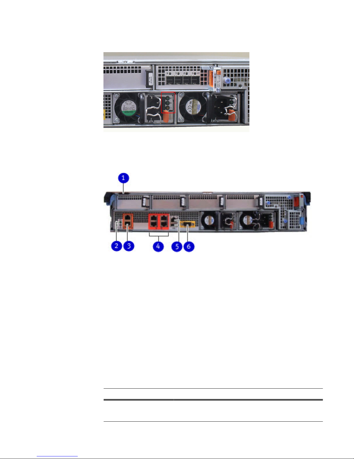
Figure 5 Power supply unit LEDs
Onboard interfaces and LEDs
Figure 6 Onboard interfaces and LEDs
1. Serial number label.
2. SP power LED (top); SP service LED (bottom).
3. Dual-port 10GBaseT.
4. Quad-port Gigabit Ethernet.
5. Service network port (top); USB port (bottom).
6. Serial port.
The onboard interfaces and LEDs are located at the far lower left side of the back of
the system. The onboard interfaces enable you to check system status and connect to
the system through a serial console or Ethernet connections. The dual-port 10GBaseT
and quad-port Gigabit Ethernet interfaces allow connectivity to the data host.
A USB port enables the system to boot from a USB flash device.
Rear LED status summary
Table 5
Indicator status
Part State
SP service Blue indicates normal operation. Amber indicates fault.
SP power Steady green indicates normal power. Dark indicates no power.
System Installation and Setup Guide
Onboard interfaces and LEDs 9
Page 10

Table 5 Indicator status (continued)
Part State
I/O module Steady green indicates normal operation. Amber indicates fault
or failure.
Power supply AC Glows green when AC input is operational.
Power supply DC Glows green when DC output is operational.
Power supply symbol “!” Glows solid amber for fault or attention.
I/O modules and slot assignments
Table 6 CloudBoost 100 slot assignments
Slot Number CloudBoost 100 System
0 Empty
1 Empty
2 Empty
3 SAS or empty
4 NVRAM-BBU
When a system is upgraded, the newly inserted I/O module must go into slot position
three. No other slot positions should be used. Existing modules should not be removed
and reinserted into different slots.
Internal system components
The photo shows the system with the storage processor (SP) module removed from
the chassis. The top of the photo shows the rear of the system.
Installation and Setup Guide
10 EMC CloudBoost 100 2.0 Installation and Setup Guide
Page 11

Figure 7 Top view of SP module (CloudBoost 100 system shown)
Cooling fans
A system processor module contains seven cooling fans. The fans provide cooling for
the processor, DIMMs, and I/O modules. A system can run with one fan module
faulted.
Figure 8
Top view of SP module with air ducts removed
DIMM modules
CloudBoost 100 systems can contain either 4 x 8 GB or 8 x 8 GB memory DIMMs.
System Installation and Setup Guide
Internal system components 11
Page 12

Unpack the system
Procedure
1. Open the “Open Me First” box.
2. Remove the accessories and rack-mount kit from the shipping packages.
3. Remove the controller and bezel from the shipping packages.
Install the rack brackets
CloudBoost 100 systems are installed into racks using the rack bracket hardware.
Bracket hardware
The rack-mounting kit is compatible with racks that have front-to-rear post spacing
between 18 inches and 36 inches. The kit will fit the following types of mounting
holes:
l
7.1 mm round holes
l
.375 inch / 9.2 mm square holes
l
M5, M6, 12-24, and 10-32 threaded holes
The kit includes the following items:
l
Two bracket assemblies, one marked for the left (L) side and one marked for the
right (R) side of the rack.
Figure 9
Bracket assembly
1. Front.
2. Back.
Installation and Setup Guide
12 EMC CloudBoost 100 2.0 Installation and Setup Guide
Page 13

Figure 10 Bracket assembly adapter screws and orientation marking
1. Adapter screws.
2. “L” for left side.
l
Gap filler (2)
Figure 11
Gap filler
l
Assorted screws.
l
One multipurpose screwdriver.
Install the brackets onto the rack
Before you begin
Note
l
Do not hold the bracket assembly in a vertical position as the parts may separate.
l
The CloudBoost 100 system is two rack units (RU) tall. Make sure the location in
the rack fits the product.
Procedure
1. If your rack contains round unthreaded or square holes, skip to the next step. If
your rack contains threaded holes, unscrew and remove the screw caps at both
ends of each bracket.
System Installation and Setup Guide
Install the brackets onto the rack 13
Page 14

Figure 12 Rear screw caps (for threaded hole racks)
Note
The rear guide pin is shown between the two screw caps.
1. Bracket screw caps.
Figure 13
Remove front screw caps
2. As needed, select the bracket marked right or left. Orientation assumes you are
facing the front of the rack. The rear of the bracket contains an adjustable
piece.
Installation and Setup Guide
14 EMC CloudBoost 100 2.0 Installation and Setup Guide
Page 15

Figure 14 Rack bracket
1. Front.
2. Back.
3. From the rear of the system, hold the bracket against the inside of the rack
posts. Align the rear guide pin and slide the bracket towards the front.
CAUTION
If the bracket is mounted in holes that are not vertically aligned from front
to back, the bracket may be damaged and mounting will not be secure.
4. Pull the adjustable sliding part of the bracket towards the front until it is close
to, but not touching, the front of the rack. The bracket adjusts to fit most
racks.
5. Attach the bracket to the rear of the rack using the furnished screws. There are
six holes. Add screws to the second and fifth holes.
Note
If more convenient, you may attach the second bracket while still at the rear of
the rack.
6. If your rack contains threaded holes, add a gap filler to the front end of the
bracket at the front of the system. Otherwise, skip to the next step.
7. Attach the bracket (along with the gap filler, if applicable) to the front of the
rack. There are five holes in the front. Add a screw to the fourth hole. See the
photo.
System Installation and Setup Guide
Install the brackets onto the rack 15
Page 16
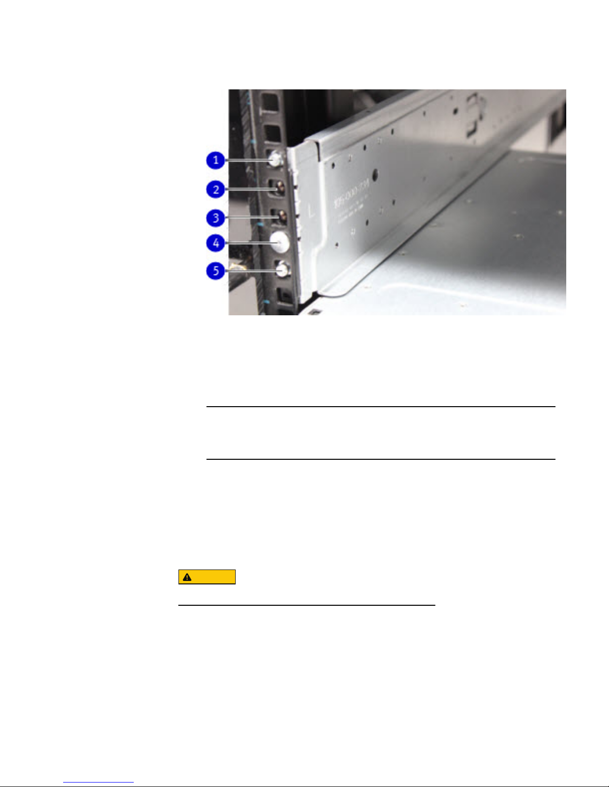
Figure 15 Attach bracket to front of rack
1. Hole for top register pin on the system.
2. Hole for captive screw on the system.
3. Add a second, optional screw to secure the system.
4. Attach the rail to the rack using a provided screw.
5. Hole for bottom register pin on the system.
Note
The optional screw is used to secure the system to the rack if it is necessary to
move the rack.
8. Verify that the bracket is level.
9. Repeat the steps to attach the remaining bracket to the other side of the rack.
10. After installing both brackets, make sure that they are level with one another.
Install the system in the rack
CAUTION
This procedure requires two people or a mechanical lift.
Procedure
1. With the system in the front of the rack, orient the system correctly with the
rack. Carefully lift the system to engage the rack at the required height.
2. Align the rear of the chassis with the lip of each installed rack bracket.
3. Carefully slide the chassis all the way into the rack.
4. At the front, attach the system to each installed bracket using the two captive
screws on the front of the system.
Installation and Setup Guide
16 EMC CloudBoost 100 2.0 Installation and Setup Guide
Page 17
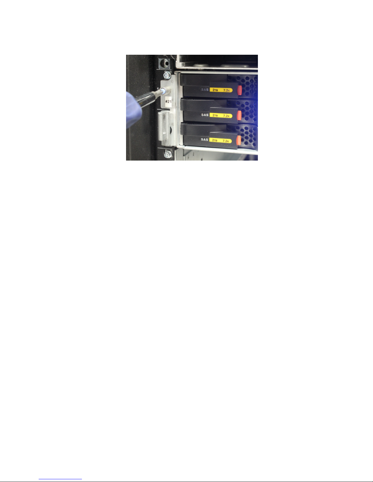
Figure 16 Left captive screw
System Installation and Setup Guide
Install the system in the rack 17
Page 18

Install the cable management arm (CMA)
Procedure
1. Holding the CMA upright, slide the silver brackets on either side of the CMA
over the extension on the rear of each rack rail.
Figure 17 Installing the CMA
1. CMA bracket.
2. Blue plunger button.
3. Rear extension of the system rail.
Figure 18
CMA bracket engaged with rear of rail
2. The blue-colored plunger button should click into place, locking the CMA
bracket to the rail.
3. To adjust the CMA position up or down, pull on the orange latches and pull up or
down on the arm as needed.
Installation and Setup Guide
18 EMC CloudBoost 100 2.0 Installation and Setup Guide
Page 19
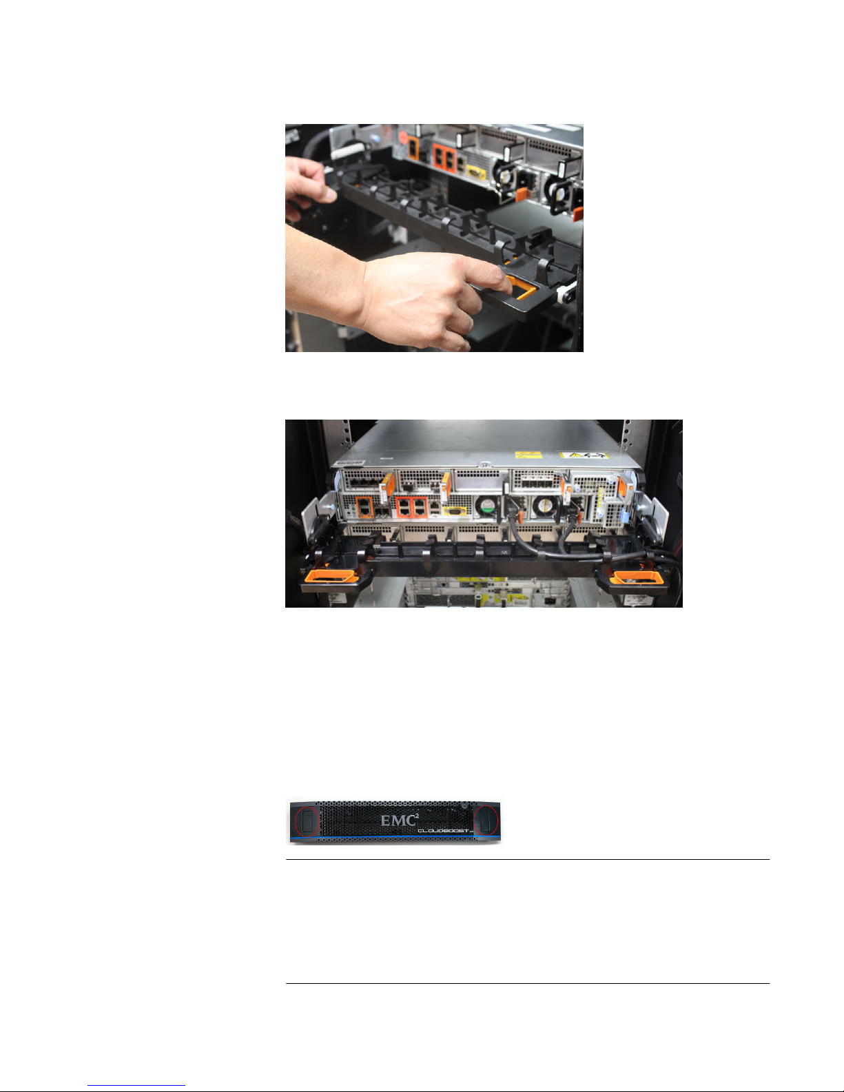
Figure 19 Adjusting the position of the CMA
4. Organize the cables as needed.
Figure 20 Cables organized on CMA
Install the bezel
Procedure
1. Depress the two handhold positions.
2. Push the bezel into place on the front of the chassis, making sure the handhold
locks click into place.
Figure 21
Front bezel
Note
l
The bezel contains a lock and is shipped with a key. If desired, lock the bezel
in place.
l
Push on the two handhold positions to remove the bezel as needed.
System Installation and Setup Guide
Install the bezel 19
Page 20

Connecting data cables
Procedure
1. Enable data transfer Ethernet connectivity. Repeat for each connection.
If using Action
1 Gb copper Ethernet Attach a Cat 5e or Cat 6 copper Ethernet
cable to an RJ-45 Ethernet network port (start
with ethMa and go up).
1 Gb fiber Ethernet Use multimode fiber cables with LC
connectors.
10 Gb copper Ethernet with
an SFP+ connector
Use a qualified SFP+ copper cable.
10 Gb fiber Ethernet Use MMF-850nm cables with LC duplex
connectors.
10GBaseT connections Use Cat 6a S-STP Ethernet cables.
Powering on the controller
Procedure
1. Connect the power cables to each receptacle, and attach the retention clips.
The system immediately powers on when plugged in.
2. Ensure that each power supply is connected to a different power source.
Note that:
l
A new BBU may take up to three hours to charge to a sufficient level before
the file system is enabled.
l
If the battery is good, but the system will not boot, or if the battery is failing
to charge, contact EMC Technical Support.
Requirements for configuring CloudBoost
Perform these tasks before you provide basic IP address information at the CLI.
l
Obtain the necessary credentials for your cloud storage profile, such as the
endpoint URL, the token ID or access key, and the secret key. For more
information, see #unique_34.
l
Determine the fully qualified domain name for your CloudBoost deployment.
l
Obtain a static IP or reserved DHCP address for the CloudBoost appliance and
determine the subnet mask, the gateway, and create forward and reverse DNS
records.
l
Register the CloudBoost hostname/IP address in DNS. The hostname/IP address
must be statically registered in DNS regardless of any mappings created by DHCP.
Failure to do this may result in indeterministic service unavailability and downtime.
Installation and Setup Guide
20 EMC CloudBoost 100 2.0 Installation and Setup Guide
Page 21

l
Open the necessary ports. For more information, see Firewall port requirements on
page 21.
l
By default, CloudBoost uses a self-signed SSL certificate. But if you intend to use
a publicly signed certificate, you should plan and prepare your SSL Certificate
usage for testing and production environments.
Firewall port requirements
As with all networked software solutions, adhering to best practices for security is
encouraged to protect your deployment. If these ports are not configured before you
configure the CloudBoost appliance, reboot the CloudBoost appliance.
Note
It is not recommended to route outbound http traffic from the CloudBoost appliance
through a proxy. This can create a performance bottleneck. In environments where
outbound http traffic is restricted, it is recommended to create an exception for the
appliance in the firewall after consultation with the IT security team.
Table 7 Firewall port requirements
Out In TCP Port Description
Administrator
workstation
CloudBoost appliance 22 SSH for maintenance and
troubleshooting
CloudBoost appliance
l
Cloud storage
(public or private)
l
Cloud Portal
l
Ubuntu upgrade
server
l
CloudBoost
upgrade server
443
l
HTTPS to access object
store (if supported)
l
HTTPS to Cloud Portal and
Cloud PortalServices/APIs
l
https://mirrors.kernel.org
This software is required
only for initial configuration.
It is not used during normal
operations.
l
https://upgradeprd.s.objectstorage.io
This software is required
when the CloudBoost
appliance upgrades
Administrator
workstation
CloudBoost appliance 4444 HTTPS to local appliance
administration page that is used
by support for troubleshooting
NetWorker server CloudBoost appliance 7937–7999 When NetWorker is deployed
with CloudBoost, this is
necessary for various
NetWorker services
CloudBoost appliance ECS storage 9020–9021 Optional
CloudBoost appliance ESRS gateway 9443 Communication from
CloudBoost appliance to the
Secure Remote Services
gateway
System Installation and Setup Guide
Firewall port requirements 21
Page 22

For information about firewall ports for any system being deployed with CloudBoost,
refer to the documentation for that system.
For information about NetWorker, refer to the
NetWorker Security Configuration Guide
.
Configuring network settings for a CloudBoost appliance
You must provide basic network settings information for a CloudBoost appliance at the
Command Line Interface (CLI) before you can register it and complete initial
configuration in the Cloud Portal.
Note
The CloudBoost AMI automatically uses the default VPC settings for the appliances IP
address, DNS, and FQDN.
If you change these network settings, use the following commands.
Procedure
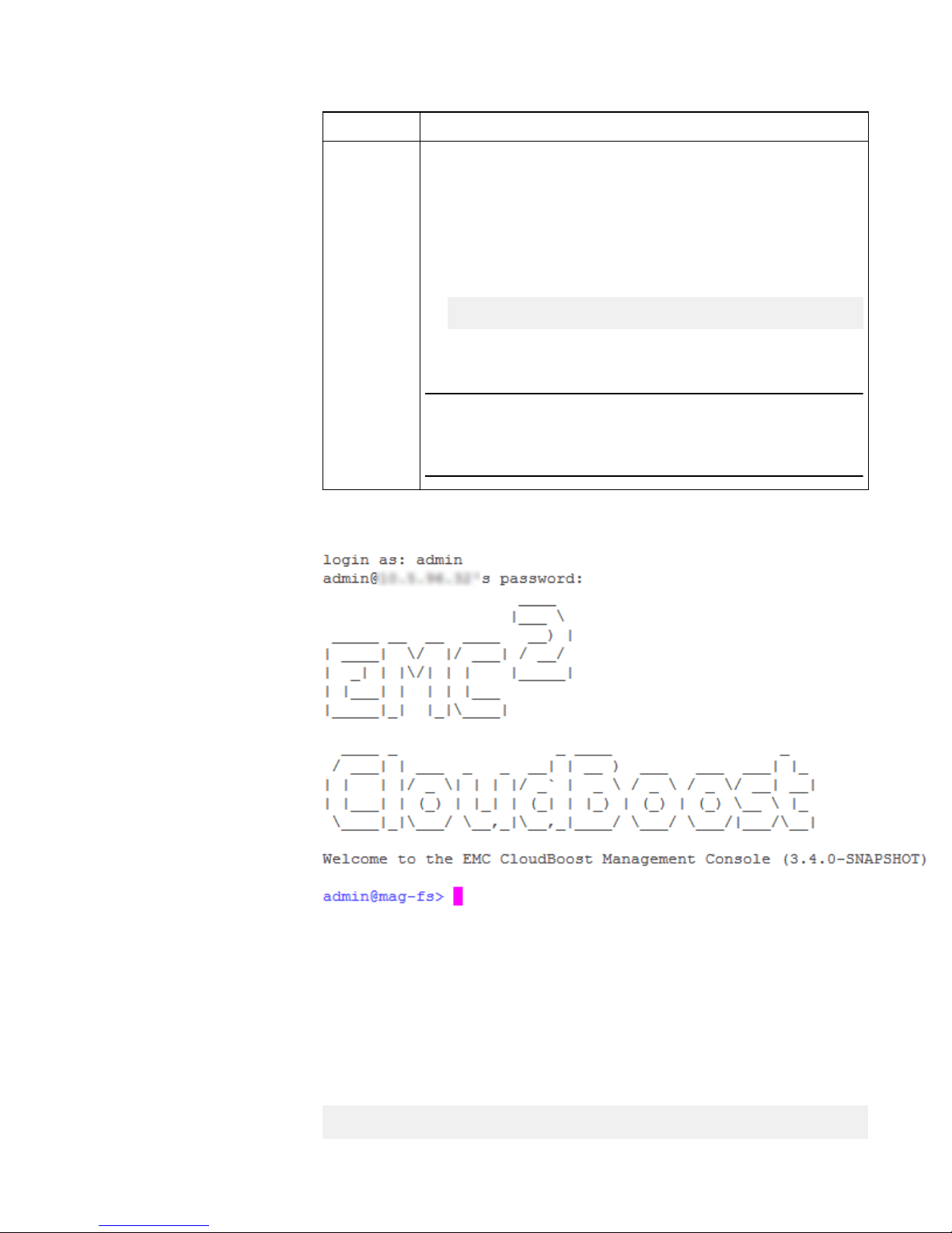
1. Open a CLI window on the CloudBoost appliance.
Option Description
Physical
appliance
Connect to the physical appliance with a serial cable.
vSphere
client
In the vSphere client, right-click VM > Open Console.
EC2
a. Log in to EC2, select the CloudBoost appliance, and then
click Connect.
b. In the Connect To Your Instance wizard, choose whether to
connect with an SSH client or from the browser, and then
follow the instructions.
c. In the SSH terminal, run this command,
ssh -i "private key" admin@AWS FQDN or IP
where
private key
is the private key you used as the key pair
when you installed your CloudBoost AMI.
Note
It is usually better to keep the DHCP configuration supplied by
Amazon because of the more limited configuration options.
Option Description
Physical
appliance
Connect to the physical appliance with a serial cable.
vSphere
client
In the vSphere client, right-click VM > Open Console.
Installation and Setup Guide
22 EMC CloudBoost 100 2.0 Installation and Setup Guide
Page 23
Option Description
EC2
a. Log in to EC2, select the CloudBoost appliance, and then
click Connect.
b. In the Connect To Your Instance wizard, choose whether to
connect with an SSH client or from the browser, and then
follow the instructions.
c. In the SSH terminal, run this command,
ssh -i "private key" admin@AWS FQDN or IP
where
private key
is the private key you used as the key pair
when you installed your CloudBoost AMI.
Note
It is usually better to keep the DHCP configuration supplied by
Amazon because of the more limited configuration options.
The CloudBoost CLI appears.
Figure 22 CLI for CloudBoost
2. Authenticate with the default password, password.
3. Set the new administrator password.
4. To see the current network configuration of the appliance, run this command.
status
System Installation and Setup Guide
Configuring network settings for a CloudBoost appliance 23
Page 24

The status command also shows the Ethernet interfaces to use in the net
config command.
admin@mag-fs> status
Host Configuration:
Hostname: hostname
Domain: domain
FQDN: fqdn
Version Information:
Version: version identifier
Revision: revision identifier
Network Interfaces:
name mode address
netmask
---- ---- -------
------ eth0 dhcp 10.5.96.123 address
Network Routes:
prefix netmask gateway
------ ------- ------ default 0.0.0.0 10.5.96.1
10.5.96.0 address *
DNS Configuration
DNS Servers: 10.5.96.91
Appliance status: Not yet registered
Domain name: domain name
5. For CloudBoost 2.1, if the network interface card was not configured when the
CloudBoost appliance was installed in the ESX server, run the following
command to add a new virtual LAN on the appliance:
net create interface interface vlan vlan_id
6. To statically set the IP address and netmask, run these commands.
If you have multiple networks, you must run this command for each network
that is listed in the status command.
l
For CloudBoost 2.1:
net config interface static IP address netmask netmask
address
For example,
net config eth0 10.5.96.123 netmask 0.0.0.0
l
For CloudBoost 2.0:
ip-address static <ip_address> netmask <netmask> gateway
<gateway>
7. For CloudBoost 2.1, manually add the gateway by running these commands.
Installation and Setup Guide
24 EMC CloudBoost 100 2.0 Installation and Setup Guide
Page 25

If you have multiple networks, you must also add multiple routes to the
gateways.
route add IP address netmask netmask address gw gateway
address
For example,
route add 0.0.0.0 netmask 0.0.0.0 gw 10.5.96.1
8. To manually set the DNS, type these commands:
dns set primary primary IP address
dns set secondary secondary IP address
dns set tertiary tertiary IP address
For example:
dns set primary 10.5.96.91
dns set secondary 10.5.96.92
dns set tertiary 10.5.96.93
9. To set the FQDN, type this command:
fqdn servername.yourcompanydomain
Note
The FQDN must be in lowercase.
For example:
fqdn cloudboost.example.com
10. To verify the networking setup and see the status of the appliance, type this
command:
status
For example:
admin@mag-fs> status
Host Configuration:
Hostname: hostname
Domain: domain
FQDN: fqdn
Version Information:
Version: version identifier
Revision: revision identifier
Network Interfaces:
name mode address
netmask
System Installation and Setup Guide
Configuring network settings for a CloudBoost appliance 25
Page 26

---- ---- -------
------ eth0 static 10.5.96.123
address
Network Routes:
prefix netmask gateway
------ ------- ------ default 0.0.0.0 10.5.96.1
0.0.0.0 address *
DNS Configuration
DNS Servers: 10.8.192.91
Appliance status: Not yet registered
Domain name: domain name
Results
After you have verified the system's basic networking settings, you can register the
appliance and then configure CloudBoost by using the EMC Cloud Portal.
Note
Other commands are also available from the command line. To get help, type help
or ?.
CloudBoost appliance cache sizing
If you intend to enable the site cache for a CloudBoost appliance, change the data disk
size before initial configuration of the CloudBoost appliance at the CLI.
Change the parameters in vCenter virtual machine configurations before you begin
initial CloudBoost configuration at the CLI. It is recommended that you change these
numbers to the appropriate levels based on the amount of data you plan to backup.
Consider the following:
l
The ingestion rate for a CloudBoost appliance without site cache enabled is
measured at up to 100 MB/s.
l
The site cache has a 50 MB/s ingestion rate for the 32 TB physical appliance.
l
The site cache has a 25 MB/s ingestion rate for all other appliances that can be
improved by de-duplication and compression, depending on the workload.
l
The underlying storage rate must be 25 MB/s for simultaneous reading and
writing.
l
An average chunk size of 256 KB equals a few hundred IOPS.
l
The total number of site cache disks must be a multiple of 2 up to 32 disks. For
example 1, 2, 4, 8, 16 or 32 disks.
l
To optimize performance, configure each site cache VMDK on a different data
store. For example, for a 2TB site cache 4x500GB VMDKs can be used.
l
The size of the cache cannot be increased or decreased by growing the existing
data disk size in vCenter.
l
The minimum size of the cache is 200 GB, and can be increased up to 6 TB on the
virtual appliance by adding disks that match the size of the existing site cache
disks.
l
The cache is firewall-friendly, so multiple ports do not need to be opened.
Installation and Setup Guide
26 EMC CloudBoost 100 2.0 Installation and Setup Guide
Page 27

Note
If higher ingestion speeds occur when connecting directly to the cloud store, do not
use the cache. The backups might exceed the capacity of the cache.
Table 8 ESX site cache minimum requirements
Work
Flow Type
Site
Cache
CPU Memory OS Metadata Site
Cache
Size
Backup/
Clone
Yes 16 64 GB 41 GB 100 GB 200 GB
System Installation and Setup Guide
CloudBoost appliance cache sizing 27
Page 28

Copyright © 2015 EMC Corporation All rights reserved.
Published November 2015
Dell believes the information in this publication is accurate as of its publication date. The information is subject to change without notice.
THE INFORMATION IN THIS PUBLICATION IS PROVIDED “AS-IS.“ DELL MAKES NO REPRESENTATIONS OR WARRANTIES OF ANY KIND WITH
RESPECT TO THE INFORMATION IN THIS PUBLICATION, AND SPECIFICALLY DISCLAIMS IMPLIED WARRANTIES OF MERCHANTABILITY OR
FITNESS FOR A PARTICULAR PURPOSE. USE, COPYING, AND DISTRIBUTION OF ANY DELL SOFTWARE DESCRIBED IN THIS PUBLICATION
REQUIRES AN APPLICABLE SOFTWARE LICENSE.
Dell, EMC, and other trademarks are trademarks of Dell Inc. or its subsidiaries. Other trademarks may be the property of their respective owners.
Published in the USA.
Installation and Setup Guide
28 EMC CloudBoost 100 2.0 Installation and Setup Guide
 Loading...