

Page 1

EMC Corporation
Corporate Headquarters:
Hopkinton, MA 01748
-9103
1
-508-435-1000
www.EMC.com
EMC CLARiiON
DAE2P and DAE3P Disk-Array Enclosures
HARDWARE REFERENCE
P/N 300-002-407
REV A04
Page 2

DAE2P/DAE3P Hardware Reference
ii
Copyright © 2005 - 2006 EMC Corporation. All rights reserved.
Published August, 2006
EMC believes the information in this publication is accurate as of its publication date. The
information is subject to change without notice.
THE INFORMATION IN THIS PUBLICATION IS PROVIDED “AS IS.” EMC CORPORATION
MAKES NO REPRESENTATIONS OR WARRANTIES OF ANY KIND WITH RESPECT TO THE
INFORMATION IN THIS PUBLICATION, AND SPECIFICALLY DISCLAIMS IMPLIED
WARRANTIES OF MERCHANTABILITY OR FITNESS FOR A PARTICULAR PURPOSE.
Use, copying, and distribution of any EMC software described in this publication requires an
applicable software license.
For the most up-to-date listing of EMC product names, see EMC Corporation Trademarks on
EMC.com.
All other trademarks used herein are the property of their respective owners.
Page 3
DAE2P/DAE3P Hardware Reference
iii
Regulatory Notices Product Type(s) KTN-STL, KTN-STL4
This device complies with Part 15 of the FCC rules. Operation is subject to the following two conditions:
(1) this device may not cause harmful interference, and (2) this device must accept any interference received,
including interference that may cause undesired operation.
Testing was done with shielded cables. Therefore, in order to comply with the FCC regulations, you must use shielded
cables with your installation. Changes or modifications to this unit not expressly approved by the party responsible
for compliance could void the user's authority to operate the equipment.
This equipment has been tested and found to comply with the limits for a Class A digital device, pursuant to Part 15
of the FCC Rules. These limits are designed to provide reasonable protection against harmful interference in a
commercial environment. This equipment generates, uses, and can radiate radio frequency energy and, if not
installed and used in accordance with the instruction manual, may cause harmful interference to radio
communications. Operation of this equipment in a residential area is likely to cause harmful interference in which
case the user will be required to correct the interference at his own expense.
This Class A digital apparatus complies with Canadian ICES-003
Cet appareil numérique de la classe A est conforme à la norme NMB-003 du Canada
Manufacturer’s Declaration of Conformity - CE mark
This equipment has been tested and found to comply with the requirements of European Community Council
Directives 89/336/EEC, 73/23/EEC, and 98/68/EEC relating to electromagnetic compatibility and product safety
respectively.
This product complies with EN55022, CISPR22 and AS/NZS CISPR22 Class A.
This is a Class A product. In a domestic environment this product may cause radio interference in which case the user
may be required to take adequate measures.
Page 4

DAE2P/DAE3P Hardware Reference
iv
Standards Certification and Compliance
Rackmount disk enclosures are tested and certified for compliance with the international environmental and safety
specifications listed below and marked to indicate such compliance and certification as required.
EMI Standards
Standard Description
CSA 22.2 60950 3rd
Edition
Safety of Information Technology Equipment including Electrical
Business Equipment
TUV GS EN 60950-2000
UL 60950 3rd Edition
GOST
CE Mark European EMC Directive & Low Voltage Directive Requirements
Standard Description
FCC Part 15 Class A, Radio Frequency Device Requirements
ICES-003 Class A, Interference-Causing Equipment Standard - Digital
Apparatus
CE Mark European EMC Directive & Low Voltage Directive Requirements.
VCCI Class A, Voluntary Control Council for Interference
AS/NZS CISPR22 Class A, Electromagnetic Interference - Limits & Methods of
Measurement of ITE
CNS13438 BSMI EMC Requirements
Page 5

DAE2P/DAE3P Hardware Reference
v
Preface............................................................................................................................. ix
Warnings and cautions.......................................................................................... xiii
Chapter 1 About DAE2P and DAE3P disk enclosures
Introduction...................................................................................... 1-2
Link Control Cards (LCCs)............................................................. 1-8
Disk modules.................................................................................... 1-9
Power supply/system cooling modules .................................... 1-11
Chapter 2 Installing a DAE2P/DAE3P
Requirements.................................................................................... 2-2
Installing a disk enclosure in a cabinet ......................................... 2-3
Setting up an installed disk enclosure .......................................... 2-4
Connecting AC Power..................................................................... 2-5
Setting the enclosure address....................................................... 2-10
Connecting the DAE2P/DAE3P to the back end bus............... 2-12
Binding disk modules into RAID groups................................... 2-15
Chapter 3 Servicing a DAE2P/DAE3P
Monitoring disk enclosure status .................................................. 3-2
Handling FRUs................................................................................. 3-6
Replacing or adding a disk module............................................ 3-10
Replacing an LCC module............................................................ 3-17
Replacing a power supply/system cooling module................. 3-20
Contents
Page 6

DAE2P/DAE3P Hardware Reference
vi
Contents
Appendix A Technical specifications
Enclosure specifications ................................................................ A-2
Operating limits ............................................................................. A-5
Index................................................................................................................................ i-1
Page 7

DAE2P/DAE3P Hardware Reference
vii
1-1 DAE2P/DAE3P ............................................................................................. 1-2
1-2 DAE2P/DAE3P front LED display ............................................................ 1-4
1-3 DAE2P/DAE3P rear components .............................................................. 1-5
1-4 Disk enclosure rear view — LEDs and connectors .................................. 1-5
1-5 Disk enclosure bus and address indicators ............................................... 1-6
1-6 Disk enclosure front bezel ............................................................................ 1-7
1-7 LCC connectors and status LEDs ................................................................ 1-8
1-8 Disk modules ............................................................................................... 1-10
1-9 Power/cooling module LEDs .................................................................... 1-12
2-1 Plugging in the AC line cords ..................................................................... 2-5
2-2 Connecting DAE2P power cords (CX300/CX500 storage system) ........ 2-7
2-3 Connecting DAE3P power cords (CX3-80 storage system) .................... 2-8
2-4 Setting the enclosure address (EA) ........................................................... 2-11
2-5 Connecting a disk enclosure to another FC device ................................ 2-12
2-6 Cabling disk enclosures together — two Fibre Channel buses ............ 2-13
2-7 Cabling DAE2Ps/DAE3Ps together — four Fibre Channel buses ....... 2-14
3-1 Front disk enclosure and disk module status lights (bezel removed) ... 3-2
3-2 Enclosure address and bus ID indicators .................................................. 3-4
3-3 Power/cooling module status indicators .................................................. 3-5
3-4 LCC status LEDs ............................................................................................ 3-5
3-5 Disk module comparison ........................................................................... 3-10
3-6 Unlocking and removing the front bezel ................................................. 3-12
3-7 Removing a disk filler module .................................................................. 3-13
3-8 Removing a disk module ........................................................................... 3-14
3-9 Installing a disk or filler module ............................................................... 3-15
3-10 Installing and locking the front bezel ....................................................... 3-16
3-11 Removing a copper cable from an LCC ................................................... 3-17
3-12 Removing an LCC ....................................................................................... 3-18
Figures
Page 8

DAE2P/DAE3P Hardware Reference
viii
Contents
3-13 Installing an LCC ........................................................................................ 3-18
3-14 Reconnecting a copper cable to an LCC .................................................. 3-19
3-15 Unplugging the AC power cord ............................................................... 3-20
3-16 Removing a power/cooling module ........................................................ 3-21
3-17 Installing a power/cooling module ......................................................... 3-21
3-18 Plugging in the power cord ....................................................................... 3-22
Page 9

DAE2P/DAE3P Hardware Reference
ix
Preface
This manual is your primary source of information about EMC
CLARiiON 2- and 4-gigabit UltraPoint disk-array enclosure (DAE2P
and DAE3P) hardware.
The DAE2P/DAE3P is often called a disk enclosure.
Audience This guide is part of the DAE2P and DAE3P documentation set, and
is intended for use by system administrators and others responsible
for the installation, setup, and maintenance of the product.
Readers of this guide are expected to be familiar with the following
topics:
◆ Storage-system operation
◆ Basic computer hardware safety and maintenance procedures.
Organization The information in this guide is organized as follows:
Chapter 1, “About DAE2P and DAE3P disk enclosures,” provides a
descriptive overview of the disk enclosure.
Chapter 2, “Installing a DAE2P/DAE3P,” describes how to set up and
power up the enclosure(s) in your cabinet.
Chapter 3, “Servicing a DAE2P/DAE3P,” provides instructions and
procedures for recognizing and replacing failed components.
Appendix A, “Technical specifications,” lists operating limits,
shipping and storage requirements, and technical specifications.
Page 10

x
DAE2P/DAE3P Hardware Reference
Preface
Related
documentation
EMC Rails and Enclosures (CX-Series Storage Systems) Field Installation
Guide (P/N 300-001-799)
EMC Rails and Enclosures (CX3-Series Storage Systems) Field Installation
Guide (P/N 300-003-630)
EMC Navisphere Manager Administrator’s Guide (P/N 300-003-511)
Planning your CX3-Series Fibre Channel Storage System Configuration
Available on EMC Powerlink
EMC Navisphere Security Administrator’s Guide (P/N 069001124)
EMC Installation Roadmap for CX3-Series, CX-Series, AX-Series, and
FC-Series Storage Systems (P/N 069001166)
EMC Storage Systems CX-Series Disk and FLARE OE Matrix
(P/N 014003111)
Conventions used in
this guide
EMC uses the following conventions for notes, cautions, warnings,
and danger notices.
A note presents information that is important, but not hazard-related.
CAUTION
!
A caution contains information essential to avoid data loss or
damage to the system or equipment. The caution may apply to
hardware or software.
WARNING
A warning contains information essential to avoid a hazard that can
cause severe personal injury, death, or substantial property damage
if you ignore the warning.
DANGER
A danger notice contains information essential to avoid a hazard
that will cause severe personal injury, death, or substantial property
damage if you ignore the message.
Page 11

DAE2P/DAE3P Hardware Reference
xi
Preface
Typographical conventions
This manual uses the following format conventions:
Finding current
information
The most up-to-date information about the DAE2P and DAE3P is
posted on the EMC Powerlink website. We recommend that you
download the latest information before you install or service your
enclosure. If you purchased this product from an EMC reseller and
you cannot access Powerlink, the latest product information should
be available from your reseller.
To access EMC Powerlink, use the following link:
http://Powerlink.EMC.com
After you log in, select Support > Documentation/White Paper
Library and find the following:
◆ The FLARE™ software release notes
◆ The latest version of this reference.
This
typeface
Indicates text (including punctuation) that you type
verbatim, all commands, pathnames, filenames,
and directory names. It indicates the name of a
dialog box, field in a dialog box, menu, menu
option, or button.
This typeface Represents variables for which you supply the
values; for example, the name of a directory or file,
your username or password, and explicit
arguments to commands.
This
typeface
Represents a system response (such as a message or
prompt), a file or program listing.
x > y
Represents a menu path. For example, Operations
> Poll All Storage Systems tells you to select Poll
All Storage Systems on the Operations menu.
[ ]
Encloses optional entries.
|
Separates alternative parameter values; for
example:
LUN-name | LUN-number means you can use either
the LUN-name or the LUN-number.
Page 12

xii
DAE2P/DAE3P Hardware Reference
Preface
◆ EMC Installation Roadmap for CX3-Series, CX-Series, AX-Series, and
FC-Series Storage Systems, which provides a checklist of the tasks
that you must complete to install your storage system in a storage
area network (SAN) or direct attach configuration.
Where to get help EMC support, product, and licensing information can be obtained as
follows.
Product information — For documentation, release notes, software
updates, or for information about EMC products, licensing, and
service, go to the EMC Powerlink website (registration required) at:
http://Powerlink.EMC.com
Technical support — For technical support, go to EMC WebSupport
on Powerlink. To open a case on EMC WebSupport, you must be a
WebSupport customer. Information about your site configuration and
the circumstances under which the problem occurred is required.
Your comments Your suggestions will help us continue to improve the accuracy,
organization, and overall quality of user publications. Please send a
message to techpub_comments@emc.com with your opinions of this
manual.
Page 13

DAE2P/DAE3P Hardware Reference
xiii
The following warnings and cautions pertain throughout this guide.
WARNING Trained service personnel only
Ground circuit continuity is vital for safe operation of the machine.
Never operate the machine with grounding conductors disconnected.
Remember to reconnect any grounding conductors removed for or
during any installation procedure.
ATTENTION Resérvé au personnel autorisé.
Un circuit de terre continu est essentiel en vue du fonctionnement
sécuritaire de l'apareil. Ne jamais mettre l'appareil en marche lorsque
le conducteur de mise a la terre est débranché.
WARNUNG Nur für Fachpersonal.
STROMSTREUVERLUST: Gerät muss geerdet werden, bevor es am
Stromnetz angeschlossen wird.
Warnings and
cautions
Page 14
xiv
DAE2P/DAE3P Hardware Reference
Warnings and Cautions
WARNING
Trained personnel are advised to exercise great care at all times
when working on the unit. Remember to:
◆ Remove rings, watches, or other jewelry and neckties before
you begin any procedures.
◆ Use caution near any moving part and any part that may start
unexpectedly such as fans, motors, solenoids, and so on.
◆ Always use the correct tools for the job.
◆ Always use the correct replacement parts.
◆ Keep all paperwork, including incident reports, up to date,
complete, and accurate.
Static precautions EMC incorporates state-of-the-art technology in its designs, including
the use of LSI and VLSI components. These chips are very susceptible
to damage caused by static discharge and need to be handled
accordingly.
CAUTION
!
Before handling printed-circuit boards or other parts containing
LSI and/or VLSI components, observe the following precautions:
◆ Store all printed-circuit boards in antistatic bags.
◆ Use a ground strap whenever you handle a printed-circuit
board.
◆ Unless specifically designed for nondisruptive replacement,
never plug or unplug printed-circuit boards with the power on.
Severe component damage may result.
Page 15
DAE2P/DAE3P Hardware Reference
xv
Warnings and Cautions
Replacing the SP battery
A lithium battery on the storage processor powers the real-time clock
(RTC) for three to four years in the absence of power. Only trained
personnel should change or replace this battery.
WARNING
Danger of explosion if battery is incorrectly replaced. Replace only
with the same or equivalent type recommended by the equipment
manufacturer. Discard used batteries according to manufacturer's
instructions.
Page 16

xvi
DAE2P/DAE3P Hardware Reference
Warnings and Cautions
Page 17
About DAE2P and DAE3P disk enclosures
1-1
1
Invisible Body Tag
Topics in this chapter include:
◆ Introduction ........................................................................................1-2
◆ Link Control Cards (LCCs)...............................................................1-8
◆ Disk modules......................................................................................1-9
◆ Power supply/system cooling modules....................................... 1-11
About DAE2P and
DAE3P disk enclosures
Page 18
1-2
DAE2P/DAE3P Hardware Reference
About DAE2P and DAE3P disk enclosures
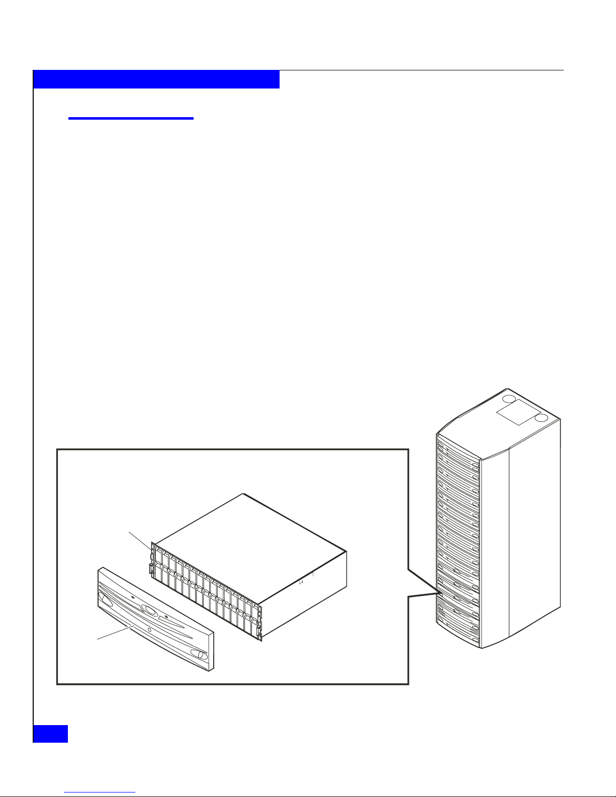
Introduction
EMC® CLARiiON® DAE2P and DAE3P UltraPoint™ (sometimes
called "point-to-point") disk-array enclosures are highly available,
high-performance, high-capacity storage systems that use a Fibre
Channel Arbitrated Loop (FC-AL) as the interconnect interface. An
enclosure connects to another DAE or a CX-series processor, and is
managed by storage-system software in RAID (Redundant Array of
Independent Disk) configurations. The enclosure is only 3U (5.25
inches) high, but can include 15 hard disk drive/carrier modules. Its
modular, scalable design allows for additional disk storage as your
needs increase. The examples and illustrations in this manual show
the rackmounted DAE2P/DAE3P in a standard 40U EMC cabinet.
DAE2P enclosures include high-performance Fibre Channel disk
drives. DAE3P enclosures can include either Fibre Channel or
economical Serial Advanced Technology Attach (SATA 3 Gb/s,
sometimes called SATA II) drives. You can integrate and connect Fibre
Channel and SATA enclosures within a storage system, but you
cannot mix SATA and Fibre Channel components within a DAE3P.
Figure 1-1 DAE2P/DAE3P
EMC2164stil
Disk
Drive
(0 - 14)
Front
Bezel
Rackmount
Cabinet
Page 19

Introduction
1-3
About DAE2P and DAE3P disk enclosures
The DAE2P/DAE3P uses FC-AL link control cards to manage disks
and I/O traffic between enclosures. A DAE2P supports 2- or 4-gigabit
disks and 2-gigabit data transfer to and from disks on a Fibre Channel
loop called a back-end bus. DAE3P enclosures can support 2- or
4-gigabit disk modules and operate at either 2- or 4-gigabit bus speed.
2 Gb processors, enclosures, and disk modules cannot support or operate on
a 4 Gb bus. The DAE2P and DAE3P are externally identical except for
a distinguishing "4GB" label on the back of DAE3P enclosures.
Any DAE2P or DAE3P includes up to fifteen 3.5-inch disk modules.
Simple serial cabling provides easy scalability. You can interconnect
disk enclosures to form a large disk storage system; the number and
size of buses depends on the capabilities of your storage processor.
Highly available configurations require at least one pair of physically
independent loops (A and B sides of bus 0, sharing the same
dual-port disks). Other configurations use two, three, four, or more
buses. You can place the disk enclosures in the same cabinet, or in one
or more separate cabinets. High-availability features are standard.
The DAE2P/DAE3P includes the following components:
◆ A sheet-metal enclosure with a midplane and front bezel
◆ Two link control cards (LCCs)
◆ As many as 15 disk modules
◆ Two power supply/system cooling modules
The power supply and system cooling components of the power/cooling
modules function independently of each other, but the assemblies are
packaged together into a single field-replaceable unit (FRU).
Any unoccupied disk module slot has a filler module to maintain air
flow.
The LCCs, disk modules, power supply/system cooling modules,
and filler modules are field-replaceable units (FRUs), which you can
add or replace without tools while the array is powered up.
The enclosure can continue running with one operating power
supply and a single functional LCC. At least three of the four system
cooling blowers must be running correctly for continuous operation.
Figures 1-2 through1-4 show the disk enclosure components. Details
on each component accompany the figures. Where the enclosure
provides slots for two identical components, the components are
called component-name A or component-name B, as shown in the
illustrations.
Page 20
1-4
DAE2P/DAE3P Hardware Reference
About DAE2P and DAE3P disk enclosures
For increased clarity, the following figures depict the disk enclosure outside
of the rack cabinet. Your disk enclosure may be installed in a rackmount
cabinet as shown in Figure 1-1.
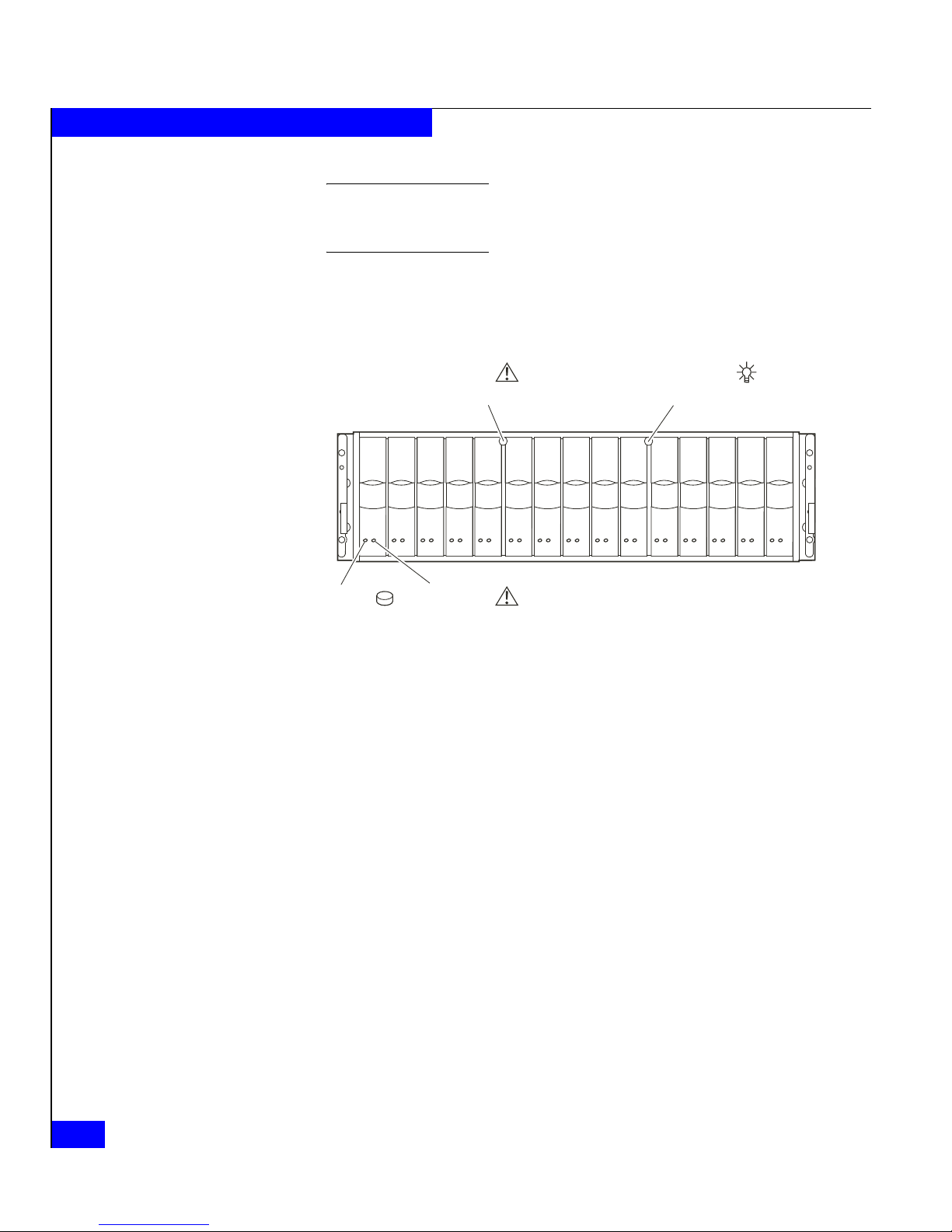
As shown in Figure 1-2, the front LED display contains two status
lights for each disk module, and two disk enclosure status lights. The
enclosure status lights are visible with the front bezel installed.
Figure 1-2 DAE2P/DAE3P front LED display
A blue power LED indicates a DAE3P enclosure operating at four
gigabits per second. The power LED is green in DAE2P enclosures,
and DAE3Ps operating at two Gb.
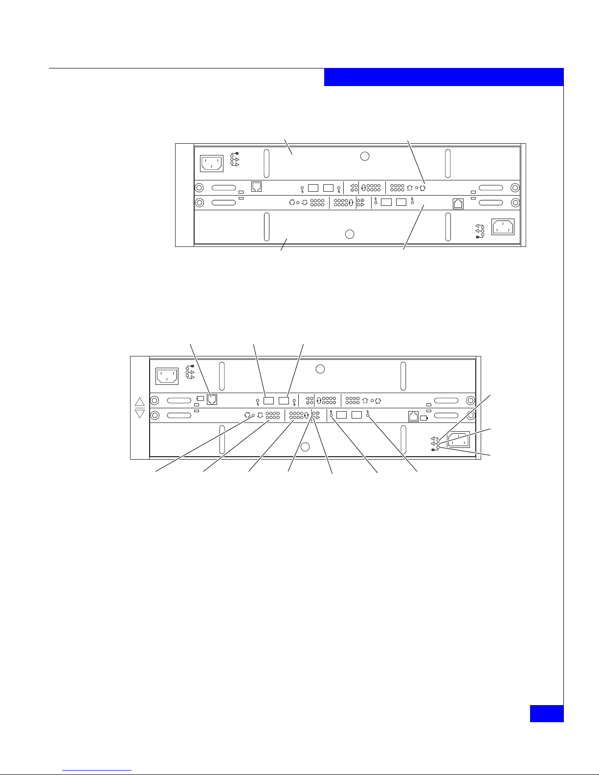
Figure 1-3 and Figure 1-4 show the DAE2P/DAE3P components
visible from the rear of the enclosure. Each highly-available enclosure
includes two link control cards and two power supply/system
cooling (power/cooling) modules.
EMC2166a
Power LED
(Green or Blue)
Fault LED
(Amber)
Fault LED
(Amber)
Disk Activity
LED
(Green)
Page 21
Introduction
1-5
About DAE2P and DAE3P disk enclosures
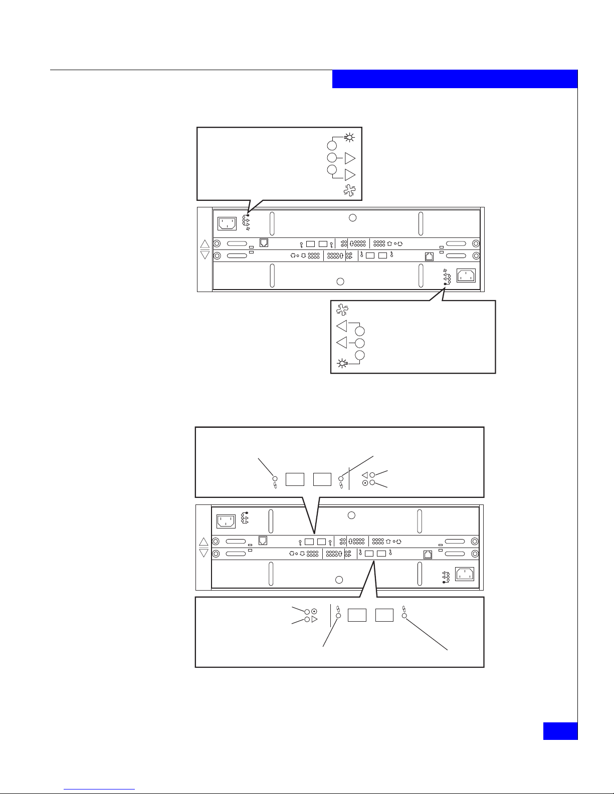
Figure 1-3 DAE2P/DAE3P rear components
Figure 1-4 Disk enclosure rear view — LEDs and connectors
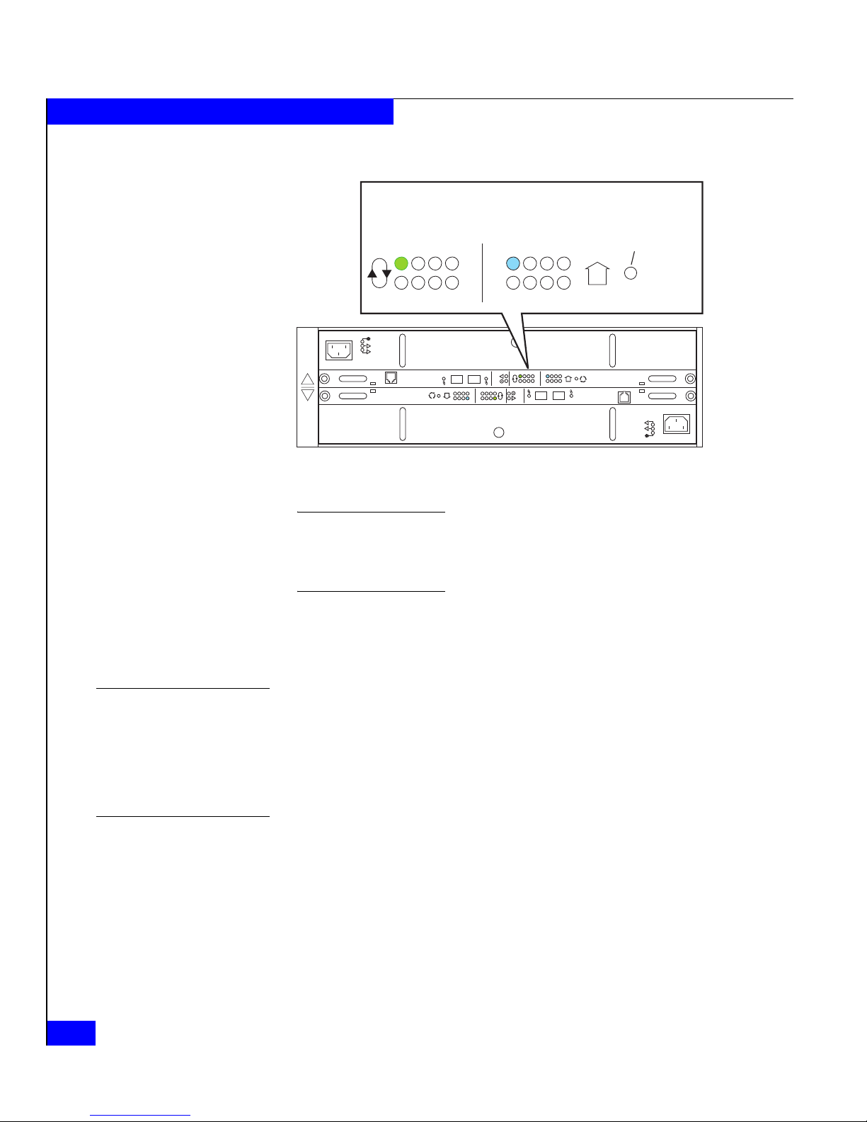
As shown in Figure 1-5, an enclosure address (EA) indicator is
located on each LCC. (The EA is sometimes referred to as an
enclosure ID.) Each link control card (LCC) includes a bus (loop)
identification indicator. The storage processor initializes bus ID when
the operating system loads.
!!
!!
!
EXP PRI
EXPPRI
#
!
EXP PRI
EXPPRI
#
Power/Cooling Module B Link Control Card B
Power/Cooling Module A Link Control Card A
EMC3232
!!
!!
!
EXP PRI
EXPPRI
#
!
EXP PRI
EXPPRI
#
A
B
+
-
+
-
Primary
Link
Active
Expansion
Link
Active
Expansion
(Out)
Primary
(In)
SPS (Not used in
CLARiiON)
Fault
(Amber)
Power
(Green)
Loop
(Bus) ID
Enclosure
Address
EA Selection
Blower
Fault
(Amber)
Power
Fault
(Amber)
Power
EMC3209
Page 22
1-6
DAE2P/DAE3P Hardware Reference
About DAE2P and DAE3P disk enclosures
Figure 1-5 Disk enclosure bus and address indicators
The enclosure address is set at installation. Disk module IDs are numbered
left to right (looking at the front of the unit) and are contiguous throughout
an array: enclosure 0 contains modules 0-14; enclosure 1 contains modules
15-29; enclosure 2 includes 30-44, and so on through eight enclosures.
The enclosure EA switch and bus indicator are described in the
installation procedure in Chapter 2. The status lights are described in
the “Monitoring disk enclosure status” section of Chapter 3.
Midplane
A midplane between the disk modules and the LCC and
power/cooling modules distributes power and signals to all
components in the enclosure. LCCs, power/cooling modules, and
disk drives — the enclosure’s field-replaceable units (FRUs) — plug
directly into the midplane.
Front bezel
The front bezel, shown in Figure 1-6, has a locking latch and an
electromagnetic interference (EMI) shield. You must remove the bezel
!!
!!
!
EXP PRI
EXPPRI
#
!
EXP PRI
EXPPRI
#
A
B
012
3
456
7
012
3
456
7
Bus ID
Enclosure
Address
#
EA Selection
(Press here to
change EA)
EMC3210
Page 23
Introduction
1-7
About DAE2P and DAE3P disk enclosures
to remove and install drive modules. EMI compliance requires a
properly installed front bezel.
Figure 1-6 Disk enclosure front bezel
EMC2173
Page 24
1-8
DAE2P/DAE3P Hardware Reference
About DAE2P and DAE3P disk enclosures
Link Control Cards (LCCs)
An LCC supports and controls one Fibre Channel bus and monitors
the DAE2P/DAE3P.
Figure 1-7 LCC connectors and status LEDs
A blue Link Active LED indicates a DAE3P enclosure operating at four
gigabits. The Link Active LED(s) is green in DAE2P enclosures, and DAE3Ps
operating at two Gb.
The LCCs in a DAE2P/DAE3P connect to other Fibre Channel
devices (processor enclosures, or other DAEs) with twin-axial copper
cables. The cables connect LCCs in a storage system together in a
daisy-chain (loop) topology.
Internally, each DAE2P/DAE3P LCC uses FC_AL protocols to
emulate a loop; it connects to the drives in its enclosure in a
point-to-point fashion through a switch. The LCC independently
receives and electrically terminates incoming FC-AL signals. For
traffic from the system’s storage processors, the LCC switch passes the
input signal from the primary port (PRI) to the drive being accessed;
the switch then forwards the drive's output signal to the expansion
port (EXP), where cables connect it to the next DAE in the loop. (If the
target drive is not in the LCC’s enclosure, the switch passes the input
signal directly to the EXP port.) At the unconnected expansion port
(EXP) of the last LCC, the output signal (from the storage processor)
is looped back to the input signal (to the storage processor). For traffic
directed to the system's storage processors, the switch passes input
!!
!!
!
EXP PRI
EXPPRI
#
!
EXP PRI
EXPPRI
#
A
B
EMC3226_revised
Expansion Link
Active LED (Green/Blue)
Primary Link
Active LED (Green/Blue)
Fault LED (Amber)
Power LED (Green)
!
EXP PRI
EXPPRI
Page 25

Disk modules
1-9
About DAE2P and DAE3P disk enclosures
signals from the expansion port directly to the output signal of the
primary port.
Each LCC independently monitors the environmental status of the
entire enclosure, using a microcomputer-controlled FRU
(field-replaceable unit) monitor program. The monitor communicates
status to the server, which polls disk enclosure status. LCC firmware
also controls the LCC port bypass circuits and the disk-module status
lights.
LCCs do not communicate with or control each other.
Each LCC has four status lights. These status lights are described in
“Monitoring disk enclosure status,” in Chapter 3.
Captive screws on the LCC lock it into place to ensure proper
connection to the midplane. You can add or replace an LCC while the
disk enclosure is powered up.
Disk modules
Each disk module consists of one disk drive in a carrier. You can add
or remove a disk module while the DAE2P/DAE3P is powered up,
but should exercise special care when removing modules while they
are in use.
DAE2P and DAE3P disk modules support dual-port FC-AL
interconnects through the two LCCs and their cabling; SATA
modules include a paddle card that provides a bridge between Fibre
Channel and SATA signals.
With some configuration restrictions, you can integrate and connect Fibre
Channel and ATA (Advanced Technology Attachment) DAE2 enclosures
with DAE2P/DAE3Ps within a storage system, but you cannot use ATA disks
within a DAE2P or DAE3P. (DAE3P SATA disks will not work in a
DAE2-ATA enclosure.)
A DAE3P enclosure can include Fibre Channel or SATA disk
modules, but not both types; DAE2P enclosures do not support SATA
disk modules.You can visually distinguish between module types by
their different latch and handle mechanisms and by labels on each
module. 4 Gb Fibre Channel drive carriers include a label that
indicates they can operate at 2/4 Gb; 2 Gb drive labels list capacity
and spindle speed only. SATA drive labels list type, capacity, and
Page 26

1-10
DAE2P/DAE3P Hardware Reference
About DAE2P and DAE3P disk enclosures
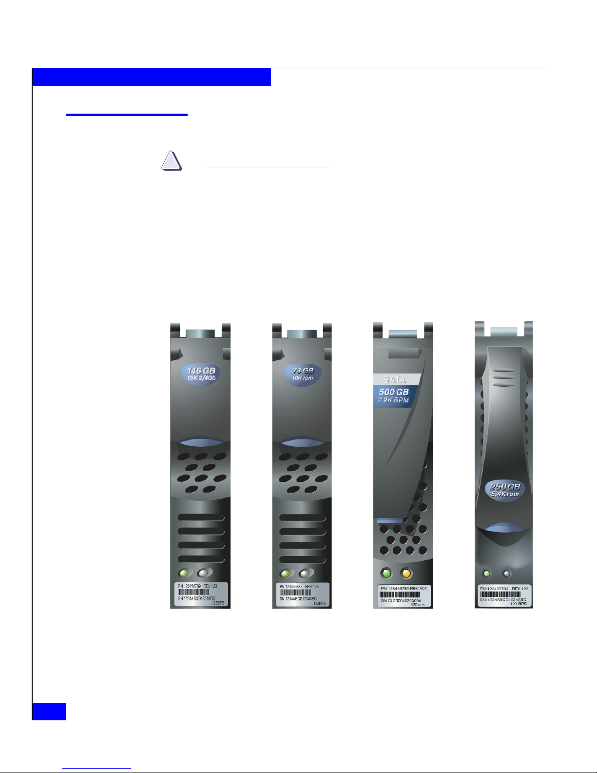
spindle speed. Figure 1-8 shows different disk modules supported in
a DAE2P/DAE3P, and an unsupported ATA module.
Figure 1-8 Disk modules
Disk drives
DAE2P/DAE3P Fibre Channel disk drives conform to FC-AL
specifications and 2 or 4 Gb Fibre Channel interface standards. SATA
disk drives conform to Serial ATA II Electrical Specification 1.0 and
include dual-port SATA interconnects; a paddle card on each drive
provides a 4 Gb Fibre Channel connection for the module.
The 4 Gb drives in a DAE2P will operate at 2 Gb; a DAE3P supports 2
Gb drives only if the entire back-end bus that contains the drives is operating
at 2 Gb. The disk module slots in the enclosure accommodate 1 inch
(2.54 cm) by 3.5 inch (8.75 cm) disk drives.
CL3583
Fibre Channel
2- and 4-Gb
Fibre Channel
2-Gb only
SATA
2- and 4-Gb
ATA
(Not supported
)
Page 27

Power supply/system cooling modules
1-11
About DAE2P and DAE3P disk enclosures
Drive modules are extremely sensitive electronic components. Refer to the
instructions on “Handling FRUs” whenever you handle a disk module.
Drive carrier
The disk drive carriers are metal and plastic assemblies that provide
smooth, reliable contact with the enclosure slot guides and midplane
connectors. Each carrier has a handle with a latch and spring clips.
The latch holds the disk module in place to ensure proper connection
with the midplane. Disk drive Activity/Fault LEDs are integrated
into the carrier.
Power supply/system cooling modules
The power supply/system cooling (power/cooling) modules are
located above and below the LCCs. The units integrate independent
power supply and dual-blower cooling assemblies into a single
module.
Each power supply is an auto-ranging, power-factor-corrected,
multi-output, off-line converter with its own line cord. Each supply
supports a fully configured DAE2P/DAE3P and shares load currents
with the other supply. The drives and LCC have individual soft-start
switches that protect the disk drives and LCCs if you install them
while the disk enclosure is powered up. A FRU (disk, LCC, or
power/cooling module) with power-related faults will not adversely
affect the operation of any other FRU.
The enclosure cooling system includes two dual-blower modules. If
one blower fails, the others will speed up to compensate. If two
blowers in a system (both in one power/cooling module, or one in
each module) fail, the DAE2P/DAE3P will go off line within two
minutes.
Each power/cooling module has three visible status lights. The green
LED indicates power to the supply; the center LED indicates a power
supply fault. The remaining LED indicates a failure in one of the
integrated blowers within that module.
The status lights are shown in Figure 1-9 and described in
“Monitoring disk enclosure status” in Chapter 3.
Page 28

1-12
DAE2P/DAE3P Hardware Reference
About DAE2P and DAE3P disk enclosures
Figure 1-9 Power/cooling module LEDs
A captive screw on the power/cooling module locks it into place to
ensure proper connection to the midplane. You can add or remove
one power/cooling module in a DAE2P/DAE3P while the system is
powered up.
!!
!!
!
EXP PRI
EXPPRI
#
!
EXP PRI
EXPPRI
#
A
B
!!
Power LED (Green)
Power Fault LED (Amber)
Blower Fault LED (Amber)
EMC3211
Page 29

Installing a DAE2P/DAE3P
2-1
2
Invisible Body Tag
This chapter describes the DAE2P/DAE3P installation requirements
and procedures. Major topics are:
◆ Requirements......................................................................................2-2
◆ Installing a disk enclosure in a cabinet...........................................2-3
◆ Setting up an installed disk enclosure ............................................2-4
◆ Connecting AC power.......................................................................2-5
◆ Setting the enclosure address.........................................................2-10
◆ Connecting the DAE2P/DAE3P to the back end bus.................2-12
◆ Binding disk modules into RAID groups.....................................2-15
Installing a
DAE2P/DAE3P
Page 30

2-2
DAE2P/DAE3P Hardware Reference
Installing a DAE2P/DAE3P
Requirements
This section explains site and cabling requirements.
Site requirements
For proper operation, the installation site must conform to certain
environmental specifications. These are detailed below and in
Appendix A.
Power To determine a enclosure’s worst case power requirements, use the
power rating on the enclosure label. This rating is the maximum
power required for a fully loaded enclosure. The amount of internally
regulated power that a maximum configuration requires from the
power supplies and cooling system determines the values for input
current, power (VA), and dissipation per disk enclosure. Typical
values will be less depending on the number, manufacturer, and type
of disk drives. These values represent the sum of the values shared by
the line cords of two power supplies in the same enclosure. Power
cords and supplies share the power load evenly. If one of the two
power supplies fails, the remaining supply and cord support the full
load. You must use a rackmount cabinet with AC power distribution,
and have main branch AC distribution that can handle these values
for the number of disk enclosures that you will interconnect.
Cooling The temperature at the front bezel inlet must meet the ambient
temperature specification described in Appendix A. The site must
have air conditioning that can maintain the specified ambient
temperature range. The air conditioning must be able to handle the
BTU requirements of the DAE2P/DAE3P disk enclosures.
Cabling
requirements
The DAE2P/DAE3P supports copper cable for a Fibre Channel
connection to another Fibre Channel device (for example, a storage
processor, DAE2, or another DAE2P/DAE3P).
Any copper cables you use must meet the appropriate standards for
2-Gb FC-AL. Such cables are fully shielded, twin-axial, full-duplex
cables with at least one High Speed Serial Data Connector - 2
(HSSDC2) connector (DAE2s and CX-series storage processors
require HSSDC connections; CX3-series processors use SFP
connectors). The DAE2P/DAE3P does not support cables shorter
than 1 meter or longer than 10 meters.
EMC supports and can provide 2-, 5-, and 8-meter cables.
Page 31

Installing a disk enclosure in a cabinet
2-3
Installing a DAE2P/DAE3P
Interconnections between disk enclosures should maintain LCC
consistency; that is, one Fibre Channel (FC) loop should interconnect
all and only the LCC As, and the other Fibre Channel loop should
interconnect all and only LCC Bs.
Connect all cables at both ends, or remove unused cables completely
from the host or LCC ports. An unused (dangling) cable may cause
excess noise on the bus.
Installing a disk enclosure in a cabinet
Each disk enclosure mounts on two L-shaped rails that connect to the
cabinet’s vertical channels.
◆ The Cabinet Setup Guide for the 40U-C Cabinet ships with standard
EMC cabinets, and explains how to unpack and install the cabinet
itself.
◆ The EMC Rails and Enclosures (CX3-Series Storage Systems) Field
Installation Guide is available on your support website. It explains
how to install universal mounting rails in the cabinet, and how to
install the enclosure on those rails.
Warnings and
recommendations
The cabinet in which you will install the disk enclosure(s) must have
a full earth ground to provide reliable grounding. Also, the cabinet
should have its own switchable power distribution. We suggest that
you use a cabinet that has dual power distribution units, one on each
side.
WARNING
The enclosure is heavy and should be installed into a rack by two
people. To avoid personal injury and/or damage to the equipment, do
not attempt to lift and install the enclosure into a rack without a
mechanical lift and/or help from another person.
L’armoire étant lourde, sa mise en place sur une rampe nécessite deux
personnes. Afin de ne pas vous blesser et/ou endommager le matériel,
n’essayez pas de soulever et d’installer l’armoire sur une rampe sans
avoir recours à un relevage mécanique et/ou à l’aide d’une autre
personne.
Page 32

2-4
DAE2P/DAE3P Hardware Reference
Installing a DAE2P/DAE3P
Das Gehäuse ist schwer und sollte nur von zwei Personen in einem
Rack installiert werden. Zur Vermeidung von körperlichen
Verletzungen und/oder der Beschädigung des Gerätes, bitte das
Gehäuse nicht ohne die Hilfe einer zweiten Person anheben und
einbauen.
Il contenitore è pesante e dev'essere installato nel rack da due
persone. Per evitare danni personali e/o all’apparecchiatura, non
tentare di sollevare ed installare in un rack il contenitore senza un
sollevatore meccanico e/o l’aiuto di un’altra persona.
Debido a su considerable peso, la instalación del compartimento en
el bastidor deben realizarla siempre dos personas. Para evitar daños
personales o en el equipo, el compartimento no debe levantarse ni
instalarse en el bastidor sin la ayuda de un elevador mecánico o de
otra persona.
We recommend that you use cabinet anti-tip devices, especially if you
are installing or removing a disk enclosure in the upper half of the
cabinet when the lower half is empty.
Setting up an installed disk enclosure
Once your DAE2P/DAE3P is properly installed in a cabinet, follow
the remaining steps in this chapter to
◆ Connect AC power and power up the enclosure
◆ Set the enclosure address (EA)
◆ Connect the DAE2P/DAE3P to a back end bus (loop)
◆ Bind disk modules into RAID groups
You must set the DAE2P/DAE3P enclosure address with power ON while
the enclosure is not connected to a BE bus.
Page 33
Connecting AC Power
2-5
Installing a DAE2P/DAE3P
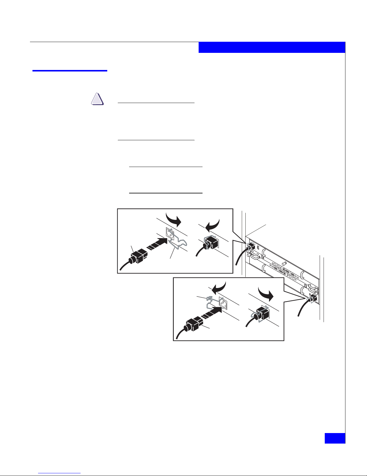
Connecting AC power
CAUTION
!
The disk-array enclosure will power up immediately once you
attach it to an active AC power source. Plan your power
configuration before connecting to a power distribution unit or
standby power supply.
1. Plug an AC line cord into each power/cooling module, as shown
in Figure 2-1.
Make certain you secure the power cord with the retention bails (strain
reliefs) at each connector. The strain reliefs prevent the power cord from
pulling out of the connections.
Figure 2-1 Plugging in the AC line cords
!!
!!
!
EXPPRI
EXP
PRI
#
!
EXP PRI
EXP
PRI
#
A
B
EMC3213
Generic
Plug
Retention Bail
Generic
Plug
Retention
Bail
Page 34

2-6
DAE2P/DAE3P Hardware Reference
Installing a DAE2P/DAE3P
2. For proper cooling and normal operation, make sure all the disk
module slots in each disk enclosure contain either disk or filler
modules.
Do not power up a disk enclosure without at least one LCC installed.
You can configure a driveless disk enclosure within a Fibre Channel bus.
High availability with write-caching requires disks in slots 0-4 in the first
disk enclosure (DPE2, DAE, DAE2P, or DAE3P) connected to a storage
processor (Enclosure Address 0, bus 0).
3. Connect the DAE2P/DAE3P power cords to an appropriate
power source.
a. In most cases, you should connect each power cord to the
closest power distribution unit (pdu) in a cabinet. For
example, connect power/cooling module A to the right pdu,
and power/cooling module B to the pdu on the left (facing the
rear of the cabinet). For high availability, always connect each
power/cooling module to a separate power source.
Page 35

Connecting AC Power
2-7
Installing a DAE2P/DAE3P
Figure 2-2 shows the power cord connections for a typical
CX300- or CX500-Series configuration.
Figure 2-2 Connecting DAE2P power cords (CX300/CX500 storage system)
b. Highly available, write-caching configurations require that
you connect the first disk enclosure in a storage system (EA 0,
bus 0) to a Standby Power Supply (SPS) for enclosure power.
An integrated disk-and-processor enclosure, such as a CX300 or
CX500-series DPE2, is always the first disk enclosure on the first bus
(0,0). You should not connect any DAE in a DPE2 configuration to an
SPS.
!!
!!
!
EXP PRI
EXPPRI
#
!
EXP PRI
EXPPRI
#
A
B
!!
!!
!
EXP PRI
EXPPRI
#
!
EXP PRI
EXPPRI
#
A
B
!!
!!
!
EXP PRI
EXPPRI
#
!
EXP PRI
EXPPRI
#
A
B
SP B
SP A
DAE2P
DAE2P
DAE2P
ON
I
OFF
O
ON
I
OFF
O
ON
I
OFF
O
ON
I
OFF
O
ON
I
OFF
O
ON
I
OFF
O
EMC3207
SPS B SPS A
240 V 240 V
Power/
Cooling
Module B
Power/
Cooling
Module A
Master
Switch
Power
Cord
SPS
+
-
Page 36
2-8
DAE2P/DAE3P Hardware Reference
Installing a DAE2P/DAE3P
If you do connect a DAE2P/DAE3P to an SPS (if, for example,
the DAE2P/DAE3P is the first disk enclosure in a CX700- or
CX3-series configuration), be sure that you maintain
power/bus integrity; always connect power module A to SPS
A, and module B to SPS B.
Figure 2-3 shows the power cord connections for a typical
CX3-80 configuration.
Figure 2-3 Connecting DAE3P power cords (CX3-80 storage system)
ON
I
OFF
O
ON
I
OFF
O
ON
I
OFF
O
ON
I
OFF
O
ON
I
OFF
O
ON
I
OFF
O
ON
I
OFF
O
ON
I
OFF
O
ON
I
OFF
O
ON
I
OFF
O
ON
I
OFF
O
ON
I
OFF
O
!!
!!
!
EXP PRI
EXPPRI
#
!
EXP PRI
EXPPRI
#
A
B
!!
!!
!
EXP PRI
EXPPRI
#
!
EXP PRI
EXPPRI
#
A
B
!!
!!
!
EXP PRI
EXPPRI
#
!
EXP PRI
EXPPRI
#
A
B
!!
!!
!
EXP PRI
EXPPRI
#
!
EXP PRI
EXPPRI
#
A
B
!!
!!
!
EXP PRI
EXPPRI
#
!
EXP PRI
EXPPRI
#
A
B
!!
!!
!
EXP PRI
EXPPRI
#
!
EXP PRI
EXPPRI
#
A
B
!!
!!
!
EXP PRI
EXPPRI
#
!
EXP PRI
EXPPRI
#
A
B
!!
!!
!
EXP PRI
EXPPRI
#
!
EXP PRI
EXPPRI
#
A
B
!
!
!
!
!
!
SPS
+
-
Power source APower source B
EMC3419
Page 37

Connecting AC Power
2-9
Installing a DAE2P/DAE3P
4. Repeat steps 1 through 3 for each disk enclosure in the cabinet, as
necessary.
5. Set any SPS switches, and then the master (or main circuit
breaker) switches, to the on position. The disk enclosures in the
cabinet power up.
The only power switches that control DAE2Ps and DAE3Ps are those on
the SPS and the cabinet master switch or circuit breakers, which are
normally on. As a result, a DAE2P/DAE3P is always active.
When you initially apply AC power to a disk enclosure, the disk
drive modules power up according to their specifications, and
spin up in a staggered sequence. The slot spin-up delays range
from 0 to 84 seconds. (The same delays are used when you insert
a drive module while the system is powered up.)
Page 38

2-10
DAE2P/DAE3P Hardware Reference
Installing a DAE2P/DAE3P
Setting the enclosure address
Before you specify an enclosure address or connect your
DAE2P/DAE3P to a back end bus, make certain the loop (bus) and
EA are in agreement.
Each disk enclosure in a Fibre Channel bus must have a unique
enclosure address (also called an EA, or enclosure ID) that identifies
the enclosure and determines disk module IDs. In many cases, the
factory sets the enclosure address before shipment to coincide with
the rest of the system; you will need to reset the selection if you
installed the enclosure into your rack independently. The enclosure
address ranges from 0 through 7 (valid addresses for CX300 and
CX500 systems are 0, 1, 2, and 3 only). You set the EA with the
enclosure selection button. To set the EA, use a tool such as a pen,
paper clip, or small screwdriver.
The enclosure address is set at installation. Disk module IDs are numbered
left to right (facing the unit) and are contiguous throughout an array:
enclosure 0 contains modules 0-14; enclosure 1 contains modules 15-29;
enclosure 2 includes 30-44, and so on through eight enclosures.
When you set up a new DAE we recommend that you segregate
enclosures by bus speed and type whenever practical. For example,
configure DAE2Ps on separate buses (loops) from DAE2s to achieve
the maximum advantage of their point-to-point fault and data
isolation. You should also keep 2 Gb enclosures (any DAE with 2 Gb
disks) and 4 Gb DAE3P enclosures on separate buses. (A 4 Gb bus
will not recognize 2 Gb devices unless the bus speed is manually reset
to the slower speed). Wherever possible, assign a new DAE with
enclosures of its speed and type to the next logically available
back-end (BE) bus and address, and balance the number of enclosures
on each bus. For example, if your system supports two buses (loops)
and includes only an enclosure 0 on bus 0, you would start a second
bus and add the new DAE as enclosure 0 on bus 1. If the same two-BE
system has three enclosures on bus 0 and two enclosures of the same
speed and type on bus 1, add the new DAE as enclosure 2 on bus 1.
Optimize your system by using every available bus, and spreading
the number of enclosures as evenly as possible across the buses.
Page 39

Setting the enclosure address
2-11
Installing a DAE2P/DAE3P
CAUTION
!
Each drive reads its FC-AL physical address at powerup or when
the drive is reset. To avoid losing data, you must set the enclosure
address when power is on and the enclosure is not part of a back-end
bus; you cannot change the EA while the back end is connected.
1. Set the enclosure address to the desired value, as shown in
Figure 2-4. The address is indicated by the appropriate LED next
to the selection button; each button press increments the value.
You can set the EA on either link control card. The second LCC will
automatically change to the new value.
Figure 2-4 Setting the enclosure address (EA)
!!
!!
!
EXP PRI
EXPPRI
#
!
EXP PRI
EXPPRI
#
A
B
012
3
456
7
012
3
456
7
Bus ID
Enclosure
Address
#
EA Selection
(Press here to
change EA)
EMC3210
Page 40

2-12
DAE2P/DAE3P Hardware Reference
Installing a DAE2P/DAE3P
Connecting the DAE2P/DAE3P to the back end bus
Attach your DAE2P/DAE3P to a back end bus after you have set the
enclosure address.
1. Attach the copper cable from the external device (storage
processor, DAE2, or another DAE2P/DAE3P) to the PRI
connector as shown in Figure 2-5. If you are continuing the bus to
another DAE2P/DAE3P, attach a cable from the EXP connector to
the PRI connector in the next DAE2P/DAE3P.
Use HSSDC-HSSDC2 cables to connect a CX-series DPE2 , DAE2, or SPE;
use HSSDC2-HSSDC2 cables to connect DAE2Ps and DAE3Ps, and use
SFP-HSSDC2 cables to connect to a CX3-series SPE.
CAUTION
!
Make sure to orient the HSSDC2 connectors as shown in Figure 2-5.
The connector thumb clip faces up when connecting to LCC B, and
down when connecting to LCC A. An audible/tangible click
indicates that the cable is completely seated in the LCC connector.
Figure 2-5 Connecting a disk enclosure to another FC device
2. If you are installing multiple disk enclosures, cable them as
shown in Figures 2-6 and
Figure 2-7.
!!
!!
!
EXP PRI
EXPPRI
#
!
EXP
PRI
EXPPRI
#
A
B
EMC3244
To Previous Enclosure
PRI
Connector
PRI
PRI
Thumb Clip Up
To Previous Enclosure
PRI
Connector
PRI
PRI
Thumb Clip Down
Page 41

Connecting the DAE2P/DAE3P to the back end bus
2-13
Installing a DAE2P/DAE3P
The figures in this chapter show configurations with DAE2P/DAE3Ps as
the only disk-array enclosures. Environments with a mix of DAE2 and
DAE2P/DAE3P enclosures follow the same EA, bus balancing, and
cabling conventions whenever possible and practical.
The configuration example in Figure 2-6 shows a CX3-series
Model 40 storage processor enclosure (SPE3) below eight DAE3P
disk-array enclosures. Each of the eight devices supports two
completely redundant loops. Note that the external device
connects to the Primary disk enclosure connectors, and
subsequent enclosures connect in an Expansion-to-Primary chain.
Figure 2-6 Cabling disk enclosures together — two Fibre Channel buses
!!
!!
!
EXP PRI
EXPPRI
#
!
EXP PRI
EXPPRI
#
A
B
!!
!!
!
EXP PRI
EXPPRI
#
!
EXP PRI
EXPPRI
#
A
B
!!
!!
!
EXP PRI
EXPPRI
#
!
EXP PRI
EXPPRI
#
A
B
!!
!!
!
EXP PRI
EXPPRI
#
!
EXP PRI
EXPPRI
#
A
B
!!
!!
!
EXP PRI
EXPPRI
#
!
EXP PRI
EXPPRI
#
A
B
!!
!!
!
EXP PRI
EXPPRI
#
!
EXP PRI
EXPPRI
#
A
B
!!
!!
!
EXP PRI
EXPPRI
#
!
EXP PRI
EXPPRI
#
A
B
!!
!!
!
EXP PRI
EXPPRI
#
!
EXP PRI
EXPPRI
#
A
B
SPS ASPS B
LCC B LCC A
EMC3412
Bus 1
Bus 0
Bus 1
Bus 0
EA0/Bus 0
EA1/Bus 0
EA2/Bus 0
EA3/Bus 0
EA0/Bus 1
EA1/Bus 1
EA2/Bus 1
EA3/Bus 1
Page 42

2-14
DAE2P/DAE3P Hardware Reference
Installing a DAE2P/DAE3P
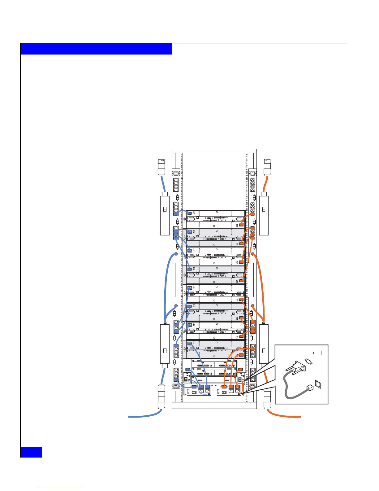
Figure 2-7 shows a more complicated configuration with ten
DAE3Ps and four Fibre Channel buses.
Figure 2-7 Cabling DAE2Ps/DAE3Ps together — four Fibre Channel buses
!!
!!
!
EXP PRI
EXPPRI
#
!
EXP PRI
EXPPRI
#
A
B
!!
!!
!
EXP PRI
EXPPRI
#
!
EXP PRI
EXPPRI
#
A
B
!!
!!
!
EXP PRI
EXPPRI
#
!
EXP PRI
EXPPRI
#
A
B
!!
!!
!
EXP PRI
EXPPRI
#
!
EXP PRI
EXPPRI
#
A
B
!!
!!
!
EXP PRI
EXPPRI
#
!
EXP PRI
EXPPRI
#
A
B
!!
!!
!
EXP PRI
EXPPRI
#
!
EXP PRI
EXPPRI
#
A
B
!!
!!
!
EXP PRI
EXPPRI
#
!
EXP PRI
EXPPRI
#
A
B
!!
!!
!
EXP PRI
EXPPRI
#
!
EXP PRI
EXPPRI
#
A
B
!!
!!
!
EXP
EXP
PRI
PRI
EXP
EXP
PRI
PRI
#
!
EXP
EXP
PRI
PRI
EXP
EXP
PRI
PRI
#
A
B
!!
!!
!
EXP
EXP
PRI
PRI
EXP
EXP
PRI
PRI
#
!
EXP
EXP
PRI
PRI
EXP
EXP
PRI
PRI
#
A
B
!
!
!
!
!
!
SPS ASPS B
LCC B LCC A
EMC3410
Bus 3
Bus 1
Bus 2
Bus 0
Bus 3
Bus 1
Bus 2
Bus 0
EA0/Bus 0
EA1/Bus 0
EA2/Bus 0
EA0/Bus 1
EA1/Bus 1
EA2/Bus 1
EA0/Bus 2
EA1/Bus 2
EA0/Bus 3
EA1/Bus 3
Page 43

Binding disk modules into RAID groups
2-15
Installing a DAE2P/DAE3P
Binding disk modules into RAID groups
After cabling the disk enclosure, use EMC Navisphere® Manager
software to bind the disks into RAID groups. Refer to the EMC
Navisphere Manager Administrator’s Guide and your storage processor
configuration and planning guide for detailed information.
Disk configuration rules and recommendations
The following rules and recommendations apply to all CX-series and
CX3-series systems.
◆ You cannot use any of the disks 000 through 004 (enclosure 0,
bus 0, disks 0-4) as a hot spare in a CX-series or CX3-series
system.
◆ The hardware reserves several gigabytes on each of disks 000
through 004 for the cache vault and internal tables. To conserve
disk space, you should avoid binding any other disk into a RAID
group that includes any of these disks. Any disk you include in a
RAID group with a cache disk 000-004 is bound to match the
lower unreserved capacity, resulting in lost storage of several
gigabytes per disk.
◆ Each disk in the RAID group should have the same capacity. All
disks in a Group are bound to match the smallest capacity disk,
and you could waste disk space. The first five drives (000-004)
should always be the same size.
◆ You cannot mix drive types within a RAID group. ATA
(Advanced Technology Attachment), Fibre Channel, and Serial
ATA (SATA) disk drives cannot share a RAID group.
◆ ATA drives require ATA hot spares. Hot spares for Fibre Channel
and SATA drives can be either type; we recommend SATA spares
for SATA drives and Fibre Channel spares for Fibre Channel
drives whenever possible.
◆ If a storage system uses disks of different capacities and/or
speeds (for example, 146 GB and 73 GB, or 10K and 15K rpm)
within any enclosure, then EMC recommends that you place them
in a logical order, such as the following:
• Place drives with the highest capacity in the first (leftmost)
slots, followed by drives of lower capacities.
Page 44

2-16
DAE2P/DAE3P Hardware Reference
Installing a DAE2P/DAE3P
• Within any specific capacity, place drives of the highest speed
first, followed by drives of lower speed.
◆ You should always use disks of the same speed and capacity in
any RAID group.
◆ Do not use ATA or SATA drives to store boot images of an
operating system. You must boot host operating systems from a
Fibre Channel drive.
Page 45

Servicing a DAE2P/DAE3P
3-1
3
Invisible Body Tag nvisible
This chapter describes how to monitor disk enclosure status, handle
FRUs, and replace or add a Field Replaceable Unit (FRU). Topics are:
◆ Monitoring disk enclosure status ....................................................3-2
◆ Handling FRUs...................................................................................3-6
◆ Replacing or adding a disk module ..............................................3-10
◆ Replacing an LCC module..............................................................3-17
◆ Replacing a power supply/system cooling module...................3-20
For more information about upgrading your DAE2P/DAE3P, contact your
service provider.
Servicing a
DAE2P/DAE3P
Page 46

3-2
DAE2P/DAE3P Hardware Reference
Servicing a DAE2P/DAE3P
Monitoring disk enclosure status
Status lights on the DAE2P/DAE3P and its FRUs indicate error
conditions. These lights are visible outside the disk enclosure. Some
lights are visible from the front, and the others from the back. Figures
Figures 3-1 through 3-4 and Tables Tables 3-1 through 3-3 describe the
status lights.
Figure 3-1 Front disk enclosure and disk module status lights (bezel removed)
Table 3-1 describes the LEDs visible from the front of the
DAE2P/DAE3P.
EMC2166a
Power LED
(Green or Blue)
Fault LED
(Amber)
Fault LED
(Amber)
Disk Activity
LED
(Green)
Page 47

Monitoring disk enclosure status
3-3
Servicing a DAE2P/DAE3P
Table 3-1 Status lights visible from the front of the disk enclosure
Light Quantity Color Meaning
Disk Enclosure Power 1 Green
Blue
Power to enclosure is on; back-end bus running at 2 Gb/s
Power to DAE3P enclosure is on; back-end bus running at 4 Gb/s
Disk Enclosure Fault 1 Amber On when any fault condition exists; if the fault is not obvious from
a disk module light, look at the back of the disk enclosure.
Disk Active 1 per disk module Green Off when the slot is empty or contains a filler module.
Also off when the disk is powered down by command; for
example, the result of a temperature fault.
Flashing (mostly off) when the FC drive is powered up but not
spinning; this is a normal part of the spin
-up sequence, occurring
during the spin-up delay of a slot.
Flashing (at a constant rate) when the FC drive is spinning up or
spinning down normally.
On when the drive has power but is not handling any I/O activity
(the ready state).
Flashing (mostly on) when the drive is spinning and handling I/O
activity.
Disk Fault 1 per disk module Amber On when the disk module is faulty, or as an indication to remove
the drive.
Page 48

3-4
DAE2P/DAE3P Hardware Reference
Servicing a DAE2P/DAE3P
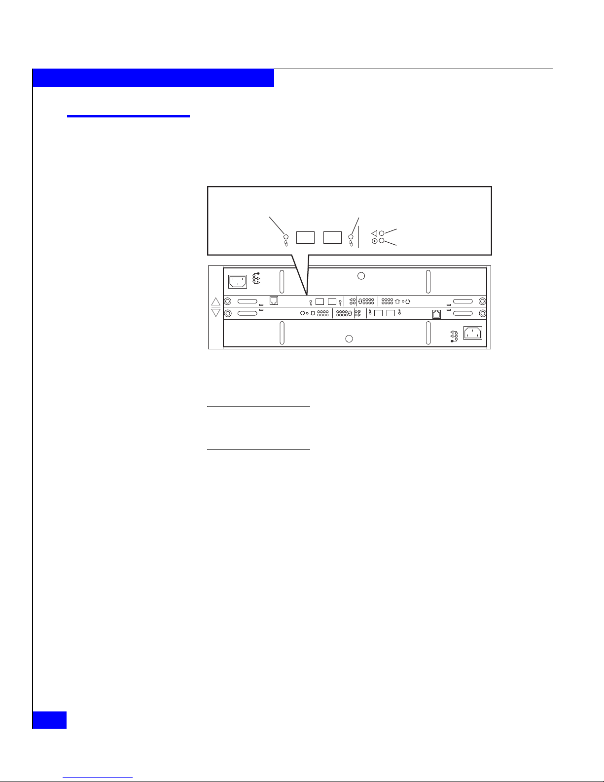
Figure 3-2 shows the enclosure address and bus ID indicators, visible
from the back of the enclosure. In this example, the DAE2P/DAE3P is
enclosure 2 on loop (bus) 1; note that the indicators for LCC A and
LCC B must always match.
Figure 3-2 Enclosure address and bus ID indicators
Table 3-2 describes the ID indicators.
Figure 3-3 shows the status LEDs for the power supply/system
cooling (power/cooling) modules.
!!
!!
!
EXP PRI
EXPPRI
#
!
EXP PRI
EXPPRI
#
A
B
012
3
456
7
012
3
456
7
Loop ID
Enclosure
Address
#
EA
Selection
0
1
2
3
4
5
6
7
0
1
2
3
4
5
6
7
Loop ID
Enclosure
Address
#
EA
Selection
EMC3178
Table 3-2 Enclosure and bus ID indicators
Light Quantity Color Meaning
Enclosure Address 8 Green Displayed number indicates Enclosure Address
bus ID 8 Blue Displayed number indicates bus ID
Blinking bus ID indicates invalid cabling; LCC A and
LCC B are not connected to the same bus or bus
maximum exceeded.
Page 49
Monitoring disk enclosure status
3-5
Servicing a DAE2P/DAE3P
Figure 3-3 Power/cooling module status indicators
Figure 3-4 shows the status LEDs for the link control cards.
Figure 3-4 LCC status LEDs
!!
!!
!
EXP PRI
EXPPRI
#
!
EXP PRI
EXPPRI
#
A
B
!!
Power LED (Green)
Power Fault LED (Amber)
Blower Fault LED (Amber)
EMC3179
!!
Power LED (Green)
Power Fault LED (Amber)
Blower Fault LED (Amber)
!!
!!
!
EXP PRI
EXPPRI
#
!
EXP PRI
EXPPRI
#
A
B
EMC3184
Expansion Link
Active LED (Green or Blue)
Primary Link
Active LED (Green or Blue)
Fault LED (Amber)
Power LED (Green)
!
EXP PRI
EXPPRI
Expansion Link
Active LED (Green or Blue)
Primary Link
Active LED (Green or Blue)
Fault LED (Amber)
Power LED (Green)
!
EXP PRI
EXPPRI
Page 50

3-6
DAE2P/DAE3P Hardware Reference
Servicing a DAE2P/DAE3P
Table 3-3 describes the status LEDs visible from the rear of the disk
enclosure.
If the disk enclosure Fault light is on, examine the other status lights
to determine which FRU(s) is faulty. If a fault light on a FRU remains
on, you should replace that FRU as soon as possible.
When a redundant FRU fails, high availability will be compromised until you
replace the faulty FRU.
Handling FRUs
This section describes the precautions that you must take and the
general procedures you must follow when removing, installing, and
storing FRUs.
Power issues and
FRUs
The DAE2P/DAE3P is designed to always be powered up and hot
repairable. Its front bezel should be attached and each of its
Table 3-3 Status lights visible from the rear of the disk enclosure
Light Quantity Color Meaning
LCC Power 1 per LCC Green On when the LCC is powered up.
LCC Fault 1 per LCC Amber On when either the LCC or a Fibre Channel connection is faulty.
Also on during Power On Self Test (POST).
Primary Link Active 1 per LCC Green On when Primary connection is active; back-end bus running at 2Gb
Blue On when Primary connection is active; back-end bus running at 4Gb
Expansion Link Active 1 per LCC Green On when Expansion connection is active; back-end bus running at 2Gb
Blue On when Expansion connection is active; back-end bus running at 4Gb
Power Supply Active 1 per supply Green On when the power supply is operating.
Power Supply Fault* 1 per supply Amber On when the power supply is faulty or is not receiving AC line voltage.
Flashing when either a multiple blower or ambient overtemperature
condition has shut off dc power to the system.
Blower Fault* 1 per cooling module Amber On when a single blower in the power supply is faulty.
* The DAE2P/DAE3P will continue running with a single power supply and three of its four blowers. Removing a power/cooling module constitutes a
multiple blower fault condition, and will power down the enclosure unless you replace a blower within two minutes.
Page 51

Handling FRUs
3-7
Servicing a DAE2P/DAE3P
compartments should contain a FRU or filler panel to ensure EMI
compliance and proper air flow over the FRUs.
While the disk enclosure is powered up, you can service or replace
any FRU, although removing an active LCC will affect operating
system access to the disks it controls. You should not remove a faulty
FRU until you have a replacement available.
Since you can replace or add any FRU without sliding the disk
enclosure out of the cabinet, you do not have to use cabinet anti-tip
devices when you upgrade or service a DAE2P.
If you need to power down a DAE2P/DAE3P, simply unplug the
unit. You do not need to shut down main AC lines to the disk
enclosure unless you need to power down all the cabinet contents
connected to that line.
Avoiding
Electrostatic
Discharge (ESD)
damage
When you replace or install FRUs, you can inadvertently damage the
sensitive electronic circuits in the equipment by simply touching
them. Electrostatic charge that has accumulated on your body
discharges through the circuits. If the air in the work area is very dry,
running a humidifier in the work area will help decrease the risk of
ESD damage. You must follow the procedures below to prevent
damage to the equipment.
Read and understand the following instructions:
◆ Provide enough room to work on the equipment. Clear the work
site of any unnecessary materials or materials that naturally build
up electrostatic charge, such as foam packaging, foam cups,
cellophane wrappers, and similar items.
◆ Do not remove replacement or upgrade FRUs from their antistatic
packaging until you are ready to install them.
◆ Gather together the ESD kit and all other materials you will need
before you service a disk enclosure. Once servicing begins, you
should avoid moving away from the work site; otherwise, you
may build up an electrostatic charge.
◆ An ESD wristband is supplied with your disk enclosure. To use it,
attach the clip of the ESD wristband (strap) to any bare
(unpainted) metal on the disk enclosure; then put the wristband
around your wrist with the metal button against your skin.
Page 52

3-8
DAE2P/DAE3P Hardware Reference
Servicing a DAE2P/DAE3P
◆ Use the ESD kit when handling any FRU. If an emergency arises
and the ESD kit is not available, follow the procedures in the
Emergency Procedures (Without an ESD Kit) section.
Emergency
procedures (without
an ESD kit)
In an emergency when an ESD kit is not available, use the following
procedures to reduce the possibility of an electrostatic discharge by
ensuring that your body and the subassembly are at the same
electrostatic potential.
These procedures are not a substitute for the use of an ESD kit.
Follow them only in the event of an emergency.
◆ Before touching any FRU, touch a bare (unpainted) metal surface
of the cabinet or enclosure.
◆ Before removing any FRU from its antistatic bag, place one hand
firmly on a bare metal surface of the enclosure, and at the same
time, pick up the FRU while it is still sealed in the antistatic bag.
Once you have done this, do not move around the room or touch
other furnishings, personnel, or surfaces until you have installed
the FRU.
◆ When you remove a FRU from the antistatic bag, avoid touching
any electronic components and circuits on it.
◆ If you must move around the room or touch other surfaces before
installing a FRU, first place the FRU back in the antistatic bag.
When you are ready again to install the FRU, repeat these
procedures.
Precautions when
removing, installing,
or storing FRUs
Use the precautions listed below when you remove, handle, or store
FRUs:
◆ Do not remove a faulty FRU until you have a replacement
available.
◆ Handle a FRU only when using an ESD wristband. Attach the clip
of the ESD wristband to the ESD bracket or bare metal on the
enclosure, and put the wristband around your wrist with the
metal button against your skin.
◆ Handle FRUs gently. A sudden jar, drop, or vibration can
permanently damage a FRU and may not be immediately
evident. Never place a FRU on a hard surface such as an
unpadded cart, floor, or desktop, or stacked on top of another
FRU.
Page 53

Handling FRUs
3-9
Servicing a DAE2P/DAE3P
◆ Never use excessive force to remove or install a FRU.
◆ Store a FRU in the antistatic bag and specially designed shipping
container in which you received it. Use that container if you need
to return the FRU for repair.
◆ Store FRUs within the temperature and humidity limits specified
in Appendix A.
◆ Place the cables where no one can step on them or roll equipment
over them.
Page 54
3-10
DAE2P/DAE3P Hardware Reference
Servicing a DAE2P/DAE3P
Replacing or adding a disk module
CAUTION
!
Disk modules are extremely sensitive electronic components.
Always handle a disk module gently, and observe the following
guidelines:
◆ Follow the instructions in the preceding section “Avoiding
Electrostatic Discharge (ESD) damage” on page 3-7.
◆ Do not mix Fibre Channel or SATA components in the same
enclosure. Refer to Figure 3-5 for a visual comparison of disk
carriers (note that SATA drives include a "SATA" designation on
the module label).
Figure 3-5 Disk module comparison
CL3583
Fibre Channel
2- and 4-Gb
Fibre Channel
2-Gb only
SATA
2- and 4-Gb
ATA
(Not supported
)
Page 55

Replacing or adding a disk module
3-11
Servicing a DAE2P/DAE3P
◆ Always wear a properly attached ESD wristband when
removing or replacing a disk module.
◆ Disk modules are sensitive to the extreme temperatures
sometimes encountered during shipping. We recommend that
you leave new disk modules in their shipping material and
expose the package to ambient temperature for at least four
hours before attempting to use the new modules in your
system.
◆ When removing a disk module, pull the module part way out of
the slot, then wait 30 seconds for the drive to spin down before
removing it.
◆ When installing multiple disks in a powered up system, wait at
least 6 seconds before sliding the next disk into position.
◆ Place modules on a soft, antistatic surface, such as an
industry-standard antistatic foam pad or the container used to
ship the module. Never place a disk module directly on a hard
surface.
◆ Never hit modules, stack modules, or allow them to tip over or
fall.
◆ Avoid touching any exposed electronic components and circuits
on the disk module.
◆ Before adding more disks to your configuration planning guide,
which contains guidelines for creating RAID groups with disks
of varying sizes and speeds.
◆ Do not remove a faulty disk module until you have a
replacement module (with the same part number) or a filler
module available. The part number (PN005xxxxxx) appears on
the top or bottom of the module. A replacement disk module
should have the same format (bytes per sector) and the same
capacity (size and speed) as the module it is replacing.
You must remove the disk enclosure’s front bezel to gain access to the
disk modules. The bezel is required for EMI compliance when the
enclosure is powered up. Remove it only to replace or add a disk
module.
Page 56

3-12
DAE2P/DAE3P Hardware Reference
Servicing a DAE2P/DAE3P
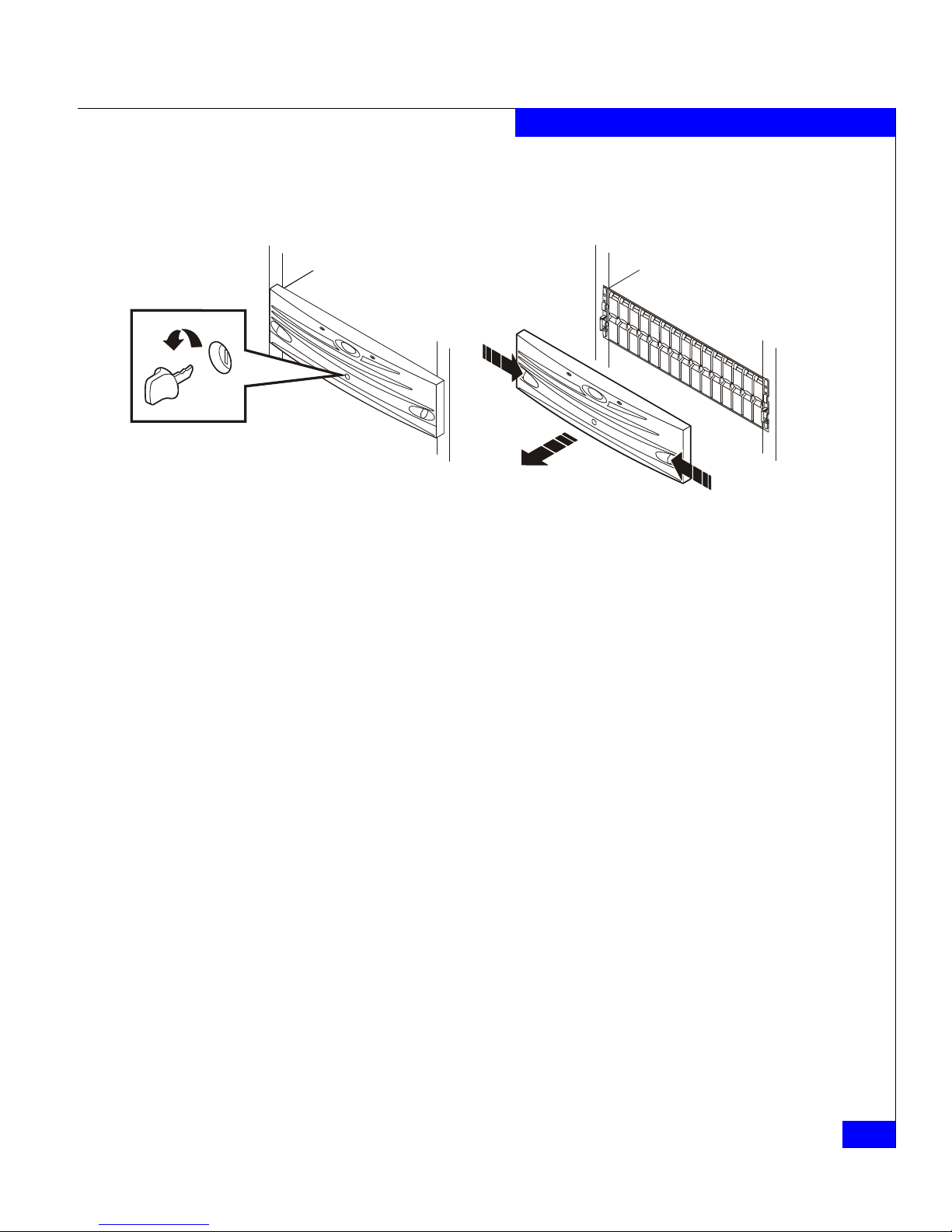
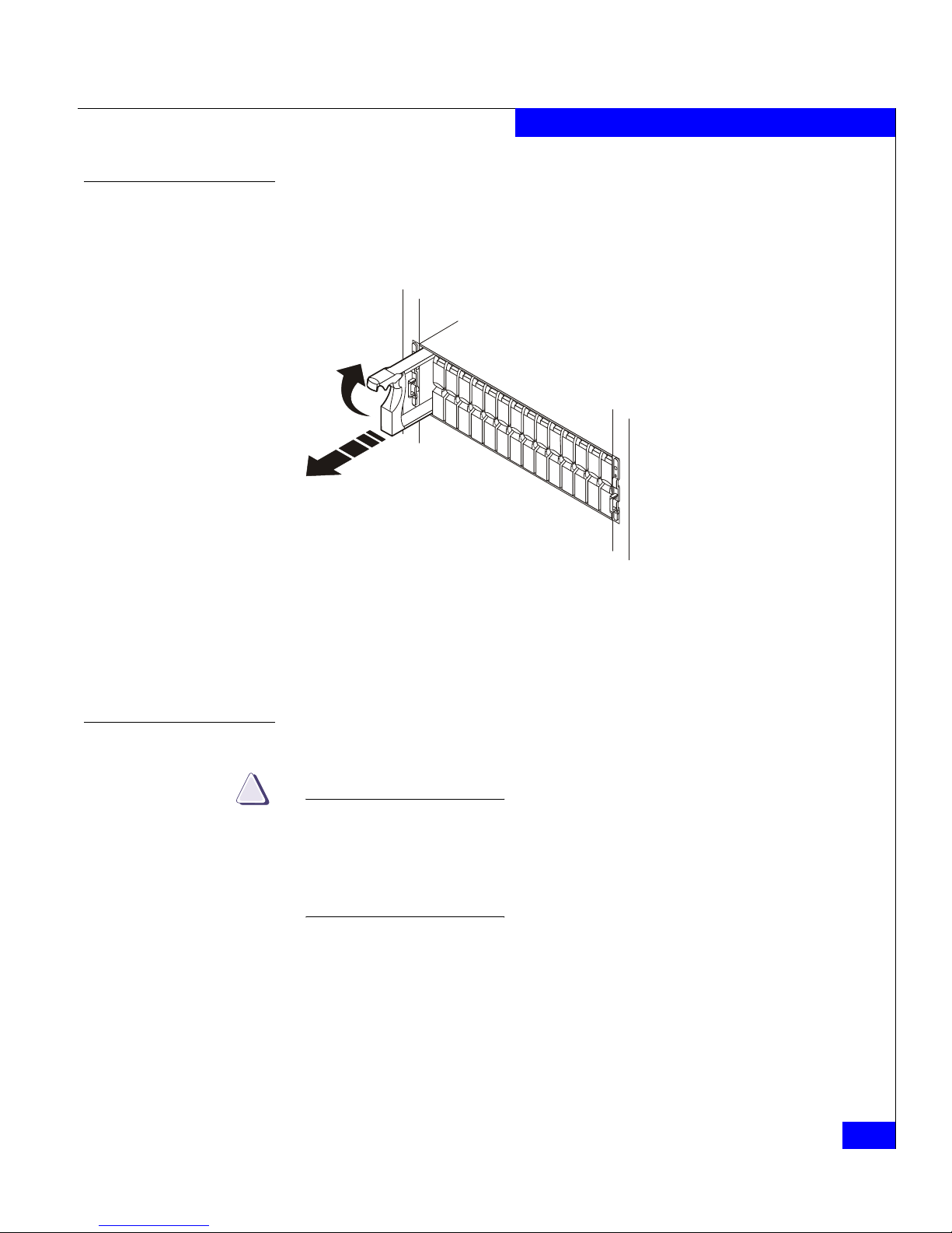
Unlocking and removing the front bezel
Follow these steps to remove the front bezel and gain access to the
disk modules. Refer to Figure 3-6.
1. Insert the key that shipped with your enclosure into the bezel
lock, and turn it to release the lock.
2. Press the two latch buttons on the bezel surface toward each other
to release the bezel from the cabinet.
3. Pull the bezel off the cabinet and put it on a clean, static-free
surface.
Figure 3-6 Unlocking and removing the front bezel
If you are adding a new disk module, continue to the disk filler
module removal procedure that follows. If you are replacing a faulty
disk module, proceed to the disk module removal procedure.
EMC2173
Page 57
Replacing or adding a disk module
3-13
Servicing a DAE2P/DAE3P
Removing a disk filler module
Locate the slot where you want to install the disk module, and
remove the filler module, as shown in Figure 3-7.
Figure 3-7 Removing a disk filler module
Skip to the disk installation procedure (page 3-14) to install the
add-on disk in the slot you just emptied.
Removing a disk module
CAUTION
!
If a disk module has been bound into a LUN, do not move it to
another slot unless you do not care about the data on the LUN. Each
module contains LUN-identifying information written when it was
bound. Moving it to another slot can make information on the
original LUN inaccessible.
Generally, you should not remove a disk module unless its amber
fault light is on. See Ta ble 3-1.
1. Attach an ESD wristband to your wrist and the enclosure (see the
precautions on page 3-7).
EMC2210
Page 58

3-14
DAE2P/DAE3P Hardware Reference
Servicing a DAE2P/DAE3P
2. If the active light is on steadily, pull the latch, and slowly pull the
module about 1 in (3 cm) from its slot. Wait 30 seconds for the
disk to stop spinning. Then remove the module and place it on a
padded, static-free surface.
If the active light is off or mostly off you do not need to wait for
the disk to stop spinning. Pull the latch and slowly pull the
module from its slot, as shown in Figure 3-8. Place it on a padded,
static-free surface.
Figure 3-8 Removing a disk module
Continue to the next section to install the replacement disk module.
Installing a disk or filler module
Always replace a disk drive with another of the same type/model; do not
mix Fibre Channel and SATA components in an enclosure. Refer to Figure 3-5
on page 3-10 for a visual comparison of disk carriers.
An enclosure running at 4 Gb/s will recognize only 4 Gb disks (with a 2/4
mark on the front label). A DAE2P will support 4 Gb disks at 2 Gb/s.
1. Make sure an ESD wristband is attached to your wrist and the
enclosure (see the precautions on page 3-7).
2. Align the module with the guides in the slot.
EMC2174
Page 59

Replacing or adding a disk module
3-15
Servicing a DAE2P/DAE3P
3. Refer to Figure 3-9 as you insert the new disk module.
a. With the disk module latch fully open, gently push the module
into the slot.
b. The disk module latch will begin to rotate downward when its
tabs meet the enclosure chassis.
c. Push the handle down to engage the latch. After the latch is
engaged, push firmly on the bottom of the module to verify
that the disk is properly seated.
Figure 3-9 Installing a disk or filler module
The disk module’s Active light flashes to reflect the disk’s spin-up
sequence.
If you are installing multiple disk modules in a system that is powered
up, wait at least 6 seconds before sliding the next module into position.
4. Remove and store the ESD wristband and continue to the next
section to install the front bezel.
EMC3140
Tabs
A
B
C
Page 60

3-16
DAE2P/DAE3P Hardware Reference
Servicing a DAE2P/DAE3P
Installing and locking the front bezel
Refer to Figure 3-10 as you do the following:
1. Align the bezel with the disk enclosure.
2. Gently push the bezel into place on the cabinet until it latches.
3. Secure the bezel by turning the key in the lock.
Figure 3-10 Installing and locking the front bezel
EMC2222
Page 61

Replacing an LCC module
3-17
Servicing a DAE2P/DAE3P
Replacing an LCC module
CAUTION
!
Handle an LCC gently and use an ESD wristband. Do not remove a
faulty LCC until you have a replacement module available.
LCC modules for DAE2P and DAE3P enclosures are not interchangeable.
Make sure you have the correct replacement part before removing the LCC.
A DAE2P or DAE3P must have at least one LCC installed while it is powered
up. Do not remove both LCCs while the disk enclosure is powered up.
Removing an LCC
1. Gently press the connector latches to release them as you remove
the copper cables connected to the LCC, as shown in Figure 3-11.
Note where the cable(s) connect to the LCC; you will need to reconnect
them to the replacement LCC.
Figure 3-11 Removing a copper cable from an LCC
2. Turn the captive screws counterclockwise to release the module,
and then remove the LCC from its slot, as shown in Figure 3-12.
!!
!!
!
EXP
PRI
EXPPRI
#
!
EXP PRI
EXPPRI
#
A
B
EMC3212
PRI
Connector
PRI
PRI
Page 62

3-18
DAE2P/DAE3P Hardware Reference
Servicing a DAE2P/DAE3P
Figure 3-12 Removing an LCC
Continue to the next section to install the replacement LCC.
Installing an LCC
1. Gently insert the LCC as shown in Figure 3-13. Be sure the module
is completely seated in the enclosure midplane.
Figure 3-13 Installing an LCC
!!
!!
!
EXP PRI
EXPPRI
#
A
B
EMC3227
Captive Screw
Captive Screw
!
EXP PRI
EXPPRI
#
!!
!!
!
EXP
PRI
EXPPRI
#
A
B
EMC3181
Captive Screw
Captive Screw
!
EXP PRI
EXPPRI
#
Page 63

Replacing an LCC module
3-19
Servicing a DAE2P/DAE3P
The LCC Power light turns on.
2. Secure the module with the captive screws.
3. Reattach the copper cables to the same connector from which you
removed them, as shown in Figure 3-14.
Figure 3-14 Reconnecting a copper cable to an LCC
4. Remove and store the ESD wristband.
!!
!!
!
EXP PRI
EXPPRI
#
!
EXP PRI
EXPPRI
#
A
B
EMC3180
To Previous Enclosure
PRI
Connector
PRI
PRI
Page 64

3-20
DAE2P/DAE3P Hardware Reference
Servicing a DAE2P/DAE3P
Replacing a power supply/system cooling module
CAUTION
!
Handle a power supply/system cooling (power/cooling) module
gently and use an ESD wristband. Do not remove a power/cooling
module until you have a replacement module available.
Access to the disks in your enclosure will time out and the disks
will spin down two minutes after a power/cooling module is
removed from the enclosure. While the system can continue
operating on a single power supply, the loss of a module’s two
blowers will cause a time-out unless you replace the module within
two minutes.
When replacing a power/cooling module, make certain the green
LED on one module has been steadily on for at least 5 seconds
before removing power from the second module.
Follow these steps to replace a power/cooling module.
1. Unplug the AC line cord as shown in Figure 3-15.
Figure 3-15 Unplugging the AC power cord
2. Turn the captive screw counterclockwise to release the module,
and then remove the power/cooling module as shown in
Figure 3-16.
!!
!!
!
EXPPRI
EXP
PRI
#
!
EXP PRI
EXP
PRI
#
A
B
EMCrempwr
Retention Bail
Retention
Bail
Page 65
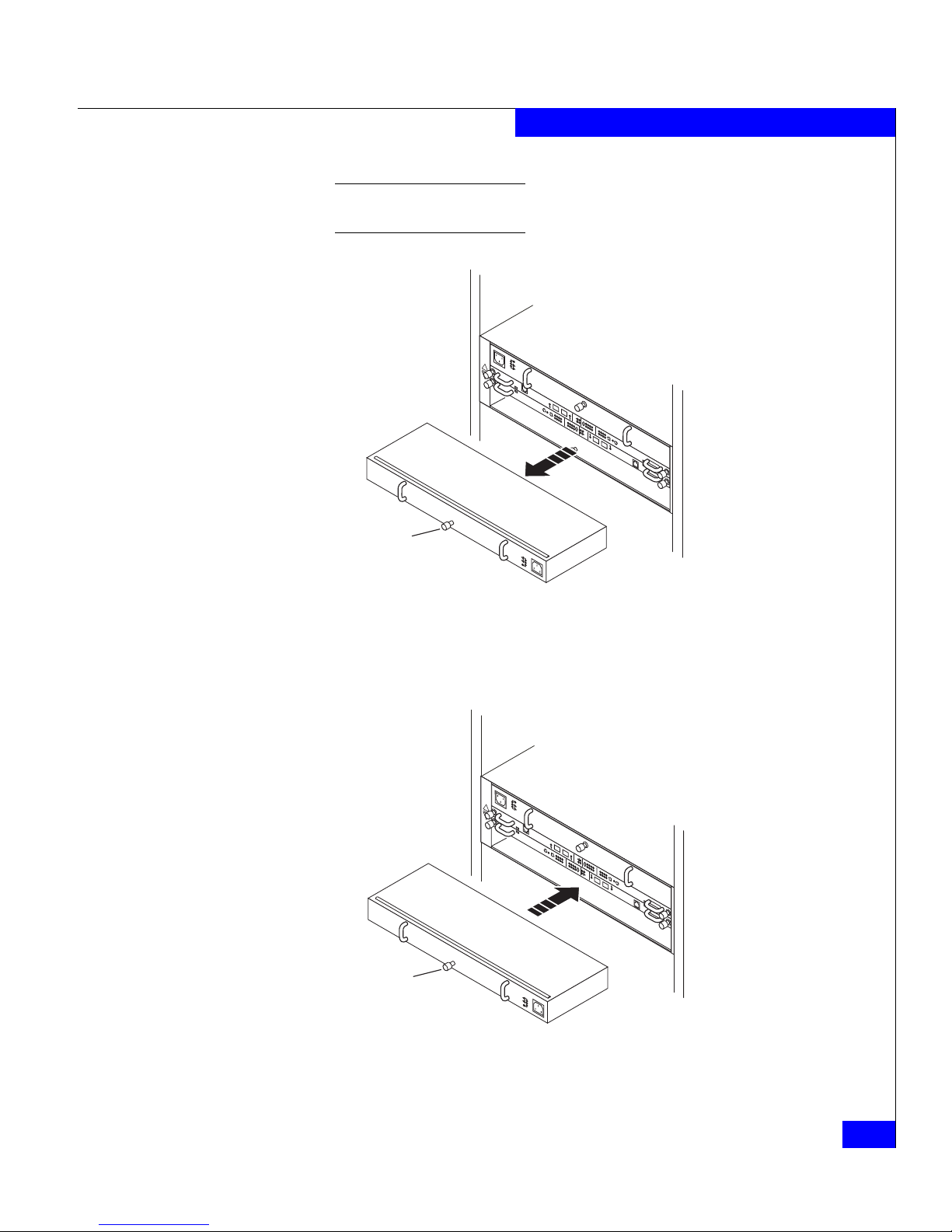
Replacing a power supply/system cooling module
3-21
Servicing a DAE2P/DAE3P
To protect a running system from overheating, the enclosure will time
out unless you replace the power/cooling module within two minutes.
Figure 3-16 Removing a power/cooling module
3. Gently insert the new power/cooling module into the enclosure,
as shown in Figure 3-17. Be sure the module is completely seated.
Figure 3-17 Installing a power/cooling module
4. Secure the module with the captive screw.
!!
!
EXP PRI
EXPPRI
#
!
EXP PRI
EXPPRI
#
A
B
EMC3228
!!
Captive Screw
!!
!
EXP PRI
EXPPRI
#
!
EXP PRI
EXPPRI
#
A
B
EMC3182
!!
Captive Screw
Page 66

3-22
DAE2P/DAE3P Hardware Reference
Servicing a DAE2P/DAE3P
5. Plug the AC power cord into the new supply as shown in
Figure 3-18.
Figure 3-18 Plugging in the power cord
Make certain you secure the power cord with the retention bails at each
connector. The bails prevent the power cord from pulling out of the
connections.
!!
!!
!
EXP PRI
EXPPRI
#
!
EXP PRI
EXP
PRI
#
A
B
EMC3213
Generic
Plug
Retention Bail
Generic
Plug
Retention
Bail
Page 67

Technical specifications
A-1
A
Invisible Body Tag
Body Tag
This appendix describes the disk-array enclosure technical
specifications, operating limits, and shipping and storage
requirements. Major topics are:
◆ Enclosure specifications...................................................................A-2
◆ Operating limits ................................................................................A-5
Technical specifications
Page 68
A-2 DAE2P/DAE3P Hardware Reference
Technical specifications
Enclosure specifications
Technical enclosure specifications include power requirements, size,
drive, interface, and standards information.
AC power
requirements
The input current, power (VA), and dissipation per DAE2P/DAE3P
are based on the requirements that a maximum enclosure
configuration places on the power supplies and cooling system to
provide internal regulated power. Typical values will be less,
depending on the number and manufacturer of disk modules. These
values represent either
◆ the values for a single power supply line cord, or
◆ the sum of values shared by the line cords of two power supplies
in the same DAE2P/DAE3P, with the division between the line
cords and supplies at the current sharing ratio (approximately
50% each).
A failure of one of the two power supplies in the enclosure results in
the remaining supply and cord supporting the full load. You must
use a rackmount cabinet with AC power distribution, and have main
branch AC distribution that can handle these values for each disk
enclosure in the cabinet.
* Ratings assume a fully configured DAE2P/DAE3P that includes two power supplies,
two LCCs, and 15 disk drives.
Table A-1 DAE2P/DAE3P AC power specifications
Requirement Description *
AC line voltage 100 to 240 V AC +
10%, single phase, 47 to 63 Hz
AC line current 4.4 A at 100 V ac, 2.2 A at 200 V ac
Power consumption 440 VA(425 W) max (fully configured)*
Power factor 0.98 min at full load, low voltage
Heat dissipation 1.53 x10
6
J/hr (1,450 BTU/hr) max
In-rush current 50 A max for 1/2 line cycle, per power supply at 240 V ac
25 A max for 1/2 line cycle, per power supply at 120 V ac
Startup surge current 15 A pk (10.6 A rms) max for 100 ms, at any line voltage
AC protection 10 A fuse in each power supply, both phases
AC receptacle type IEC320-C14 appliance coupler, per power supply
Ride-through time 30 ms min
Current sharing 60% max, 40% min, between power supplies
Page 69
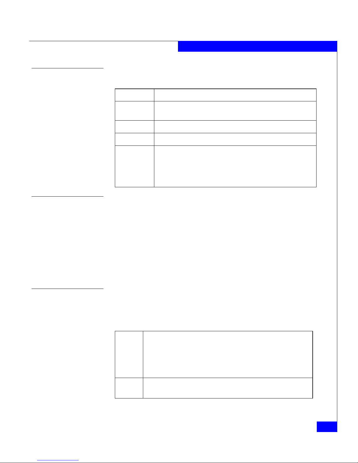
Enclosure specifications
A-3
Technical specifications
Size and weight
Drive type
The DAE2P/DAE3P uses 3.5-inch (8.75 cm) by 1.0-inch (2.54 cm) disk
drives. Standard, Fibre Channel drives are 12-volt, and support the
Fibre Channel interface. SATA drives (DAE3P only) are 12- and 5-volt
and support the SATA 3 Gb/s interface; a paddle card on the drive
converts the assembly to 12-volt, 4 Gb/s Fibre Channel operation.
Each drive slot provides an average maximum of 16 W drive module
power.
Refer to the EMC Storage Systems CX-Series Disk and FLARE OE Matrix
for a list of supported drives.
LCC FC-AL interface
Connectors are shielded HSSDC2 (High Speed Serial Data
Connector).
Copper cabling
HSSDC2
Requirement Measurement
Height 133.35 mm (5.25 in)
3 NEMA units including mounting hardware
Width 450 mm (17.72 in)
Depth 355.6 mm (14 in)
Weight 30.91 kg (68 lbs) maximum configuration;
1.1 kg (2.4 lbs) per FC disk module x15 max = 16.4 kg (36 lbs);
0.7 kg (1.5 lbs) per link control card x 2 =1.4 kg (3 lbs)
2.5 kg (5.5 lbs) per power supply x 2 = 5.0 kg (11 lbs)
8.2 kg (18 lbs) chassis and midplane
Type: Shielded, 150 Ω differential, shield bonded to plug connector shell (360°)
FC-PI-2 Standard, Revision 13 or higher for HSSDC2
SFF-8470 150 specification for SFP transceiver
HSSDC2 -HSSDC2 for DAE2P/DAE3P-DAE2P/DAE3P connection;
HSSDC2-SFP for DAE2P/DAE3P to CX3-series back-end
HSSDC-HSSDC2 for connection to CX-series DPE, SPE, or DAE2
Length: 2 meters (6.6 feet);5 meters (16.5 feet) and 8 meters (26.4 feet)
Maximum 5-meter support for SFP-HSSDC2 connection
Page 70

A-4 DAE2P/DAE3P Hardware Reference
Technical specifications
Standards certification and compliance
Rackmount disk enclosures are tested and certified for compliance
with the international environmental and safety specifications listed
below and marked to indicate such compliance and certification as
required.
Fibre Channel related standards
In some cases, the DAE2P/DAE3P uses functions from later revisions of specifications.
Standard Description
Fibre Channel Physical and signaling interface, FC-PI-2, draft Rev. 7 or higher
Fibre Channel Arbitrated Loop (FC-AL), Revision 4.5
Fibre Channel Private Loop Direct Attach (PLDA), Revision 2.1
Page 71
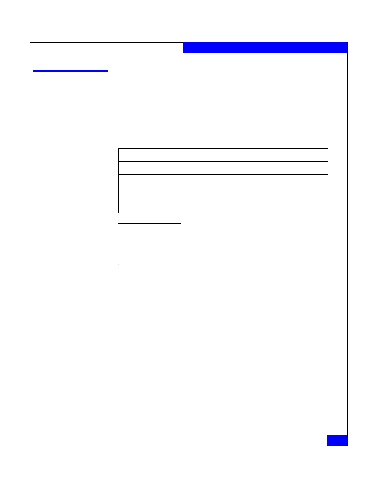
Operating limits
A-5
Technical specifications
Operating limits
The ambient temperature specification is measured at the front bezel
inlet. The site must have air conditioning of the correct size and
placement to maintain the specified ambient temperature range. The
air conditioning must be able to handle the heat dissipation
requirements of the disk enclosures.
The operating limits for temperature and humidity must not be exceeded
inside the closed cabinet in which the DAE2Ps are mounted. Mounting
equipment in a cabinet directly above or below a DAE2P/DAE3P does not
restrict air flow to the disk enclosure, because air flows through the enclosure
from front to back. Cabinet doors must not impede the front-to-back air flow.
Environmental recovery
If the system exceeds maximum ambient temperature by
approximately 10°C/18°F, the storage processors will begin an
orderly shutdown that saves cached data, shuts off the SPs, and — in
a DPE2 enclosure — powers down the disks. LCCs in each
DAE2P/DAE3P will power down their disks but remain powered on.
If the system detects that the temperature has dropped to an
acceptable level, it restores power to the storage processors (which
power up any disks in their enclosure), and the LCCs restore power
to their disk drives.
Requirement Description
Ambient temperature 10
o
C to 40oC (50oF to 104oF)
Temperature gradient 10
o
C/hr (18oF/hr)
Relative humidity 20% to 80% noncondensing
Elevation 2438 m (8,000 ft) at 40oC, 3077 m (10,000 ft) at 37oC
Page 72
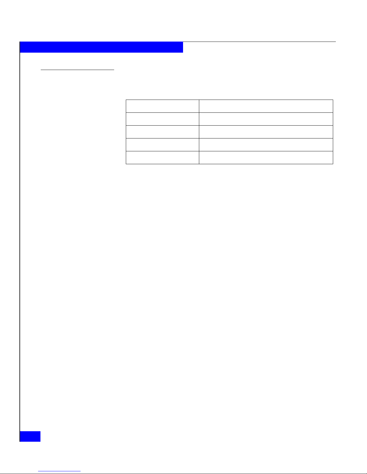
A-6 DAE2P/DAE3P Hardware Reference
Technical specifications
Shipping and storage requirements
Requirement Description
Ambient temperature -40
o
C to 65oC (-40oF to 149oF)
Temperature gradient 25
o
C/hr (45oF/hr)
Relative humidity 10% to 90% noncondensing
Elevation 7625 m (25,000 ft)
Page 73

DAE2P/DAE3P Hardware Reference
i-1
A
ac power cord
attaching to power supply 3-22
removing from power supply 3-20
Active light
LCC 3-6
power supply 3-6
adding
disk module 3-10
ATA disks
configuration rules 2-15
B
binding RAID groups 2-15
C
cabinet, installing DAE2P in 2-3
cables
reattaching to LCC 3-19
removing from LCC 3-17
requirements 2-2
cabling
precautions 3-9
requirements 2-2
certification
DPE2 iv
chassis see enclosure
check light
DAE2P components 3-2
LCC 3-6
power supply 3-6
comments xii
compliance
DPE2 iv
components 1-3
Cooling Check light 3-6
customer support xii
D
DAE2P (2-gigabit point-to-point disk-array
enclosure)
disk module
description 1-9
disk drive 1-10
drive carrier 1-11
EA indicator 3-4
front bezel
description 1-6
operating limits A-5
power supply 1-11
powering down 3-7, 3-20
powering up 3-22
rear 1-5
requirements
operating A-5
technical specifications A-2
disk configuration rules 2-15
disk drive
description 1-10
specifications A-3
disk module
adding 3-10
binding into RAID groups 2-15
description 1-9
disk drive 1-10
Index
Page 74

DAE2P/DAE3P Hardware Reference
i-2
Index
drive carrier 1-11
drive specifications A-3
disks
configuration rules 2-15
documentation, related x
drive carrier description 1-11
E
EA (enclosure address)
indicator 3-4
requirements 2-10
setting 2-11
EA indicator 3-4
electromagnetic interference (EMI)
shield 1-6
standards certification/compliance iv
electrostatic discharge (ESD)
avoiding 3-7
enclosure
description 1-3
EA indicator 3-4
midplane description 1-6
rear, description 1-5
Enclosure Address (EA)
requirements 2-10
setting 2-11
Enclosure ID, see Enclosure Address
environmental recovery A-5
F
FC-AL (Fibre Channel Arbitrated Loop)
cabling A-3
requirements 2-2
connector A-3
interface specifications A-3
physical address 2-10
Fibre Channel
related standards A-4
front bezel
description 1-6
unlocking and removing 3-12
FRUs (field-replaceable units)
defined 1-3
disk module
description 1-9
removing 3-13
handling 3-6
LCC
description 1-8
replacing 3-17
power issues 3-6
power supply
description 1-11
replacing 3-20
storing 3-6
G
grounding xiii
H
help 1-xii
hot spare
restrictions 2-15
I
indicators, ID 3-4
installation requirements 2-2
installing
DAE2P in cabinet 2-3
disk filler modules 3-14
L
LCC (link control card)
cabling A-3
requirements 2-2
description 1-8
FC-AL connector A-3
reattaching cables to 3-19
removing copper cables 3-17
replacing 3-17
status light
Active 3-6
status lights 1-9
lights, DAE2P status 3-2
M
midplane 1-6
monitoring 3-2
Page 75

i-3
DAE2P/DAE3P Hardware Reference
Index
O
overtemperature recovery A-5
P
power
issues and FRUs 3-6
overview 2-2
power supply
attaching ac power cord 3-22
description 1-11
removing
ac power cord 3-20
replacing 3-20
status lights
Active 3-6
Check 3-6
Cooling Check 3-6
turning off 3-20
turning on 3-22
powering down DAE2P 3-7, 3-20
powering up DAE2P 3-22
R
RAID groups 2-15
rear
description 1-5
recovery
environmental A-5
removing
disk module 3-13
replacing
LCC 3-17
power supply 3-20
requirements
cabling 2-2
S
service xii
shipping requirements A-6
site requirements 2-2
specifications, DAE2P A-2
standards
DPE2 iv
status
monitoring DAE2P 3-2
status lights, DAE2P 3-2
T
technical specifications, DAE2P A-2
technical support xii
turning off power supply 3-7, 3-20
turning on power supply 3-22
Page 76

DAE2P/DAE3P Hardware Reference
i-4
Index
 Loading...