

EMC CX700, CLARiiON CX300, CLARiiON CX500, CLARiiON CX500i, CLARiiON CX700 Planning Manual

EMC CLARiiON
CX300, CX500, CX500i, and CX700 Storage Systems
CONFIGURATION PLANNING GUIDE
P/N 300-001-273
REV A04
EMC Corporation
Corporate Headquarters
Hopkinton, MA 01748 -9103
1
-508 -435 -1000
www.EMC.com
:

Copyright © 2003, 2004 EMC Corporation. All rights reserved.
Published November, 2004
EMC believes the information in this publication is accurate as of its publication date. The
information is subject to change without notice.
THE INFORMATION IN THIS PUBLICATION IS PROVIDED "AS IS." EMC CORPORATION
MAKES NO REPRESENTATIONS OR WARRANTIES OF ANY KIND WITH RESPECT TO THE
INFORMATION IN THIS PUBLICATION, AND SPECIFICALLY DISCLAIMS IMPLIED
WARRANTIES OF MERCHANTABILITY OR FITNESS FOR A PARTICULAR PURPOSE.
Use, copying, and distribution of any EMC software described in this publication requires an
applicable software license.
Trademark Information
EMC2, EMC, CLARiiON, Navisphere, PowerPath, and Symmetrix are registered trademarks and Access Logix, FLARE, MirrorView, Powerlink,
SAN Copy, SnapView, and TimeFinder are trademarks of EMC Corporation.
All other trademarks used herein are the property of their respective owners.
ii
EMC CLARiiON CX300, CX500, CX500i, and CX700 Storage Systems Configuration Planning Guide

Contents
Preface............................................................................................................................. ix
Chapter 1 About CX300, CX500, CX500i, and CX700 Storage
Systems
Introducing CX300, CX500, CX500i, and CX700 Storage
Systems.............................................................................................. 1-2
Fibre Channel .................................................................................. 1-4
Fibre Channel Storage Components...................................... 1-5
Storage Component (Storage System Enclosures)............... 1-8
iSCSI ................................................................................................ 1-10
iSCSI Storage Components.................................................... 1-10
Initiator Components............................................................. 1-11
LAN Components................................................................... 1-11
Target Components................................................................ 1-12
Types of Storage-System Installations ........................................ 1-13
About Switched Shared Storage and SANs (Storage Area
Networks) ....................................................................................... 1-14
Storage Groups........................................................................ 1-15
Chapter 2 RAID Types and Trade-offs
EMC CLARiiON CX300, CX500, CX500i, and CX700 Storage Systems Configuration Planning Guide
Introducing RAID............................................................................ 2-2
Disk Striping.............................................................................. 2-2
Mirroring.................................................................................... 2-2
RAID Groups and LUNs ......................................................... 2-3
RAID Types....................................................................................... 2-4
RAID 5 Group (Individual Access Array) ............................ 2-4
RAID 3 Group (Parallel Access Array).................................. 2-5
iii

Contents
RAID 1 Mirrored Pair .............................................................. 2-7
RAID 1/0 Group (Mirrored RAID 0 Group)........................ 2-8
RAID 0 Group (Nonredundant Array) ............................... 2-10
Individual Disk Unit.............................................................. 2-10
Hot Spare................................................................................. 2-11
RAID Benefits and Trade-offs...................................................... 2-13
Performance ............................................................................ 2-14
Storage Flexibility................................................................... 2-15
Data Availability and Disk Space Usage............................. 2-16
Guidelines for RAID Groups....................................................... 2-18
Sample Applications for RAID Types......................................... 2-20
Chapter 3 Storage-System Management
Management Ports .......................................................................... 3-2
Navisphere Management Suites.................................................... 3-4
Access Logix Software............................................................. 3-4
Navisphere Manager................................................................ 3-5
Navisphere Host Agent and CLI............................................ 3-5
Navisphere Analyzer............................................................... 3-5
Navisphere Integrator.............................................................. 3-5
Using Navisphere Software ........................................................... 3-6
Navisphere Management Worksheet.................................... 3-8
Chapter 4 Data Replication and
Data Mobility Software
Data Replication and Data Mobility Software Overview.......... 4-2
What Is SnapView?.......................................................................... 4-3
Clones Overview and Example.............................................. 4-3
Snapshots Overview and Example........................................ 4-5
Clone and Snapshot Trade-offs.............................................. 4-7
SnapView Worksheets............................................................. 4-8
What Is MirrorView?..................................................................... 4-11
MirrorView Example ............................................................. 4-11
MirrorView Features and Benefits....................................... 4-13
MirrorView Planning Worksheet......................................... 4-15
What Is MirrorView/A? ............................................................... 4-17
MirrorView/A Example........................................................ 4-18
MirrorView/A Features and Benefits ................................. 4-19
MirrorView/A Planning Worksheets ................................. 4-22
What Is EMC SAN Copy? ............................................................ 4-24
iv
EMC CLARiiON CX300, CX500, CX500i, and CX700 Storage Systems Configuration Planning Guide

SAN Copy Example............................................................... 4-26
SAN Copy Features and Benefits ........................................ 4-27
Implementing SAN Copy Over Extended Distances ....... 4-28
SAN Copy Planning Worksheet .......................................... 4-30
Chapter 5 Planning File Systems and LUNs
Multiple Paths to LUNs.................................................................. 5-2
Disk IDs ............................................................................................ 5-2
Sample Shared Switched Installation........................................... 5-2
Sample Unshared Direct Installation ........................................... 5-5
Planning Applications, LUNs, and Storage Groups.................. 5-6
Application and LUN Planning............................................. 5-7
LUN and Storage Group Planning Worksheet.................... 5-9
LUN Details Worksheet ........................................................ 5-14
Chapter 6 Storage-System Hardware
Storage-System Installation Types................................................ 6-2
Hardware for CX300, CX500, CX500i, and CX700 Storage
Systems ............................................................................................. 6-3
Storage Hardware.................................................................... 6-3
Storage Processor (SP)............................................................. 6-5
Disks........................................................................................... 6-7
Planning Your Hardware Components ....................................... 6-8
Components for Storage Systems.......................................... 6-8
Hardware Dimensions and Requirements.................................. 6-9
Cabinets for Enclosures................................................................ 6-10
Fibre Channel Data Cable and Configuration Guidelines...... 6-11
Fibre Channel Front-End Hardware Planning Worksheets .... 6-12
Contents
Chapter 7 iSCSI Configuration
Index ............................................................................................................................... i-1
EMC CLARiiON CX300, CX500, CX500i, and CX700 Storage Systems Configuration Planning Guide
Storage System iSCSI Data Port Worksheet ............................... 7-2
iSCSI Initiator Port Worksheet ..................................................... 7-3
v

Contents
vi
EMC CLARiiON CX300, CX500, CX500i, and CX700 Storage Systems Configuration Planning Guide

Figures
1-1 CX700 Storage System .................................................................................. 1-3
1-2 Nodes - Initiator and Target ........................................................................ 1-4
1-3 Switch and Point-to-Point Connections ..................................................... 1-6
1-4 A Switch Zone ................................................................................................ 1-7
1-5 Typical 16-Port Switch, Back View ............................................................. 1-7
1-6 CX700 Storage Processor Enclosure (SPE) ................................................. 1-8
1-7 Nodes - Initiator and Target ...................................................................... 1-10
1-8 Switch and Point-to-Point Connections ................................................... 1-11
1-9 Types of Storage-System Installation ....................................................... 1-13
1-10 Components of a SAN ................................................................................ 1-14
1-11 Sample Shared Storage Configuration ..................................................... 1-16
1-12 Data Access Control with Shared Storage ............................................... 1-17
2-1 Multiple LUNs in a RAID Group ................................................................ 2-3
2-2 RAID 5 Group ................................................................................................ 2-5
2-3 RAID 3 Group ................................................................................................ 2-6
2-4 RAID 1 Mirrored Pair ................................................................................... 2-8
2-5 RAID 1/0 Group ........................................................................................... 2-9
2-6 How a Hot Spare Works ............................................................................ 2-12
2-7 Disk Space Usage in the RAID Configuration ........................................ 2-17
3-1 Storage Domains on the Internet ................................................................ 3-7
4-1 Clones Example ............................................................................................. 4-4
4-2 Snapshot Example ......................................................................................... 4-6
4-3 Sample MirrorView Configuration .......................................................... 4-12
4-4 Sample Remote Mirror Configuration ..................................................... 4-19
4-5 Sample SAN Copy Sessions Between Storage Systems ......................... 4-26
4-6 Sample SAN Copy Over IP Configuration .............................................. 4-29
5-1 Sample Shared Switched Storage Configuration ...................................... 5-3
5-2 Unshared Direct Storage System ................................................................ 5-5
6-1 Types of Fibre Channel Storage-System Installations ............................. 6-2
6-2 CX700 Storage System .................................................................................. 6-4
EMC CLARiiON CX300, CX500, CX500i, and CX700 Storage Systems Configuration Planning Guide
vii

Contents
6-3 Shared Storage Systems ............................................................................... 6-5
6-4 Disks and Their IDs ...................................................................................... 6-7
viii
EMC CLARiiON CX300, CX500, CX500i, and CX700 Storage Systems Configuration Planning Guide

Preface
As part of an effort to improve and enhance the performance and capabilities
of its product line, EMC from time to time releases revisions of its hardware
and software. Therefore, some functions described in this guide may not be
supported by all revisions of the software or hardware currently in use. For
the most up-to-date information on product features, refer to your product
release notes.
If a product does not function properly or does not function as described in
this guide, please contact your EMC representative.
About this Manual This planning guide introduces EMC
®
CLARiiON® CX300, CX500,
CX500i, and CX700 disk-array storage systems and offers useful
background information and worksheets to help you plan.
Audience Read this guide
◆ if you are considering purchase of a CX300, CX500, CX500i, or
CX700 disk-array storage system and want to understand its
features; or
◆ before you plan the installation of a storage system.
You should be familiar with the host servers that will use the storage
systems and with the operating systems on the servers. After reading
this guide, you will be able to
◆ Determine the best storage-system components for your
installation
◆ Determine your site requirements
◆ Configure storage systems correctly
EMC CLARiiON CX300, CX500, CX500i, and CX700 Storage Systems Configuration Planning Guide
ix

Preface
Organization This manual is organized as follows:
Chapter 1 Provides background information about Fibre Channel
and iSCSI features and explains the major types of
storage.
Chapter 2 Describes the RAID Groups and the different ways they
store data.
Chapter 3 Explains storage management software.
Chapter 4 Describes the optional EMC storage-system based
applications for replicating data or copying data within
or between CLARiiON storage systems:
◆ EMC SnapView™ software for replicating data with
a storage system using snapshots or clones.
◆ EMC MirrorView™ and EMC
MirrorView/Asynchronous remote mirroring
software for replicating data between storage
systems.
Conventions Used in
This Guide
!
◆ EMC SAN Copy ™ software for creating clones and
snapshots within a storage system.
Chapter 5 Helps you plan your storage-system file systems and
LUNs.
Chapter 6 Describes the hardware components of storage systems.
Chapter 7 Explains how to configure CX500i iSCSI storage systems.
EMC uses the following conventions for notes and cautions.
A note presents information that is important, but not hazard-related.
CAUTION
A caution contains information essential to avoid data loss or
damage to the system or equipment. The caution may apply to
hardware or software.
x
EMC CLARiiON CX300, CX500, CX500i, and CX700 Storage Systems Configuration Planning Guide

Preface
Finding Current
Information
The most up-to-date version of this manual is posted on the EMC
Powerlink
™
website. We recommend that you download the latest
version before you plan the installation of a storage system.
To access EMC Powerlink, use the following link:
http://powerlink.emc.com
After you log in, select Support > Document Library.
Where to Get Help For questions about technical support, call your local sales office or
service provider.
If you have a valid EMC service contract, contact EMC Customer
Service at:
United States: (800) 782-4362 (SVC-4EMC)
Canada: (800) 543-4782 (543-4SVC)
Worldwide: (508) 497-7901
Follow the voice menu prompts to open a service call and select the
applicable product support.
Sales and Customer
Service Contacts
For the list of EMC sales locations, please access the EMC home page
at:
http://www.EMC.com/contact/
For additional information on the EMC products and services
available to customers and partners, refer to the EMC Powerlink
website at:
http://powerlink.EMC.com
Your Comments Your suggestions will help us continue to improve the accuracy,
organization, and overall quality of the user publications. Please send
a message to techpub_comments@EMC.com with your opinions of
this guide.
EMC CLARiiON CX300, CX500, CX500i, and CX700 Storage Systems Configuration Planning Guide
xi

Preface
xii
EMC CLARiiON CX300, CX500, CX500i, and CX700 Storage Systems Configuration Planning Guide

Invisible Body Tag
1
About CX300, CX500,
CX500i, and CX700
Storage Systems
This chapter introduces CLARiiON® CX300, CX500, CX500i, and
CX700 disk-array storage systems and storage area networks (SANs).
Major sections are
◆ Introducing CX300, CX500, CX500i, and CX700
Storage Systems..................................................................................1-2
◆ Fibre Channel......................................................................................1-4
◆ iSCSI...................................................................................................1-10
◆ Types of Storage-System Installations...........................................1-13
◆ About Switched Shared Storage and SANs (Storage Area
Networks)..........................................................................................1-14
About CX300, CX500, CX500i, and CX700 Storage Systems
1-1

About CX300, CX500, CX500i, and CX700 Storage Systems
Introducing CX300, CX500, CX500i, and CX700 Storage Systems
EMC CLARiiON CX300, CX500, CX500i, and CX700 disk-array
storage systems provide terabytes of disk storage capacity, high
transfer rates, flexible configurations, and highly available data at
low cost. Their hardware RAID features are provided by two storage
processors (SPs).
Table 1-1 outlines each storage system enclosure and disk capacities.
Table 1-1 Storage System Enclosures and Disk Capacities
Maximum Number of 2-Gigabit
Storage System Enclosure Type
Number of Disks per
Storage System Enclosure
Disk-Array Enclosures (DAE2s)a and
Disks
CX300 2-Gbit Disk Processor
Enclosure (DPE2)
CX500 & CX500i 2-Gbit Disk Processor
Enclosure (DPE2)
CX700 Storage Processor
Enclosure (SPE)
a. Each DAE2 enclosure has slots for 15 disks.
Two types of DAE2s are available:
◆ a standard DAE2 version with high-performance Fibre Channel
disks
◆ a DAE2-ATA version with economical ATA (Advanced
Technology Attachment) disks.
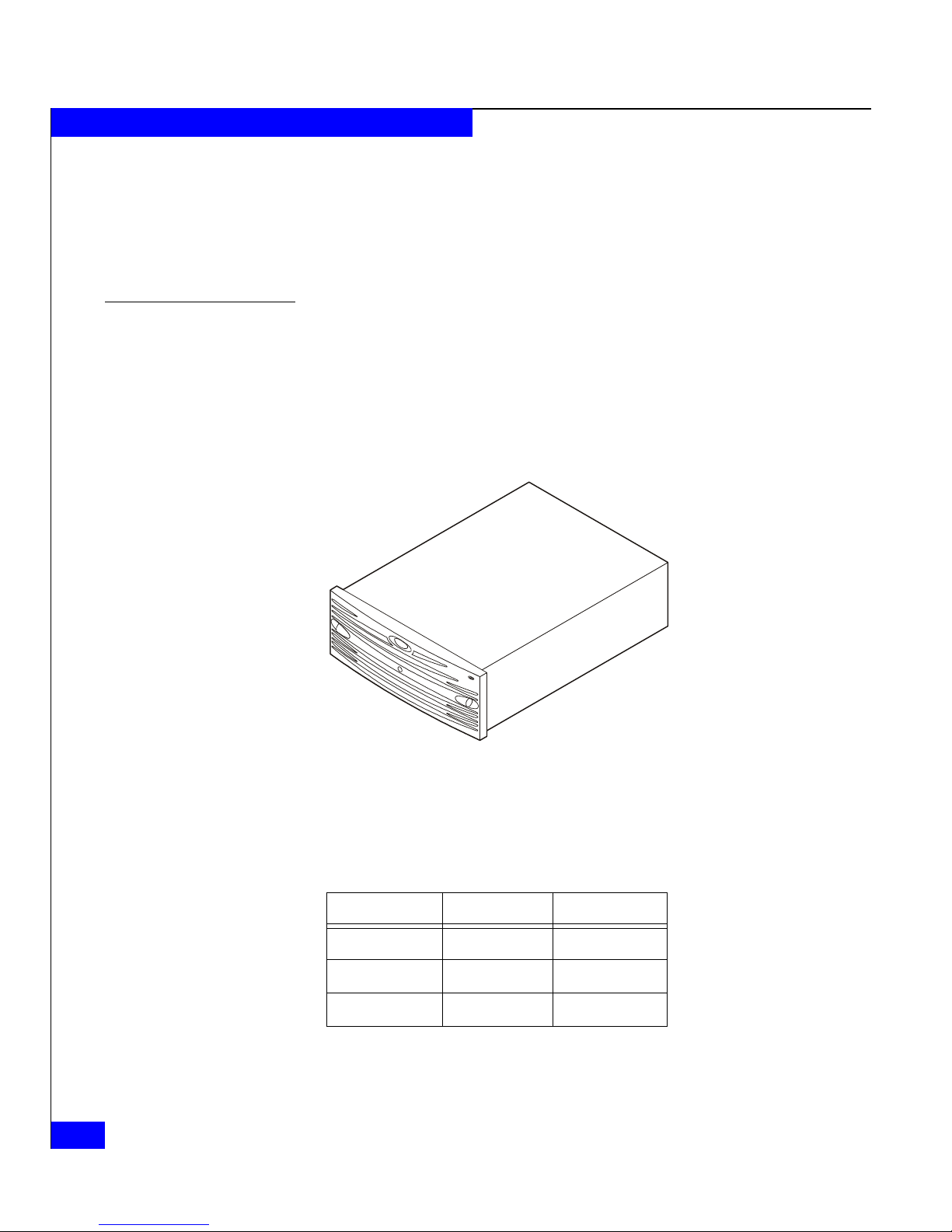
Figure 1-1 shows a typical CX700 storage system.
15 Fibre Channel disks 3 separate DAE2s for a total of 60 disks
15 Fibre Channel disks 7 separate DAE2s for a total of 120 disks
An SPE does not include disks,
and requires at least one 2-Gbit
Disk-Array Enclosure (DAE2)
with Fibre Channel disks.
16 separate DAE2s for a total of 240 disks
1-2
EMC CLARiiON CX300, CX500, CX500i, and CX700 Storage Systems Configuration Planning Guide
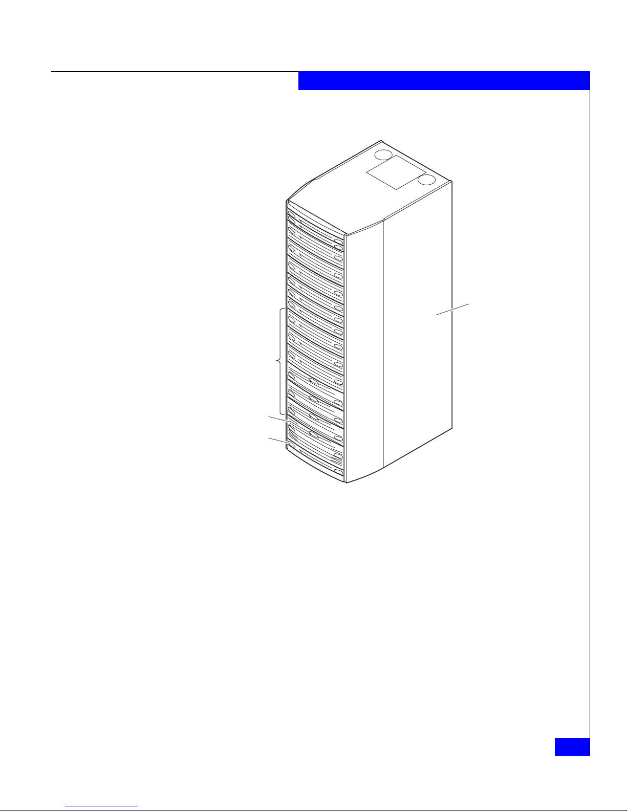
DAE2s
About CX300, CX500, CX500i, and CX700 Storage Systems
Rackmount
Cabinet
SPE
SPS
Figure 1-1 CX700 Storage System
A storage-system package includes storage management software,
Fibre Channel interconnect hardware, and one or more storage
systems. The host bus adapter driver hardware and software are
available from outside vendors.
EMC2737
Introducing CX300, CX500, CX500i, and CX700 Storage Systems
1-3
About CX300, CX500, CX500i, and CX700 Storage Systems
Fibre Channel
Fibre Channel is a high-performance serial protocol that allows
transmission of both network and I/O channel data. It is a low level
protocol, independent of data types, and supports such formats as
SCSI and IP.
The Fibre Channel standard supports several physical topologies,
including switch fabric point-to-point and arbitrated loop (FC-AL).
The Fibre Channel storage systems described in this manual use
switch fabric and FC-AL topologies.
A switch fabric is a set of point-to-point connections between nodes;
each connection is made through one or more Fibre Channel
switches. Each node may have its own unique address, but the path
between nodes is governed by a switch. The nodes are connected by
optical cable.
A Fibre Channel arbitrated loop is a circuit consisting of nodes. Each
node has a unique address, called a Fibre Channel arbitrated loop
address. The nodes connect with optical cables. An optical cable can
transmit data over great distances for connections that span entire
enterprises and can support remote disaster recovery systems.
Each connected device in a switched fabric or arbitrated loop is a
server adapter (initiator) or a target (storage system). The switches
are not considered nodes.
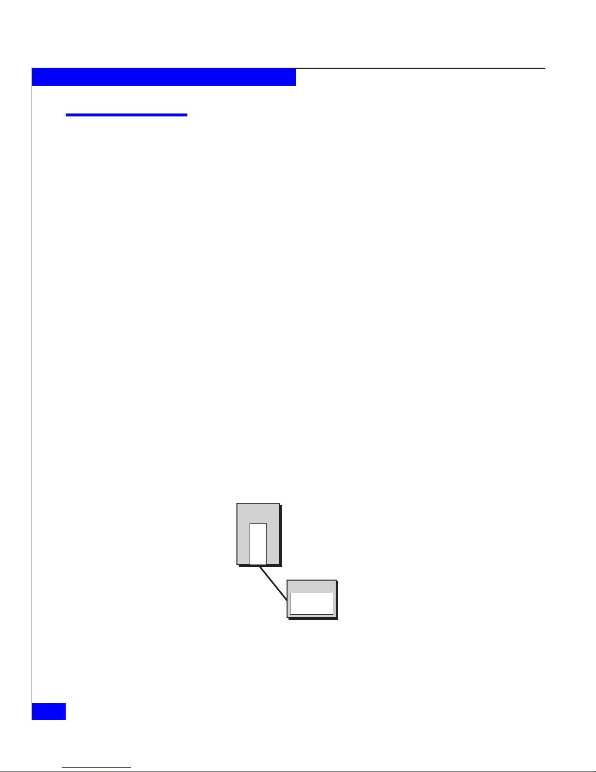
Figure 1-2 shows a node and initiator.
Server Adapter (Initiator)
Node
Adapter
Storage System (Target)
Connection
Figure 1-2 Nodes - Initiator and Target
Node
EMC1802
1-4
EMC CLARiiON CX300, CX500, CX500i, and CX700 Storage Systems Configuration Planning Guide
About CX300, CX500, CX500i, and CX700 Storage Systems
Fibre Channel Storage Components
A Fibre Channel storage system has three main components:
◆ Server component (host bus adapter driver with adapter and
software)
◆ Interconnect components (cables based on Fibre Channel
standards, and switches)
◆ Storage component (storage system with storage processors,
power supply, cooling hardware, and disks)
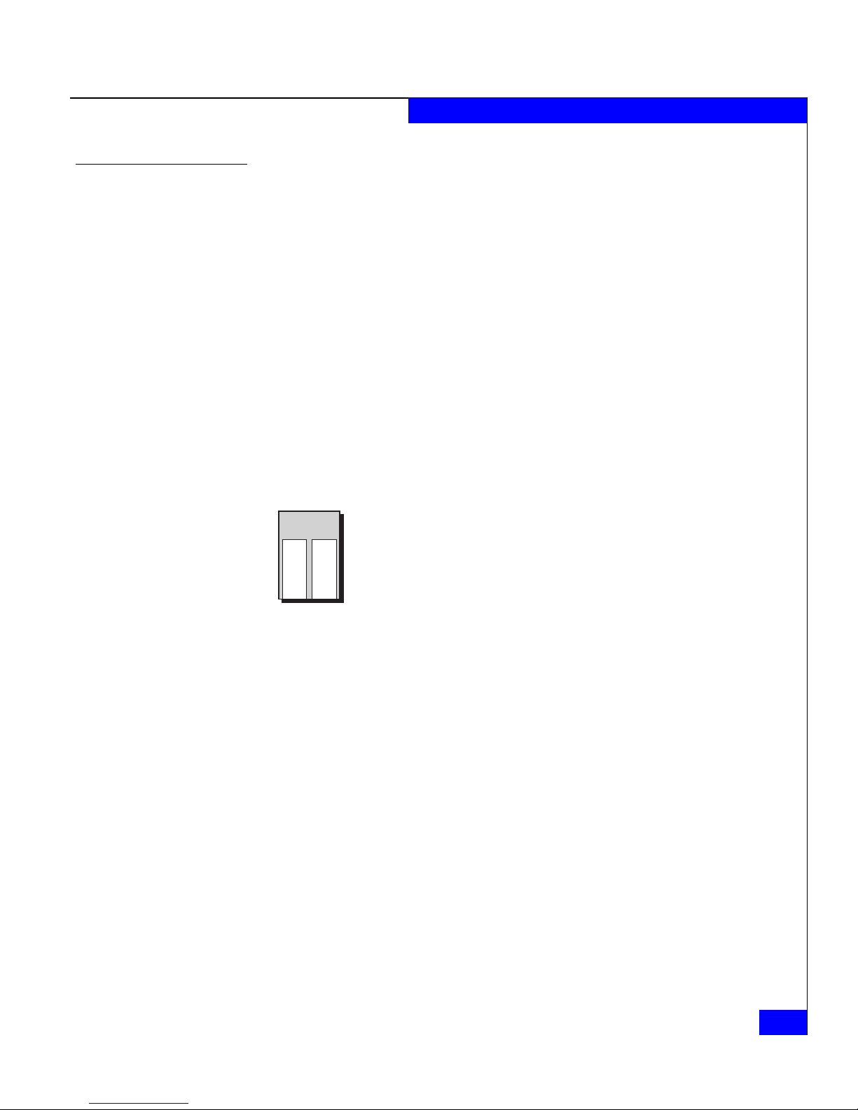
Server Component (Host Bus Adapter and Driver)
The host bus adapter is a printed-circuit board that slides into an I/O
slot in the server’s cabinet. It transfers data between server memory
and one or more disk-array storage systems over Fibre Channel — as
controlled by the support software (adapter driver).
Server
Adapter
Adapter
EMC1803
Interconnect Components
The interconnect components include the optical cables between
components and any Fibre Channel switches.
The maximum length of optical cable between a CX300, CX500, and
CX700 storage system and a server or switch ranges from 150 to 500
meters (165 to 550 yards), depending on the type of cable and
operating speed. With extenders, connections between servers,
switches, and other devices can span up to 60 kilometers (36 miles) or
more. This ability to span great distances ia a major advantage of
optical cable.
Details on cable lengths and rules appear later, in Chapter 6.
Fibre Channel Switches
A Fibre Channel switch, which is required for switched shared
storage (a storage area network, SAN), connects all the nodes cabled
to it using a fabric topology. A switch adds serviceability and
scalability to any installation; it allows online insertion and removal
of any device on the fabric and maintains integrity if any connected
Fibre Channel
1-5
About CX300, CX500, CX500i, and CX700 Storage Systems
device stops participating. A switch also provides
server-to-storage-system access control and point-to-point
connections.
Server
A
d
a
p
t
e
r
SP
Storage System
Figure 1-3 Switch and Point-to-Point Connections
SP
Server
A
d
a
p
t
e
r
Server
A
d
a
p
t
e
r
SP
Storage System
SP
You can cascade switches (connect one switch port to another switch)
for additional port connections.
Switch Zoning
Switch zoning lets an administrator define paths between connected
nodes based on the node’s unique World Wide Name. Each zone
includes a server adapter and/or one or more SPs. EMC recommends
single-initiator zoning, which limits each zone to a single HBA port
(initiator). The current connection limits are outlined in Table 1-2.
EMC1805
Table 1-2 Connection Limits
1-6
EMC CLARiiON CX300, CX500, CX500i, and CX700 Storage Systems Configuration Planning Guide
Maximum HBA Ports
Storage System
CX300 32 128
CX500 64 256
CX700 64 512
per SP
Maximum HBA Ports
per Storage System
About CX300, CX500, CX500i, and CX700 Storage Systems
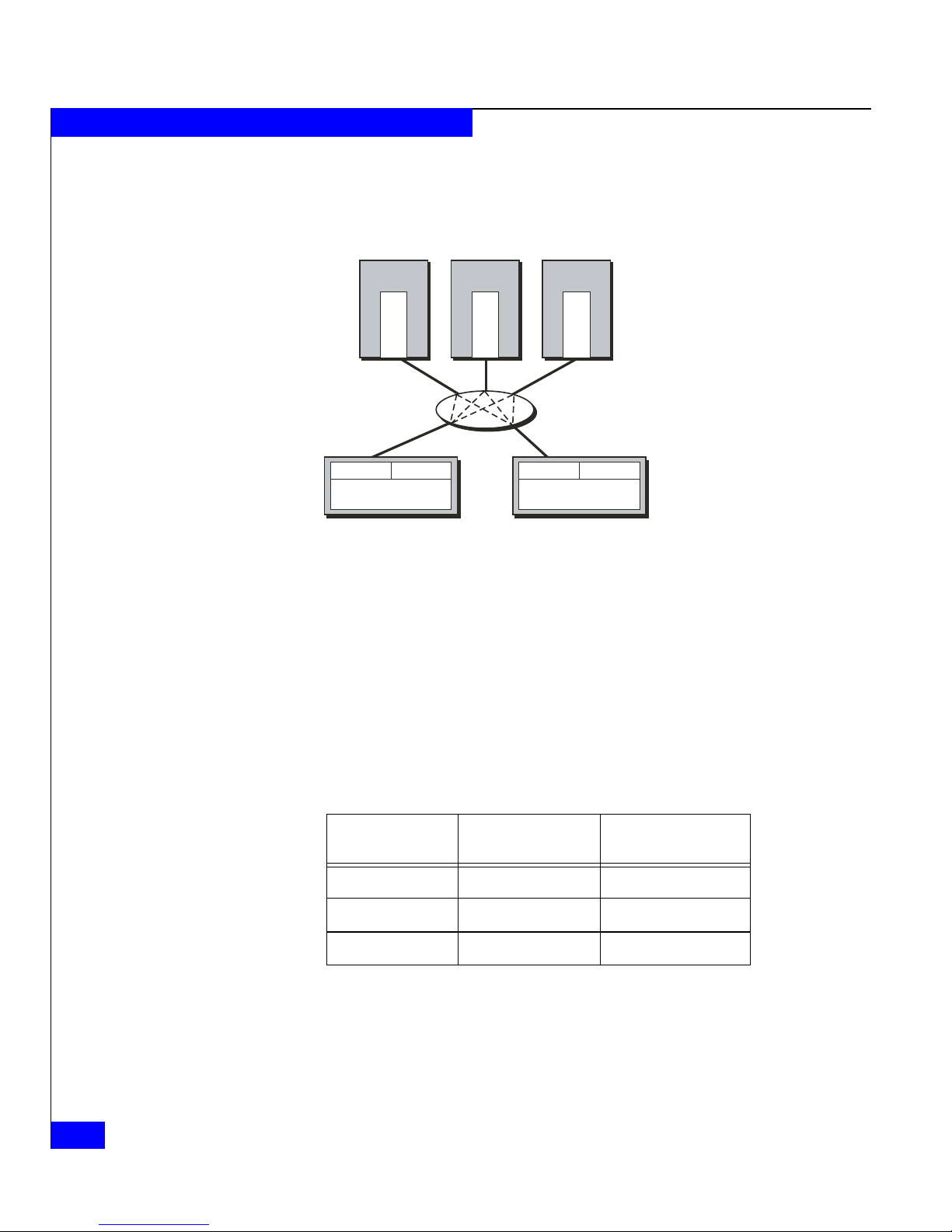
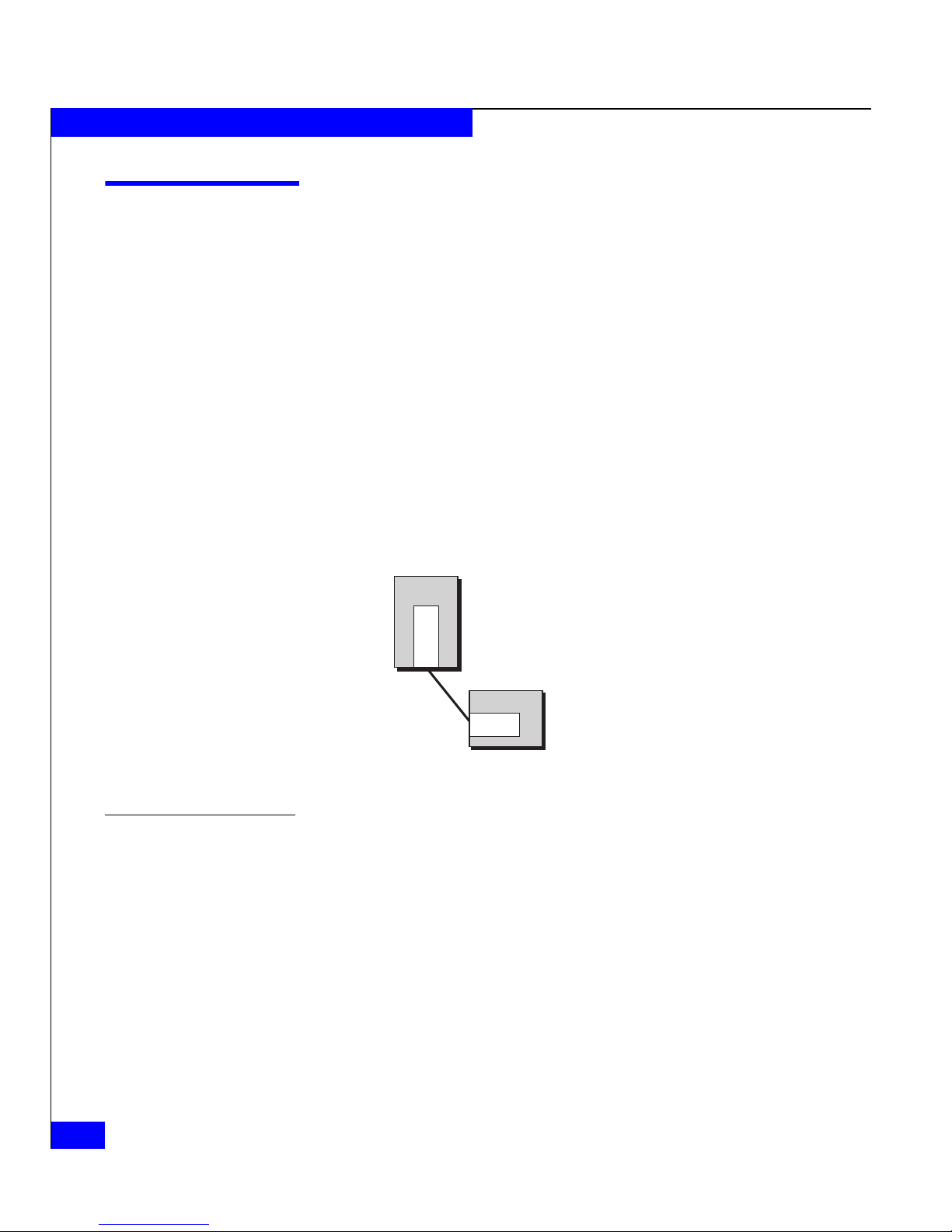
In Figure 1-4, Server 1 has access to one SP in storage systems 1 and 2;
it has no access to any other SP.
Zone
SP
SP
Storage System 1
Figure 1-4 A Switch Zone
To illustrate switch zoning, Figure 1-4 shows just one HBA per server
and one switch. Normally, such installations include multiple HBAs
per server and two or more switches.
If you do not define a zone in a switch, all adapter ports connected to
the switch can communicate with all SP ports connected to the
switch. However, access to an SP does not necessarily provide access
to the SP’s storage. Access to storage is governed by the Storage
Groups you create (explained in Storage Groups on page 1-15.
Server 1
Adapter
Server 2
Adapter
Server 3
Adapter
Switch
SP
SP
SP
Storage System 2SPStorage System 3
EMC1806
Fibre Channel switches are available with 8, 16, 32, or more ports.
They are compact units that fit into a rackmount cabinet.
Ports
Figure 1-5 Typical 16-Port Switch, Back View
EMC1807
Fibre Channel
1-7
About CX300, CX500, CX500i, and CX700 Storage Systems
If your servers and storage systems will be far apart, you can place
the switches closer to the servers or storage systems, as convenient.
A switch is technically a repeater, not a node, in a Fibre Channel loop.
However, it is bound by the same cabling distance rules as a node.
Storage Component (Storage System Enclosures)
EMC CX300, CX500, and CX700 disk-array storage systems, with
their storage processor (SPs), power supplies, and cooling hardware
form the storage component of a Fibre Channel system. The
controlling unit is a CX300 or CX500 disk processor enclosure (DPE2)
or a CX700 storage processor enclosure (SPE). A CX700 SPE, outside
of its cabinet, is shown in Figure 1-6.
1-8
EMC2434
Figure 1-6 CX700 Storage Processor Enclosure (SPE)
Each CX300 (DPE2), CX500 (DPE2), and CX700 (SPE) has two SPs.
The number of ports for each SP varies between storage systems.
Table 1-3 lists the number of ports per SP for each system.
Table 1-3 Number of Storage System Ports per SP
Storage System Front End Ports Back End Ports
CX300 2 1
CX500 2 2
CX700 4 4
EMC CLARiiON CX300, CX500, CX500i, and CX700 Storage Systems Configuration Planning Guide

About CX300, CX500, CX500i, and CX700 Storage Systems
The front-end ports communicate with switches or servers and the
back-end ports communicate with disks. Hardware details appear
later in Chapter 6.
Fibre Channel
1-9
About CX300, CX500, CX500i, and CX700 Storage Systems
iSCSI
Internet SCSI (iSCSI) is a serial protocol that uses the internet protocol
(IP) for transmission of both network and I/O data.
An iSCSI network (LAN) is a set of point-to-point connections
between nodes; each connection is made directly or through one or
more network components such as switches. Each node has its own
unique IP address, while the LAN on which the storage system
resides has a subnet mask address and a gateway address. Nodes are
connected through a LAN by Ethernet CAT 6, CAT 5E, or CAT 5
copper cables. (We recommend CAT 6 cables for gigabit Ethernet
connections.)
Each node in an iSCSI environment is either an initiator (in a server)
or a target (in the storage system). Network switches are not nodes.
Figure 1-2 shows an initiator node and a target node.
Host Adapter (Initiator)
Node
Adapter
iSCSI Connection
Figure 1-7 Nodes - Initiator and Target
iSCSI Storage Components
An iSCSI storage environment has three main components:
◆ Initiator components: servers containing host adapters, drivers,
◆ LAN components: LAN cables and LAN devices such as switches
◆ Target components: storage systems with storage processors,
Storage System (Target)
Node
SP
EMC1802a
and software.
and routers.
power supply, cooling hardware, and disks.
1-10
EMC CLARiiON CX300, CX500, CX500i, and CX700 Storage Systems Configuration Planning Guide
Initiator Components
About CX300, CX500, CX500i, and CX700 Storage Systems
The network interface card (NIC) or host bus adapter (HBA) is a
printed-circuit board that slides into an I/O slot in the server’s
cabinet. It transfers data between server memory and one or more
storage systems over the LAN using the iSCSI protocol.
LAN Components
LAN Switches A LAN switch connects all the nodes cabled to it. A switch adds
Host
Host
OR
HBA HBA
NIC NIC
EMC3060
LAN components include the network cables (CAT 6 is
recommended for Gigabit Ethernet) and network components such
as switches and routers.
serviceability and scalability to any installation; it allows online
insertion and removal of any device and maintains integrity if any
connected device fails.
Server
A
d
a
p
t
e
r
Server
A
d
a
p
t
e
r
Server
A
d
a
p
t
e
r
Storage System
Figure 1-8 Switch and Point-to-Point Connections
SP
SP
SP
Storage System
SP
EMC1805
iSCSI
1-11

About CX300, CX500, CX500i, and CX700 Storage Systems
Target Components
Target components are iSCSI storage systems, namely CX500i
disk-array storage systems, with storage processors (SPs), power
supplies, and cooling hardware. The controlling unit is a CX500i disk
processor enclosure (DPE2). Each CX500i (DPE2) has two SPs, each
with two 1-gigabit iSCSI ports. The iSCSI front-end (data) ports
communicate with switches or servers and the Fibre Channel
back-end ports communicate with disks.
1-12
EMC CLARiiON CX300, CX500, CX500i, and CX700 Storage Systems Configuration Planning Guide
About CX300, CX500, CX500i, and CX700 Storage Systems
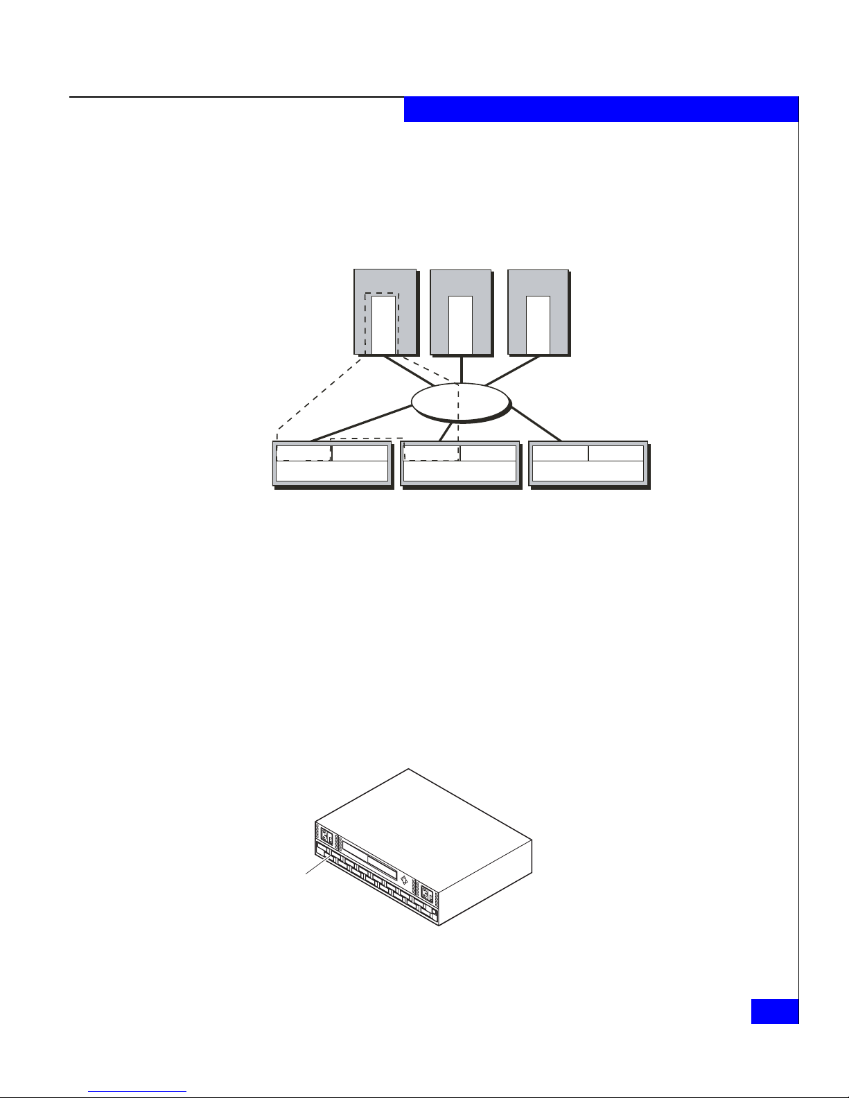
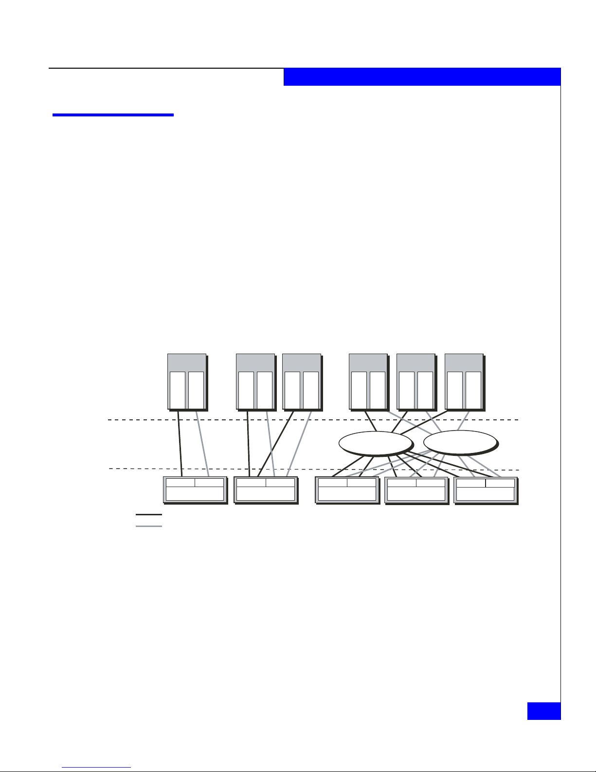
Types of Storage-System Installations
You can use a storage system in any of several types of installation:
◆ Unshared direct with one server is the simplest and least costly.
◆ Shared-or-clustered direct, with a limit of two servers, lets two
servers share storage resources with high availability.
◆ Shared switched, with two switch fabrics, lets two or more
servers share the resources of several storage systems in a storage
area network (SAN). Shared switched installations are available
in high-availability versions (two HBAs per server) or with one
HBA per server. Shared switched storage systems can have
multiple paths to each SP, providing multipath I/O for dynamic
load sharing and greater throughput.
Unshared Direct
(One or Two Servers)
Server
Component
Interconnect
Component
Storage
Component
Path 1
Path 2
Server Server Server Server Server Server
Adapter
Adapter
SP A
SP B
Storage System
Shared or Clustered
Direct (Two Servers)
Adapter
Adapter
SP A
Storage System Storage System Storage System
Adapter
SP B
Figure 1-9 Types of Storage-System Installation
Storage systems for any shared installation require EMC Access
TM
Logix
software to control server access to the storage-system LUNs.
The shared-or-clustered direct installation can be either shared (that
is, use Access Logix to control LUN access) or clustered (without
Access Logix, but with operating system cluster software controlling
LUN access).
Adapter
SP A
Shared Switched (Multiple Servers,
Multiple Paths to SPs)
Adapter
Adapter
FC Switch
or
LAN
SP B
Adapter
SP A
Adapter
FC Switch
SP B
Adapter
Adapter
or
LAN
SP A
Storage System
SP B
EMC1826a
Types of Storage-System Installations
1-13
About CX300, CX500, CX500i, and CX700 Storage Systems
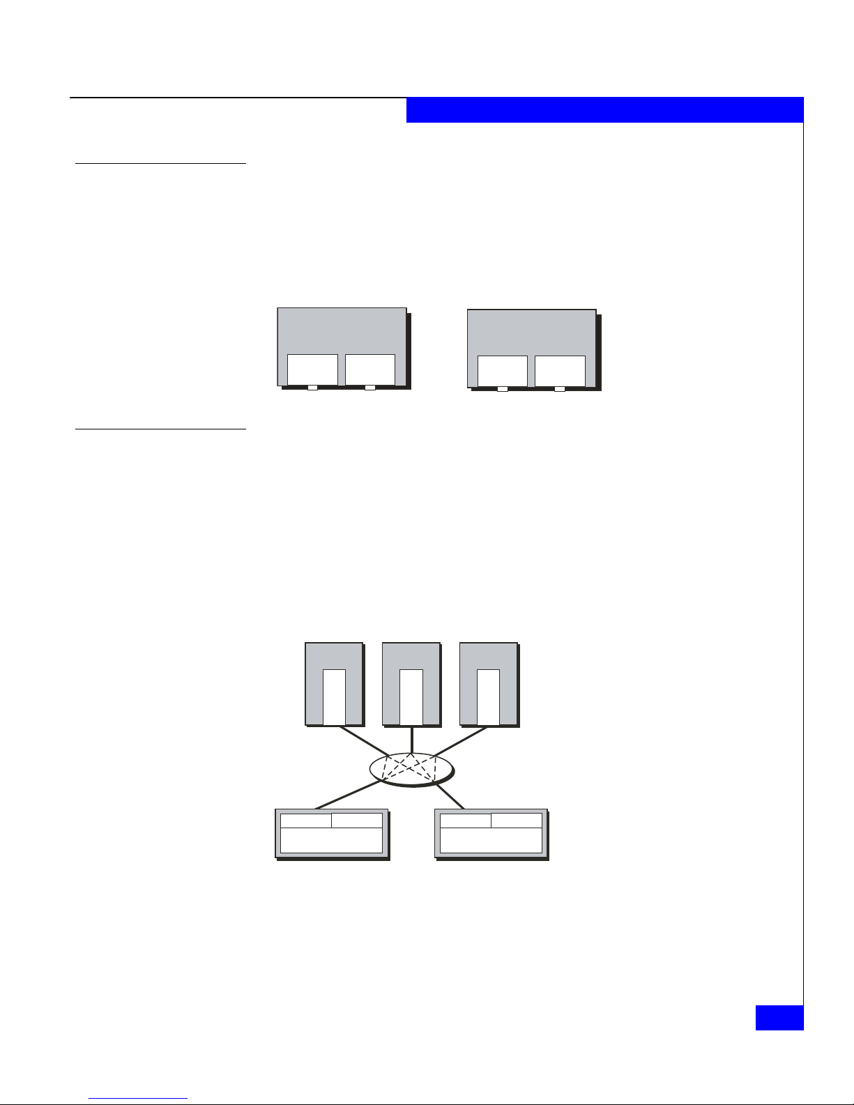
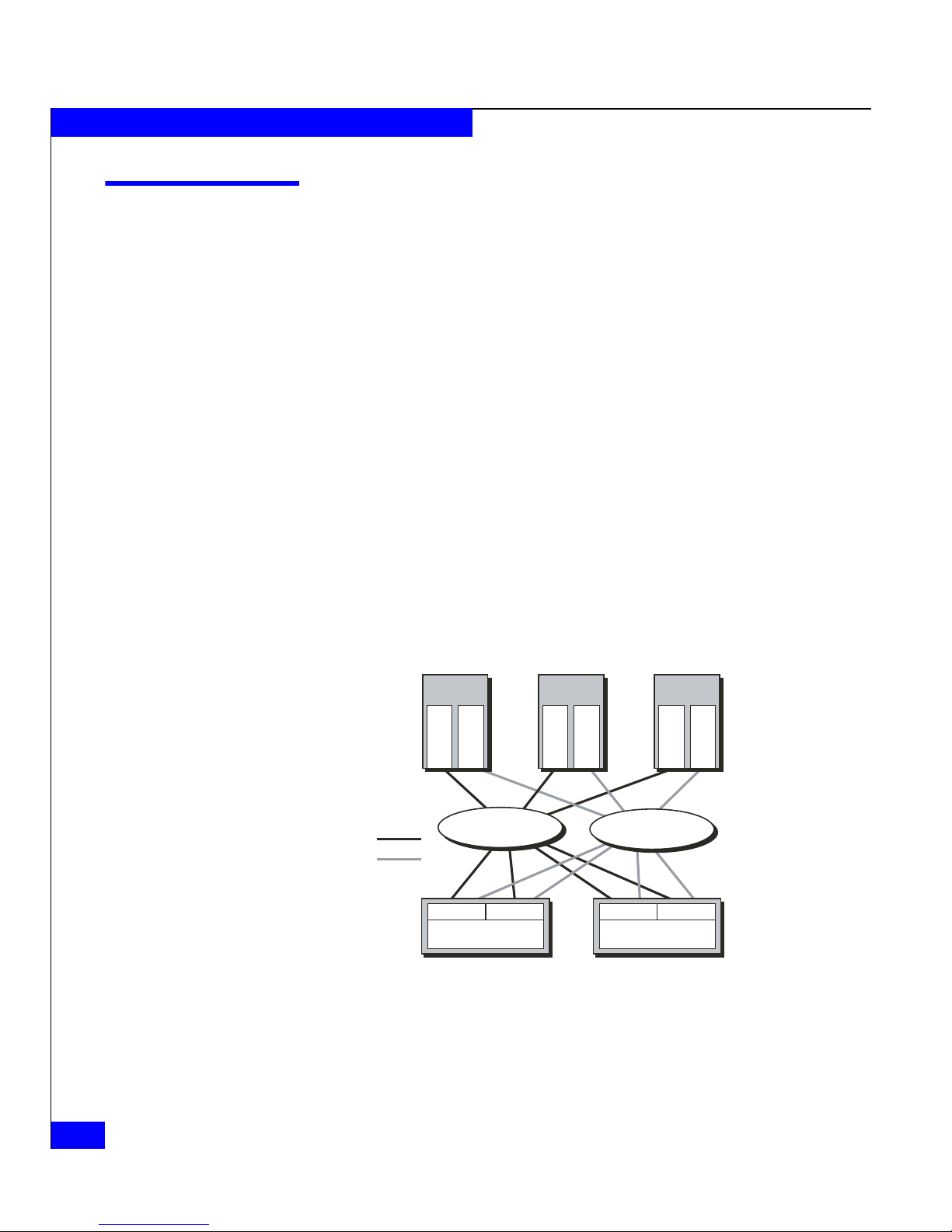
About Switched Shared Storage and SANs (Storage Area
Networks)
This section explains the features that let multiple servers share
disk-array storage systems on a SAN (storage area network).
A SAN is one or more storage devices connected to servers through
Fibre Channel switches to provide a central location for disk storage.
Centralizing disk storage among multiple servers has many
advantages, including
◆ highly available data
◆ flexible association between servers and storage capacity
◆ centralized management for fast, effective response to users’ data
storage needs
◆ easier file backup and recovery
An EMC
EMC Access Logix software to provide flexible access control to
storage-system LUNs. Within the SAN, a network connection to each
SP in the storage system lets you configure and manage it.
®
SAN is based on shared storage; that is, the SAN requires
1-14
Server Server Server
Adapter
Adapter
FC Switch
Path 1
Path 2
SP A
Storage System
Figure 1-10 Components of a SAN
or
LAN
SP B
Adapter
Adapter
Adapter
Adapter
FC Switch
or
LAN
SP A
Storage System
SP B
EMC1810b
Fibre Channel switches can control data access to storage systems
through the use of switch zoning, explained earlier on page 1-6.
EMC CLARiiON CX300, CX500, CX500i, and CX700 Storage Systems Configuration Planning Guide

About CX300, CX500, CX500i, and CX700 Storage Systems
However, switch zoning cannot selectively control data access to
LUNs in a storage system, because each SP appears as a single Fibre
Channel device to the switch fabric. So switch zoning can prevent or
allow communication with an SP, but not with specific disks or LUNs
attached to an SP. For access control with LUNs, a different solution is
required: Storage Groups.
Storage Groups
A Storage Group is one or more LUNs (logical units) within a storage
system that is reserved for one or more servers and is inaccessible to
other servers. Storage Groups are the central component of shared
storage; storage systems that are unshared do not use Storage
Groups.
When you configure shared storage, you specify servers and the
Storage Group(s) each server can read from and/or write to. Access
Logix software running in each storage system enforces the
server-to-Storage Group permissions.
More than one server can access a Storage Group if all the servers run
cluster software. The cluster software enforces orderly access to the
shared Storage Group LUNs.
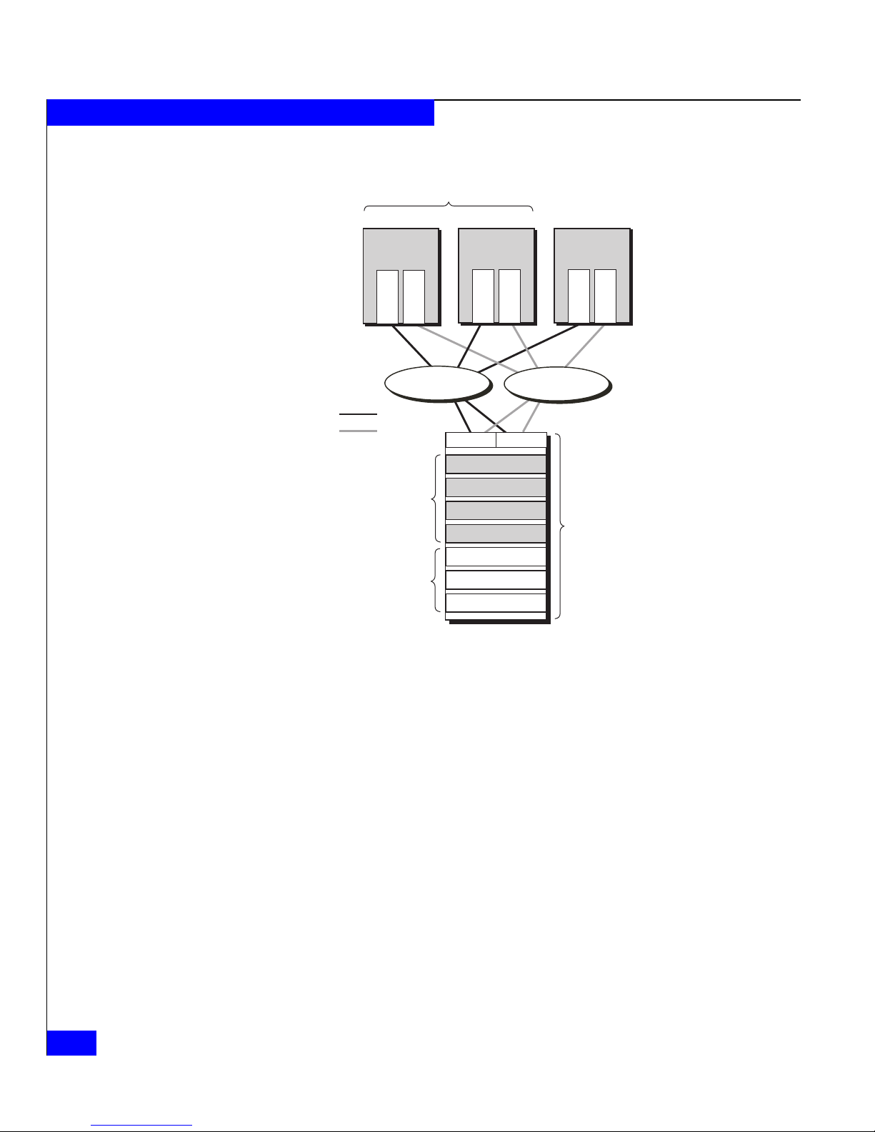
Figure 1-11 shows a simple shared storage configuration consisting of
one storage system with two Storage Groups. One Storage Group
serves a cluster of two servers running the same operating system,
and the other Storage Group serves a UNIX
®
database server. Each
server is configured with two independent paths to its data,
including separate host bus adapters, switches, and SPs, so there is no
single point of failure for access to its data.
About Switched Shared Storage and SANs (Storage Area Networks)
1-15
About CX300, CX500, CX500i, and CX700 Storage Systems
Path 1
Path 2
Cluster Storage
Group
Database Server
Storage Group
Highly available cluster
or
LAN
SP A SP B
Mail server
Operating
system A
File server
Operating
system A
Adapter
Adapter
FC Switch
Adapter
Adapter
LUN
LUN
LUN
LUN
LUN
LUN
LUN
Database
server
Operating
system B
Adapter
FC Switch
or
LAN
Physical storage
system with up to
240 disks per system
Adapter
EMC1811b
Figure 1-11 Sample Shared Storage Configuration
Access Control with Shared Storage
1-16
EMC CLARiiON CX300, CX500, CX500i, and CX700 Storage Systems Configuration Planning Guide
Access control permits or restricts a server’s access to shared storage.
Configuration access, the ability to configure storage systems, is
governed by the storage system software security mechanism: a set of
privileges based on username and password that’s stored, encrypted,
on one or more storage systems in a network.
Data access, the ability to read and write information to
storage-system LUNs, is provided by Storage Groups. During
storage-system configuration, the system administrator uses a
management utility to associate a server with one or more LUNs. The
associated LUNs compose a Storage Group.
Each server sees its Storage Group as if it were an entire storage
system, and never sees the other LUNs on the storage system.
Therefore, it cannot access or modify data on LUNs that are not part
of its Storage Group. However, you can define a Storage Group as
About CX300, CX500, CX500i, and CX700 Storage Systems
sharable (accessible by more than one server), if, as shown above in
Figure 1-11, the servers run cluster software.
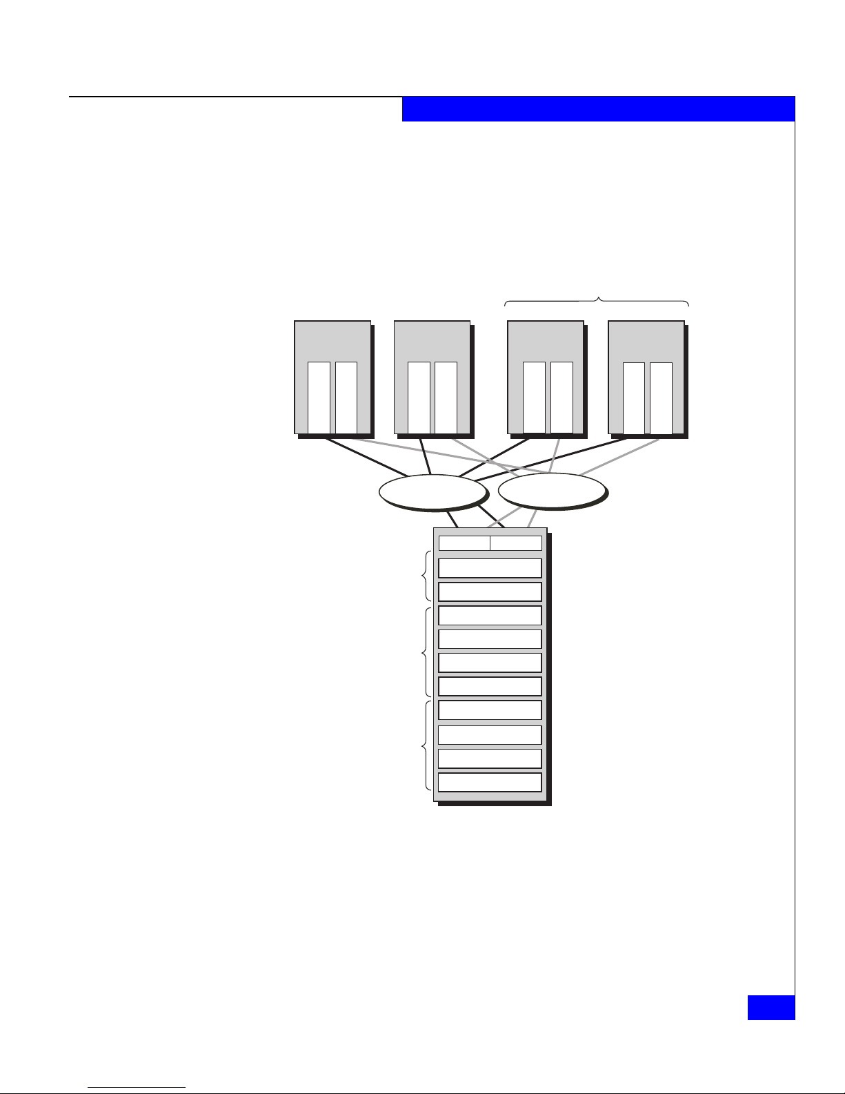
Figure 1-12 shows access control through Storage Groups. Each
server has exclusive read and write access to its designated Storage
Group.
Highly available cluster
Admin Server
Operating
system A
Adapter 00
Adapter 01
Inventory Server
Operating
system A
Adapter 02
Adapter 03
E-mail Server
Operating
system B
Adapter 04
Adapter 05
Web Server
Operating
system B
Adapter 06
Adapter 07
FC Switch
or
LAN
Admin Storage Group
Dedicated
Data access by adapters
01, 00
Inventory Storage Group
Dedicated
Data access by adapters
02, 03
E-mail and Web Server
Storage Group
Shared
Data access by adapters
04, 05, 06, 07
Figure 1-12 Data Access Control with Shared Storage
SP A SP B
LUN
LUN
LUN
LUN
LUN
LUN
LUN
LUN
LUN
LUN
FC Switch
or
LAN
EMC2403a
What Next? For information about RAID types and RAID trade-offs, continue to
the next chapter.
For information on the Navisphere
®
Manager Suite software, go to
Chapter 3.
About Switched Shared Storage and SANs (Storage Area Networks)
1-17

About CX300, CX500, CX500i, and CX700 Storage Systems
For information on the optional data replication software
(SnapView™, MirrorView™, MirrorView/Asynchronous) or data
mobility software (SAN Copy™), go to Chapter 4.
To plan LUNs and file systems, go to Chapter 5.
For details on the storage-system hardware, go to Chapter 6.
For worksheets and a description of iSCSI configurations, go to
Chapter 7.
1-18
EMC CLARiiON CX300, CX500, CX500i, and CX700 Storage Systems Configuration Planning Guide
 Loading...