

Page 1

EMC® Celerra® NS-120 System
(Single Blade)
Installation Guide
P/N 300-007-880 Rev A04
Page 2

EMC believes the information in this publication is accurate as of its publication date.
The information is subject to change without notice.
THE INFORMATION IN THIS PUBLICATION IS PROVIDED “AS IS.” EMC CORPORATION
MAKES NO REPRESENTATIONS OR WARRANTIES OF ANY KIND WITH RESPECT TO THE
INFORMATION IN THIS PUBLICATION, AND SPECIFICALLY DISCLAIMS IMPLIED
WARRANTIES OF MERCHANTABILITY OR FITNESS FOR A PARTICULAR PURPOSE.
Use, copy, or distribution of any EMC software described in this publication requires an applicable
software license.
For the most up-to-date regulatory document for your product line, go to the Technical
Documentation and Advisories section on EMC Powerlink. For the most up-to-date listing of EMC
product names, see EMC Corporation Trademarks on EMC.com.
All other trademarks used herein are the property of their respective owners.
The label, settings, and system cabling information in this document are for your reference. Paste
the Control Station label in the provided space.
Copyright © 2008-2009 EMC Corporation. All rights reserved.
Published December, 2009
Page 3
Welcome
Before you begin
The system you are about to install comes factory pre-loaded with EMC
software (DART) and CLARiiON
Software upgrade
If you bought a software maintenance contract, you are entitled to software upgrades only after the
installation, Celerra Startup Assistant (CSA), and registration have successfully completed.
Site preparation
Complete the site preparation by verifying the following activities before instal lation:
• Network connections
• Power requirements
• Rack space requirements
Default IP addresses
The system components communicate with each other using a private Internet Protocol (IP) network.
By default, this network uses the IP addresses listed in the following table.
®
storage array software (FLARE®).
®
Celerra® Network Server
If your existing IP network uses addresses on these subnets, you are required to change the private
network addresses of your Celerra Network Server to different subnets before the installation.
Internal system addresses Factory values
Primary internal network 128.221.252.100
Backup internal network 128.221.253.100
Netmask 255.255.255.0
IP address of storage processor A 128.221.252.200
IP address of storage processor B 128.221.253.201
Gateway IP address of storage processor A 128.221.252.104
Gateway IP address of storage processor B 128.221.253.104
!
For more information, refer to Celerra Tools on http://Powerlink.EMC.com
3
Page 4
Installation overview
!!
!
!!
Installation
Step 1. Order the Celerra NS-120
and prepare the site.
Step 2. Assemble and cable
the Celerra NS-120 on site.
Implementation
Step 3. Install using the
Celerra Startup Assistant.
Step 4. Register with the
service provider.
EMC®
Tutorial
CSA Installation
P/N nnn-nnn-nnn-A0n
EMC® Celerra® NS20
EMC® Celerra® NS20 System
Tutorial
CSA Installation
P/N nnn-nnn-nnn-A0n
Back
This CD contains the intellectual property of
EMC Corporation or is licensed to EMC Corporation
from third parties. Use of this CD and the intellectual
property contained herein is expressly limited to the
Cancel
Next
terms and conditions of the License Agreement.
Step 5. Configure for production.
For more information, refer to Celerra Tools on http://Powerlink.EMC.com
CNS-001465
4
Page 5

Installation steps:
Installation overview steps
1. Review and complete the Celerra worksheet,
prepared for the installation of your Celerra NS-120.
About 20 minutes.
2. If your Celerra NS-120 is to be installed in a customer-supplied rack, use this document to unpack
the system from the mini-rack shipping container, remove the reusable rails, and install the system
in your available rack.
About 40 minutes.
Note: If your Celerra NS-120 system arrived at your site in a pre-installed cabinet and is
previously cabled, verify the cabling before you begin the use of your system.
Cable your system according to the instructions and illustrations contained in this document.
Ensure that all of your cables are seated securely.
About 45 minutes.
3. When you install your Celerra NS-120, use the Celerra Startup Assistant (CSA) to pre-confi gure
your system. The latest version of the CSA can be downloaded from the Celerra Tools section on
Powerlink
About 15 minutes.
4. Register your system with the service provider. If you do not register your system now, using the
Celerra Startup Assistant, your request for support from your service provider will be delayed.
You can also register your Celerra NS-120 by downloading the Registration Wizard on Powerlink.
About 5 minutes.
®.
. The CSA is also on the Celerra Applications & Tools CD.
pages 31-32, and verify that the site is properly
Implementation step:
5. After you have registered your Celerra NS-120 system, you must confi gure the system for
production. You can use the Provisioning Wizard in the CSA, one of the several pre-packaged
implementation confi gurations based on common usages, or your own implementation using
Celerra Manager to confi gure your system. At the end of each one of these confi gurations,
your system will be ready for production.
Note: If your Celerra NS-120 system has the Fibre Channel-enabled option use
Navisphere
For more information, refer to Celerra Tools on http://Powerlink.EMC.com
®
Manager to provision storage for use by other Hosts.
5
Page 6
Unpacking the Celerra NS-120 system
If your Celerra NS-120 system was purchased and shipped in an EMC 40 Unit cabinet, (70 in.
where 1 unit = 1.75 in.), start on
correctly and securely; otherwise start unpacking your Celerra NS-120 system from the disposable
mini-rack shipping container.
page 15 of this document and confi rm that the cables are installed
For more information, refer to Celerra Tools on http://Powerlink.EMC.com
CNS-001471
6
Page 7
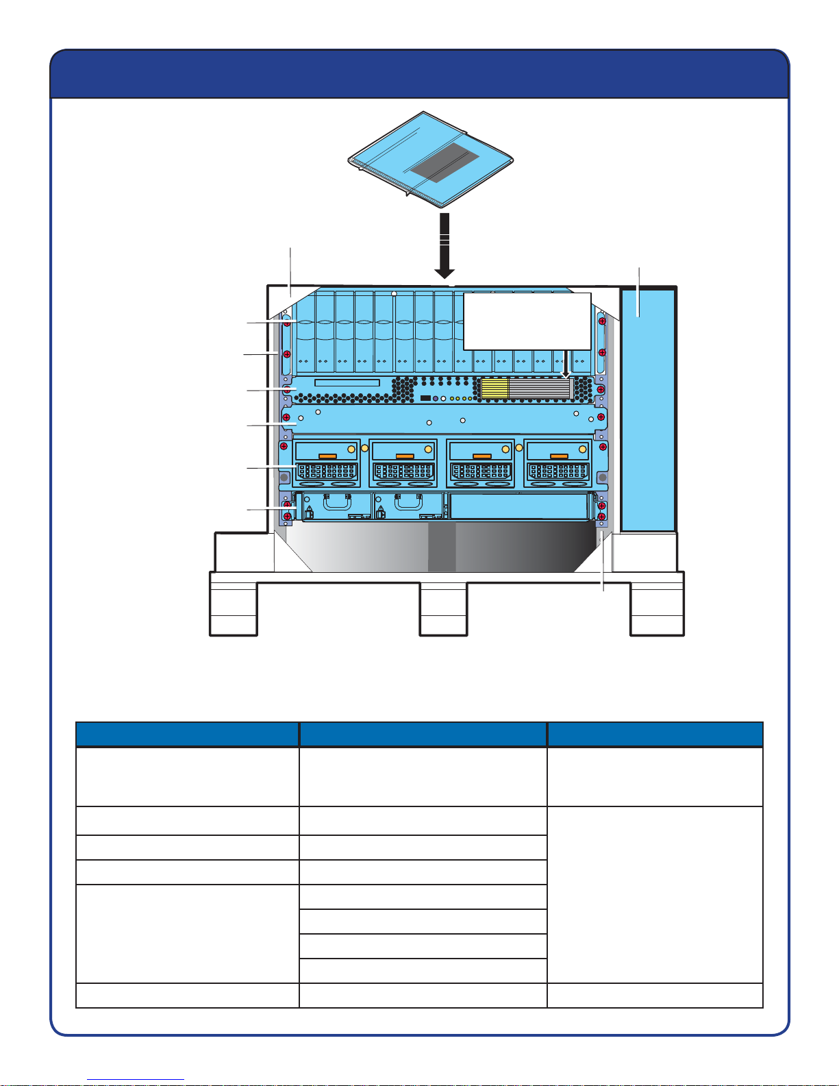
Contents of package
Shrink-wrapped Installation Guide,
environmental information and notices
Disposable mini-rack
Accessory box
Disk-array
enclosure (DAE)
Ganged rails
Control Station
(CS)
Standby power
supply (SPS)
Storage processor
enclosure (SPE)
Blade enclosure
Front
Remove this label and
paste it on the back of
the front cover of this
installation guide.
Ganged rails
CNS-001463
Note: The table represents components that are shipped with Celerra’s disposable mini-rack.
If additional accessory boxes are necessary they will be shipped separately.
Disposable mini-rack Accessory box Document inventory list
Disk-array enclosure
Ganged rails Fibre Channel cables
Control Station Power cables
Standby power supply Serial cables
Storage processor enclosure
Blade enclosure
For more information, refer to Celerra Tools on http://Powerlink.EMC.com
Standby power supply interconnect
cable kit
Crossover cables
Ethernet cables for internal network
Bezels
Hardware for non-factory installs
7
Installation guide with storage
processor options and cabling
diagrams
Environmental compliance
information and notices
Page 8
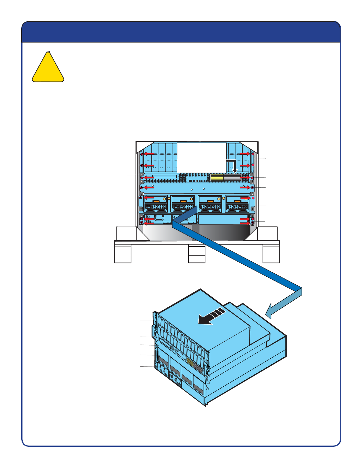
Remove components from shipping container
Caution: Two people are required to remove the components. Only remove screws holding
the components in place at this time. Do not remove the screws holding the rails in place ; this
!
1. Using a Phillips-head screwdriver, remove only 7 screws per side. Keep the removed screws
to install the components in the rack.
may cause damage to the components. Only remove one component at a time.
Remove ONLY
7 screws
per side.
Ganged rails
2. Carefully set aside each component as
it is removed from the mini-rack shipping
container.
Mini-rack
Remove this label and
paste it on the back of
the front cover of this
installation guide.
Front
Remove ONLY
7 screws
per side.
1 Disk-array
enclosure (DAE)
2 Control Station (CS)
3 Standby power
supply (SPS)
4 Storage processor
enclosure (SPE)
5 Blade enclosure
3. The reusable ganged rails
remain in the mini-rack at this time.
For more information, refer to Celerra Tools on http://Powerlink.EMC.com
1
2
3
4
5
TLA Serial Number
Model Number
DART Version
Flare Version
Unit Tested
Pre-Configu
MAC Address
SPA IP: 192.168.1.200
red
SPB IP: 192
.168.2.201
Disk-array
enclosure
Control Station
Standby power supply
Storage processor enclosure
Blade enclosure
CNS-001457
8
Page 9
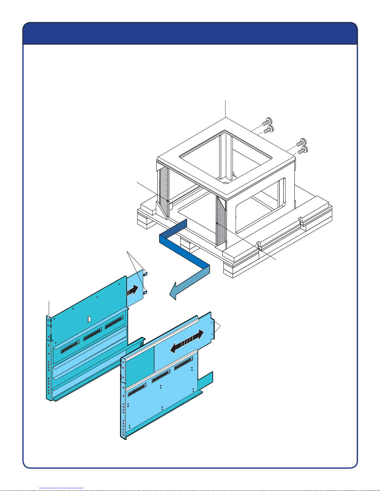
Remove ganged rails from shipping container
Remove the screws holding the component rails in place in the disposable mini-rack.
Keep the screws to install the ganged rails in your rack.
Disposable mini-rack
Remove 2 screws
each side.
Remove the ganged rails
from mini-rack.
Rail slide with extensions
Ganged rails
Threaded
screw holes
Front of rack
Remove the ganged rails
from mini-rack.
Rail slide with extensions
CNS-001459MOD
Ganged rails
For more information, refer to Celerra Tools on http://Powerlink.EMC.com
9
Page 10
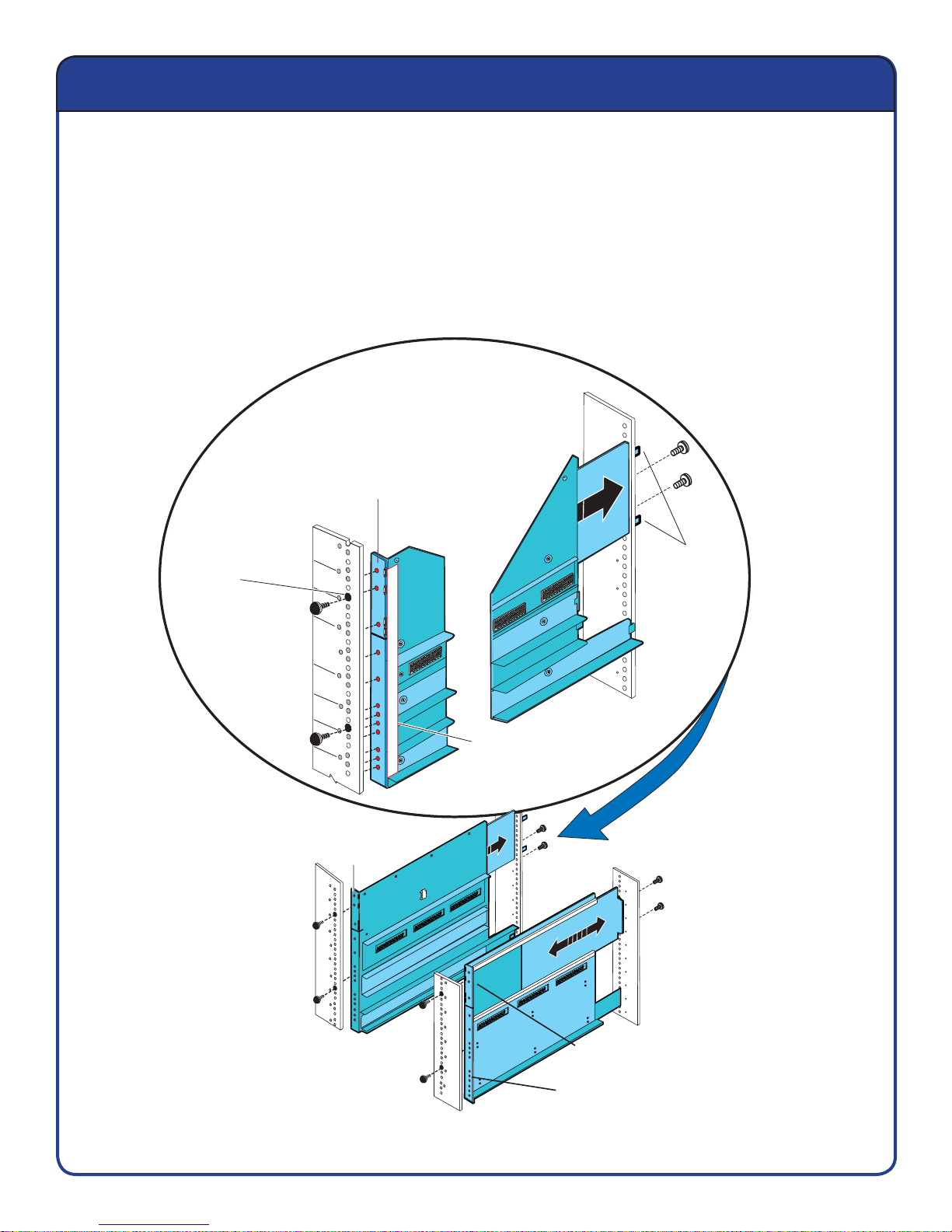
Install rails into site rack from the front
Note: The ganged rails must be aligned carefully. Two people are required to install the components.
1. Insert the rail slide and seat both rail extensions into the rear channel of your rack. We
recommend placing the top rail pin into the hole just above a National Electrical Manufactures
Association (NEMA) Unit (U) marker.
2. Align the front of the ganged rail as shown below. Insert two retention screws in the front and
back of each rail. See the following illustration.
3. Do not fully tighten the retention screws yet. Allow some adjustment space for the installation of
the components.
After inserting the rail
extensions, install 2 screws
on each side of your rack
to hold the rails in place.
Threaded
screw holes
Install the retaining screws
Detail
ganged rails
2nd screw hole
from the top of the rail
1 Unit = 1.75 in.
Install the retaining screw in
hole 2 of the rail.
1
3
7
10
13
16
17
18
19
21
22
23
Ganged rail slide
Threaded
screw holes
1
2
3
4
5
6
7
8
9
10
11
12
5th screw hole
from the bottom
extensions
of the rail
Ganged rails
Rail extensions
Rear of rack
Install 2 retaining screws
on each side of your rack
to hold the rails in place.
For more information, refer to Celerra Tools on http://Powerlink.EMC.com
Front of rack
10
2nd screw hole
from top
5th screw hole
from bottom
CNS-001455MOD
Page 11
Install components, latches, and bezels
1
2
3
4
5
1. Starting with the bottom component fi rst, install each component.
2. Fully tighten the retention screws and ensure that each component is installed securely.
3. Install the needed latches, as you install the components.
4. After all the components and latches are in place, snap on the bezels.
Disk-array enclosure (DAE)
2 bracket screws each side
Front
A and B sides
bezel bracket
2 screws per side
Control Station (CS)
Standby power supply (SPS)
Storage processor (SP)
Front
Rail catch
1 screw per side
Blade enclosure
1U latch, 2 screws each side
Right front side
Inside
Install the lower
screw first with 2 screws
on each side.
Press
Install the bottom component first.
Ensure that each component
is secure before you install the
component above it.
Inside
The indentation goes
toward the inside of
the rack.
For more information, refer to Celerra Tools on http://Powerlink.EMC.com
Snap on bezels
11
Press to install the bezel,
then release.
CNS-001461MOD NEW
Page 12

EMC Celerra NS-120 storage processor models
Typical NS-120 storage processor (SP) confi gurations. Your particular SP
confi guration may differ from the models shown here.
NS-120 Base configuration
SP B
10/100/1000 10/100/1000
SP A
123
0
0
123
0
0
MGMT B B0 B1 B2 B3 B4 MGMT A A0 A1 A2 A3 A4
NS-120 configuration with additional Fibre Channel module
SP B
10/100/1000
MGMT B
B0
1230
123
0
B1
B2
0123
B3
B4
10/100/1000
MGMT A
A0
123
0
A1
123
0
A2
NS-120 configuration with additional iSCSI modules
SP B
A3
SP A
A4
SP A
10/100/1000
0123
MGMT B
B0 B1 B2 B3 B4 MGMT A A0 A1 A2 A3 A4
For more information, refer to Celerra Tools on http://Powerlink.EMC.com
10/100/1000
123
0
CNS-001462MOD
12
Page 13

EMC Celerra NS-120 blade types
The NS-120 blade enclosure contains 1 of the 2 blade types shown
in the following illustration.
4 copper Ethernet ports
3
10/100
2
10/100
3
2
FRU label
Blade enclosure
10/100
FRU label
Blade enclosure
FRU label
Blade 2
2 10-GbE optical and 2 copper ports
046-003-710_A01
10/100
FRU label
fxg 0
fxg 1
Blade 2 CNS-001460
046-003-710_A01
For more information, refer to Celerra Tools on http://Powerlink.EMC.com
13
Page 14

EMC Celerra NS-120 confi guration
EX
EX
NS-120 single blade rear view stackup.
Disk-array enclosure
LCC B
Control Station
Standby power supply
EXP PRI
EXP
7
MODEM plug
VGA socket
PRI
4Gb
456
7
456
123
123
0
0
0
456
4Gb
A
123
PRI
7
Switch
0
456
CS
123
7
EXP
EXP PRI
MGMT
B
Power
Power
LCC A
Serial Console
Storage processor enclosure
10/100/1000 10/100/1000
123
0
0
MGMT B B0 B1 B2 B3 B4 MGMT A A0 A1 A2 A3 A4
123
123
0
0
Blade enclosure
10/100
BE 0 BE 1
Note: The blade in your Celerra system may have four Ethernet copper ports or two
10-GbE optical ports and two copper ports.
For more information, refer to Celerra Tools on http://Powerlink.EMC.com
046-002-842_A01
Blade 2
CNS-001469
14
Page 15

Cabling the EMC Celerra NS-120 system
Cable the NS-120 Fibre Channel cables.
NS-120 Base configuration with 4 Fibre Channel ports per storage processor (SP)
10/100/1000 10/100/1000
123
0
MGMT B B0 B1 B2 B3 B4 MGMT A A0 A1 A2 A3 A4
1
2
0
Blade 2 BE 0
Blade 2 BE 1
SPA A0 Port2
SPB B0 Port2
123
0
0
Storage processor enclosure (SPE)
SP B
230
1
SPB B0 Port2
12 30
12 30
SP A
12 30
1
MGMT B
B0 B1 B2 B3 B4
2 Fibre
BE0
Blade 3
Note: The blade in your Celerra system may have four Ethernet copper ports or two
10-GbE optical ports and two copper ports.
For more information, refer to Celerra Tools on http://Powerlink.EMC.com
BE1
MGMT A
Blade enclosure
15
SPA A0 Port2
A0 A1 A2 A3 A4
Blade 2 BE 0
BE1
BE0
Blade 2 BE 1
2
Blade 2
CNS-001464
Page 16

Cabling the EMC Celerra NS-120 system
Cable the Celerra NS-120 standby power supply (SPS) and MODEM ports.
Modem
Control Station
(CS)
Standby power
supply (SPS)
Storage processor
enclosure (SPE)
12 30
SPS B
CS
1
SPS B
SP B
SPS A
SPS B
12 30
SPS A
SP A
12 30
SPS A
1
2
3
Modem
SPA MGMT A
SPB MGMT B
CS
1
230
1
0
Blade 3
SPB MGMT B
3
If SPS B is installed in your system, connect the cable as shown.
For more information, refer to Celerra Tools on http://Powerlink.EMC.com
SPA MGMT A
Blade 2
Blade enclosure
2
CNS-001470
16
Page 17

Cabling the EMC Celerra NS-120 system
Cable the NS-120 internal local area network (LAN) cables.
Control Station (CS)
Standby power
supply (SPS)
Storage processor
enclosure (SPE)
1
2
3
Blade 2
Blade 2
SPB MGMT B
230
SPB MGMT B
1
CS
CS
B
A
CS
SPA MGMT A
CS
SPA MGMT A
12 30
A
B
Blade enclosure
Note: The blade in your Celerra system may have four Ethernet copper ports or two 10-GbE
optical ports and two copper ports.
For more information, refer to Celerra Tools on http://Powerlink.EMC.com
Blade 2
Blade 2
3
Blade 2
17
1
2
CNS-001466
Page 18

Cabling the EMC Celerra NS-120 system
Cable the NS-120 public local area network (LAN) cables.
Control Station
(CS)
Standby power
supply (SPS)
Storage processor
enclosure (SPE)
Blade enclosure
1
2
MGMT
To public LAN
To public LAN (customer supplied)
To public LAN
MGMT
1
A
B
Blade 3
Blade 2
cge0 cge1 cge2 cge3
2
To public LAN
CNS-001468
Note: Attach the customer-provided Ethernet cables from your public LAN starting with blade 2,
cge 0 port. Populate the cge ports as needed.
Note: The blade in your Celerra system may have four Ethernet copper ports or two
10-GbE optical ports and two copper ports.
For more information, refer to Celerra Tools on http://Powerlink.EMC.com
18
Page 19

Cabling the EMC Celerra NS-120 system
Cable the NS-120 disk-array enclosure (DAE) cables.
Storage processor (SP) A latch down (bottom SP)
Link control card (LCC) A
Pull/release tab
SPB B0 Port 0
PRI A connector
Latch side down
!
!
PRI
Pull/release tab
LCC A
#
EXP
LCC A
LCC A
PRI
B
A
B
A
!!
B
A
Disk-array
enclosure (DAE)
EXP
PRI
Storage processor (SP) B latch up (t op SP)
Link control card (LCC) B
EXP
B
A
PRI A connector
PRI
PRI B connector
!!
PRI
LCC B
LCC A PRI
PRI B connector
Latch side up
LCC B
LCC B
1
PRI
LCC B
EXPPRI
#
Control Station (CS)
SPA A0 Port 0
PRI
2
Disk-array enclosure
DAE
DAE
EXP
#
EXP
Storage processor
enclosure (SPE)
Pull/release tab
1230
SPB B0 Port 0
Standby power supply (SPS)
1230
Blade enclosure
2
123
1230
0
21FC-22FC
Pull/release tab
BE0
SPA A0 Port 0
Control Station (CS)
Standby power supply (SPS)
1230
1230
Blade enclosure
1
123
0
21FC-22FC
1230
BE0
CNS-001451MOD
For more information, refer to Celerra Tools on http://Powerlink.EMC.com
19
Page 20

Powering the EMC Celerra NS-120 system
Power Up procedure for single standby power supply (SPS) system.
Note: Verify that the cabinet circuit breakers are in the ON position. If you are installing the
NS-120 into an existing cabinet that contains other components, do not turn off the cabinet
circuit breakers. Ensure that the switch for SPS A is turned OFF.
Connect the power cables as follows:
#
A yellow circle with a number indicates the power cable number.
1. Connect power cable from the fi rst disk-array enclosure (DAE) power A to SPS A .
2. Connect power cable from the fi rst DAE power B to the left power distribution panel (PDP).
3. Connect storage processor (SP) power cable A to SPS A.
4. Connect SPS A to the right PDP.
4
3
Turn on the SPS A switch.
5. Connect SP B power cable to the left PDP.
5
Wait for the amber fault LED on each SP to turn off (approximately 3 to 4 minutes).
1
2
6. Connect the blade enclosure power cables.
6
7
7. Connect the Control Station to the left PDP.
8
Wait for the control station to power up; this may take 5 to 10 minutes.
Note: If the amber LEDs on the front or back of the storage system remain on for more than 10
minutes, make sure that the system is properly cabled.
For more information, refer to Celerra Tools on http://Powerlink.EMC.com
20
Page 21

2130
12 30
!!
!
1
0
1
0
!!
Cabling the EMC Celerra NS-120 system
Connect the NS-120 power cables in the numbered order.
Power distribution panel
(PDP)
Disk-array enclosure (DAE)
B
2
PDP
CS
SP B
8
A
4
1
SPS A
3
12 30
5
7
Blade 3
Blade enclosure
12 30
6
Blade 2
SPS A switch
SP A
CNS-001467
Note: The blade in your Celerra system may have four Ethernet copper ports or two
10-GbE optical ports and two copper ports.
For more information, refer to Celerra Tools on http://Powerlink.EMC.com
21
Page 22

Powering the EMC Celerra NS-120 system
Power Up procedure for single blade, dual standby power supply (SPS) systems
Note: Verify that the cabinet circuit breakers are in the ON position. If you are installing the NS-120
into an existing cabinet that contains other components, do not turn off the cabinet circuit breakers.
Ensure that the switches for SPS A and SPS B are turned OFF.
Connect the power cables as follows:
#
A yellow circle with a number indicates the power cable number.
1. Connect power cable from the disk-array enclosure (DAE) A power to SPS A.
2. Connect power cable from the DAE B power to SPS B.
3. Connect storage processor (SP) A power cable to SPS A.
4. Connect SP B power cable to SPS B.
4
2
3
5. Connect SPS A power cable to right PDP.
5
Turn on the SPS A switch.
6. Connect SPS B power cable to left PDP.
6
Turn on the SPS B switch.
1
7. Connect the blade enclosure power cables.
Wait for the amber fault LED on each SP to turn off (approximately 3 to 4 minutes).
8. Connect the Control Station to the left PDP.
Wait for the control station to power up; this may take 5 to 10 minutes.
Note: If the amber LEDs on the front or back of the storage system remain on for more than 10
minutes, make sure that the system is properly cabled.
For more information, refer to Celerra Tools on http://Powerlink.EMC.com
22
7
9
8
Page 23

!!
!
12 30
!!
Cabling the EMC Celerra NS-120 system
Connect the NS-120 power cables in the numbered order.
Connect the power cables as shown:
Power distribution panel
(PDP)
Disk-array enclosure
PDP
B
A
9
6
7
Blade 3
2
5
CS
1
SP A
SP A
SPS A
3
Blade 2
8
CNS-001456
SPS B
4
230
1
SP B
12 30
12 30
12 30
Blade enclosure
Note: The blade in your Celerra system may have four Ethernet copper ports or two 10-GbE
optical ports and two copper ports.
For more information, refer to Celerra Tools on http://Powerlink.EMC.com
23
Page 24

NS-120 system LEDs
!!
!
!
!
!!
1 2 30
1
2 30
1
2 30
1
2 30
Disk-array enclosure
B
A
Control Station
Standby power supply
LCC
LCC A
Blinks green
when booting.
Blinks when booting.
On when working.
SPS B
LCC B
LinkActivity
Blinks green
when booting.
A
CS
MGMT
B
Blinks green
when booting.
SPS A
Blue
when cabled.
SP A
Storage processor enclosure
Blue
when cabled.
SP B
A1 A2 A3 A4B1 B2 B3 B4 MGMT A0MGMT B0
Blade enclosure
10/100
FRU label
Blade 3
Blinks amber when booting.
Off when working.
FRU label
10/100
Blade 2
2
Blue when cabled.
3
2
Green when booted.
LinkActivity
3
CNS-001458
Note: If the amber LEDs on the front or back of the storage system remain on for more than
10 minutes, make sure that the system is properly cabled. The blades in your Celerra system may
have four Ethernet copper ports or two 10-GbE optical ports and two copper ports.
For more information, refer to Celerra Tools on http://Powerlink.EMC.com
24
Page 25

Cabling MPFS hosts over Fibre Channel
Note: If your Celerra does not use MPFS, proceed to page 28.
If you have Fibre Channel ports available for host attach, you have the option of confi guring Multi-Path File
System (MPFS) on your Celerra. This confi guration supports connecting directly to the MPFS clients, or
connecting to the MPFS clients through a switch.
To connect directly to MPFS clients, connect each client to the corresponding Fibre Channel ports on
the I/O modules in slots A2 and B2. For example, a client connected to port 0 in slot B2, should also be
connected to port 0 on slot A2.
Storage processor
10/100/1000
123
0
MGMT B
B0 B1 B2 B3 B4
123
0
23
1
0
10/100/1000
MGMT A
Clients
123
0
A0 A1 A2 A3 A4
123
0
0
CNS-001449
For more information, refer to Celerra Tools on http://Powerlink.EMC.com
25
Page 26

Cabling MPFS hosts over Fibre Channel
Note: If your Celerra does not use MPFS, proceed to page 28.
If you have Fibre Channel ports available for host attach, you have the option of confi guring Multi-Path File
System (MPFS) on your Celerra. This confi guration supports connecting directly to the MPFS clients or
connecting to the MPFS clients through a switch.
To connect directly to MPFS clients through a switch, connect the clients to the switch, and connect the
Fibre Channel ports on the I/O modules in slots A2 and B2 to the switch.
10/100/1000
123
0
123
0
Storage processor
23
1
0
10/100/1000
Switch
123
0
Clients
123
0
0
MGMT B
B0 B1 B2 B3 B4
For more information, refer to Celerra Tools on http://Powerlink.EMC.com
26
MGMT A
A0 A1 A2 A3 A4
CNS-001450
Page 27

Cabling MPFS hosts over iSCSI
Note: If your Celerra does not use MPFS, proceed to page 28.
If you have iSCSI ports available for host attach, you have the option of confi guring Multi-Path File
System (MPFS) over iSCSI on your Celerra. This iSCSI confi guration supports connecting to the
MPFS clients through a switch.
To connect to MPFS clients through a switch, connect the clients to the switch, and connect the
iSCSI ports on the I/O modules in slots A1, A2, B1, and B2.
SP B B1
Port 0
10/100/1000
SP B B1
Port 1
1
123
0
0
SP B B2
Port 0
SP B B2
Port 1
1
0
SP A A1
Port 1
SP A A1
Port 0
10/100/1000
Number of clients
Switch
SP A A2
Port 1
SP A A2
Port 0
1
123
123
0
0
1
0
MGMT B
B0 B1 B2 B3 B4
For more information, refer to Celerra Tools on http://Powerlink.EMC.com
27
MGMT A
A0 A1 A2 A3 A4
CNS-001448Storage processor
Page 28

!!
!
!
!!
NS-120 Copper cabling diagram
NS-120 single blade, copper cabling diagram.
B
A
CONTROL
STATION
SPS B
SPB MGMT B
CS
LCC B PRI
LCC A
LCC A
SPS B
LCC A PRI
LCC B
DAE
CS B
MGMT
A
CS
CS A
SPA MGMT A
MGMT
B
CONTROL
STATION
SPS A
SPS A
SPA MGMT A
SP B
SP B MGMT B
SPB B0 Port2
10/100
FRU label
230
1
SPB B0 Port0
B3
2
12 30
B4
3
MGMT A0MGMT B0
FRU label
A1 A2
SPA A0 Port2
Blade 2
10/100
Blade 2
If SPS B is installed in your system, connect the cable as shown. CNS-001454
For more information, refer to Celerra Tools on http://Powerlink.EMC.com
SPA A0 Port0
Blade 2 BE 0
A3
2
Blade 2 BE 1
SP A
A4B1 B2
3
Blade 2
28
Page 29

!!
!
!
!!
NS-120 10-GbE cabling diagram
NS-120 single blade, 10-GbE optical cabling diagram.
B
A
CONTROL
STATION
SPS B
SPB MGMT B
CS
LCC B PRI
LCC A
LCC A
SPS B
LCC A PRI
LCC B
DAE
CS B
MGMT
A
CS
CS A
SPA MGMT A
MGMT
B
CONTROL
STATION
SPS A
SPS A
SP B
SP B MGMT B
SPB B0 Port2
10/100
FRU label
230
1
SPB B0 Port0
B3
SPA MGMT A
B4
3
2
MGMT A0MGMT B0
FRU label
12 30
SPA A0 Port2
Blade 2
10/100
Blade 2
If SPS B is installed in your system, connect the cable as shown.
For more information, refer to Celerra Tools on http://Powerlink.EMC.com
A1 A2
SPA A0 Port0
fxg 0
fxg 1
A3
Blade 2 BE 1
Blade 2 BE 0
SP A
A4B1 B2
1
0
Blade 2
CNS-001453
29
Page 30

EMC Celerra NS-120 system notes
30
Page 31

Celerra Startup Assistant worksheet
Verify that the site is properly prepared for your Celerra System. Complete the worksheet and
use the information to verify the values when you run the Celerra Startup Assistant (CSA).
Note: The CSA pre-populates values based on auto-discovery from your Windows client.
Shaded areas are values that will be auto-discovered based on your system and network
environment; if auto-discovery fails, you need to provide the information manually.
1. Record the external network settings for the Control Station.
Control Station hostname
Control Station static IP address
Netmask
Gateway
DNS domain
Primary DNS server
Secondary DNS server
NTP server
TimeZone
2. The passwords for the root user/system backend administrator and NAS administrator
are default values. These default values should be changed as soon as possible for
security reasons.
root_password (default value = nasadmin)
NAS administrator (default value = nasadmin)
3. The appropriate blade external network settings are auto-discovered.
Blade DNS domain
Blade primary DNS server
Blade secondary DNS server
Blade NTP server
For more information, refer to Celerra Tools on http://Powerlink.EMC.com
31
Page 32

Celerra Startup Assistant worksheet
4. Record the storage processor external network IP addresses.
Note: Public IP addresses for your storage processors are required to use the Navisphere Service
Taskbar on both Fibre Channel (FC) and non-FC enabled models for routine array maintenance. The
IP addresses must be on the same subnet as the Control Station.
Storage processor A IP address
Storage processor B IP address
5. If applicable, confi gure service provider/customer notifi cation information.
Note: The dial-in modem number is the phone number for the line that connects to the modem. This
is the local number that is used by the service provider to dial into your system.
Note:
Email will not work without a DNS server.
Service provider/
customer notifi cation
Email server (recommended)
Recipient email addresses (optional)
Site information Site ID (optional) (party name)
Dial-in modem no. (optional)
6. Record the licenses that you have purchased.
CIFS (Windows)
NFS (Linux)
iSCSI
For more information, refer to Celerra Tools on http://Powerlink.EMC.com
32
Page 33

Celerra Startup Assistant
Install the Celerra Startup Assistant (CSA)
Before installing the CSA, verify the following requirements:
• Access to the Powerlink website (preferred) or the Celerra Network Server Applications and Tools CD
is available.
• Windows-based client computer is on the same subnet (customer network) as the
Celerra Management Control Station.
• The computer must have at least 100 MB of free space. Internet connectivity is recommended.
To obtain and install the CSA, perform the following numbered steps:
Note: On your computer, disable any fi rewall software, pop-up blockers, virtual private network
(VPN) interfaces, and VMware® network interfaces before running the CSA.
1. Download the CSA from a link on the Celerra Tools page of the Powerlink website. If you do not
have access to the Powerlink website, insert the Celerra Network Server Applications and Tools
CD into your computer.
2. In the EMC Product Installation window, click Celerra Startup Assistant to install the CSA on
your computer.
Network
Load the Apps & Tools CD in
either a laptop or PC tower.
Tutorial CD
CSA Installation
EMC® Celerra® NS40 System
P/N nnn-nnn-nnn-A0n
All Rights Reserved
Copyright© 2nnn EMC Corporation
This CD contains the intellectual property of
EMC Corporation or is licensed to EMC Corporation
from third parties. Use of this CD and the intellectual
property contained herein is expressly limited to the
terms and conditions of the License Agreement.
For more information, refer to Celerra Tools on http://Powerlink.EMC.com
CNS-001426
33
Page 34

Celerra Startup Assistant
Run the Celerra Startup Assistant (CSA)
To run the CSA:
3. Double-click the Celerra Startup Assistant shortcut on the desktop or go to
C:\ProgramFiles\EMC\CSA\startup\launch.bat.
4. Click Install. The Celerra Startup Assistant guides you through the remaining steps.
5. Then confi gure your system as described in “Step 5: Confi gure for Production.”
Step 5: Confi gure for Production
Now that the CSA pre-confi guration is complete, you must confi gure the system
for production. You can use the Provisioning Wizard in the CSA, one of several
pre-packaged implementation confi gurations based on common usages, or your
own implementation using Celerra Manager to confi gure your system.
At the end of each of these confi gurations, your system will be ready for
production.
Common implementations include:
• Create CIFS shares
• Create iSCSI LUNs
• Create NFS exports
• Set up MPFS-enabled systems
• Add additional hosts for Fibre Channel enabled systems
• Perform Common Post-CSA tasks
Go to the Celerra Tools page for the NS-120 on Powerlink and select Step 5:
Confi gure for Production for more information.
For more information, refer to Celerra Tools on http://Powerlink.EMC.com
34
Page 35

Page 36

 Loading...