

Page 1
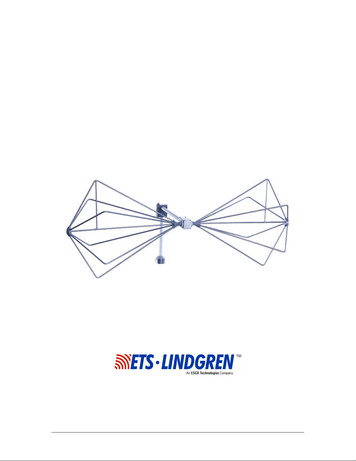
Model 3110B
Biconical Antenna
MANUAL
© EMC TEST SYSTEMS, L.P. – MARCH 2002 REV F – PN 399108
Page 2

MODEL 3110B BICONICAL ANTENNA
EMC Test Systems, L.P. reserves the right to make changes to any product described herein in order to
improve function, design or for any other reason. Nothing contained herein shall constitute EMC Test
Systems, L.P. assuming any liability whatsoever arising out of the application or use of any product or
circuit described herein. EMC Test Systems, L.P. does not convey any license under its patent rights or the
rights of others.
© Copyright 2002 by EMC Test Systems, L.P. All Rights Reserved.
No part of this document may be copied by any means
without written permission from EMC Test Systems, L.P.
E-MAIL & INTERNET
Support@ets-lindgren.com
http://www.ets-lindgren.com
USA
1301 Arrow Point Dr., Cedar Park, TX 78613
P.O. Box 80589, Austin, TX 78708-0589
Tel 512.531.6400 Fax 512.531.6500
FINLAND
Euroshield OY
Mekannikontie 1
27510, Eura, Finland
Tel 358.2.838.3300
Fax 358.2.865.1233
SINGAPORE
Lindgren RF Enclosures Asia-Pacific
87 Beach Road
#06-02 Chye Sing Building
Singapore 189695
Tel 65.536.7078 Fax 65.536.7093
© EMC TEST SYSTEMS, L.P. – MARCH 2002
REV F – PN 399108
Page 3

MODEL 3110B BICONICAL ANTENNA
Table of Contents
INTRODUCTION.................................................................................................................................. 1
ASSEMBLY INSTRUCTIONS..............................................................................................................1
MOUNTING INSTRUCTIONS............................................................................................................. 2
APPLICATION...................................................................................................................................... 3
TYPICAL DATA....................................................................................................................................4
SPECIFICATIONS................................................................................................................................ 6
MAINTENANCE................................................................................................................................... 7
WARRANTY STATEMENT................................................................................................................. 8
© EMC TEST SYSTEMS, L.P. – MARCH 2002
REV F – PN 399108
Page 4

MODEL 3110B BICONICAL ANTENNA
© EMC TEST SYSTEMS, L.P. – MARCH 2002
REV F – PN 399108
Page 5

MODEL 3110B BICONICAL ANTENNA Introduction
INTRODUCTION
The ETS-Lindgren EMCO brand Model 3110B Biconical
Antenna is specifically designed for radiated emissions
testing. This high performance, receive only, antenna
operates with in a frequency range of 30 to 300 MHz.
The biconical elements are made from aluminum rods and
are welded into a fixed assembly. The elements mount onto
a balun network which is fabricated of aluminum and the
necessary impedance-matching components. Its lightweight
construction provides for ease in portability and storage.
ASSEMBLY INSTRUCTIONS
The Model 3110B consists of the following (shipped
unassembled):
1 ea. Balun
2 ea. Biconical Elements
2 ea. Belleville Washers (In a small plastic bag)
1 ea. Mounting Clamp
Step 1. After carefully unpacking all of the components, take one
of the belleville washers and slide it onto the threaded
screw end of one of the biconical elements.
Step 2. Line up the screw threads with the receptacle hole on the
balun and turn the biconical element until it is firmly
secured in the balun. Be careful not to cross-thread this
connection or permanent damage to the joint could occur.
© EMC TEST SYSTEMS, L.P. – MARCH 2002 1
REV F – PN 399108
Page 6

Mounting Instructions MODEL 3110B BICONICAL ANTENNA
Step 3. Repeat Steps 1 and 2 with the other washer and biconical
element.
Now you are ready to mount the antenna on a tripod for
testing.
Belleville Washer
Biconical Element
Output Connector
Balun
Clamp (Open Position)
MOUNTING INSTRUCTIONS
The mounting clamp of the Model 3110B uses standard
7/8x14 threads and comes with a 1/4x20 thread adapter for
versatility when connecting to an ETS tripod or most other
tripods for support.
After the mounting clamp is attached to a tripod, unscrew
the latch and open the clamp. Insert the balun of the 3110B
into the clamp and close the top over the balun. Move the
screw latch to the closed position and tighten, so the balun
is held securely. The cable can now be attached to the
output connector.
2 © EMC TEST SYSTEMS, L.P. – MARCH 2002
REV F – PN 399108
Page 7

MODEL 3110B BICONICAL ANTENNA Application
APPLICATION
The Model 3110B is ideally suited for swept site
attenuation measurements per ANSI and FCC
specifications. Also, the Model 3110B can be used for
horizontal as well as vertical site attenuation measurements.
A 20 dB pre-amp is recommended in line with the receive
antenna to minimize the required transmitted power and to
reduce the possibility of saturation of the transmitting
antenna. The maximum continuous input power to the
Model 3110B is 250 mW.
When the 3110B is used vertically, the same element
orientation need not be maintained from measurement to
measurement. The Model 3110B exhibits excellent
symmetrical performance and test repeatability is assured
by the balun design.
Each antenna is calibrated during manufacturing. The
results of the calibration are tabulated and included with
this manual as gain and antenna factor vs frequency for use
in Specification Compliance Testing. Typical data for the
Model 3110B can be found in the next section.
© EMC TEST SYSTEMS, L.P. – MARCH 2002 3
REV F – PN 399108
Page 8

Typical Data MODEL 3110B BICONICAL ANTENNA
3 m
10 m
dB 1/m
3 m
10 m
dB
TYPICAL DATA
1 m
25
20
15
10
5
30 60 90 120 150 180 210 240 270 300
Frequency (Mhz)
Model 3110B Antenna Factor
10
1 m
5
0
-5
-10
-15
-20
30 60 90 120 150 180 210 240 270 300
Frequency (Mhz)
Model 3110B Gain
4 © EMC TEST SYSTEMS, L.P. – MARCH 2002
REV F – PN 399108
Page 9

MODEL 3110B BICONICAL ANTENNA Typical Data
15
13
11
9
7
5
3
1
30 60 90 120 150 180 210 240 270 300
Frequency (Mhz)
Model 3110B VSWR
200
180
160
140
degrees
120
100
80
60
40
30 60 90 120 150 180 210 240 270 300
Frequency (Mhz)
Model 3110B Half Power Beamwidth
© EMC TEST SYSTEMS, L.P. – MARCH 2002 5
REV F – PN 399108
Page 10

Specifications MODEL 3110B BICONICAL ANTENNA
SPECIFICATIONS
Electrical
Frequency Range 30 to 300 MHz
VSWR Ratio (AVG) 2.0:1
Maximum Continuous Power 250 mW
Peak Power NA
Impedance
Connector Type N female
50 V
Physical
Width 132.1 cm
52.0 in
Depth 55.9 cm
22.0 in
Diameter 52.0 cm
20.5 in
Weight 2.7 kg
6.0 lb
NOTE: ETS-Lindgren recommends using a 6DB pad
attached to the end of the antenna, otherwise high VSWR
may occur.
6 © EMC TEST SYSTEMS, L.P. – MARCH 2002
REV F – PN 399108
Page 11

MODEL 3110B BICONICAL ANTENNA Maintenance
MAINTENANCE
To ensure reliable and repeatable long-term performance,
annual recalibration of your antenna by ETS-Lindgren’s
experienced technicians is recommended. Our staff can
recalibrate almost any type or brand of antenna. Please call
to receive a Service Order Number prior to sending an
antenna to us for calibration.
For more information about our calibration services or to
place an order for antenna calibration visit our calibration
website at http://www.antennacalibration.com/.
© EMC TEST SYSTEMS, L.P. – MARCH 2002 7
REV F – PN 399108
Page 12

Warranty Statement MODEL 3110B BICONICAL ANTENNA
WARRANTY STATEMENT
EMC Test Systems, L.P., hereinafter referred to as the Seller, warrants that standard EMCO
products are free from defect in materials and workmanship for a period of two (2) years from
date of shipment. Standard EMCO Products include the following:
v Antennas, Loops, Horns
v GTEM cells, TEM cells, Helmholtz Coils
v LISNs, PLISNs, Rejection cavities & Networks
v Towers, Turntables, Tripods, & Controllers
v Field Probes, Current Probes, Injection Probes
If the Buyer notifies the Seller of a defect within the warranty period, the Seller will, at the Seller’s
option, either repair and/or replace those products that prove to be defective.
There will be no charge for warranty services performed at the location the Seller designates.
The Buyer must, however, prepay inbound shipping costs and any duties or taxes. The Seller will
pay outbound shipping cost for a carrier of the Seller’s choice, exclusive of any duties or taxes. If
the Seller determines that warranty service can only be performed at the Buyer’s location, the
Buyer will not be charged for the Seller’s travel related costs.
This warranty does not apply to:
v Normal wear and tear of materials
v Consumable items such as fuses, batteries, etc.
v Products that have been improperly installed, maintained or used
v Products which have been operated outside the specifications
v Products which have been modified without authorization
v Calibration of products, unless necessitated by defects
THIS WARRANTY IS EXCLUSIVE. NO OTHER WARRANTY, WRITTEN OR ORAL, IS
EXPRESSED OR IMPLIED, INCLUDING BUT NOT LMITED TO, THE IMPLIED WARRANTIES
OF MERCHANTABILITY AND FITNESS FOR A PARTICULAR PURPOSE. THE REMEDIES
PROVIDED BY THIS WARRANTY ARE THE BUYER’S SOLE AND EXCLUSIVE REMEDIES.
IN NO EVENT IS THE SELLER LIABLE FOR ANY DAMAGES WHATSOEVER, INCLUDING
BUT NOT LIMITED TO, DIRECT, INDIRECT, SPECIAL, INCIDENTAL, OR CONSEQUENTIAL
DAMAGES, WHETHER BASED ON CONTRACT, TORT, OR ANY OTHER LEGAL THEORY.
Note: Please contact the Seller’s sales department for a Return Materials Authorization (RMA)
number before shipping equipment to us.
8 © EMC TEST SYSTEMS, L.P. – MARCH 2002
REV F – PN 399108
 Loading...