

Page 1
AX4-5 Series
Hardware and Operational
Overview
January 4, 2010
This overview describes the major hardware features of AX4-5 series
storage systems.
For greater clarity, the illustrations in this document show the storage-system
chassis independent of a cabinet or deskside mounting
Topics include
Storage-system components........................................................... 2
Disk and filler modules.................................................................. 5
Storage processors (SPs)................................................................. 7
Link control cards (LCCs) .............................................................. 8
Power/cooling modules ................................................................ 9
Standby power supplies (SPSs)....................................................... 10
Powerup and powerdown sequence ............................................... 11
Status lights and indicators ............................................................ 15
1
Page 2

Storage-system c
omponents
The AX4-5 series s
torage system consists of rack-mountable
storage-system e
nclosures, 3.5 inches (2U) high, that contain 4 to 12
serial advanced t
echnology attachment (SATA) or serial attached SCSI
(SAS) disk drive
s.
The AX4-5 and AX4
-5SC storage systems use a Fibre Channel arbitrated
loop (FC-AL) or F
ibre Channel switch (FC-SW) as an interconnect
interface to ho
st servers. The AX4-5i and AX4-5SCi storage systems use
the Internet Sm
all Computer System Interface (iSCSI) protocol.
The AX4-5 and AX4-5SC are also called the AX4-5F and AX4-5FSC, respectively.
Models with four Fibre Channel host ports per controller are called AX4–5F8
or AX4–5FX, and AX4–5SCF4 or AX4–5FSCX. The AX4-5i and AX4-5SCi are
also called the AX4-5I and AX4-5ISC, respectively.
Navisphere® management software manages the storage systems from
any qualified workstation on a shared Ethernet LAN. Sophisticated
RAID (redundant array of independent disk) technology and data
caching prevent data loss in case of component failure. Redundant
hardware options provide levels of high availability usually restricted
to much larger (and more expensive) storage systems. Besides
economical disks, the AX4-5 series storage systems include the
following major components:
A disk-processor enclosure (DPE-AX). A DPE-AX contains one
(AX4-5SC or AX4-5SCi) or two (AX4-5 or AX4-5i) storage processors
(SPs), each with:
z One dual-inline memory module (DIMM)
z One serial port (mini DB9 connector) for service
z One 10/100/1000 Ethernet LAN port (RJ45 connector) for
management
z For the AX4-5 or AX4-5i, one serial port for connection to a
standby power supply (SPS)
z One input/output (I/O) module per SP, each with:
− For the AX4-5 or AX4-5SC, two or four 4-Gbps Fibre Channel
host ports with small form factor pluggable (SFP) connectors
2
Hardware and Operational Overview
Page 3
− For the AX4-5i or AX4-5SCi, two Gigabit Ethernet (GigE)
ports
Two power supply/system cooling (power/cooling) modules
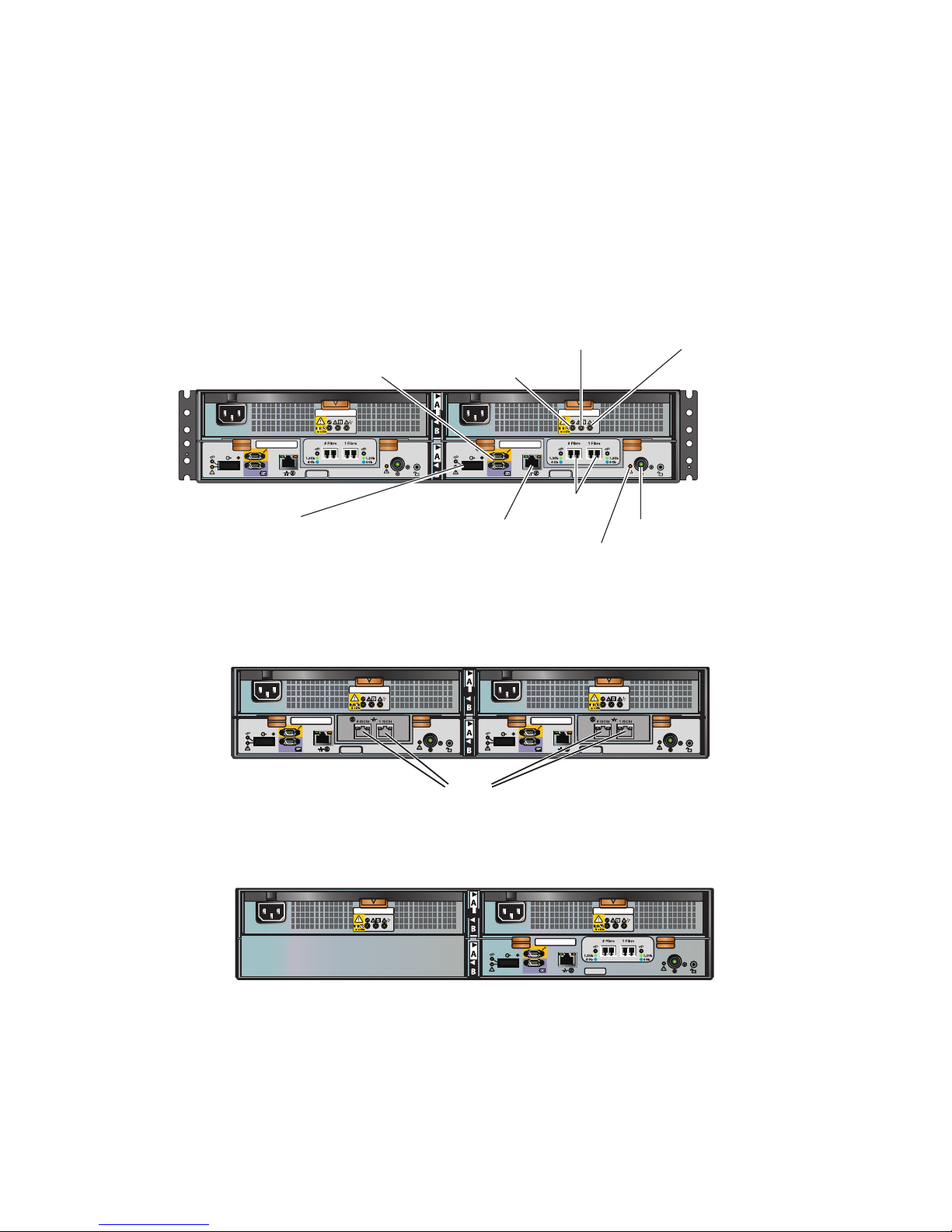
Figure 1 shows an AX4-5 DPE-AX, which has Fibre Channel I/O
modules.
FRU Label FRU Label
CL3914
Expansion DAE
SPS management
Power/cooling module
cooling fault LED
Power supply
fault LED
Power supply on
Fibre
SP service
SP management
SP fault LED
SP power LED
Figure 1
AX4-5 DPE-AX (rear view – two FC port version)
Figure 2 shows an AX4-5i DPE-AX, which has iSCSI instead of Fibre
Channel I/O modules.
FRU Label FRU Label
CL3771
iSCSI
Figure 2
AX4-5i DPE-AX (rear view)
Figure 3 shows an AX4-5SC DPE-AX with a single storage processor.
FRU Label FRU Label
CL3853
Figure 3 AX4-5SC DPE-AX (rear view — two FC port version)
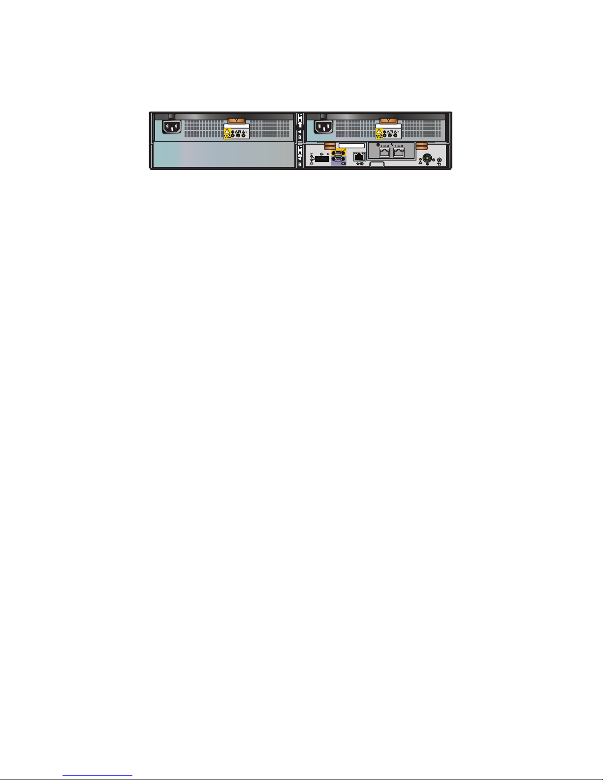
Figure 4 shows an AX4-5SCi with a single storage processor.
Hardware and Operational Overview
3
Page 4
FRU Label FRU Label
CL3854
Figure 4
AX4-5SCi DPE-AX (rear view)
AX4-5 and AX4-5i systems include a standby power supply (SPS); a
second SPS is optional. AX4-5 and AX4-5i systems support as many as
four optional disk array enclosures (DAE-AXs). Like the DPE-AX, each
DAE-AX includes two power/cooling modules and can contain a total
of twelve disk drives. Instead of SPs, a DAE-AX has two link control
cards (LCCs) that manage disks on a single redundant back-end bus.
You can install, upgrade, or replace all of the major storage-system
components without professional assistance.
4
Hardware and Operational Overview
Page 5

Disk and filler mo
dules
Each DPE-AX inclu
des at least four hard disk drives. The first four
disks, marked 0-3
, are system disks (sometimes called vault disks) and
contain vital sof
tware specific to the physical slot they occupy in the
chassis. Do not m
ove a system disk from its assigned slot to another slot.
Remove a system d
isk only if you need to replace it because it failed.
SN:1234ABCD1234ABC
123 BPS
PN:123456789 REV 123
SATA
SATA
500
500
GB
GB
7.2K RPM
7.2K RPM
SN:1234ABCD1234ABC
123 BPS
PN:123456789 REV 123
SATA
SATA
500
500
GB
GB
7.2K RPM
7.2K RPM
SN:1234ABCD1234ABC
123 BPS
PN:123456789 REV 123
SATA
SATA
500
500
GB
GB
7.2K RPM
7.2K RPM
SN:1234ABCD1234ABC
123 BPS
PN:123456789 REV 123
SATA
SATA
500
500
GB
GB
7.2K RPM
7.2K RPM
SN:1234ABCD1234ABC
123 BPS
PN:123456789 REV 123
SATA
SATA
500
500
GB
GB
7.2K RPM
7.2K RPM
SN:1234ABCD1234ABC
123 BPS
PN:123456789 REV 123
SATA
SATA
500
500
GB
GB
7.2K RPM
7.2K RPM
SN:1234ABCD1234ABC
123 BPS
PN:123456789 REV 123
SATA
SATA
500
500
GB
GB
7.2K RPM
7.2K RPM
SN:1234ABCD1234ABC
123 BPS
PN:123456789 REV 123
SATA
SATA
500
500
GB
GB
7.2K RPM
7.2K RPM
SN:1234ABCD1234ABC
123 BPS
PN:123456789 REV 123
SATA
SATA
500
500
GB
GB
7.2K RPM
7.2K RPM
SN:1234ABCD1234ABC
123 BPS
PN:123456789 REV 123
SATA
SATA
500
500
GB
GB
7.2K RPM
7.2K RPM
SN:1234ABCD1234ABC
123 BPS
PN:123456789 REV 123
SATA
SATA
500
500
GB
GB
7.2K RPM
7.2K RPM
SN:1234ABCD1234ABC
123 BPS
PN:123456789 REV 123
SATA
SATA
500
500
GB
GB
7.2K RPM
7.2K RPM
CL3880
Figure 5 DPE-AX syste
m(vault)disks
If a drive fails, you can replace it with another while the storage system
continues running; software rebuilds the contents of the original disk
onto its replacement.
DPE-AX and DAE-AX chassis have twelve slots for disk modules. Any
unoccupied disk module slot requires a filler module to maintain air
flow.
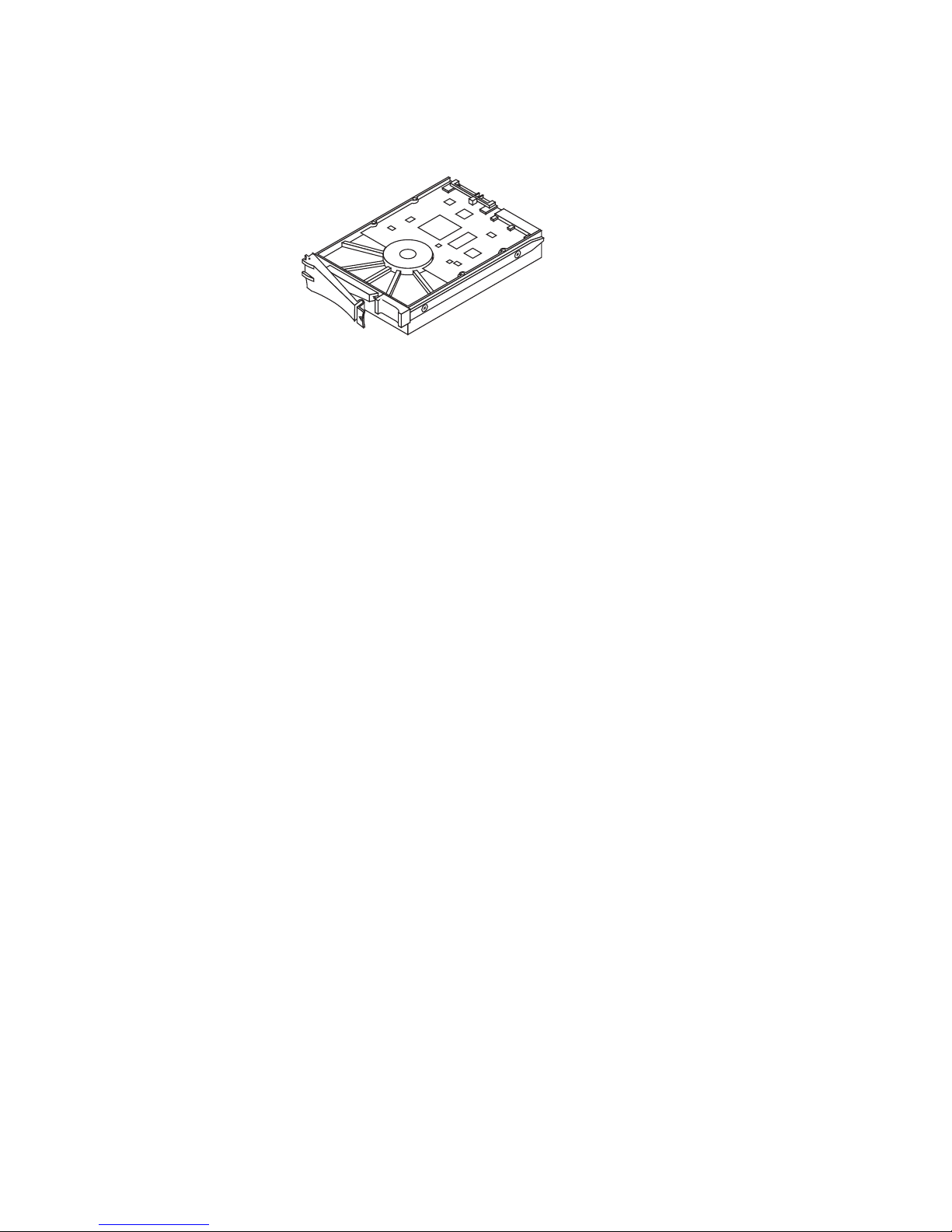
Disk modules
Each disk module, shown in Figure 6, consists of one disk drive in a
carrier. You can add or remove a disk module while the storage system
is powered up, but you should exercise special care when removing
drives while they are in use.
Hardware and Operational Overview
5
Page 6
EMC2830
Figure 6 Disk module
Disk drives
The disk drives
are standard 3.5-inch (8.75-cm) by 1.0-inch (2.54-cm)
serial advanc
ed technology attachment (SATA) or serial attached
SCSI (SAS) dri
ves. AX4–5 systems also support 2.5–inch SAS drives
mounted in 3.5
–inch drive carriers. For a detailed list of supported
disk drives a
nd the minimum revision of the FLARE® operating
environment
(OE) that supports each disk, refer to the Disk and FLARE
OE Matrix und
er “Technical description” on the Learn page on the
storage-sy
stem support website or contact your service provider.
Drive carri
er
The disk dri
ve carrier is a plastic assembly that provides smooth,
reliable co
ntact with the enclosure slot guides and system board
connectors
. It has a handle with a latch and spring clips. The latch
holds the d
iskmoduleinplacetoensureproperconnectionwiththe
connector
s.
6
Hardware and Operational Overview
Page 7

Storage processo
rs (SPs)
The storage proce
ssor (SP) is the storage system’s intelligent component
andactsastheinp
ut/output (front end) and data storage (back end)
control center. B
esides the processor board and memory DIMM, each
SP includes an I/
O module that determines the connection protocol
to host servers.
DPE-AX systems w
ith two SPs support write caching for increased
performance. T
he redundant storage processors also provide high
availability s
hould one SP fail or lose power.
Hardware and Operational Overview
7
Page 8

Link control card
s (LCCs)
Optional disk arr
ay enclosures (DAE-AXs) do not include SPs, but use
link control card
s (LCCs) to support additional disk capacity. The LCCs
in each DAE-AX con
nect to expansion ports on SPs or other LCCs with
serial-attache
d SCSI (SAS) expansion cables to create a redundant
back-end bus tha
t can support both SATA and SAS drives. Each LCC
includes a disp
lay indicating the enclosure address of the DAE-AX; the
addressisassi
gned automatically by the system. LCCs also include a
service port co
nnector. An LCC receives input from the previous SP
or LCC on the bu
s through a primary connector (marked by a circle
symbol) and ca
n pass input to the next LCC on the bus through an
expansion co
nnector (marked by a diamond symbol).
Figure 7 shows
a DAE-AX with two LCCs below the power/cooling
modules.
CL3927
REV: AXX
*AXX*
P/N: 118031924
*118031924*
S/N: VVVYYWWRRRRR
*VVVYYWWRRRRR*
REV: AXX
*AXX*
P/N: 118031924
*118031924*
S/N: VVVYYWWRRRRR
*VVVYYWWRRRRR*
046-003-042_A03
#
FRU Label
REV: AXX
*AXX*
P/N: 118031924
*118031924*
S/N: VVVYYWWRRRRR
*VVVYYWWRRRRR*
046-003-042_A03
#
FRU Label
REV: AXX
*AXX*
P/N: 118031924
*118031924*
S/N: VVVYYWWRRRRR
*VVVYYWWRRRRR*
Expansion Primary
Figure 7 DAE-AX (rea
rview)
8
Hardware and Operational Overview
Page 9

Power/cooling mo
dules
Each power/cooli
ng module integrates an independent power supply
and blowers into a
single module. The power supply in each module
is an auto-rangin
g, power-factor-corrected, multi-output, offline
converter.
The power/cooli
ng modules, A and B, are located above the SPs
or LCCs. They sha
re load currents and provide power and cooling
foranentireen
closure. An SP, LCC, or power/cooling module with
power-related
faults does not adversely affect the operation of any
other componen
t. If one power/cooling module fails, the other
compensates u
ntil the failed module is replaced. If the failed module is
in a dual-SP DP
E-AX, the system also disables write caching. Removing
a power/cooli
ng module from the enclosure causes a cooling fault that
will shut dow
n the enclosure within two minutes.
Hardware and Operational Overview
9
Page 10

Standby power sup
plies (SPSs)
A 1U, 1000-watt SP
S provides backup power for power supply A. An
optional second S
PS supports power supply B. During a power failure,
the SPSs allow wri
te caching to continue, which prevents data loss. A
faulted or not fu
lly charged SPS disables the write cache. Each SPS rear
panel has one AC i
nlet power connector with power switch, AC outlets
for the DPE-AX S
Ps, and one connector for serial connection to an SP.
Figure 8 shows t
he SPS connectors and status lights.
CL3881
AC power
connector
Power
switch
SP
interface
DPE-AX
Active
(green)
Replace
battery
(amber)
On battery
(amber)
Fault
(amber)
Figure 8 1000–watt S
PS connectors, power switch, and status lights
You c an r ep
lace an SPS while the storage system is powered up.
10
Hardware and Operational Overview
Page 11

Powerup and power
down sequence
A DAE-AX does not have a power switch. It powers up immediately once it
is connected to a live power source.
Powering up the sto
rage system
1. Verify the following:
Master switch/circuit breakers for any cabinet/rack power strip
are off.
The power cord for power/cooling module A in the DPE-AX
(viewed from the rear, A is the right side of the enclosure) is
plugged into the SPS, if present, and the power cord retention
bails are in place. In a storage system without an SPS, the power
cord for power/cooling module A is plugged directly into a
power source.
The power cord for power/cooling module B is plugged into the
nearest power distribution unit on a different circuit feed than
the SPS or module A. In systems with two SPSs, power/cooling
module B is plugged into its corresponding SPS.
In a dual-SP system, the serial connection (sense cable) between
SP A and SPS A is in place. If the system has two SPSs, the serial
cable between SP B and SPS B is in place.
The power cords for the SPSs and any DAE-AXs are plugged
in; the power cords for the A and B sides do not share a power
source; and, the power cord retention bails are in place.
Any other devices in the cabinet are correctly installed and
ready for powerup.
Figure9showsastoragesystemwithoneSPScorrectlycabledfor
high availability.
Hardware and Operational Overview
11
Page 12

FRU Label FRU Label
REV: AXX
*AXX*
P/N: 118031924
*118031924*
S/N: VVVYYWWRRRRR
*VVVYYWWRRRRR*
REV: AXX
*AXX*
P/N: 118031924
*118031924*
S/N: VVVYYWWRRRRR
*VVVYYWWRRRRR*
046-003-042_A03
#
FRU Label
REV: AXX
*AXX*
P/N: 118031924
*118031924*
S/N: VVVYYWWRRRRR
*VVVYYWWRRRRR*
046-003-042_A03
#
FRU Label
REV: AXX
*AXX*
P/N: 118031924
*118031924*
S/N: VVVYYWWRRRRR
*VVVYYWWRRRRR*
CL3882
BA
Figure 9 Power cord and serial (sense) cable connections
2. Turn on the master switch/circuit breakers for each cabinet/rack
power strip.
The DAE-AXs power up immediately once they are connected to a live
power source.
3. If present, turn the SPS power switches to the on position (Figure
10).
CL3781
Figure 10 SPS power switch (SPS A shown)
4. PressthepowerbuttononSPA(Figure11).
SP B powers up automatically when SPA powers on.
12
Hardware and Operational Overview
Page 13

FRU Label FRU Label
CL3766
Figure 11 SP power button
Thestoragesystemcantake5-6minutestocompleteitspowerup.
If disk module
s 0-3 shipped separately from your DPE-AX, the system
writes vital i
nformation to those disks during the first powerup. The
process exten
ds the first powerup by 25-30 minutes.
The system fau
lt light on the front of the DPE-AX and the SPS
recharge lig
hts on the rear of the SPS commonly stay on for several
minutes whil
etheSPSfullycharges.
SN:1234ABCD1234ABC
123 BPS
PN:123456789 REV 123
SATA
SATA
500
500
GB
GB
7.2K RPM
7.2K RPM
SN:1234ABCD1234ABC
123 BPS
PN:123456789 REV 123
SATA
SATA
500
500
GB
GB
7.2K RPM
7.2K RPM
SN:1234ABCD1234ABC
123 BPS
PN:123456789 REV 123
SATA
SATA
500
500
GB
GB
7.2K RPM
7.2K RPM
SN:1234ABCD1234ABC
123 BPS
PN:123456789 REV 123
SATA
SATA
500
500
GB
GB
7.2K RPM
7.2K RPM
SN:1234ABCD1234ABC
123 BPS
PN:123456789 REV 123
SATA
SATA
500
500
GB
GB
7.2K RPM
7.2K RPM
SN:1234ABCD1234ABC
123 BPS
PN:123456789 REV 123
SATA
SATA
500
500
GB
GB
7.2K RPM
7.2K RPM
SN:1234ABCD1234ABC
123 BPS
PN:123456789 REV 123
SATA
SATA
500
500
GB
GB
7.2K RPM
7.2K RPM
SN:1234ABCD1234ABC
123 BPS
PN:123456789 REV 123
SATA
SATA
500
500
GB
GB
7.2K RPM
7.2K RPM
SN:1234ABCD1234ABC
123 BPS
PN:123456789 REV 123
SATA
SATA
500
500
GB
GB
7.2K RPM
7.2K RPM
SN:1234ABCD1234ABC
123 BPS
PN:123456789 REV 123
SATA
SATA
500
500
GB
GB
7.2K RPM
7.2K RPM
SN:1234ABCD1234ABC
123 BPS
PN:123456789 REV 123
SATA
SATA
500
500
GB
GB
7.2K RPM
7.2K RPM
SN:1234ABCD1234ABC
123 BPS
PN:123456789 REV 123
SATA
SATA
500
500
GB
GB
7.2K RPM
7.2K RPM
+
-
CL3761
Figure 12 DPE-AX system fault light and SPS recharge light
If any amber lights not related to the SPS recharge remain on for more
than 8-10 minutes, make sure the storage system is correctly cabled.
Most amber lights indicate problems you can solve later, once your
Hardware and Operational Overview
13
Page 14

storage system management software is available to help you
troubleshoot the system.
If the power buttons do not remain solid/steady green, contact
your authorized service provider.
Powering down the
storage system
!
CAUTION
Never shut down a DPE-AX by disconnecting the AC power cords for
its power/cooling modules. Bypassing the controlled powerdown in
that manner prevents the system from saving any write cache data to
the system drives, and may result in data loss.
1. Stop all I/O activity to the DPE-AX. If the server connected to the
DPE-AX is running the AIX, HP-UX, Linux, or Solaris operating
system, back up critical data and then unmount the file systems
on storage-system virtual disks.
Stopping I/O allows the SP to save any cache data to the system drives,
and may take some time. The length of time depends on criteria such as the
size of the cache, the amount of data in the cache, the type of data in the
cache, and the target location on the disks, but it is typically less than one
minute. We recommend that you wait five minutes before proceeding.
2. For a dual-SP system, after five minutes, use the power switch on
eachSPStoturnoffpowertoitscorrespondingSP.
SPs with power/cooling modules connected to an SPS power down
within two minutes.
3. Push the power button on SPs that are not connected to an SPS:
SP B in a single-SPS system
SP A in a single-SP DPE-AX
14
Hardware and Operational Overview
Page 15

Status lights and
indicators
Status lights, ma
de up of light emitting diodes (LEDs), indicate each
component’s curr
ent status. This section describes status lights visible
on the DPE-AX, DAE
-AX, and SPS.
DPE-AX lights and indicators
Figure 13 and Table 1 display the status lights visible from the front of
aDPE-AX:
SN:1234ABCD1234ABC
123 BPS
PN:123456789 REV 123
SATA
SATA
500
500
GB
GB
7.2K RPM
7.2K RPM
SN:1234ABCD1234ABC
123 BPS
PN:123456789 REV 123
SATA
SATA
500
500
GB
GB
7.2K RPM
7.2K RPM
SN:1234ABCD1234ABC
123 BPS
PN:123456789 REV 123
SATA
SATA
500
500
GB
GB
7.2K RPM
7.2K RPM
SN:1234ABCD1234ABC
123 BPS
PN:123456789 REV 123
SATA
SATA
500
500
GB
GB
7.2K RPM
7.2K RPM
SN:1234ABCD1234ABC
123 BPS
PN:123456789 REV 123
SATA
SATA
500
500
GB
GB
7.2K RPM
7.2K RPM
SN:1234ABCD1234ABC
123 BPS
PN:123456789 REV 123
SATA
SATA
500
500
GB
GB
7.2K RPM
7.2K RPM
SN:1234ABCD1234ABC
123 BPS
PN:123456789 REV 123
SATA
SATA
500
500
GB
GB
7.2K RPM
7.2K RPM
SN:1234ABCD1234ABC
123 BPS
PN:123456789 REV 123
SATA
SATA
500
500
GB
GB
7.2K RPM
7.2K RPM
SN:1234ABCD1234ABC
123 BPS
PN:123456789 REV 123
SATA
SATA
500
500
GB
GB
7.2K RPM
7.2K RPM
SN:1234ABCD1234ABC
123 BPS
PN:123456789 REV 123
SATA
SATA
500
500
GB
GB
7.2K RPM
7.2K RPM
SN:1234ABCD1234ABC
123 BPS
PN:123456789 REV 123
SATA
SATA
500
500
GB
GB
7.2K RPM
7.2K RPM
SN:1234ABCD1234ABC
123 BPS
PN:123456789 REV 123
SATA
SATA
500
500
GB
GB
7.2K RPM
7.2K RPM
Disk drive
activity
System
fault
System
power
CL3917
Figure 13 Status lights visible from the front of a DPE-AX
Table 1 DPE-AX status lights visible from the front
LED Quantity State Meaning
Blue The drive is online (flickers with activity)
Alternating
blue/amber
Indicates drive is faulted
Disk drive activity 1 per disk drive
Solid amber Drive is faulted
System power 1 per DPE-AX Blue AC power, normal activity
System fault 1 per DPE-AX Amber Enclosure has a faulted component. Check
disk and rear status lights; check software
event monitor
Figure 14 a
nd Table 2 display the status lights visible from the rear of
aDPE-AX:
Hardware and Operational Overview
15
Page 16

FRU Label FRU Label
CL3916
Power supply
fault
Cooling fault
Power supply on/off
Fibre
SP management
SP fault
SP power
Figure 14
DPE-AX lights
visible from the rear (2–port Fibre Channel I/O module shown )
Table 2 Meani
ng of the DPE-AX status lights visible from the rear
LED Quantity State Meaning
Solid green SP is running normally
Blinking green Operating system is booting
SP power 1 per SP
Off No power or shutting down
Solid amber SP has encountered a problemSP fault 1 per SP
Off SP is operating normally or is shut down
Solid green On the left, this indicates an established linkSP management 2
Blinking green On the right, this indicates normal activity
Solid green Indicates a 1–2 Gb link
Solid blue Indicates a 4 Gb link
Fibre Channel 2 per SP
Off No link has been established
Solid green Indicates a 1–2 Gb link
Solid blue Indicates a 4 Gb link
iSCSI 2 per SP
Off No link has been established
Solid amber Power supply is faulted
Blinking amber Power supply is not seated
Power supply fault 1 per power supply
Off Indicates normal activity
16
Hardware and Operational Overview
Page 17

LED Quantity State Meaning
Solid green Indicates ac power and normal acitvityPower supply on/off 1 per power supply
Off No ac power
Solid amber Indicates a cooling faultCooling fault 1 per power
supply/system cooling
module
Off Indicates blower is operating normally
DAE-AX status lights and indicators
Figure 15 and Table 3 display the meaning of the status lights on the
front of a DAE-AX:
SN:1234ABCD1234ABC
123 BPS
PN:123456789 REV 123
SATA
SATA
500
500
GB
GB
7.2K RPM
7.2K RPM
SN:1234ABCD1234ABC
123 BPS
PN:123456789 REV 123
SATA
SATA
500
500
GB
GB
7.2K RPM
7.2K RPM
SN:1234ABCD1234ABC
123 BPS
PN:123456789 REV 123
SATA
SATA
500
500
GB
GB
7.2K RPM
7.2K RPM
SN:1234ABCD1234ABC
123 BPS
PN:123456789 REV 123
SATA
SATA
500
500
GB
GB
7.2K RPM
7.2K RPM
SN:1234ABCD1234ABC
123 BPS
PN:123456789 REV 123
SATA
SATA
500
500
GB
GB
7.2K RPM
7.2K RPM
SN:1234ABCD1234ABC
123 BPS
PN:123456789 REV 123
SATA
SATA
500
500
GB
GB
7.2K RPM
7.2K RPM
SN:1234ABCD1234ABC
123 BPS
PN:123456789 REV 123
SATA
SATA
500
500
GB
GB
7.2K RPM
7.2K RPM
SN:1234ABCD1234ABC
123 BPS
PN:123456789 REV 123
SATA
SATA
500
500
GB
GB
7.2K RPM
7.2K RPM
SN:1234ABCD1234ABC
123 BPS
PN:123456789 REV 123
SATA
SATA
500
500
GB
GB
7.2K RPM
7.2K RPM
SN:1234ABCD1234ABC
123 BPS
PN:123456789 REV 123
SATA
SATA
500
500
GB
GB
7.2K RPM
7.2K RPM
SN:1234ABCD1234ABC
123 BPS
PN:123456789 REV 123
SATA
SATA
500
500
GB
GB
7.2K RPM
7.2K RPM
SN:1234ABCD1234ABC
123 BPS
PN:123456789 REV 123
SATA
SATA
500
500
GB
GB
7.2K RPM
7.2K RPM
Disk drive
activity
System
fault
System
power
CL3917
Figure 15
Status lights visible from the front of a DAE-AX
Table 3 DAE-AX status lights visible from the front
LED Quantity State Meaning
Blue The drive is online with Flare
(flickers with activity)
Alternating blue/amber Indicates drive is faulted
Disk drive activity 1 per disk drive
Solid amber Drive is faulted
System fault 1 per DAE-AX Amber Enclosure has a faulted
component. Check disk and
rear status lights; check software
event monitor
System power 1 per DAE-AX Blue AC power, normal activity
Figure 16
and Table 4 display the status lights visible from the rear of
aDAE-AX:
Hardware and Operational Overview
17
Page 18

REV: AXX
*AXX*
P/N: 118031924
*118031924*
S/N: VVVYYWWRRRRR
*VVVYYWWRRRRR*
REV: AXX
*AXX*
P/N: 118031924
*118031924*
S/N: VVVYYWWRRRRR
*VVVYYWWRRRRR*
046-003-042_A03
#
FRU Label
REV: AXX
*AXX*
P/N: 118031924
*118031924*
S/N: VVVYYWWRRRRR
*VVVYYWWRRRRR*
046-003-042_A03
#
FRU Label
REV: AXX
*AXX*
P/N: 118031924
*118031924*
S/N: VVVYYWWRRRRR
*VVVYYWWRRRRR*
CL3915
Power supply
on/off
LCC
connectivity
LCC connection fault LCC fault
LCC power
Cooling fault
Power supply fault
Enclosure number
Figure 16 Status lights visible from the rear of a DAE-AX
Table 4 DAE-AX status lights visible from the rear
LED Quantity State Meaning
Solid green LCC is receiving ac powerLCC power 1 per LCC
Off No power
LCC fault 1 per LCC Solid amber LCC has encountered a problem
Solid green Indicates normal connectionLCC connectivity 2 per LCC
Blinking green Connection is expected, but is not
detected
Solid amber Indicates a connection problem.LCC connection fault 2 per LCC
Blinking amber Indicates a problem with the connection.
Solid amber Power supply is faulted
Blinking amber Power supply is not seated
Power supply fault 1 per power supply
Off Indicates normal activity
Solid green Indicates ac power and normal acitvityPower supply on/off 1 per power supply
Off No ac power
Solid amber Indicates a cooling faultCooling fault 1 per power
supply/system
cooling module
Off Indicates blower is operating normally
18
Hardware and Operational Overview
Page 19

Flashing dashes Not accessible or initializing at the
beginning of powerup
Number displayed (solid) Online to Flare
Enclosure number 1 per LCC
Number displayed (blinking) Flare has lost connection with enclosure
Standby power supply LEDs
Figure 17 and Table 5 display the meaning of the SPS status lights:
CL3918
On battery
(amber)
Active
(green)
Replace
battery
(amber)
Fault
(amber)
Figure 17
SPS status lights and indicators
Table 5 Standby power supply (SPS) status lights and indicators
LED Quantity State Meaning
Solid green SPS is operating normallySPS active 1 per SPS
Blinking green SPS is charging
SPS fault 1 per SPS Solid amber The SPS has encountered an internal problem
On battery 1 per SPS Solid amber The storage system is either testing the SPS battery
or is running on battery due to lack of ac power to
the SPS
Replace battery 1 per SPS Solid amber The battery is not working properly
Hardware and Operational Overview
19
Page 20

Copyright © 2007–2010 EMC Corporation. All Rights Reserved.
EMC believes the information in this publication is accurate as of its publication date. The
information is subject to change without notice.
THE INFORMATION IN THIS PUBLICATION IS PROVIDED "AS IS." EMC CORPORATION
MAKES NO REPRESENTATIONS OR WARRANTIES OF ANY KIND WITH RESPECT TO
THE INFORMATION IN THIS PUBLICATION, AND SPECIFICALLY DISCLAIMS IMPLIED
WARRANTIES OF MERCHANTABILITY OR FITNESS FOR A PARTICULAR PURPOSE.
Use, copying, and distribution of any EMC software described in this publication requires an
applicable software license. Trademark Information
Fo
r the most up-to-date regulatory document for your product line, go to the Technical
Do
cumentation and Advisories section on EMC Powerlink.
For the most up-to-date listing of EMC product names, see EMC Corporation Trademarks on
EMC.com.
All other trademarks used herein are the property of their respective owners.
20
Hardware and Operational Overview
 Loading...