

Page 1

EMC® Avamar® Data Store Gen4T
Customer Service Guide
302-002-891
REV 01
Page 2

Copyright © 2016 EMC Corporation. All rights reserved. Published in the USA.
Published June, 2016
EMC believes the information in this publication is accurate as of its publication date. The information is subject to change
without notice.
The information in this publication is provided as is. EMC Corporation makes no representations or warranties of any kind with
respect to the information in this publication, and specifically disclaims implied warranties of merchantability or fitness for a
particular purpose. Use, copying, and distribution of any EMC software described in this publication requires an applicable
software license.
EMC², EMC, and the EMC logo are registered trademarks or trademarks of EMC Corporation in the United States and other
countries. All other trademarks used herein are the property of their respective owners.
For the most up-to-date regulatory document for your product line, go to EMC Online Support (https://support.emc.com).
EMC Corporation
Hopkinton, Massachusetts 01748-9103
1-508-435-1000 In North America 1-866-464-7381
www.EMC.com
2 EMC Avamar Data Store Gen4T Customer Service Guide
Page 3

CONTENTS
Preface
Chapter 1
Chapter 2
5
Replacing Avamar Data Store Components 9
ADS multi-node server component locations................................................. 10
Utility node...................................................................................... 11
Single node Avamar servers............................................................. 11
NDMP accelerator node....................................................................11
Recommended tools and supplies................................................... 11
Node components.........................................................................................11
General information for removing and installing CRUs................................... 13
Avoiding Electrostatic Discharge (ESD) damage................................13
Emergency procedures (without an ESD kit)......................................14
Removing, installing, or storing CRUs............................................... 14
Identifying the node with the defective CRU...................................................14
Replacing a Hard Drive 17
Overview....................................................................................................... 18
Locating the defective hard drive...................................................................18
Replacing a hard drive...................................................................................19
Removing the hard drive.................................................................. 19
Installing a hard drive...................................................................... 21
Confirming the RAID rebuild.......................................................................... 22
Returning the defective CRU.......................................................................... 23
Chapter 3
Replacing a Power Supply 25
Overview....................................................................................................... 26
Locating the defective power supply..............................................................26
Replacing a power supply..............................................................................28
Removing the power supply............................................................. 28
Installing the power supply.............................................................. 29
Verifying the replacement power supply........................................................ 30
Returning the defective CRU.......................................................................... 31
EMC Avamar Data Store Gen4T Customer Service Guide 3
Page 4

CONTENTS
4 EMC Avamar Data Store Gen4T Customer Service Guide
Page 5

Preface
Note
As part of an effort to improve its product lines, EMC periodically releases revisions of its
software and hardware. Therefore, all versions of the software or hardware currently in
use may not support some functions that are described in this document. The product
release notes provide the most up-to-date information on product features.
Contact your EMC technical support professional if a product does not function correctly
or does not function as described in this document.
This document was accurate at publication time. Go to EMC Online Support (https://
support.emc.com) to ensure that you are using the latest version of this document.
Purpose
This publication describes how to replace customer replaceable units (CRUs) on Avamar
Data Store (ADS) Gen4T servers and accelerator nodes.
On standard configurations, CRUs include the following components:
l
Node hard drives, which are housed in removable carriers
l
Node power supply modules
Contact EMC for service repairs of field-replaceable units (FRUs), which include hardware
for the following:
l
Storage nodes
l
Utility nodes
l
Accelerator nodes
l
Brocade network switches
Audience
The information in this publication is intended for customers who are responsible for
repairing ADS servers and individual nodes. EMC field personnel and partners should use
SolVe Desktop documentation.
Revision history
The following table presents the revision history of this document.
Table 1 Revision history
Revision Date Description
01 May 9, 2016 Avamar 7.3 and Gen4T General Availability
Related documentation
The following EMC publications provide additional information:
l
EMC Avamar Data Store Single Node Customer Installation Guide
Special notice conventions used in this document
EMC uses the following conventions for special notices:
EMC Avamar Data Store Gen4T
Customer Service Guide
5
Page 6

DANGER
WARNING
CAUTION
NOTICE
Note
Preface
Indicates a hazardous situation which, if not avoided, results in death or serious injury.
Indicates a hazardous situation which, if not avoided, could result in death or serious
injury.
Indicates a hazardous situation which, if not avoided, could result in minor or moderate
injury.
Addresses practices that are not related to personal injury.
Presents information that is important, but not hazard-related.
Typographical conventions
EMC uses the following type style conventions in this document:
Table 2 Typographical conventions
Bold
Italic
Monospace
Monospace italic
Monospace bold
[ ] Square brackets enclose optional values
| Vertical bar indicates alternate selections - the bar means “or”
{ } Braces enclose content that the user must specify, such as x or y or z
Used for names of interface elements, such as names of windows,
dialog boxes, buttons, fields, tab names, key names, and menu paths
(what the user specifically selects or clicks)
Used for full titles of publications referenced in text
Used for:
l
System code
l
System output, such as an error message or script
l
Pathnames, file names, prompts, and syntax
l
Commands and options
Used for variables
Used for user input
... Ellipses indicate nonessential information omitted from the example
Where to get help
The Avamar support page provides access to licensing information, product
documentation, advisories, and downloads, as well as how-to and troubleshooting
information. This information may enable you to resolve a product issue before you
contact EMC Customer Support.
To access the Avamar support page:
6 EMC Avamar Data Store Gen4T Customer Service Guide
Page 7

Preface
1. Go to https://support.EMC.com/products.
2. Type a product name in the Find a Product by Name box.
3. Select the product from the list that appears.
4. Click the arrow next to the Find a Product by Name box.
5. (Optional) Add the product to the My Saved Products list by clicking Add to My Saved
Products in the upper right corner of the Support by Product page.
Documentation
The Avamar product documentation provides a comprehensive set of feature
overview, operational task, and technical reference information. Review the
following documents as well as product administration and user guides:
l Release notes provide an overview of new features and known limitations for a
release.
l Technical notes provide technical details about specific product features,
including step-by-step tasks, where necessary.
l White papers provide an in-depth technical perspective of a product or products
as applied to critical business issues or requirements.
Knowledgebase
The EMC Knowledgebase contains applicable solutions that you can search for either
by solution number (for example, esg
xxxxxx
) or by keyword. To search the EMC
Knowledgebase:
1. Click Advanced at the upper right corner of the page, next to the icon.
2. Type either the solution number or keywords in the search box.
3. (Optional) Limit the search to specific products by clicking Advanced, then
typing a product name in the Scope by product box and then selecting the
product from the list that appears.
4. Select Knowledgebase from the Scope by resource list.
5. (Optional) Specify advanced options and values in the available fields.
6. Click the icon.
Online communities
Go to EMC Community Network (https://community.EMC.com) for peer contacts,
conversations, and content on product support and solutions. Interactively engage
online with customers, partners, and certified professionals for all EMC products.
Live chat
To engage EMC Customer Support by using live interactive chat, click Join Live Chat
on the Service Center panel of the Avamar support page.
Service Requests
For in-depth help from EMC Customer Support, submit a service request by clicking
Create Service Request on the Service Center panel of the Avamar support page.
EMC Avamar Data Store Gen4T Customer Service Guide 7
Page 8

Note
Preface
To open a service request, you must have a valid support agreement. Contact your
EMC sales representative for details about obtaining a valid support agreement or
with questions about your account.
To review an open service request, click the Expand link on the Service Center panel,
click Manage Service Requests, and then click View and manage service requests.
Facilitating support
EMC recommends that you enable ConnectEMC and Email Home on all Avamar
systems:
l ConnectEMC automatically generates service requests for high priority events.
l Email Home sends configuration, capacity, and general system information to
EMC Customer Support.
Your comments
Your suggestions help EMC continue to improve the accuracy, organization, and overall
quality of the user publications. Send your opinions of this document to
techpubcomments@emc.com.
Please include the following information:
l
Product name and version
l
Document name, part number, and revision (for example, 01)
l
Page numbers
l
Other details that help EMC address the documentation issue
8 EMC Avamar Data Store Gen4T Customer Service Guide
Page 9

CHAPTER 1
Replacing Avamar Data Store Components
This chapter provides an overview of the hardware environment in which you might
perform customer replaceable unit (CRU) procedures for Avamar Data Store (ADS) Gen4T
systems.
Familiarize yourself with this information and the procedures in the following chapters
before performing any component removal or replacement.
Topics in this chapter include:
l
ADS multi-node server component locations......................................................... 10
l
Node components.................................................................................................11
l
General information for removing and installing CRUs........................................... 13
l
Identifying the node with the defective CRU...........................................................14
Replacing Avamar Data Store Components
9
Page 10
Replacing Avamar Data Store Components
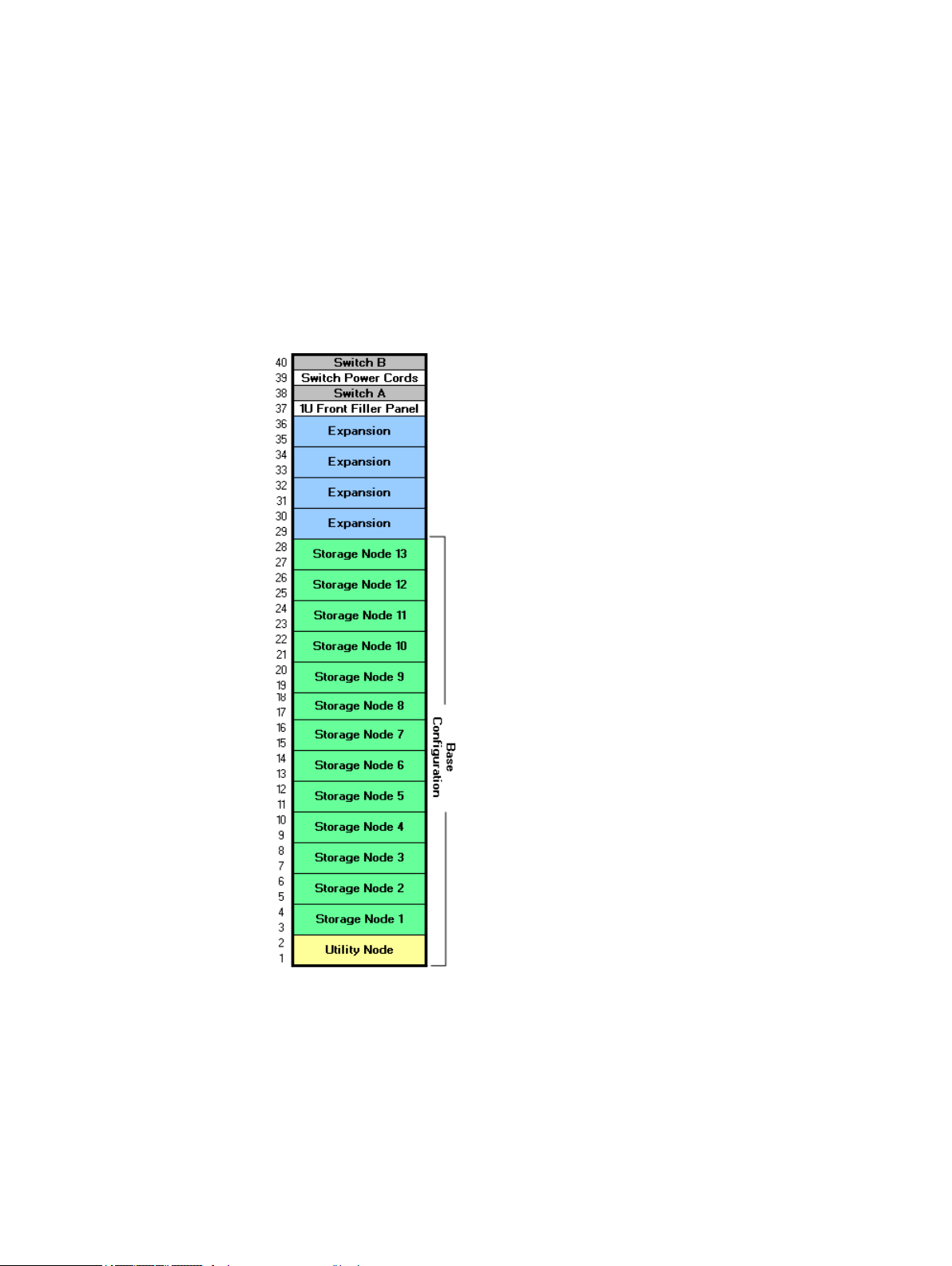
ADS multi-node server component locations
A 14-node example (1 utility node and 13 active storage nodes) of the initial
configuration of a standard ADS multi-node server is shown here. Initial configurations
range from 4 to 18 nodes (one utility node plus a maximum of 16 active storage nodes
and one optional spare storage node).
When performing remove and replace procedures in this document, use this diagram to
determine component locations.
Figure 1 Multi-Node Layout
Because previous component replacement might have changed the arrangement of
nodes in the rack, always use the instructions in this guide to verify the location of a
defective component before continuing. Since a spare can replace any defective storage
node, and because a replacement node can become the new spare, the location of any
specific storage node can vary over time.
Each rack configuration has 40U capacity. For Gen4T, the utility node takes up a 2U
increment. All storage nodes take up 2U increments. The utility node is at the bottom of a
multi-node configuration, with active storage nodes and an optional spare storage node
stacked above it. Additional nodes can be added in expansion slots starting with the
lowest available slot.
10 EMC Avamar Data Store Gen4T Customer Service Guide
Page 11

Switches A and B at the top are ADS internal network switches. Switch A is the bottom
one.
The minimum ADS multi-node configuration is one utility node and three storage nodes.
The maximum is 1 utility node, 16 active storage nodes, and an optional spare storage
node.
Utility node
In scalable multi-node Avamar servers, a single utility node provides essential internal
services for the server (for example, administrator server, replication, external
authentication, network time protocol [NTP], and Web access). Because utility nodes are
dedicated to running these essential services, they cannot be used to store backups.
Single node Avamar servers
Single node servers are individual Avamar storage nodes configured to perform both
utility node and storage node functions. The information in the following chapters
accounts for both single node and multi-node CRU servicing.
NDMP accelerator node
Replacing Avamar Data Store Components
An Avamar NDMP accelerator (accelerator node) is a dedicated single-node Avamar client
that, when used as part of an Avamar system, provides a complete backup and recovery
solution for supported EMC Isilon, VNX, VNXe, and Celerra systems, and NetApp filers by
using Network Data Management Protocol (NDMP) to communicate with these storage
devices. It is not part of the ADS server.
Recommended tools and supplies
To perform the CRU replacement procedures in the chapters that follow, no tools or
additional supplies are required.
The PuTTY SSH client will be used throughout the CRU replacement procedures.
Node components
Before handling ADS Gen4T equipment, first familiarize yourself with the Gen4T node
types and component locations for your specific hardware. See the figures and tables
that follow for details.
Figure 2 Front View
Utility node 11
Page 12

Replacing Avamar Data Store Components
Table 3 Front panel components
Feature Description
Hard drives Hot swappable 3.5” hard drives:
Figure 3 Rear View
l
Utility node - Two in the 0 and 1 drive locations. All others are
blank.
l
M600 node - Four in the 0 through 3 drive locations. All others
are blank.
l
M1200 node - Six in the 0 through 5 drive locations. All others
are blank.
l
M2400 node - 12 in the 0 through 11 drive locations.
l
Avamar Business Edition (S2400) node - Eight in the 0 through 7
drive locations. All others are blank.
l
Accelerator node - Two in the 0 and 1 drive locations. All others
are blank.
Table 4 Rear panel components
Feature Description
Service tag A pull-out label with the serial number and other system information.
Power supply #0 1100W power supply.
Power supply #1 1100W power supply.
SLIC bays Hosts for network interfaces. Each 10GBase-T or 10GbE Twinax/
SSD bays Host for SSD storage devices. Only the S2400 and M2400 contain an
RMC shared port The remote management port that is used to share remote
12 EMC Avamar Data Store Gen4T Customer Service Guide
Optical SLIC hosts four network ports. All unoccupied bays contain
fillers.
SSD. All other models contain two fillers.
management traffic and backup traffic.
Page 13

Replacing Avamar Data Store Components
Table 4 Rear panel components (continued)
Feature Description
RMC dedicated port The remote management port that is used when remote management
traffic is not shared.
USB port Connects a USB device.
Serial port Connects a device via RS-232 to provide direct access to the console.
Gen4T hardware does not support direct monitor and keyboard
connectivity.
Do Not Unplug LED Indicates that the node should not be powered off or unplugged.
Service LED Indicates that the node requires some type of service.
Power LED Indicates that the node is powered on.
Reset Reset the node by using the end of a paper clip to press the Reset
button. Use this button only if directed to do so by qualified support
personnel.
General information for removing and installing CRUs
This section describes precautions you must take and general procedures you must
follow when removing, installing, or storing CRUs. The procedures in this section apply to
CRU handling during general replacement.
Avoiding Electrostatic Discharge (ESD) damage
When replacing or installing CRUs, you can inadvertently damage the sensitive electronic
circuits in the equipment by simply touching them. Electrostatic charge that has
accumulated on your body discharges through the circuits. If the air in the work area is
very dry, running a humidifier in the work area helps decrease the risk of ESD damage.
You must use the following procedures to prevent damage to the equipment, so read the
following instructions carefully.
l
Provide enough room to work on the equipment. Clear the work site of any
unnecessary materials or materials that naturally build up electrostatic charge, such
as foam packaging, foam cups, cellophane wrappers, and similar items.
l
Do not remove replacement or upgrade CRUs from their antistatic packaging until you
are ready to install them.
l
Gather the ESD kit and all other materials you will need before you service a
component. Once servicing begins, you should avoid moving away from the work
site; otherwise, you may build up an electrostatic charge.
l
Use the ESD kit when handling any CRU.
If an emergency arises and the ESD kit is not available, follow the procedures in the
section Emergency procedures (without an ESD kit) on page 14.
l
Use the ESD wristband that is supplied with your system.
To use it, attach the clip of the ESD wristband (strap) to any bare (unpainted) metal
on the cabinet enclosure; then secure the wristband around your wrist with the metal
button against your skin.
General information for removing and installing CRUs 13
Page 14

Note
Replacing Avamar Data Store Components
Emergency procedures (without an ESD kit)
In an emergency, when an ESD kit is not available, use the following procedures to
reduce the possibility of an electrostatic discharge by ensuring that your body and the
subassembly are at the same electrostatic potential.
These procedures are not a substitute for the use of an ESD kit. You should follow them
only in the event of an emergency.
l
Before touching any CRU, touch a bare (unpainted) metal surface of the enclosure.
l
Before removing any CRU from its antistatic bag, place one hand firmly on a bare
metal surface of the enclosure, and at the same time, pick up the CRU while it is still
sealed in the antistatic bag. Once you have done this, do not move around the room
or contact other furnishings, personnel, or surfaces until you have installed the CRU.
l
When you remove a CRU from the antistatic bag, avoid touching any electronic
components and circuits on it.
l
If you must move around the room or touch other surfaces before installing a CRU,
first place the CRU back in the antistatic bag. When you are ready again to install the
CRU, repeat these procedures.
Removing, installing, or storing CRUs
Use the following precautions when you remove, handle, or store CRUs:
l
Do not remove a CRU from the cabinet until you have the replacement available.
l
Handle a CRU only when wearing a properly attached ESD wristband:
Attach the clip of the ESD wristband to the ESD bracket or to a bare metal portion of
the CRU's enclosure.
Secure the wristband around your wrist with the metal button against your skin.
l
Handle a CRU gently. A sudden jar, drop, or vibration can permanently damage some
CRUs.
l
The weight of some CRUs is not evenly distributed. To prevent personal injury or
equipment damage when removing, installing, or handling theses CRUs, use both
hands and provide extra support at the heavy end of the CRU.
l
Never use excessive force to remove or install a CRU.
l
Store a CRU in the antistatic bag and the specially designed shipping container in
which you received it. Use this special shipping container when you need to return
the CRU.
l
If you need to store a CRU for a short time, make sure the temperature of the location
where you store CRU is within the limits specified by the CRU's Technical
Specifications.
Identifying the node with the defective CRU
The following describes how to identify the node that requires service.
Procedure
1. For each node, determine if the amber system service LED on the front bezel is
illuminated.
14 EMC Avamar Data Store Gen4T Customer Service Guide
Page 15

Note
Replacing Avamar Data Store Components
Some malfunctions may not cause the system service LED to illuminate.
Figure 4 Front Bezel LEDs
2. From the back of the cabinet, locate the service tag on the lower right side of each
chassis. The service tag is located just below the power supplies.
Pull the service tag out to reveal the serial number.
Figure 5 Service Tag Location
3. Determine if the service LED on the rear I/O panel is illuminated.
Identifying the node with the defective CRU 15
Page 16

Note
Replacing Avamar Data Store Components
Some malfunctions may not cause the service LED to illuminate.
Figure 6 Service LED
16 EMC Avamar Data Store Gen4T Customer Service Guide
Page 17

CHAPTER 2
Replacing a Hard Drive
This chapter describes how to replace a hot-pluggable 3.5-inch hard drive (EMC part
number 005051760) in an ADS Gen4T node.
Topics in this chapter include:
l
Overview............................................................................................................... 18
l
Locating the defective hard drive...........................................................................18
l
Replacing a hard drive...........................................................................................19
l
Confirming the RAID rebuild.................................................................................. 22
l
Returning the defective CRU.................................................................................. 23
Replacing a Hard Drive 17
Page 18

Note
Note
Replacing a Hard Drive
Overview
The following instructions call for hard drives in removable carriers to be removed from
and replaced in a backplane in the node's chassis.
Use only hard drives that are tested and approved for use with ADS Gen4T nodes.
Replacement hard drives arrive blank at the customer site and they require no manual
configuration. RAID software automatically rebuilds the hard drive image when the new
one is detected.
Before performing the following procedure, obtain the following information about the
Avamar system or node, as applicable:
l
The fully qualified domain name of the Avamar server
l
The service tag or serial number of the Avamar node with the defective hard drive
l
The IP address of the Avamar node with the defective hard drive
l
The physical hard disk ID for the defective hard drive
If you do not have this information, contact EMC Technical Support before continuing.
To avoid inadvertently damaging sensitive electronic circuits in the equipment, ensure
that you follow precautions and general safety procedures when removing, installing, or
storing CRUs. See General information for removing and installing CRUs on page 13.
Locating the defective hard drive
After locating the node requiring service, verify which hard drive must be replaced by
performing the following:
Procedure
1. Using PuTTY, the IP address of the node, and a computer on the customer network
with access to the node, establish an SSH session to the node.
2. Log in as the admin user.
3. Change to the root user by typing:
su -
4. Check the hard drive to be replaced by typing on a single command line:
avsysreport pdisk | egrep 'Status|Slot Number|Enclosure Device'
Output similar to the following is displayed:
Slot Number : 0
Enclosure Device ID : 9
Status : Ok
Slot Number : 1
Enclosure Device ID : 9
Status : Offline
Slot Number : 2
Enclosure Device ID : 9
Status : Ok
Slot Number : 3
Enclosure Device ID : 9
18 EMC Avamar Data Store Gen4T Customer Service Guide
Page 19

Status : Ok
Note
Slot Number : 4
Enclosure Device ID : 9
Status : Ok
Slot Number : 5
Enclosure Device ID : 9
Status : Ok
In the output above, the hard drive whose status is not Ok is the one that must be
replaced. Take note of the Enclosure Device ID and Slot Number of the hard drive for
use in the remaining tasks.
If all hard drives are Ok, confirm the drive bay number for the drive to be replaced.
Contact EMC Customer Support for clarification.
Replacing a hard drive
After identifying the node and the defective hard drive, perform the following steps to
replace the hard drive.
Replacing a Hard Drive
Removing the hard drive
Procedure
1. From the front of the cabinet, press both tabs on the front of the bezel.
Figure 7 Bezel Removal
2. Pull the bezel away straight from the rack.
3. Using the physical disk ID provided by EMC Technical Support and verified above,
locate the defective hard drive.
Replacing a hard drive 19
Page 20

Replacing a Hard Drive
Figure 8 Front View
Use this physical location numbering sequence to identify the defective hard drive for
all node types. Typically, the hard drive LED turns solid amber when the hard drive has
failed.
4. Compare the label on the front of the defective and replacement hard drives to ensure
that you are replacing the defective hard drive with the same equipment.
Figure 9 Hard Drive Removal
5. On the carrier containing the defective hard drive, slide the orange latch to the right to
unlock the lever. Pull the lever open.
6. Pull the carrier forward and remove the carrier from the chassis.
20 EMC Avamar Data Store Gen4T Customer Service Guide
Page 21

Installing a hard drive
CAUTION
CAUTION
Replacing a Hard Drive
Before you begin
When installing a hard drive, ensure that any adjacent hard drives are fully installed.
Trying to insert and lock a hard drive carrier next to a partially installed carrier can
damage the adjacent carrier and render it unusable.
Never press on the middle of the bezel. Pressing on the middle of the bezel might result
in damage to the node.
Procedure
1. Ensure that the lever on the carrier containing the replacement hard drive is fully open
and that the orange latch is to the right.
Figure 10 Hard Drive Installation
2. Slide the carrier containing the replacement hard drive into the chassis.
3. When the lever begins to close by itself, push on the lever to lock it into place.
4. Press the bezel onto the latch brackets by pushing the ends of the bezel until it snaps
into place.
Installing a hard drive 21
Page 22

Replacing a Hard Drive
Figure 11 Bezel Installation
Confirming the RAID rebuild
After replacing a hard drive, the RAID system automatically begins rebuilding the data.
Typically, the hard drive LED begins blinking while the hard drive is rebuilding. Confirm
that the rebuild is successful by performing the following steps:
Procedure
1. List the tasks currently running on the disk controller by typing:
arcconf getstatus 1
Output similar to the following is displayed:
Controllers found: 1
Logical device Task:
Logical device : 0
Task ID : 32
Current operation : Rebuild
Status : In Progress
Priority : Low
Percentage complete : 1
Command completed successfully.
Note the ID number for the rebuild task.
2. Change the rebuild task to high priority by typing:
arcconf setpriority 1 <ID> HIGH
<ID>
where
is the task ID number noted in the previous step.
3. View the rebuild status by typing:
avsysreport pdisk pdisk=<Slot Number>
where <Slot Number> is the ID number that you noted previously. For example:
avsysreport pdisk pdisk=1
22 EMC Avamar Data Store Gen4T Customer Service Guide
Page 23

Output similar to the following is displayed:
Note
Physical Disk ID : 1
Status : Ok
State : Rebuilding
Write Caching : Disabled
Media Error Count : 0
Firmware Revision : GS18
Serial Number : R16E 0000R539RP2Z
Device Speed : 6.0 Gb/s
Media Type : Hard Disk Device
Slot Number : 1
Product ID : ST2000NXCLAR2000
Other Error Count : 0
Formatted Size : 1.816 TB
Raw Size : 1.819 TB
Native Command Queueing : Enabled
Link Speed : 12.0 Gb/s
Failure Predicted : No
Enclosure Device ID : 0
Device ID : 9
Rebuild Progress : 1%
Vendor : SEAGATE
Disk Type : SAS
SAS Address : 5000C500837E671C
Predictive Failure Count : 0
Replacing a Hard Drive
The State for the hard drive that you replaced should be Rebuilding.
If the State of the replacement disk drive is not Rebuilding, the node has more
serious problems than just a defective hard drive. In this case, contact EMC Customer
Support.
4. Note the values for Write Caching, Rebuild Progress (a percentage), and State
(Rebuilding).
The RAID rebuild process can take hours to complete. It is finished when State is
Online, Write Caching is Disabled, and Rebuild Progress is Not Applicable.
5. Close the terminal window.
Returning the defective CRU
Package the defective CRU and return it to the factory. Use the box and packing from the
replacement CRU.
Returning the defective CRU 23
Page 24

Replacing a Hard Drive
24 EMC Avamar Data Store Gen4T Customer Service Guide
Page 25

CHAPTER 3
Replacing a Power Supply
This chapter describes how to replace a power supply (EMC part number
071-000-608-01) in an ADS Gen4T node.
Topics in this chapter include:
l
Overview............................................................................................................... 26
l
Locating the defective power supply......................................................................26
l
Replacing a power supply......................................................................................28
l
Verifying the replacement power supply................................................................ 30
l
Returning the defective CRU.................................................................................. 31
Replacing a Power Supply 25
Page 26

Note
Note
CAUTION
Replacing a Power Supply
Overview
This procedure describes how to replace a power supply in a Gen4T node.
Each ADS Gen4T node contains two power supplies, the second serving as a redundant,
hot-swappable power source. The node requires at least one power supply to operate
normally. The node is in redundant mode when two power supplies are installed and
both power supplies are connected to an AC power source. If either power supply fails, it
can be replaced during normal system operation.
When removing a power supply from a powered-on node, remove only one power supply
at a time.
Each power supply has three LEDs located on the rear face: AC Good, DC Good, and
Attention. These are the top, middle, and bottom LEDs, respectively.
During normal operation, the AC Good and DC Good LEDs illuminate green to indicate that
AC and DC power are within specification. If a power supply fails, the Attention LED
illuminates amber to indicate a fault.
Before performing the following procedure, obtain the following information about the
Avamar system or node, as applicable:
l
The fully qualified domain name of the Avamar server
l
The service tag or serial number of the Avamar node with the defective power supply
l
The IP address of the Avamar node with the defective power supply
If you do not have this information, contact EMC Technical Support before continuing.
To avoid inadvertently damaging sensitive electronic circuits in the equipment, ensure
that you follow precautions and general safety procedures when removing, installing, or
storing CRUs. See General information for removing and installing CRUs on page 13.
Locating the defective power supply
After locating the node requiring service, verify which power supply must be replaced by
performing the following:
Before you begin
Ensure that you correctly locate the defective power supply. Removing the wrong power
supply may abruptly power off the node and cause numerous problems.
Procedure
1. Using PuTTY, the IP address of the node, and a computer on the customer network
with access to the node, establish an SSH session to the node.
2. Log in as the admin user.
3. Change to the root user by typing:
su -
26 EMC Avamar Data Store Gen4T Customer Service Guide
Page 27

4. Verify the serial number by typing:
avsysreport chassis-info | grep "Serial"
Output similar to the following is displayed:
Serial Number : FLDCU151900012
5. Identify the defective power supply by typing:
avsysreport power-supply
Output similar to the following is displayed:
=== Power supply redundancy
Status : Critical
Redundancy State : Redundancy Lost
=== Power supplies
Power Supply ID : 0
Status : Ok
Location : PSA
Operational State : Inserted, Power Good
Firmware Revision : 4.27.0.1
Serial Number : FPSAB144300439
Power Supply ID : 1
Status : Critical
Location : PSB
Operational State : Inserted, Loss of Input
Firmware Revision : 4.27.0.1
Serial Number : FPSAB144300108
Replacing a Power Supply
One of the two power supplies should have a status that is not Ok or an operational
state that is not Inserted, Power Good. The status identifies which power
supply is not working (PS0 or PS1).
6. Inspect the rear of the power supply and determine if the Attention LED is illuminated.
Locating the defective power supply 27
Page 28

WARNING
Replacing a Power Supply
Figure 12 Power Supply Attention LEDs
Replacing a power supply
After identifying the ADS server, node, and defective power supply, perform the following
steps to replace the power supply.
Removing the power supply
Before you begin
Use caution when removing a defective power supply. It may be hot.
Procedure
1. Undo the retaining clip securing the power supply AC power cord, and unplug the
cord.
2. Push the orange latch to the left while pulling the defective power supply from the
chassis by its handle.
28 EMC Avamar Data Store Gen4T Customer Service Guide
Page 29

Figure 13 Power Supply Removal
Replacing a Power Supply
Installing the power supply
Procedure
1. Using the functioning power supply as a guide, orient the replacement power supply
in the SP module opening.
Installing the power supply 29
Page 30

Replacing a Power Supply
Figure 14 Power Supply Installation
2. Insert the replacement power supply into the SP module and push until it clicks into
place.
3. Connect the AC power cord to the replacement power supply and fasten the retaining
clip to secure the cord.
4. Allow several seconds for the node to recognize the power supply and determine
whether it is working properly. The AC Good and DC Good LEDs should illuminate
green. The Attention LED should stay off.
Verifying the replacement power supply
Procedure
1. Type the following command:
avsysreport power-supply
Output similar to the following is displayed:
=== Power supply redundancy
Status : Ok
Redundancy State : Fully Redundant
=== Power supplies
Power Supply ID : 0
Status : Ok
Location : PSA
Operational State : Inserted, Power Good
Firmware Revision : 4.20.0.1
Serial Number : FPSAG144900460
Power Supply ID : 1
Status : Ok
30 EMC Avamar Data Store Gen4T Customer Service Guide
Page 31

Location : PSB
Operational State : Inserted, Power Good
Firmware Revision : 4.20.0.1
Serial Number : FPSAG144900107
Both power supplies should have the status Ok and the operational state
Inserted, Power Good. The system redundancy state should be Fully
Redundant.
2. Close the terminal window.
Returning the defective CRU
Package the defective CRU and return it to the factory. Use the box and packing from the
replacement CRU.
Replacing a Power Supply
Returning the defective CRU 31
Page 32

Replacing a Power Supply
32 EMC Avamar Data Store Gen4T Customer Service Guide
 Loading...