

Page 1
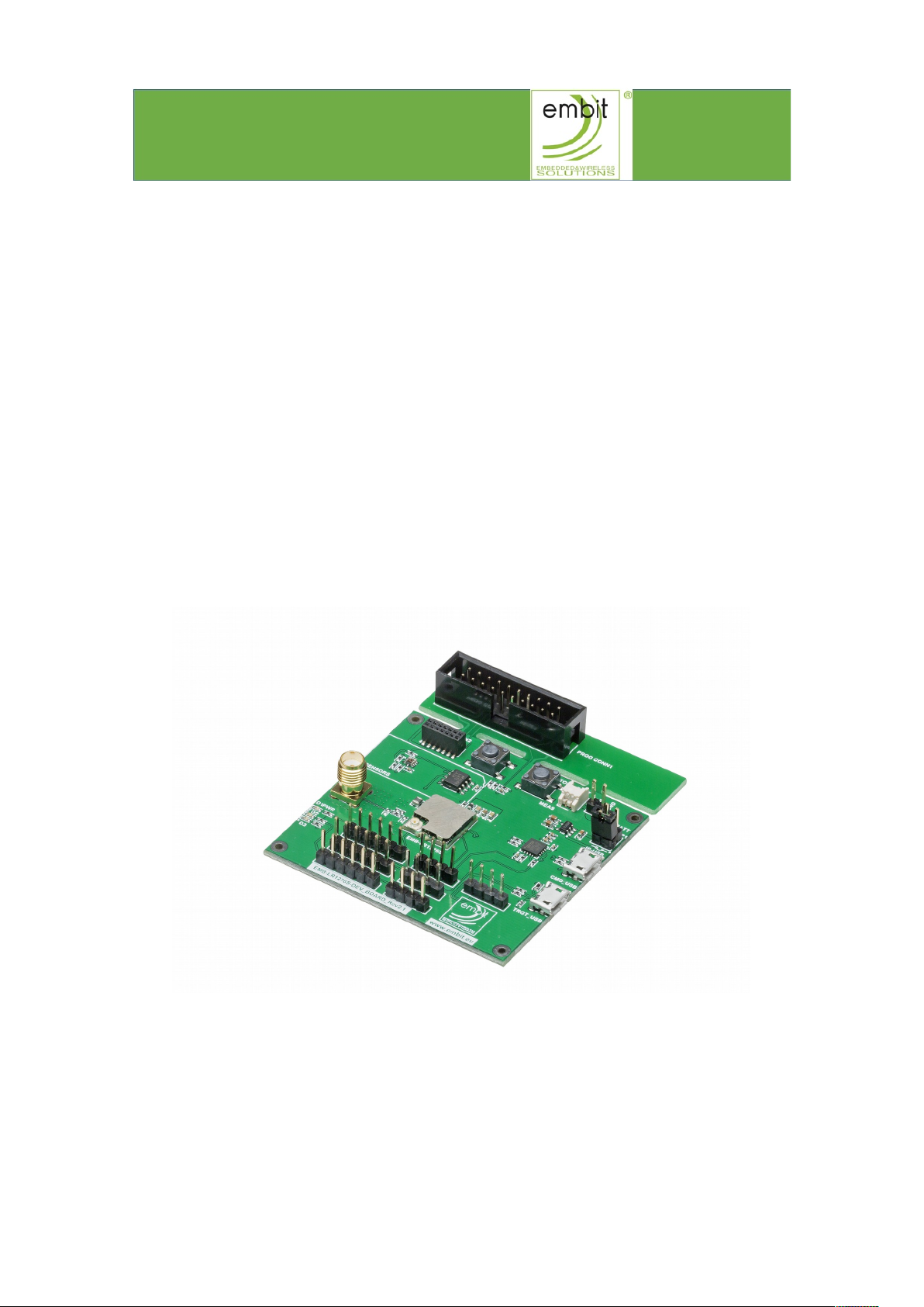
EMB-LR1276S Dev Board
EMB-LR1276S Dev Board
User Guide
User Guide
Rev. 2.1
Embit s.r.l.
Page 2
Document information
Versions & Revisions
Revision Date Author Comments
0.1 2019-02-18 Embit-MDD Initial release
1.0 2019-05-03 Embit-MDD Revision 1.0
2.0 2019-04-17 Embit-MDD Revision 2.0
2.1 2019-07-30 Embit-MDD Revision 2.1
Page 3

Index
1 Introduction...............................................................................................4
2 Description.................................................................................................4
2.1 Kit Overview...........................................................................................4
2.2 Hardware and Layout Configuration...........................................................5
3 Hardware User Guide.................................................................................6
3.1 EMB-LR1276S.........................................................................................6
3.2 Power Supply Connectors.........................................................................6
3.2.1 CMD_USB and TRGT_USB Connectors.....................................................................6
3.2.2 External Header (P3)........................................................................................ 7
3.2.3 External Battery (BATT).................................................................................... 8
3.3 Communication Interfaces........................................................................8
3.3.1 CN1-SERCOM-0............................................................................................... 9
3.3.2 CN2-SERCOM-2............................................................................................... 9
3.3.3 CN3-SERCOM-3.............................................................................................. 10
3.3.4 CN4........................................................................................................... 10
3.3.5 CN5........................................................................................................... 11
3.3.6 CN6........................................................................................................... 11
3.3.7 CN7-USB..................................................................................................... 12
3.4 Debugging Interface Connectors..............................................................12
3.5 Direct USB............................................................................................13
3.6 USB to UART connector..........................................................................13
3.7 On Board Sensors..................................................................................14
3.8 User Button..........................................................................................14
3.9 LEDs....................................................................................................15
3.10 RESET................................................................................................15
3.11 RF Antenna......................................................................................... 16
3.12 Board Revision History.........................................................................16
4 Firmware User Guide................................................................................17
4.1 Quick Start...........................................................................................17
4.2 EMB-LR1276S with EBI Commands..........................................................17
4.3 EMB-LR1276S as Micro Embedded...........................................................17
4.3.1 Download your own firmware............................................................................ 18
5 Create Your Own LoRaWAN® Network.....................................................19
6 References...............................................................................................19
7 Disclaimer of liability................................................................................20
7.1 Handling Precautions.............................................................................20
7.2 Limitations..........................................................................................20
7.3 Disclaimer of Liability............................................................................20
7.4 Trademarks.........................................................................................20
EMB-LR1276S Dev Board User Guide – Rev. 2.1 Page 3 of 20
Page 4
Introduction
1 Introduction
The Evaluation Board EMB-LR1276S Dev Board allows the user to exploit all
the capabilities of Embit’s module EMB-LR1276S [1], simplifying the
implementation of a prototype of a LoRa® communication system.
The board provides a simple connection to a computer or an external processor
via USB. For testing purpose, several pin headers are present to exploit the
capabilities of the module and ease the development of custom designs.
2 Description
2.1 Kit Overview
The EMB-LR1276S Dev Board is a hardware platform to evaluate the Embit’s
LoRa® module EMB-LR1276S.
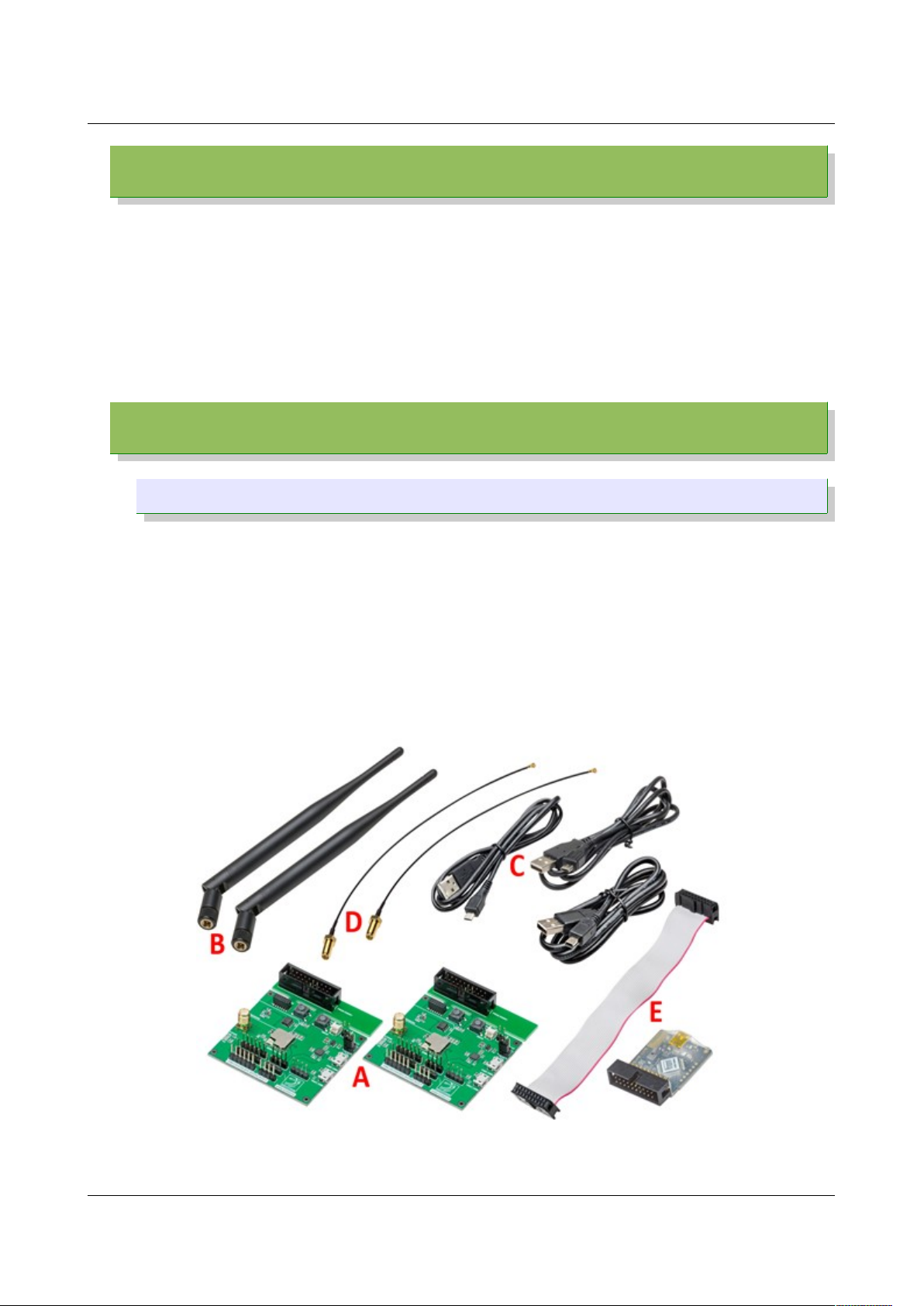
The kit (Figure 1) contains:
• 2 EMB-LR1276S Dev Board (A)
• 2 external 868 MHz antenna (B)
• 2 USB type A to Micro-B cable (C)
• 2 Pigtail connectors (D)
• 1 Segger J-Link Lite Programmer (with flat cable and mini USB cable) (E)
EMB-LR1276S Dev Board User Guide – Rev. 2.1 Page 4 of 20
Figure 1. EMB-LR1276S Evaluation Kit.
Page 5
Description
2.2 Hardware and Layout Configuration
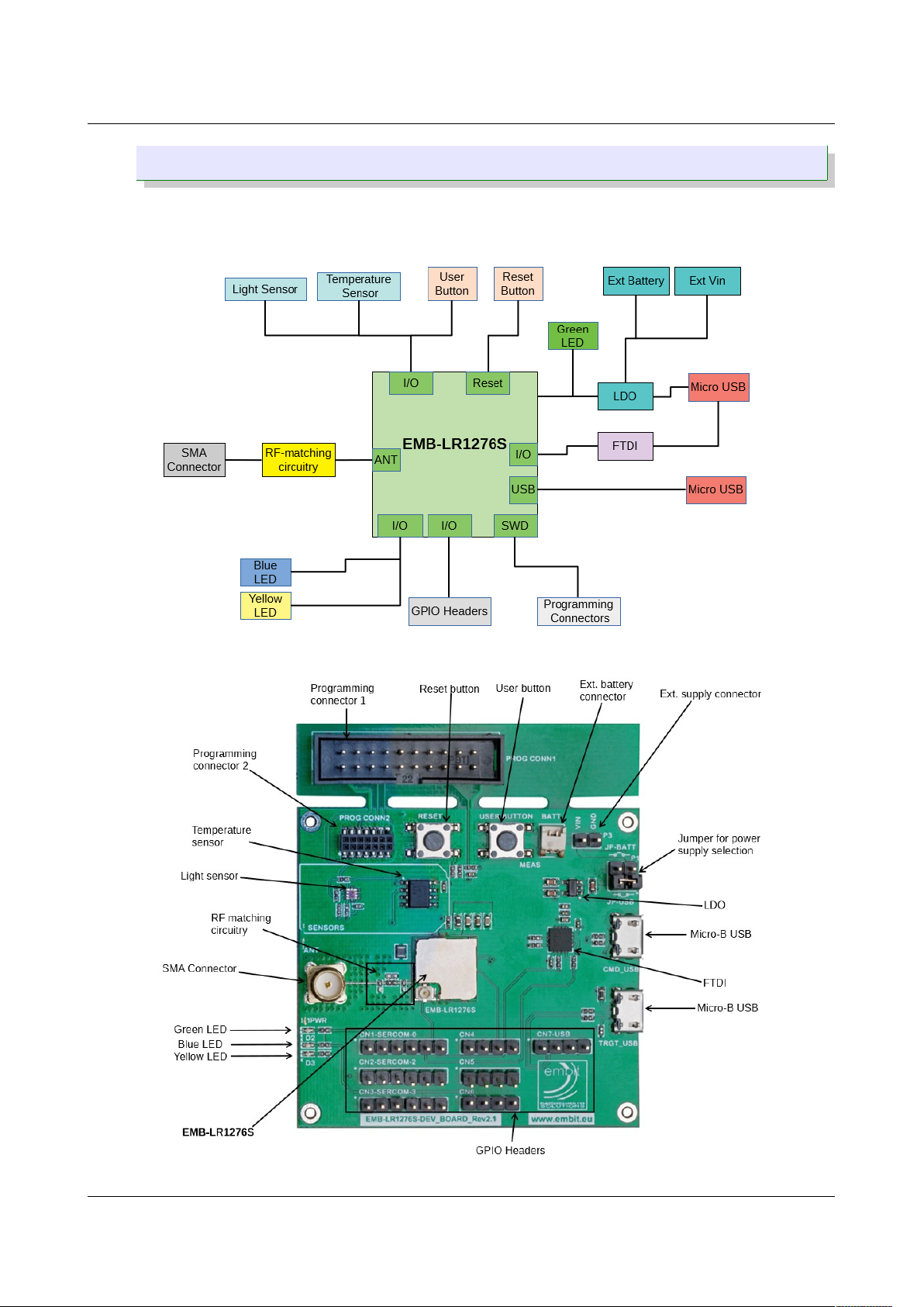
Figure 2 illustrates the connections between the EMB-LR1276S and the
peripherals (LEDs, push buttons, antenna, debugger, USB 2.0 Micro-B
connector, external battery) placed on the board as indicated in Figure 3.
EMB-LR1276S Dev Board User Guide – Rev. 2.1 Page 5 of 20
Figure 2. EMB-LR1276S Dev Board Rev 2.1 block diagram.
Figure 3. EMB-LR1276S Dev Board Rev 2.1 layout configuration.
Page 6
Hardware User Guide
3 Hardware User Guide
3.1 EMB-LR1276S
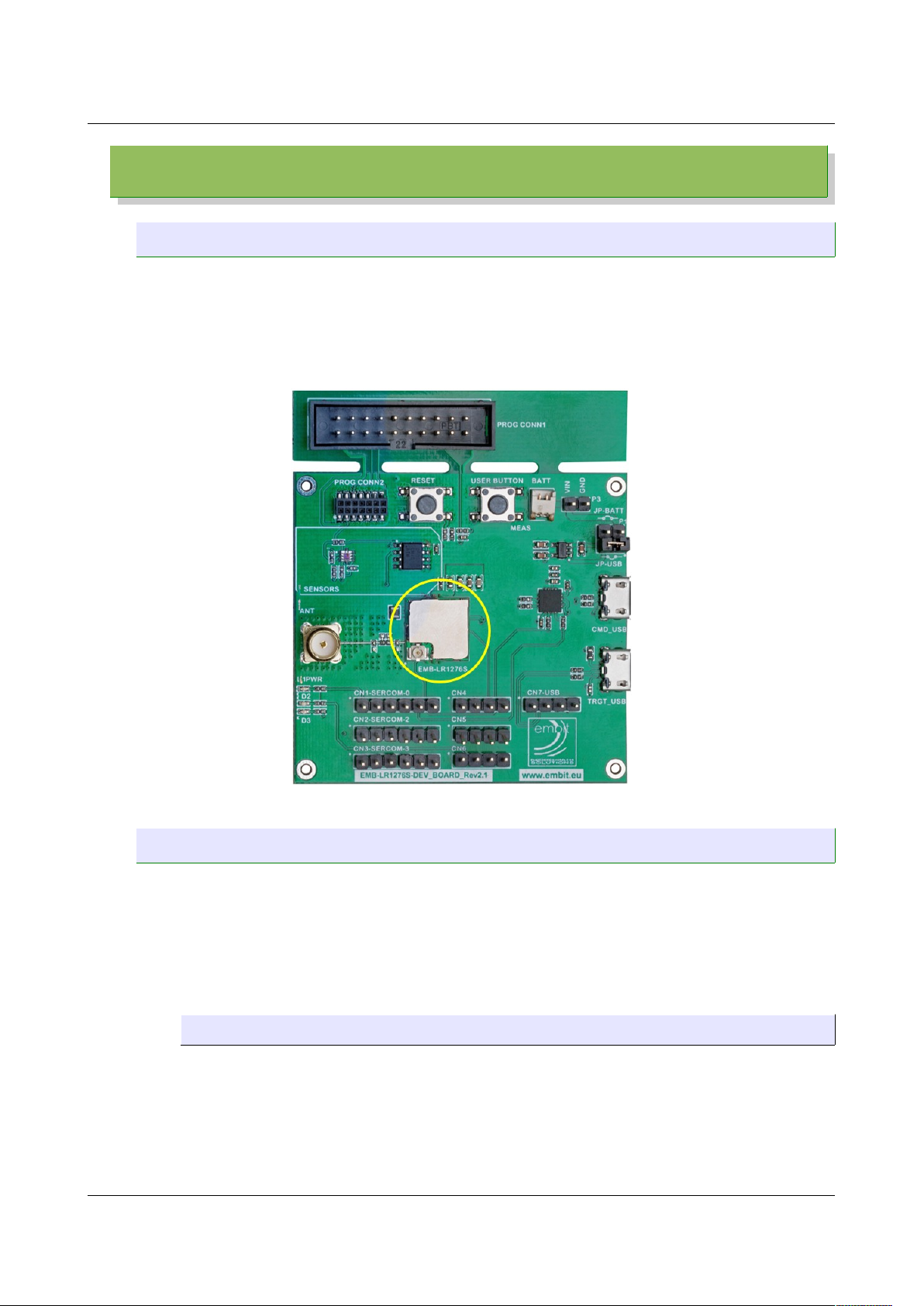
EMB-LR1276S (Figure 4) is the new sub-1GHz Embit’s wireless module that
supports the LoRaWAN® long range wireless protocol. It comes in a very small
form factor (11.5 x 11.5 mm) and integrates all the costumers needs to develop
complete and secure solutions.
Please refer to EMB-LR1276S datasheet [1] for detailed description.
3.2 Power Supply Connectors
The EMB-LR1276S Dev Board is designed to be powered in various ways:
• CMD_USB (Micro-B USB connector)
• TRGT_USB (Micro-B USB connector)
• External header (P3)
• External battery (BATT)
3.2.1 CMD_USB and TRGT_USB Connectors
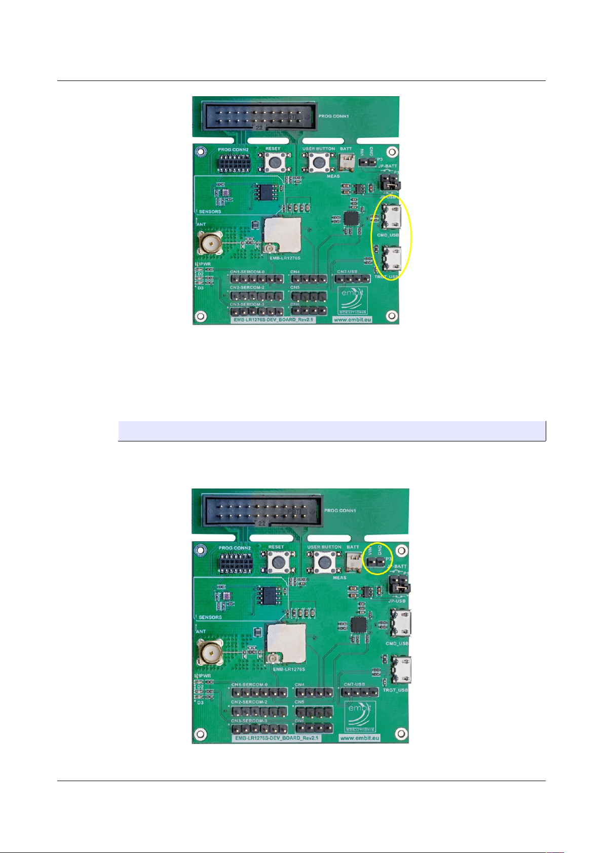
The board circuitry can be powered directly form a USB bus by plugging
the micro USB cable to one of the USB connector, CMD_USB or TRGT_USB
(Figure 5).
EMB-LR1276S Dev Board User Guide – Rev. 2.1 Page 6 of 20
Figure 4. EMB-LR1276S.
Page 7
Hardware User Guide
The power line on the board is regulated with a 3.3V dc linear regulator. Be
sure that the USB supply is capable to deliver enough current to supply the
module.
When the board is powered from one of the USB connector, the jumper
must be fitted on JP-USB of P1.
3.2.2 External Header (P3)
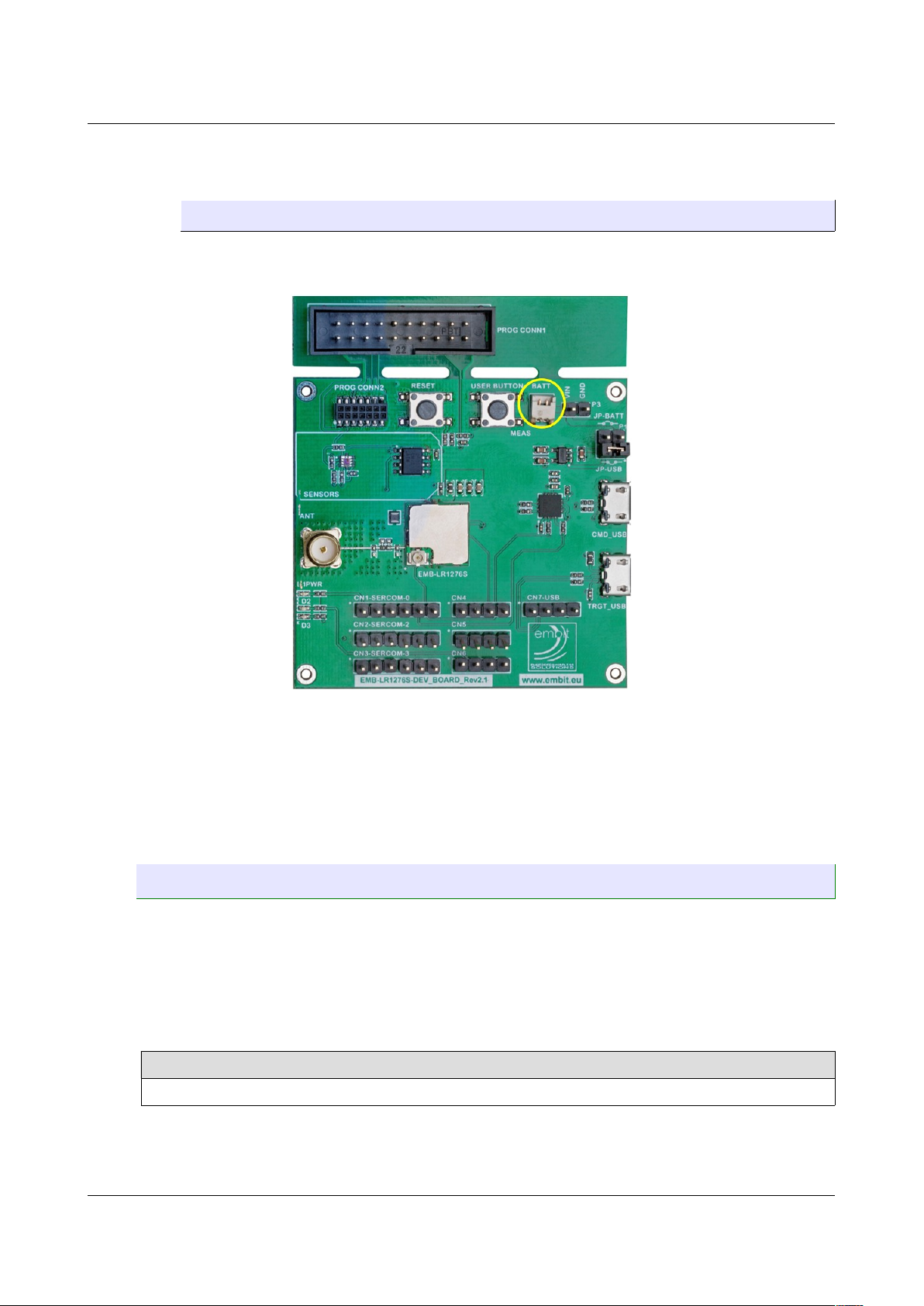
The board can be powered also using the Header P3 (Figure 6) with a
maximum of 6V. The pin on the right (as shown in the figure) is ground,
the pin on the left is Vin.
EMB-LR1276S Dev Board User Guide – Rev. 2.1 Page 7 of 20
Figure 5. CMD_USB and TRGT_USB connectors.
Figure 6. External header P3.
Page 8
Hardware User Guide
When the board is powered from this header, the jumper must be fitted on
JP-BATT of P1.
3.2.3 External Battery (BATT)
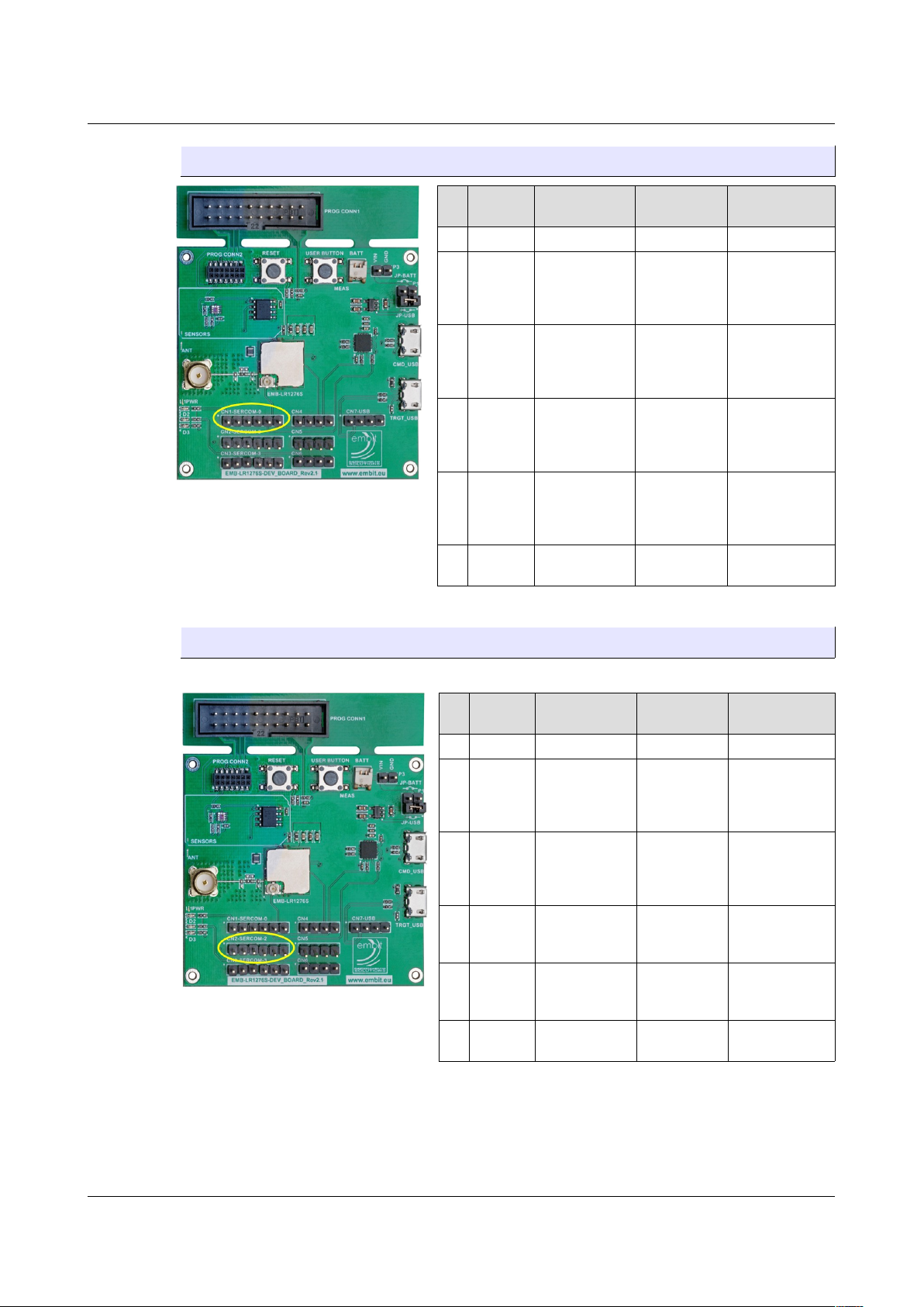
It is possible to plug an external battery to the BATT connector, 1.25mm
pitch (Figure 7).
Please be sure that the orientation of the battery is correct before to plug it
in to the connector. Ground pin is on the right, Vdd pin is on the left.
Battery voltage must not exceed 6V.
When the board is powered from this header, the jumper must be fitted on
JP-BATT of P1.
3.3 Communication Interfaces
The EMB-LR1276S Dev Board headers CN1 (Figure 8), CN2 (Figure 9), CN3
(Figure 10), CN4 (Figure 11), CN5 (Figure 12), CN6 (Figure 13), CN7 (Figure 14)
offer access to the I/O of the microcontroller in order to expand the board (e.g.,
by connecting sensors). The headers have a standard pitch of 2.54 mm.
Please note that not all the Sercom pins support I2C mode.
Pins Supporting I2C HS Mode
A5, A6, C3, G3, E4
EMB-LR1276S Dev Board User Guide – Rev. 2.1 Page 8 of 20
Figure 7. External battery connector.
Page 9
Hardware User Guide
3.3.1 CN1-SERCOM-0
Pin
Pin
Name
EMB-LR1276S
Pin
Type Functionality
1 Vdd - Power +3.3V
2 PA04 A1
Analog Input
or Digital I/O
AIN4
AIN0
SERCOM0[Pad0]
PA04
3 PA05 A2
Analog Input
or Digital I/O
AIN5
AIN1
SERCOM0[Pad1]
PA05
4 PA06 A3
Analog Input
or Digital I/O
AIN6
AIN2
SERCOM0[Pad2]
PA06
5 PA07 A4
Analog Input
or Digital I/O
AIN7
AIN3
SERCOM0[Pad3]
PA07
6 GND -
Power
(Ground)
GND
3.3.2 CN2-SERCOM-2
Pin
Pin
Name
EMB-LR1276S
Pin
Type Functionality
1 Vdd - Power +3.3V
2 PA08 A5
Analog Input
or Digital I/O
AIN16
SERCOM0[Pad0]
SERCOM2[Pad0]
PA08
3 PA09 A6
Analog Input
or Digital I/O
AIN17
SERCOM0[Pad1]
SERCOM2[Pad1]
PA09
4 PA14 C2 Digital I/O
SERCOM2[Pad2]
SERCOM4[Pad2]
PA14
5 PA15 C1 Digital I/O
SERCOM2[Pad3]
SERCOM4[Pad3]
PA15
6 GND -
Power
(Ground)
GND
EMB-LR1276S Dev Board User Guide – Rev. 2.1 Page 9 of 20
Figure 8. CN1 - Sercom0 header.
Figure 9. CN2 - Sercom2 header.
Page 10
Hardware User Guide
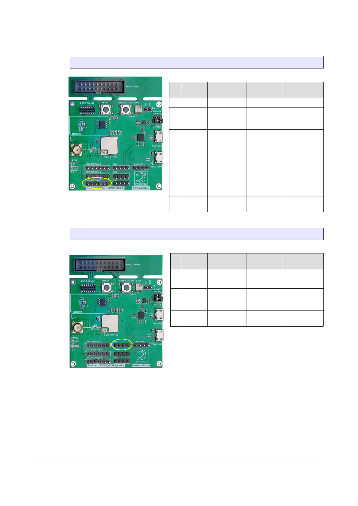
3.3.3 CN3-SERCOM-3
Pin
Pin
Name
EMB-LR1276S
Pin
Type Functionality
1 Vdd - Power +3.3V
2 PA22 G3 Digital I/O
SERCOM3[Pad0]
SERCOM5[Pad0]
PA22
3 PA23 E4
Analog Input
or Digital I/O
SERCOM3[Pad1]
SERCOM5[Pad1]
PA23
4 PA18 G2 Digital I/O
SERCOM1[Pad2]
SERCOM3[Pad2]
PA18
5 PA19 D1 Digital I/O
SERCOM1[Pad3]
SERCOM3[Pad3]
PA19
6 GND -
Power
(Ground)
GND
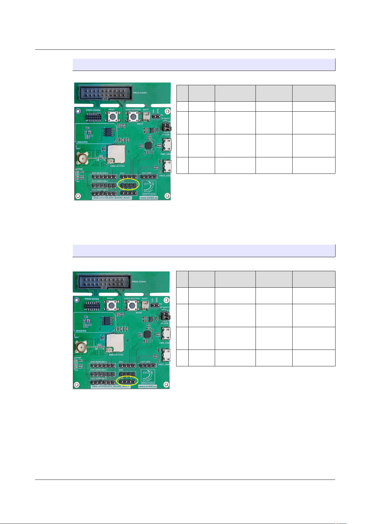
3.3.4 CN4
Pin
Pin
Name
EMB-LR1276S
Pin
Type Functionality
1 Vdd - Power +3.3V
2 - - - Not Connected
3 PB03 C6
Analog Input
or Digital I/O
AIN11
SERCOM5[Pad1]
PB03
4 GND -
Power
(Ground)
GND
EMB-LR1276S Dev Board User Guide – Rev. 2.1 Page 10 of 20
Figure 10. CN3 - Sercom3 header.
Figure 11. CN4 header.
Page 11
Hardware User Guide
3.3.5 CN5
Pin
Pin
Name
EMB-LR1276S
Pin
Type Functionality
1 Vdd - Power +3.3V
2
PA30_SW
CLK
D4
Digital I/O -
JTAG
SERCOM1[Pad2]
PA30
SWCLK
3
PA31_SW
DIO
D5
Digital I/O -
JTAG
SERCOM1[Pad3]
PA31
SWDIO
4 GND -
Power
(Ground)
GND
3.3.6 CN6
Pin
Pin
Name
EMB-LR1276S
Pin
Type Functionality
1 PB23 C5 Digital I/O
SERCOM5[Pad3]
PB23
2 PA13 C3 Digital I/O
SERCOM2[Pad1]
SEFCOM4[Pad1]
PA13
3 PB02 E6
Analog Input
or Digital I/O
AIN10
SERCOM5[Pad0]
PB02
4 GND -
Power
(Ground)
GND
EMB-LR1276S Dev Board User Guide – Rev. 2.1 Page 11 of 20
Figure 12. CN5 header.
Figure 13. CN6 header.
Page 12
Hardware User Guide
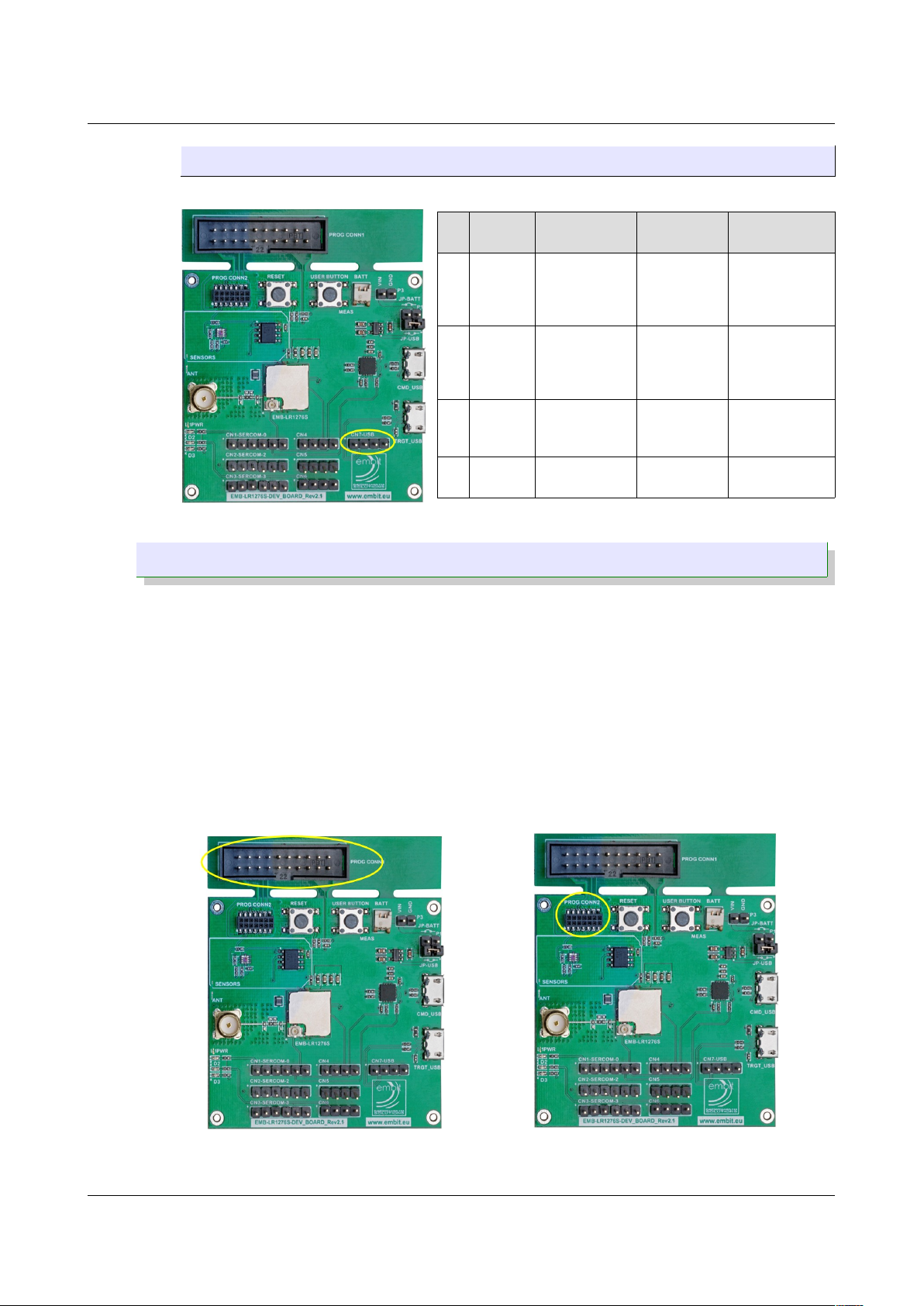
3.3.7 CN7-USB
Pin
Pin
Name
EMB-LR1276S
Pin
Type Functionality
1 PA24 D3 Digital I/O
SERCOM3[Pad2]
SERCOM5[Pad2]
USB_P
PA25
2 PA25 D2 Digital I/O
SERCOM3[Pad3]
SERCOM5[Pad3]
USB_N
PA24
3 PA15 C1 Digital I/O
SERCOM2[Pad3]
SERCOM4[Pad3]
PA15
4 GND -
Power
(Ground)
GND
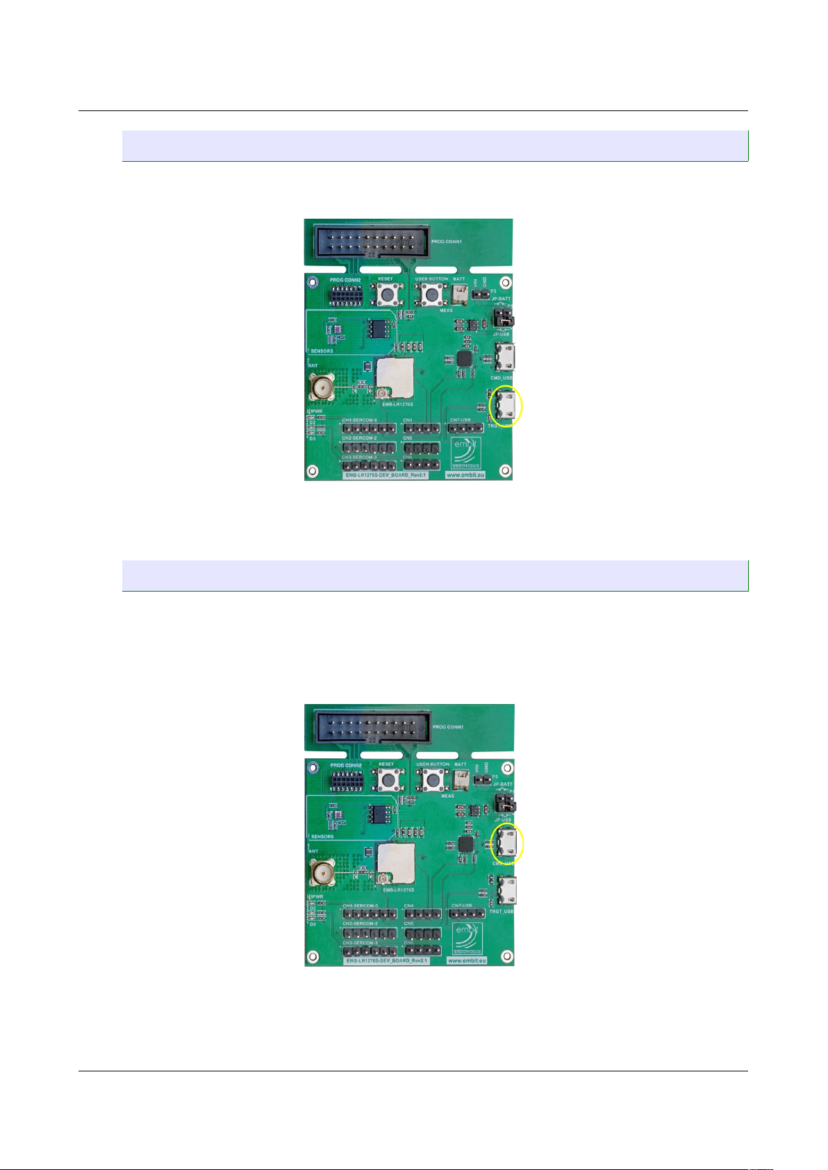
3.4 Debugging Interface Connectors
On the EMB-LR1276S Dev Board there are 2 types of connector for
programming the module. One of this is the standard JTAG connector 2x10
ways 2.54mm pitch male header (Figure 15a).
The second one has a custom pin-out specifically designed by Embit in order to
provide compatibility with every microcontroller used in Embit’s module. The
connector is a 2x7 ways 1.27mm pitch female header (Figure 15b). With the
adapter (Embit Multiprog), the debug hardware associated with the
microcontroller (ATSAMR34 in this case) can be connected to the board. In this
case the JTAG connector (PROG CONN1) is not needed and you can cut the part
of the PCB which includes this connect making the board smaller.
EMB-LR1276S Dev Board User Guide – Rev. 2.1 Page 12 of 20
Figure 14. CN7 - USB header.
Figure 15a. Debugging interface
connector JTAG.
Figure 15b. Debugging interface
connector for Embit Multiprog.
Page 13
Hardware User Guide
3.5 Direct USB
For USB applications, there is a directly connected USB port designated
TRGT_USB exposed as a Micro-B jack (Figure 16).
The USB lines are also routed to the header CN7-USB.
3.6 USB to UART connector
This connector, designated CMD_USB and exposed as a Micro-B jack (Figure
17), allows to access from a PC to the SERCOM0 (UART) of the module through
a virtual serial port over USB (FTDI USB-to-Serial UART converter). The UART to
USB conversion implements a full UART with hardware flow control (TX, RX,
RTS, CTS). Those UART lines are also routed to the header CN1-SERCOM-0.
EMB-LR1276S Dev Board User Guide – Rev. 2.1 Page 13 of 20
Figure 16. Direct USB connector.
Figure 17. USB-to-Uart connector.
Page 14
Hardware User Guide
3.7 On Board Sensors
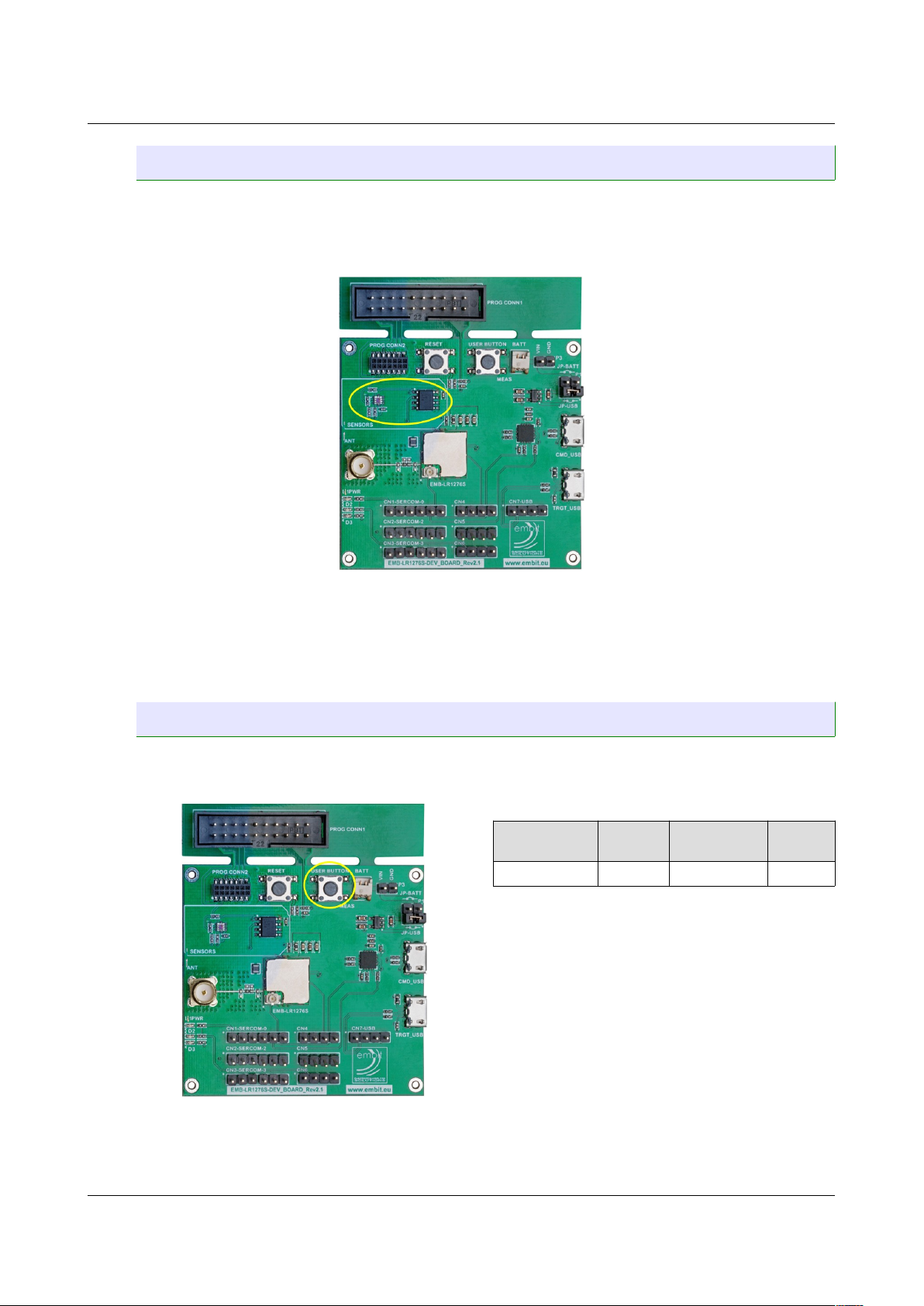
On the EMB-LR1276S Dev Board there are two sensors (Figure 18):
• Digital Temperature Sensor (LM75A by Texas Instruments)[3]
• Light Sensor (Si1141-A11 by Silicon Labs) [4]
Both sensors use the I2C bus and they are connected to A5 (SDA) and A6 (SCL)
pins of the EMB-LR1276S module.
SERCOM-2 is used to communicate with the sensors.
3.8 User Button
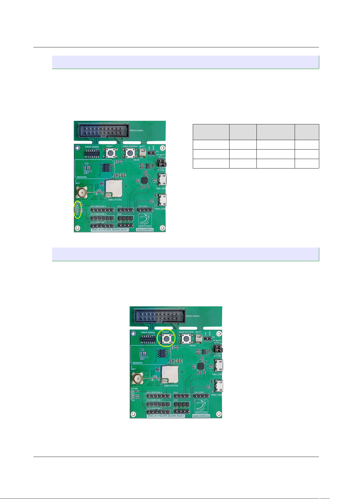
The User Button (Figure 19) is connected to one GPIO that can handle
interrupts. By pushing the button the corresponding line is grounded.
Button Signal
EMB-LR1276S
Pin
Type
User Button PB23 C5 Input
EMB-LR1276S Dev Board User Guide – Rev. 2.1 Page 14 of 20
Figure 18. Light and temperature sensors.
Figure 19. User button.
Page 15
Hardware User Guide
3.9 LEDs
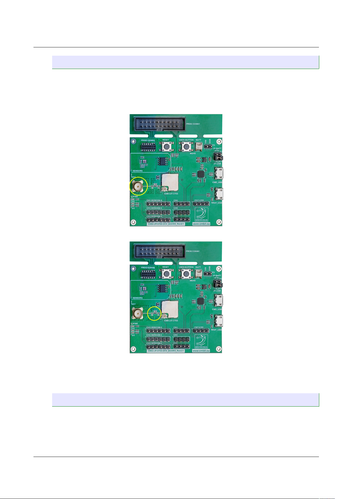
There are three LEDs on the board (Figure 20):
• D1: Green LED, it lights up when the board is powered
• D2: Blue LED, it is connected to a GPIO line
• D3: Yellow LED, it is connected to a GPIO line
LED Signal
EMB-LR1276S
Pin
Color
D1 3.3V - Green
D2 PA13 C3 Blue
D3 PB02 E6 Yellow
3.10 RESET
The hardware reset of the module can be forced by pressing the RESET button
(Figure 21). The switch signal is kept high by a 10kOhm pull-up resistor and the
signal is routed to the RESET# pin on the module (E5) through a 1kOhm series
resistor. By pressing the RESET button the RESET# line is grounded.
The programming interface is allowed to force the reset line too.
EMB-LR1276S Dev Board User Guide – Rev. 2.1 Page 15 of 20
Figure 20. LEDs.
Figure 21. Reset button.
Page 16
Hardware User Guide
3.11 RF Antenna
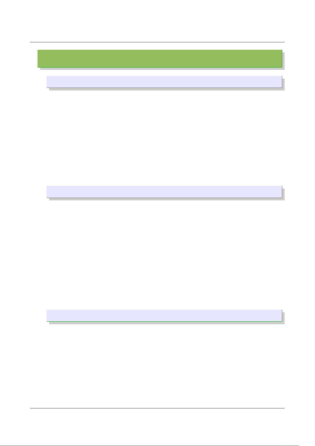
The antenna must be connected to the SMA connector ANT (Figure 22) for any
RF communication purpose. The path between the RF_OUT pad of the EMB-
LR1276S module and the SMA connector contains a matching circuitry (Figure
23) that can be mounted and adjusted by advanced users.
NOTE: If you want to use the u.FL connector on the EMB-LR1276S you
need to remove the components of the matching network.
3.12 Board Revision History
Rev 1.0: The first release for early costumers.
Rev 2.0: Final version of the board for internal use.
Rev 2.1: Final version of the board commercially available.
EMB-LR1276S Dev Board User Guide – Rev. 2.1 Page 16 of 20
Figure 22. SMA connector.
Figure 23. RF matching circuitry.
Page 17
Firmware User Guide
4 Firmware User Guide
4.1 Quick Start
A firmware is preloaded in the EMB-LR1276S Flash memory in factory. This
firmware allows the user to control the LoRa® module simply sending commands
on the USB interface.
Costumers can use the board in two ways:
1. As a modem: connecting the board to a host (a PC for example) through
the USB connector (CMD_USB) it is possible to send the EBI commands
[2] in order to join an existing LoRaWAN® network.
2. As micro embedded: developing their own firmware and discover all the
potentialities of the EMB-LR1276S using its peripherals. In this case EBI
commands are not needed.
4.2 EMB-LR1276S with EBI Commands
In order to start using Embit Evaluation Kit with EBI commands, you must
follow these steps:
• Place the jumper on JP-USB of P1.
• Mount the antenna on the SMA connector.
• Connect the USB cable included to the CMD_USB connector and plug it to
a PC. The green led D1 is lit.
• The board will be recognized as a Virtual Com Port.
• Now it is possible to communicate with the module using commands
described in the EBI-LoRa document [2].
To send commands you can use a terminal that allows you to send hex values.
Please refer to the document “Embit Binary Interface – LoRa specific
Documentation” [2].
4.3 EMB-LR1276S as Micro Embedded
In order to develop your own firmware and use all the features of the EMBLR1276S you need to:
• Download and install Atmel Studio 7.0 (minimum version)
• Update to the latest ASF version available
• Download and install JLink Software and Documentation Pack v6.42
(minimum version)
• Create your own firmware starting form the example project provided by
Embit
EMB-LR1276S Dev Board User Guide – Rev. 2.1 Page 17 of 20
Page 18
Firmware User Guide
• Download your project in to the EMB-LR1276S Flash memory (see
section 4.3.1)
4.3.1 Download your own firmware
To download your own firmware just plug the JTAG connector from the
JLink to the PROG CONN1 (or to the Multiprog and then plug the Multiprog
in to the PROG CONN2) of the EMB-LR1276S Dev Board.
Power up the board with the USB cable or a battery (please be sure that
the jumper is in the correct position on P1 header). The green led is lit.
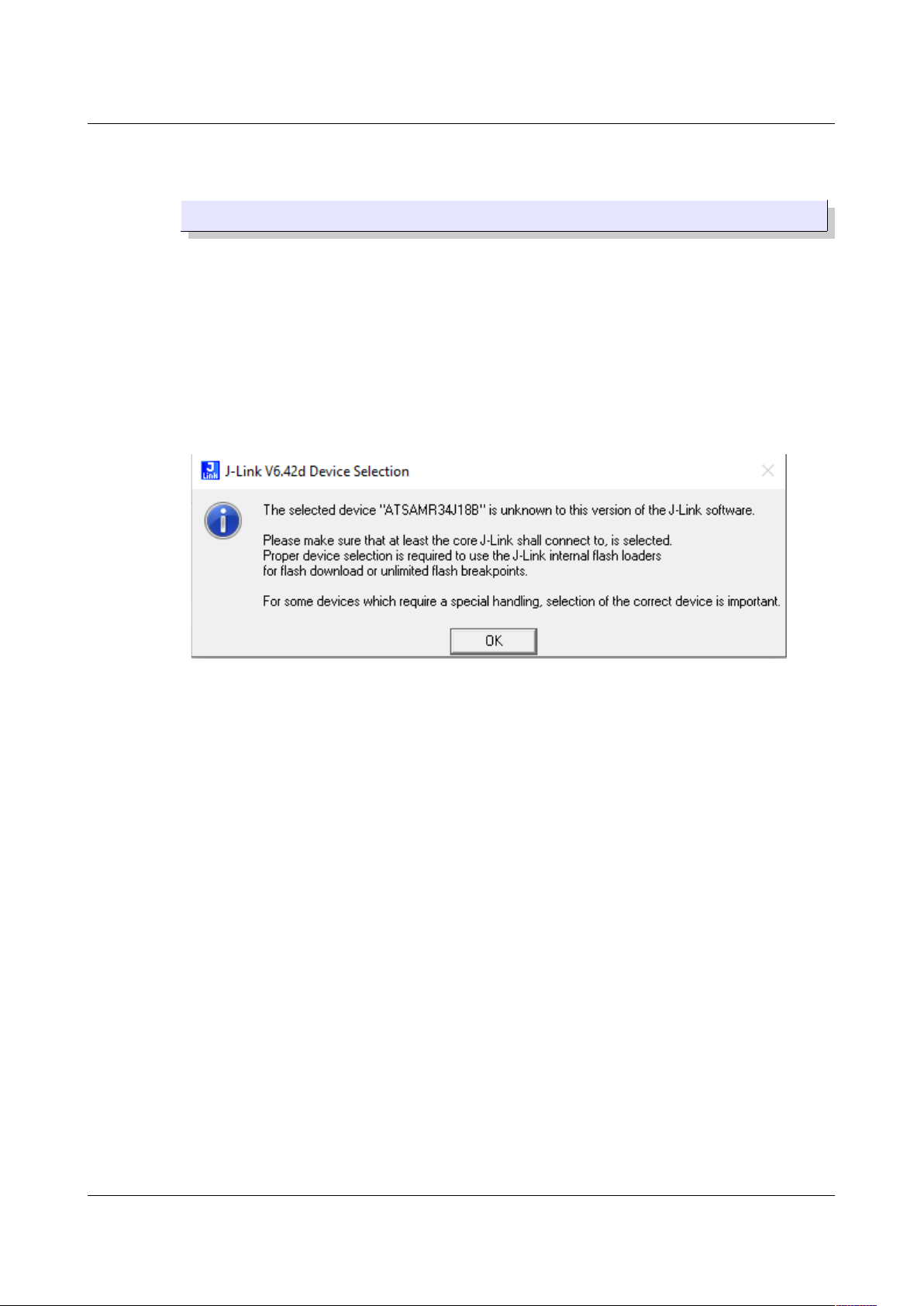
When you are going to download your firmware from Atmel Studio for the
first time into the EMB-LR1276S, you will receive a warning as in Figure
24.
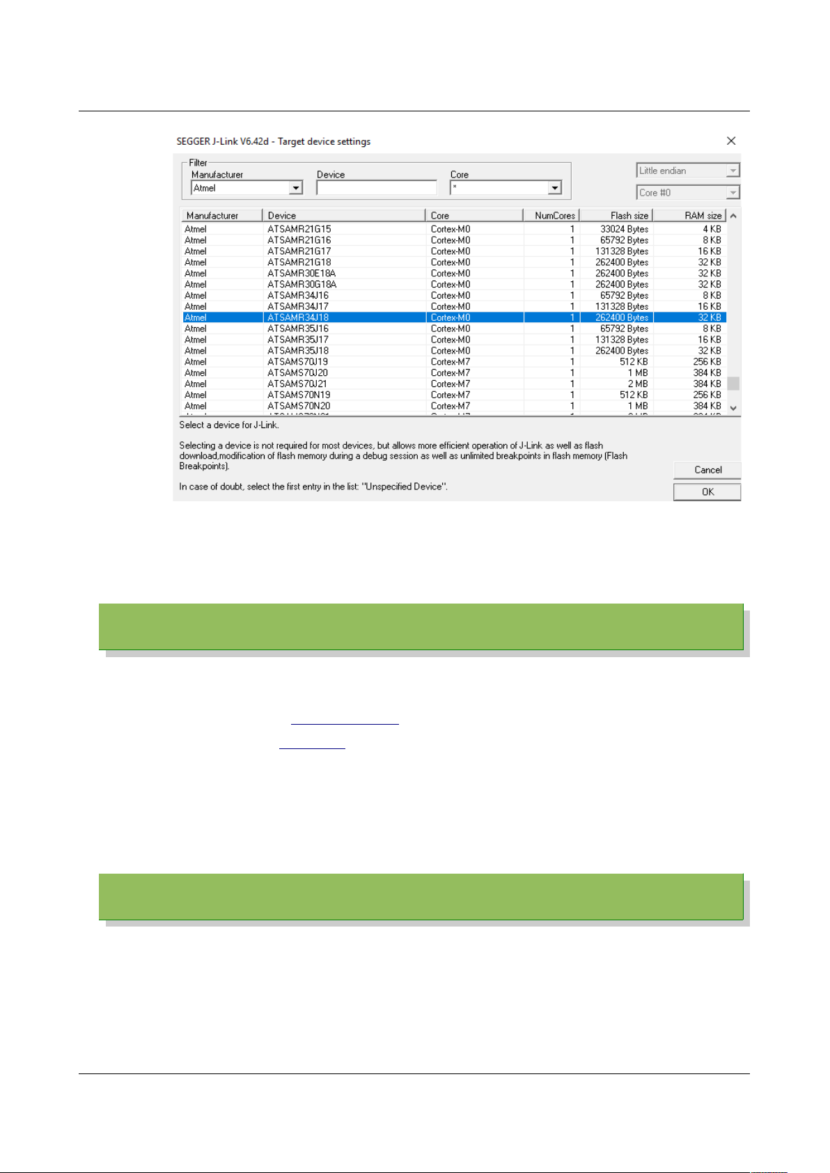
Click OK and a list of all the devices supported by the JLink will appear
(Figure 25). To facilitate the finding of the device, select “Atmel” from the
drop-down Manufacturer menu and scroll down the list until you will find
ATSAMR34J18. Select it and click OK.
EMB-LR1276S Dev Board User Guide – Rev. 2.1 Page 18 of 20
Figure 24. JLink warning.
Page 19
Firmware User Guide
The firmware will be downloaded into the Flash of the EMB-LR1276S.
5 Create Your Own LoRaWAN® Network
Embit gives to the users the possibility to create their own LoRaWAN® network.
To setup the network you will need:
• EMB-LR1276S (or EMB-LR1272E) as end-nodes
• EMB-Picocell (or GW1301) as gateway
• An account on a LoRaWAN
®
network server (A2A, TTN, etc.)
Please refer to documentation “EMB-GW1301-O Quick start Guide” [5] which
explain ho to configure your gateway with the LoRaWAN® network server chosen.
6 References
[1] Embit, EMB-LR1276S Datasheet Rev 1.0
[2] Embit, Embit Binary Interface – LoRa specific documentation v.1.0.1
[3] Texas Instruments, LM75A Datasheet
[4] Silicon Labs, Si1141/42/43 Datasheet
[5] Embit, EMB-GW1301-0 Quick Start Guide Rev 1.0
EMB-LR1276S Dev Board User Guide – Rev. 2.1 Page 19 of 20
Figure 25. JLink target devices list
Page 20
Disclaimer of liability
7 Disclaimer of liability
The user must read carefully all the documentation available before using the
product. In particular, care must be taken in order to comply with the regulations
(e.g., power limits, duty cycle limits, etc.).
7.1 Handling Precautions
This product is an ESD sensitive device. Handling precautions
should be carefully observed.
7.2 Limitations
Every operation involving a modification on the internal components of the
module will void the warranty.
7.3 Disclaimer of Liability
The information provided in this and other documents associated to the product
might contain technical inaccuracies as well as typing errors. Regulations might
also vary in time. Updates to these documents are performed periodically and
the information provided in these manuals might change without notice. The
user is required to ensure that the documentation is updated and the
information contained is valid. Embit reserves the right to change any of the
technical/functional specifications as well as to discontinue manufacture or
support of any of its products without any written announcement.
7.4 Trademarks
Embit is a registered trademark owned by Embit s.r.l.
All other trademarks, registered trademarks and product names are the sole
proprietary of their respective owners.
EMB-LR1276S Dev Board User Guide – Rev. 2.1 Page 20 of 20
 Loading...