

Page 1
EmbiPos
USER MANUAL
0536
1 1 A v e n u e d e l ’ h a r m o n i e
5 9 6 5 0 V i l l e n e u v e d ’ A s c q
F R A N C E
( + 3 3 ) 3 2 0 6 1 0 6 8 8 - w w w . e m b i s p h e r e . c o m
Page 2

2
Dear Customer,
Thank you for choosing this EMBISPHERE product. We hope that you will enjoy using it, will make
your encasement easier and that it will give you satisfaction for many years to come.
Once you unpack your EMBISPHERE product, we recommend that you take a few minutes to read the
following instructions.
Wishing you a pleasant experience with the EmbiPos.
The EMBISPHERE team
Page 3
3
SAFETY INFORMATION
Product Care
Your device is an electronic product that needs to be treated with care. Please follow the
instructions :
- Do not subject it to unnecessary shock or vibration.
- Keep your EmbiPos, cable and power supply away from water, rain and excessively humid
areas.
- Use only AC power supply and cable provided with your product.
- Do not open it up. There are no user-serviceable parts inside. Opening will void your
warranty.
- If your device is very cold or has been stored in a cold area, do not apply power to the
device until it has been allowed to come to room temperature.
- Unplug this apparatus from the AC power supply during lightning storms or when unused for
long periods of time
For your safety and to avoid any risk of personal injury please take few minutes to read these
operating instructions carefully before using the unit. Follow the safety instructions listed below.
Keep these operating instructions handy for future reference.
Page 4

4
SUMMARY
PRODUCT DESCRIPTION 5
1. GETTING STARTED 7
Unpacking the reader 7
Mounting and removing the reader 8
Connecting antennas 9
Connecting serial/RS232 cable 10
Connecting USB cable 10
GPIO interface 11
Powering the reader 11
Powering the reader 12
2. TECHNICAL SPECIFICATION 13
3. TROUBLESHOOTING 14
Page 5
5
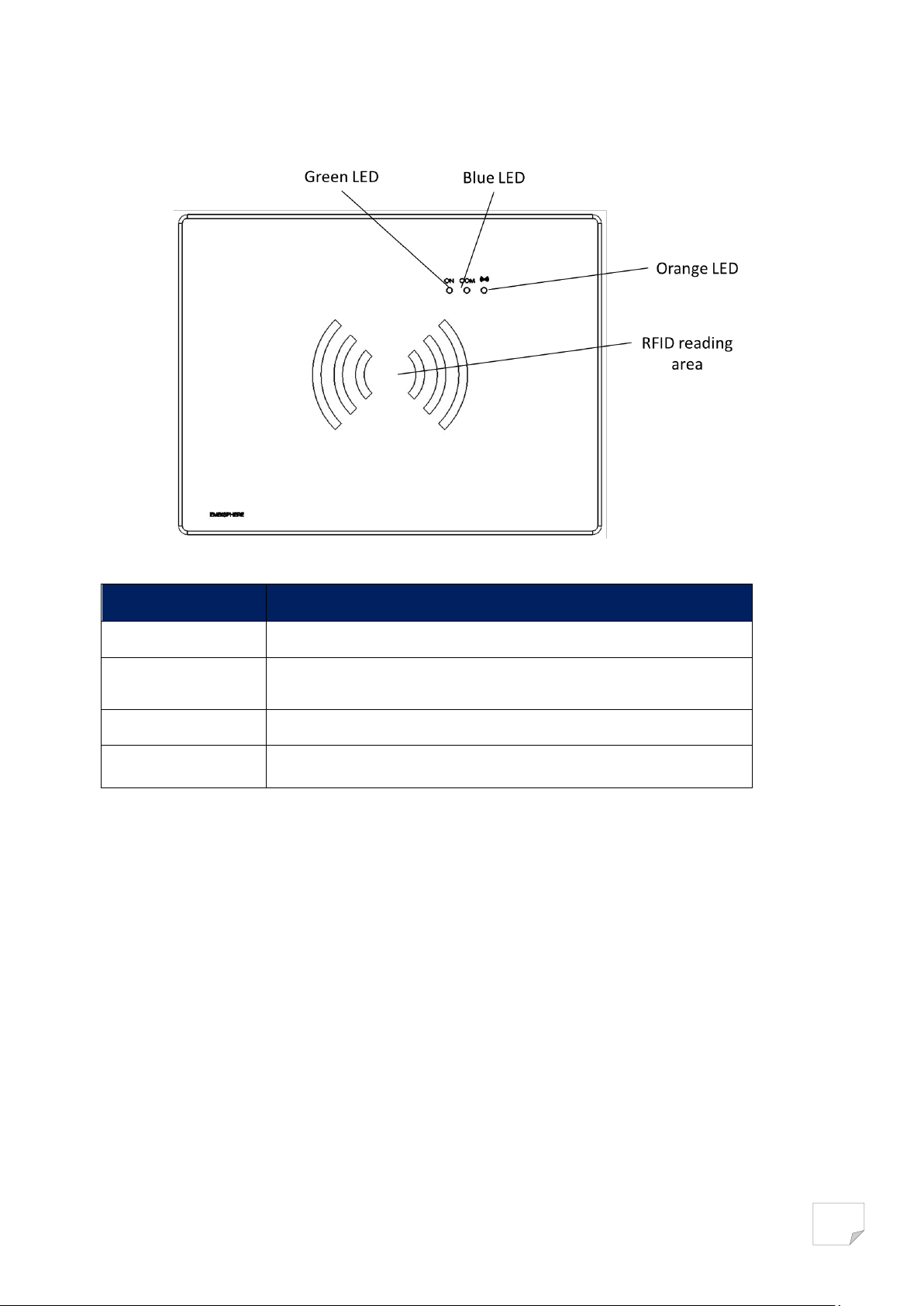
PRODUCT DESCRIPTION
Description
Fonction
Green LED
Power on/off indicator light
Blue LED
Link activity indicator light. Status of serial link to the host PC.
Orange LED
RFID activity indicator light
RFID reading area
Area where tag reading is optimal. Read distance depends on read
power settings
Figure 1: Top side product description
Page 6
6
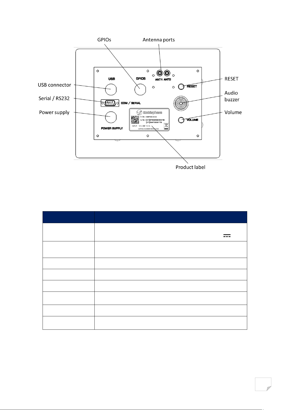
Description
Fonction
Power supply
DC connector connects to the EmbiPos approved power supply AC
adapter provided with your reader. Maximum power 12V 1,5A
Serial/RS232
RS232 serial link to host PC
USB connector
USB link to host PC
GPIOs
Insert the dedicated EmbiPos GPIOs cable
Antenna ports
2 SMA RF connection for 50 Ohms external antennas
RESET
To reset the reader, press and hold this yellow button for not less
than 1 seconds
Audio buzzer
Audio indicator for tags reading
Volume
Press volume button to change EmbiPos reader audio indicator
volume
Figure 2: Bottom side product description
Page 7
7
1. GETTING STARTED
Use only parts provided with the EmbiPos RFID reader or EMBISPHERE
approved/recommended parts.
Substituting other cables or parts can degrade system performance,
damage the reader, and/or void the warranty
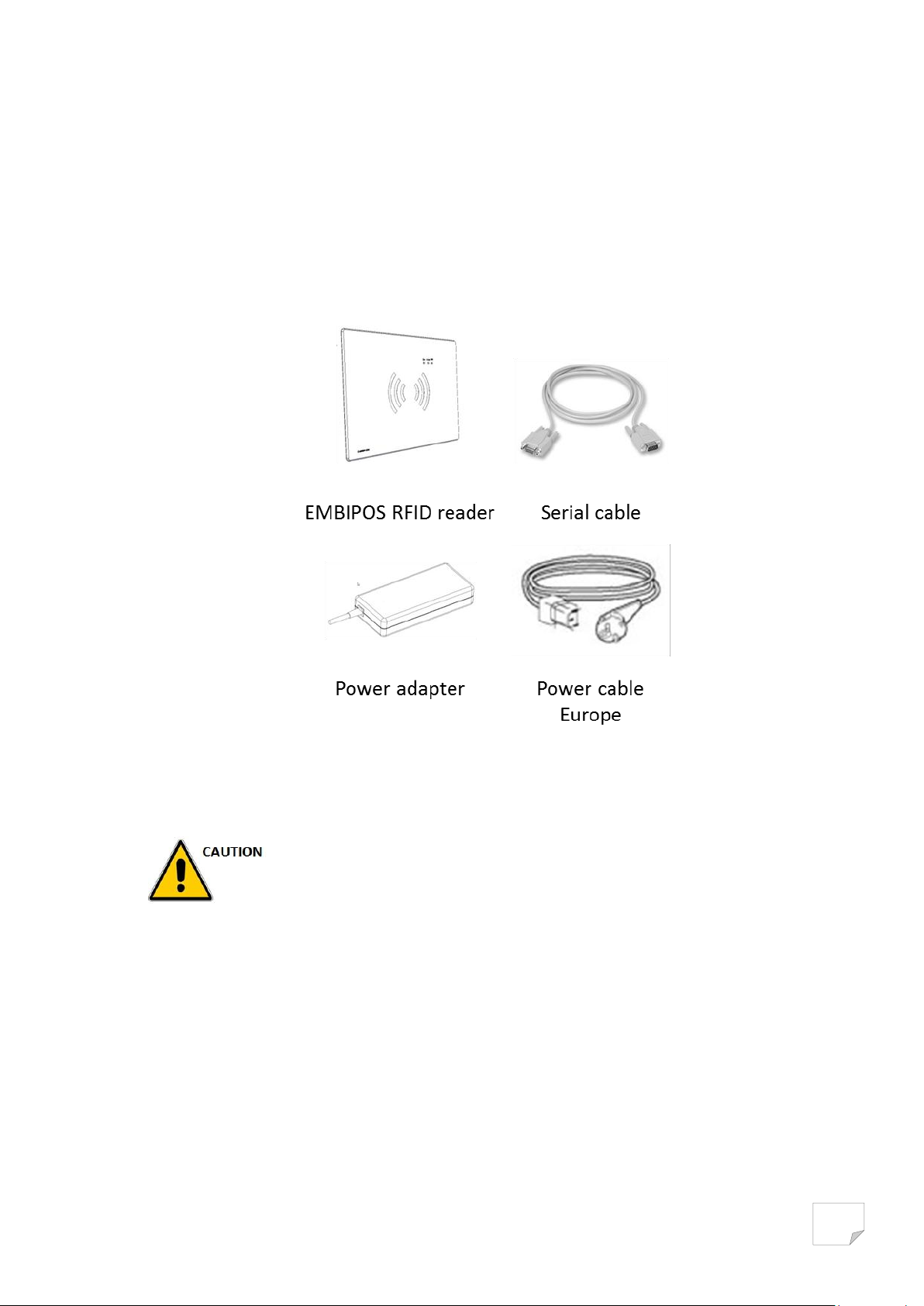
Unpacking the reader
Remove the reader from the shipping container and inspect it for damage. Keep the shipping
container, it is the approved shipping container and should be used if the reader needs to be
returned for servicing.
Figure 3: Packaging contents
Mounting and removing the reader
Preparing your desk
Before installing your EmbiPos please prepare your desk to host your reader
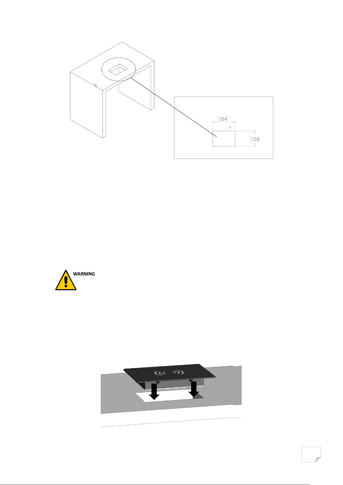
Drill your furniture to insert the reader. The hole should follow 184 mm x 124 mm as illustrated
below
Page 8
8
Figure 4: Mounting hole specifications
Please remove all metallic parts far away from the reader.
Any metallic object to close of the reader may degrade the reading
performances.
Mounting information
Mount the reader indoors, in operating range and out of direct sunlight, high moisture,
and/or extreme temperatures, or in confined environment.
Ensure that power can reach the reader
Mount the reader onto a permanent fixture. Avoid metal parts around. The recommended
minimum clearance on all sides of the reader is 20 cm
Mounting the reader
1. Position the reader on the mounting hole
2. Insert the reader by pressing the reader down
Figure 5: EmbiPos reader mounting
Page 9
9
Power off the reader before connecting antennas. Never disconnect the
antennas while the reader is powered on or reading tags. This can damage
irremediably the reader
Maximum external antenna gain (including loss of RF cables) cannot exceed
5 dBiL
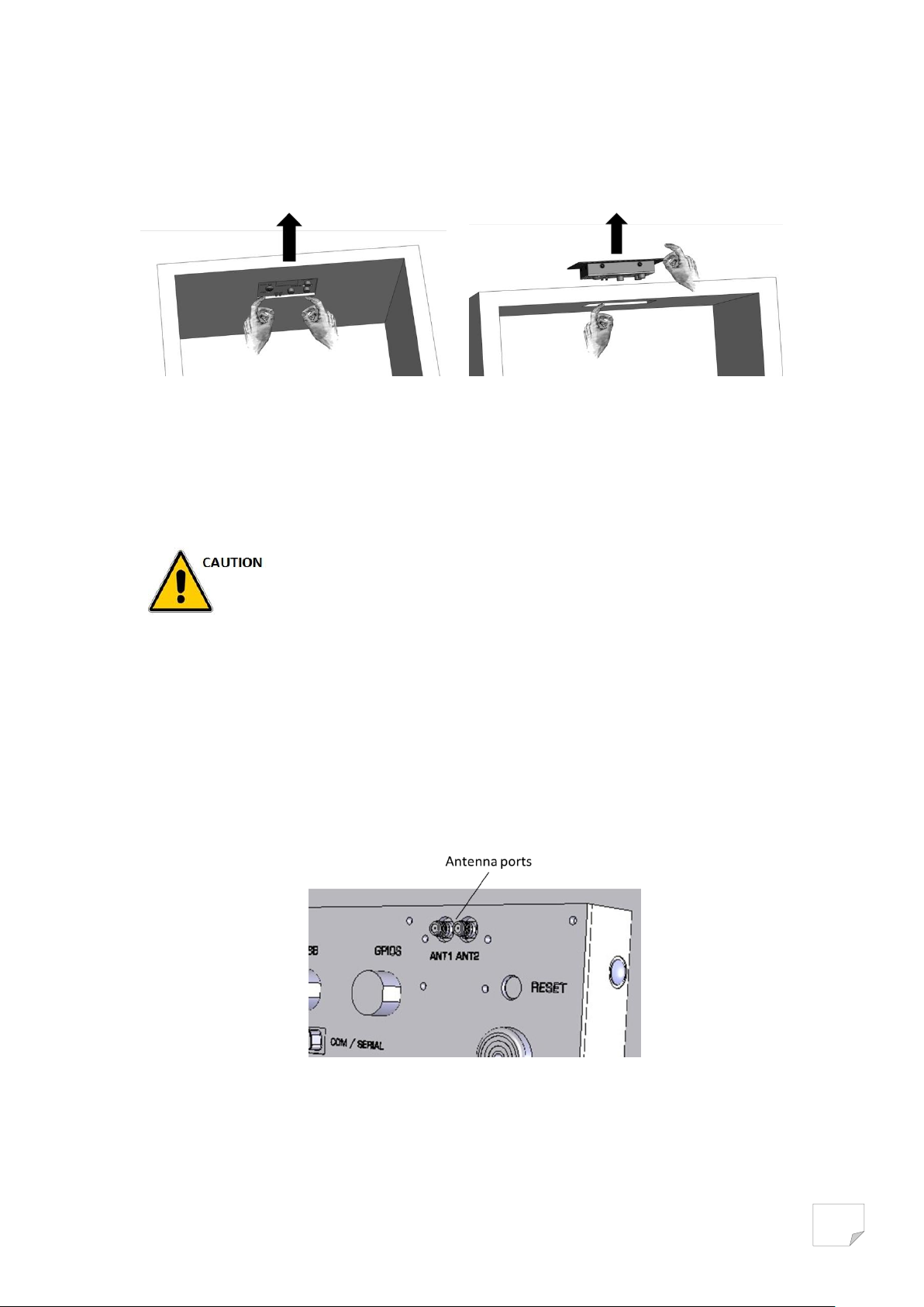
3. To remove the reader, press the reader from the bottom side and slide the reader up while
gently pulling out
Figure 5: EmbiPos reader removing from desk
Connecting antennas
1. For each external antenna, screw the antenna cable connector to one of the two antenna
ports
2. Please make sure that the antenna cables are not bend
Figure 6: Antenna ports illustration
Page 10
10
Connecting serial/RS232 cable
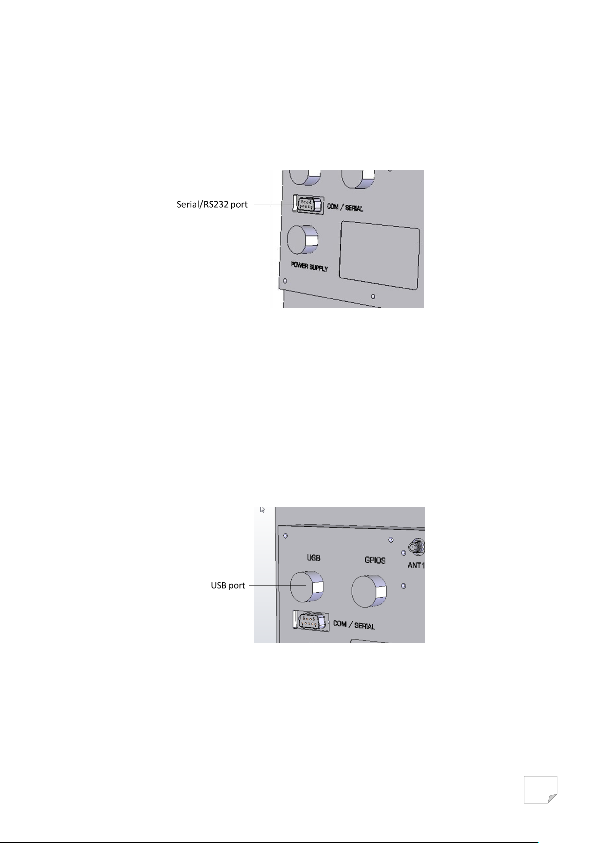
EmbiPos reader communicates with the host PC through a serial/RS232 communication.
1. Connect the serial cable to the serial/RS232 port of the reader
2. Fasten the screws of cable connector into the hole of host socket to secure the connection
Figure 7: Serial port illustration
Connecting USB cable
EmbiPos is able to communicate with host PC through an USB 2.0 interface.
The specific USB cable is available upon request as an accessory with your Embisphere sales service
1. Insert the USB cable (with the blue over molded plastic part) into the USB port of the reader,
connect the other part into USB port of your host PC
2. Fasten the screw of cable connector to secure the connection
Figure 8: USB port illustration
Page 11
11
GPIO interface
Please make sure that antennas are connecting before powering on your
device
Use only AC power supply provided with your EmbiPos
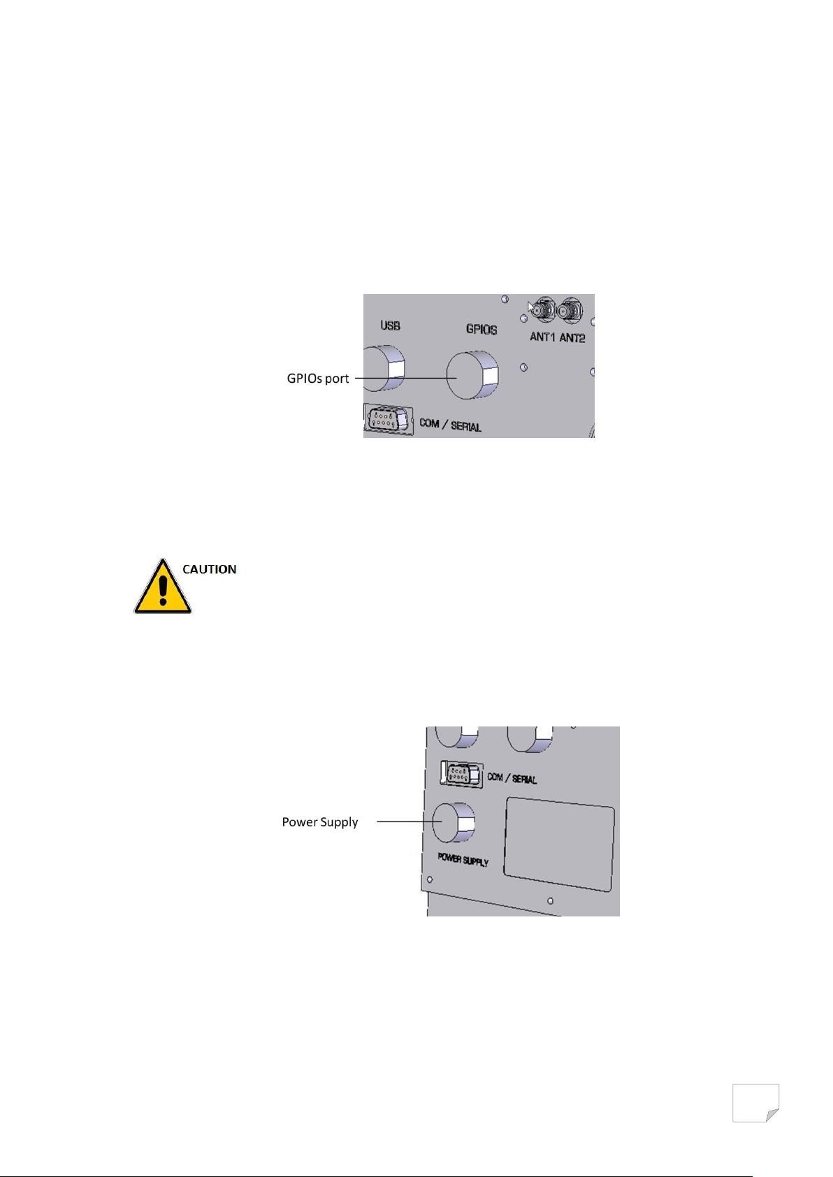
EmbiPos reader offers up to four general purpose outputs to drive for example 12V relays, indicator
LEDs, etc.
The GPIOs port of the reader needs a specific connector. Please contact your Embisphere
representative for any information.
The general purpose outputs are optically isolated 12V drivers. Each output can sink up to 200 mA
Figure 9: GPIOs port illustration
Powering the reader
The EmbiPos AC power supply provided with your product uses a specific locking connector.
1. Insert the power supply connector into the reader power port
Figure 10: Power supply port illustration
2. Fasten the screw of cable connector to secure the connection
3. Connect the AC power supply to a power outlet. The green power LED lights on to indicate
that the reader is powered on and the blue Led blinks to indicate the reader is ready
4. To power off the reader, remove the AC power supply from its power source. The green
power and blue LEDs light off.
Page 12

12
Reading UHF RFID tags
Please make sure that the tags that you want to read are located inside the
reading area of your embiPos reader
To test RFID reader capability of your reader, please launch RFID software commands
1. Present a tag to the RFID reading area
2. Each time the EmbiPos reads a tag, the orange Led blinks
3. Each time the reader reads a new tag, the buzzer beeps
4. Adapt the volume of the buzzer by pressing volume button
Page 13
13
2. TECHNICAL SPECIFICATIONS
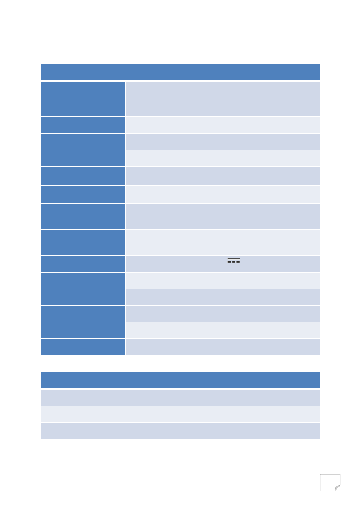
TECHNICAL DATA
RFID Frequency
ETSI (EU) 865.6 - 867.6 MHz
FCC (NA, SA) 902 – 928 MHz
SRRC-MII (China) 920 – 925 MHz
RFID Chip compatibility
EPCglobal Class 1 Gen 2 (ISO 18000-6C) with anti-collision
RFID Output power
From 10 dBm to 30 dBm (1W)
RFID Integrated Antenna
Circular polarized built-in antenna
RF Interface
2 SMA connectors for external antennas
General Purpose I/O
2 outputs, optically isolated. 0– 12V.
Communication
Secured USB
Serial RS232
User interface
LED indicators : Power, Communication, RFID read
Buzzer
Power Supply
100-240 V ~ 50-60 Hz 1,1A / 12 DC 4A external power adaptor
Operating temperature
0 °C / 60°C
Altitude
0 to 2000m
Construction
ABS choc
Dimensions (HxWxD)
24,5 cm x 18,5 cm x 33,3 cm
Weight
475 g
PACKAGING SPECIFICATIONS
Product Number
(01)3760209220018(21)EMPOS for EU Version
Package dimensions(HxWxD)
29 cm x 26 cm x 9,5 cm
Package weight
1400 g
Page 14

14
Problem
Possible solutions
The product don’t turn on
Verify that power adaptor and cable are well connected
I don’t succeed connecting my
EMBIPOS to host device by
RS232 or USB
Verify that the reader appears in the Windows device manager.
Otherwise please check cable connection.
I don’t succeed connecting my
EMBIPOS to host device by
RS232
Verify that the physical serial port used is coherent with that
defined into the software application
I don’t succeed connecting my
EMBIPOS to host device by
RS232 or USB
Verify the connection between the reader connectors and host
device
During RFID tags reading, the
orange LED don’t blink et the
buzzer don’t beep
You are perhaps located too far away from the RFID tags. Try to get
closer.
3. TROUBLESHOOTING
Page 15

15
For any issue, remark or suggestion, please contact:
EMBIPSHERE
11 Avenue de l’harmonie – HUB innovation
59650 Villeneuve d’Ascq
FRANCE
www.embisphere.com
 Loading...