

Page 1
GB
User‘s manual
D
Bedienungsanleitung
F
Manuel d’utilisation
IT
Manuale di istruzioni
NL
Gebruikershandleiding
ES
Manual de usuario
PL
Instrukcja obsługi
TUAREG 92 EVO
APACHE 92 EVO
(CROSSJET)
TUAREG 92 4x4 EVO
APACHE 92 4x4 EVO
(CROSSJET 4x4)
Page 2
2
1.2
1
7
5
4
6
3
2
1.3.1
TYPE N°: AJ-102
ENGINE: B 3 6 9
YEAR OF PRODUCTION: xxxx
WEIGHT: 299kg
FABRICATION: Seco GROUP a.s., BRANCH PLANT 02
Jicin , Jungmannova 11
Czech Republic
&S 2 HP VANGUARD (1 . KW)
MADE IN EUROPE
1
2
3
4
5
6
7
8
9
CE CONFORMITY: 2006/42/EC;2004/108/EC
2000/14/EC;2002/88/EC
1.3.2a
100
dB
Page 3
3
1.3.2b
MAX
18
o
1.3.2c
1.3.2d
Page 4
4
3.1
2
3
5
4
1
3.3a
Page 5
5
3.3b
2
1
3.3c
Page 6
6
3.3d
4.1
3
4
5
6
7
8
2
1
Page 7
7
6.3.13
AC 92-18(20) AC 92-23 4x4
MIN
MAX
6.4
50
50
5050
50 50
50
10
50
Page 8
8
FOREWORD
Dear customer,
Thank you for purchasing this riding mower from Seco GROUP a.s., a company renowned both in Europe and
internationally as a manufacturer of quality machines and accessories for the maintenance of grass areas.
This user’s manual includes instructions about the safe assembly, operation and maintenance of your machine.
Study this user‘s manual carefully. Follow the instructions contained in this user‘s manual
precisely so that operating the machine is easier and that it is used optimally and has a long
lifetime. Do not use the machine until you have thoroughly read all instructions,
restrictions and recommendations contained in this user’s manual.
Keep the user‘s manual for future use. This user‘s manual needs to be considered a part of
the riding mower that must be included with the tractor in the event that it is sold.
If anything is unclear or you have questions, do not hesitate to contact one of our more that
100 authorised, professionally-equipped service centres located all over Europe, where trained and
tested experts will be ready to assist you.
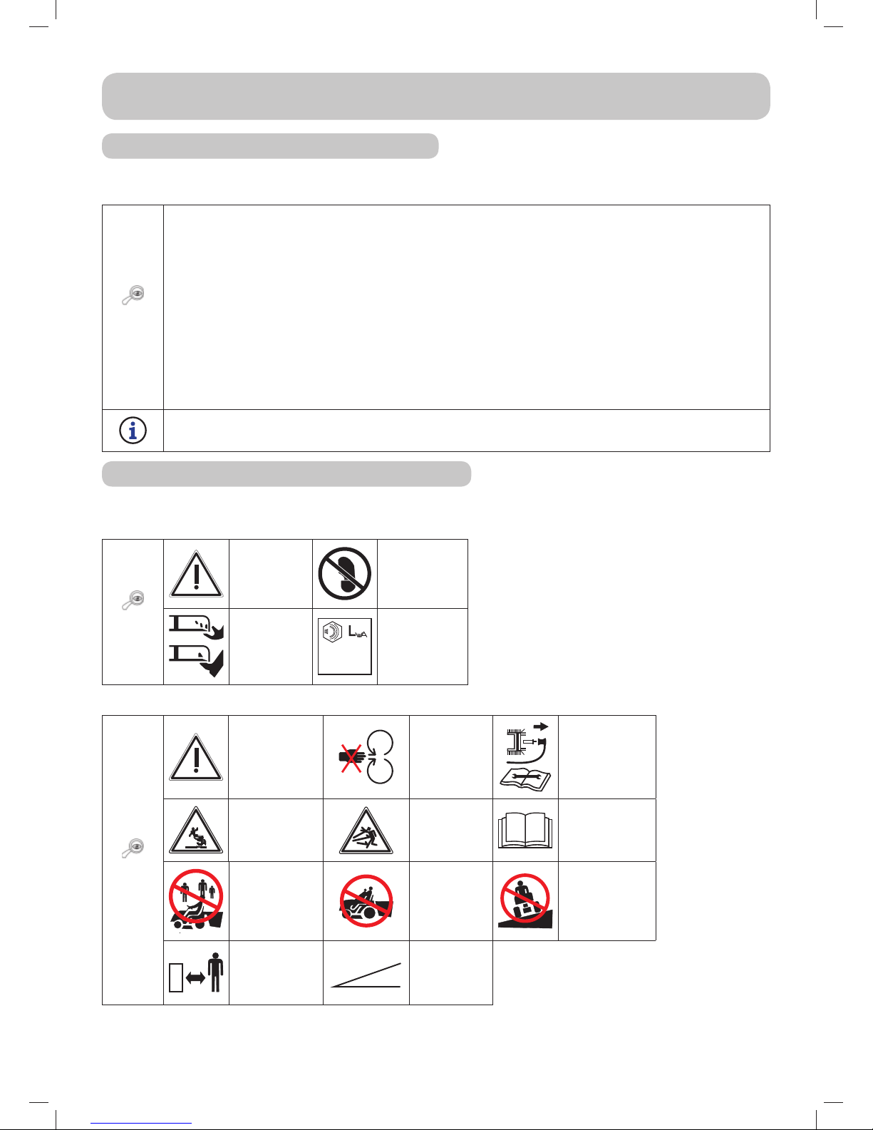
SYMBOLS USED IN THIS USER‘S MANUAL
SYMBOL MEANING
These symbols mean „ATTENTION” and “WARNING”, they inform you about things that
may damage your machine and/or cause serious injury to the user.
This symbol indicates an important instruction, property, procedure or issue, which you
need to be aware of and adhere to during assembly, operation and maintenance of the
machine.
This symbol indicates useful information relating to the machine or to its accessories.
The symbol is a reference to an image in the front part of the user‘s manual. It is always
accompanied by the number of the image.
This symbol is a reference to another chapter in this or another user‘s manual and most
often it is shown together with the number of the chapter to which it refers.
REFERENCES TO DIRECTIONS
Left and right side Front and rear side
L
R
R
F
L = Left side, R = Right side R = Rear side, F = Front side
Page 9

9
1. TECHNICAL INFORMATION
1.1 USE
The machine model AC92-18(20) or AC92-23 4x4 under the brand name CROSSJET is a dual-axle
terrain riding mower designed for mowing maintained and unmaintained grass-covered level and
sloped areas up to an incline of 18°(32%), that are free of foreign objects (stones, fallen branches,
bones, hard items, etc.). It can be used to mow multi-year vegetation, intertwined with raspberries,
blackberries and various other weeds.
Any use of this riding mower, which is not described in this user’s manual and which
goes beyond the use here described is considered to be in contradiction to its
intended purpose or use. The manufacturer of the machine is not responsible for damages
arising from such use; the risk is borne by its user. The user is also responsible for adhering
to the conditions prescribed by the manufacturer for the operation, maintenance and repairs
of this machine, which may only be used, maintained and repaired by persons that
know these conditions and have been informed about possible dangers.
Only accessories, which have been approved by the manufacturer may be connected
to the machine. The use of other accessories will result in the warranty being
immediately void.
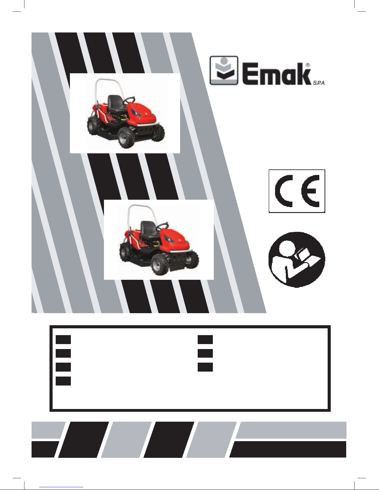
1.2 MAIN PARTS OF THE RIDING MOWER
Riding mower models AC 92-18, AC 92-20 or AC 92-23 4x4 consist of the following basic sections:
1.2
(1) Hood with storage space
The hood is a combination of plastic and metal covers, which contain the storage space for
the battery.
(2) Frame with a bumper
The frame with the bumper serve as a bearing element for most of the main parts of the
machine.
(3) Front axle with wheels including steering*
The front axle enables the wheels to turn. The wheels are turned by the steering wheel by
means of a comb mechanism.
The AC 92-23 4x4 machine is equipped with front-wheel drive. All-wheel drive is activated
automatically, with power distributed to the individual axles depending on the current
traction conditions and the travel mode (forward or reverse).
(4) Mower deck
The mower deck mows the grass. It is located under the machine. It consists of a cover,
main plate, blade holders and two massive mowing blades. The deck is powered by the
machine’s engine through an electromagnetic clutch and a V-belt.
(5) Engine, gear box including rear-wheel drive via a by-pass
The four-stroke petrol engine is mounted to the frame in the rear part of the machine. The gear
box with hydrostatic power transmission serves to change gears while driving. The by-pass lever is
located on the machine’s rear plate. It serves to activate and disable the gear box for the rear wheels.
(6) Folding frame of the machine
The folding frame is intended to prevent the machine from rolling over by 180° if for any
reason it loses stability and rolls on to its side.
(7) Driver’s location
The comfortable seat enables easy access to all control elements on the machine. The seat
used ensures safe and comfortable operation.
*ATTENTION: The AC92-23 4x4 machine does not enable for construction reasons the
disconnection of the front axle drive – the hydraulic system is not equipped with a by-
pass valve, which significantly limits the option of moving the machine when the engine
is not running. During such movement the front axle is significantly overloaded and may
be damaged. The by-pass lever on this machine is primarily used to bleed the hydrostatic
system. The machine must not be used (gear shifted into drive) if the by-pass lever is in the
disengaged position - there is a danger of damage to the transmissions!!
Page 10
10
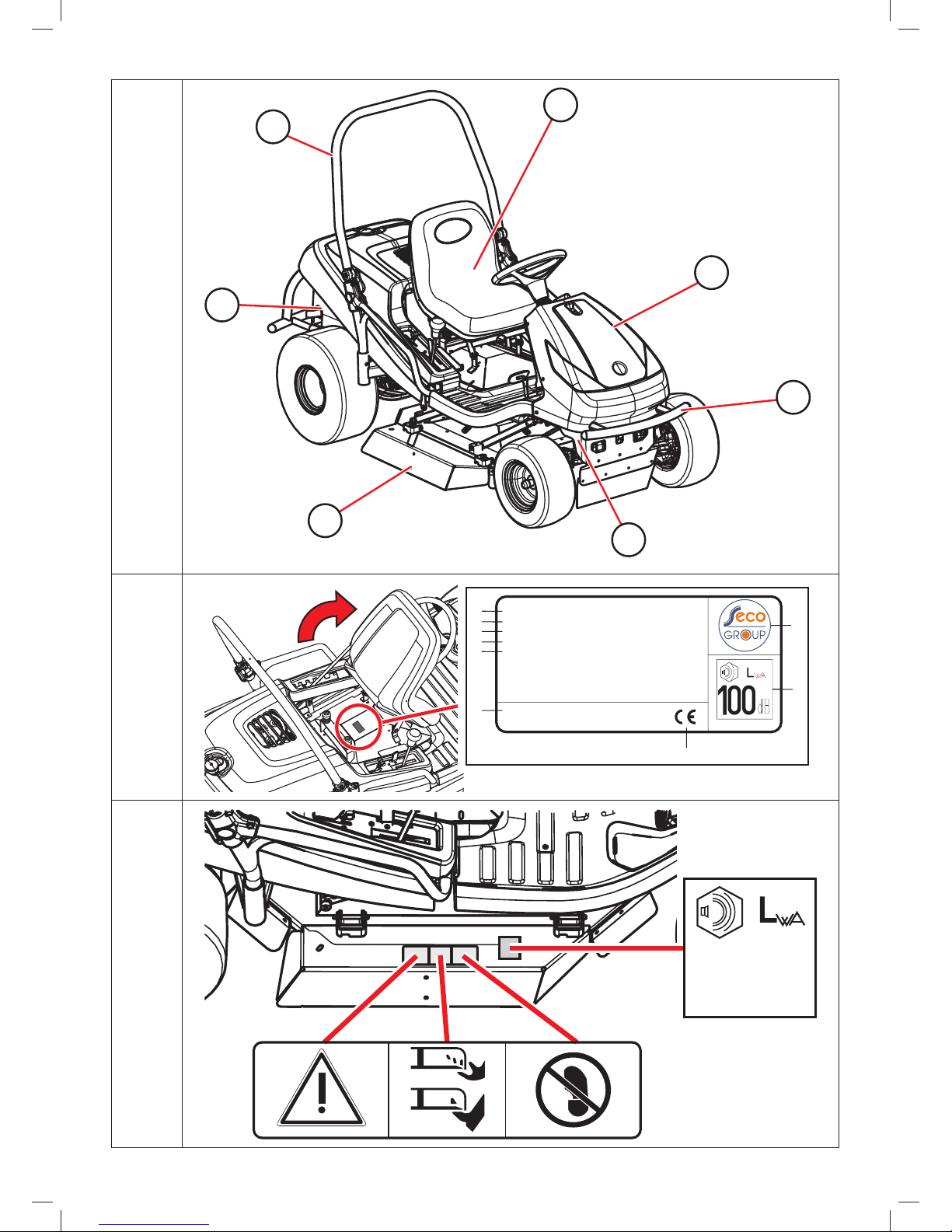
1.3 PRODUCT IDENTIFICATION LABEL AND OTHER LABELS WITH
SYMBOLS USED ON THE MACHINE
1.3.1 PRODUCT IDENTIFICATION LABEL
Every riding mower is marked with a product identification label, located underneath the seat. It can
be accessed by lifting the seat.
1.3.1
1. Machine model
2. Engine model
3. Year of production
4. Weight
5. Name and address of the manufacturer
6. EC codes used to assess the product’s compliance
7. Compliance mark of the product
8. Logo of the manufacturer
9. Guaranteed noise level according to directive 2000/14/EC
The seller will write down the serial number on the other side of the front page of this
manual when handing over the machine.
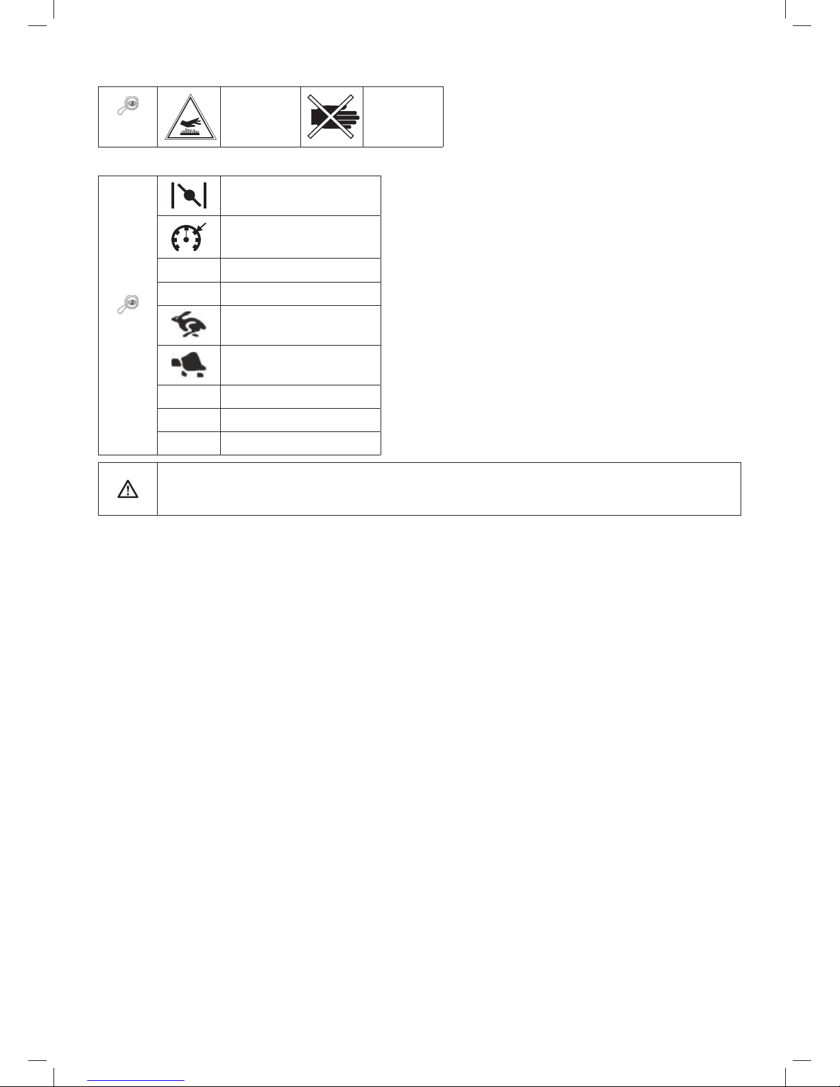
1.3.2 OTHER LABELS AND THEIR MEANINGS
The following labels and stickers are attached to the machine:
Labels on the mowing deck:
1.3.2a
Danger
Do not step
on
Rotating
tools
100
dB
Guaranteed
noise level
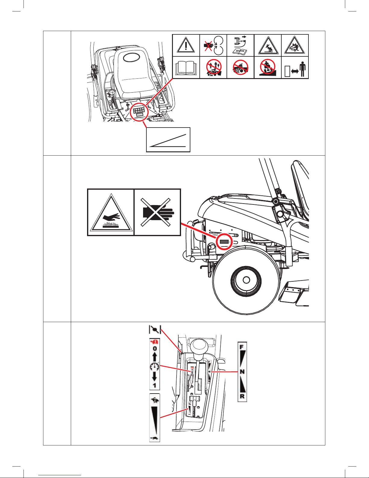
Labels on the fairing under the seat:
1.3.2b
Danger
Do not
touch
during
operation
Follow the
manual when
repairing
Do not leave
the machine
when driving
Caution,
deflected
objects
Read the
manual
Do not mow
near other
people
Do not
take on
passengers
Do not drive
perpendicular
to the slope
Keep
unauthorised
persons at a
safe distance
MAX
18
o
Maximum
working
incline
Page 11
11
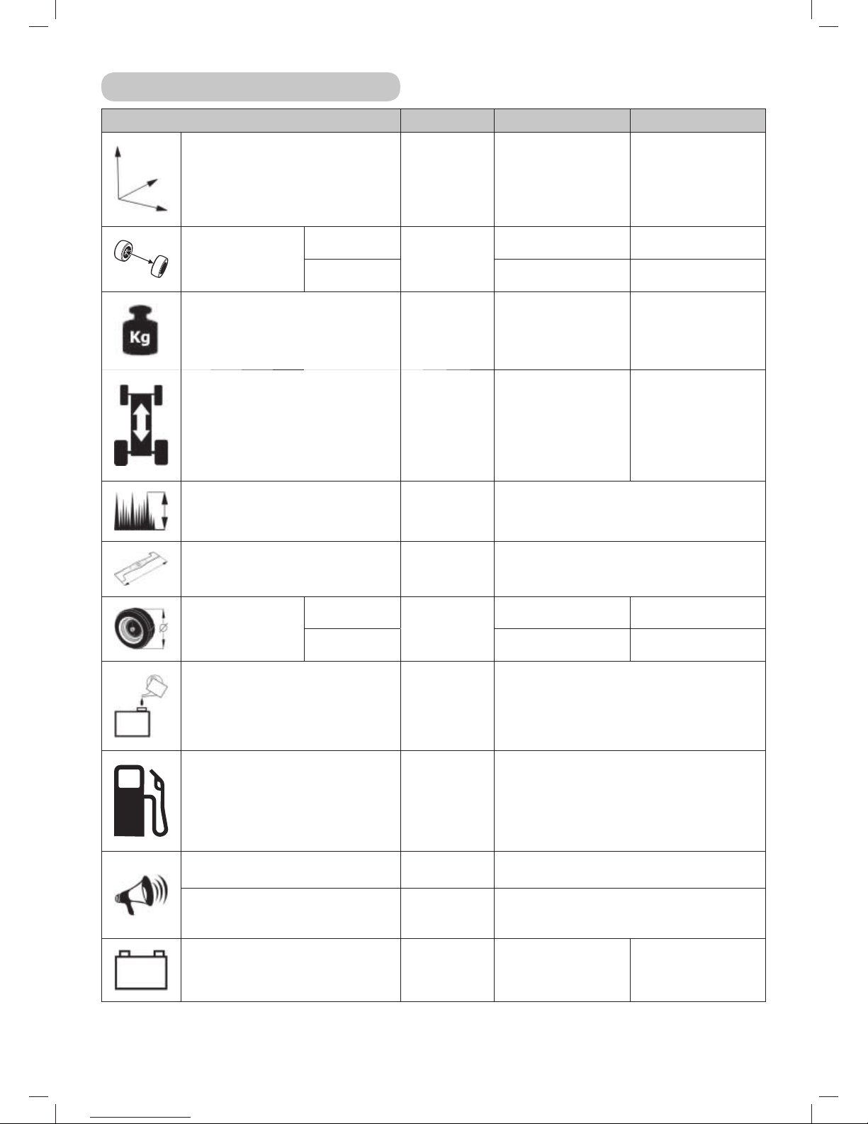
Labels on the rear side of the machine:
1.3.2c
Careful
Hot
surface!
Danger of
burns
Labels at the travel direction lever:
1.3.2d
Choke
Cruise control
0
Cruise control activated
1
Cruise control deactivated
Fast
Slow
F
Travel forward
N
Neutral
R
Travel in reverse
It is strictly forbidden to remove or damage labels and symbols attached to the
accessory. In the event of damage or illegibility of the label, please contact the supplier or
machine manufacturer and request a replacement.
Page 12
12
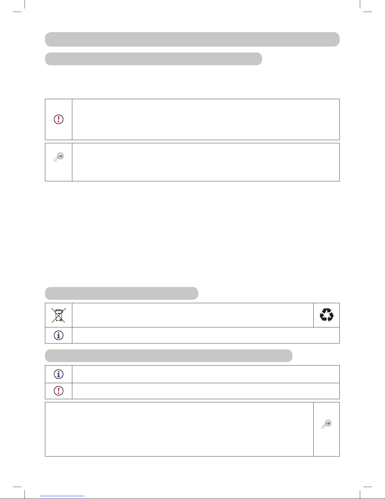
1.4 TECHNICAL PARAMETERS
BASIC PARAMETERS UNITS AC 92-18 (20) AC 92-23 4x4
Dimensions of the machine
(length x width x height)
[mm] 2310 x 1010 x 1510 2310 x 1050 x 1510
Wheelbase
Front
[mm]
814 814
Rear 780 790
Weight of the machine [kg] 317 350
Speed forward / reverse [km/h] 0-8.5 / 0-4.5 0-9 / 0-5
Mowing height [mm] 50-100
Mowing width [mm] 920
Wheel dimensions
Front
["]
16x6.5-8 16x6.5-8
Rear 20x10.0-8 20x10.0-8
Fuel tank capacity [l] 12
Fuel type --- Lead-free petrol Natural 95
Guaranteed emission level of
acoustic power L
WA
[dB] <100
Declared emission level of acoustic
pressure at the place of operation
L
pAd
according to EN ISO 11201
[dB] <100
Type of battery --- 12V 24aH 12V 32aH
* - for specific values see the table on the next page.
Page 13

13
Engine
Revolutions
±100
(min-1)
Declared emission level
of acoustic pressure at
the place of operation
L
pAd
(dB) according to
EN ISO 836+A1/A2,
Annex H and EN ISO 11201
Vibration acceleration aggregate value (m.s
-2
)
according to EN 836+A1/A2, annex G
seat
steering
wheel
floor
BS18 3000 88.4 0.23 2.38 1.61
total vibrations a
v
according to
EN 1032
vibrations transferred to
the arm a
hv
according to EN 1033
BS20 3000 90 0.56 < 2.5
BS23 3000 91 1.5 < 2.5
Page 14

14
2. WORK SAFETY AND HEALTH
Riding mowers models Ac 92-18, AC 92-20 and AC 92-23 4x4 under the brand name CROSSJET are
manufactured according to valid European safety norms. The machine’s manufacturer confirms this
fact in the Statement of compliance, which is included at the end of this user’s manual ( 10).
If this machine is used properly and according to the user’s manual, it is very safe.
In the event that work safety is not adhered to and all warnings in this manual are
not respected, this riding mower may cut off hands, legs or deflect objects and
so may cause serious injury or death to persons, damage or destructions of the
machine or one of its parts or accessories.
2.1 SAFETY INSTRUCTIONS
The person primarily responsible for their own safety and the safety of others during the operation
of the riding mower is its user. The manufacturer takes no responsibility for the injury of persons or
damage to the machine and ecological damage resulting from the machine not being used and operated
in accordance with all safety instructions included in this user’s manual.
2.1.1 GENERAL SAFETY INSTRUCTIONS
! This machine may only be driven by a person over 18 years of age that has read this user’s manual.
! The user of the machine is responsible for the safety of persons in the vicinity of the working area of
the machine.
! It is not permitted to perform any technical modifications to the machine and its accessories without
the manufacturer’s written consent. Unauthorised modifications may lead to hazardous work safety
conditions and void the warranty.
! Adhere to all requirements relating to fire safety (
2.4).
! Do not remove safety stickers or labels from the machine.
! Do not stay in the vicinity of the machine or under it, if it is lifted and is not sufficiently secured
against falling or tipping over in the lifted position.
! Always turn off the mowing deck and engine and take the key out of the ignition, when:
you are cleaning the machine
you are removing accumulated grass from the mowing deck
you have driven over a foreign object and it is necessary to check whether the machine has been damaged
or it is necessary to remedy the damage
the machine is vibrating with unusual force and it is necessary to identify the cause of the vibrations
you are repairing the engine or other moving parts (also disconnect cables from the spark plugs)
2.1.2 BEFORE USING THE MACHINE
! Do not use the riding mower if it is damaged or if any of its protective elements are missing. All covers
and other protective elements must always be in their place. Therefore, do not remove or put out of
operation any of the machine’s protective elements. Regularly check that these elements are working
correctly.
! Do not work with the machine after consuming alcohol, drugs or medication affecting your perception.
! Do not work with the machine if you suffer from dizziness, fainting or if you are weakened or distracted
in any other way.
! Before putting the machine into operation thoroughly learn about all the control elements and ensure
that you can control them in such a way that if necessary you can immediately stop or turn off the
engine.
! Do not adjust the engine regulator or the engine speed limiter.
! Before you start working with the machine, remove from the surface of the area you will be mowing,
all stones, pieces of wood, wire, bones, fallen branches and other items, which could be deflected
during the mowing process.
Page 15

15
! Remove all defects before further use. Before starting work thoroughly check that the belts are
tensioned, the blades are sharp and that the area inside the mowing deck is clear.
2.1.3 WHILE OPERATING THE MACHINE
! As this machine is intended for mowing grass on unmaintained areas where the operator may not
always have full visibility and knowledge of the condition of the area being mowed (trenches or holes),
the machine is equipped with a folding frame.
! The machine must not be used for work on slopes with an incline greater than 18° (32%), and when
using the 4x4-drive on slopes with an incline greater than 20°(32%).
! Transport of other passengers, animals or loads directly on the machine is forbidden. Transport of
loads is only permitted on trailers approved by the machine’s manufacturer.
! Even when leaving the machine for a short time, always remove the key from the ignition.
! If you are driving the machine away from the work area where you are mowing, always disengage the
mowing deck and lift it to the transport position.
! Do not mow near piles of material, holes or banks. The riding mower may suddenly roll over if the
wheel goes over the edge of a hole, trench or an edge that may collapse.
! When working, avoid concrete supports, tree stumps, garden bed and footpath kerbs, which must
not come into contact with the blades and so cause damage to the mowing deck and the machine’s
mechanism.
! In the event of an impact into a rigid object, stop and turn off the mowing deck and engine and
inspect the entire machine, particularly the steering mechanism. If necessary perform repairs before
starting up the engine again.
! Whenever possible avoid using the machine in wet grass. Reduced traction may lead to skidding.
! Avoid obstacles (e.g. sudden change in the incline of a slope, trenches, etc.) on which the machine
could roll over.
! If mowing is disengaged, the mowing deck must always be in the transport position.
! Do not attempt to maintain the stability of the machine by stepping on the ground.
! Only use the machine in daylight hours or with good artificial lighting.
! Driving the machine on public roads is not permitted.
! When operating the machine do not wear loose clothing and short pants, use solid fully-closed
footwear. Never operate the machine when wearing sandals or barefoot.
! Do not leave the engine running in closed areas. The exhaust fumes contain substances that are
odourless but are fatally poisonous.
! Do not put your hands or legs underneath the mowing deck cover. Never put any part of your body
near the rotating or moving parts of the machine.
! Do not start the engine without an exhaust.
! Usually the noise emitted during mowing does not exceed the acoustic pressure and acoustic power
values specified in this user’s manual (
1.4). In certain cases, however, it may under certain
conditions and due to the condition of the terrain exceed the specified noise levels for a short time.
! The machine manufacturer recommends the use of hearing protection when operating the machine
because stressing the hearing organ with an excessive noise level or long term effects of noise may
lead to permanent hearing damage.
! Always pay full attention to driving and other activities performed with the machine. The most common
causes of loss of control over the machine are for example:
Loss of wheel traction.
Excessive speed, not adjusting speed to current conditions and terrain properties.
Sudden breaking where the wheels lock up.
Using the machine for purposes for which is was not designed.
Page 16

16
2.1.4 AFTER FINISHING WORK WITH THE MACHINE
! Always maintain the machine and its accessories clean and in good technical condition.
! The rotating blades are sharp and may cause injuries. Whenever handing the blades always use
protective gloves or wrap the blades.
! Regularly check the nuts and bolts securing the blades so that they are tightened with the appropriate
amount of torque (
6.3.6).
! Pay special attention to lock nuts. After the nut is loosened a second time its locking capability is
reduced and therefore it needs to be replaced with a new one.
! Regularly inspect all components and if necessary replace those that need to be replaced based on
the manufacturer’s recommendations.
2.2 SAFETY INSTRUCTIONS FOR WORK ON SLOPES
Slopes are the main cause of accidents, loss of control over the machine or subsequent roll-overs,
which may lead to serious injuries or death. Mowing on slopes always requires an increased level of
attention. If you are not sure, or it exceeds your ability, do not mow on slopes.
! Riding mowers can be used on slopes with a maximum incline up to 18° (32%) and when 4x4-drive
is used on slopes with a maximum incline of 20°(32%) and only in the direction of the fall line, i.e.
upwards or downwards. More information
5.5.4.
! When changing direction increased care is needed. Do not turn on a slope unless it is absolutely
necessary.
! Watch out for holes, roots, uneven terrain. Uneven terrain may cause the machine to turn over. High
grass may conceal hidden obstacles. Therefore, remove all foreign objects from the area where you
wish to mow in advance.
! Select such a speed so that you do not need to stop when on a hill.
! Be very careful when attaching various hitch attachments. It may lead to a reduced stability of the
machine.
! Perform all movements on a slope slowly and smoothly. Do not make sudden changes to speed or
direction.
! Avoid starting up or stopping on a slope. In the event that the wheels lose traction, turn off the power
to the blades and drive slowly down the hill.
! Start driving very carefully and slowly when on a slope so that the machine does not “skip”. Always
reduce the machine’s driving speed before a slope, and especially when driving down a hill lower the
driving speed to minimum to take advantage of the braking effect of the transmission. This braking
effect is significantly higher on the AC 92-23 4x4 machine.
2.3 CHILD SAFETY
If the riding mower operator is not prepared for the presence of children then a tragic accident may
happen. The movement of a riding mower attracts the attention of children. Never assume that children
will remain in the location where you last saw them.
! Do not allow children without supervision in areas where you are mowing grass.
! Always be prepared - if children approach you then turn off the machine.
! Before and while reversing look behind you and at the ground.
! Never transport children, they may fall and seriously injure themselves, or they may dangerously
interfere with the riding mower controls. Never allow children to operate the machine.
! Pay increased attention in places with limited visibility (near trees, bushes, walls, etc.).
Page 17

17
2.4. FIRE SAFETY
When reversing the riding mower it is necessary to adhere to fundamentals and regulations for
work safety and fire protection relating to work with this type of machine.
! Regularly remove flammable substances (dry grass, leaves, etc.) from the area around the exhaust,
engine, battery and anywhere, where they could come into contact with petrol or oil and subsequently
catch on fire and so result in a fire on the machine.
! Allow the riding mower engine to cool down before parking it in a closed location.
! Pay increased attention when working with petrol, oil and other flammable substances. These are
very flammable substances, the fumes of which are explosive. Do not smoke during this work. Never
unscrew the petrol tank cap and refill with petrol while the engine is running, if the engine is hot or if
the machine is in a closed location.
! Check the petrol lines before using and do not fill the petrol all the way up to the bottleneck of the
tank. The heat generated by the engine, sun and the expansion of the fuel may lead to the petrol
overflowing and a subsequent fire.
! For storing flammable substances use containers designed for this purpose. Never store a canister
with petrol or the machine inside a building near any source of heat.
! Pay increased attention when working with the battery. The gas inside the battery is highly explosive,
therefore do not smoke in the vicinity of the battery and do not use an open flame so as to avoid
serious injuries.
Page 18
18
3. PREPARING FOR THE MACHINE FOR OPERATION
3.1 UNPACKING AND INSPECTING THE CONTENTS
The riding mower is supplied wrapped and in crate packaging. For transportation reasons some machine
assemblies are disassembled in the production plant and it is necessary to install them before putting
the machine into operation. The unpacking and preparation for operation is performed by the seller
within the scope of the pre-sale service.
Inspect immediately after delivery that the packed machine has not been damaged. In
the event of damage inform the carrier. If the complaint is not lodged in time, no potential
demands can be claimed.
Check that the machine model is the same as you ordered. In the event of an irregularity do
not unpack the machine and immediately report this discrepancy to the supplier.
3.1
1. Crate packaging
2. Seat
3. Folding frame
4. Steering wheel
5. Documentation (located underneath the hood)
Using a suitable tool (e.g. crowbar or hammer, etc.) remove the crate (1) and the packaging on the
machine.
Visually inspect the machine and assemblies for damage that may have occurred during transport.
Unpack all separatelz packed assemblies and inspect them.
The basic package includes:
Riding mower
Seat (2)
Folding frame in the folded state (3)
Steering wheel (4)
Documentation (5) (packed parts list, user’s manual for the riding mower, user’s manual for the
engine, user’s manual for the battery, service log book)
3.2 DISPOSAL OF THE PACKAGING
After unpacking the machine ensure that the packaging material is properly
disposed of or recycled. The disposal must conform to relevant waste disposal laws
valid in the user‘s country.
Disposal may be performed by a specialised company.
3.3 ASSEMBLY OF THE SEPARATELY PACKED ASSEMBLIES
Due to the technical nature of this task the machine is prepared for operation by the seller
of your riding mower (according to the following instructions).
Before starting installation, remove all covering, protective and fastening materials.
a) Install the seat springs:
Tilt out the seat.
Unscrew the bolts holding down the seating spring under the bracket. Then install
the springs so that they are above the bracket.
Set the appropriate distance of the seat from the steering wheel by pressing the seat
positioning lever which is a part of the seat.
3.3a
Page 19
19
Under no circumstances should you sit on the seat before installing the seat springs into a
working state! A collision with the hood could occur and damage it.
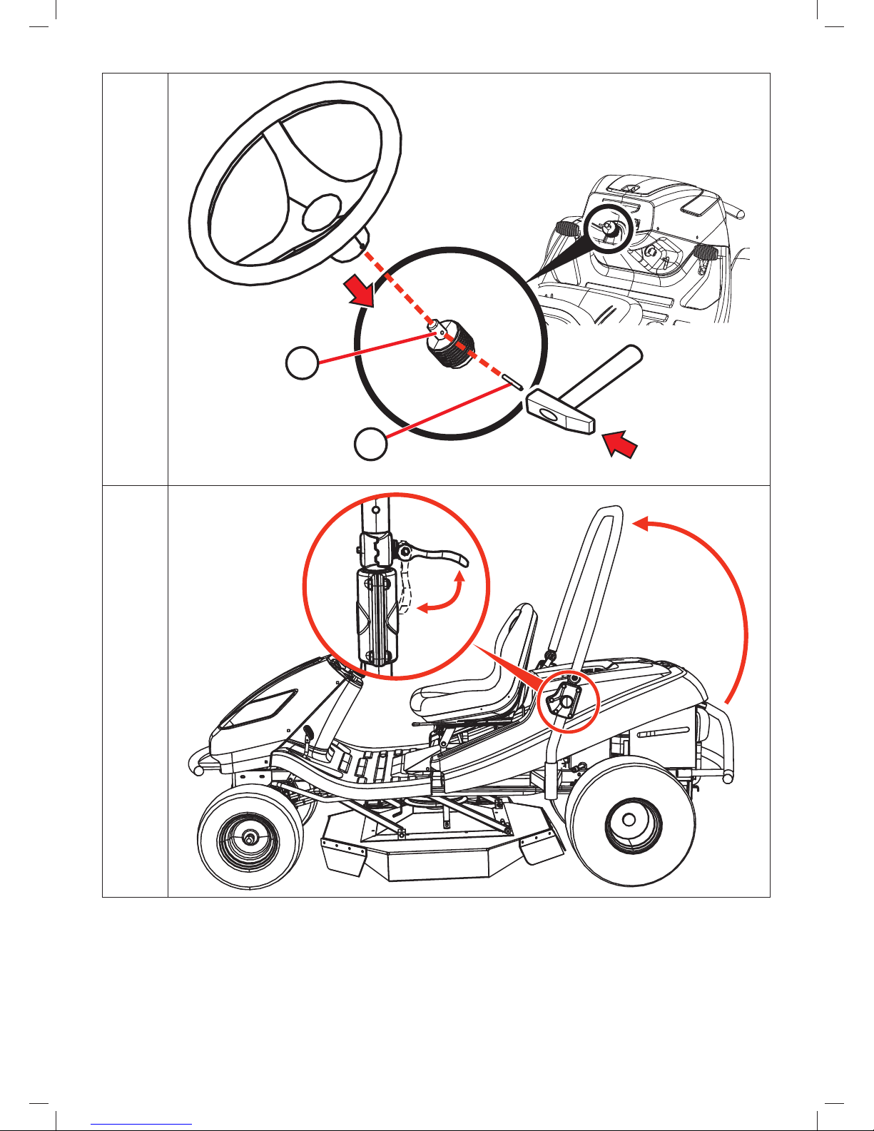
b) Install the steering wheel:
Using a hammer and a suitable rod, knock out the pin (2), which is inserted in the
shaft hole (1).
The steering wheel is set it two height positions, which are set by two holes in the
steering wheel shaft. Select the optimal steering wheel position, attach it on to the
shaft (1) and turn it so that the holes in the steering wheel and the shaft align.
Reinsert the pin into the hole and knock it in using a hammer.
3.3b
c) Set the folding frame to the correct position:
Using the quick coupler levers set the folding frame to the vertical position.
3.3c
d) Connect the battery:
Open the storage area in the hood and loosen the bolts on the battery pole terminals.
Black wire Place on the (+) pole of the battery and secure in place with the bolt.
Brown wire Place on the (-) pole of the battery and secure in place with the bolt.
3.3d
Connecting the wires in opposite to that described above will damage the machine.
When disconnecting the battery, always disconnect the negative (–) pole of the battery first.
When putting the battery into operation and when performing maintenance on it, proceed
according to the instructions in the user’s manual for the battery. Also follow all safety
instructions contained therein.
Now prepare the machine for the first start up according to the following chapter.
3.4 CHECKS PRIOR TO STARTING UP
Due to the technical nature of this task the machine is put into operation by the seller of your riding
mower (according to the manufacturer’s instructions).
3.4.1 CHECKING THE MOTOR OIL
The tractor must be in a horizontal position before the oil level can be checked. The cap of the filling
opening is located on the engine covers at the rear side of the machine. Screw out the oil dipstick, wipe
it dry, reinsert it and screw in. Then again screw it out and take the oil level reading.
Oil level dipstick:
(1) - (ADD) low oil level
(2) - (FULL) maximum oil level
The oil level must be between the two marks on the dipstick. If it is not, fill up with motor oil so that it
reaches the “FULL” mark. The motor oil type is indicated in the user’s manual of the engine.
The oil level must be checked before every work session.
3.4.2 CHECKING THE BATTERY
Check the battery charge level according to the user’s manual of the battery.
Page 20

20
3.4.3 FILLING THE FUEL TANK WITH FUEL
For safety reasons the riding mower is transported without fuel and before the first start up it is
necessary to fill it up. The fuel tank is located at the rear of the machine and has a capacity of 12 l of
fuel.
Use only petrol with the octane number specified in the user‘s manual of the engine, i.e.
lead-free petrol NATURAL 95. Defects caused by the use of incorrect fuel are not covered
by the warranty!
Only fill the fuel tank with the engine turned off and when the engine is cold. Fill up the fuel
tank in a well ventilated location.
When handling fuel, do not eat, smoke or use an open flame.
For filling use a funnel designed for refilling fuel.
Ensure that fuel is not spilled when refilling. Spilled fuel can very easily catch on fire. If fuel
does spill, thoroughly wipe dry.
Store fuels out of the reach of children.
Procedure for filling up:
Open the fuel tank cap. Open it slowly because there may be overpressure
in the fuel tank caused by petrol vapours.
Insert a funnel into the fuel tank opening and start to pour the fuel from
the canister.
After filling up the fuel tank always wipe dry the area around the fuel tank
opening as well as the fuel tank opening itself. It is good to check the
condition of the fuel lines.
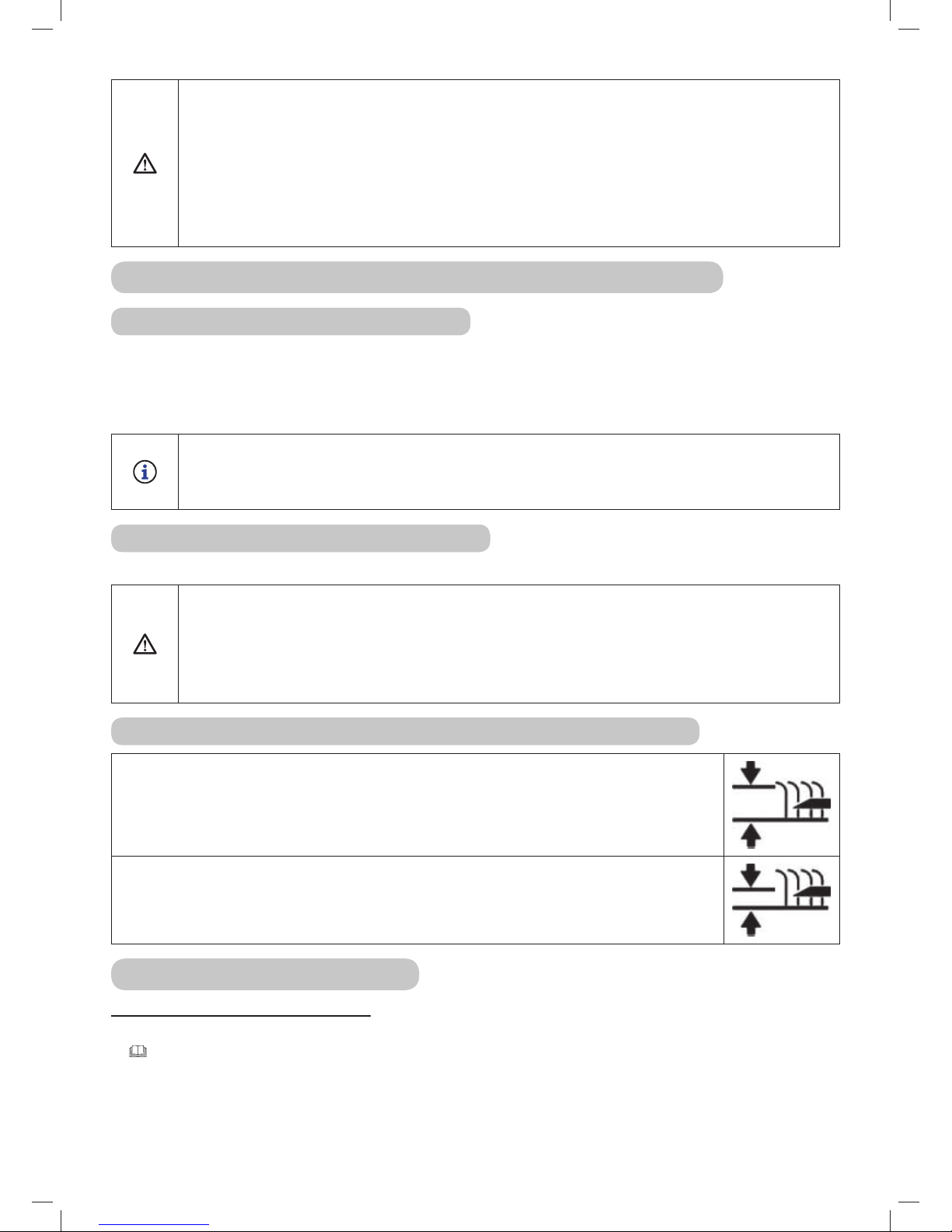
3.4.4 CHECKING THE AIR PRESSURE IN THE TYRES
Before putting the machine into operation, check the air pressure in the
tyres.
The air pressure in the front tyres must be 150 kPa.
The air pressure in the rear tyres must be 80 kPa.
The difference between the individual tyres may be ± 10 KPa.
150 kPa
80 kPa
Do not exceed the maximum pressure marked on the tyres that
are being used.
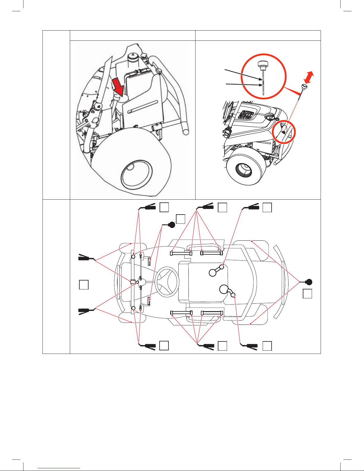
3.4.5 CHECKING THE OIL LEVEL IN THE HYDRAULIC CIRCUIT (APPLIES TO MODEL
AC 92-23 4X4)
The machine is supplied with a bled hydraulic circuit and with an equalisation tank with the prescribed
amount of oil. The oil level in the tank may decline during transport.
The equalisation tank is located in the rear part of the machine under the engine cover.
Check that the oil level is between the two marks on the dipstick of the closing cap, if necessary fill up
with the necessary amount of the prescribed oil.
Wipe clean the area around the tank opening and the tank opening itself. Also regularly clean the
entire tank, because any dirt in the oil reduces the lifespan of the oil filter and may possibly cause a
malfunction.
The system is fully bled during the first couple of hours of driving the machine – we recommend that
you “run the machine in” with a mild load for 1 to 2 hours.
Page 21
21
3.4.6 PERFORMING A LEAK TEST ON THE HYDRAULIC CIRCUIT
Visually check the hydraulic circuit for oil leaks, namely the locations where fittings are connected to
the transmissions. If you discover any leaks, inform your service centre.
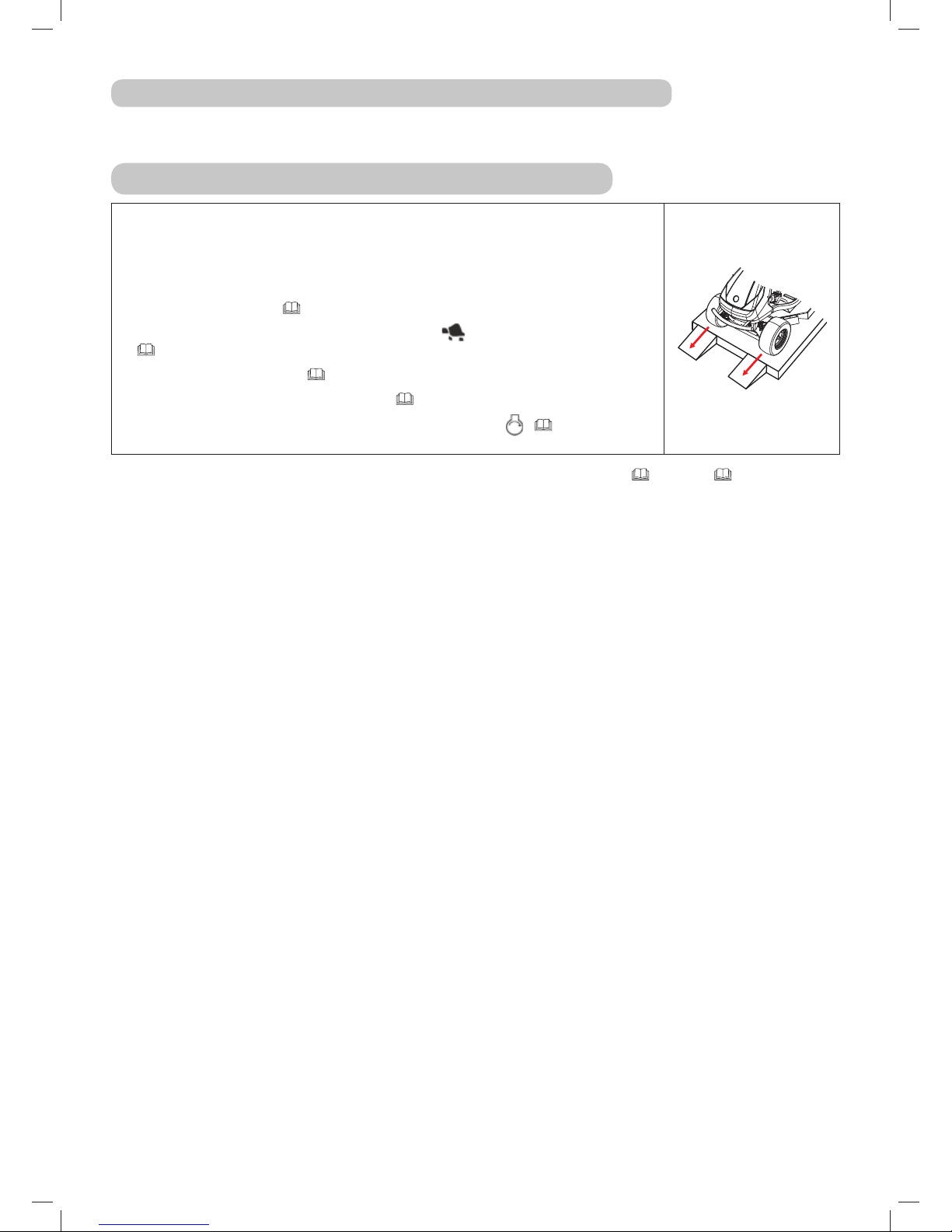
3.5 DRIVING THE MACHINE FROM THE PALLET
Prepare two suitable ramps and place them next to the pallet so that the
machine’s wheels can ride on to them. If you drive off the pallet without
ramps, there is a danger of damaging the underside of the machine,
particularly the mowing deck!
Lift the mowing deck into the transport position by pulling on the mowing
deck elevation lever (
4.2.1 (10)).
Move the throttle lever from position
approximately half way
( 4.2.1 (5)).
Pull out the choke lever (
4.2.1 (6)).
Set the by-pass lever to position “1” (
4.2.1 (11)).
Start up the machine by turning the key to position
( 4.2.1(1)) and
slowly drive the machine down off the pallet.
Further details about starting up and stopping the engine are provided in 5.2 and 5.3.
Page 22
22
4. OPERATING THE MACHINE
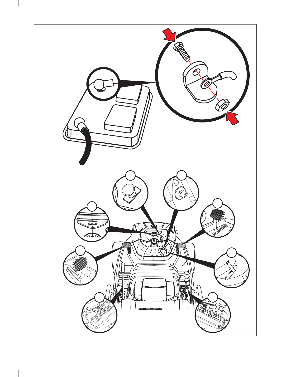
4.1 LOCATION OF THE MAIN CONTROL ELEMENTS
4.1
(1) Main power switch
(2) Brake pedal
(3) Parking brake lever
(4) Travel direction lever, throttle lever, choke and cruise control disengage lever
(5) Mowing deck elevation adjustment lever
(6) Differential lock pedal
(7) Motor hours counter
(8) Mowing deck activation switch
4.2 DESCRIPTION AND FUNCTIONS OF THE CONTROL ELEMENTS
4.2.1 STANDARD CONTROL ELEMENTS
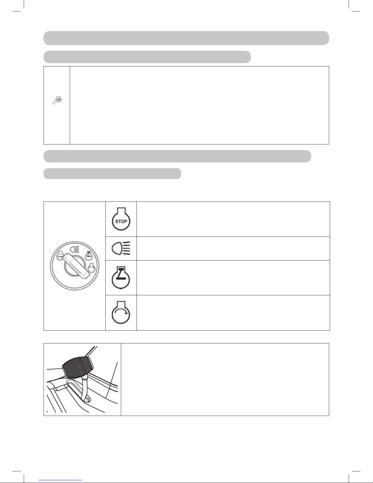
(1) MAIN POWER SWITCH
Serves to start up / shut off the engine. It has the following 4 positions:
Ignition off / turn off the ignition
Turn on / turn off the headlights on the hood
Ignition on, the engine is running.
Start engine – starting position
(2) BRAKE PEDAL
Pressing the brake pedal will slow down the riding mower.
Never use the brake at the same time as the travel direction function –
there is a danger of damaging the transmission!
Page 23
23
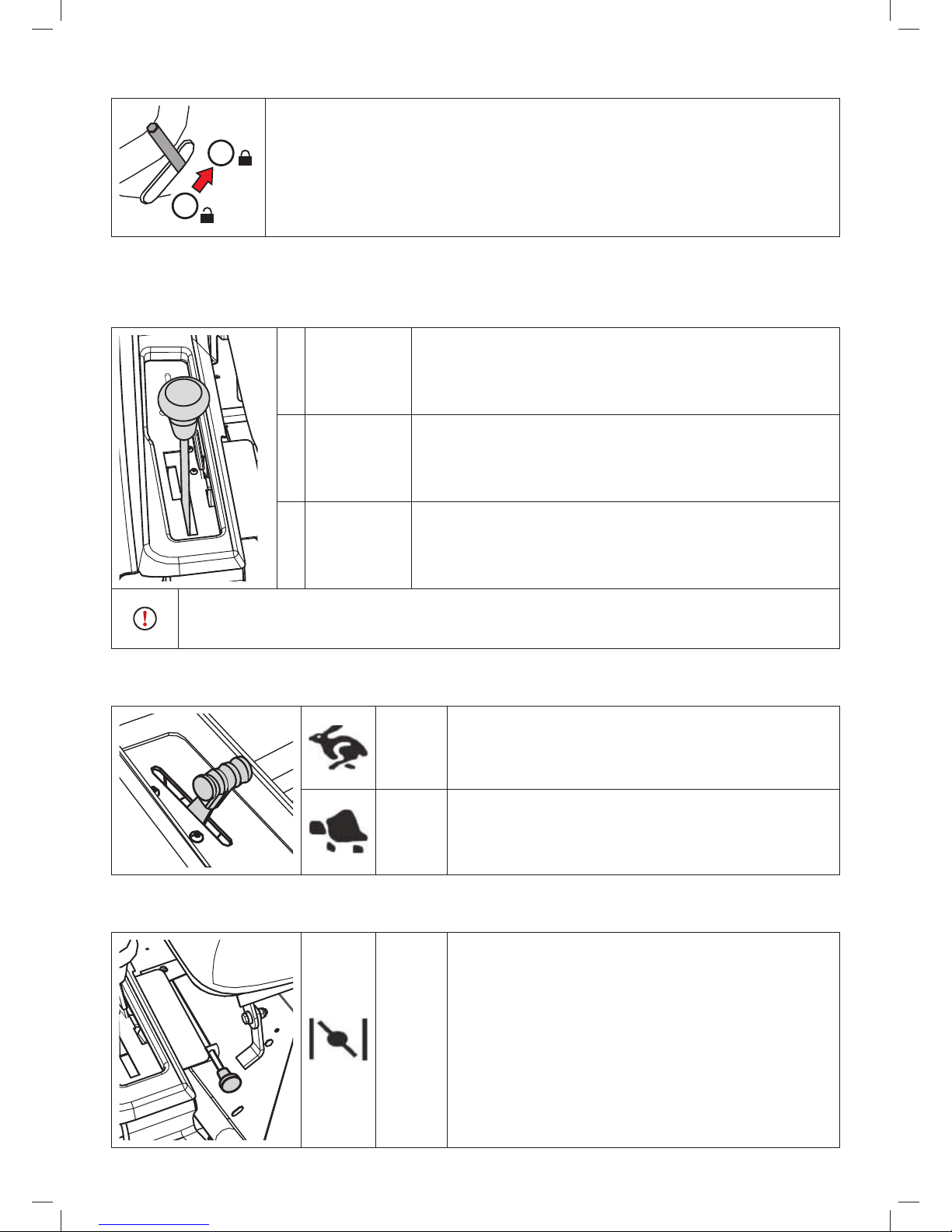
(3) PARKING BRAKE LEVER
1
2
The parking brake has two positions. In position (1) the brake is not active,
after shifting to position (2) while stepping down on brake pedal the parking
brake is activated (will brake).
Stepping on the brake pedal will deactivate the parking brake and the lever will
automatically be released and shift to position (1).
(4) TRAVEL DIRECTION LEVER
It controls the power supplied to the rear wheels and regulates the speed of the machine in both
directions. In the basic setting it is equipped with a mechanical cruise control function, which is
automatically deactivated by pressing the brake pedal.
F
Forward
travel
Moving the lever closer to the letter F corresponds to a
higher speed and vice versa
N Neutral The machine is still
R
Reverse
travel
Moving the lever closer to the letter R corresponds to a
higher speed and vice versa
Changing the travel direction from forward to reverse or from reverse to forward
is only possible after stopping the machine. When the brake pedal is stepped on
the gear stick automatically shifts to position „N“.
(5) THROTTLE LEVER
Serves to regulate the engine speed. It has the following three positions:
MAX Maximum engine speed
MIN Minimum engine speed (idle)
(6) CHOKE
For starting a cold engine:
CHOKE Starting a cold engine
Page 24
24
(7) CRUISE CONTROL DISENGAGE LEVER
This lever disengages the mechanical cruise control function and so it is possible to travel with the
machine very accurately at a slow speed.
Do not disengage the cruise control when travelling at a high speed!
0 Cruise control is engaged
1 Cruise control is disengaged
(8) MOWING DECK RUN DOWN INDICATOR
This indicator indicates when the mowing deck is on and running down.
Light is on The mowing deck is activated
Flashing
The mowing deck is deactivated, but the blades are still rotating (the
indicator flashes for approx. 10 seconds)
(9) MOWING DECK ACTIVATION SWITCH
Pulling out the activation switch upwards activates the mowing deck. Pushing it down deactivates the
mowing deck.
DEACTIVATED
Deactivation of the mowing deck / the mowing deck is
deactivated.
ACTIVATED Activation of the mowing deck
Page 25
25
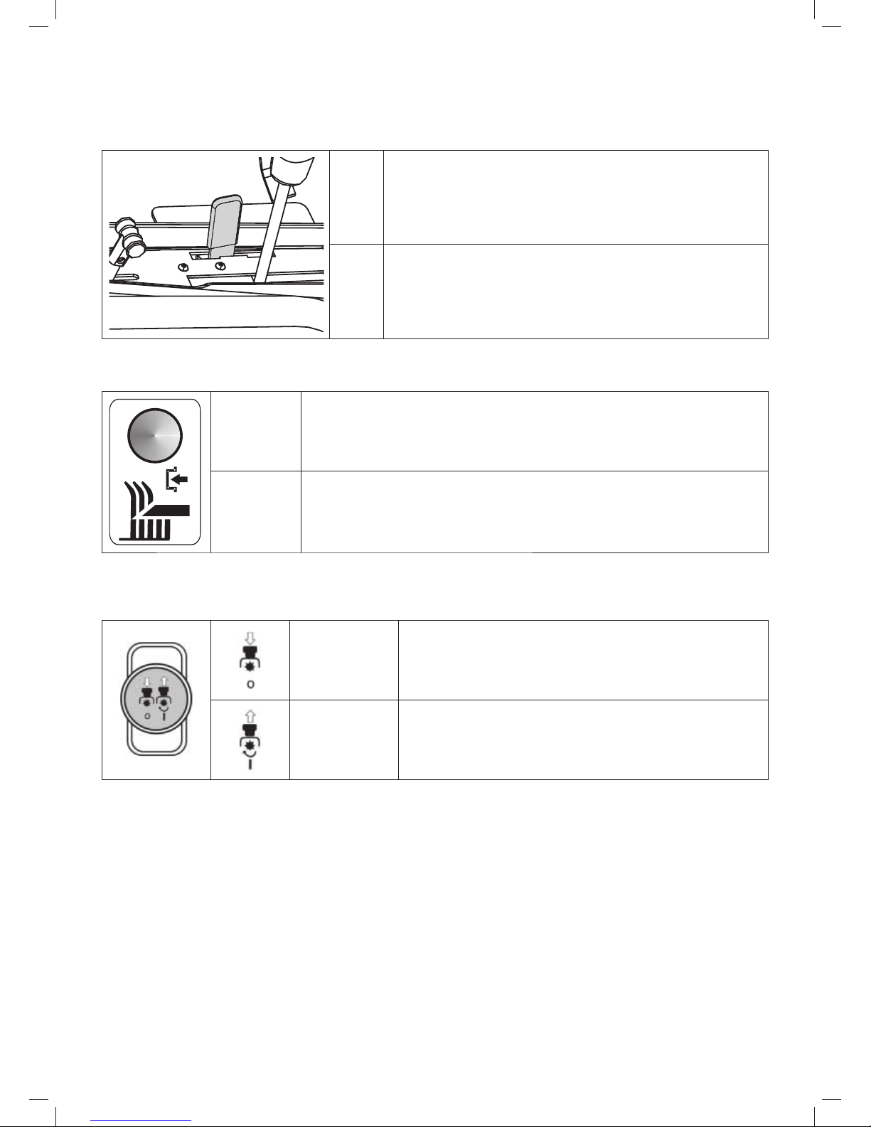
(10) MOWING DECK ELEVATION ADJUSTMENT LEVER
The lever serves to set the elevation height of the mowing deck from the ground.
The lever has 4 work positions (50 - 60 - 75 – 100 mm), where the
corresponding mowing height is 5 to 10 cm. The higher the number
of the lever position, the higher vegetation height remains after
mowing.
There is also 1 transport position, which is 120 mm above the
ground. When the lever is set to the transport position it is not
possible to activate the mowing deck as a safety switch is built into
this position.
When travelling without mowing the lever must be set to the transport position!
The mulching function can be improved by using a special accessory, a so-called „mulching
set“, which is supplied separately as a special accessory for mowing maintained lawns.
(11) BY-PASS LEVER – FREE MOVEMENT OF THE REAR WHEELS
The by-pass lever serves to disengage the transmission for the rear wheel drive and is used to push or
pull the machine without using the engine. The lever is located on the rear side of the machine and has
the following two positions:
Position Rear wheel drive Use
(0) DISENGAGED
Lever is extended - for pushing the
machine
(1) ENGAGED
Lever is inserted - for driving the
machine
ATTENTION! On the AC 92-23 4x4 machine the lever is used primarily for bleeding the
hydrostatic system. Due to the high demands on equipment, have this procedure performed
by a specialised service centre.
The machine must not be used (gear shifted into drive) if the by-pass lever is in the
disengaged position - there is a danger of damage to the transmissions!
Page 26
26
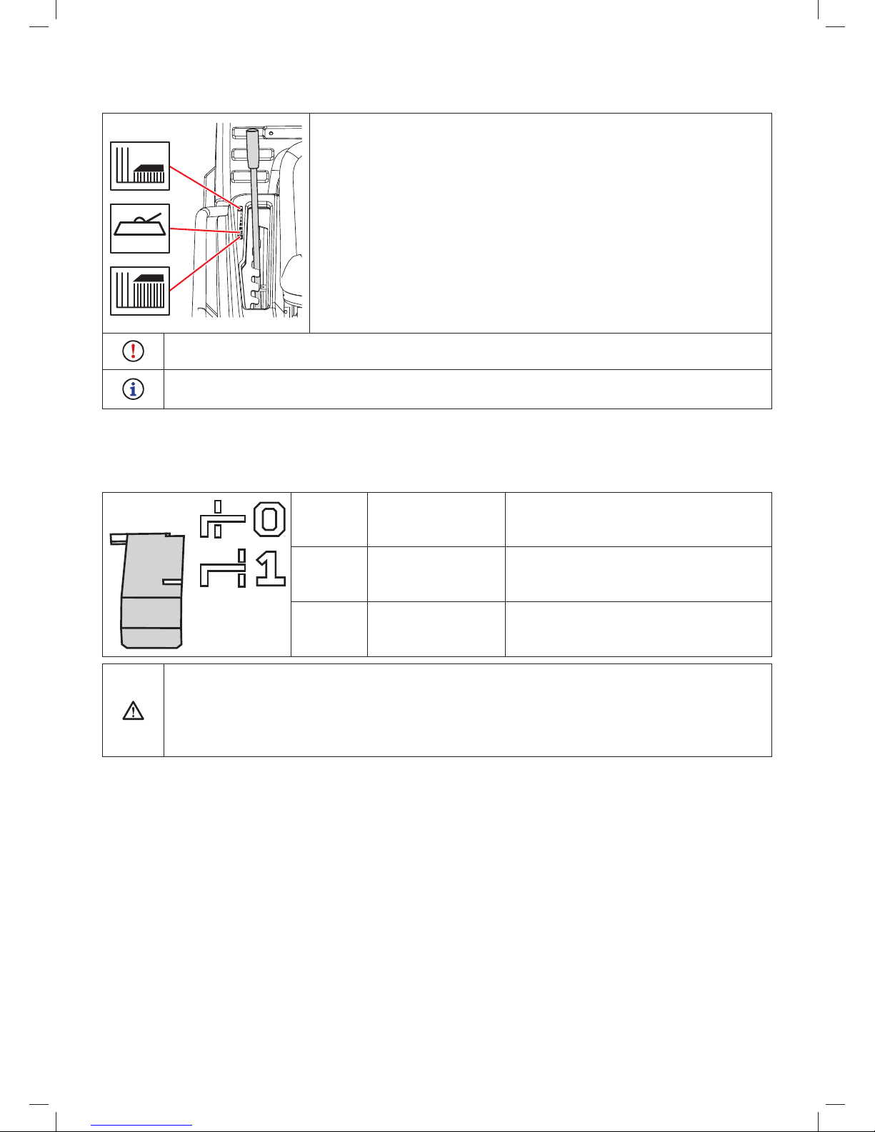
(12) MOTOR HOURS COUNTER
The motor hours counter implicitly displays the total number of
motor hours. By pressing the Mode button you gradually switch
between the following maintenance functions:
TMR 1 - individual trip counter. The value is reset by
holding down the Mode button for 6 seconds.
OIL CHG - oil change. The function has two oil change
intervals. The first is after 5 hours (oil
change after the engine has run itself in) and
is shown only once. The second is after 25
hours (standard oil change).
AIRFILTER SVC - cleaning or changing the air filter. The interval
is set to 50 hours.
Two hours before the set interval has elapsed the display will
show a message lasting 10 seconds.
After the interval has elapsed the display will show the message
NOW.
Any of the above mentioned alarms can be reset by holding
down the Mode button for 6 seconds.
Tampering with the counter will void the warranty – the motor hours connection is equipped
with a tamper seal.
Immediately contact your service centre if the motor hours counter malfunctions.
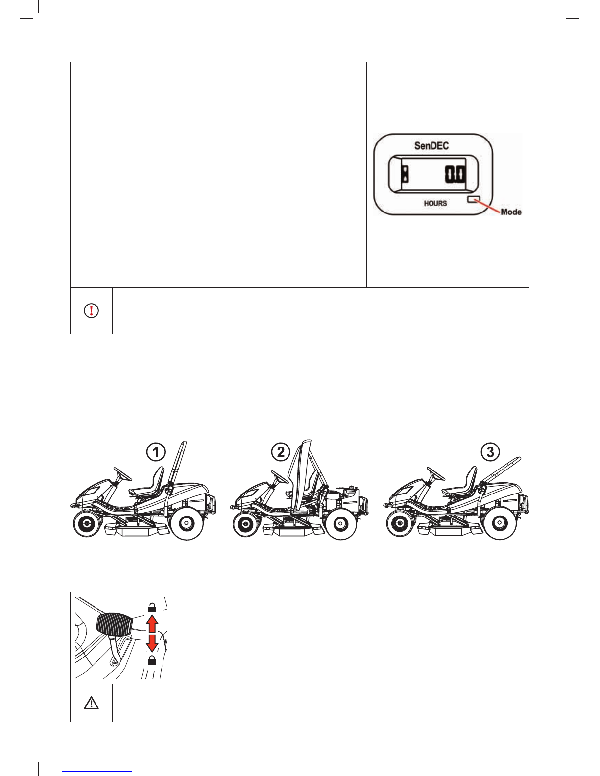
(13) FOLDING FRAME
The folding frame is intended to prevent the machine from rolling over by 180° if for any reason it loses
stability and rolls on to its side. Under no circumstances does the protective frame serve as safety /
protection feature for the operator! The folding frame has 3 positions:
1. Work
2. Maintenance
3. Auxiliary for handling the machine
The individual positions are set using quick coupler levers on the sides of the frame.
(14) DIFFERENTIAL LOCK PEDAL
The pedal is used only if necessary and only when driving directly forward. It has two positions:
(
)
(
)
When the pedal is pushed down the lock is engaged.
When the pedal is released the lock is automatically disengaged.
Use the lock only when driving directly forward and only if necessary (loss of
traction). Never use the differential lock when changing travel direction. Otherwise
there is a risk of serious damage to the transmission!
Page 27
27
5. OPERATION AND HANDLING OF THE MACHINE
Information which it is good to know before the riding mower is first turned on:
The riding mower is equipped with safety contacts, which are connected by a switch
located under the seat.
The motor will automatically shut off when the driver leaves the seat and the machine is
not secured using the parking brake.
The engine can only be started when the mowing deck is turned off and the mowing deck
elevation adjustment lever is in the transport position.
5.1 CHECKS PRIOR TO STARTING UP THE MACHINE
Before starting up the riding mower check the following:
Oil level in the engine (
3.4.1)
Battery charge level (
3.4.2)
Fuel level (
3.4.3)
Air pressure in the tyres (
3.4.4)
That the by-pass lever is in position “1”
5.2 STARTING UP THE ENGINE
a) Set the mowing deck elevation adjustment lever to the transport position.
b) Move the mowing deck activation switch to position “DEACTIVATED”.
c) Move the travel direction lever to position “N”.
d) Move the throttle lever to maximum engine speed.
e) Pull out the choke.
f) Start up the engine by moving the ignition key to position “Start engine”. After starting the engine,
release the key. The key will automatically return to the position “Ignition on”
As soon as the engine starts up, release the ignition key. The duration of starting up
must not exceed 10 seconds, otherwise there is danger of damage to the switch!
Never use fixed external starters to start the machine. This could damage the
electrical wiring. It is possible to connect a higher capacity 12V battery.
g) Push in the choke.
h) Slowly move the throttle lever to the idle position (reduce the engine speed).
Allow the engine to run several minutes before turning on the mowing deck.
Never leave a started engine running in a closed or poorly ventilated area. Exhaust fumes
contain gases that are harmful to your health.
Keep your hands, legs and clothing away from moving parts and the exhaust.
5.3 TURNING OFF THE ENGINE
a) Move the throttle lever to position “MIN”.
b) If the mowing deck is activated, deactivate it by pushing down the switch.
c) Turn off the engine by moving the key to position “STOP” and take the key out of the ignition.
If the engine is overheated, allow it to run for a while at minimum speed.
Page 28
28
Never stop the engine by merely getting off the seat, while leaving the key in the
ignition in the position “ON” as this may result in an electrical defect.
Always turn the key to the “OFF” position and remove it from the ignition. This will
prevent an undesirable start up of the machine by an unauthorised person or children.
Before turning off the ignition lower the engine speed to slow for the event of self-
ignition. Not following this instruction may result in damage to the engine and exhaust.
Never disconnect the battery cables while the engine is running! This could damage
the engine regulator.
5.4 ACTIVATING AND DEACTIVATING THE MOWING DECK
5.4.1 ACTIVATING THE MOWING DECK
Move the throttle lever to position “MAX”.
Using the mowing deck elevation adjustment lever set the position of the mowing deck and thereby
the mowing height.
Set the mowing deck activation switch to position “ACTIVATED”.
Conditions for activating the mowing deck:
- the driver is sitting in the seat of the machine
- the mowing deck elevation adjustment lever is in the transport position
5.4.2 DEACTIVATING THE MOWING DECK
Deactivate the mowing deck by pushing down the activation switch.
If the driver leaves the seat, the engine will automatically shut down and thereby the rotation
of the mowing blades also.
However, never turn off the mowing deck by simply leaving the seat. If you do not move the
key in the ignition from the position “ON” to position “STOP”, then a part of the electrical
installation will still be live and this may result in it being damaged. Also the motor hours
counter remains activated.
5.4.3 SETTING THE HEIGHT OF THE MOWING DECK FOR MOWING
If you wish to set the mowing deck higher off the ground, move the mowing
deck elevation adjustment lever upwards to position 50 or 100. This position is
used to mow high and wet vegetation to a height of 5 or 10 cm.
If you wish to set the mowing deck closer to the ground, move the mowing deck
elevation adjustment lever downwards to position 50 or 60. This position is used
to mow level and maintained areas to a height of 5 or 6 cm.
5.5 DRIVING THE MACHINE
General warnings before driving:
Make sure that the parking brake is disengaged. The parking brake must not remain in position “2”
(
4.2.1 (3)). Stepping down on the operating brake automatically disengages the parking brake.
The by-pass lever must be set to position “1”, i.e. by-pass of the drive must be activated.
When travelling to the mowing location, the mowing deck must be deactivated and raised in the
transport position.
Page 29
29
When travelling over obstacles higher than 8 cm (kerbs, etc.) it is necessary to use ramps to
avoid damaging the mowing deck and the gear box.
Avoid hard impacts of the front wheels against rigid obstacles, this may result in damage to the
front axle, particularly when the machine is travelling at a high speed.
5.5.1 TRAVELLING FORWARD / REVERSING
While accelerating slowly move the gear lever to the required direction of travel, i.e. to travel forward
to position “F”, and to reverse to position “R”.
If you wish to reduce your travelling speed, move the gear lever away from the direction of travel. To
increase the travelling speed move the gear lever towards the direction of travel.
Changing the direction of travel forward-reverse is possible only after moving the
gear lever to position “N” and leaving the lever in this position for a short while. If
the machine is not still, there is a danger of damaging the transmission.
Never use the travel direction lever and the brake at the same time – this may damage the
transmission.
5.5.2 STOPPING TRAVEL
The movement of the machine forward / reverse is stopped by stepping down on the brake pedal
and the gear stick will automatically return to the position “N”. The braking distance is shorter than
1.5m.
In the event that cruise control is activated and the brake pedal is stepped on, it automatically
moves to the neutral position. The braking distance is shorter than 2 m.
The machine can only be stopped by gradually moving the travel direction lever to position
“N” and then gradually stepping on the brake pedal.
Never use the travel direction lever and the brake at the same time – this may damage the
transmission.
5.5.3 TRAVELLING SPEED AND MOWING GRASS
It generally applies that the wetter, higher and more dense the grass is, the lower the
travelling speed that should be used. When the machine is travelling too fast or higher demands
are place on it, the blade rotation speed declines as does the mowing quality. Under such conditions
always set the engine to maximum power.
If the grass is very high, it is necessary to mow it several times. First mow at maximum height
and with narrower mowing coverage width if necessary. The second run can then proceed at the
required mowing height.
We recommend mowing in the parallel or cross direction. Covering the previous coverage of the
machine increases the effectiveness of the blades and will improve the appearance of the mowed
area.
When travelling over uneven terrain the travelling speed may fluctuate.
Page 30
30
5.5.4 TRAVELLING ON A SLOPE
Riding mowers models AC 92-18 and AC 92-20 can work on
slopes with an incline of up to 18° (32%).
With the AC 92-23 4x4 machine it is possible in the
longitudinal direction of the machine, i.e. in the direction up
and down, however not along the contour, to travel over local
uneven terrain up to a maximum incline of 20°.
When working on a slope it is necessary to adhere to the
following fundamentals:
Pay increased attention when travelling on a slope.
Always use a lower travelling speed and regulate the
travelling speed by moving the travel direction lever.
Only travel perpendicular to the contour, i.e. up and down.
Travelling in the direction of the contour is possible with
extra attention only when turning the machine. If at all
possible, avoid travelling along the contour.
When turning ensure that a wheel does not drive over an
elevated obstacle (rock, tree root, etc.)
Travel slower when trav elling down a slope or over obstacles.
Pay special attention when turning and turning around on
slopes.
If you stop on a slope, always use the parking brake.
Right
AC 92-18
AC 92-20
AC 92-23
4x4
Max 18
(32 )
o
%
Max 20
o
(32 )%
Wrong
When overloading the machine by travelling on slopes over 18° (20°) there is a risk of
serious damage to the gear box. The manufacturer is not responsible for damage caused in
this way.
Page 31

31
6. MAINTENANCE AND ADJUSTMENT
Properly performed regular maintenance and inspection of the riding mower helps to increase its
problem-free operating lifetime. Worn or damaged parts must be replaced in time. When replacing
parts use only original spare parts, using non-original parts may damage the machine, endanger the
health of the driver or other persons and during the warranty period it voids the warranty. To order
spare parts always contact the machine’s manufacturer or an authorised service centre.
6.1 OVERVIEW OF CHECKS AND MAINTENANCE
PART
INTERVAL
NOTE
Before every use
After every 50 hours
of operation or 1x
per year
Every 100 hours or
1x per year
BATTERY ---
Check the level of the
electrolyte
--- Check the connection
FUEL FILTER --- --- Replacement ---
BLADE HOLDER Check --- --- ---
ELECTRICAL
CIRCUIT
Check safety switches Check cable bundles --- ---
HYDRAULIC CIRCUIT Check for leaks --- --- ---
ENGINE COOLING
Remove grass from
the engine grill and
from the exhaust
Cleaning --- ---
DRIVE V-BELT
Check for wear,
tension
--- --- ---
MOWING V-BELT
Check for wear,
tension
--- --- ---
MOTOR OIL Check the level, fill up Oil change --- ---
V-BELT TENSIONING
MECHANISM
Check if working Check condition --- ---
OIL IN THE
HYDRAULIC CIRCUIT
--- --- ---
Replacement after
200 hours of operation
OIL FILTER --- --- Replacement
OIL FILTER OF THE
TRANSMISSION
--- --- ---
Replacement after 200
hours of operation
PARKING BRAKE Check if working Check mechanism ---
TYRES
Check pressure and
condition
--- ---
Front 150kpa
Rear 80kpa
CONTROL ELEMENTS --- Check --- ---
RUBBER COVERS Check condition --- --- ---
FRONT DRIVE AXLE.
(FOR MODEL
AC 92-23 4x4)
Check condition and
fastening of all ball
joints and check the
steering connection
rod
--- ---
The ball joints must
have minimum
looseness.
The connecting rod
must not show signs of
damage (cracks)
FRONT AXLE
Check the condition of
the joints and wheels
Lubrication of vertical
joints
--- ---
GEAR BOX Check for leaks
Check condition of
pulley
Check oil level
Oil SAE 10w-40
5w-50 (4x4)
GEAR STICK Check if working Check belt tension --- ---
STEERING --- Check if working --- ---
SPARK PLUGS --- ---
Clean and adjust or
replace
---
Page 32

32
PART
INTERVAL
NOTE
Before every use
After every 50 hours
of operation or 1x
per year
Every 100 hours or
1x per year
FAN, ENGINE
RADIATOR FINS
--- --- Cleaning ---
ALL PULLEYS
Check condition and
working order
--- --- ---
MOWING HEIGHT
Check, lubrication of
pins
--- --- ---
AIR FILTER Cleaning Replacement
Depending on nature
of use - more often
MOWING BLADES
Check condition and
fastening
--- --- ---
MOWING DECK
Check condition and
fastening
--- --- ---
For the replacement of all parts or for repairs, which require disassembly and which are not
described in this user’s manual, contact your seller or an authorised service centre. Contact
your seller also for the following adjustments and maintenance:
• adjustment of the electromagnetic clutch
• adjustment of the brake
• adjustment of the engine
• replacement of V-Belts
• bleeding of the hydraulic circuit (for model AC92-23 4x4)
• adjustment of the front drive axle (for model AC92-23 4x4)
• other problems with the hydraulic circuit (for model AC92-23 4x4)
• in the event of other difficulties
6.2 DAILY CHECKS AND MAINTENANCE
Before starting any maintenance or repair works, thoroughly reacquaint yourself with all
instructions, restrictions and recommendations in this user‘s manual.
Always remove the key from the ignition and disconnect the spark plug cables before
performing any cleaning, maintenance or repairs.
When working use suitable work clothing and work footwear. Use suitable gloves when
handling a mowing blade or for activities where there is a risk of cuts.
Avoid spilling fuel, oils or other harmful substances.
Do not perform any major repairs if you do not have the necessary tools and a
good knowledge about repairs of combustion engines!
Dispose of used oil, fuel or other hazardous substances and materials in accordance
environmental protection regulations in force.
Page 33

33
6.2.1 BEFORE STARTING WORK
CHECK TYRE PRESSURE
Maintain the prescribed tyre pressure and check it regularly. Maintaining the prescribed tyre pressure
is important for even mowing. Different pressure values may cause difficulty in driving, or even loss of
control over the machine.
Pressure in the front tyres: 150 kPa
Pressure in the rear tyres: 80 kPa
The difference between the individual tyres may be ± 10 kPa.
CHECK THE OIL LEVEL IN THE ENGINE
Park the riding mower on a horizontal surface. Open the hood and unscrew the cap of the filling opening.
Screw out the oil dipstick, wipe it dry, reinsert it and screw in. Then again screw it out and take the oil
level reading.
The oil level must be between the two marks on the dipstick. If it is not, fill up with motor oil so that it
reaches the “FULL” mark.
Further details about checking and filling of oil are included in a separate user‘s manual
supplied by the engine‘s manufacturer.
CHECK CABLES AND BOLT CONNECTIONS
Visually inspect the condition of cables and manually check the tightness of bolt connections.
CHECK WORKING ORDER OF BRAKES
Check that the brakes work properly. Proceed as follows:
Park the machine on an even surface and turn off the engine.
Step on the brake pedal and engage the parking brake.
Using the by-pass lever disengage the rear wheel drive.
Try to push the machine forward. If the rear wheels rotate, then the brakes need to be serviced.
Contact an authorised service centre to have them adjusted.
6.2.2 AFTER FINISHING WORK
SETTING UP THE MACHINE
After finishing mowing elevate the mowing deck to the highest position and disable the drive for the
mowing blades.
Turn off the ignition, step on the brake pedal and secure the machine in position with the parking brake.
CLEANING THE MACHINE
Remove all dirt and grass remains from the surface of the tractor.
Also remove grass, dust and other flammable materials from the edge of the exhaust.
CLEANING THE MOWING DECK
The mowing deck must be carefully cleaned after every use, namely the inside walls of the deck. Use
a scraper, spatula or a current of water for cleaning. Proper maintenance and treatment of the mowing
deck improves work quality and the machine’s lifespan. Proceed as follows:
Secure the machine against movement.
Elevate the mowing deck to the transport position.
Lift (tilt out) the protective metal cover on the right side of the chamber. Clean out the entire area of
the mowing deck.
While cleaning also check the condition of the blades (
6.3.6).
Page 34

34
WASHING THE MACHINE
We do not recommend cleaning the machine using pressurised water! If despite
this you do clean in this way, ensure that water does not enter the carburettor, air filter,
ignition, exhaust, battery and other electrical components.
Never direct the water current at the ball bearings (bearings in the blade holder, wheels) or
on to parts in which there is oil (oil filter, filler neck, etc.)
Before washing, park the machine on a suitable even surface.
Plastic parts on the machine:
- clean using a sponge and soapy water
6.3 REGULAR CHECKS, MAINTENANCE AND ADJUSTMENT
6.3.1 BATTERY
Correct and regular maintenance of the battery will extend its lifespan. Therefore regularly check its
condition according to the manual supplied by the battery’s manufacturer.
Keep the battery contacts clean. If dirt accumulates on them, or they are rusty, clean them according
to the recommendations of the battery’s manufacturer. Interruption of the circuit caused by the
oxidation of the contacts may lead to the malfunction of the recharging function of the engine!
Regularly check the condition of the electrolyte. The level must be in the
range MIN - MAX. In the event of filling up the electrolyte, use only distilled
water.
A flat battery needs to be recharged as soon as possible, otherwise its cells may be irreparably
damaged.
It is always necessary to charge the battery before:
- first use
- when not planning on using it for a long time
- before starting up after a longer break
If it is necessary to replace the battery, always use a battery of the same size and type.
Further details about checking and maintaining batteries are included in a separate user‘s
manual supplied by the battery‘s manufacturer.
6.3.2 ENGINE
CHANGING OIL
Before changing the oil, prepare a container with a volume of at least
2 litres. So that all the oil flows out of the engine we recommend that
you place something (e.g. wooden blocks) under the side opposite the
drain screw. Drain the oil while it is still warm.
Unscrew the filler opening of the oil so that the oil flows better and
faster out of the engine.
Unscrew the drain screw and allow the oil to fully flow out into the
prepared container.
Screw the drain screw back on and fill the engine with the correct
amount of the recommended oil (
User’s manual for the engine)
and close the oil filler cap.
Use the dipstick to check the correct oil level. If necessary fill up the
oil so that the oil is at the correct level.
Page 35

35
Further details about replacing oil as well as its type and amount are included in a separate
user‘s manual supplied by the engine‘s manufacturer.
If you come into contact with used oil, we recommend that you thoroughly wash your hands
with soap and water.
Dispose of used oil according to environment protection laws. It is appropriate to deliver
the oil in a closed container to a used oil collection point. Under no circumstances should
dispose of the used oil with other waste or pour it down the drain, on to waste or on the
floor.
MAINTENANCE OF THE AIR FILTER
Never allow the engine to run without an air filter. This rapidly wears out the engine.
Maintain the air filter according to the instructions contained in the user‘s manual for the
engine supplied by its manufacturer.
MAINTENANCE OF THE SPARK PLUG
For the engine to run perfectly the spark plug must be correctly set and clean from deposits.
Always use only the spark plug specified by the engine’s manufacturer!
If the engine was running shortly before the inspection or replacement, then the spark plug
will be very hot. So be very careful not to burn yourself.
Take off the spark plug cable and remove the spark plug using a wrench
key.
Visually inspect the exterior appearance of the spark plug. If the spark
plug is visibility significantly worn out or if the insulator is cracked or it is
peeling, it is necessary to replace it.
If the spark plug is soiled or only slightly worn, it is necessary to carefully
clean it with a suitable wire brush (copper).
Using a gauge measure set the distance of the electrodes (
User’s
manual for the engine).
After performing maintenance on or replacing the spark plug, pull it tight in
position. An incorrectly tightened spark plug heats up significantly and may
cause serious damage to the engine.
Check, maintain and replace spark plugs according to the instructions contained in the
user‘s manual for the engine supplied by its manufacturer.
REPLACEMENT OF THE FUEL FILTER
Never allow the engine to run without a fuel filter. This rapidly wears out the engine.
Replace the fuel filter according to the instructions contained in the user‘s manual for the
engine supplied by its manufacturer.
MAINTENANCE OF THE ENGINE COOLING
Before each use or during work check that the grill on the engine is not clogged with grass remains or
other objects. Clean the grill if necessary!
After every 100 hours of operation or once a year remove the fan cover and clean soiled and clogged
areas and the cooling fins of the engine. This will avoid the engine from overheating or being damaged.
Clean more frequently if necessary.
6.3.3 REPLACING LIGHT BULBS
Light bulbs are seated in a holder and are accessible after lifting the hood.
Turn the rotating lock holding down the front hood, remove the light bulb by sliding it out of the
holder, e.g. using a screwdriver and reinsert. Return the lid of the hood
The light bulb type and its rating are specified in the spare parts catalogue.
Page 36

36
6.3.4 REPLACING A FUSE
If a fuse is damaged the engine will immediately shut off, the mowing
deck will stop and all indicator lights on the dash board will turn off.
In this case it is necessary to find the faulty fuse and replace it with
a new one. Under no circumstances should you replace a faulty fuse
with a fuse that has a higher current rating!
Release the screw holding down the front hood, lift the hood and
remove the protective fuse cover.
Remove the old fuse and insert a new fuse with the same rating as
the initial fuse, i.e. 15A or 5A.
If even after replacing the fuse the engine or the mowing deck will not work, contact an
authorised service centre.
Under no circumstances should you attempt to remove the control unit of the
electrical system!
6.3.5 LIFTING THE MACHINE
If you wish to lift the riding mower, use a jack and supports.
Proceed as follows:
Place the jack underneath the gear box on the rear axle and lift the rear part of the machine.
Insert two supports underneath the ends of the axles from the inner side of the rear wheels.
Lift the front part of the machine and insert two supports under both ends of the front wheel axles.
Never lean the machine to the side where the carburettor is located. Oil could enter the air
filter!
6.3.6 MOWING DECK – CHECKING AND MAINTENANCE OF THE MOWING BLADES
Before each use of the riding mower check the condition of the blades (damage, wear, condition of the
cutting edge). If the blades are blunt, bent or broken it will negatively affect mowing quality. Damaged
blades are very dangerous.
A part of the material could break off and be deflected from the work area of the machine.
Whenever handling the mowing blades, always use heavy-duty work gloves.
REPLACING BLADES
If due to frequent use the blades are worn or damaged, they cannot be balanced or sharpened properly,
it is necessary to replace them immediately.
The blades are sharpened from both sides so in the event that one side is blunt, it is possible
to turn the blade around.
Page 37

37
Always completely replace both blades and use new M16 lock nuts for attachment. This will
ensure that the mowing deck is balanced and that the blades are securely attached. Proceed as follows:
Turn off the engine and take the key out of the ignition.
Secure the machine against movement.
Elevate the mowing deck to the transport position.
Open the metal cover on the right side of the mowing
deck chamber.
Screw out the M16 lock nut.
Take off the fasting bolt, O-ring and blade.
Install a new or sharpened blade proceeding in the
reverse sequence.
Use new, unused M16 lock nuts.
Before replacing the second blade turn the blade holder
with your hand by 180°.
Replace the second blade following the same
procedure as for the replacement of the first blade.
When reinstalling the blades, ensure that they are correctly
fastened and secured in place!
70 10 Nm
70 10 Nm
+
275 25 Nm
275 25 Nm
+
SHARPENING THE BLADES
The mowing blades must be sharp, statically balanced and straight. Blunt, incorrectly sharpened or
damaged mowing blades cause grass to be torn out of the ground, damage to lawns and mediocre
collection of mowed grass in the grass catcher.
If the blades are merely blunt and do not exhibit any other damage, then they may be sharpened. After
sharpening the pair of blades must be balanced. Balancing will prevent vibrations of the mowing deck.
The weight difference between the individual blades may not exceed 2g. During replacement
always also check the wear on the distance sleeves and mounting bolts, ensuring they are in perfect
condition. If serious damage to the mowing deck is discovered it is necessary to have the machine
thoroughly inspected at an authorised service centre.
Always use a new, unused M16 lock nut. Never reuse a lock nut that has already
been used, because safe attachment of the blade cannot be guaranteed!
Do not repair a blade that is deformed or otherwise damaged, replace it
immediately.
Whenever handling the mowing blades, always use heavy-duty work gloves.
Sharpening procedure:
Turn off the engine and take the key out of the ignition.
Secure the machine against movement.
Elevate the mowing deck to the transport position.
Open the metal cover on the right side of the mowing
deck chamber.
Screw out the M16 lock nut.
Take off the fasting bolt, distance sleeve and blade.
Remove the second blade in the same way as the first.
Clean both blades.
First sharpen with a grinder and then with a file.
Do not sharpen directly on the mowing deck.
Page 38

38
Install the sharpened blade proceeding in the reverse sequence.
Use new, unused M16 lock nuts.
Before replacing the second blade turn the blade holder with your hand by 180°.
6.3.7 MOWING DECK - CHECKING THE DRIVE PULLEY OF THE DECK
Before every use of the machine, check the
fastening bolt of the pulley. The bolt should
be pulled tight with a torque of 80 Nm.
The pulley is accessible after lowering the
mowing deck to the lowest position.
80 Nm
6.3.8 CHECKING AND ADJUSTING THE DRIVE BELT
When working on various parts of the machine‘s drive always turn off the engine and take
the key out of the ignition.
Regularly check the wear and tension of V-belts and
the tensioning mechanism.
The drive V-belts (travel and mowing) are automatically
tensioned by a spring and a pulley. Before starting
work or at least after every 50 hours of operation
check the wear on the V-belts and the working order
of the tensioning mechanism.
Adjust the position of the drive belt tensioning pulley
using adjusting nuts.
Distance A = 60±2 mm.
Distance B = 78 mm (set the mowing deck elevation
adjustment lever to the second last position)
B
B
A
A
When attaching a new belt pay special attention when working with the machine because
the belt is not yet sufficiently run-in.
6.3.9 REPLACING BELTS
Replacing drive belts is a relatively demanding operation, which needs to performed by an authorised
service centre.
6.3.10 ADJUSTING THE CRUISE CONTROL LEVER
If cruise control is activated and the drive lever is independently returning to position “N”, then it is
necessary to adjust the cruise control lever. Have this task performed at a specialised service centre.
6.3.11 REPLACING WHEELS
Before replacing one of the wheels, park the tractor on a horizontal and rigid surface, turn off the
engine and remove the key from the ignition. Secure the machine against movement. Do not replace
the wheel if the machine is not sufficiently secured in the elevated position!
If you do not have suitable tools or the necessary knowledge, contact your seller.
Page 39

39
Perform the replacement as follows:
Place the jack underneath the front or rear bumper near to the wheel
which you wish to replace. For model AC 92-23 4x4 – always place the jack
against the frame - do not lean it on the transmission, this could damage it!
Keep lifting the machine until the wheel, which you wish to change no
longer touches the ground.
Remove the protective cover from the wheel.
Using a suitable screwdriver remove the retaining ring and remove the
washer.
Pull the wheel off the shaft.
When reattaching the wheel proceed in the reverse sequence to its removal. Before attaching the
wheel clean all parts and lightly grease the shaft with a plastic lubricant. Especially for wheels on the
rear axle this lubrication is essential for the subsequent removal of the wheel. In the event
that lubrication is not performed the subsequent attachment may be very difficult.
When attaching the rear wheel pay attention to the mutual alignment of the pin on the shaft and the
groove on the wheel.
Finally check the tyre pressure.
6.3.12 REPAIRING A TYRE PUNCTURE
The machine is equipped with tubeless tyres. In the event of a puncture have it repaired at a specialised
tyre repair shop or at an authorised Seco machine service centre.
6.3.13 MAINTENANCE OF THE HYDROSTATIC TRANSMISSION
For the reliable operation of the transmission it is necessary to maintain the correct oil
level. In the event of problems with the transmission immediately seek the help of an
authorised service centre, there is a risk of serious damage to the transmission.
6.4
Machine
model
Oil type Oil level
AC 92-18(20) SAE 10W-40, API CD At least to half the height of the equalisation tank
AC 92-23 4x4 SAE 5W-50 synthetic oil
Between the marks on the dipstick in the tank cap
(total oil volume in the hydraulic system is 6l)
In the event of problems with the transmission immediately seek the help of an authorised
service centre, there is a risk of serious damage.
Page 40

40
6.3.14 OVERVIEW OF THE TIGHTENING TORQUE OF BOLT CONNECTIONS
Steering: Torque
M14 nut of steering segment 92 - 132 Nm
M14 nuts of the angle pins on the steering 60 - 83 Nm
Securing of pins on the front axle SC 2x4 40 - 50 Nm
Engine:
Bolt of the electromagnetic clutch 60 - 70 Nm
Mowing:
M10 nut of the tensioning mowing pulley 33 - 48 Nm
M20 nut of the blade holder 250 - 300 Nm
M16 nut securing the blades to the blade holder 150 - 200 Nm
M12x30 bolt on the mowing pulley 60 - 80 Nm
Driving controls:
M10 nut on the drive pulley SC 2x4 24 - 30 Nm
M10 nut on the drive pulley SC 4x4 35 - 45 Nm
When lock nuts are removed and then returned they need to be replaced with new
ones.
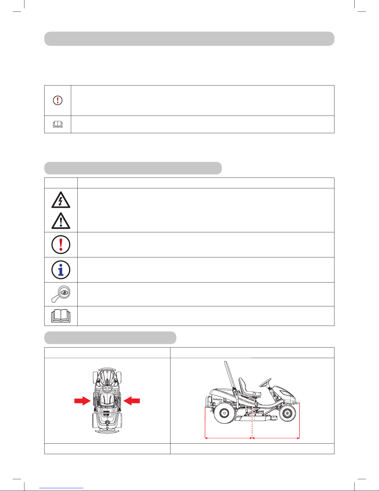
6.4 LUBRICATION
Lubricate the machine according to the following lubrication diagram.
Ball bearings of the tension pulleys, guide pulleys and bearings on the mowing deck are self-lubricating.
Before putting the machine out of service for an extended period, thoroughly lubricate all places shown
on the diagram. Namely the half axle of the front and rear axle (it is necessary to remove the rear
wheels).
6.4
Symbol Explanation
Plastic lubricant
Oil SAE 30
Interval in hours
Plastic lubricant is used to lubricate:
steering segment - using a lubricating nipple
wheel turning pin - using lubricating nipples
mowing deck lifting arms - using a lubricating nipple
tensioning pulley - remove, lubricate
central front axle pivot pin - using a lubricating nipple (model AC 92-23 4x4 is equipped with self-
lubricating sliding sleeves)
angle joints connecting the steering draw bars - remove, lubricate
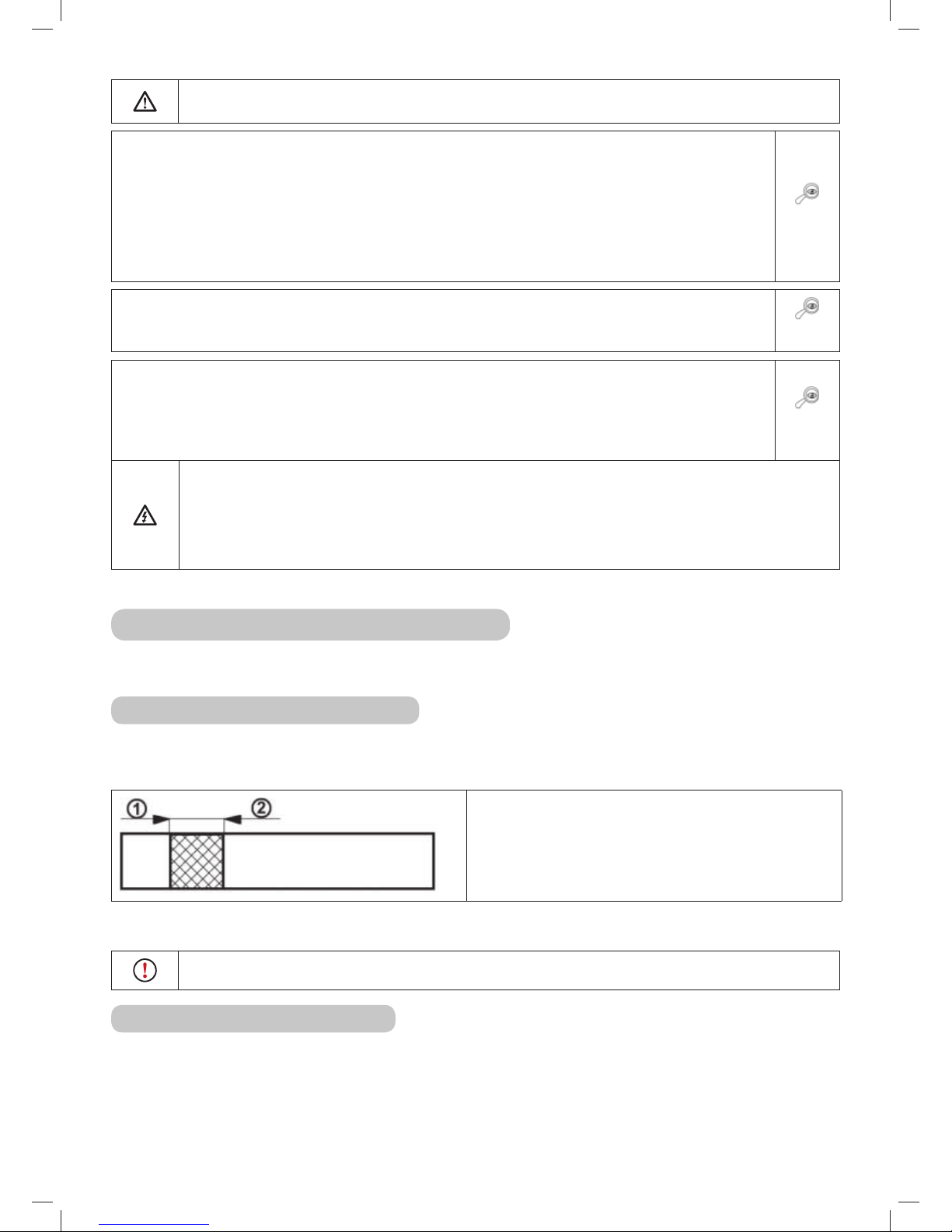
front wheel half-axles – on AC 92-23 4x4 mower, the interval is 10 hours!
Pivot points are lubricated with oil:
differential lock pedal
brake pedal
travel levers
rear wheel half axles - the interval is 10 hours
Page 41

41
7. REPAIRING MALFUNCTIONS AND DEFECTS
Do not perform any repairs if you do not have the appropriate technical equipment and qualifications.
The repairs described below may be performed by the user of the machine. Other repairs performed by
the user that are not specified here will void the warranty. The manufacturer takes no responsibility for
damages resulting from poorly performed unapproved repairs by the user.
Malfunction, defect Remedy
The mowing deck
mows unevenly
Remove grass that has accumulated on the underside of the mowing deck.
Make sure that the blades are sharp, are not deformed or damaged.
Check that the blades are properly fastened.
Check the blade shafts and the seating of the bearings. Replace them if they are damaged or
overly worn.
When mowing,
some vegetation
remains uncut
Check the bearing housings for damage. Based on your findings either repair or replace them.
When mowing thick grass or grass that is too wet, an unmowed strip may remain. The travel
speed should be adjusted to respect the mowing conditions by shifting into a suitable gear. The
engine should not run with the throttle valve fully open.
Check that the blades are sharp and undamaged. Replace the blades if necessary.
Check the tension and condition of the V-belt of the mowing drive
The mowing deck
drive belt stops
during operation
The mowing deck drive belt may be damaged, when it jumps out of the pulley while the machine
is running. If it jumps out even after rechecking according to the following steps, it is necessary to
replace the belt.
Check the tension of the belt (
6.3.7). If necessary adjust the tension.
Check the belt guide pulleys.
Check the set mowing height, adjust if necessary.
Check whether the movement of the belt is not prevented by a foreign object. If yes, remove the
foreign object.
Recheck all the belts. Buckled or cracked pulleys may cause problems. Replace if necessary.
Check the inside surface of the pulley on the engine. If it is coarse or has cracks, it is necessary to
replace the pulley.
Check the parts of the tensioning mechanism for wear, replace the worn out parts if necessary.
Change the travelling speed (e.g. slow down)
Lift the mowing deck to a higher position
The mowing
deck drive belt is
slipping through
If the grass is too tall or wet, the mowing deck drive belt may slip through. Check that the belt is
not worn out. If it is, replace it.
Reduce the speed of the machine.
Increase the mowing height.
Check belt tension. If necessary adjust the tension.
Check the tensioning mechanism (spring, pulley). Replace the spring if it is overstretched or
damaged.
The mowing deck
drive belt is being
excessively worn
out
Check the belt guide pulley.
Check whether the movement of the belt is not prevented by a foreign object. If yes, remove the
foreign object.
Check the pulleys, if they are damaged, replace them.
Check the set mowing height, adjust if necessary.
Check the tension of the belt (
6.3.7). If necessary adjust the tension.
The mowing deck
cannot be started
Check that the belt is not worn out or damaged. If it is, replace it. If it is loose, tension it.
Check the tensioning mechanism spring. Replace the spring if it is cracked or damaged.
Check whether the movement of the belt is not prevented by a foreign object. If yes, remove the
foreign object.
Check the position of the mowing height lever. The safety switch prevents the activation of the
electromagnetic clutch when in the transport position. Move the lever to the work position.
Check the setting of the mowing deck switch
Page 42

42
Malfunction, defect Remedy
Belts vibrate
extremely when
turning on the
mowing deck
Check that the blades are not bent or twisted, also check that they are balanced. If they are
deformed, replace them.
Check that the belt does not have burned areas or irregularities, which could cause the vibrations.
If the belt is damaged, replace it.
Check that the blades are not worn out or damaged. Replace them if necessary.
Check that the electromagnetic clutch switches properly. If the clutch is not working properly
have it replaced or repaired at an authorised service centre.
Check the inside surface of the pulley on the engine. If it is coarse or has cracks, it is necessary to
replace the pulley.
Check whether grass has accumulated on the underside of the mowing deck. It is necessary to
remove this grass.
Check whether the defect is not in the engine mount. Tighten bolts or replace as necessary.
Check the tension of the belt (
6.3.7. If necessary adjust the tension.
The travel drive
belt of the machine
is slipping
Check the tension of the travel drive belt (
6.3.8). If necessary adjust its tension. Also check
the tension spring, replace it if necessary.
Check whether the belt is damaged or worn out.
Check whether the movement of the clutch mechanism is blocked by a foreign object. If yes,
remove the foreign object.
Check the engine pulley or transmission pulley for damage. Replace if necessary.
The travel drive
belt is being
excessively worn
out
Check belt tension.
Check the tensioning mechanism, replace the damaged spring
Check whether a foreign object is blocking the movement of the belt. If yes, remove the foreign
object.
Check the condition of the pulleys - replace the pulleys if necessary.
The machine does
not travel after
shifting into gear
Check the gear shifting mechanism - attachment of the draw bar of the travel direction lever.
Check the oil level in the equalisation tank
The machine is
unusually loud
after shifting into
gear
Check the oil level in the equalisation tank and fill it up if necessary.
There are air pockets in the hydraulic circuit – drive the machine on level ground forward and
back for several minutes. Contact your service centre.
The machine
loses power when
travelling up a hill
When the machine is under a high load and the ambient temperature is high, then the maximum
working temperature of the oil may be exceeded. Lower the work demands on the machine.
Extreme vibrations
occur when
travelling
Check whether any pulleys are damage or deformed. Replace them if necessary.
Check whether the belt has any burned spaces or other irregularities. Replace it if necessary.
Check the tension of the travel drive belt (
6.3.8). If necessary adjust its tension.
Check that the mowing blades are balanced. Balance or replace them if necessary.
The steering is
slipping through or
loose
Check that the space between the pinion and the segment is not too large. If yes, adjust the
cogged segment. Check for wear on the ball and socket joints. Replace the joints if necessary.
The engine does
not run
Check that there is petrol in the petrol tank.
Check that the prescribed procedure for starting the engine was followed (
5.2)
Check the fuse. Replace if necessary.
Check whether the voltage on the battery terminals is 12 V. On a new machine check whether the
battery was activated and charged. On new machines replace the spark plug and check that there
is not oil accumulated on the cylinder due to incorrect handling.
Check that all wire connections are in order and that the electrical system switches work.
Check the engine again exactly according to the instructions in the User’s manual of the engine
manufacturer. Have the electrical system checked at a specialised workshop.
Page 43

43
Malfunction, defect Remedy
The engine is
rotating but will
not start up
Check that the prescribed procedure for starting the engine was followed (
5.2). Check that
the petrol in the petrol tank is clean.
Check that the fuel filter is not clogged.
Make sure that the throttle lever is in the position “CHOKE”.
Check the engine again exactly according to the instructions in the User’s manual of the engine
manufacturer. Have the cabling and switches checked at a specialised workshop.
7.1 ORDERING SPARE PARTS
We recommend that you use exclusively original spare parts, which ensure safety and compatibility.
Always order spare parts from an authorised distributor or service organisation, which is informed
about the current technical changes performed on the products during manufacture.
For easy, fast and exact identification of the necessary spare part always provide in your order the serial
number found on the second side of the cover of this publication. Also provide the year of manufacture
as shown on the product identification label under the seat.
7.2 WAR R A N T Y
Warranty conditions are provided on the warranty card, which is always provided together with the
product by the seller.
Page 44

44
8. POST-SEASONAL MAINTENANCE, PUTTING THE
MACHINE OUT OF OPERATION
After the end of the season or if you will not be using your riding mower for more than 30 days, make
sure to prepare your machine for storage as soon as possible. If fuel remains in the petrol tank without
movement for more than 30 days, a sticky deposit may form, which can have a negative effect on the
carburettor and cause poor engine operation. For this reason empty the petrol tank.
Never store the riding mower with a full petrol tank inside of buildings or poorly
ventilated areas, where there are fuel vapours, open flames, sparking or lighting
flames, furnaces, central heating, dry rags, etc. Handle fuels and lubricants with
care, they are highly flammable and careless handling may lead to serious burns
or damage to property.
Only empty the petrol tank into approved containers outdoors away from open
flames.
Recommended procedure for preparing the riding mower for storage:
Thoroughly clean the entire machine, especially inside the mowing deck (
6.2.2).
Never use petrol for cleaning. Use degreasing agents and warm water.
Repair and paint dinted places to prevent corrosion from occurring.
Replace faulty or worn out parts and tighten all loose nuts and bolts.
Prepare the engine for storage according to the user’s manual for the operation and maintenance of
the engine.
Lubricate all lubrication locations according to the lubrication diagram (
6.4).
Take out the battery, clean it, fill it up with distilled water all the way to the bottom parts of the rings
of the filling openings and charge fully. A battery that is not charged may freeze and crack. Store the
battery in a cool, dry location, as necessary. Charge the battery every 30 days and regularly check its
voltage.
Store the riding mower covered in a clean and dry environment.
The best way to ensure the riding mower‘s ideal operating condition for the next season is
to have it inspected and tuned at an authorised service centre every year.
8.1 MACHINE BELTS
It is not necessary to loosen the belts when the machine is taken out of operation for an extended
period of time. When the machine is started up for use again, we strongly recommend that you allow
the machine belts to run free for at least 5 minutes. This will prevent vibrations and ensure that
after an extended period of inactivity the belts will align into the correct working position.
Page 45

45
9. DISPOSAL OF THE MACHINE
After the operational life of the machine is over, the owner of the machine is responsible for its disposal.
This may be performed in two ways:
a) Hand the machine over to a specialised company (scrap yard, secondary waste collection point, etc.).
You will receive documented confirmation of the handover for disposal.
b) Dispose of the machine yourself. In this case we recommend the following procedure:
Dispose of the product utilising recyclable material according to the applicable waste disposal law.
Disassemble the entire machine.
Parts that can be reused should be cleaned, preserved and stored for further use.
Separate the remaining parts into those that are and are not environmentally friendly, e.g. rubber
parts (gaskets), lubricant remains in the bearings or on gears. The environmentally harmful
components must be handled according to the relevant waste disposal law applicable in the country
of the user, e.g. in the Czech Republic it is the Waste Act No. 185/2001 Coll.
Sort the waste according to the Wastes Catalogue in accordance with the relevant ordinance.
Handle environmentally friendly parts as a reusable resource.
Page 46

46
10. ES STATEMENT OF COMPLIANCE
pursuant to: Council Directive No. 2006/42/EC (Government directive NV 176/2008 Coll.)
Council Directive No. 2004/108/EC (Government directive NV 616/2006 Coll.)
Council Directive No. 2000/14/EC (Government directive NV 9/2002 Coll.)
A. We: Seco Group a.s., Šaldova 408/30, Prague 8
branch: 02 Jičín, Jungmannova 11
Corporate number: 60193450
issue the following statement:
B. Mechanical equipment
- name: Riding mower
- model: AC 92
- serial number:
Description:
AC 92 is a four-wheel self-propelled riding mower with a Briggs & Stratton 18HP, 20HP, 23HP engine. The
power drive from the engine is transferred by a V-Belt to the travel drive transmission with a continuously
variable gear and through an electromagnetic clutch to the mowing deck. The mowing deck is a singlerotor assembly with a vertical axis of rotation and a coverage width of 92 cm. It has two rotating blades on
a single carrier. The mowed material is dispersed on the ground.
C. Legislation forming the basis for assessment of compliance:
EN ISO 836+A4, EN ISO 3767-1;3, ISO 11684, EN ISO 11201, EN ISO 12100-2
Council Directive No. 97/68/EC (2002/88/EC)
D. Assessment of compliance was performed according to the designated procedure in:
- Council Directive No. 2006/42/EC, Article 5, (eqv. §5, para. 2 a), NV No. 176/2008 Coll.)
- Council Directive No. 2004/108/EC, Article 7, (eqv. §4, para. 1, NV No. 616/2006 Coll.)
- Council Directive No. 2000/14/EC, Annex VIII,(eqv.annex 7, NV No.9/2002 Coll.)
under the supervision of a notified person from LRQA registration number 0088
71 Fenchurch street
London EC3M 4BS, United Kingdom
E. Entities participating in the assessment of compliance:
Authorised entity no. 255, Notified entity no. 1016
Státní zkušebna zemědělských, lesnických a potravinářských strojů a.s. (SZZPLS)
Třanovského 622/11, 163 04 Prague 8, Czech Republic
Final Report No. 33 257 and 31 768
F. We confirm that:
- this mechanical equipment defined above complies with the requirements in the above technical
regulations and under normal operating conditions it is s a f e.
- measures have been taken to ensure the compliance of all products introduced to the market with the
technical documentation and the requirements contained in technical regulations.
- guaranteed emission level of acoustic power L
WA G
is 100 dB(A)
Measured mean values of acoustic power depending on the engine used:
Engine Speed (min-1) Measured level of acoustic power LWA [dB(A)]
BRIGGS & STRATTON 18 HP VANGUARD 3000±100 97
BRIGGS & STRATTON 20 HP VANGUARD 3000±100 97
BRIGGS & STRATTON 23 HP VANGUARD 3000±100 98
Technical documentation of the scope required by appendix VII to regulation 2006/42/EC and by appendix VIII of
regulation 2000/14/EC is kept by the manufacturer at the following address:
Seco GROUP
odštěpný závod 02 AGS
Jungmannova 11
506 48 Jičín
In Jičín, on 1. 10. 2012 Ing. Jiří Pávek
Member of the Board of Directors
Page 47

47
Seco GROUP a.s. is dedicated to the continuous development and improvement of all its machines. Therefore,
some technical differences in terminology may appear in this manual when compared with the actual product.
No claims can be deduced from this. Print, duplication, publication and translation (even in part) must not be
performed without the written consent of Seco GROUP a.s. The manufacturer reserves the right to change technical
parameters of the product, without prior customer notifi cation.
Page 48

48
VORWORT
Sehr geehrter Kunde,
Vielen Dank für den Kauf dieses Aufsitzmähers von Seco GROUP a.s., ein sowohl in Europa als auch
international renommiertes Unternehmen als Hersteller von hochwertigen Maschinen und Zubehör für
die Pflege von Rasenflächen.
Dieses Handbuch enthält Anweisungen über die sichere Montage, den Betrieb und die Wartung Ihrer Maschine.
Lesen Sie diese Bedienungsanleitung sorgfältig durch. Befolgen Sie die in diesem Handbuch
enthaltenen Anweisungen genau, so dass die Bedienung der Maschine einfacher ist und
sie optimal genutzt wird und eine lange Lebensdauer hat. Verwenden Sie die Maschine
erst, wenn Sie alle Anweisungen, Einschränkungen und Empfehlungen in diesem
Handbuch gründlich gelesen haben.
Bewahren Sie die Bedienungsanleitung für den späteren Gebrauch auf. Dieses Handbuch muss als
Teil des Aufsitzmähers angesehen werden, das beim Verkauf des Mähers beigefügt werden muss.
Wenn etwas unklar ist oder Sie Fragen haben, zögern Sie nicht, sich an eine unserer mehr als 100
autorisierten, professionell ausgestatteten Kundendienststellen in ganz Europa zu wenden, wo geschulte
und geprüfte Experten bereit stehen, um Ihnen zu helfen.
IN DIESEM HANDBUCH VERWENDETE SYMBOLE
SYMBOL BEDEUTUNG
Diese Symbole bedeuten „ACHTUNG“ und „WARNUNG“. Sie informieren Sie über Dinge,
die Ihre Maschine beschädigen und/oder zu schweren Verletzungen für den Benutzer
führen können.
Dieses Symbol weist auf eine wichtige Anweisung, Eigenschaft, ein Verfahren oder Thema
hin, dessen Sie sich bewusst sein müssen, und woran Sie sich bei Montage, Betrieb und
Wartung der Maschine halten müssen.
Dieses Symbol weist auf nützliche Informationen zur Maschine oder deren Zubehör hin.
Das Symbol ist ein Verweis auf ein Bild im vorderen Teil der Bedienungsanleitung. Es wird
immer durch die Nummer des Bildes begleitet.
Dieses Symbol ist ein Verweis auf ein weiteres Kapitel in diesem oder einem anderen
Benutzerhandbuch und wird meist zusammen mit der Nummer des Kapitels angezeigt,
auf das es sich bezieht.
HINWEISE AUF RICHTUNGEN
Linke und rechte Seite Vorder- und Rückseite
L
R
R
V
L = linke Seite, R = rechte Seite R = Rückseite, V = Vorderseite
Page 49

49
1. TECHNISCHE INFORMATIONEN
1.1 VERWENDUNG
Das Maschinenmodell AC92-18 (20) oder AC92-23 4x4 mit dem Markennamen CrossJet ist ein
zweiachsiger Gelände-Aufsitzmäher zum Mähen gepflegter und ungepflegter grasbewachsener
und geneigter Flächen bis zu einer Neigung von 18° (32 %), die frei von Fremdkörpern sind (Steine,
abgebrochene Äste, Knochen, harte Gegenstände, usw.). Die Maschine kann eingesetzt werden, um
mit Himbeeren, Brombeeren und verschiedenen anderen Ranken verflochtene mehrjährige Pflanzen zu
mähen.
Jegliche Nutzung dieses Aufsitzmähers, die nicht in diesem Handbuch beschrieben
ist und die über die hier beschriebene Verwendung hinausgeht, wird als nicht
vorgesehener Zweck oder Gebrauch betrachtet. Der Hersteller der Maschine ist nicht
verantwortlich für Schäden, die aus einer solchen Nutzung entstehen; der Nutzer trägt das
volle Risiko. Der Nutzer ist auch für die Einhaltung der Bedingungen verantwortlich, die der
Hersteller für Betrieb, Wartung und Reparatur der Maschine vorschreibt. Diese darf nur
von Personen verwendet, gewartet und repariert werden, die diese Bedingungen
kennen und die über mögliche Gefahren informiert sind.
Nur vom Hersteller genehmigtes Zubehör darf an der Maschine angebracht werden.
Durch die Verwendung von anderem Zubehör erlischt die Garantie sofort.
1.2 HAUPTELEMENTE DES AUFSITZ-MÄHERS
Die Aufsitzmäher AC 92-18, AC 92-20 oder AC 92-23 4x4 bestehen aus den folgenden Basissektionen:
1.2
(1) Haube mit Stauraum
Die Haube ist eine Kombination aus Kunststoff- und Metallabdeckungen, die den Stauraum
für die Batterie enthalten.
(2) Chassis mit Stoßstange
Das Chassis mit der Stoßstange dient als tragendes Element für die meisten Hauptteile der
Maschine.
(3) Vorderachse mit Rädern einschließlich Lenkung*
Die Lenkung erfolgt über die Räder der Vorderachse. Die Räder werden vom Lenkrad mittels
eines Kammmechanismus gedreht.
Der AC 92-23 4x4 ist mit einem Frontantrieb ausgestattet. Der Allradantrieb wird
automatisch aktiviert. Dabei verteilt sich die Kraft auf die einzelnen Achsen, je nach
aktuellen Traktionsbedingungen und Fahrmodus (vorwärts oder rückwärts).
(4) Mähwerk
Das Mähwerk mäht das Gras. Es befindet sich unter der Maschine. Es besteht aus Abdeckung,
Hauptplatte, Messerhaltern und zwei massiven Mähmessern. Das Mähwerk wird vom Motor
der Maschine über eine elektromagnetische Kupplung und einen Keilriemen angetrieben.
(5) Motor, Getriebe, einschließlich Heckantrieb über einen Bypass
Der Viertakt-Benzinmotor ist im hinteren Teil der Maschine am Chassis montiert. Das
Getriebe mit hydrostatischer Kraftübertragung dient zum Schalten der Gänge während
der Fahrt. Der Bypass-Hebel befindet sich an der Rückwand der Maschine. Er dient zur
Aktivierung und Deaktivierung des Getriebes für die Hinterräder.
(6) Faltrahmen der Maschine
Der Faltrahmen soll verhindern, dass die Maschine um 180° umkippt, wenn sie aus
irgendeinem Grund die Stabilität verliert und zur Seite kippt.
(7) Fahrerposition
Der bequeme Sitz ermöglicht einen einfachen Zugriff auf alle Bedienelemente der Maschine.
Der verwendete Sitz sorgt für eine sichere und komfortable Bedienung.
Page 50

50
*ACHTUNG: Beim AC92-23 4x4 kann aus Konstruktionsgründen der Frontantrieb
nicht abgeschaltet werden - das Hydrauliksystem ist nicht mit einem Bypass-Ventil
ausgestattet, was die Möglichkeit, die Maschine zu bewegen, wenn der Motor nicht läuft,
deutlich einschränkt. Während dieser Bewegung wird die Vorderachse deutlich überlastet
und kann beschädigt werden. Der Bypass-Hebel dieser Maschine wird in erster Linie dazu
verwendet, das hydrostatische System zu entlüften. Die Maschine darf nicht verwendet
werden (ein Gang eingelegt werden), wenn sich der Bypass-Hebel in der deaktivierten
Stellung befindet - es besteht die Gefahr von Schäden am Getriebe!!
1.3 KENNZEICHNUNGSETIKETT DES PRODUKTS UND ANDERE
ETIKETTEN MIT SYMBOLEN, DIE AN DER MASCHINE VERWENDET
WERDEN
1.3.1 KENNZEICHNUNGSETIKETT DES PRODUKTS
Jeder Aufsitzmäher ist mit einem Produkt-Kennzeichnungsetikett markiert, das sich unter der Sitzbank
befindet. Es ist durch Anheben des Sitzes zugänglich.
1.3.1
1. Maschinenmodell
2. Motormodell
3. Baujahr
4. Gewicht
5. Name und Adresse des Herstellers
6. Verwendete EG-Codes zur Compliance-Bewertung des Produkts
7. Compliance-Zeichen des Produkts
8. Hersteller-Logo
9. Garantierter Schallpegel gemäß Richtlinie 2000/14/EG
Der Verkäufer notiert bei der Übergabe der Maschine die Seriennummer auf der Rückseite
des Deckblatts dieser Anleitung.
1.3.2 ANDERE ETIKETTEN UND IHRE BEDEUTUNG
Die folgenden Etiketten und Aufkleber sind an der Maschine angebracht:
Etiketten am Mähwerk:
1.3.2a
Gefahr
Nicht auf die
Maschine steigen
Rotierende
Werkzeuge
100
dB
Garantierter
Schallleistungspegel
Page 51

51
Etiketten an der Verkleidung unter dem Sitz:
1.3.2b
Gefahr
Nicht während
des Betriebs
berühren
Bei der
Reparatur
Anleitung
befolgen
Maschine
nicht während
des Fahrens
verlassen
Achtung,
umherfliegende
Objekte
Lesen Sie das
Handbuch
Nicht in der
Nähe anderer
Menschen
mähen
Keine
Passagiere
mitnehmen
Nicht senkrecht
zum Hang
fahren
Unbefugte
Personen
in sicherem
Abstand halten
MAX
18
o
Maximale
Arbeitssteigung
Etiketten auf der Rückseite der Maschine:
1.3.2c
Vorsicht
Heiße
Oberfläche!
Gefahr von
Verbrennungen
Etiketten auf dem Fahrtrichtungshebel:
1.3.2d
Choke
Temp o r egl e r
0
Temporegler aktiviert
1
Temporegler deaktiviert
Schnell
Langsam
F
Vorwär ts
N
Neutral
R
Rückwärts
Es ist strengstens verboten, am Zubehör angebrachte Etiketten und Symbole zu entfernen
oder beschädigen. Bei Beschädigung oder Unlesbarkeit des Etiketts kontaktieren Sie bitte
den Lieferanten oder Maschinenhersteller und fordern Ersatz an.
Page 52

52
1.4 TECHNISCHE PARAMETER
BASISPARAMETER EINHEITEN AC 92-18 (20) AC 92-23 4x4
Abmessungen der Maschine
(Länge x Breite x Höhe)
[mm] 2310 x 1010 x 1510 2310 x 1050 x 1510
Radstand
Vorne
[mm]
814 814
Hinten 780 790
Gewicht der Maschine [kg] 317 350
Geschwindigkeit vorwärts /
rückwärts
[km/h] 0-8,5 / 0-4,5 0-9 / 0-5
Schnitthöhe [mm] 50-100
Schnittbreite [mm] 920
Radabmessungen
Vorne
["]
16x6,5-8 16x6,5-8
Hinten 20x10,0-8 20x10,0-8
Fassungsvermögen des
Kraftstofftanks
[l] 12
Kraftstofftyp --- Bleifreies Benzin 95
Garantierter Schallleistungspegel
L
WA
[dB] <100
Angegebener EmissionsSchalldruckpegel am Betriebsort
L
pAd
gemäß EN ISO 11201
[dB] <100
Batterietyp --- 12V 24aH 12V 32aH
* - Genaue Werte finden Sie in der Tabelle auf der nächsten Seite.
Page 53

53
Motor
Drehzahl
±100
(min-1)
Angegebener
Emissionsschalldruckpegel
am Ort des Betriebs
L
pAd
(dB) nach EN ISO
836+A1/A2, Anlage H und
EN ISO 11201
Schwingbeschleunigung Gesamtwert (m.s
-2
)
gemäß EN 836+A1/A2, Anlage G
Sitz Lenkrad Boden
BS18 3000 88,4 0,23 2,38 1,61
Gesamtschwingungen a
v
gemäß EN 1032
Auf den Arm
übertragene
Schwingungen a
hv
gemäß EN 1033
BS20 3000 90 0,56 < 2,5
BS23 3000 91 1,5 < 2,5
Page 54

54
2. ARBEITSSICHERHEIT UND GESUNDHEIT
Die Aufsitzmäher-Modelle Ac 92-18, AC 92-20 und AC 92-23 4x4 unter dem Markennamen CrossJet
sind nach den gültigen europäischen Sicherheitsnormen gefertigt. Der Hersteller der Maschine bestätigt
diese Tatsache in der Compliance-Erklärung am Ende dieser Bedienungsanleitung ( 10).
Wenn diese Maschine richtig und gemäß der Bedienungsanleitung verwendet wird, ist sie sehr sicher.
Wenn die Arbeitssicherheit nicht eingehalten und nicht alle Warnungen in
diesem Handbuch beachtet werden, kann dieser Aufsitzmäher Hände oder Beine
abtrennen oder Gegenstände ablenken und dadurch schwere Verletzungen oder
den Tod von Personen, Beschädigung oder Zerstörung der Maschine oder eines
ihrer Teile oder des Zubehörs verursachen.
2.1 SICHERHEITSANWEISUNGEN
Die Person, die in erster Linie für ihre eigene Sicherheit und die Sicherheit anderer beim Betrieb des
Aufsitzmähers verantwortlich ist, ist dessen Benutzer. Der Hersteller übernimmt keine Verantwortung
für die Verletzung von Personen oder für Schäden an der Maschine und Umweltschäden, die daraus
resultieren, dass die Maschine nicht gemäß allen Sicherheitsanweisungen in diesem Handbuch betrieben
wird.
2.1.1 ALLGEMEINE SICHERHEITSHINWEISE
! Diese Maschine darf nur von einer Person über 18 Jahren, die dieses Handbuch gelesen hat, gefahren
werden.
! Der Benutzer der Maschine ist für die Sicherheit von Personen in der Nähe des Arbeitsbereiches der
Maschine verantwortlich.
! Es ist nicht gestattet, ohne schriftliche Zustimmung des Herstellers technische Modifikationen an
der Maschine und deren Zubehör vorzunehmen. Unerlaubte Modifikationen können zu gefährlichen
Arbeitsbedingungen führen und die Garantie erlöschen lassen.
! Beachten Sie alle Auflagen zur Brandsicherheit (
2.4).
! Entfernen Sie keine Sicherheitsaufkleber oder Etiketten von der Maschine.
! Bleiben Sie nicht in der Nähe der Maschine oder unter ihr, wenn sie angehoben ist und nicht ausreichend
gegen Herabfallen oder Umkippen in der angehobenen Position gesichert ist.
! Schalten Sie immer das Mähwerk und den Motor aus und ziehen Sie den Schlüssel aus dem
Zündschloss, wenn:
Sie die Maschine reinigen
Sie angesammeltes Gras aus dem Mähwerk entfernen
Sie über einen Fremdkörper gefahren sind und es notwendig ist zu überprüfen, ob die Maschine beschädigt
wurde, oder ob es notwendig ist, den Schaden zu beheben
die Maschine ungewöhnlich stark vibriert und es notwendig ist, die Ursache der Vibrationen herauszufinden
Sie den Motor oder andere bewegliche Teile reparieren (ziehen Sie auch die Kabel von den Zündkerzen ab)
2.1.2 BEVOR DIE MASCHINE BENUTZT WIRD
! Verwenden Sie den Aufsitzmäher nicht, wenn er beschädigt ist oder eine seiner Schutzvorrichtungen
fehlt. Alle Abdeckungen und andere Schutzelemente müssen immer angebracht sein. Entfernen oder
setzen Sie keine Schutzelemente der Maschine außer Betrieb. Die richtige Funktion dieser Elemente
ist regelmäßig zu kontrollieren.
! Nach dem Konsum von Alkohol, Drogen oder Medikamenten, die Ihre Wahrnehmung beeinträchtigen,
dürfen Sie nicht mit der Maschine arbeiten.
! Nicht mit der Maschine arbeiten, wenn Sie an Schwindel- oder Ohnmachtsanfällen leiden oder wenn
Sie auf sonstige Weise geschwächt oder abgelenkt sind.
! Bevor Sie die Maschine in Betrieb nehmen, informieren Sie sich gründlich über alle Bedienelemente
und sorgen dafür, dass sie diese so bedienen können, dass Sie, wenn nötig, den Motor sofort anhalten
oder ausschalten können.
Page 55

55
! Verstellen Sie nicht den Motorregler oder den Drehzahlbegrenzer des Motors.
! Bevor Sie mit der Maschine zu arbeiten beginnen, entfernen Sie alle Steine, Holzstücke, Drähte,
Knochen, heruntergefallenen Äste und anderen Gegenstände, die während des Mähvorgangs
abgelenkt werden könnten, von der zu mähenden Fläche.
! Beheben Sie vor der weiteren Verwendung alle Mängel. Überprüfen Sie vor Arbeitsbeginn, dass die
Riemen gespannt sind, die Messer scharf sind und dass der Bereich innerhalb des Mähwerks frei ist.
2.1.3 WÄHREND DER BENUTZUNG DER MASCHINE
! Da diese Maschine zum Mähen von Gras auf ungepflegten Flächen gedacht ist, bei denen der Bediener
die zu mähende Fläche nicht immer voll einsehen kann und ihren Zustand nicht immer kennt (Gräben
oder Löcher), ist die Maschine mit einem Faltrahmen ausgestattet.
! Die Maschine darf nicht für die Arbeit an Hängen mit einer Neigung von mehr als 18° (32 %), und
bei Verwendung des 4x4-Antriebs an Hängen mit einer Neigung von mehr als 20° (32%), verwendet
werden.
! Der Transport von Personen, Tieren oder Lasten direkt auf der Maschine ist verboten. Der Transport
von Lasten ist nur auf Anhängern erlaubt, die vom Maschinenhersteller zugelassen sind.
! Auch beim Verlassen der Maschine für kurze Zeit immer den Schlüssel aus dem Zündschloss ziehen.
! Wenn Sie die Maschine aus dem Arbeitsbereich fahren, wo Sie mähen, deaktivieren Sie immer das
Mähwerk und heben es in die Transportstellung.
! Nicht in der Nähe von Materialstapeln, Löchern oder Böschungen mähen. Der Aufsitzmäher kann sich
plötzlich überschlagen, wenn ein Rad über den Rand eines Loches oder eines Grabens oder über eine
Kante fährt, die zusammenbricht.
! Bei der Arbeit Betonstützen, Baumstümpfe, Gartenbeet- und Fußwegrandsteine vermeiden, die
nicht mit den Messern in Kontakt kommen dürfen, da sie sonst Schäden am Mähwerk und dem
Maschinenmechanismus verursachen können.
! Beim Aufprall auf einen festen Gegenstand Mähwerk und Motor anhalten und ausschalten und
die gesamte Maschine, vor allem die Lenkung, überprüfen. Notwendige Reparaturen vor der
Wiederinbetriebnahme des Motor durchführen.
! Wenn möglich, die Maschine nicht auf nassem Gras einsetzen. Reduzierte Traktion kann zu
Rutschgefahr führen.
! Vermeiden Sie Hindernisse (z. B. plötzliche Änderungen der Neigung eines Hangs, Gräben, usw.), wo
die Maschine umkippen könnte.
! Wenn das Mähen deaktiviert ist, muss sich das Mähwerk immer in der Transportstellung befinden.
! Versuchen Sie nicht, die Stabilität der Maschine zu erhalten, indem Sie auf den Boden treten.
! Die Maschine nur bei Tageslicht oder bei guter künstlicher Beleuchtung benutzen.
! Das Fahren der Maschine auf öffentlichen Straßen ist nicht erlaubt.
! Beim Betrieb der Maschine keine weite Kleidung und kurze Hosen tragen. Feste vollständig
geschlossene Schuhe tragen. Nie die Maschine mit Sandalen oder barfuß bedienen.
! Den Motor nicht in geschlossenen Bereichen laufen lassen. Die Abgase enthalten Stoffe, die geruchlos
aber tödlich giftig sind.
! Halten Sie Ihre Hände oder Beine nicht unter die Abdeckung des Mähwerks. Halten Sie nie ein
Körperteil in die Nähe der rotierenden oder beweglichen Teile der Maschine.
! Den Motor nicht ohne Auspuff starten.
! Normalerweise übersteigen die beim Mähen abgegebenen Geräusche nicht die in dieser
Bedienungsanleitung angegebenen Schalldruck- und Schallleistungswerte (
1.4). In bestimmten
Fällen können jedoch unter bestimmten Bedingungen und aufgrund der Beschaffenheit des Geländes
die angegebenen Geräuschpegel kurzzeitig überschritten werden.
! Der Hersteller der Maschine empfiehlt bei der Bedienung der Maschine die Verwendung von
Gehörschutz, da die Belastung des Hörorgans durch einen übermäßigen Geräuschpegel oder durch
Langzeiteffekte zu dauerhaften Hörschäden führen kann.
Page 56

56
! Konzentrieren Sie sich immer voll auf das Fahren und andere mit der Maschine durchgeführte
Aktivitäten. Die häufigsten Ursachen für den Verlust der Kontrolle über die Maschine sind zum Beispiel:
Der Verlust der Radtraktion.
Überhöhte Geschwindigkeit, Nichtanpassen der Geschwindigkeit an aktuelle Gegebenheiten und
Geländeeigenschaften.
Plötzliches Bremsen, bei dem die Räder blockieren.
Einsatz der Maschine für Zwecke, für die sie nicht konstruiert wurde.
2.1.4 NACH DER ARBEIT MIT DER MASCHINE
! Halten Sie die Maschine und das Zubehör immer sauber und in gutem technischen Zustand.
! Die rotierenden Messer sind scharf und können Verletzungen verursachen. Beim Umgang mit den
Messern immer Schutzhandschuhe tragen oder die Messer umwickeln.
! Überprüfen Sie regelmäßig die Muttern und Schrauben, die die Messer sichern, darauf, dass sie mit
dem entsprechenden Drehmoment angezogen sind (
6.3.6).
! Achten Sie besonders auf Sicherungsmuttern. Wenn die Mutter zum zweiten Mal gelöst wurde, ist ihre
Sicherungsfähigkeit reduziert und sie muss durch eine neue ersetzt werden.
! Kontrollieren Sie regelmäßig alle Komponenten und wenn nötig ersetzen Sie diejenigen, die gemäß
den Empfehlungen des Herstellers ersetzt werden müssen.
2.2 SICHERHEITSVORSCHRIFTEN FÜR DIE ARBEIT AN HÄNGEN
Hänge sind die Hauptursache für Unfälle, Kontrollverlust über die Maschine oder nachfolgendes
Umkippen, was jeweils zu schweren Verletzungen oder zum Tod führen kann. Das Mähen an Hängen
erfordert immer ein erhöhtes Maß an Aufmerksamkeit. Wenn Sie nicht sicher sind oder es Ihre
Fähigkeiten übersteigt, mähen Sie nicht an Hängen.
! Aufsitzmäher können an Hängen mit einer maximalen Steigung von bis zu 18° (32%) und beim
Einsatz des 4x4-Antriebs an Hängen mit einer maximalen Neigung von 20° (32%) und nur in Richtung
der Falllinie, also nach oben oder unten, eingesetzt werden. Weitere Informationen
5.5.4.
! Bei der Richtungsänderung ist erhöhte Vorsicht geboten. Nicht an einem Hang drehen, wenn es nicht
absolut notwendig ist.
! Achten Sie auf Löcher, Wurzeln, unebenes Gelände. Unebenes Gelände kann dazu führen, dass die
Maschine umkippt. Hohes Gras kann verborgene Hindernisse enthalten. Entfernen Sie daher im Voraus
alle Fremdkörper von der zu mähenden Fläche.
! Wählen Sie eine solche Geschwindigkeit, dass Sie auf einem Hügel nicht stoppen müssen.
! Seien Sie sehr vorsichtig, wenn Sie verschiedene Anhänger anbringen. Dies kann zu einer verringerten
Stabilität der Maschine führen.
! Führen Sie alle Bewegungen am Hang langsam und gleichmäßig aus. Nehmen Sie keine plötzlichen
Geschwindigkeits- oder Richtungsänderungen vor.
! Vermeiden Sie Anfahren oder Anhalten am Hang. Wenn die Räder ihre Traktion verlieren, schalten Sie
den Messerantrieb ab und fahren Sie langsam den Hügel hinab.
! Fahren Sie an einem Hang sehr vorsichtig und langsam an, sodass die Maschine nicht „springt“.
Reduzieren Sie vor einem Hang immer die Fahrgeschwindigkeit der Maschine. Verringern Sie
insbesondere die Fahrgeschwindigkeit auf ein Minimum, wenn Sie einen Hügel hinunterfahren, um die
Motorbremse zu nutzen. Diese Bremswirkung ist beim AC 92-23 4x4 deutlich höher.
2.3 SICHERHEIT VON KINDERN
Wenn der Bediener des Aufsitzmähers nicht auf die Anwesenheit von Kindern vorbereitet ist, können
tragische Unfälle passieren. Die Bewegung eines Aufsitzmähers zieht die Aufmerksamkeit von Kindern
auf sich. Gehen Sie niemals davon aus, dass Kinder an dem Ort bleiben, an dem Sie sie das letzte Mal
gesehen haben.
! Lassen Sie Kinder nicht ohne Aufsicht in Bereiche, in denen Sie Gras mähen.
! Seien Sie immer bereit - wenn sich Ihnen Kinder nähern, schalten Sie das Gerät aus.
! Beim Vorwärts- und Rückwärtsfahren nach hinten und auf den Boden schauen.
Page 57

57
! Transportieren Sie nie Kinder. Sie können herunterfallen und sich schwer verletzen, oder sie können die
Bedienung des Aufsitzmähers gefährlich stören. Erlauben Sie Kindern nie, die Maschine zu bedienen.
! Seien Sie besonders aufmerksam an Orten mit eingeschränkter Sicht (in der Nähe von Bäumen,
Sträuchern, Mauern, usw.).
2.4. BRANDSCHUTZ
Beim Rückwärtsfahren des Aufsitzmähers ist es notwendig, sich an die Grundlagen und Vorschriften
für Arbeitssicherheit und Brandschutz im Zusammenhang mit der Arbeit mit dieser Art von
Maschine zu halten.
! Entfernen Sie regelmäßig brennbare Stoffe (trockenes Gras, Blätter, usw.) aus dem Bereich
um Auspuff, Motor, Batterie und überall dort, wo sie in Kontakt mit Benzin oder Öl kommen und
anschließend Feuer fangen und so zu einem Brand der Maschine können.
! Lassen Sie den Motor des Aufsitzmähers abkühlen, bevor Sie ihn an einem geschlossenen Ort parken.
! Seien Sie besonders aufmerksam bei der Arbeit mit Benzin, Öl und anderen brennbaren Substanzen.
Diese sind sehr leicht entzündliche Stoffe und ihre Dämpfe sind explosiv. Bei dieser Arbeit nicht
rauchen. Nie den Tankdeckel abdrehen und Benzin nachfüllen, während der Motor läuft, wenn der
Motor heiß ist oder wenn sich die Maschine an einem geschlossenen Ort befindet.
! Vor dem Einsatz Benzinleitungen überprüfen und das Benzin nicht bis zum Tankeinfüllstutzen auffüllen.
Die von Motor oder Sonne erzeugte Wärme und die Ausdehnung des Benzins kann zum Überlaufen
des Benzins und nachfolgendem Brand führen.
! Zur Lagerung brennbarer Stoffe speziell konzipierte Behälter verwenden. Lagern Sie nie einen Kanister
mit Benzin oder die Maschine selbst in einem Gebäude in der Nähe einer Wärmequelle.
! Seien Sie besonders aufmerksam bei der Arbeit mit der Batterie. Das Gas im Inneren der Batterie ist
hoch explosiv, daher nicht in der Nähe der Batterie rauchen und keine offene Flamme verwenden, um
schwere Verletzungen zu vermeiden.
Page 58

58
3. VORBEREITUNG DER MASCHINE FÜR DEN BETRIEB
3.1 AUSPACKEN UND KONTROLLE DES INHALTS
Der Aufsitzmäher wird eingewickelt und in einer Kiste verpackt geliefert. Aus Transportgründen
werden einige Bauteile der Maschine im Fertigungswerk demontiert und es ist notwendig, diese vor
Inbetriebnahme der Maschine zu montieren. Das Auspacken und die Vorbereitung für den Betrieb wird
vom Verkäufer im Rahmen des Kundendienstes durchgeführt.
Überprüfen Sie sofort nach der Lieferung, ob die verpackte Maschine beschädigt ist.
Informieren Sie bei Beschädigungen das Transportunternehmen. Wird die Beschwerde nicht
rechtzeitig gemeldet, können keine potenziellen Ansprüche geltend gemacht werden.
Überprüfen Sie, ob das Modell der Maschine der Bestellung entspricht. Bei einer
Unregelmäßigkeit lassen Sie die Maschine verpackt und melden die Diskrepanz unverzüglich
dem Lieferanten.
3.1
1. Kistenverpackung
2. Sitz
3. Faltrahmen
4. Lenkrad
5. Dokumentation (befindet sich unter der Haube)
Die Kiste (1) und die Verpackung der Maschine mit einem geeigneten Werkzeug (z.B. Brecheisen oder
Hammer, usw.) entfernen.
Führen Sie eine Sichtprüfung der Maschine und Baugruppen auf Schäden durch, die während des
Transports entstanden sein könnten. Entpacken Sie alle separat verpackten Baugruppen und überprüfen
Sie sie.
Das Basispaket umfasst:
Aufsitzmäher
Sitz (2)
Faltrahmen im gefaltetem Zustand (3)
Lenkrad (4)
Dokumentation (5) (Packteilliste, Bedienungsanleitung für den Aufsitzmäher, Bedienungsanleitung für
den Motor, Bedienungsanleitung für die Batterie, Serviceheft)
3.2 ENTSORGUNG DER VERPACKUNG
Sorgen Sie dafür, dass das Verpackungsmaterial nach dem Auspacken der Maschine
ordnungsgemäß entsorgt oder recycelt wird. Die Entsorgung muss gemäß den im
Land des Benutzers geltenden Abfallentsorgungsgesetzen erfolgen.
Die Entsorgung kann von einer Fachfirma durchgeführt werden.
3.3 MONTAGE DER SEPARAT VERPACKTEN BAUGRUPPEN
Aus technischen Gründen wird die Maschine durch den Verkäufer (entsprechend der
folgenden Anleitung) für den Betrieb vorbereitet.
Vor Beginn der Installation, alle Abdeck-, Schutz- und Befestigungsmaterialien entfernen.
Page 59

59
a) Installation der Sitzfedern:
Kippen Sie die Sitzfläche heraus.
Lösen Sie die Schrauben, die die Sitzfeder unter der Halterung sichern. Installieren
Sie dann die Federn, so dass sie sich oberhalb der Halterung befinden.
Stellen Sie den geeigneten Abstand des Sitzes zum Lenkrad ein, indem Sie den Hebel
für die Sitzposition drücken, der ein Teil des Sitzes ist.
3.3a
Sie dürfen sich unter keinen Umständen auf den Sitz setzen, bevor Sie die Sitzfedern in den
Betriebszustand gebracht haben! Es kann eine Kollision mit der Haube auftreten, wodurch
diese beschädigt werden kann.
b) Installation des Lenkrads:
Schlagen Sie mit einem Hammer und einem geeigneten Stab den Stift heraus (2),
der im Schaftloch (1) eingesetzt ist.
Das Lenkrad kann auf zwei Höhen eingestellt werden, die durch zwei Löcher in der
Lenkradwelle vorgegeben sind. Wählen Sie die optimale Lenkradposition, bringen Sie
es auf der Welle (1) an und drehen Sie es so, dass sich die Löcher im Lenkrad und
der Welle decken.
Setzen Sie den Stift wieder in das Loch ein und schlagen Sie ihn mit einem Hammer
ein.
3.3b
c) Stellen Sie den Faltrahmen in die richtige Position ein:
Mit den Schnellkupplungshebeln kann der Faltrahmen in der vertikalen Stellung
eingestellt werden.
3.3c
d) Anschließen der Batterie:
Öffnen Sie den Stauraum in der Haube und lösen Sie die Schrauben an den
Polklemmen der Batterie.
Schwarzes Kabel Am (+) Pol der Batterie anschließen und mit der Schraube
befestigen.
Braunes Kabel Am (-) Pol der Batterie anschließen und mit der Schraube befestigen.
3.3d
Anschließen der Kabel in entgegen der obigen Beschreibung führt zur Beschädigung der
Maschine.
Beim Abklemmen der Batterie, immer den Minuspol (-) der Batterie zuerst abklemmen.
Gehen Sie bei der Inbetriebnahme der Batterie und bei Wartungsarbeiten an ihr gemäß
der Bedienungsanleitung für die Batterie vor. Befolgen Sie auch alle darin aufgeführten
Sicherheitsanweisungen.
Bereiten Sie jetzt die Maschine für den ersten Start gemäß dem folgenden Kapitel vor.
3.4 KONTROLLEN VOR DER INBETRIEBNAHME
Aus technischen Gründen wird die Maschine durch den Verkäufer (entsprechend der folgenden
Anleitung) in Betrieb genommen.
3.4.1 KONTROLLE DES MOTORÖLS
Der Mäher muss sich in horizontaler Position befinden, bevor der Ölstand überprüft werden kann.
Die Kappe der Einfüllöffnung befindet sich an der Motorabdeckung auf der Rückseite der Maschine.
Schrauben Sie den Ölmessstab heraus, wischen Sie ihn ab, setzen ihn wieder ein und schrauben ihn
ein. Schrauben Sie ihn dann wieder heraus und lesen den Ölstand ab.
Page 60

60
Ölmessstab:
(1) - (ADD) niedriger Ölstand
(2) - (FULL) maximaler Ölstand
Der Ölstand muss sich zwischen den beiden Markierungen auf dem Messstab befinden. Wenn
er es nicht ist, füllen Sie Motoröl nach, bis die „FULL“-Marke erreicht ist. Der Motoröltyp ist in der
Bedienungsanleitung des Motors angegeben.
Der Ölstand muss vor jedem Einsatz der Maschine überprüft werden.
3.4.2 ÜBERPRÜFUNG DER BATTERIE
Überprüfen Sie den Ladezustand der Batterie gemäß ihrer Bedienungsanleitung.
3.4.3 KRAFTSTOFF IN DEN TANK EINFÜLLEN
Aus Sicherheitsgründen wird der Aufsitzmäher ohne Kraftstoff geliefert. Daher muss er vor der ersten
Inbetriebnahme betankt werden. Der Kraftstofftank befindet sich am Heck der Maschine und hat ein
Fassungsvermögen von 12 l.
Verwenden Sie nur Benzin mit der in der Bedienungsanleitung des Motors angegebenen
Oktanzahl, d.h. bleifreies Benzin 95. Defekte, die durch die Verwendung von falschem
Kraftstoff verursacht wurden, sind nicht durch die Garantie abgedeckt!
Tanken Sie nur bei ausgeschaltetem Motor und wenn der Motor kalt ist. Füllen Sie den
Kraftstofftank an einem gut belüfteten Ort.
Beim Umgang mit Kraftstoff nicht essen, rauchen oder offene Flammen verwenden.
Zum Befüllen einen zum Nachfüllen von Kraftstoff ausgelegten Trichter verwenden.
Sicherstellen, dass beim Tanken kein Kraftstoff verschüttet wird. Verschütteter Kraftstoff
kann sehr leicht Feuer fangen. Wenn Kraftstoff verschüttet wird, die Stelle gründlich trocken
wischen.
Kraftstoffe außerhalb der Reichweite von Kindern aufbewahren.
Vorgehen beim Tanken:
Öffnen Sie den Tankdeckel. Öffnen Sie ihn langsam, da aufgrund von
Benzindämpfen im Tank Überdruck herrschen kann.
Setzen Sie einen Trichter in die Tanköffnung ein und beginnen Sie,
Kraftstoff aus dem Kanister zu gießen.
Nach dem Auffüllen des Kraftstofftanks immer den Bereich um die
Tanköffnung und die Tanköffnung selbst trocken wischen. Dabei sollte auch
der Zustand der Kraftstoffleitungen überprüft werden.
3.4.4 KONTROLLE DES REIFENLUFTDRUCKS
Bevor Sie die Maschine in Betrieb nehmen, überprüfen Sie den Luftdruck in
den Reifen.
Der Luftdruck in den vorderen Reifen muss 150 kPa betragen.
Der Luftdruck in den hinteren Reifen muss 80 kPa betragen.
Der Unterschied zwischen den einzelnen Reifen darf ± 10 kPa betragen.
150 kPa
80 kPa
Überschreiten Sie nicht die maximalen Druck, der auf den
verwendeten Reifen angegeben ist.
Page 61

61
3.4.5 ÜBERPRÜFEN DES ÖLSTANDS IM HYDRAULIKKREISLAUF
(MODELL AC 92-23 4X4)
Die Maschine ist mit einem entlüfteten Hydraulikkreislauf und mit einem Ausgleichsbehälter mit der
vorgeschriebenen Menge Öl ausgestattet. Der Ölstand im Tank kann während des Transports sinken.
Der Ausgleichsbehälter befindet sich im hinteren Teil der Maschine unter der Motorhaube.
Überprüfen Sie, dass der Ölstand zwischen den beiden Markierungen auf dem Messstab der
Verschlusskappe liegt. Wenn nötig mit der notwendigen Menge des vorgeschriebenen Öls auffüllen.
Wischen Sie den Bereich um die Tanköffnung und die Tanköffnung selbst sauber. Reinigen Sie auch
regelmäßig den gesamten Tank, da Schmutz im Öl die Lebensdauer des Ölfilters reduziert und
möglicherweise zu einer Fehlfunktion führen kann.
Das System ist während der ersten Fahrtstunden der Maschine vollständig entlüftet – wir empfehlen,
die Maschine bei leichter Belastung 1 bis 2 Stunden „einzufahren“.
3.4.6 DURCHFÜHRUNG EINER UNDICHTIGKEITSPRÜFUNG AM
HYDRAULIKKREISLAUF
Führen Sie eine Sichtprüfung des Hydraulikkreislaufs auf Ölleckagen durch, insbesondere an den Stellen,
an denen Verschraubungen am Getriebe angeschlossen sind. Wenn Sie Lecks entdecken, informieren
Sie Ihre Kundendienststelle.
3.5 DIE MASCHINE VON DER PALETTE FAHREN
Bereiten Sie zwei geeignete Rampen vor und legen Sie sie an die Palette,
so dass die Räder der Maschine darauffahren können. Wenn Sie ohne
Rampen von der Palette fahren, besteht die Gefahr, die Unterseite der
Maschine zu beschädigen, vor allem das Mähwerk!
Heben Sie das Mähwerk in die Transportstellung, indem Sie am
Höheneinstellhebel des Mähwerks ziehen (
4.2.1 (10)).
Bewegen Sie den Gashebel etwa halb von der Position
weg
( 4.2.1 (5)).
Ziehen Sie den Chokehebel heraus (
4.2.1 (6)).
Stellen Sie den Bypasshebel in die Position “1” (
4.2.1 (11)).
Starten Sie die Maschine durch Drehen des Schlüssels in Position
( 4.2.1(1)) und fahren Sie die Maschine langsam von der Palette
herunter.
Weitere Informationen über das Starten und Anhalten des Motors finden Sie in 5.2 und 5.3.
Page 62

62
4. BEDIENUNG DER MASCHINE
4.1 LAGE DER HAUPTBEDIENELEMENTE
4.1
(1) Hauptschalter
(2) Bremspedal
(3) Feststellbremshebel
(4) Fahrtrichtungshebel, Gashebel, Choke und Hebel zur Temporegler-Deaktivierung
(5) Hebel zur Höhenverstellung des Mähwerks
(6) Pedal Differentialsperre
(7) Betriebsstundenzähler des Motors
(8) Aktivierungsschalter Mähwerk
4.2 BESCHREIBUNG UND FUNKTIONEN DER BEDIENELEMENTE
4.2.1 STANDARDBEDIENELEMENTE
(1) HAUPTSCHALTER
Dient zum Starten / Abschalten des Motors. Er verfügt über folgende 4 Positionen:
Zündung aus / Zündung ausschalten
Scheinwerfer an der Motorhaube einschalten / ausschalten
Zündung an, der Motor läuft.
Motor starten – Startstellung
(2) BREMSPEDAL
Das Drücken des Bremspedals verlangsamt den Aufsitzmäher.
Verwenden Sie nie die Bremse gleichzeitig mit der Fahrtrichtungsfunktion
– es besteht die Gefahr eines Getriebeschadens!
Page 63

63
(3) FESTSTELLBREMSHEBEL
1
2
Die Feststellbremse hat zwei Stellungen. In Stellung (1) ist die Bremse nicht
aktiv. Nach Verschieben in Stellung (2) und Treten des Bremspedals wird die
Feststellbremse aktiviert (sie bremst).
Das Treten des Bremspedals deaktiviert die Feststellbremse und der Hebel wird
automatisch freigegeben und begibt sich in Stellung (1).
(4) FAHRTRICHTUNGSHEBEL
Der Hebel steuert die Kraft, die auf die Hinterräder gegeben wird, und regelt die Geschwindigkeit
der Maschine in beide Richtungen. In der Standardeinstellung hat der Mäher einen mechanischen
Temporegler, der beim Betätigen des Bremspedals automatisch ausgeschaltet wird.
F Vorwärtsfahren
Das Bewegen des Hebels zum Buchstaben F hin
entspricht einer höheren Geschwindigkeit und
umgekehrt
N Neutral Die Maschine steht still
R Rückwärtsfahrt
Das Bewegen des Hebels zum Buchstaben R entspricht
einer höheren Geschwindigkeit und umgekehrt
Ändern der Fahrtrichtung von vorwärts nach rückwärts oder von rückwärts nach
vorwärts ist nur nach dem Anhalten der Maschine möglich. Wenn das Bremspedal
getreten wird, schiebt sich der Schaltknauf automatisch in die Stellung „N“.
(5) GASHEBEL
Dient zur Regulierung der Drehzahl. Er hat die folgenden drei Stellungen:
MAX Maximale Drehzahl
MIN Minimale Drehzahl (Leerlauf)
(6) CHOKE
Zum Starten eines kalten Motors:
CHOKE Starten eines kalten Motors
Page 64

64
(7) HEBEL ZUM ABSCHALTEN DES TEMPOREGLERS
Dieser Hebel deaktiviert den mechanischen Temporegler und ermöglicht so, die Maschine sehr genau
mit einer niedrigen Geschwindigkeit zu fahren.
Deaktivieren Sie den Temporegler nicht bei hoher Geschwindigkeit!
0 Temporegler ist aktiviert
1 Temporegler ist deaktiviert
(8) ANZEIGE MÄHWERK ABSENKEN
Diese Anzeige zeigt an, dass das Mähwerk an ist und nach unten fährt.
Licht ist an Das Mähwerk ist aktiviert
Blinkend
Das Mähwerk ist deaktiviert, aber die Messer drehen sich noch (die
Anzeige blinkt ca. 10 Sekunden)
(9) AKTIVIERUNGSSCHALTER MÄHWERK
Herausziehen des Aktivierungsschalters nach oben aktiviert das Mähwerk. Herunterdrücken deaktiviert
das Mähwerk.
DEAKTIVIERT
Deaktivierung des Mähwerks / das Mähwerk ist
deaktiviert.
AKTIVIERT Aktivierung des Mähwerks
(10) HÖHENVERSTELLUNGSHEBEL MÄHWERK
Der Hebel dient dazu, die Höhe des Mähwerks über dem Boden einzustellen.
Der Hebel hat 4 Arbeitspositionen (50 - 60 - 75 - 100 mm), in
denen die entsprechende Schnitthöhe 5 bis 10 cm beträgt. Je höher
die Zahl der Hebelstellung ist, um so höher ist die Grashöhe nach
dem Mähen.
Es gibt auch 1 Transportstellung, die 120 mm über dem Boden
liegt. Wenn der Hebel in Transportstellung steht, ist es nicht möglich,
das Mähwerk zu aktivieren, da ein Sicherheitsschalter in dieser
Stellung eingebaut ist.
Page 65

65
Wenn Sie den Mäher ohne zu Mähen fahren, muss der Hebel in Transportstellung sein!
Die Mulchfunktion kann durch Verwendung eines speziellen Zubehörs, einen so genannten
„Mulchsatz“, verbessert werden, der separat als Sonderzubehör zum Mähen gepflegter
Rasenflächen geliefert wird.
(11) LEERLAUFHEBEL - FREIE BEWEGUNG DER HINTERRÄDER
Der Leerlaufhebel dient dazu, die Übertragung für den Heckantrieb zu deaktivieren, und wird dazu
verwendet, die Maschine ohne Motoreinsatz zu schieben oder zu ziehen. Der Hebel befindet sich auf der
Rückseite der Maschine und hat die folgenden zwei Stellungen:
Stellung Heckantrieb Nutzung
(0) DEAKTIVIERT
Hebel ist herausgezogen - zum Schieben
der Maschine
(1) AKTIVIERT
Hebel ist hereingeschoben - zum Fahren
der Maschine
ACHTUNG! Am AC 92-23 4x4 wird der Hebel in erster Linie zum Entlüften des hydrostatischen
Systems verwendet. Aufgrund der hohen Anforderungen an die Ausrüstung lassen Sie diese
Prozedur durch eine spezialisierte Kundendienststelle durchführen.
Die Maschine darf nicht verwendet (ein Gang eingelegt) werden, wenn der Leerlaufhebel in
der Stellung ‚Deaktiviert‘ ist - es besteht die Gefahr von Getriebeschäden!
(12) BETRIEBSSTUNDENZÄHLER DES MOTORS
Der Betriebsstundenzähler zeigt auch die Gesamtzahl der
Motorstunden an. Drücken Sie die Modus-Taste, um zwischen
den folgenden Wartungsfunktionen umzuschalten:
TMR 1 - Tageskilometerzähler. Wird zurückgesetzt,
wenn die Modus-Taste 6 Sekunden lang
gedrückt wird.
OIL CHG - Ölwechsel. Die Funktion hat zwei
Ölwechselintervalle. Das erste erfolgt nach
5 Stunden (Ölwechsel, nachdem der Motor
eingefahren worden ist) und wird nur einmal
angezeigt. Das zweite ist nach 25 Stunden
(Standardölwechsel).
AIRFILTER SVC - Reinigung oder Austausch des Luftfilters. Das
Intervall ist auf 50 Stunden festgelegt.
Zwei Stunden vor Ablauf des eingestellten Intervalls wird
10 Sekunden lang eine Meldung angezeigt.
Nach Verstreichen des Intervalls zeigt das Display die Meldung
NOW.
Alle oben erwähnten Alarme können zurückgesetzt werden,
indem die Modus-Taste 6 Sekunden lang gedrückt wird.
Manipulationen am Zähler führen zum Erlöschen der Garantie - der Motorstunden-Anschluss
ist mit einem Sicherheitssiegel ausgestattet.
Wenden Sie sich sofort an Ihren Kundendienst, wenn der Motorbetriebsstundenzähler nicht
richtig funktioniert.
Page 66

66
(13) FALTR A HMEN
Der Faltrahmen soll verhindern, dass die Maschine um 180° umkippt, wenn sie aus irgendeinem Grund
die Stabilität verliert und zur Seite kippt. Der Schutzrahmen darf auf keinen Fall als Sicherheits- /
Schutzfunktion für den Bediener dienen! Der Faltrahmen hat 3 Stellungen:
1. Arbeit
2. Wartung
3. Hilfsstellung zum Transport der Maschine
Die einzelnen Stellungen werden mit Schnellkupplungshebeln an den Seiten des Rahmens eingestellt.
(14) PEDAL DIFFERENTIALSPERRE
Das Pedal wird nur bei Bedarf verwendet und nur während der direkten Vorwärtsfahrt. Es hat zwei
Stellungen:
(
)
(
)
Wenn das Pedal nach unten gedrückt wird, rastet die Sperre ein.
Wird das Pedal losgelassen, wird die Sperre automatisch deaktiviert.
Verwenden Sie die Sperre nur während der Fahrt direkt nach vorne und nur wenn
notwendig (Verlust von Traktion). Verwenden Sie niemals die Differentialsperre
beim Wechsel der Fahrtrichtung. Andernfalls besteht die Gefahr von schweren
Schäden am Getriebe!
Page 67

67
5. BETRIEB UND HANDHABUNG DER MASCHINE
Informationen, die man kennen sollte, bevor der Aufsitzmäher zum ersten Mal
eingeschaltet wird:
Der Aufsitzmäher ist mit Sicherheitskontakten ausgestattet, die durch einen Schalter
unter dem Sitz verbunden sind.
Der Motor schaltet automatisch ab, wenn der Fahrer den Sitz verlässt und die Maschine
nicht mit der Feststellbremse gesichert ist.
Der Motor kann nur gestartet werden, wenn das Mähwerk ausgeschaltet ist und der Hebel
zur Höhenverstellung des Mähwerks sich in Transportstellung befindet.
5.1 KONTROLLEN VOR DEM START DER MASCHINE
Überprüfen Sie vor dem Starten des Aufsitzmähers Folgendes:
Ölstand im Motor (
3.4.1)
Ladezustand der Batterie (
3.4.2)
Kraftstoffstand (
3.4.3)
Luftdruck in den Reifen (
3.4.4)
Dass der Bypass-Hebel in Position „1“ steht
5.2 STARTEN DES MOTORS
a) Stellen Sie den Hebel zur Höhenverstellung des Mähwerks in die Transportstellung.
b) Bringen Sie den Schalter zur Aktivierung des Mähwerks in die Stellung „DEAKTIVIERT“.
c) Stellen Sie den Fahrtrichtungshebel auf „N“.
d) Schieben Sie den Gashebel auf maximale Drehzahl.
e) Ziehen Sie den Choke.
f) Starten Sie den Motor, indem Sie den Zündschlüssel in die Position „Motor starten“ drehen. Lassen
Sie nach dem Starten des Motors die Taste los. Der Schlüssel kehrt automatisch in die Stellung
„Zündung an“ zurück.
Lassen Sie den Zündschlüssel los, sobald der Motor startet. Der Startvorgang darf 10
Sekunden nicht überschreiten, da sonst der Schalter beschädigt werden könnte!
Verwenden Sie niemals ortsfeste externe Anlasser, um die Maschine zu starten.
Dies könnte die elektrische Verkabelung beschädigen. Es ist möglich eine
12V-Batterie mit höherer Kapazität anzuschließen.
g) Schieben Sie den Choke ein.
h) Bewegen Sie den Gashebel langsam in die Leerlaufstellung (Reduzierung der Motordrehzahl).
Lassen Sie den Motor einige Minuten laufen, bevor Sie das Mähwerk einschalten.
Lassen Sie niemals einen gestarteten Motor in einem geschlossenen oder schlecht
belüfteten Bereich laufen. Abgase enthalten gesundheitsschädliche Gase.
Halten Sie Ihre Hände, Beine und Kleidung von beweglichen Teilen und dem Auspuff fern.
5.3 AUSSCHALTEN DES MOTORS
a) Schieben Sie den Gashebel in Stellung „MIN“.
b) Wenn das Mähwerk aktiviert ist, deaktivieren Sie es, indem Sie den Schalter drücken.
c) Schalten Sie den Motor ab, indem Sie den Schlüssel auf „STOP“ drehen, und ziehen Sie den Schlüssel
vom Zündschloss ab.
Page 68

68
Wenn der Motor überhitzt ist, lassen Sie ihn eine Weile mit minimaler Drehzahl laufen.
Niemals den Motor abstellen, indem Sie sich einfach vom Sitz erheben, während
der Schlüssel im Zündschloss in Stellung „ON“ ist, da dies zu einem elektrischen
Defekt führen kann.
Immer den Zündschlüssel in „OFF“-Stellung bringen und aus dem Zündschloss
ziehen. Dies verhindert das unerwünschte Starten der Maschine durch eine nicht
autorisierte Person oder Kinder.
Senken Sie vor dem Ausschalten der Zündung die Drehzahl, um Selbstentzündung
zu vermeiden. Das Nichtbefolgen dieser Anweisung kann zu Schäden an Motor und Auspuff
führen.
Ziehen Sie nie die Batteriekabel ab, während der Motor läuft! Dies könnte den
Motorregler beschädigen.
5.4 AKTIVIEREN UND DEAKTIVIEREN DES MÄHWERKS
5.4.1 AKTIVIEREN DES MÄHWERKS
Stellen Sie den Gashebel in die Stellung „MAX“.
Stellen Sie mit dem Hebel für die Höhenverstellung des Mähwerks die Position des Mähwerks und
damit die Schnitthöhe ein.
Stellen Sie den Schalter für die Mähwerkaktivierung in die Stellung „AKTIVIERT“.
Bedingungen zum Aktivieren des Mähwerks:
- Der Fahrer sitzt auf dem Sitz der Maschine
- Der Hebel zur Höhenverstellung des Mähwerks ist in der Transportstellung.
5.4.2 DEAKTIVIEREN DES MÄHWERKS
Deaktivieren Sie das Mähwerk durch Herunterdrücken des Aktivierungsschalters.
Wenn der Fahrer den Sitz verlässt, schaltet sich der Motor automatisch ab, und dadurch
wird auch die Drehung der Mähmesser abgestellt.
Schalten Sie aber nie das Mähwerk ab, indem Sie einfach den Sitz verlassen. Wenn Sie den
Schlüssel in der Zündung nicht von der Stellung „ON“ in die Stellung „STOP“ drehen, steht
ein Teil der elektrischen Anlage unter Strom und dies kann zu Beschädigungen führen. Auch
der Betriebsstundenzähler des Motors bleibt aktiviert.
5.4.3 EINSTELLEN DER HÖHE DES MÄHWERKS ZUM MÄHEN
Wenn Sie das Mähwerk höher über den Boden einstellen möchten, bewegen Sie
den Hebel zur Höhenverstellung des Mähwerks nach oben in die Stellung 50 oder
100. Diese Stellung wird verwendet, um hohen und nassen Bewuchs bis zu einer
Höhe von 5 oder 10 cm zu mähen.
Wenn Sie das Mähwerk näher am Boden einstellen möchten, bewegen Sie den
Hebel zur Höhenverstellung des Mähwerks Hebel nach unten in die Stellung 50
oder 60. Diese Stellung wird verwendet, um ebene und gepflegte Flächen bis zu
einer Höhe von 5 oder 6 cm zu mähen.
5.5 FAHREN DER MASCHINE
Allgemeine Warnungen vor dem Fahren:
Stellen Sie sicher, dass die Feststellbremse gelöst ist. Die Feststellbremse darf nicht in Stellung
„2“ bleiben (
4.2.1 (3)). Das Treten auf die Betriebsbremse löst automatisch die Feststellbremse.
Page 69

69
Der Bypass-Hebel muss in Stellung „1“ stehen, d.h. der Leerlauf des Antriebs muss aktiviert sein.
Bei der Fahrt zum Mähort muss das Mähwerk deaktiviert und in Transportstellung angehoben
sein.
Bei der Fahrt über Hindernisse, die höher als 8 cm sind (Bordsteinkanten, etc.), ist es
notwendig, Rampen zu benutzen, um eine Beschädigung des Mähwerks und des Getriebes
zu vermeiden.
Vermeiden Sie harte Stöße der Vorderräder gegen starre Hindernisse. Dies kann zu Schäden an
der Vorderachse führen, insbesondere, wenn die Maschine mit hoher Geschwindigkeit fährt.
5.5.1 VORWÄRTS- / RÜCKWÄRTSFAHREN
Beim langsamen Beschleunigen den Schalthebel auf die gewünschte Fahrtrichtung stellen, d.h. zum
Vorwärtsfahren auf Stellung „F“, und zum Rückwärtsfahren auf Stellung „R“.
Wenn Sie Ihre Fahrgeschwindigkeit reduzieren möchten, bewegen Sie den Schalthebel von der
Fahrtrichtung fort. Zur Erhöhung der Fahrgeschwindigkeit bewegen Sie den Schalthebel in Richtung
der Fahrtrichtung.
Ändern der Fahrtrichtung von Vorwärts zu Rückwärts ist nur nach dem Verschieben
des Schalthebels in Stellung „N“ und kurzzeitiges Belassen des Hebels in dieser
Stellung möglich. Wenn die Maschine nicht stillsteht, besteht die Gefahr, dass das Getriebe
beschädigt wird.
Verwenden Sie niemals den Fahrtrichtungshebel und die Bremse gleichzeitig - dies kann das
Getriebe beschädigen.
5.5.2 ANHALTEN
Die Bewegung der Maschine vorwärts / rückwärts wird durch das Treten des Bremspedals angehalten
und der Schalthebel kehrt automatisch in die Stellung „N“ zurück. Der Bremsweg ist kürzer als 1,5 m.
Wenn der Temporegler aktiviert ist und das Bremspedal getreten wird, geht er automatisch
in die Neutralstellung. Der Bremsweg ist kürzer als 2 m.
Die Maschine kann nur durch eine schrittweise Bewegung des Fahrtrichtungshebels in
Stellung „N“ und dann allmähliches Betätigen des Bremspedals gestoppt werden.
Verwenden Sie niemals den Fahrtrichtungshebel und die Bremse gleichzeitig - dies kann das
Getriebe beschädigen.
5.5.3 FAHRGESCHWINDIGKEIT UND MÄHEN VON GRAS
Es gilt generell, dass je feuchter, höher und dichter das Gras ist, die verwendete
Fahrgeschwindigkeit umso geringer sein sollte. Wenn die Maschine zu schnell fährt oder höhere
Anforderungen vorliegen, nimmt die Drehzahl der Messer sowie auch die Mähqualität ab. Bei solchen
Bedingungen immer den Motor auf maximale Leistung einstellen.
Wenn das Gras sehr hoch ist, ist es notwendig, es mehrmals zu mähen. Zuerst eventuell mit
maximaler Höhe und schmalerer Mähbreite mähen. Der zweite Durchlauf kann dann mit der
gewünschten Schnitthöhe durchgeführt werden.
We Wir empfehlen das Mähen in Parallel- oder Querrichtung. Das Überschneiden der
vorangegangenen Schnittbreite der Maschine erhöht die Effektivität der Messer und verbessert das
Aussehen der gemähten Fläche.
Bei der Fahrt über unebenes Gelände kann die Fahrgeschwindigkeit schwanken.
Page 70

70
5.5.4 FAHREN AM HANG
Die Aufsitzmäher AC 92-18 und AC 92-20 können auf
Hängen mit einer Neigung von bis zu 18° (32%) arbeiten.
Mit dem AC 92-23 4x4 ist es möglich, in der Längsrichtung
der Maschine, d.h. in Richtung nach oben und unten, aber
nicht entlang der Außenlinie, über lokales unebenes Gelände
bis zu einer maximalen Neigung von 20° zu fahren.
Beim Arbeiten am Hang sind folgende Grundsätze zu
beachten:
Seien Sie beim Fahren an einem Hang besonders
aufmerksam.
Verwenden Sie immer eine niedrigere Fahrgeschwindigkeit
und regeln Sie die Fahrgeschwindigkeit durch Verschieben
des Fahrtrichtungshebels.
Fahren Sie nur senkrecht zur Außenlinie, d.h. aufwärts
und abwärts. Fahren in Richtung der Außenlinie ist nur mit
erhöhter Aufmerksamkeit beim Wenden möglich. Wenn
irgend möglich, vermeiden Sie das Fahren entlang der
Außenlinie.
Achten Sie beim Wenden darauf, dass die Räder nicht über
ein erhöhtes Hinderni s (Stein, Baumwurzel usw.) fahren.
Fahren Sie langsamer, wenn Sie einen Hang hinunter oder
über Hindernisse fahren. Seien Sie beim Wenden und
Drehen am Hang besonders aufmerksam.
Wenn Sie die Maschine an einem Hang anhalten, benutzen
Sie immer die Feststellbremse.
Richtig
AC 92-18
AC 92-20
AC 92-23
4x4
Max 18
(32 )
o
%
Max 20
o
(32 )%
Falsch
Wenn die Maschine durch Fahren an Hängen mit mehr als 18° (20°) Neigung überlastet
wird, besteht die Gefahr von schweren Schäden am Getriebe. Der Hersteller ist nicht
verantwortlich für Schäden, die auf diese Weise verursacht werden.
Page 71

71
6. WARTUNG UND EINSTELLUNG
Die richtig durchgeführte regelmäßige Wartung und Inspektion des Aufsitzmähers kann seine
Betriebsdauer erhöhen, ohne dass Probleme auftreten. Verschlissene oder beschädigte Teile müssen
rechtzeitig ersetzt werden. Beim Austausch von Teilen nur Original-Ersatzteile verwenden. Der Einsatz
von Nicht-Originalteilen kann die Maschine beschädigen, die Gesundheit des Fahrers oder anderer
Personen gefährden, und während der Garantiezeit erlischt die Garantie. Zur Bestellung von Ersatzteilen
wenden Sie sich immer an den Hersteller der Maschine oder eine autorisierte Kundendienststelle.
6.1 ÜBERBLICK ÜBER KONTROLLEN UND WARTUNG
TEIL
INTERVALL
HINWEIS
Vor jeder
Benutzung
Nach jeweils 50
Betriebsstunden
oder 1x pro Jahr
Alle 100
Betriebsstunden
oder 1x pro Jahr
BATTERIE ---
Überprüfen Sie
den Füllstand des
Elektrolyten
---
Überprüfen Sie den
Anschluss
KRAFTSTOFFFILTER --- --- Austauschen ---
MESSERHALTER Prüfen --- --- ---
ELEKTRISCHER
SCHALTKREIS
Prüfen
Sicherheitsschalter
Prüfen Kabelstränge --- ---
HYDRAULIKKREIS Auf Lecks prüfen --- --- ---
MOTORKÜHLUNG
Gras aus Motorgitter
und Auspuff
entfernen
Reinigen --- ---
KEILRIEMEN, ANTRIEB
Verschleiß, Spannung
prüfen
--- --- ---
KEILRIEMEN, MÄHEN
Verschleiß, Spannung
prüfen
--- --- ---
MOTORÖL
Füllstand prüfen,
nachfüllen
Ölwechsel --- ---
KEILRIEMEN
SPANNMECHANISMUS
Auf Funktion prüfen Zustand prüfen --- ---
ÖL IM HYDRAULIKKREIS --- --- ---
Austausch nach
200 Betriebsstunden
ÖLFILTER --- --- Austauschen
ÖLFILTER DES
GETRIEBES
--- --- ---
Austausch nach
200 Betriebsstunden
FESTSTELLBREMSE Auf Funktion prüfen Mechanismus prüfen ---
REIFEN
Druck und Zustand
prüfen
--- ---
Vorne 150kPa
Hinten 80kPa
BEDIENELEMENTE --- Prüfen --- ---
GUMMIABDECKUNGEN Zustand prüfen --- --- ---
VORDERE
ANTRIEBSACHSE. (FÜR
MODELL
AC 92-23 4x4)
Zustand und
Befestigung aller
Kugelgelenke und der
Lenkungspleuelstange
kontrollieren
--- ---
Die Kugelgelenke
müssen eine
Mindestlockerheit
haben.
Die Pleuelstange
darf keine Anzeichen
von Schäden (Risse)
aufweisen
VORDERACHSE
Zustand der
Gelenke und Räder
überprüfen
Schmierung von
vertikalen Gelenken
--- ---
GETRIEBE Auf Lecks prüfen
Zustand der
Riemenscheibe
pr
üfen
Ölstand prüfen
Öl SAE 10w-40
5w-50 (4x4)
Page 72

72
TEIL
INTERVALL
HINWEIS
Vor jeder
Benutzung
Nach jeweils 50
Betriebsstunden
oder 1x pro Jahr
Alle 100
Betriebsstunden
oder 1x pro Jahr
SCHALTHEBEL Auf Funktion prüfen
Riemenspannung
prüfen
--- ---
LENKUNG --- Auf Funktion prüfen --- ---
ZÜNDKERZEN --- ---
Reinigen und
einstellen oder
ersetzen
---
LÜFTER,
MOTORKÜHLERLAMELLEN
--- --- Reinigen ---
ALLE RIEMENSCHEIBEN
Zustand und
Funktionsfähigkeit
prüfen
--- --- ---
SCHNITTHÖHE
Prüfen, Stifte
schmieren
--- --- ---
LUFTFILTER Reinigen Austauschen
Je nach Art der
Benutzung - häufiger
MÄHMESSER
Zustand und
Befestigung prüfen
--- --- ---
MÄHWERK
Zustand und
Befestigung prüfen
--- --- ---
Für den Austausch aller Teile oder bei Reparaturen, die eine Demontage erforderlich machen
und die nicht in dieser Bedienungsanleitung beschrieben sind, wenden Sie sich an Ihren
Händler oder eine autorisierte Kundendienststelle. Wenden Sie sich auch für folgende
Justierungen und Wartungsarbeiten an Ihren Händler:
• Justierung der elektromagnetischen Kupplung
• Justierung der Bremse
• Justierung des Motors
• Austausch von Keilriemen
• Entlüften des Hydraulikkreises (Modell AC92-23 4x4)
• Justierung der vorderen Antriebsachse (Modell AC92-23 4x4)
• Andere Probleme mit dem Hydraulikkreis (Modell AC92-23 4x4)
• Bei anderen Schwierigkeiten
6.2 TÄGLICHE KONTROLLEN UND WARTUNGSARBEITEN
Machen Sie sich vor Beginn von Wartungs- oder Reparaturarbeiten gründlich mit allen
Anweisungen, Einschränkungen und Empfehlungen in diesem Benutzerhandbuch vertraut.
Ziehen Sie immer den Schlüssel aus dem Zündschloss und ziehen Sie die Zündkabel ab,
bevor Sie Reinigungs-, Wartungs- oder Reparaturarbeiten durchführen.
Bei der Arbeit geeignete Arbeitskleidung und Schuhe tragen. Verwenden Sie geeignete
Handschuhe beim Umgang mit dem Mähmesser oder für Tätigkeiten, bei denen die Gefahr
besteht, sich zu schneiden.
Verschütten von Kraftstoff, Ölen oder anderen Schadstoffen vermeiden.
Führen Sie keine größeren Reparaturen durch, wenn Sie nicht über die notwendigen
Werkzeuge und gute Kenntnisse zur Reparatur von Verbrennungsmotoren
verfügen!
Entsorgen Sie gebrauchtes Öl, Kraftstoffe oder andere gefährliche Stoffe und Materialien
gemäß geltenden Umweltschutzvorschriften.
Page 73

73
6.2.1 VOR BEGINN DER ARBEIT
REIFENDRUCK PRÜFEN
Halten Sie den vorgeschriebenen Reifendruck ein und überprüfen Sie ihn regelmäßig. Einhalten des
vorgeschriebenen Reifendrucks ist für das gleichmäßige Mähen wichtig. Unterschiedliche Reifendrücke
können das Fahren erschweren oder sogar zum Verlust der Kontrolle über die Maschine führen.
Druck in den Vorderreifen: 150 kPa
Druck in den Hinterreifen: 80 kPa
Der Unterschied zwischen den einzelnen Reifen darf ± 10 kPa betragen.
ÖLSTAND IM MOTOR PRÜFEN
Parken Sie den Aufsitzmäher auf einer horizontalen Fläche. Öffnen Sie die Motorhaube und schrauben
Sie den Deckel der Einfüllöffnung ab. Schrauben Sie den Ölmessstab heraus, wischen Sie ihn ab, setzen
ihn wieder ein und schrauben ihn ein. Schrauben Sie ihn dann wieder heraus und lesen den Ölstand ab.
Der Ölstand muss sich zwischen den beiden Markierungen auf dem Messstab befinden. Wenn er es
nicht ist, füllen Sie Motoröl nach, bis die „FULL“-Marke erreicht ist.
Weitere Details über Kontrolle und Befüllung von Öl werden in einem separaten
Bedienungsanleitung des Motorherstellers enthalten.
KABEL- UND SCHRAUBVERBINDUNGEN ÜBERPRÜFEN
Überprüfen Sie den Zustand der Kabel visuell und überprüfen Sie die Festigkeit von Schraubverbindungen
manuell.
FUNKTIONSFÄHIGKEIT DER BREMSEN PRÜFEN
Prüfen Sie, ob die Bremsen richtig funktionieren. Gehen Sie wie folgt vor:
Parken Sie die Maschine auf einer ebenen Fläche und stellen Sie den Motor ab.
Treten Sie auf das Bremspedal und ziehen Sie die Feststellbremse an.
Deaktivieren Sie mit dem Bypass-Hebel den Hinterradantrieb.
Versuchen Sie, die Maschine nach vorne zu schieben. Wenn sich die Hinterräder drehen, müssen die
Bremsen gewartet werden. Wenden Sie sich an eine autorisierte Kundendienststelle, um sie justieren
zu lassen.
6.2.2 NACH ABSCHLUSS DER ARBEIT
EINRICHTEN DER MASCHINE
Heben Sie nach Abschluss des Mähens das Mähwerk in die höchste Stellung und deaktivieren Sie den
Antrieb für die Mähmesser.
Schalten Sie die Zündung aus, treten Sie auf das Bremspedal und sichern Sie mit der Feststellbremse
die Maschine in ihrer Position.
REINIGEN DER MASCHINE
Entfernen Sie allen Schmutz und Grasreste von der Oberfläche der Maschine.
Entfernen Sie auch Gras, Staub und andere brennbare Materialien vom Rand des Auspuffs.
REINIGEN DES MÄHWERKS
Das Mähwerk muss nach jedem Gebrauch sorgfältig gereinigt werden, insbesondere die Innenwände
des Mähwerks. Verwenden Sie zum Reinigen einen Spachtel, Spatel oder Wasserstrahl. Die richtige
Wartung und Behandlung des Mähwerks verbessert die Qualität der Arbeit und die Lebensdauer der
Maschine. Gehen Sie wie folgt vor:
Sichern Sie die Maschine gegen Bewegung.
Heben Sie das Mähwerk in die Transportstellung.
Heben (kippen) Sie die Schutzabdeckung aus Metall auf der rechten Seite der Kammer an. Reinigen
Sie den gesamten Bereich des Mähwerks.
Überprüfen Sie während der Reinigung auch den Zustand der Messer (
6.3.6).
Page 74

74
WASCHEN DER MASCHINE
Die Reinigung der Maschine mit Hochdruckreinigern wird nicht empfohlen! Wenn
Sie die Maschine trotzdem auf diese Art reinigen wollen, sorgen Sie dafür, dass kein Wasser
in Vergaser, Luftfilter, Zündung, Auspuff, Batterie und andere elektrische Komponenten
gelangt.
Richten Sie den Wasserstrahl nie auf die Kugellager (Lager in den Messerhaltern, Rädern)
oder auf Teile, in denen Öl vorhanden ist (Ölfilter, Einfüllstutzen, usw.)
Parken Sie die Maschine vor dem Waschen auf einer geeigneten ebenen Fläche.
Kunststoffteile an der Maschine:
- Mit Schwamm und Seifenwasser reinigen
6.3 REGELMÄSSIGE KONTROLLEN, WARTUNG UND JUSTIERUNG
6.3.1 BATTERIE
Die richtige und regelmäßige Wartung der Batterie verlängert deren Lebensdauer. Kontrollieren Sie
daher regelmäßig ihren Zustand gemäß dem mitgelieferten Handbuch des Batterieherstellers.
Halten Sie die Batteriekontakte sauber. Wenn sich Schmutz auf ihnen sammelt oder sie rostig sind,
reinigen Sie sie gemäß den Empfehlungen des Batterieherstellers. Die Unterbrechung des Stromkreises
durch Oxidation der Kontakte kann zur Störung der Wiederaufladefunktion des Motors führen!
Überprüfen Sie regelmäßig den Zustand des Elektrolyten. Der Füllstand
muss im Bereich MIN - MAX liegen. Wenn Sie Elektrolyt auffüllen müssen,
verwenden Sie nur destilliertes Wasser.
Eine entladene Batterie muss sobald wie möglich aufgeladen werden, da sonst ihre Zellen irreparabel
beschädigt werden können.
Es ist immer notwendig, die Batterie zu laden vor:
- dem ersten Gebrauch
- wenn geplant ist, sie lange Zeit nicht zu benutzen
- der Inbetriebnahme nach einer längeren Pause
Wenn es notwendig ist, die Batterie zu ersetzen, verwenden Sie immer eine Batterie der gleichen
Größe und des gleichen Typs.
Weitere Details zur Überprüfung und Wartung von Batterien sind in einem separaten
Handbuch des Batterieherstellers enthalten.
Page 75

75
6.3.2 MOTOR
ÖLWECHSEL
Bereiten Sie vor dem Ölwechsel einen Behälter mit einem
Fassungsvermögen von mindestens 2 Litern vor. Damit das gesamte
Öl aus dem Motor fließt, empfehlen wir Ihnen, geeignete Gegenstände
(z.B. Holzklötze) unter die gegenüberliegende Seite der Ablassschraube
zu legen. Lassen Sie das Öl ab, solange es noch warm ist.
Lösen Sie die Einfüllöffnung des Öls, so dass das Öl besser und
schneller aus dem Motor fließt.
Schrauben Sie die Ablassschraube ab und lassen Sie das Öl
vollständig in die vorbereiteten Behälter abfließen.
Schrauben Sie die Ablassschraube wieder auf und füllen Sie
den Motor mit der richtigen Menge des empfohlenen Öls
(
Bedienungsanleitung für den Motor) und schließen den
Öleinfülldeckel.
Verwenden Sie den Messstab, um auf richtigen Ölstand zu überprüfen.
Bei Bedarf Öl bis zum richtigen Stand auffüllen.
Weitere Details zum Ölwechsel sowie dessen Typ und Menge finden Sie in einer separaten
Bedienungsanleitung des Motorherstellers.
Wenn Sie in Kontakt mit Altöl kommen, empfehlen wir Ihnen, Ihre Hände gründlich mit Seife
und Wasser zu waschen.
Entsorgen Sie Altöl gemäß den Umweltschutzgesetzen. Es ist zweckmäßig, das Öl in einem
geschlossenen Behälter bei einer Altöl- Sammelstelle abzugeben. Unter keinen Umständen
sollten Sie das Altöl mit anderen Abfällen entsorgen oder es in den Abfluss, auf Abfall oder
auf den Boden schütten.
WARTUNG DES LUFTFILTERS
Lassen Sie niemals den Motor ohne Luftfilter laufen. Dies führt zu schnellem Motorverschleiß.
Warten Sie den Luftfilter gemäß den Anweisungen in der Bedienungsanleitung des
Motorherstellers.
WARTUNG DER ZÜNDKERZE
Damit der Motor perfekt läuft, muss die Zündkerze richtig eingestellt und frei von Ablagerungen sein.
Verwenden Sie immer nur die vom Motorenhersteller angegebene Zündkerze!
Wenn der Motor kurz vor der Inspektion oder dem Austausch gelaufen ist, ist die Zündkerze
sehr heiß. Seien Sie daher sehr vorsichtig, um sich nicht zu verbrennen.
Ziehen Sie den Zündkerzenstecker ab und entfernen die Zündkerze mit
einem Schraubenschlüssel.
Führen Sie eine Sichtprüfung der Zündkerze durch. Wenn die Zündkerze
sichtbar abgenutzt oder der Isolator gerissen ist oder abblättert, ist es
notwendig, sie zu ersetzen.
Ist die Zündkerze verschmutzt oder nur wenig abgenutzt, ist es notwendig,
sie sorgfältig mit einer geeigneten Drahtbürste (Kupfer) zu säubern.
Stellen Sie mit Hilfe eines Messgeräts den Elektrodenabstand ein
(
Bedienungsanleitung für den Motor).
Ziehen Sie nach der Wartung oder dem Austausch der Zündkerze diese
korrekt fest. Eine falsch angezogene Zündkerze heizt sich deutlich auf und
kann schwere Schäden am Motor verursachen.
Kontrollieren, warten und ersetzen Sie Zündkerzen gemäß den Anweisungen in der
Bedienungsanleitung des Motorenherstellers.
Page 76

76
AUSTAUSCH DES KRAFTSTOFFFILTERS
Lassen Sie niemals den Motor ohne Kraftstofffilter laufen. Dies führt zu schnellem Motorverschleiß.
Ersetzen Sie den Kraftstofffilter nach den Anweisungen in der Bedienungsanleitung des
Motorenherstellers.
WARTUNG DER MOTORKÜHLUNG
Kontrollieren Sie vor jedem Gebrauch oder während der Arbeit, ob der Kühlergrill nicht durch Grasreste
oder andere Gegenstände verstopft ist. Reinigen Sie den Grill wenn nötig!
Entfernen Sie die Lüfterhaube nach jeweils 100 Betriebsstunden oder einmal im Jahr und reinigen Sie
verschmutzte und verstopfte Bereiche und die Kühlrippen des Motors. Dies vermeidet, dass der Motor
überhitzt oder beschädigt wird. Bei Bedarf häufiger reinigen.
6.3.3 AUSTAUSCH VON GLÜHLAMPEN
Glühbirnen sitzen in einer Halterung und sind nach Anheben der Motorhaube zugänglich.
Drehen Sie die rotierende Sperre, die die Fronthaube hält. Entfernen Sie die Glühlampe, indem Sie sie
aus der Halterung schieben, z.B. mit einem Schraubendreher, und setzen sie wieder ein. Setzen Sie
den Deckel der Haube wieder ein.
Der Glühbirnentyp und die Nennwerte sind im Ersatzteilkatalog angegeben.
6.3.4 AUSTAUSCHEN EINER SICHERUNG
Wenn eine Sicherung beschädigt ist, schaltet der Motor sofort ab,
das Mähwerk stoppt und alle Kontrollleuchten am Armaturenbrett
erlöschen. In diesem Fall ist es notwendig, die defekte Sicherung zu
finden und sie durch eine neue zu ersetzen. Unter keinen Umständen
sollten Sie eine defekte Sicherung durch eine Sicherung ersetzen, die
eine höhere Strombelastbarkeit hat!
Lösen Sie die Schraube, indem Sie die Fronthaube gedrückt halten,
öffnen Sie die Motorhaube und entfernen Sie die Schutzabdeckung.
Entfernen Sie die alte Sicherung und setzen Sie eine neue Sicherung
mit der gleichen Leistung ein, d.h. 15A oder 5A.
Wenn auch nach dem Ersetzen der Sicherung der Motor oder das Mähwerk nicht funktioniert,
wenden Sie sich an eine autorisierte Kundendienststelle.
Unter keinen Umständen sollten Sie versuchen, die Steuerung der elektrischen
Anlage zu entfernen!
6.3.5 HEBEN DER MASCHINE
Wenn Sie den Aufsitzmäher heben möchten, verwenden Sie einen Wagenheber und Stützen.
Gehen Sie wie folgt vor:
Setzen Sie den Wagenheber unter dem Getriebe an der Hinterachse an und heben Sie den hinteren
Teil der Maschine.
Legen Sie von der Innenseite der hinteren Räder her zwei Stützen unter die Enden der Achsen.
Heben Sie den vorderen Teil der Maschine an und legen Sie zwei Stützen unter die beiden Enden der
vorderen Radachsen.
Lehnen Sie die Maschine niemals auf die Seite, wo sich der Vergaser befindet. Öl könnte in
den Luftfilter gelangen!
Page 77

77
6.3.6 MÄHWERK - ÜBERPRÜFUNG UND WARTUNG DER MÄHMESSER
Vor jedem Gebrauch des Aufsitzmähers den Zustand der Messer prüfen (auf Beschädigung, Verschleiß,
Zustand der Schneide). Wenn die Messer stumpf, verbogen oder gebrochen sind, wirkt sich das negativ
auf die Qualität beim Mähen aus. Beschädigte Messer sind sehr gefährlich.
Ein Teil des Materials könnte sich lösen und vom Arbeitsbereich der Maschine weggeschleudert werden.
Verwenden Sie beim Umgang mit dem Mähmesser immer schwere
Arbeitshandschuhe.
AUSTAUSCH DER MESSER
Wenn die Messer durch häufige Nutzung abgenutzt oder beschädigt sind und nicht richtig ausgewuchtet
oder geschärft werden können, ist es notwendig, sie sofort zu ersetzen.
Die Messer sind von beiden Seiten geschärft, daher ist es möglich, die Messer zu drehen,
sollte eine Seite stumpf sein.
Immer beide Messer komplett ersetzen und zur Befestigung neue M16-Sicherungsmuttern
verwenden. Dadurch wird sichergestellt, dass das Mähwerk ausgewuchtet ist und die Messer sicher
befestigt sind. Gehen Sie wie folgt vor:
Schalten Sie den Motor aus und ziehen den Schlüssel aus
dem Zündschloss.
Sichern Sie die Maschine gegen Bewegung.
Heben Sie das Mähwerk in die Transportstellung.
Öffnen Sie die Metallabdeckung auf der rechten Seite der
Mähwerkkammer.
Schrauben Sie die M16-Sicherungsmuttern ab.
Nehmen Sie Befestigungsschraube, O-Ring und Messer
ab.
Installieren Sie ein neues oder geschärftes Messer in
umgekehrter Reihenfolge.
Verwenden Sie neue, unbenutzte M16-Sicherungsmuttern.
Vor dem Ersetzen des zweiten Messers drehen Sie den
Messerhalter mit der Hand um 180°.
Ersetzen Sie das zweite Messer nach dem gleichen
Verfahren wie beim ersten Messer.
Beim Einbau der Messer ist sicherzustellen, dass sie
ordnungsgemäß befestigt und fixiert sind!
70 10 Nm
70 10 Nm
+
275 25 Nm
275 25 Nm
+
SCHÄRFEN DER MESSER
Die Mähmesser müssen scharf, statisch ausgewuchtet und gerade sein. Stumpfe, falsch geschärfte
oder beschädigte Messer reißen Gras aus dem Boden, schädigen Rasenflächen und sammeln gemähtes
Gras unzureichend in der Grasfangeinrichtung.
Wenn die Messer nur stumpf sind und keine andere Schäden zeigen, dann können sie geschärft werden.
Nach dem Schärfen des Messerpaares müssen diese ausgewuchtet werden. Das Auswuchten verhindert
Vibrationen des Mähwerks. Die Gewichtsdifferenz zwischen den einzelnen Messern darf 2g nicht
überschreiten. Beim Austausch immer auch den Verschleiß an den Distanzhülsen und Schrauben
überprüfen, um sicherzustellen, dass sie in einwandfreiem Zustand sind. Wenn schwerwiegende Schäden
am Mähwerk entdeckt werden, muss die Maschine gründlich von einer autorisierten Kundendienststelle
überprüft werden.
Verwenden Sie immer neue, unbenutzte M16-Sicherheitsmutter. Verwenden Sie
niemals eine gebrauchte Sicherungsmutter, da dann keine sichere Befestigung
des Messers garantiert werden kann!
Page 78

78
Reparieren Sie kein Messer, das verformt oder anderweitig beschädigt ist, sondern
ersetzen Sie es sofort.
Verwenden Sie beim Umgang mit dem Mähmesser immer schwere
Arbeitshandschuhe.
Verfahren beim Schärfen:
Schalten Sie den Motor aus und ziehen den Schlüssel
aus dem Zündschloss.
Sichern Sie die Maschine gegen Bewegung.
Heben Sie das Mähwerk in die Transportstellung.
Öffnen Sie die Metallabdeckung auf der rechten Seite
der Mähwerkkammer.
Schrauben Sie die M16-Sicherungsmuttern ab.
Nehmen Sie Befestigungsschraube, Distanzhülse und
Messer ab.
Nehmen Sie das zweite Messer in der gleichen Weise
ab wie das erste.
Reinigen Sie beide Messer.
Zuerst mit einer Schleifmaschine schärfen und dann
mit einer Feile.
Nicht direkt am Mähwerk schärfen.
Bauen Sie das geschärfte Messer in umgekehrter Reihenfolge wieder ein.
Verwenden Sie neue, unbenutzte M16-Sicherungsmuttern.
Vor dem Ersetzen des zweiten Messers drehen Sie den Messerhalter mit der Hand um 180°.
6.3.7 MÄHWERK - PRÜFUNG DES ANTRIEBSRIEMENS
Überprüfen Sie vor jedem Gebrauch
der Maschine die Befestigungsschraube
der Riemenscheibe. Die Schraube sollte
mit einem Drehmoment von 80 Nm
festgezogen werden.
Die Riemenscheibe ist zu erreichen, wenn
das Mähwerk auf die niedrigste Position
abgesenkt wird.
80 Nm
6.3.8 KONTROLLE UND EINSTELLUNG DES ANTRIEBRIEMENS
Bei Arbeiten an verschiedenen Teilen des Maschinenantriebs immer den Motor abstellen und
den Schlüssel aus dem Zündschloss ziehen.
Page 79

79
Überprüfen Sie regelmäßig Verschleiß und Spannung
von Keilriemen und der Spannvorrichtung.
Die Antriebskeilriemen (Fahren und Mähen) werden
automatisch durch eine Feder und eine Riemenscheibe
gespannt. Prüfen Sie vor Beginn der Arbeit oder
zumindest nach jeweils 50 Betriebsstunden den
Verschleiß der Keilriemen und die Funktionsfähigkeit
des Spannmechanismus.
Passen Sie die Position der Spannrolle des
Antriebsriemens mit Stellmuttern an.
Abstand A = 60±2 mm.
Abstand B = 78 mm (Stellen Sie den
Höhenverstellungshebel des Mähwerks in die vorletzte
Position.)
B
B
A
A
Nach Anbringen eines neuen Keilriemens bei der Arbeit mit der Maschine besonders
vorsichtig sein, weil der Riemen noch nicht ausreichend eingelaufen ist.
6.3.9 AUSTAUSCH VON RIEMEN
Der Austausch von Antriebsriemen ist ein relativ anspruchsvoller Vorgang, der von einer autorisierten
Kundendienststelle durchgeführt werden muss.
6.3.10 EINSTELLUNG DES TEMPOMATHEBELS
Wenn der Tempomat aktiviert ist und der Fahrhebel von selbst in Position „N“ zurückkehrt, muss der
Tempomathebel eingestellt werden. Lassen Sie diese Arbeit in einem spezialisierten Servicezentrum
durchführen.
6.3.11 RADWECHSEL
Parken Sie die Maschine vor dem Wechseln von Rädern auf einer geraden und festen Oberfläche,
schalten Sie den Motor ab und ziehen Sie den Schlüssel aus dem Zündschloss. Sichern Sie die Maschine
gegen Bewegung. Ersetzen Sie das Rad nicht, wenn die Maschine nicht ausreichend in der angehobenen
Position gesichert ist!
Wenn Sie nicht über geeignete Werkzeuge oder die erforderlichen Kenntnisse verfügen,
kontaktieren Sie Ihren Verkäufer.
Führen Sie den Wechsel wie folgt durch:
Legen Sie den Wagenheber unter die vordere oder hintere Stoßstange in
der Nähe des Rades, das Sie wechseln wollen. Beim Modell AC 92-23 4x4
– immer den Wagenheber am Rahmen ansetzen - Lehnen Sie ihn nicht an
das Getriebe, dies kann zu Beschädigungen führen.
Heben Sie die Maschine an, bis das zu wechselnde Rad nicht mehr den
Boden berührt.
Entfernen Sie die Schutzkappe von der Felge.
Entfernen Sie mit einem geeigneten Schraubendreher den Haltering und
die Unterlegscheibe.
Ziehen Sie das Rad von der Welle.
Beim Wiederanbringen in der umgekehrten Reihenfolge vorgehen. Vor dem Anbringen des Rades alle
Teile reinigen und die Welle leicht mit einem Kunststoff-Schmiermittel fetten. Speziell bei den Rädern an
der Hinterachse ist diese Schmierung für die anschließende Entfernung des Rades notwendig.
Sollte keine Schmierung erfolgen, kann die anschließende Befestigung sehr schwierig sein.
Achten Sie beim Anbringen des Hinterrads auf die gegenseitige Ausrichtung des Stifts an der Welle und
der Nut am Rad.
Kontrollieren Sie abschließend den Reifendruck.
Page 80

80
6.3.12 REPARATUR EINER REIFENPANNE
Die Maschine ist mit schlauchlosen Reifen ausgerüstet. Bei einer Reifenpanne lassen Sie die Reparatur
in einer spezialisierten Reifenwerkstatt oder in einer autorisierten Seco-Werkstatt durchführen.
6.3.13 WARTUNG DES HYDROSTATISCHEN GETRIEBES
Für den zuverlässigen Betrieb des Getriebes muss der richtige Ölstand beibehalten
werden. Bei Problemen mit dem Getriebe suchen Sie sofort Hilfe in einer autorisierten
Kundendienststelle, ansonsten besteht die Gefahr von schweren Getriebeschäden.
6.4
Maschinenmodell Öltyp Ölstand
AC 92-18(20) SAE 10W-40, API CD Mindestens die halbe Höhe des Ausgleichtanks
AC 92-23 4x4 SAE 5W-50, synthetisches Öl
Zwischen den Markierungen auf dem Messstab
im Tankdeckel (gesamte Ölmenge im
Hydrauliksystem beträgt 6l)
Bei Problemen mit dem Getriebe suchen Sie sofort Hilfe in einer autorisierten
Kundendienststelle, ansonsten besteht die Gefahr von schweren Schäden.
6.3.14 ÜBERSICHT ÜBER DAS DREHMOMENT DER SCHRAUBVERBINDUNGEN
Lenkung: Drehmoment
M14-Mutter des Lenkungsbereichs 92 - 132 Nm
M14-Muttern der Winkelstifte an der Lenkung 60 - 83 Nm
Sicherung der Schrauben an der Vorderachse SC 2x4 40 - 50 Nm
Motor:
Schraube der elektromagnetischen Kupplung 60 - 70 Nm
Mähen:
M10-Mutter der Spannriemenscheibe zum Mähen 33 - 48 Nm
M20-Mutter des Messerhalters 250 - 300 Nm
M16-Mutter zur Sicherung der Messer am Messerhalter 150 - 200 Nm
M12x30-Schraube an der Riemenscheibe zum Mähen 60 - 80 Nm
Fahrsteuerungen:
M10-Mutter an der Antriebsriemenscheibe SC 2x4 24 - 30 Nm
M10-Mutter an der Antriebsiemenscheibe SC 4x4 35 - 45 Nm
Wenn Sicherungsmuttern entfernt werden, müssen sie durch neue ersetzt werden.
6.4 SCHMIERUNG
Schmieren Sie die Maschine nach dem folgenden Schmierdiagramm.
Kugellager der Spannriemenscheiben, Umlenkscheiben und Lager am Mähwerk sind selbstschmierend.
Vor der Außerbetriebnahme der Maschine über einen längeren Zeitraum schmieren Sie gründlich alle
im Diagramm gezeigten Stellen. Und zwar die Halbachse der Vorder- und Hinterachse (dies ist
notwendig, um die Hinterräder zu entfernen).
Page 81

81
6.4
Symbol Erläuterung
Kunststoff-
Schmiermittel
Öl SAE 30
Intervall in
Stunden
Kunststoff Schmiermittel zur Schmierung von:
Lenkbereich - mit Schmiernippel
Stift zum Lenken der Räder - mit Schmiernippeln
Mähwerk-Hubarme - mit Schmiernippel
Spannrolle - entfernen, schmieren
Drehzapfen der mittleren Vorderachse - mit Schmiernippel (Modell AC 92-23 4x4 ist mit
selbstschmierenden Schiebehülsen ausgestattet)
Winkelgelenke zur Verbindung der Zugstangen der Lenkung - entfernen, schmieren
Vorderrad-Halbachsen – am Mäher AC 92-23 4x4 ist das Intervall 10 Stunden!
Gelenkpunkte werden mit Öl geschmiert:
Pedal der Differentialsperre
Bremspedal
Fahrhebel
Hinterad-Halbachsen - das Intervall beträgt 10 Stunden
Page 82

82
7. REPARATUR VON FEHLERN UND DEFEKTEN
Führen Sie keine Reparaturen durch, wenn Sie nicht über die entsprechende technische Ausrüstung und
Qualifikationen verfügen. Die unten beschriebenen Reparaturen können vom Benutzer der Maschine
durchgeführt werden. Werden andere Reparaturen durch den Benutzer durchgeführt, die hier nicht
aufgeführt sind, erlischt die Garantie. Der Hersteller übernimmt keine Verantwortung für Schäden, die
durch falsch durchgeführt, ungenehmigte Reparaturen durch den Benutzer entstehen.
Fehler, Defekt Behebung
Das Mähwerk mäht
ungleichmäßig
Entfernen Sie Gras, das sich an der Unterseite des Mähwerks angesammelt hat.
Stellen Sie sicher, dass die Messer scharf sind, nicht verformt oder beschädigt sind.
Prüfen Sie, ob die Messer ordnungsgemäß befestigt sind.
Überprüfen Sie die Messerwellen und den Sitz der Lager. Ersetzen Sie sie, wenn sie beschädigt
oder übermäßig abgenutzt sind.
Beim Mähen
bleibt ein Teil
der Pflanzen
ungeschnitten
Überprüfen Sie die Lagergehäuse auf Schäden. Je nach Ergebnis entweder reparieren oder
ersetzen. Beim Mähen von dickem Gras oder zu nassem Gras kann ein ungemähter Streifen
bleiben. Die Fahrgeschwindigkeit sollte so angepasst sein, dass die Mähbedingungen beim
Einlegen eines geeigneten Gangs beachtet werden. Der Motor sollte nicht mit ganz geöffnetem
Gasventil laufen.
Prüfen Sie, ob die Messer scharf und unbeschädigt sind. Ersetzen Sie die Messer wenn nötig.
Überprüfen Sie Spannung und Zustand der Keilriemen des Mähantriebs.
Der Antriebsriemen
des Mähwerk
bleibt während des
Betriebs stehen
Der Antriebsriemen des Mähwerks kann beschädigt sein, wenn er aus der Riemenscheibe springt,
während die Maschine läuft. Wenn er auch nach erneuter Überprüfung nach den folgenden
Schritten herausspringt, muss der Riemen ersetzt werden.
Überprüfen Sie die Spannung des Riemens (
6.3.7). Bei Bedarf stellen Sie die Spannung ein.
Überprüfen Sie die Umlenkrollen des Riemens.
Überprüfen Sie die eingestellte Schnitthöhe, ggf. anpassen.
Prüfen Sie, ob die Bewegung des Riemens eventuell durch einen Fremdkörper verhindert wird.
Wenn ja, entfernen Sie den Fremdkörper.
Überprüfen Sie alle Riemen. Verbogene oder gerissene Riemenscheiben können Probleme
verursachen. Bei Bedarf ersetzen.
Überprüfen Sie die Innenseite der Riemenscheibe am Motor. Wenn sie rau ist oder Risse aufweist,
muss sie ersetzt werden.
Überprüfen Sie die Teile des Spannmechanismus auf Verschleiß und ersetzen Sie abgenutzte
Teile.
Ändern Sie die Fahrgeschwindigkeit (z.B. langsamer fahren)
Heben Sie das Mähwerk in eine höhere Position
Der Antriebsriemen
des Mähwerks
rutscht durch
Wenn das Gras zu hoch oder zu nass ist, kann der Antriebsriemen des Mähwerks durchrutschen.
Überprüfen Sie, dass der Riemen nicht abgenutzt ist. Falls ja, austauschen.
Reduzieren Sie die Geschwindigkeit der Maschine.
Erhöhen Sie die Schnitthöhe.
Prüfen Sie die Riemenspannung. Bei Bedarf stellen Sie die Spannung ein.
Überprüfen Sie den Spannmechanismus (Feder, Riemenscheibe). Ersetzen Sie die Feder, wenn sie
überdehnt oder beschädigt ist.
Der Antriebsriemen
des Mähwerks
ist übermäßig
abgenutzt
Überprüfen Sie die Umlenkrolle des Riemens.
Prüfen Sie, ob die Bewegung des Riemens eventuell durch einen Fremdkörper verhindert wird.
Wenn ja, entfernen Sie den Fremdkörper.
Überprüfen Sie die Riemenscheiben, wenn sie beschädigt sind, ersetzen Sie sie.
Überprüfen Sie die eingestellte Schnitthöhe, ggf. anpassen.
Überprüfen Sie die Spannung des Riemens (
6.3.7). Bei Bedarf stellen Sie die Spannung ein.
Page 83

83
Fehler, Defekt Behebung
Das Mähwerk kann
nicht gestartet
werden
Überprüfen Sie, ob der Riemen verschlissen oder beschädigt ist. Falls ja, austauschen. Falls er
locker ist, nachspannen.
Überprüfen Sie die Feder des Spannmechanismus. Ersetzen Sie die Feder, wenn sie gebrochen
oder beschädigt ist.
Prüfen Sie, ob die Bewegung des Riemens eventuell durch einen Fremdkörper verhindert wird.
Wenn ja, entfernen Sie den Fremdkörper.
Überprüfen Sie die Stellung des Hebels für die Schnitthöhe. Der Sicherheitsschalter verhindert die
Aktivierung der elektromagnetischen Kupplung in der Transportstellung. Bewegen Sie den Hebel
in die Arbeitsposition.
Überprüfen Sie die Einstellung des Mähwerkschalters
Riemen vibrieren
beim Einschalten
des Mähwerks
extrem
Überprüfen Sie, dass die Messer nicht verbogen oder verdreht sind und dass sie ausgewuchtet
sind. Wenn sie deformiert sind, ersetzen Sie sie.
Überprüfen Sie, dass der Riemen keine verbrannten Stellen oder Unregelmäßigkeiten aufweist,
die Vibrationen verursachen könnten. Wenn der Riemen beschädigt ist, ersetzen.
Überprüfen Sie, ob die Messer abgenutzt oder beschädigt sind. Ersetzen Sie sie bei Bedarf.
Prüfen Sie, ob die elektromagnetische Kupplung richtig schaltet. Wenn die Kupplung nicht richtig
funktioniert, lassen Sie sie ersetzen oder in einer autorisierten Kundendienststelle ersetzen.
Überprüfen Sie die Innenseite der Riemenscheibe am Motor. Wenn sie rau ist oder Risse aufweist,
muss sie ersetzt werden.
Prüfen Sie, ob sich Gras an der Unterseite des Mähwerks angesammelt hat. Dieses Gras muss
entfernt werden.
Prüfen Sie, ob der Defekt in der Motoraufhängung besteht. Bei Bedarf die Schrauben nachziehen
oder ersetzen.
Überprüfen Sie die Spannung des Riemens (
6.3.7). Bei Bedarf stellen Sie die Spannung ein.
Der
Fahrantriebsriemen
der Maschine
rutscht
Überprüfen Sie die Spannung des Fahrantriebsriemens (
6.3.8). Bei Bedarf stellen Sie die
Spannung ein. Überprüfen Sie auch die Zugfeder, ersetzen Sie sie gegebenenfalls.
Prüfen Sie, ob der Riemen beschädigt oder abgenutzt ist.
Prüfen Sie, ob die Bewegung der Kupplungsmechanismus durch einen Fremdkörper blockiert wird.
Wenn ja, entfernen Sie den Fremdkörper.
Überprüfen Sie die Riemenscheibe von Motor oder Getriebe auf Beschädigungen. Bei Bedarf
ersetzen.
Der
Fahrantriebsriemen
ist übermäßig
abgenutzt
Riemenspannung prüfen.
Überprüfen Sie den Spannmechanismus, beschädigte Feder austauschen
Prüfen Sie, ob ein Fremdkörper die Bewegung des Riemens blockiert. Wenn ja, entfernen Sie den
Fremdkörper.
Überprüfen Sie den Zustand der Riemenscheiben - ersetzen Sie sie wenn nötig.
Die Maschine
funktioniert nach
dem Gangwechsel
nicht
Überprüfen Sie die Gangwechselmechanismus - die Befestigung der Zugstange des
Fahrtrichtungshebels.
Kontrollieren Sie den Ölstand in den Ausgleichsbehälter.
Die Maschine
ist nach dem
Gangwechsel
ungewöhnlich laut
Kontrollieren Sie den Ölstand im Ausgleichsbehälter und füllen Sie wenn nötig Öl nach.
Es gibt Lufteinschlüsse in der hydraulischen Schaltung – Maschine auf ebenem Boden einige
Minuten lang vorwärts und rückwärts fahren. Kontaktieren Sie den Kundendienst.
Die Maschine
verliert beim
Fahren auf einen
Hügel an Leistung
Wenn die Maschine unter hoher Last steht und die Umgebungstemperatur hoch ist, ist eventuell
die maximale Betriebstemperatur des Öls überschritten. Senken Sie die Arbeitsanforderungen an
die Maschine.
Beim Fahren
treten extreme
Vibrationen auf
Prüfen Sie, ob Riemenscheiben beschädigt oder verformt sind. Ersetzen Sie sie bei Bedarf.
Prüfen Sie, ob der Riemen verbrannte Stellen oder andere Unregelmäßigkeiten aufweist. Bei
Bedarf ersetzen.
Überprüfen Sie die Spannung des Fahrantriebsriemens (
6.3.8). Bei Bedarf stellen Sie die
Spannung ein.
Überprüfen Sie, ob die Mähmesser ausgewuchtet sind. Bei Bedarf auswuchten oder ersetzen.
Die Lenkung
rutscht durch oder
ist lose
Prüfen Sie, ob der Platz zwischen Ritzel und Lenksegment nicht zu groß ist. Wenn ja, passen Sie
das gezahnte Segment an. Prüfen Sie Gelenklager auf Verschleiß. Ersetzen Sie die Gelenke bei
Bedarf.
Page 84

84
Fehler, Defekt Behebung
Der Motor läuft
nicht
Überprüfen Sie, ob Kraftstoff im Tank ist.
Prüfen Sie, ob das vorgeschriebene Verfahren zum Starten des Motors befolgt wurde (
5.2)
Prüfen Sie die Sicherung. Bei Bedarf ersetzen.
Prüfen Sie, ob die Spannung an den Batterieklemmen 12 V beträgt. An einer neuen Maschine
überprüfen, ob die Batterie aktiviert und aufgeladen wurde. Bei neuen Maschinen die Zündkerze
ersetzen und überprüfen, dass sich nicht durch falsche Handhabung Öl am Zylinder angesammelt
hat.
Prüfen Sie, ob alle Kabelverbindungen in Ordnung sind und ob die Schalter der elektrischen Anlage
funktionieren.
Überprüfen Sie den Motor erneut genau nach den Anweisungen in der Bedienungsanleitung des
Motorenherstellers. Lassen Sie die elektrische Anlage in einer Fachwerkstatt überprüfen.
Der Motor dreht,
aber er startet
nicht
Prüfen Sie, ob das vorgeschriebene Verfahren zum Starten des Motors befolgt wurde (
5.2)
Prüfen Sie, ob der Kraftstoff im Tank sauber ist.
Überprüfen Sie, ob der Kraftstofffilter verstopft ist.
Stellen Sie sicher, dass der Gashebel in Position „CHOKE“ steht.
Überprüfen Sie den Motor erneut genau nach den Anweisungen in der Bedienungsanleitung des
Motorenherstellers. Lassen Sie die Verkabelung und Schalter in einer Fachwerkstatt überprüfen.
7.1 BESTELLUNG VON ERSATZTEILEN
Wir empfehlen Ihnen, ausschließlich Original-Ersatzteile zu verwenden, die Sicherheit und Kompatibilität
garantieren. Bestellen Sie Ersatzteile immer bei einem autorisierten Händler oder Kundendienst, die
über die aktuellen technischen Änderungen informiert sind, die bei der Herstellung zu verwenden
durchgeführt wurden.
Für einfache, schnelle und genaue Identifizierung der erforderlichen Ersatzteile geben Sie bei Ihrer
Bestellung immer die Seriennummer an, die Sie auf der zweiten Deckseite dieses Dokuments finden.
Geben Sie auch das Jahr der Herstellung an, das auf dem Produkttypenschild unter dem Sitz angegeben
ist.
7.2 GAR ANTIE
Garantiebedingungen finden Sie auf der Garantiekarte, die immer zusammen mit der Ware vom
Verkäufer bereitgestellt wird.
Page 85

85
8. POST-SAISONALE WARTUNG, AUSSERBETRIEBNAHME
DER MASCHINE
Nach der Saison oder bei Nichtverwendung der Maschine für mehr als 30 Tage sollte das Gerät für die
Lagerung vorbereitet werden. Wenn ohne Bewegung von mehr als 30 Tagen Kraftstoff im Tank bleibt,
kann sich eine klebrige Ablagerung bilden, die sich negativ auf die Leistung von Vergaser und Motor
auswirken kann. Aus diesem Grund sollten Sie den Benzintank leeren.
Lagern Sie den Aufsitzmäher niemals mit vollem Benzintank innerhalb von
Gebäuden oder schlecht belüfteten Räumen, in denen es Kraftstoffdämpfe, offene
Flammen, funken- oder flammenerzeugende Beleuchtung, Öfen, Zentralheizung,
trockenen Lappen, usw. gibt. Behandeln Sie Kraft- und Schmierstoffe mit Sorgfalt,
sie sind leicht entzündlich und unvorsichtige Handhabung kann zu schweren
Verbrennungen oder Sachschäden führen.
Leeren Sie den Benzintank nur im Freien und fern von offenem Feuer in zugelassene
Behälter.
Empfohlene Vorgehensweise für die Vorbereitung des Aufsitzmähers für die Lagerung:
Reinigen Sie die gesamte Maschine, vor allem das Inneres des Mähwerks (
6.2.2).
Verwenden Sie niemals Benzin für die Reinigung. Verwenden Sie Entfettungsmittel
und warmes Wasser.
Reparieren und lackieren Sie beschädigte Stellen, um Korrosion zu verhindern.
Tauschen Sie defekte oder verschlissene Teile aus und ziehen Sie alle losen Schrauben und Muttern
an.
Bereiten Sie den Motor für die Lagerung gemäß Bedienungsanleitung für den Betrieb und die Wartung
des Motors vor.
Schmieren Sie alle Schmierstellen gemäß Schmierplan (
6.4).
Entfernen Sie die Batterie, reinigen Sie sie, füllen Sie sie bis zu den unteren Teilen der Ringe der
Einfüllöffnungen mit destilliertem Wasser und laden Sie sie vollständig auf. Eine nicht aufgeladene
Batterie kann einfrieren und platzen. Bewahren Sie die Batterie an einem kühlen, trockenen Ort auf.
Laden Sie die Batterie alle 30 Tage auf und überprüfen Sie regelmäßig ihre Spannung.
Lagern Sie den Aufsitzmäher abgedeckt in einer sauberen und trockenen Umgebung.
Die beste Methode, um zu gewährleisten, das der Aufsitzmäher in der nächsten Saison
im idealen Betriebszustand ist, ist die jährliche Inspektion und Einstellung durch eine
autorisierte Kundendienststelle.
8.1 MASCHINENRIEMEN
Die Riemen müssen nicht gelockert werden, wenn die Maschine längere Zeit außer Betrieb genommen
wird. Wenn die Maschine wieder gestartet wird, empfehlen wir dringend, dass die Maschine
mindestens 5 Minuten lang laufen gelassen wird. Das verhindert Vibrationen und stellt sicher,
dass die Riemen wieder an die richtige Arbeitsposition gelangen, wenn die Maschine länger nicht genutzt
wurde.
Page 86

86
9. ENTSORGUNG DER MASCHINE
Nach Ablauf der Lebensdauer der Maschine ist der Eigentümer zu ihrer Entsorgung verpflichtet. Dies
kann auf zwei Arten erfolgen:
a) Geben Sie die Maschine an ein spezialisiertes Unternehmen (Schrottplatz, Sekundärmüllsammelstelle,
usw.). Sie erhalten eine dokumentierte Bestätigung über die Übergabe zur Entsorgung.
b) Entsorgen Sie die Maschine selbst. In diesem Fall empfehlen wir folgende Vorgehensweise:
Entsorgen Sie das Produkt durch Nutzung von Wertstoffen entsprechend dem geltenden Abfallrecht.
Demontieren Sie die gesamte Maschine.
Teile, die wiederverwendbar sind, sollten gereinigt, konserviert und zur weiteren Verwendung
aufbewahrt werden.
Trennen Sie die übrigen Teile in solche, die umweltfreundlich bzw. umweltschädlich sind, z. B.
Gummiteile (Dichtungen), Schmiermittelreste in den Lagern oder im Getriebe. Die umweltschädlichen
Komponenten müssen nach dem im Land des Benutzers geltenden Abfallrecht entsorgt werden, z.
B. in der Tschechischen Republik nach dem Abfallgesetz Nr. 185/2001 Coll.
Sortieren Sie Abfälle gemäß dem Abfallkatalog in Einklang mit der einschlägigen Verordnung.
Nutzen Sie umweltfreundliche Teile als wiederverwendbare Ressource.
Page 87

87
10. COMPLIANCE-ERKLÄRUNG
gemäß: Richtlinie des Rates Nr. 2006/42/EC (Regierungsrichtlinie NV 176/2008 Coll.)
Richtlinie des Rates Nr. 2004/108/EC (Regierungsrichtlinie NV 616/2006 Coll.)
Richtlinie des Rates Nr. 2000/14/EC (Regierungsrichtlinie NV 9/2002 Coll.)
A. Wir: Seco Group a.s., Šaldova 408/30, Prag 8
Niederlassung: 02 Jičín, Jungmannova 11
Unternehmensnummer: 60193450
erklären Folgendes:
B. Mechanische Ausrüstung
- Name: Aufsitzmäher
- Modell: AC 92
- Seriennummer:
Beschreibung:
AC 92 ist ein vierrädriger Aufsitzmäher mit Eigenantrieb und einem Briggs & Stratton-Motor mit 18PS,
20PS, 23PS. Der Kraftantrieb vom Motor wird durch einen Keilriemen über eine stufenlose Gangschaltung
zum Fahrantrieb des Getriebes und über eine elektromagnetische Kupplung zum Mähwerk übertragen.
Das Mähwerk ist eine Einzelrotorbaugruppe mit vertikaler Drehachse und einer Mähwerkbreite von 92 cm.
Es verfügt über zwei rotierende Messer auf einem Einzelträger. Das gemähte Material wird auf dem Boden
verteilt.
C. Die zugrundeliegende Gesetzgebung zur Bewertung der Konformität:
EN ISO 836+A4, EN ISO 3767-1;3, ISO 11684, EN ISO 11201, EN ISO 12100-2
Richtlinie des Rates Nr. 97/68/EC (2002/88/EC)
D. Die Beurteilung der Einhaltung wurde nach folgendem bezeichneten Verfahren durchgeführt:
- Richtlinie des Rates Nr. 2006/42/EC, Artikel 5, (entspr. §5, Para. 2 a), NV Nr. 176/2008 Coll.)
- Richtlinie des Rates Nr. 2004/108/EC, Artikel 7, (entspr. §4, Para. 1, NV Nr. 616/2006 Coll.)
- Richtlinie des Rates Nr. 2000/14/EC, Anlage VIII,(entspr. Anlage 7, NV Nr.9/2002 Coll.)
Dies erfolgte unter der Aufsicht einer benannten Person mit LRQA-Registrierungsnummer 0088
71 Fenchurch street
London EC3M 4BS, United Kingdom
E. Einheiten, die an der Konformitätsbewertung teilhaben:
Autorisierte Stelle Nr. 255, Benannte Stelle Nr. 1016
Státní zkušebna zemědělských, lesnických a potravinářských strojů a.s. (SZZPLS)
Třanovského 622/11, 163 04 Prag 8, Tschechische Republik
Abschlussbericht Nr. 33 257 und 31 768
F. Wir bestätigen Folgendes:
- Die oben definierte mechanische Ausrüstung erfüllt die Anforderungen in den oben genannten
technischen Vorschriften und ist unter normalen Betriebsbedingungen s i c h e r.
- Es wurden Maßnahmen ergriffen, um die Compliance aller auf den Markt gebrachten Produkte mit
der technischen Dokumentation und den in den technischen Vorschriften enthalten Anforderungen zu
gewährleisten.
- garantierter Schallleistungspegel L
WA G
ist 100 dB(A)
Gemessene Mittelwerte der akustischen Leistung in Abhängigkeit des verwendeten Motors:
Motor Drehzahl (min-1) Gemessener Schallleistungspegel LWA [dB(A)]
BRIGGS & STRATTON 18 PS VANGUARD 3000±100 97
BRIGGS & STRATTON 20 PS VANGUARD 3000±100 97
BRIGGS & STRATTON 23 PS VANGUARD 3000±100 98
Die technische Dokumentation des Geltungsbereichs, die von Anhang VII zur Bestimmung 2006/42/EC und von
Anhang VIII zur Bestimmung 2000/14/EC verlangt wird, wird beim Hersteller unter folgender Adresse aufbewahrt:
Seco GROUP
odštěpný závod 02 AGS
Jungmannova 11
506 48 Jičín
In Jičín, 1. 10. 2012 Ing. Jiří Pávek
Mitglied des Vorstands
Page 88

88
Die Seco GROUP a.s. widmet sich der kontinuierlichen Weiterentwicklung und Verbesserung aller Maschinen. Daher
kann es technische Unterschiede in der Terminologie in diesem Handbuch geben, wenn sie mit dem eigentlichen
Produkt verglichen wird. Hieraus können keinerlei Ansprüche abgeleitet werden. Druck, Vervielfältigung,
Veröffentlichung und Übersetzung (auch auszugsweise) ist ohne schriftliche Zustimmung der Seco GROUP
a.s. verboten. Der Hersteller behält sich das Recht vor, technische Parameter der Produkte ohne vorherige
Benachrichtigung des Kunden zu ändern.
Page 89

89
PREMESSA
Gentile cliente,
Grazie per aver acquistato un trattorino tosaerba del Seco GROUP a.s., una società riconosciuta nei mercati
di tutta l’Europa e del mondo come produttrice di macchine e accessori di alta qualità per la cura dei prati.
Il presente manuale riporta le istruzioni per procedere correttamente nella configurazione, nel
funzionamento e nella manutenzione della macchina.
La preghiamo di studiare bene il presente manuale di istruzioni. Rispetti tutte le istruzioni
contenute nel manuale, che non solo la guideranno nel funzionamento della macchina, ma
le saranno utili anche per garantirne l’utilizzo ottimale e una lunga durata. Non utilizzi
la macchina prima di aver compreso a fondo tutte le istruzioni, le limitazioni e le
raccomandazioni riportate nel presente manuale.
Conservi il presente manuale per future consultazioni. Lo consideri come una parte del
trattorino tosaerba che dovrà essere consegnato insieme alla macchina in caso di vendita.
Per eventuali dubbi o chiarimenti, si rivolga senza esitazioni a uno tra i nostri oltre 100 centri di
assistenza autorizzati, dotati di tutte le idonee apparecchiature, sparsi in tutta Europa. La metteranno
in contatto con consulenti dell’assistenza formati presso la fabbrica e sottoposti a test.
SIMBOLI USATI NEL MANUALE
SIMBOLO SIGNIFICATO
Questi simboli significano “ATTENZIONE” e “AVVERTENZA” e mettono in evidenza
fattori che potrebbero danneggiare la macchina e/o causare gravi lesioni all’utilizzatore.
Questo simbolo indica un’importante istruzione, caratteristica, prassi o questione
da seguire o tenere presente quando si procede alla configurazione, all’utilizzo e alla
manutenzione della macchina.
Questo simbolo indica informazioni utili correlate alla macchina o agli accessori.
Questo simbolo si riferisce all’illustrazione riportata sulla parte anteriore del manuale.
È sempre corredato dal numero dell’illustrazione.
Questo simbolo si riferisce a un altro capitolo di questo manuale o di un altro. Di solito, è
corredato dal numero del capitolo a cui si riferisce.
COLLEGAMENTI ALLE LINEE GUIDA
Lati destro e sinistro Lati anteriore e posteriore
S
D
P
A
S = lato sinistro, D = lato destro P = lato posteriore, A = lato anteriore
Page 90

90
1. DATI TECNICI
1.1 UTILIZZO
Le macchine modello AC92-18(20) o AC92-23 4x4 contrassegnate dal marchio CROSSJET sono
falciatrici per terreno a doppio asse progettate per il taglio di prati curati e non curati in piano e
in pendenza fino a un gradiente di 18°(32%), su cui non siano presenti oggetti estranei (pietre, rami
caduti, ossi, oggetti solidi, ecc.). Può essere utilizzato per tagliare vegetazioni pluriennali, intrecciate
con lamponi, mirtilli e altre erbacce varie.
Qualsiasi uso di questo trattorino tosaerba, non indicato nel presente manuale o che
ecceda il campo d’utilizzo indicato, è ritenuto un uso in violazione dello scopo
previsto. L’utilizzatore si assume l’esclusiva responsabilità per ogni uso di tale tipo e il
produttore non è responsabile dei danni che ne possano derivare. L’utilizzatore deve inoltre
ris pe tt are le co ndi zio ni p re sc rit te dal pr odut tor e in mat er ia d i fu nzi ona me nto, man ute nzi one e
riparazione di questa macchina, che deve essere utilizzata, sottoposta a manutenzione
e riparata esclusivamente da persone che la conoscano approfonditamente e che
abbiano ricevuto le relative istruzioni sulla sicurezza.
Possono essere applicati alla macchina esclusivamente accessori approvati dal
produttore. L’impiego di accessori non approvati renderà immediatamente nulla la
garanzia.
1.2 COMPONENTI PRINCIPALI DEL TRATTORINO TOSAERBA
I trattorini tosaerba AC 92-18, AC 92-20 or AC 92-23 4x4 sono composti dai seguenti gruppi di base:
1.2
(1) Cofano e vano della batteria
Il cofano è composto da un insieme di coperture di plastica e metallo che contengono il
vano della batteria.
(2) Telaio con paraurti
Il telaio e il paraurti sostengono la maggior parte dei componenti principali della macchina.
(3) Asse anteriore e ruote, comprendenti il meccanismo di sterzo*
L’asse anteriore consente di girare le ruote. Le ruote girano con un volante tramite un
meccanismo a pettine.
La macchina AC 92-23 4x4 è dotata di trazione anteriore. La trazione di tutte le ruote è
attivata automaticamente e la trasmissione viene distribuita ai singoli assi a seconda delle
attuali condizioni di trazione e della modalità di avanzamento (avanti o retromarcia).
(4) Elemento tagliaerba
L’elemento tagliaerba taglia l’erba. Si trova sotto la macchina. Si compone di una protezione,
una piastra principale, portalama e due grosse lame di taglio. L’elemento tagliaerba è
azionato dal motore della macchina attraverso una frizione elettromagnetica e una cinghia
trapezoidale.
(5) Motore e cambio compresa la trazione posteriore con derivazione
Il motore a benzina a quattro tempi è fissato al telaio nella parte posteriore della macchina.
La scatola di trasmissione e la trasmissione idrostatica servono per cambiare marcia durante
la guida. La leva di derivazione si trova sulla piastra posteriore della macchina. Serve a
innestare e disinnestare l’alimentazione dal cambio alle ruote posteriori.
(6) Telaio pieghevole della macchina
Il telaio pieghevole serve per impedire il ribaltamento della macchina di 180° se, per
qualsiasi ragione, dovesse perdere l’equilibrio e ribaltarsi su un lato.
(7) Area del guidatore
Il comodo sedile consente di accedere facilmente a tutti i comandi della macchina. Il sedile
utilizzato assicura un funzionamento sicuro e confortevole.
Page 91

91
*ATTENZIONE: La macchina AC92-23 4x4 non consente per ragioni costruttive di
scollegare la trasmissione dell’asse anteriore – il sistema idraulico non è munito di
una valvola di bypass, il che limita notevolmente l’opzione di spostare la macchina quando il
motore non è in funzione. Durante tale spostamento, l’asse anteriore risulta notevolmente
sovraccaricato e potrebbe danneggiarsi. La leva di derivazione su questa macchina viene
principalmente utilizzata per scaricare il sistema idrostatico. La macchina non deve essere
utilizzata (con il cambio non in folle) se la leva di esclusione è in posizione di disinnesto,
altrimenti si rischia di danneggiare le trasmissioni!!
1.3 ETICHETTA DI IDENTIFICAZIONE DEL PRODOTTO E ALTRE
ETICHETTE CON I SIMBOLI UTILIZZATI SULLA MACCHINA
1.3.1 ETICHETTA DI IDENTIFICAZIONE DEL PRODOTTO
Ogni trattorino tosaerba è contrassegnato da un’etichetta di identificazione del prodotto, ubicata sotto
il sedile. Vi si può accedere sollevando il sedile.
1.3.1
1. Modello della macchina
2. Modello del motore
3. Anno di fabbricazione
4. Peso
5. Nome e indirizzo del produttore
6. Codici CE utilizzati per valutare la conformità del prodotto
7. Marchio di conformità del prodotto
8. Logo del produttore
9. Livello di rumore garantito ai sensi della normativa 2000/14/CE
Il venditore iscriverà il numero di serie della macchina sulla copertina del presente manuale
all’atto della consegna della macchina.
1.3.2 ALTRE ETICHETTE E RELATIVO SIGNIFICATO
Sulla macchina sono applicate le etichette e gli adesivi seguenti:
Etichette sull’elemento tagliaerba:
1.3.2a
Pericolo
Tene r e
lontani i
piedi
Strumenti
rotanti
100
dB
Livello di
rumore
garantito
Page 92

92
Etichette sulla calotta dietro il sedile:
1.3.2b
Pericolo
Non toccare
durante il
funzionamento
Eseguire la
riparazione secondo
quanto descritto nel
manuale
Non lasciare la
macchina durante
la guida
Attenzione,
oggetti volanti
Leggere il manuale
Non tagliare nei
pressi di altre
persone
Divieto di
persone a
bordo
Non guidare
perpendicolarmente
a una pendenza
Tenere a distanza
di sicurezza le
persone non
autorizzate
MAX
18
o
Max. pendenza
operativa
Etichette sul lato posteriore della macchina:
1.3.2c
Attenzione
Superficie
incandescente!
Pericolo di
ustioni
Etichette sulla leva della direzione di marcia:
1.3.2d
Valvola dell’aria
Controllo automatico di velocità
0
Controllo automatico di velocità attivato
1
Controllo automatico di velocità disattivato
Veloce
Lento
F
Avanti
N
Folle
R
Retromarcia
È severamente vietato rimuovere o danneggiare etichette e simboli applicati
all’accessorio. Se risultano danneggiati o illeggibili, si rivolga al rivenditore o al produttore
per ottenerne la sostituzione.
Page 93

93
1.4 PARAMETRI TECNICI
PARAMETRI DI BASE UNITÀ AC 92-18 (20) AC 92-23 4x4
Dimensioni della macchina
(lunghezza x profondità x altezza)
[mm] 2310 x 1010 x 1510 2310 x 1050 x 1510
Passo
Avanti
[mm]
814 814
Retro 780 790
Peso della macchina [kg] 317 350
Marcia avanti / retromarcia [km/h] 0-8,5 / 0-4,5 0-9 / 0-5
Altezza di taglio [mm] 50-100
Profondità di taglio [mm] 920
Dimensioni delle
ruote
Avanti
["]
16x6,5-8 16x6,5-8
Retro 20x10,0-8 20x10,0-8
Capacità del serbatoio del
carburante
[l] 12
Tipo di carburante --- Benzina senza piombo Naturale 95
Livello di emissione di potenza
acustica garantito L
WA
[dB] <100
Livello di emissione dichiarata di
pressione acustica sul luogo di
utilizzo L
pAd
secondo EN ISO 11201
[dB] <100
Tipo di batteria --- 12V 24aH 12V 32aH
* - Per conoscere i valori esatti, consultare la tabella nella pagina successiva.
Page 94

94
Motore
Giri
±100
(min-1)
Livello di emissione
dichiarata di pressione
acustica sul luogo di utilizzo
L
pAd
(dB) secondo EN ISO
836+A1/A2, appendice H e
EN ISO 11201
Valore aggregato di accelerazione delle vibrazioni
(m.s
-2
) secondo EN 836+A1/A2, appendice G
sedile volante pavimento
BS18 3000 88,4 0,23 2,38 1,61
vibrazioni totali a
v
secondo EN 1032
vibrazioni trasferite
a braccio ahv secondo
EN 1033
BS20 3000 90 0,56 < 2,5
BS23 3000 91 1,5 < 2,5
Page 95

95
2. SICUREZZA SUL LAVORO
I modelli di trattorino tosaerba Ac 92-18, AC 92-20 e AC 92-23 4x4 a marchio CROSSJET sono
fabbricati ai sensi delle norme sulla sicurezza vigenti in Europa. Il produttore della macchina lo conferma
nella Dichiarazione di conformità, riportata al fondo del presente manuale d’uso ( 10).
Se questa macchina viene utilizzata correttamente e secondo le indicazioni del presente manuale,
è estremamente sicura.
Se l’utilizzatore non rispetta la sicurezza sul lavoro e non tiene conto delle
avvertenze riportate nel presente manuale, il trattorino tosaerba può recidere
mani e piedi o perfino lanciare violentemente oggetti, provocando gravi lesioni
personali o morte, danni o distruzione della macchina o di alcune sue parti o
accessori.
2.1 ISTRUZIONI SULLA SICUREZZA
L’utilizzatore ha la responsabilità principale della sua sicurezza personale e della sicurezza delle altre
personale durante il funzionamento del trattorino tosaerba. Il produttore della macchina non ha alcuna
responsabilità nel caso di lesioni personali, danni alla macchina o all’ambiente causati dall’utilizzo e dal
funzionamento che non tengano conto di tutte le istruzioni di sicurezza fornite nel presente manuale.
2.1.1 ISTRUZIONI GENERALI SULLA SICUREZZA
! Questa macchina deve essere azionata esclusivamente da persone che abbiano compiuto 18 anni e
che conoscano approfonditamente il presente manuale per l’utente.
! L’utilizzatore della macchina è responsabile della sicurezza delle persone presenti nell’area operativa
della macchina.
! È vietato eseguire qualsiasi modifica tecnica senza preventiva autorizzazione scritta del produttore.
Le modifiche non autorizzate possono determinare condizioni di lavoro pericolose e rendono nulla la
garanzia.
! Rispettare tutte le normative per la sicurezza antincendio (
2.4).
! Non rimuovere dalla macchina gli adesivi e le etichette sulla sicurezza.
! Non andare vicino o sotto la macchina, se è stata sollevata e non è sufficientemente stabile rispetto
alle cadute o al ribaltamento.
! Spegnere sempre l’elemento tagliaerba e il motore della falciatrice e togliere la chiave dall’accensione:
quando si pulisce la macchina
quando si toglie erba accumulata dall’elemento tagliaerba
dopo aver guidato sopra un oggetto estraneo e si controllano eventuali danni alla macchina o si procede
alla riparazione
quando la macchina vibra eccessivamente ed è necessario controllare la causa delle vibrazioni
quando si ripara il motore o altre parti mobili (scollegare anche il cavo di accensione)
2.1.2 PRIMA DI UTILIZZARE LA MACCHINA
! Non utilizzare il trattorino tosaerba in presenza di danni o in assenza di apparecchiature di sicurezza.
Tutte le coperture di protezione e gli elementi di sicurezza devono essere costantemente nella
rispettiva sede. Non si devono rimuovere, né disattivare dispositivi di sicurezza. Occorre ispezionarli
regolarmente per verificarne il funzionamento corretto.
! Non utilizzare la macchina sotto l’influenza di alcol, farmaci o narcotici.
! Non lavorare con la macchina se soggetti a vertigini o svenimenti, oppure in caso di altro tipo di
debolezza o incapacità di concentrazione.
! Prima di azionare la macchina, occorre conoscere approfonditamente tutti i comandi ed essere in
grado di gestirne il funzionamento in modo che, se occorre, sarà possibile arrestare immediatamente
la macchina o spegnerne il motore.
! Non modificare le impostazioni del regolatore o del limitatore di velocità del motore.
Page 96

96
! Prima di lavorare con la macchina, occorre liberare la superficie della falciatrice da ogni materiale
(pietre, legno, fili, ossi, rami caduti e altri oggetti estranei) che la macchina potrebbe scagliare durante
il funzionamento.
! Correggere ogni problema prima di ogni ulteriore utilizzo. Prima di iniziare a lavorare, controllare
la tensione delle cinghie, l’affilatezza delle lame di taglio e la pulizia dell’area interna all’elemento
tagliaerba.
2.1.3 DURANTE L’UTILIZZO DELLA MACCHINA
! Siccome questa macchina è destinata a tagliare l’erba su aree non curate dove l’operatore potrebbe
non avere sempre la totale visibilità e conoscenza della zona di falciatura (fossi o buche), la macchina
è dotata di un telaio pieghevole.
! La macchina non deve essere utilizzata per lavorare su pendenze con un gradiente superiore a 18°
(32%), e quando si utilizza la trazione 4x4 su pendii con un gradiente superiore a 20° (32%).
! È vietato il trasporto di altre persone, animali od oggetti sulla macchina. È consentito il trasporto di
oggetti esclusivamente su un rimorchio approvato dal produttore della macchina.
! Togliere sempre la chiave d’accensione, anche se si lascia incustodita la macchina per breve tempo.
! Se si guida la macchina al di fuori dell’area da sottoporre a taglio, disinnestare sempre l’elemento
tagliaerba e sollevarlo in posizione di trasporto.
! Non eseguire il taglio nei pressi di discariche, buche o sponde di fiume. Se una ruota si avvicina
troppo all’orlo di una buca o di un fossato, il trattorino tosaerba potrebbe ribaltarsi improvvisamente.
! Durante il lavoro, tenersi a distanza da supporti in cemento, ceppi d’albero e cordoli in pietra di
giardini e strade. Potrebbero venire a contatto con le lame e danneggiare l’elemento tagliaerba e il
meccanismo della macchina.
! Se si incontra un oggetto solido, occorre arrestare la macchina, spegnere l’elemento tagliaerba e
il motore e, quindi controllare l’intera macchina, in particolare meccanismo di sterzo. Se occorre,
riparare eventuali danni, prima di riavviare la macchina.
! Ove possibile, evitare di lavorare con la macchina sull’erba umida. La ridotta aderenza potrebbe
causare slittamenti.
! Evitare gli ostacoli (ad esempio, improvvisi modifiche della pendenza, fossati, ecc.) che potrebbero
causare il ribaltamento della macchina.
! Se l’elemento tagliaerba è disinnestato, il relativo meccanismo deve essere sempre in posizione di
trasporto.
! Non cercare di mantenere la stabilità della macchina, mettendo un piede sul terreno.
! Utilizzare la macchina esclusivamente alla luce diurna o con l’ausilio di illuminazione artificiale
adeguata.
! Non guidare la macchina su strade pubbliche.
! Quando si aziona la macchina, non indossare abbigliamento largo o calzoncini; indossare scarpe solide
e chiuse da lavoro. Non azionare mai la macchina a piedi nudi o con sandali.
! Non lasciare il motore in funzione in spazi chiusi. I gas di scarico contengono sostanze tossiche inodori
e tuttavia mortali.
! Non porre le mani o i piedi sotto la copertura dell’elemento tagliaerba. Non avvicinare mai alcuna
parte del corpo a parti rotanti o mobili della macchina.
! Non avviare il motore senza il tubo di scarico.
! Il rumore prodotto durante la falciatura non supera generalmente i valori massimi di pressione e
potenza acustica indicati nel presente manuale (
1.4). Tuttavia, in alcune circostanze, a causa delle
caratteristiche del terreno, il livello di rumore potrebbe superare leggermente i livelli specificati.
! Durante l’azionamento della macchina, il produttore consiglia di indossare dispositivi di protezione
dell’udito. Le sollecitazioni agli organi dell’udito causati da elevati livelli di volume o gli effetti a lungo
termine del rumore potrebbero danneggiare l’udito in modo permanente.
Page 97

97
! Prestare sempre tutta l’attenzione alla guida e alle altre attività implicite nell’utilizzo della macchina.
La perdita di controllo sulla macchina, nella maggior parte dei casi, è dovuta a:
Perdita di aderenza.
Marcia troppo veloce; mancato adeguamento della velocità alle condizioni e alle caratteristiche del terreno.
Uso improvviso dei freni che può causare il blocco delle ruote.
Utilizzo della macchina per scopi diversi da quelli previsti.
2.1.4 DOPO IL LAVORO CON LA MACCHINA
! Mantenere sempre la macchina in modo tale che i relativi accessori siano puliti e in perfette condizioni
operative.
! Le lame rotanti sono affilate e possono causare lesioni. Quando si manipolano le lame, avvolgerle con
del materiale coprente o indossare guanti protettivi.
! Controllare regolarmente i dadi e i bulloni che trattengono le lame e accertarsi che siano serrati al
livello di torsione corretto (
6.3.6).
! Prestare una particolare attenzione ai dadi autobloccanti. Se si rimuove più di una volta un dado, la
sua capacità autobloccante risulta pregiudicata e sarà necessario sostituirlo con uno nuovo.
! Controllare regolarmente i componenti e, se necessario, sostituirli secondo i consigli del produttore.
2.2 ISTRUZIONI DI SICUREZZA PER IL LAVORO SU PENDENZE
La causa principale di incidenti, perdita di controllo e ribaltamento della macchina è costituita dalle
pendenze, che possono determinare gravi infortuni o morte. Usare la massima prudenza quando si
effettua il taglio su pendenze. Non si deve effettuare il taglio su pendenze se non si è sicuri di saperlo
o poterlo fare.
! I trattorini tosaerba possono essere utilizzati su pendenze con un gradiente massimo di 18° (32%) e,
quando viene utilizzata una trazione 4x4, sulle pendenze con un gradiente massimo di 20°(32%) e
solo in verticale, vale a dire verso l’alto o verso il basso. Per ulteriori informazioni,
5.5.4.
! Occorre usare un’estrema prudenza nell’effettuare le curve. Voltare la macchina in pendenza solo se
assolutamente necessario.
! Fare attenzione alle buche, alle radici e al terreno ineguale. Il terreno ineguale può causare il
ribaltamento della macchina. L’erba alta può nascondere ostacoli pericolosi. Pertanto, occorre prima
rimuovere gli ostacoli dalla superficie di taglio.
! Selezionare una velocità che non richieda l’arresto su una pendenza.
! Prestare la massima attenzione quando si applicano gli accessori di attacco. Tali parti possono ridurre
la stabilità della macchina.
! Nelle pendenze, procedere sempre in modo lento e uniforme. Non cambiare improvvisamente velocità
o direzione.
! Nelle pendenze, evitare le partenze o gli arresti. Se le ruote perdono aderenza, disinserire
l’alimentazione delle lame e guidare lentamente in discesa nella pendenza.
! Nelle pendenze, accelerare molto gradualmente e con la massima attenzione, per evitare sbandate
della macchina. Prima di una pendenza, ridurre sempre la velocità del motore. In particolare
durante la marcia verso il basso, ridurre la velocità al minimo per avvalersi dell’effetto frenante della
trasmissione. Tale effetto frenante è notevolmente superiore sulla macchina AC 92-23 4x4.
2.3 SICUREZZA DEI BAMBINI
Se l’operatore del trattorino tosaerba non vigila attentamente per l’eventuale presenza di bambini, si
possono verificare incidenti tragici. Il movimento del trattorino tosaerba attrae l’attenzione dei bambini.
Non bisogna mai presupporre che i bambini restino dove sono stati visti l’ultima volta.
! Non lasciare mai bambini senza sorveglianza nelle aree sottoposte a taglio.
! Occorre essere vigili e pronti ad arrestare la macchina in caso di emergenza.
! Prima e durante la retromarcia, guardare dietro e sul terreno.
Page 98

98
! Non trasportare mai bambini. Potrebbero cadere e subire gravi lesioni o interferire in modo pericoloso
con i comandi del trattorino tosaerba. Non permettere mai ai bambini di manovrare la macchina.
! Prestare estrema attenzione nelle aree caratterizzate da limitata visibilità (vicino ad alberi, siepi,
pareti, ecc.).
2.4 SICUREZZA ANTINCENDIO
Durante la guida del trattorino tosaerba in retromarcia devono essere rispettate tutte le norme di
sicurezza sul lavoro e antincendio che riguardano tale tipo di macchine.
! Rimuovere regolarmente i materiali infiammabili (erba secca, foglie, ecc.) dall’area dello scarico
del motore, della batteria e in altri punti dove potrebbero entrare in contatto con benzina od olio,
accendersi e incendiare la macchina.
! Attendere che il motore del trattorino tosaerba si raffreddi prima di depositarlo in uno spazio chiuso.
! Utilizzare la massima prudenza quando si lavora con benzina, olio e altre sostanze infiammabili.
Si tratta di materiali facilmente infiammabili, i cui fumi possono provocare esplosioni. Non fumare
durante il lavoro. Non svitare mai il tappo del carburante e non aggiungere carburante mentre il
motore è in funzione o ancora caldo, né quando la macchina si trova in spazi chiusi.
! Prima dell’uso, controllare il flusso del carburante; non riempire il serbatoio fino al collo. Il calore
del motore, il sole e l’espandibilità del carburante potrebbero determinare un traboccamento e,
conseguentemente, un incendio.
! Per lo stoccaggio di sostanze infiammabili, utilizzare esclusivamente contenitori approvati. Non
depositare mai la macchina o il contenitore del serbatoio nei pressi di qualsiasi fonte di calore.
! Prestare estrema attenzione quando si manipola la batteria. I gas della batteria esplodono con facilità.
Non fumare e non usare fiamme libere quando si manipola la batteria; tali comportamenti potrebbero
provocare gravi lesioni.
Page 99

99
3. PREPARAZIONE DELLA MACCHINA PER IL
FUNZIONAMENTO
3.1 DISIMBALLAGGIO E ISPEZIONE DEL CONTENUTO
Il trattorino tosaerba è fornito in un imballo di trasporto con cassa. Alcune parti della macchina sono
state smontate per il trasporto presso la fabbrica e devono essere installate prima del funzionamento.
La macchina viene tolta dall’imballo e predisposta per il funzionamento dal rivenditore nell’ambito del
servizio prevendita.
Dopo la consegna, controlli immediatamente l’eventuale presenza di danni alla macchina
imballata. In caso positivo, informarne il vettore. Se non si effettua nei tempi prescritti il
reclamo, non potrà essere preso in considerazione.
Controlli che la macchina corrisponda al modello ordinato. Se il modello non coincide, non
disimballi la macchina e avverti immediatamente il fornitore.
3.1
1. Imballo di trasporto con cassa
2. Sedile
3. Telaio pieghevole
4. Volante
5. Documentazione (ubicata sotto il cofano)
Utilizzando un utensile adatto (es. un palanchino o un martello, ecc.) rimuovere la cassa (1) e
l’imballaggio sulla macchina.
Ispezionare visivamente la macchina e gli assemblaggi per gli eventuali danni che possono essersi
verificati durante il trasporto. Disimballare anche tutti i componenti smontati e controllarli.
La confezione base comprende:
Trattorino tosaerba
Sedile (2)
Telaio pieghevole piegato (3)
Volante (4)
Documentazione (5) (elenco della confezione, manuale per l’utente relativo al trattorino tosaerba,
manuale del motore, manuale della batteria e libretto di manutenzione)
3.2 SMALTIMENTO DELL’IMBALLAGGIO
Dopo aver disimballato la macchina, smaltisca nel modo corretto e ricicli il
materiale di imballaggio. Osservi le norme sullo smaltimento dei rifiuti vigenti nel
paese di utilizzo.
Lo smaltimento può essere affidato a una ditta specializzata.
3.3 MONTAGGIO DELLE UNITÀ IMBALLATE
Trattandosi di un’operazione tecnica, il rivenditore predisporrà il trattorino tosaerba per il
funzionamento (in base alle seguenti istruzioni).
Prima di iniziare l’installazione, rimuova tutto il materiale di copertura, protettivo e di
fissaggio.
Page 100

100
a) Installare le molle del sedile:
Ribaltare il sedile.
Svitare i bulloni di fissaggio della molla del sedile sotto la staffa. Quindi installare le
molle in modo che si trovino al di sopra della staffa.
Fissare la distanza adeguata del sedile dal volante premendo la leva di posizionamento
del sedile che fa parte del sedile stesso.
3.3a
Non sedersi sul sedile in nessun caso prima di aver installato le molle del sedile in condizione
di funzionamento! Potrebbe verificarsi una collisione con il cofano con conseguente
danneggiamento.
b) Installare il volante:
Utilizzando un martello e un’asta adeguati, estrarre il piolo (2) inserito nel foro
dell’asta (1).
Il volante può essere fissato in due posizioni di altezza, che vengono regolate da
due fori nell’asta del volante. Selezionare la posizione ottimale del volante, fissarlo
all’asta (1) e ruotarlo in modo che i fori nel volante e nell’asta siano allineati.
Reinserire il piolo nel foro e batterlo con un martello.
3.3b
c) Regolare il telaio pieghevole sulla posizione adatta:
Utilizzando le leve di accoppiamento rapido, regolare il telaio pieghevole sulla
posizione verticale.
3.3c
d) Collegare la batteria:
Aprire il vano nel cofano e allentare i bulloni sui terminali del polo della batteria.
Filo nero Applicare al polo positivo (+) della batteria e fissare in posizione con il
bullone.
Filo marrone Applicare al polo negativo (-) della batteria e fissare in posizione con il
bullone.
3.3d
Se si collegano in modo inverso i cavi, la macchina potrebbe esserne danneggiata.
Quando si scollega la batteria, scollegare sempre per primo il terminale negativo (–).
Quando si installa, si utilizza e si esegue la manutenzione sulla macchina, procedere secondo
le istruzioni descritte nel manuale della batteria. Nello stesso tempo, attenersi a tutte le
istruzioni di sicurezza del manuale.
Ora predisporre la macchina per il primo avvio secondo quanto riportato nel capitolo a seguire.
3.4 ISPEZIONI PRIMA DELL’AVVIO
Trattandosi di un’operazione tecnica, il rivenditore predisporrà il trattorino tosaerba per il funzionamento
(in base alle istruzioni del produttore).
3.4.1 CONTROLLO DELL’OLIO DEL MOTORE
Prima di controllare l’olio, il trattore deve essere posto orizzontalmente. Il tappo di riempimento
dell’olio è ubicato sulle coperture del motore sul lato posteriore della macchina. Svitare l’astina, pulirla,
reinserirla e riavvitarla. Quindi, svitarla di nuovo e leggere il livello dell’olio.
Livello dell’olio sull’astina:
(1) - (AGGIUNGERE) basso livello dell’olio
(2) - (PIENO) massimo livello dell’olio
 Loading...