

Page 1

SPACCALEGNA
LOGSPLITTER
HOLZSPALTER
FENDEUSE DE BOIS
SPL 910 T
SPL 910 SC
SPL 910 PTO
MANUALE DI USO E MANUTENZIONE
MANUAL FOR USE AND MAINTENANCE
WARTUNGS-UND BETRIEBSANLEITUNG
LIVRET D'EMPLOI ET D'ENTRETIEN
D22001956 ver.0 - UPD 020210
Page 2
max 107 cm.
10÷30 cm.
1
2
3
4
5
2
D22001956 - v.0 - UPD 020210
Page 3
6a
6c
6b
7
6d
D22001956 - v.0 - UPD 020210
3
Page 4
8a 8b 8c
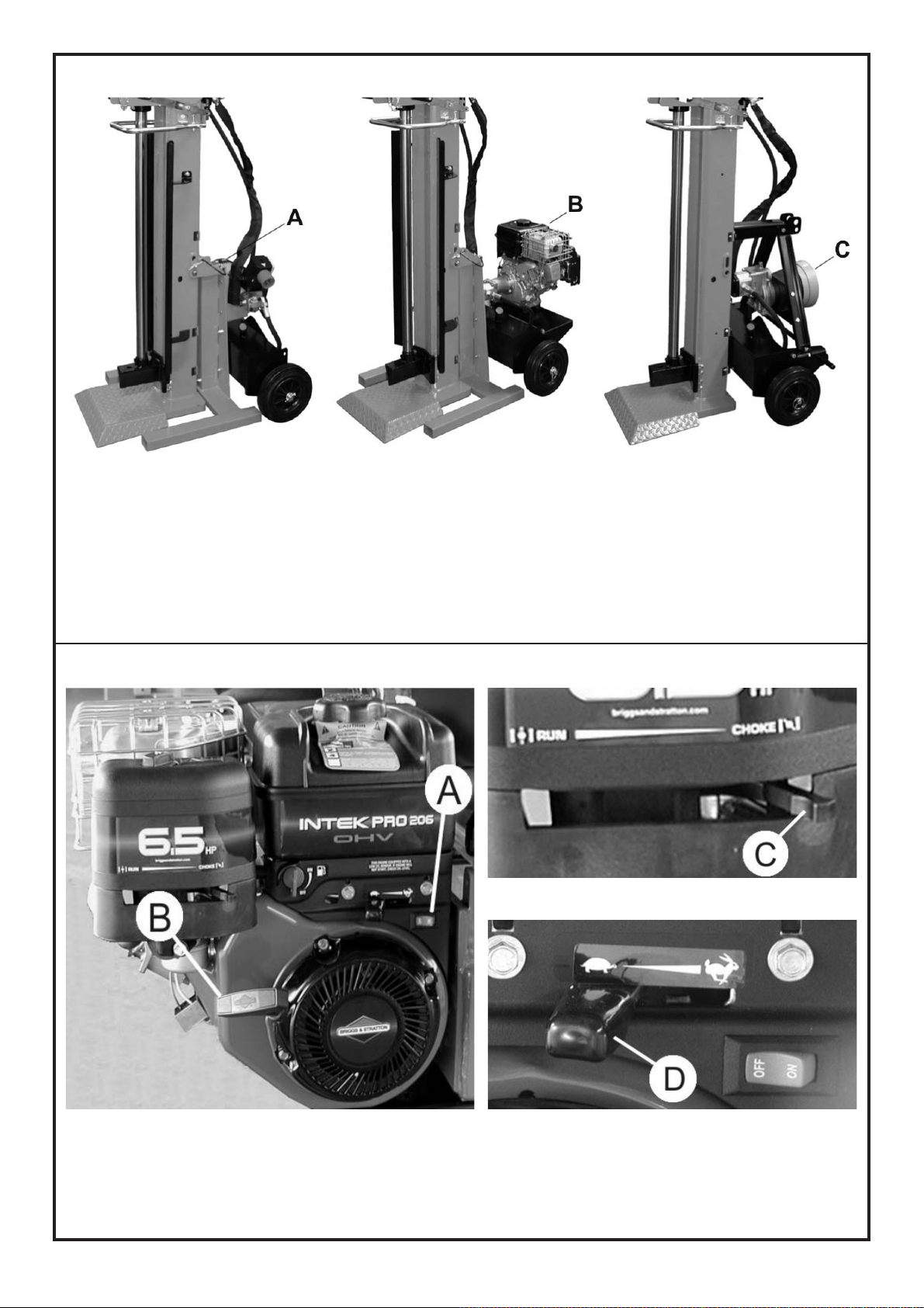
SPL 910 T SPL 910 SC SPL 910 PTO
8d 8e
8f
4
D22001956 - v.0 - UPD 020210
Page 5
9a 9b
10 11
D22001956 - v.0 - UPD 020210
5
Page 6
12b12a
13 14
6
D22001956 - v.0 - UPD 020210
Page 7

INDICE
INTRODUZIONE ....................................................................................................................................................................................................................................... 9
1 DESCRIZIONE DELLA MACCHINA ......................................................................................................................................................................................................... 9
1.1 Iconografia ....................................................................................................................................................................................................................................10
2 CARATTERISTICHE TECNICHE .............................................................................................................................................................................................................. 11
2.1 Corretto modo per sollevare la macchina ..................................................................................................................................................................................... 11
2.2 Dimensioni del legno da rompere .................................................................................................................................................................................................. 11
2.3 Spiegazione etichetta matricola .................................................................................................................................................................................................... 11
3 SICUREZZA .............................................................................................................................................................................................................................................12
3.1 Regole generali di sicurezza ..........................................................................................................................................................................................................12
3.1.A Per macchine con motore elettrico (SPL 910 T - fig.8a) ..............................................................................................................................................................13
3.1.B Per macchine con motore a scoppio (SPL 910 SC - fig.8b).........................................................................................................................................................13
3.1.C Per macchine azionate da albero cardanico (SPL 910 PTO - fig.8c) ............................................................................................................................................13
3.2 Abbigliamento protettivo di sicurezza ............................................................................................................................................................................................ 13
4 MESSA IN FUNZIONE .............................................................................................................................................................................................................................14
4.1.A Per macchine con motore elettrico (SPL 910 T) ...........................................................................................................................................................................14
4.1.B Per macchine con motore a scoppio (SPL 910 SC) .....................................................................................................................................................................14
4.1.C Per macchine azionate da albero cardanico (SPL 910 PTO).........................................................................................................................................................14
4.2 Apertura del cilindro.......................................................................................................................................................................................................................15
4.3 Illuminazione ..................................................................................................................................................................................................................................15
5 USO ..........................................................................................................................................................................................................................................................15
5.1.A Accensione e spegnimento dello spaccalegna elettrico (SPL 910 T)............................................................................................................................................15
5.1.B Accensione e spegnimento dello spaccalegna con motore a scoppio (SPL 910 SC)...................................................................................................................15
5.1.C Accensione e spegnimento degli spaccalegna azionati da trattore (SPL 910 PTO)...................................................................................................................... 16
5.2 Uso dello spaccalegna ..................................................................................................................................................................................................................16
5.3 Utilizzo della tavola mobile (Optional) ...........................................................................................................................................................................................16
5.4 Chiusura del cilindro per il trasporto..............................................................................................................................................................................................16
5.5 Movimentazione manuale dello spaccalegna ................................................................................................................................................................................17
6 MANUTENZIONE ORDINARIA .................................................................................................................................................................................................................17
6.1 Sostituzione dell'olio idraulico ........................................................................................................................................................................................................17
6.2 Olii consigliati ................................................................................................................................................................................................................................ 17
6.3 Affilatura della lama ......................................................................................................................................................................................................................17
7 INCONVENIENTI E RIMEDI ....................................................................................................................................................................................................................18
7.1 Riarmo della protezione termica del motore elettrico ....................................................................................................................................................................18
DEMOLIZIONE E SMALTIMENTO DELLA MACCHINA............................................................................................................................................................................18
PARTI DI RICAMBIO ................................................................................................................................................................................................................................18
CERTIFICATO DI GARANZIA ...................................................................................................................................................................................................................19
ATTENZIONE
All'atto della consegna della macchina assicuratevi che non vi siano parti mancanti o danneggiate durante il trasporto. Eventuali reclami devono essere
notificati immediatamente al trasportatore e al rivenditore. Non verranno riconosciuti reclami ricevuti successivamente.
INDEX
INTRODUCTION ......................................................................................................................................................................................................................................21
1 DESCRIPTION OF THE MACHINE..........................................................................................................................................................................................................21
1.1 Symbols used ...............................................................................................................................................................................................................................22
2 TECHNICAL DAT A ....................................................................................................................................................................................................................................23
2.1 Right way to lift the machine........................................................................................................................................................................................................23
2.2 Size of the logs to be split ............................................................................................................................................................................................................ 23
2.3 Explication of serial number label .................................................................................................................................................................................................23
3 SAFETY ..................................................................................................................................................................................................................................................... 24
3.1 General safety regulations ...........................................................................................................................................................................................................24
3.1.A For machines with electric motor (SPL 910 T - fig.8a) ................................................................................................................................................................25
3.1.B For machines with premium graded fuel engine (SPL 910 SC - fig.8b) ....................................................................................................................................... 25
3.1.C For machines driven by cardan shaft (SPL 910 PTO - fig.8c) ....................................................................................................................................................25
3.2 Safety protective clothing ............................................................................................................................................................................................................25
4 OPERATING THE MACHINE .................................................................................................................................................................................................................... 26
4.1.A For machines with electric motor (SPL 910 T) .............................................................................................................................................................................. 26
4.1.B For machines with premium graded fuel engine (SPL 910 SC) ....................................................................................................................................................26
4.1.C For machines driven by cardan shaft (SPL 910 PTO) .................................................................................................................................................................26
4.2 Opening the cylinder .....................................................................................................................................................................................................................27
4.3 Lighting ..........................................................................................................................................................................................................................................27
5 USE .......................................................................................................................................................................................................................................................... 27
5.1.A Switching on/off of the electric log splitter (SPL 910 T) ............................................................................................................................................................... 27
5.1.B Switching on/off of the log splitter with premium graded fuel engine (SPL 910 SC) ................................................................................................................... 27
5.1.C Switching on/off of the tractor-driven log splitter (SPL 910 PTO) ................................................................................................................................................28
5.2 How to use log splitter ..................................................................................................................................................................................................................28
5.3 Use of the movable table (Optional) ............................................................................................................................................................................................28
5.4 Closing the cylinder for transport .................................................................................................................................................................................................28
5.5 Manual handling of the log splitter ................................................................................................................................................................................................29
6 ROUTINE MAINTENANCE .......................................................................................................................................................................................................................29
6.1 How to change the hydraulic oil ....................................................................................................................................................................................................29
6.2 Recommended oils .......................................................................................................................................................................................................................29
6.3 Sharpening the wedge ...................................................................................................................................................................................................................29
7 TROUBLESHOOTING..............................................................................................................................................................................................................................30
7.1 Resetting of the thermal cut-out of the electric motor .................................................................................................................................................................30
SCRAPPING AND DISPOSAL OF THE MACHINE ..................................................................................................................................................................................30
SPARE P ARTS ........................................................................................................................................................................................................................................... 30
WARRANTY CERTIFICATE.......................................................................................................................................................................................................................31
WARNING
When the machine is delivered, check for any missing parts and for any damage during transport. Any complaints must be forwarded immediately to
the carrier and to the retailer. Any subsequent complaints will not be accepted.
D22001956 - v.0 - UPD 020210
7
Page 8

ALLGEMEINES INHALTSVERZEICHNIS
EINLEITUNG ............................................................................................................................................................................................................................................ 33
1 MASCHINENBESCHREIBUNG ...............................................................................................................................................................................................................33
1.1 Aufschlüsselung der Warnhinweise ..............................................................................................................................................................................................34
2 TECHNISCHE EIGENSCHAFTEN ...........................................................................................................................................................................................................35
2.1 Richtige Weise, um die Maschine zu heben ................................................................................................................................................................................. 35
2.2 Maße des Spaltklotzes ..................................................................................................................................................................................................................35
2.3 Erklärung des Seriennummeraufklebers .......................................................................................................................................................................................35
3 SICHERHEIT ............................................................................................................................................................................................................................................ 36
3.1 Allgemeine Sicherheitsvorschriften ..............................................................................................................................................................................................36
3.1.A Für Maschinen mit Elektromotor (SPL 910 T - fig.8a) .................................................................................................................................................................. 37
3.1.B Für Maschinen mit Benzinmotor (SPL 910 SC - fig.8b) ................................................................................................................................................................37
3.1.C Für Maschinen mit Kardanwellenantrieb (SPL 910 PTO - fig.8c) ..................................................................................................................................................37
3.2 Sicherheits- / Schutzkleidung ........................................................................................................................................................................................................37
4 INBETRIEBSETZUNG .............................................................................................................................................................................................................................38
4.1.A Für Maschinen mit Elektromotor (SPL 910 T) ...............................................................................................................................................................................38
4.1.B Für Maschinen mit Benzinmotor (SPL 910 SC).............................................................................................................................................................................38
4.1.C Für Maschinen mit Kardanwellenantrieb (SPL 910 PTO)...............................................................................................................................................................38
4.2 Aufwärtshub des Zylinders ...........................................................................................................................................................................................................39
4.3 Beleuchtung ..................................................................................................................................................................................................................................39
5 EINSATZ DES HOLZSP A L TERS...............................................................................................................................................................................................................39
5.1.A Zu- und Abschalten des Elektrischen Holzspalters (SPL 910 T) ..................................................................................................................................................39
5.1.B Zu- und Abschalten der Holzspalter mit Benzinmotor (SPL 910 SC) ............................................................................................................................................39
5.1.C Zu- und Abschalten der Holzspalter mit Schlepperantrieb (SPL 910 PTO) ...................................................................................................................................40
5.2 Verwendung des Holzspalters ....................................................................................................................................................................................................... 40
5.3 Gebrauch des verstellbaren Tisches (Optional) ............................................................................................................................................................................40
5.4 Abwärtshub des Zylinders für Transportzwecke ...........................................................................................................................................................................40
5.5 Manuelles Handling des Holzspalters............................................................................................................................................................................................41
6 REGELMÄSSIGE WARTUNG ..................................................................................................................................................................................................................41
6.1 Wechsel des Hydrauliköls ............................................................................................................................................................................................................ 41
6.2 Empfohlene Ölsorten .................................................................................................................................................................................................................... 41
6.3 Schleifen des Messers..................................................................................................................................................................................................................41
7 STÖRUNGEN UND DEREN BEHEBUNG ..............................................................................................................................................................................................42
7.1 Rückstellen des Thermoschutzes des E-Motors ........................................................................................................................................................................... 42
VERSCHROTTUNG UND ENTSORGUNG DER MASCHINE .................................................................................................................................................................42
ERSATZTEILE...........................................................................................................................................................................................................................................42
GARANTIE-ZERTIFICAT ...........................................................................................................................................................................................................................43
ACHTUNG
Die Maschine ist sofort nach der Entgegennahme auf Fehlen von Teilen oder Transportschäden zu überprüfen. Etwaige Beanstandungen sind
unverzüglich beim Spediteur oder beim Wiederverkäufer vorzubringen. Nachträgliche Beanstandungen werden nicht in Betracht gezogen.
INDEX
INTRODUCTION ......................................................................................................................................................................................................................................45
1 DESCRIPTION DE LA MACHINE ............................................................................................................................................................................................................ 45
1.1 Iconographie ..................................................................................................................................................................................................................................46
2 CARACTERISTIQUES TECHNIQUES ...................................................................................................................................................................................................... 47
2.1 Correct maniere pour soulever la machine ................................................................................................................................................................................... 47
2.2 Dimensions du bois à débiter........................................................................................................................................................................................................47
2.3 Explication étiquette de numéro de série ......................................................................................................................................................................................47
3 SECURITE................................................................................................................................................................................................................................................48
3.1 Règles générales de sécurité........................................................................................................................................................................................................48
3.1.A Pour les machines équipées d’un moteur électrique (SPL 910 T - Fig.8a) ...................................................................................................................................49
3.1.B Pour machines équipées d’un moteur à explosion (SPL 910 SC - Fig.8b) ...................................................................................................................................49
3.1.C Pour machines actionnées par un joint de Cardan (SPL 910 PTO - Fig.8c) ................................................................................................................................. 49
3.2 Vêtements de protection ...............................................................................................................................................................................................................49
4 MISE EN MARCHE ...................................................................................................................................................................................................................................50
4.1.A Pour les machines équipées d’un moteur électrique (SPL 910 T).................................................................................................................................................50
4.1.B Pour machines équipées d’un moteur à explosion (SPL 910 SC).................................................................................................................................................50
4.1.C Pour machines actionnées par un joint de Cardan (SPL 910 PTO) .............................................................................................................................................. 50
4.2 Ouverture du vérin ........................................................................................................................................................................................................................51
4.3 Éclairage .......................................................................................................................................................................................................................................51
5 MODE D’EMPLOI ..................................................................................................................................................................................................................................... 51
5.1.A Mise en marche et arrêt de la fendeuse de bois avec moteur électrique (SPL 910 T) ................................................................................................................ 51
5.1.B Mise en marche et arrêt de la fendeuse de bois équipées d’un moteur à explosion (SPL 910 SC).............................................................................................51
5.1.C Mise en marche et arrêt de la fendeuse de bois actionnées par un joint de Cardan (SPL 910 PTO) ................................. ......................................................... 52
5.2 Mode d’emploi de la fendeuse de bois .......................................................................................................................................................................................... 52
5.3 Utilisation de la table mobile (Optional).........................................................................................................................................................................................52
5.4 Verrouillage du vérin pour le transport ..........................................................................................................................................................................................52
5.5 Manutention de la fendeuse de bois ............................................................................................................................................................................................. 53
6 ENTRETIEN ORDINAIRE.........................................................................................................................................................................................................................53
6.1 Remplacement de l’huile hydraulique ........................................................................................................................................................................................... 53
6.2 Huiles conseillées ......................................................................................................................................................................................................................... 53
6.3 Affilage de la lame ........................................................................................................................................................................................................................ 53
7 INCONVENIENTS ET SOLUTIONS ......................................................................................................................................................................................................... 54
7.1 Réarmement de la protection thermique du moteur électrique .....................................................................................................................................................54
DEMANTELEMENT ET ELIMINATION DE LA MACHINE .........................................................................................................................................................................54
PIECES DE RECHANGE .........................................................................................................................................................................................................................54
CERTIFICAT DE GARANTIE.....................................................................................................................................................................................................................55
ATTENTION
Au moment de la livraison de la machine veuillez vous assurer qu'il n'y à pas des parties manquantes ou dommagées pendant le transport. Eventuelles
réclamations doivent être notifiées immediatement au transporteur et au revendeur. Réclamations tardives ne seront pas acceptées.
8
D22001956 - v.0 - UPD 020210
Page 9

ITALIANO
ISTRUZIONI ORIGINALI
INTRODUZIONE
Le macchine spaccalegna EMAK sono state progettate e costruite conformemente alle più recenti normative europee in fatto di sicurezza con
particolare riferimento alle normative EN 609-1 e CEI EN 60204-1.
I sistemi di comando a due mani, infatti, sono stati studiati al fine di obbligare l’operatore a manovrare l'azionamento della macchina soltanto dalle zone
consentite, impiegando entrambe le mani ed escludendo ogni possibile intromissione degli arti in zone pericolose.
Questa macchina spaccalegna è prodotta conformemente alle prescrizioni contenute nella direttiva RoHS 2002/95/CE
Prima di movimentare, installare e rendere operativa la macchina, leggete attentamente questo manuale poichè vi sono contenute
importanti regole per lavorare in sicurezza.
Se l’operatore non fosse in grado di capire una delle lingue del presente libretto, sarà suo compito richiedere la traduzione nella propria lingua al
rivenditore.
L’operatore dovrà altresì addestrare ogni altra persona abilitata all’uso della macchina.
Ogni inosservanza, uso improprio della macchina, manutenzione straordinaria non effettuata da personale specializzato ed autorizzato, la rimozione di etichette di ogni tipo, la rimozione o la manomissione delle protezioni e delle sicurezze e comunque ogni
altra azione non espressamente autorizzata volta ad inficiare le sicurezze attive e passive della macchina fa decadere ogni
responsabilità del costruttore e può causare gravi danni alle persone e alle cose.
La manomissione della macchina da parte di personale non autorizzato fa decadere automaticamente la garanzia.
Il presente libretto è parte integrante della macchina e dovrà sempre accompagnarla anche in caso di passaggio di proprietà o di
prestito sotto qualunque formula.
ATTENZIONE
Il sistema di alimentazione della vostra macchina, produce un campo elettromagnetico di intensità molto bassa. Questo campo
può interferire con alcuni pacemaker. Per ridurre il rischio di lesioni gravi o mortali, le persone con pacemaker dovrebbero
consultare il proprio medico e il costruttore del pacemaker prima di utilizzare questa macchina.
1 - DESCRIZIONE DELLA MACCHINA
Questa serie è formata da spaccalegna verticali trasportabili dotati di motorizzazione propria elettrica oppure di aggancio esterno per azionamento da
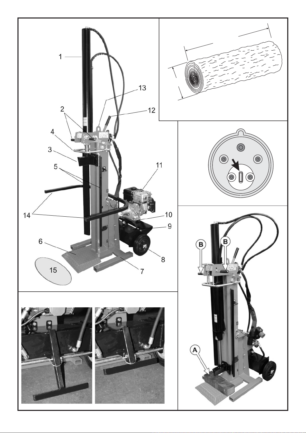
trattore. In fig.1, pag. 2, sono illustrate le varie parti della macchina.
1 - Cilindro
2 - Leve del comando a due mani
3 - Lama
4 - Anello bloccaggio tronco
5 - Guide appoggia tronco
6 - Piano di lavoro
7 - Supporto inclinabile
8 - Ruote per piccoli spostamenti
9 - Serbatoio olio
10 - T appo riempimento olio
11 - Motore elettrico
12 - Leva movimentazione macchina
13 - Punto di sollevamento
14 - Bracci sostegno ceppi
15 - ZONA DI LAVORO CONSENTIT A E OBBLIGA TORIA
D22001956 - v.0 - UPD 020210
9
Page 10
ITALIANO
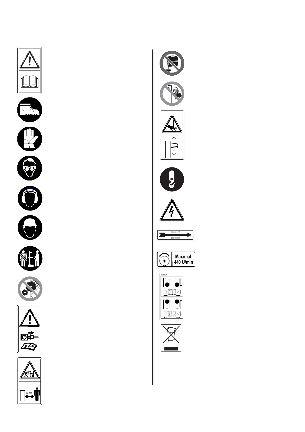
1.1 - Iconografia
Sulla macchina sono riportate segnalazioni grafiche normalizzate al fine di garantire la massima sicurezza relativamente a tutte le parti dello spaccalegna.
Per l’importanza di tali segnalazioni vi preghiamo di leggere attentamente quanto segue.
É vietato scaricare l’olio esausto nell’ambiente. L’olio
Leggere attentamente l’intero libretto di uso e manutenzione della macchina prima della messa in funzione.
Al fine di evitare schiacciamenti dei piedi durante le
normali operazione di carico e scarico dei ceppi di
legno, è obbligatorio indossare adeguate calzature di
protezione.
deve essere smaltito secondo le leggi in vigore nel
paese in cui viene effettuata tale operazione.
Pericolo: non tentare di sbloccare un ceppo incastrato nella lama usando le mani.
Per riparare le mani da schegge di legno o urti contro
la macchina è obbligatorio indossare adeguati guanti a
protezione di entrambe le mani.
Per riparare gli occhi da schegge che possono prodursi durante l'operazione di rottura del ceppo, è obbligatorio indossare adeguati occhiali protettivi.
Per evitare danni acustici causati da una lunga esposizione dell’operatore alle fasi lavorative, alcune delle
quali con livelli di rumore rilevanti, si dovranno indossare apposite cuffie antirumore.
Contro eventuali urti al capo è obbligatorio indossare
un casco che lo ripari adeguatamente.
Lo spaccalegna deve essere utilizzato da una sola
persona.
Pericolo di taglio e schiacciamento della mano: non
toccare mai le zone a rischio durante il movimento
della lama.
Punto di aggancio
Pericolo: tensione elettrica come indicato da targhetta.
Senso di rotazione del motore. In caso di rotazione errata seguite le istruzioni riportate nel paragrafo 4.1.A, pag.14.
Il senso di rotazione dell'albero del cardano deve
essere come indicato nell'etichetta e non deve
superare i 440 giri al minuto.
10
É vietato rimuovere o manomettere le protezioni e i
dispositivi di sicurezza.
Pericolo: prima di effettuare qualsiasi intervento di manutenzione descritto nel presente libretto, staccare la
spina della macchina.
É vietato sostare nel raggio di azione della macchina
quando questa è in moto. Nessuna persona o animale
può sostare in un raggio di cinque metri dalla macchina durante il normale funzionamento della stessa.
Comando a due mani: premendo entrambe le leve
contemporaneamente verso il basso, la lama si aziona
conficcandosi nel tronco.
Una volta spaccato il tronco, spingere verso l'alto le
leve per far tornare la lama nella posizione superiore,
pronta per un nuovo ciclo.
Le macchine dotate di apparecchiature elettriche non
devono essere smaltite come rifiuti misti, ma attraverso una raccolta differenziata separata, presso i punti
autorizzati.
B93250240
D22001956 - v.0 - UPD 020210
Page 11

ITALIANO
2 - CARATTERISTICHE TECNICHE
SPL 910 T SPL 910 SC SPL 910 PTO
INCLINABILE INCLINABILE VERTICALE
Lunghezza (mm) 950 1090 940
Larghezza (mm) 740 740 740
Altezza (mm) 2470 2470 2460
Peso (Kg) 194 197 178
Spinta massima (tons.) 9 9 9
Lunghezze di taglio (mm) 470 / 1070 470 / 1070 470 / 1070
Quantità totale olio (lt.) 13 13 13
Alimentazione 400V 50Hz Trifase Benzina Attacco a cardano
Assorbimento 7,4A —— ——
Potenza 4CV - 3kW 6,5CV - 4,8kW ——
Rumore ≤ 85 dB (A) misurati all'altezza dell'orecchio dell'operatore in posizione di lavoro, a macchina operante.
• Sono obbligatorie adeguate protezioni per le orecchie (cuffie antirumore).
• Nel caso di macchine collegate al trattore, il loro rumore diventa insignificante rispetto a quello generato dal trattore stesso.
2.1 - Corretto modo per sollevare la macchina
La macchina deve essere sollevata e spostata utilizzando un gancio di sollevamento con portata superiore a 300 Kg che deve essere applicato nel
punto di sollevamento (13 in fig.1, pag.2)
2.2 - Dimensioni del legno da rompere
In figura 2 a pag. 2 sono indicate le misure massime dei tronchi da rompere.
Il diametro del legno è indicativo: un tronco di piccole dimensioni può risultare difficoltoso da rompere se contiene nodosità oppure se è formato da fibra
particolarmente attorcigliata.
2.3 - Etichetta matricola
Tipo di macchina:
SPACCALEGNA
Numero di serie
Marchio CE
di conformità
Marchio o
modello macchina
D22001956 - v.0 - UPD 020210
Dati tecnici
N.giri/min
(motore elettrico / giunto cardanico)
11
Page 12

ITALIANO
3 - SICUREZZA
É estremamente importante leggere quanto riportato in questo capitolo. Esso contiene la descrizione dei possibili rischi generati
dall’uso della macchina e le relative informazioni atte a consentire un uso corretto della stessa ed evitare danni alle persone, agli
animali e alle cose.
ATTENZIONE
Questo spaccalegna è stato progettato e costruito al solo scopo di rompere ceppi di legno che non superino le
dimensioni raccomandate in fig.2, pag.2.
Ogni altro uso è da ritenersi improprio ed il costruttore non risponde in alcun modo di eventuali danni a persone, animali od oggetti
causati da un uso erroneo o improprio della macchina.
É obbligatorio che l’operatore agisca soltanto dalla posizione indicata in fig.1 (pos.14) e che il comando di azionamento della macchina (2 in fig.1) venga
manovrato con entrambe le mani, senza ricorrere ad espedienti diversi e senza manomettere i comandi stessi.
In fase di lavoro, a parte l'operatore, non è consentita la presenza di persone ed animali ad una distanza inferiore ai 5 metri dalla macchina.
NON TENTARE DI MANOMETTERE LE PROTEZIONI DELLO SP ACCALEGNA O DI LA VORARE SENZA DI ESSE.
IL MANCATO RISPETTO DI QUANTO RIPORTATO IN QUESTO CAPITOLO PUÒ CAUSARE GRAVI DANNI ALLE PERSONE E AGLI OGGETTI
NONCHÉ ALLA MACCHINA STESSA.
ATTENZIONE
Non utilizzare lo spaccalegna per spezzare materiali lapidei (sassi, cemento, ecc.) né per schiacciare pezzi o contenitori in metallo.
3.1 - Regole generali di sicurezza
• La macchina deve essere usata da un solo operatore.
• Non usare la macchina all’esterno quando piove o nevica.
• Non si deve permettere l’uso dello spaccalegna a terzi se questi non ha letto il manuale di uso e manutenzione o se non è stato istruito sulle regole
da seguire per un corretto e sicuro uso.
• L'uso dello spaccalegna da parte di apprendisti di età comunque non inferiore a 16 anni deve avvenire sotto la supervisione di un maggiorenne
abilitato all'uso.
• Non si devono indossare indumenti larghi o sbottonati o comunque che possano rimanere impigliati nelle parti in movimento della macchina.
• Muovere o spostare lo spaccalegna solo ad alimentazione spenta.
• Non usare le mani per cercare eventuali perdite di olio. Usare sempre un pezzo di carta o di legno.
Getti di olio sotto pressione possono penetrare sotto pelle. In questo caso, farsi subito visitare da un medico.
• Non si deve operare su un terreno in pendenza, accidentato o sdrucciolevole. Posizionate la macchina su un piano ben livellato e libero da oggetti
che possano impedire la piena libertà d’azione e di lavoro per l’operatore. Bloccare la macchina in modo ben stabile.
• Controllate che i tronchi da spaccare siano privi di nodosità, chiodi, viti o fili di ferro che possono essere lanciati violentemente verso le persone
durante il taglio. Le estremità dei tronchi devono essere tagliate in squadro. I rami devono essere tranciati a filo del tronco.
• Non tentate di tagliare ceppi di dimensioni superiori a quelle indicate in fig.2, pag.2: potrebbe essere pericoloso e si potrebbe danneggiare la
macchina.
• Posizionate il tronco in modo che venga spaccato nella direzione delle fibre. Diversamente può risultare pericoloso e può compromettere il
funzionamento della macchina.
• Non cercate di tagliare due tronchi contemporaneamente: uno potrebbe essere sbalzato via colpendovi.
• Se il tronco tende a scivolare via dalla lama, ritrarre lo spingitronco o la lama e ruotare il tronco di 90°
• Non caricate il tronco mentre la macchina è in funzione: potreste impigliarvi e rimanere feriti.
• Tenete le dita lontano dalle fenditure e dalle crepe che si formano sul tronco: queste potrebbero chiudersi improvvisamente causando gravi
schiacciature o addirittura amputazioni.
• Non forzate lo spaccalegna per più di 30 secondi, tenendo il cilindro in pressione o provando a rompere legna troppo dura. Trascorso tale tempo,
infatti, l’olio sotto pressione si surriscalda e la macchina potrebbe danneggiarsi.
• Non lasciate la macchina incustodita. Se dovete abbandonare il luogo di lavoro, togliete la fonte di alimentazione e fate attenzione a qualsiasi
possibile rischio di accensione accidentale.
• Non usate mai lo spaccalegna sotto l'influenza di alcoolici, droghe, farmaci o se siete particolarmente stanchi. La lucidità è sostanziale per la
sicurezza ed una distrazione potrebbe causare incidenti anche gravi.
• Non tentate di disincastrare i ceppi bloccati mentre la macchina è in moto: durante tale operazione la macchina deve essere spenta.
• Non fatevi aiutare da terzi per disincastrare un ceppo bloccato.
• Non utilizzate alcol, benzina o solventi per pulire la macchina. La leggibilità delle informazioni di sicurezza, applicate alla macchina stessa, potrebbe
essere pregiudicata irrimediabilmente.
• Prima di iniziare a familiarizzare e ad usare la macchina, attenersi alle disposizioni di legge previste nel paese di utilizzo per quanto concerne l’età
minima dell’operatore, che deve avere un grado di istruzione adeguato.
• Qualsiasi tipo di verifica, controllo, pulizia, manutenzione, cambio e sostituzione pezzi, deve essere effettuata con spaccalegna spento e spina
staccata dalla presa di corrente, per i modelli a funzionamento elettrico e con trattore spento e cardano staccato per il modello con trasmissione
a mezzo presa di forza.
12
D22001956 - v.0 - UPD 020210
Page 13

ITALIANO
3.1.A - Per macchine con motore elettrico (SPL 910 T - fig.8a)
• Non usate la macchina in presenza di gas naturale, vapori di benzina o altri vapori infiammabili.
• Verificate che l’impianto elettrico che alimenterà la macchina sia idoneo.
Dovranno essere controllate tensione, frequenza di rete e potenza erogata (verificate la targhetta sul motore ed i dati nel presente manuale). La
macchina dovrà essere collegata ad un impianto dotato di salvavita differenziale adatto e in rispetto alle normative (corrente di guasto
nominale di 30 mA) e dovrà essere presente un adeguato impianto di messa a terra.
• Usate cavi di sezione pari a 2,5 mm
materiale protetto e adatto all'uso per esterno. Non usate prolunghe lunghe oltre 5 metri: cavi eccessivamente lunghi o di sezione
inadeguata possono provocare cadute di tensione che non permettono al motore di sviluppare tutta la sua potenza.
dell'utilizzo verificare sempre che la prolunga sia priva di eventuali danni.
• In mancanza di un salvavita fisso, utilizzare un salvavita portatile.
• Verificate sempre che la macchina e il cavo non vengano a contatto con acqua.
• Onde evitare avviamenti accidentali alla connessione della macchina, verificate che l’interruttore sia in posizione “0”, spento.
• Mai arrestare lo spaccalegna staccando la spina dalla presa di corrente.
• Non tirate il cavo di alimentazione per spostare la macchina, non date strattoni al cavo stesso e tenetelo lontano da fonti di eccessivo calore, olii,
solventi e oggetti taglienti.
• Non utilizzare il cavo per staccare la spina dalla presa.
• Non lasciate mai la macchina incustodita se collegata all’impianto elettrico. Dopo l'utilizzo, la macchina deve essere sempre spenta e scollegata
dalla rete di alimentazione. In particolare quando si deve eseguire qualsiasi intervento di manutenzione.
3.1.B - Per macchine con motore a scoppio (SPL 910 SC - fig.8b)
• Se operate in zone aride prendete adeguate precauzioni al fine di evitare incendi.
• Non fumate durante le fasi di lavoro, durante i rifornimenti di carburante o comunque in prossimità della macchina.
• Non si deve rifornire lo spaccalegna di carburante mentre è in moto. Spegnete il motore, lasciatelo raffreddare ed eseguite il pieno di carburante
facendo attenzione a non far traboccare la benzina. Asciugatene eventuali fuoriuscite prima di mettere in moto.
• Fate attenzione a non toccare il motore e il tubo di scarico poichè diventano caldissimi e possono provocare ustioni.
2
. Non lavorate con connessioni volanti e non opportunamente isolate. I collegamenti devono essere fatti con
Prima
ATTENZIONE
NON A VVIA TE LO SPACCALEGNA IN LOCALI CHIUSI: I GAS DI SCARICO SONO LET ALI.
3.1.C - Per macchine azionate da albero cardanico (SPL 910 PTO - fig.8c)
ATTENZIONE
Utilizzare esclusivamente alberi cardanici marcati CE e attenersi scrupolosamente alle indicazioni di utilizzo del costruttore
• Non fissate mai lo spaccalegna con il trattore in moto.
• Ponete attenzione che lo spaccalegna sia perfettamente fissato ai 3 punti del trattore.
• Ponete la massima attenzione che il cardano sia perfettamente inserito nella presa di forza e che si sia sentito lo scatto di aggancio.
• Non toccate mai il cardano con il motore in moto.
3.2 - Abbigliamento protettivo di sicurezza
Quando si lavora con lo spaccalegna usare sempre un abbigliamento protettivo di sicurezza omologato. L’uso dell’abbigliamento protettivo non elimina
i rischi di lesione, ma riduce gli effetti del danno in caso di incidente.
Fatevi consigliare dal vostro rivenditore di fiducia per la scelta dell’abbigliamento adeguato.
• L’abbigliamento deve essere adatto e non d’impaccio.
• Indossare un abito aderente protettivo. La giacca e la salopette di protezione sono l’ideale. Non portare abiti, sciarpe, cravatte o monili che
potrebbero impigliarsi.
• Raccogliere i capelli lunghi e proteggerli (per esempio con un foulard, un berretto, un casco, ecc.)
• Indossare scarpe di sicurezza munite di suole antisdrucciolo e puntali d’acciaio.
• Indossare gli occhiali o la visiera protettivi!
• Applicare protezioni dai rumori; per esempio le cuffie o i tappi. L’uso delle protezioni per l’udito richiede maggior attenzione e prudenza, perché la
percezione di segnali acustici di pericolo (grida, allarmi, ecc.) è limitata.
• Calzare guanti protettivi.
D22001956 - v.0 - UPD 020210
13
Page 14

ITALIANO
4 - MESSA IN FUNZIONE
Il modello basculante, permette all’operatore di lavorare con la macchina in 4 diverse posizioni: da completamente verticale a completamente orizzontale (fig.7, pag. 3). Per modificare la posizione, togliere il perno di fissaggio, posizionare
la macchina, quindi, reinserire il perno nel foro adatto, fissandolo con la coppiglia a “R” (fig.7)
• Lo spaccalegna, in ottemperanza alla normativa EN 609-1, è azionato da un comando a due mani: la macchina entrerà in funzione solo
azionando entrambe le leve contemporaneamente (2 in fig.1, pag.2).
• Non usate mai lo spaccalegna se non è in perfetta efficienza o se necessita di manutenzione. Prima dell'utilizzo verificate che tutti i dispositivi di
sicurezza (comando di azionamento a due mani, pulsante di spegnimento sulle macchine elettriche) funzionino come previsto.
• Prima di iniziare a lavorare, verificate l'integrità dei tubi flessibili e l'assenza di perdite nei raccordi, controllate il livello dell’olio idraulico nel serbatoio
e, se necessario, rabboccate usando l’olio indicato a pag.17 (par. 6.2)
Il livello dell’olio deve essere compreso fra le due tacche poste sullo stelo del tappo olio (10 in fig.1, pag.2).
• Prima di iniziare a lavorare accendete la macchina e lasciate riscaldare l’olio per alcuni minuti.
4.1.A - Per macchine con motore elettrico (SPL 910 T)
Dopo aver collegato l’alimentazione alla macchina con motore elettrico trifase, verificate il senso di rotazione del motore che deve corrispondere a
quello della freccia posta sul motore stesso. Se il senso di rotazione non coincide, è necessario invertire due poli nella spina.
Togliete la presa dallo spaccalegna quindi inserite un cacciavite con taglio a lama di dimensioni adeguate nella feritoia all'interno della spina dell'interruttore, come indicato in fig.3, pag.2. Premete delicatamente e allo stesso tempo girate di 180° il disco bianco. Con questa operazione si invertono
fisicamente due poli sul motore trifase. Verificate ora che il motore giri effettivamente nel senso corretto indicato dalla freccia.
Non aprite mai la scatola dell’interruttore posta sul motore o la morsettiera. In caso di necessità consulta
te il vostro elettricista di fiducia.
Se saltano i fusibili o le protezioni, significa che si sta sovraccaricando il motore oppure che l’impianto elettrico non è adeguato: consultate il vostro
elettricista di fiducia.
4.1.B - Per macchine con motore a scoppio (SPL 910 SC)
• Prima di azionare lo spaccalegna leggete attentamente il libretto di uso e manutenzione fornito dal costruttore del motore ed allegato al motore
stesso. Prendete visione delle norme di manutenzione e garanzia fornite.
• Controllate il livello dell’olio nel basamento del motore. Se necessario rabboccate con olio consigliato dal costruttore del motore.
ATTENZIONE: lavorare senza olio può causare danni irreparabili al motore.
• All’arrivo della macchina e al primo avviamento è importante lasciar girare a vuoto per almeno 20 minuti il motore. Questo rodaggio assicura un buon
funzionamento di tutto il sistema ed il massimo rendimento.
4.1.C - Per macchine azionate da albero cardanico (SPL 910 PTO)
ATTENZIONE
Utilizzare esclusivamente alberi cardanici marcati CE e attenersi scrupolosamente alle indicazioni di utilizzo del costruttore
• Assicuratevi che il trattore sia spento, che il freno a mano sia tirato e, se necessario che vi siano cunei sotto alle ruote.
• Agganciate lo spaccalegna ai tre punti di presa predisposti.
• Collegate l'albero cardanico al moltiplicatore (C in fig.8c, pag.4) alla presa di forza del trattore. Prestate la massima attenzione che il cardano sia
della misura corretta, che sia dotato di cuffia di protezione e che durante l'aggancio si senta lo scatto di presa.
• Verificate che le leve di azionamento siano in posizione neutra.
• Dopo il collegamento dello spaccalegna, avviate il trattore e verificate che il senso di rotazione del cardano corrisponda a quello riportato nella
relativa etichetta posta sul moltiplicatore (vedi par.1.1 "ICONOGRAFIA").
• Posizionate l'acceleratore del trattore in modo che il motore eroghi una potenza sufficiente da azionare bene lo spaccalegna e comunque
verificate che la presa di forza non superi i 440 giri/min. come riportato sull'etichetta.
ATTENZIONE
É necessario seguire le poche ma importantissime regole citate sopra per evitare inconvenienti che potrebbero causare danni
alle persone o alle cose.
ATTENZIONE
Non toccate mai il cardano o qualunque parte in rotazione: si potrebbero verificare situazioni di gravissimo pericolo per le
persone o per le cose.
14
D22001956 - v.0 - UPD 020210
Page 15

ITALIANO
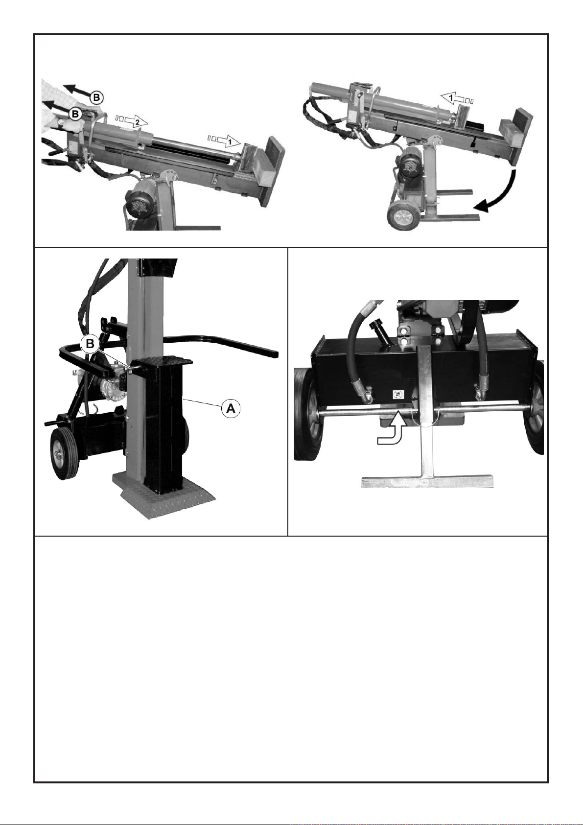
4.2 - Apertura del cilindro
Prima di usare lo spaccalegna è necessario alzare il cilindro come descritto di seguito.
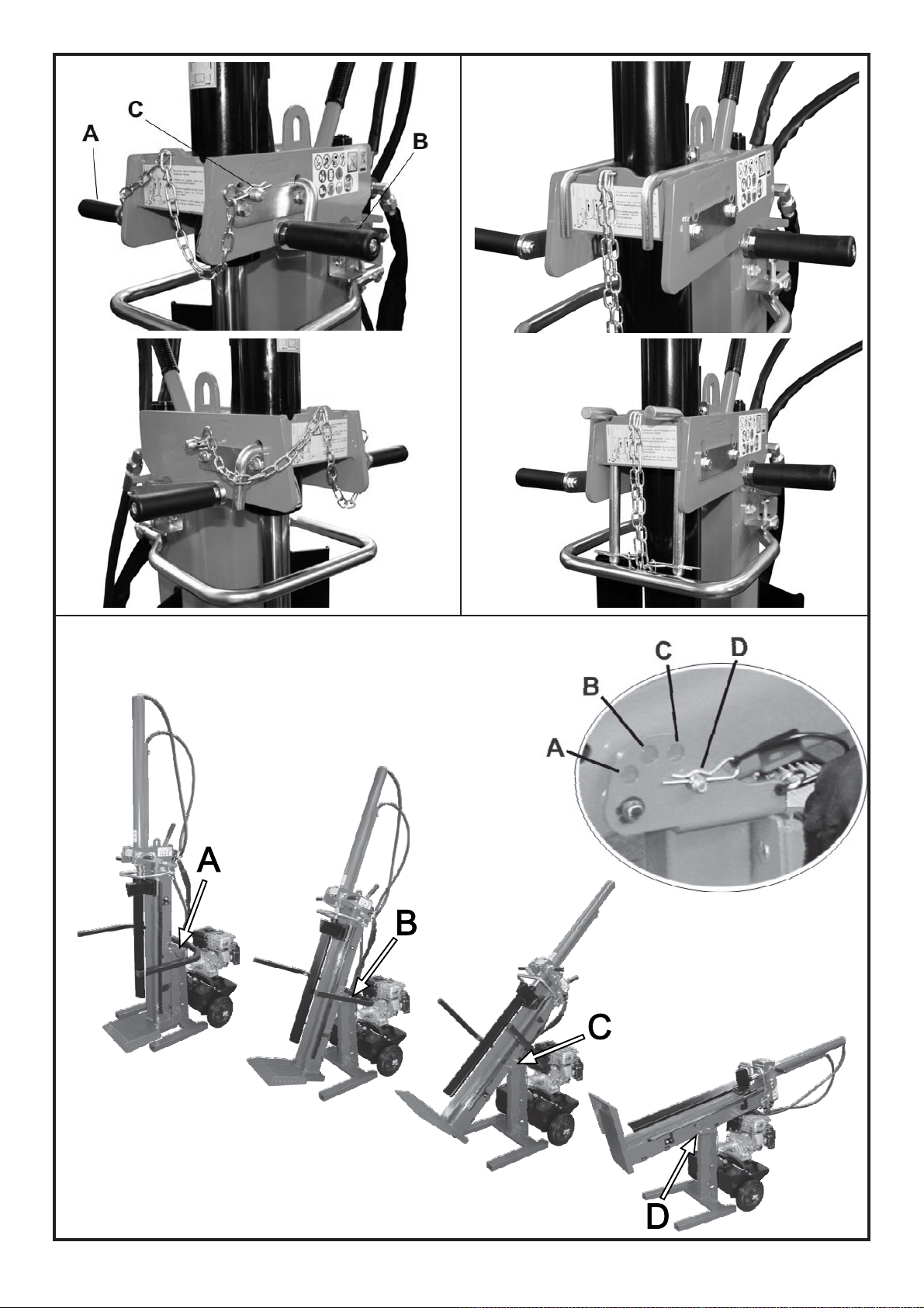
• Togliere i perni di fissaggio dalla posizione di trasporto (fig.6d, pag.3) e appoggiarli negli appositi spazi a i lati del cilindro (fig.6c)
• Posizionare un pezzo di legno sotto alla lama (A in fig.5, pag.2)
• Azionare entrambe le leve di comando dello spaccalegna (B in fig.5, pag.2) portandole verso il basso: si otterrà il sollevamento del cilindro mentre
la lama rimarrà appoggiata al legno.
• Rilasciare la leva destra (B in fig.6a), inserire i perni per il fissaggio del cilindro negli appositi fori e fissarli con la coppiglia a "R" (C in fig.6a).
• Rilasciare anche la leva sinistra (A in fig.6a) quindi spingere verso l'alto entrambe le leve, fino allo scatto. La lama si porterà nella posizione di tutto
aperto, pronta per iniziare a lavorare.
• A fine corsa il dispositivo di arresto (4 in fig.1, pag.2) provvederà automaticamente a riportare la lama in posizione neutra.
ATTENZIONE
È VIETA T O TRASPORT ARE LO SP ACCALEGNA CON IL CILINDRO SOLLEV A T O. IL COSTRUTTORE NON RISPONDE DI DANNI A
PERSONE, ANIMALI O COSE CAUSA TI DAL TRASPORTO DELLO SP ACCALEGNA CON IL CILINDRO ALZA TO.
4.3 - Illuminazione
Tutte le zone della macchina devono essere illuminate in modo da garantire la loro perfetta visibilità durante il lavoro, le operazioni di manutenzione e
le regolazioni. Anche in caso di lavoro in esterni, è indispensabile che vi sia sufficiente luce per poter eseguire il lavoro in sicurezza. È vietato lavorare
durante orari in cui la scarsità di luce può causare una cattiva visibilità della macchina e dei suoi componenti (alba, crepuscolo, notte).
5 - USO
ATTENZIONE:
Non usare la macchina all’esterno quando piove o nevica.
In caso di non utilizzo, immagazzinare la macchina al riparo dagli agenti atmosferici.
5.1.A - Accensione e spegnimento dello spaccalegna elettrico (SPL 910 T)
• Verificate che l'interruttore/salvavita dell'impianto generale e l'interruttore della macchina siano spenti.
• Collegate lo spaccalegna elettrico all'impianto di alimentazione inserendo l'apposita presa nella spina situata sul motore elettrico.
• Prestate attenzione a non far passare il cavo di alimentazione nelle vicinanze della lama o comunque in un posto in cui potrebbe subire danni o
troncarsi.
• Armate l'interruttore generale quindi accendete lo spaccalegna premendo il tasto verde dell'interruttore.
• Usate lo spaccalegna come spiegato nel paragrafo 5.2
• Se vi assentate spegnete lo spaccalegna, premendo il tasto rosso dell'interruttore (spento).
• Terminato il lavoro, togliete alimentazione alla macchina mettendo in posizione "0" (spento) l'interruttore/dif ferenziale dell'impianto generale quindi
estraete la spina dalla presa sulla macchina. Nel compiere tale operazione, non tirate mai il cavo ma prendete il corpo della presa e toglietela.
5.1.B - Accensione e spegnimento dello spaccalegna con motore a scoppio (SPL 910 SC)
Posizionate l'interruttore (A in fig.8d, pag.4) posto sulla parte destra del motore su "ON".
• Portate la levetta del comando farfalla (C in fig.8e, pag.4) su "CHOKE" se il motore è freddo oppure su "RUN" se il motore è ancora caldo.
• Posizionate il pomello dell'acceleratore (D in fig.8f, pag.4) tutto a sinistra (tartaruga).
• Prendete il pomello di avviamento del motore (B in fig.8d) fra le dita e, stringendolo bene, tiratelo con forza, ripetendo l'operazione fino a quando
il motore non si avvia. Fate attenzione durante questa fase, a non cadere e a non procurarvi lesioni o strappi.
Quando il motore si accende, la trave telescopica si porta in posizione di tutto aperto.
• Portate lentamente l'acceleratore (D in fig.8f) verso destra (lepre).
• Dopo pochi minuti dall'accensione a freddo spostate la levetta del comando farfalla (C in fig.8e) da "CHOKE" a "RUN".
• Usate lo spaccalegna come spiegato nel paragrafo 5.2
• Se vi assentate o se avete finito il lavoro, spegnete lo spaccalegna utilizzando l'interruttore A in fig.8d ("OFF").
ATTENZIONE
Durante tutte le fasi di lavoro e dopo lo spegnimento, non toccate alcuna parte del motore perchè potreste scottarvi. Dopo lo
spegnimento attendete che il motore si sia raffreddato prima di compiere qualsiasi operazione.
Per ogni altro riferimento sul motore a scoppio BRIGGS & STRATTON consultate il relativo manuale allegato.
D22001956 - v.0 - UPD 020210
15
Page 16

ITALIANO
5.1.C - Accensione e spegnimento degli spaccalegna azionati da trattore (SPL 910 PTO)
ATTENZIONE
Utilizzare esclusivamente alberi cardanici marcati CE e attenersi scrupolosamente alle indicazioni di utilizzo del costruttore
• Agganciate lo spaccalegna alla relativa fonte di moto (vedi cap.4 "MESSA IN FUNZIONE") quindi assicuratevi che lo spaccalegna sia ben
posizionato a terra.
• Avviate il trattore facendo attenzione a non muoverlo dalla posizione in cui si trova. Mettete in funzione lo spaccalegna azionando il sistema di
alimentazione (presa di forza, cardano, ecc.). La lama si porterà in alto.
• Usate lo spaccalegna come spiegato nel paragrafo 5.2
• Se vi assentate spegnete lo spaccalegna, disattivando il sistema di trasmissione del trattore.
• Dopo l'uso disattivate il sistema di trasmissione, spegnete il trattore quindi, prima di spostare il trattore, sollevate lo spaccalegna ad
un'altezza sufficiente affinchè non batta a terra.
ATTENZIONE
Non mettete in movimento il trattore con la fonte di alimentazione dello spaccalegna azionata o con lo spaccalegna ancora a terra.
5.2 - Uso dello spaccalegna
• Posizionate il ceppo di legno sul piano di lavoro (6 in fig.1, pag.2), centrandolo sotto alla lama. É importante, per una buona sicurezza nel lavoro
che le due facce del tronco siano parallele fra loro e al piano.
• Operando solamente dalla posizione consentita (14 in fig.1, pag.2), azionate entrambe le leve verso il basso (posizione verticale - B in fig.5, pag.3)
o in avanti (posizione orizzontale - B in fig.10, pag.5): la lama si azionerà conficcandosi nel tronco.
• Una volta spaccato il tronco, i ceppi non cadranno perchè verranno trattenuti dai bracci laterali.
• Se il tronco non dovesse rompersi velocemente, oppure se la lama si dovesse fermare, non mantenete la macchina sotto sforzo. Così facendo,
infatti, l'olio nel circuito idraulico si surriscalda molto velocemente danneggiando la pompa. É conveniente far tornare la lama a riposo e riprovare
ruotando il tronco.
• Ripetete l'operazione con i pezzi ottenuti in modo da spaccare il ceppo in più parti. PER ROMPERE TRONCHI CORTI UTILIZZARE LA T AVOLA
MOBILE (FIG . 13, P AG . 6)
• Per far ritornare la lama nella posizione superiore, pronta per un nuovo ciclo di lavoro, dovete spingere verso l'alto entrambe le leve fino a
bloccarle. Le leve rimarranno stabili in questa posizione fino a fine corsa della lama quando il dispositivo di arresto provvederà automaticamente
a riportarle in posizione neutra.
Nota: Se lasciate anche una sola delle leve, la lama si bloccherà nella posizione in cui si trova.
ATTENZIONE
IL COSTRUTTORE DECLINA OGNI RESPONSABILITÀ PER DANNI A PERSONE, ANIMALI O COSE, CAUSA TI DA UN USO IMPROPRIO
DELLA MACCHINA
5.3 - Utilizzo della tavola mobile (Optional)
Lo spaccalegna può montare, a richiesta, una tavola mobile supplementare (fig.13, pag.6) che consente di rompere tronchi corti.
La tavola mobile (A in fig.13) deve essere posizionata sul piano di appoggio tronco e bloccata con il perno in dotazione (B in fig.13) facendo
attenzione ad inserirlo a fondo e a bloccarlo con la coppiglia a "R".
Se si utilizza la tavola mobile è necessario far compiere alla lama solo la corsa necessaria per arrivare fino alla tavola senza toccarla.
ATTENZIONE
Non lavorate con il perno della tavola non perfettamente inserito o non bloccato con la coppiglia a "R".
5.4 - Chiusura del cilindro per il trasporto
Prima di effettuare il sollevamento ed il trasporto dello spaccalegna è necessario abbassare il cilindro come descritto di seguito.
• Posizionare un pezzo di legno sul piano di lavoro (A in fig.5, pag.2) e togliere la coppiglia a R dai perni di fissaggio del cilindro (C in fig.6a, pag.3).
• Azionate entrambe le leve di comando dello spaccalegna (B in fig.5, pag.2) in modo da abbassare completamente la lama (fig.5)
• Rilasciare la leva destra (B in fig.6a) in modo che la lama rimanga nella posizione raggiunta.
• Togliere i perni per il fissaggio del cilindro (C in fig.6a) e sistemarli negli appositi spazi ai lati del cilindro (fig.6c).
• Rilasciare anche la leva sinistra quindi azionare entrambe le leve verso l'alto, fino allo scatto, per far abbassare il cilindro
• Quando il cilndro è completamente rientrato e la lama sollevata dal pezzo di legno, riportate le leve in posizione neutra
• Inserire i perni di fissaggio del cilindro negli appositi spazi per il trasporto e fissarli con la coppiglia a R (fig.6d, pag.3).
Ora lo spaccalegna può essere trasportato.
ATTENZIONE
È VIET A TO TRASPORT ARE LO SP ACCALEGNA CON IL CILINDRO SOLLEV AT O. IL COSTRUTTORE NON RISPONDE DI DANNI A
PERSONE, ANIMALI O COSE CAUSA TI DAL TRASPORTO DELLO SP ACCALEGNA CON IL CILINDRO ALZA TO.
16
D22001956 - v.0 - UPD 020210
Page 17

ITALIANO
5.5 - Movimentazione manuale dello spaccalegna
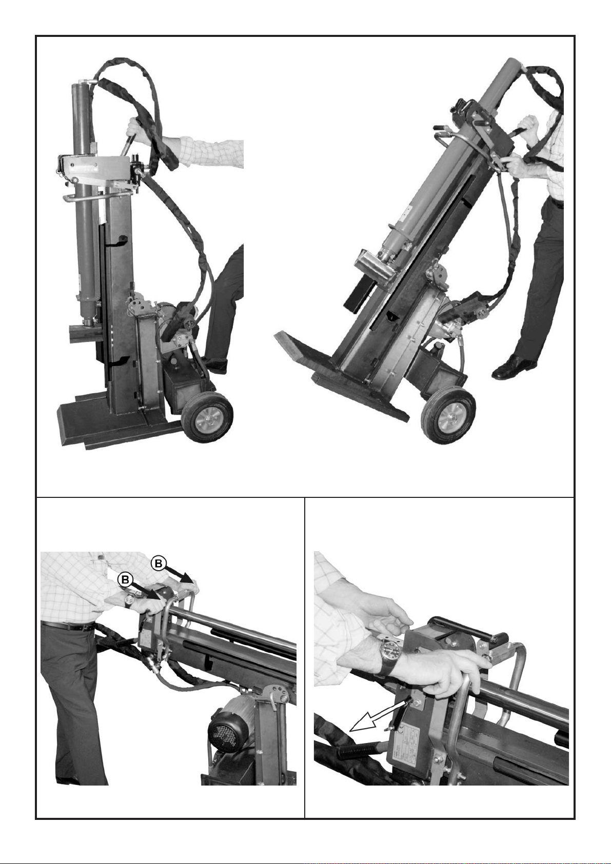
Prima di movimentare lo spaccalegna, è necessario abbassare il cilindro (1 in fig.1, pag.2) e sollevare il piede (fig.4, pag.2).
Per una movimentazione comoda e sicura fate uso dell'apposita leva posta nella parte alta della trave (12 in fig.1, pag.2).
• Puntate un piede sul basamento dello spaccalegna (fig.9a, pag.5) quindi tirando il maniglione, sbilanciate la macchina verso di voi (fig.9b, pag.5)
in modo da poterla spostare comodamente.
• Per appoggiarla, rimettete un piede sul basamento e posatela delicatamente a terra.
ATTENZIONE
SPOSTANDO MANUALMENTE LO SP ACCALEGNA F ATE P ARTICOLARE ATTENZIONE A MANTENERE IL CORRETTO EQUILIBRIO ED
EVIT ARE IL ROVESCIAMENTO DELLA MACCHINA. NON TIRA TE LA LEV A VIOLENTEMENTE VERSO DI VOI. ASSICURA TEVI CHE IL
PERCORSO DI SPOSTAMENT O SIA PIANO E LIBERO DA OSTACOLI.
6 - MANUTENZIONE ORDINARIA
In questo capitolo vengono descritte le operazioni di manutenzione ordinaria, pertanto quelle effettuate dall'operatore, sullo spaccalegna al fine di
mantenerlo sempre in perfetta efficienza e quindi affidabile per un uso continuativo e duraturo.
Ogni operazione di manutenzione ordinaria deve essere compiuta a macchina spenta e, nel caso di spaccalegna ad alimentazione elettrica, con il cavo
di alimentazione disconnesso.
Ogni altra operazione di manutenzione non specificatamente contemplata in questo manuale deve essere effetuata da personale
specializzato in quanto si possono creare situazioni di pericolo sulle quali l'operatore non è preparato.
Ogni operazione di manutenzione straordinaria o sostituzione di parti di ricambio non effetuate da personale specializzato, fanno
immediatamente decadere la garanzia e sollevano il costruttore da qualsiasi responsabilità per danni a persone, animali o cose.
6.1 - Sostituzione dell'olio idraulico
Ogni 600 ore di lavoro è necessario sostituire l'olio esausto con altro olio nuovo del tipo riportato nel paragrafo seguente.
Per sostituire l'olio procedete come segue.
• Assicuratevi che la lama sia completamente rientrata.
• Mettete sotto al tappo di scarico olio, situato sotto al serbatoio dell'olio (fig.14, pag.6), una vaschetta di raccolta che possa contenere circa 15 litri
di olio.
• Svitate il tappo di scarico con una chiave adatta e lasciate scendere nella vaschetta tutto l'olio contenuto nel serbatoio.
• Quando il serbatoio è completamente svuotato, pulite l'imbocco e il tappo di scarico con benzina, quindi riavvitate il tappo di scarico a fondo.
Fate riferimento alla tabella riportata a pag.11 per sapere la quantità corretta di olio quindi procedete come segue:
• Sfilate il tappo dell'olio (10 in fig.1, pag.2), riempite il serbatoio con olio adatto (paragrafo 6.2 "Olii consigliati") e verificate con l'astina di livello che
vi sia la giusta quantità.
• Pulite l'imbocco del tappo dell'olio e reinserite il tappo.
• Mettete in funzione lo spaccalegna e fate compiere alla lama alcune corse per far uscire eventuali bolle d'aria dal circuito.
Alla fine, riportate la lama nella sua posizione di partenza, in alto, pronta per un nuovo ciclo di lavoro.
ATTENZIONE:
NON GETTA TE L'OLIO ESAUSTO FRA I RIFIUTI GENERICI! L'OLIO ESAUSTO DEVE ESSERE SMALTIT O SECONDO LE PRESCRIZIONI
DI LEGGE IN VIGORE NEL P AESE DI UTILIZZO DELLA MACCHINA.
6.2 - Olii consigliati
Vi consigliamo di usare i seguenti tipi di olio per il cilindro idraulico:
SHELL TELLUS T22
ARAL VITAM GF22
BP ENERGOL HCP22
TEXACO RANDO HDZ 22/32
MOBIL DTE1 1 o equivalenti.
NON USATE OLII CON GRADAZIONI DIFFERENTI.
6.3 - Affilatura della lama
Dopo numerose ore di lavoro e comunque in caso di bisogno, affilate la lama dello spaccalegna usando una lima a denti fini e facendo attenzione ad
asportare anche eventuali bave o schiacciature del metallo.
D22001956 - v.0 - UPD 020210
17
Page 18

ITALIANO
7 - INCONVENIENTI E RIMEDI
La seguente tabella riporta i possibili problemi che possono verificarsi durante l'uso dello spaccalegna ed i relativi rimedi consigliati.
Ogni intervento da parte di personale non specializzato fa decadere immediatamente la garanzia della macchina e solleva il costruttore da qualsiasi
responsabilità per danni causati alle persone, agli animali e alle cose.
Problema
Il tronco non si spacca
Lo stelo avanza a scatti o con forti vibrazioni. Esce olio schiumoso dal tappo di riempimento.
Perdita di olio dai raccordi, dalla pompa o
dal cilindro
Probabile causa
Il tronco è di dimensioni più grandi di quelle
consentite
Errato posizionamento del tronco
La lama non taglia
Perdita di olio
Pressione idraulica troppo bassa
Presenza di aria nel circuito
Raccordi lenti
Guarnizioni usurate
Rimedio
Cercare di tagliarne una piccola parte o ridurre con altri mezzi la dimensione del tronco.
Sistemare correttamente il tronco
Affilare la lama; controllare bave o tacche, li-
mare se necessario
Individuare la perdita usando un pezzo di
carta o di legno. Contattare il rivenditore.
Contattare il rivenditore
Controllare il livello dell'olio e, se necessario,
aggiungerne.
Controllare che la pompa non aspiri aria.
Verificare che, nel tratto di circuitoche va
dal serbatoio alla pompa, i raccordi non
siano lenti o il tubo danneggiato.
Se il problema persiste contattate il
rivenditore.
Stringere i raccordi
Contattare il rivenditore
7.1 - Riarmo della protezione termica del motore elettrico
Durante il lavoro con macchine alimentate elettricamente, nel caso di un sovraccarico, uno sbalzo molto forte di tensione oppure un guasto accidentale
all'impianto elettrico, interverrà un dispositivo di protezione applicato al motore e integrato nell'interruttore generale. in caso di intervento della protezione, prima di chiamare il centro di assistenza autorizzato, attendete alcuni minuti quindi provate a riarmare l'interruttore generale. Se non si ripresenta il
problema, potete usare la macchina tranquillamente. Se invece la protezione dovesse saltare ancora, non insistete nel tentativo di farla rimanere
agganciata e contattate il centro di assistenza tecnica autorizzata.
DEMOLIZIONE E SMAL TIMENTO DELLA MACCHINA
La demolizione della macchina deve essere eseguita rispettando tutte le norme di sicurezza atte ad evitare danni alle persone, all'ambiente e agli
animali.
Tutte le parti della macchina devono essere rottamate e smaltite secondo le leggi vigenti nel luogo in cui viene effettuata la demolizione.
Particolare attenzione è da porre nello smaltimento dell'olio idraulico e delle apparecchiature elettriche. Entrambe non devono essere dispersi nell'am-
biente in quanto altamente inquinanti, ma devono essere smaltiti secondo le prescrizioni di legge.
Le macchine dotate di apparecchiature elettriche non devono essere smaltite come rifiuti misti, ma attraverso una raccolta differenziata separat a, presso
i punti autorizzati.
Il produttore è impegnato nel riciclaggio dei rifiuti (RAEE) attraverso l'adesione agli appositi consorzi di smaltimento.
Uno smaltimento non conforme alle prescrizioni di cui sopra è sanzionabile a norma di legge.
P ARTI DI RICAMBIO
La sostituzione di parti di ricambio quindi la manutenzione straordinaria della macchina è riservata esclusivamente al personale specializzato
autorizzato dal rivenditore. Ogni intervento di manutenzione ordinaria o straordinaria non esplicitamente citato su questo libretto fa decadere
immediatamente la garanzia e solleva il costruttore da ogni responsabilità per incidenti che possono verificarsi a persone, animali od oggetti.
Per ordinare parti di ricambio rivolgetevi esclusivamente al vostro rivenditore di fiducia ricordandovi di citare il modello della macchina, la data di
acquisto ed il numero di matricola oltre al codice delle parti e alla quantità necessaria.
18
D22001956 - v.0 - UPD 020210
Page 19

ITALIANO
CERTIFICA TO DI GARANZIA
Questa macchina è stata concepita e realizzata attraverso le più moderne tecniche produttive. La Ditta costruttrice garantisce i propri prodotti per un
periodo di 24 mesi dalla data di acquisto per utilizzo privato e hobbistico. La garanzia è limitata a 12 mesi in caso di uso professionale.
Condizioni generali di garanzia
1) La garanzia viene riconosciuta a partire dalla data d’acquisto. La Ditta costruttrice tramite la rete di vendita ed assistenza tecnica sostituisce
gratuitamente le parti difettose dovute a materiale, lavorazioni e produzione. La garanzia non toglie all’acquirente i diritti legali previsti dal codice
civile contro le conseguenze dei difetti o vizi causati dalla cosa venduta.
2) Il personale tecnico interverrà il più presto possibile nei limiti di tempo concessi da esigenze organizzative.
3) Per richiedere l’assistenza in garanzia è necessario esibire al personale autorizzato il sotto riportato certificato di garanzia
timbrato dal rivenditore, compilato in tutte le sue parti e corredato di fattura d’acquisto o scontrino fiscalmente obbligatorio
comprovante la data d’acquisto.
4) La garanzia decade in caso di:
- Assenza palese di manutenzione,
- Utilizzo non corretto del prodotto o manomissioni,
- Utilizzo di lubrificanti o combustibili non adatti,
- Utilizzo di parti di ricambio o accessori non originali,
- Interventi effettuati da personale non autorizzato.
5) La Ditta costruttrice esclude dalla garanzia i materiali di consumo e le parti soggette ad un normale logorio di funzionamento.
6) La garanzia esclude gli interventi di aggiornamento e miglioramento del prodotto.
7) La garanzia non copre la messa a punto e gli interventi di manutenzione che dovessero occorrere durante il periodo di garanzia.
8) Eventuali danni causati durante il trasporto devono essere immediatamente segnalati al trasportatore pena il decadere della garanzia.
9) Per i motori di altre marche (Briggs & Stratton, Kawasaki, Honda, ecc.) montati sulle nostre macchine, vale la garanzia concessa dai costruttori del
motore.
10) La garanzia non copre eventuali danni, diretti o indiretti, causati a persone o cose da guasti della macchina o conseguenti alla forzata sospensione
prolungata nell’uso della stessa.
MODELLO
SERIAL No
ACQUISTA T O DAL SIG.
Non spedire! Allegare solo all’eventuale richiesta di garanzia tecnica
DATA
CONCESSIONARIO
Page 20

20
D22001956 - v.0 - UPD 020210
Page 21

ENGLISH
TRANSLA TION OF ORIGINAL INSTRUCTIONS
INTRODUCTION
EMAK log splitters have been designed and manufactured in compliance with the most recent European safety regulations with particular reference
to the EN 609-1 and CEI EN 60204-1 standards.
The two-hands control systems, in fact, have been designed and engineered so that the operator is forced to work in the safety area, employing both
the hands, without any possibility of inserting hands or arms in dangerous areas.
This log splitter machine is produced in conformity with the specifications contained in the RoHs directive 2002/95/CE
Before transporting, installing or operating the machine, read all parts of this manual, paying particular attention to the specific
safety regulations.
Operators who are unable to understand any of the languages in which this manual is written are responsible for asking the retailer to provide a
manual in their own language.
The operator must also train any other person authorised to use the machine.
Failure to comply in any way with these instructions, improper use of the machine, extraordinary maintenance operations not
carried out by skilled, authorised personnel, removal of data plates or markings of any type, removal or tampering with the guards
and safety mechanisms of the machine or any other action not expressly authorised that may impair the active and passive safety
systems of the machine shall relieve the manufacturer of all and any liability and may result in serious injury and damage.
If the machine is tampered with in any way by unauthorised personnel, the guarantee is automatically null and void.
This manual is an integral part of the machine and must accompany it even in the case of transfer of ownership or any type of loan.
WARNING
The power system of your machine produces an electromagnetic field of very low intensity. This field could interfere with
certain pacemakers. To reduce the risk of serious or fatal injury, persons with pacemakers should consult their doctor or the
manufacturer of the pacemaker before using this machine.
1 - DESCRIPTION OF THE MACHINE
This series consists of portable, vertical log splitters, which are provided with either their own electric motorization or an external connection for
operation by means of a tractor. The various parts of the machine are shown in fig.1, page 2.
1 - Cylinder
2 - Two hands control levers
3 - Wedge
4 - Log stopping device
5 - Log retention brackets
6 - Work surface
7 - Pivoting support
8 - Wheels for minor movements
9 - Oil tank
10 - Oil plug
11 - Electric motor
12 - Carrying handle
13 - Hitch point
14 - Log support arms
15 - PERMITTED AND MANDATORY WORK AREA
D22001956 - v.0 - UPD 020210
21
Page 22

1.1 - Symbols used
Standard graphic symbols are used on all machines in order to ensure complete safety of all parts of the log splitter.
As these symbols are very important, read the information below attentively.
Dumping of used oil in the environment is forbidden.
The oil must be disposed of according to current
it is obligatory to read the machine’s use and
maintenance manual in full before using the machine.
it is obligatory to wear safety footwear at all times to
provide protection against the risk of logs accidentally
falling on feet.
legislation in the country where this operation is carried
out.
Warning: never remove a log trapped in the wedge
with your hands.
ENGLISH
it is obligatory at all times to wear gloves which protect
the hands against chips and splinters which may be
produced during work.
it is obligatory at all times to wear goggles which
protects the eyes against chips and splinters which
may be produced during work.
in normal conditions of use, our machines may expose
the operator daily to noise levels lower than or equal
to 85 dB(a). it is therefore obligatory to wear ear
defenders.
it is obligatory at all times to wear a helmet which
protects the hands against chips and splinters which
may be produced during work.
The log splitter must be used by one person alone.
Danger of cutting or crushing of the hand: never touch
hazardous areas while the wedge is moving.
Hitch point
Warning: voltage as indicated on the rating plate
Direction of rotation of the motor. If the motor
runs in the wrong direction, follow the instructions
given in chapter 4.1.A, page 26.
Make certain that the gearbox shaft rotates in
the direction ahown in figure and does not
exceed 440 rpm.
22
it is forbidden to remove or tamper with the protection
devices and safety devices.
Warning: Before carrying out any maintenance
operation described in this manual, disconnect the plug
of the machine.
it is forbidden to stand in the range of action of the
machine. apart from the operator, no other person or
animal may be present within a radius of 5 metres
from the machine.
Two hands control: activating both the levers
downwards, the wedge will start working and cut
the log
Once the log is splitted, push the levers upwards in
order to bring the wedge in the upper position, ready
to a new work cycle
Machines fitted with electrical parts must not be
disposed of as general waste and must be separated
for disposal as separately collected fractions,
deposited at authorised collection points.
B93250240
D22001956 - v.0 - UPD 020210
Page 23

ENGLISH
2 - TECHNICAL DATA
SPL 910 T SPL 910 SC SPL 910 PTO
PIVOTING PIVOTING VERTICAL
Lenght (mm) 950 1090 940
Widht (mm) 740 740 740
Height (mm) 2470 2470 2460
Weight (kg) 194 197 178
Max. force (tons.) 9 9 9
Log capacity (mm) 470 / 1070 470 / 1070 470 / 1070
Hydraulic oil total capacity (lt.) 13 13 13
Supply 400V 50Hz 3-phase Premium graded fuel Attach to cardanshaft
Absorption 7,4A —— ——
Power 4CV - 3kW 6,5CV - 4,8kW ——
Noise ≤ 85 dB(A) measured at the height of the operator’s ear in the working position with the log splitter in operation
• The ears must be suitably protected (ear defenders).
• If the machinery is connected to a tractor, the noise it produces is negligible compared to the noise produced by the tractor.
2.1 - Right way to lift the machine
The machine must be lifted by means of a lifting hook with capacity bigger than 300 Kg. that must be fixed in the hitch point (13 in fig.1, page 2)
2.2 - Size of the logs to be split
Figure 2 on page 2 shows the maximum log sizes that can be split.
The diameter of the log is indicative: a small log can be difficult to split if it has knots or is of a particularly twisted fibre.
2.3 - Serial number label
Type of machine:
LOG SPLITTER
Serial number
CE conformity
marking
Machine brand
and model
D22001956 - v.0 - UPD 020210
Specifications
No.tours pro min
(electric motor / cardan shaft)
23
Page 24

ENGLISH
3 - SAFETY
The information given in the chapter is extremely important for safety purposes. It describes possible hazards tied to use of the
machine and instructions for correct use of this to avoid injury or damage.
WARNING
This log splitter has been designed and manufactured to split logs of the sizes recommended in fig.2, page 2 only .
Use of the machine for any other purpose shall be considered improper and the manufacturer shall not be liable for any injuries
or damage to be ascribed to improper use of the machine.
The operator must only work in the position shown in fig.1, pos.14, and only operate the machine drive control (2 in fig.1) with both hands without
using other makeshift systems or tampering with the two hands control.
When the machine is being used, persons other than the operator and animals must be keep at a distance of at least 5 meters from the machine.
NEVER A TTEMPT TO T AMPER WITH THE PROTECTIONS OF THE LOG SPLITTER OR TO OPERA TE THE MACHINE WITHOUT THESE. F AILURE TO
COMPL Y WITH THE INSTRUCTIONS GIVEN IN THIS CHAPTER MA Y RESULT IN SERIOUS INJURY OR DAMAGE TO PERSONS, THINGS AND TO
THE MACHINE.
WARNING
Do not use the log splitter to break stone materials (stones, concrete, etc.). Or to crush pieces or metal containers.
3.1 - General safety regulations
• The machine must always be used by one operator only.
• Do not use the machine outdoor when it is raining or snowing.
• Nobody must be allowed to use the log splitter unless they have read the instruction manual and have been instructed in the regulations to follow
for correct and safe use.
• Use of the log splitter by apprentices of not less than 16 years of age must be supervised by an adult authorised to use the machine.
• Never wear loose, unbuttoned clothing which may become trapped in moving parts.
• Move the log splitter only when the power source is off
• Use a piece of cardboard or wood rather than the hands in order to search for eventual oil leakages.
Oil jets under pressure can penetrate under skin. In this case, see a doctor at once.
• Do not work on sloping or slippery ground. position the machine in a flat area free from objects which may impede the freedom of movement of
the operator. Lock the machine so well established.
• Check that the logs to be split are free from nails or wire, which may fly up or damage the machine. The ends of the logs must be cut square.
Branches must be cut off flush with the trunk.
• Never try to split logs larger than those indicated in fig. 2. This could be dangerous and may damage the machine.
• Break wood in the direction of the grain. Do not place wood across the log splitter and leave it in that position for splitting; it may be dangerous and
may seriously damage the machine.
• Never attempt to cut two logs at once; one may fly up and hit you.
• If the log moves away from the blade, retract the ram or the blade and turn the log through 90°.
• Do not attempt to load the log in the log splitter while the ram is in motion. you could get trapped and injured.
• Keep your hands well away from any splits and cracks which open in the log; these may close suddenly and crush or amputate your fingers.
• Do not force the log splitter for more than 30 seconds by keeping the cylinder under pressure at the end of its stroke, or by persisting when a log
does not split or gets stuck on the blade. Oil under pressure overheats very rapidly, damaging the pump.
• Never leave the machine unattended while it is running. If you leave the machine, even for a short time, remove the power supply or any possible
cause of accidental start-up.
• The log splitter must never be used by an operator who is under the influence of alcohol, drugs, medicines, or who is tired. A clear mind is essential
for safety.
• Never try to release a jammed log while the machine is running. The machine must be switched off during this operation.
• Never request the assistance of another person to help you remove a jammed log.
• Do not use alcohol, petrol, or solvents to clean the machine. This could cause the safety information applied to the machine itself to become
illegible.
• Before you start exploring and using the machine, follow the laws set out in the country of use as the minimum age of operator, which must have
a degree of proper education.
• Any type of inspection, check, cleaning, maintenance, changing and replacing pieces has to be done with the log splitter turned off and unplugged
from the power socket, for the electric models, and with the tractor turned off and the cardan shaft uncoupled for the model with transmission
by means of the PTO.
24
D22001956 - v.0 - UPD 020210
Page 25

ENGLISH
3.1.A - For machines with electric motor (SPL 910 T - fig.8a)
• Do not use machines with electric motor if natural gas, petrol fumes or other inflammable vapours are present.
• Check that the electric circuit to which the machine will be connected is suitable. Power, voltage and frequency of the motor
must be checked (verify the nameplate on the motor and the data in this manual). The machine must be connected to a circuit with a regulation
differential switch upstream and, in compliance with the norms (30 mA rated fault current), with a ground connection.
• Use cables with a section of 2.5 mm
material suitable for outdoor use. Do not use cable extensions longer than 5 mt.: too long cables or cables with inadequate
section may cause voltage drops and don’t allow the motor to develop all the power.
damage before using it.
• In the absence of a regulation differential switch drive, use a portable regulation differential switch.
• Make sure that the machine and the cable never come in contact with water.
• To prevent accidental start-up, ensure that the switch is “off” before plugging in the power cable.
• Never stop the log splitter by unplugging it from the power socket.
• Treat the power cable with care. do not attempt to move the machine by pulling the cable. do not yank the cable to unplug it; keep the cable away
from excessive heat, oil and sharp objects.
• Do not use the cable to pull the plug out of the socket.
• Never leave the machine unattended with the power supply “on”. After use, always switch the machine off and disconnect it from the power
supply, especially when any maintenance work is required.
3.1.B - For machines with premium graded fuel engine (SPL 910 SC - fig.8b)
• take the necessary precautions against fire when working in dry areas.
• do not smoke while working or refuelling.
• never refuel the log splitter while it is running. switch the engine off and leave it to cool. fill with fuel taking care that the tank does not overflow.
wipe off any traces of petrol before starting up. Handle fuel with care.
• Never touch the engine or the exhaust pipe as they become very hot and may cause burns.
2
. Avoid use of free and inadequately insulated connections. Connections must be made with protected
Always check the cable extension for any
WARNING
DO NOT START THE ENGINE IN AN ENCLOSED SP ACE; EXHAUST FUMES ARE LETHAL.
3.1.C - For machines driven by cardan shaft (SPL 910 PTO - fig.8c)
WARNING
Use CE-marked cardan shaft only . Carefully follow the manufacturer operating instructions
• Never connect the log splitter with the tractor moving.
• Make sure that the machine is properly fixed to the 3 points of the tractor.
• Make sure that the cardan shaft is fully inserted in the power take-off and has clicked in place.
• Never touch the cardan shaft with the engine running.
3.2 - Safety protective clothing
While working with the log splitter, always use safety protective approved clothing. The use of protective clothing does not eliminate injury risks, but
reduces the injury effects in case of accident.
Consult your trusted supplier to choose an adequate equipment.
• The clothing must be proper and not an obstacle.
• Wear adherent protective clothing. Protective jackets and dungarees are ideal. Do not wear clothes, scarfs, ties or bracelets that can catch.
• Tie up and protect long hair (example with foulards, caps, helmets, etc.).
• Safety shoes having skid-proof sole and anti-piercing insert.
• Wear protective goggles or face screens!
• Use protections against noises; for example noise reduction ear guards or earplugs. The use of protections for the ear requests much more
attention and caution, because the perception of danger audio signals (screamings, alarms, etc.) is limited.
• Wear protective gloves.
D22001956 - v.0 - UPD 020210
25
Page 26

ENGLISH
4 - OPERATING THE MACHINE
The pivoting model allows the operator to work in 4 different positions: from completely vertical to completely
horizontal (fig.7, page 3). In order to modify the position, remove the fixing pin, position the machine as desired, therefore, reinsert the pin in the relative hole and secure it with the ‘R’-shaped spring (fig.7).
• The log splitter, in compliance with standard EN 609-1, is activated with a two hand control: the machine will function only when both the
levers are activated together (2 in fig.1, page 2).
• Never use the log splitter if it is not in perfect order or if it needs servicing. Before starting work, check correct functioning of all the safety devices
(two hands control and switch-off button).
• Before starting work, check the integrity of the flexible pipes and the lack of leaks in the connections, check the level of the hydraulic oil in the tank
and top up if necessary with one of the oils indicated on page 29.
The oil level must be between the two notches on the oil dipstick (10 in fig.1, page 2)
• Before starting work, switch on the log splitter and let the oil warm up for a few minutes.
4.1.A - For machines with electric motor (SPL 910 T)
If the motor does not run in the correct direction, invert two of the phases in the socket. Remove the plug from the log splitter. Insert a suitably sized
slot head screwdriver in the slot located inside the plug of the switch as shown in figure 3, page 2. Exert slight pressure, turn the white disc by
180°. This operation physically inverts two poles on the three-phase motor.
Check that the motor runs in the correct direction as indicated by the arrow.
Never open the box containing the switch, or open the terminal block on the motor . If it is necessary to do so, have
these operations carried out by your electrician.
If the fuses blow or the protection valve trips, this means that you are overloading the motor or the electrical installation is not correctly rated. Consult
your electrician.
4.1.B - For machines with premium graded fuel engine (SPL 910 SC)
• Before operating the log splitter, carefully read the user’s manual for the engine fitted. study the maintenance regulations and guarantee supplied.
• Check the oil level in the engine block. top up if necessary.
WARNING: working without oil causes irreparable damage.
• When the engine is new, it is important, at first start-up, to let it turn over without performing any work for at least twenty minutes. this running-
in period ensures maximum performance and smooth operation of the whole system.
4.1.C - For machines driven by cardan shaft (SPL 910 PTO)
WARNING
Use CE-marked cardan shaft only . Carefully follow the manufacturer operating instructions
• Make sure the tractor is off, that the parking brake is on and if necessary that the wheels are chocked.
• Connect the log splitter to the three points of the tractor.
• Connect the cardan shaft to the gearbox (C in fig.8c, page 4) to the power take-off of the tractor. The cardan shaft must be of suitable length and
complete with protective cover. Check that it clicks into place.
• Make sure that the control levers are in neutral position.
• After connecting the log splitter, start the tractor and check that the cardan shaft turns in the direction indicated on the data plate on the gearbox
(see par. 1.1 “SYMBOLS USED”).
• Position the accelerator at a suitable rpm for your tractor so that the engine provides sufficient power for correct functioning of the log splitter and
check that the power take-off does not exceed 440 rpm as shown on the data plate.
WARNING
Follow the few very important rules indicated above to avoid problems that could cause injury or damage.
WARNING
Never touch the cardan shaft or any other rotating parts. This is extremely dangerous and may cause injury or damage.
26
D22001956 - v.0 - UPD 020210
Page 27

ENGLISH
4.2 - Opening the cylinder
Before using the log splitter, the cylinder must be lifted as follows:
• Remove the cylinder check pins from the transport position (fig.6d, page 3) and put them in the appropriate places on the two sides of the cylinder
(fig.6c)
• Position a piece of wood under the wedge, on the work surface (A in fig.5, page 2)
• Activate both the control levers (B in fig.5, page 2) downwards: the cylinder will rise and the wedge will remain resting on the base.
• Release the right lever (B in fig.6a), insert the cylinder check pins in the appropriate holes and fix them with the "R" shaped security pin (C in fig.6a)
• Release also the left lever (A in fig.6a), therefore activate both the control levers upwards, until they clamp. The wedge will now rise in the upper
position, ready to start working
• At the end of the stroke the stopping device (4 in fig.1, page 2) bring automatically the levers in the neutral position.
WARNING
NEVER MOVE THE LOG SPLITTER WHEN THE CYLINDER IS LIFTED. THE MANUFACTURER IS NOT LIABLE FOR INJUR Y TO PERSONS,
ANIMALS OR OTHER THINGS CAUSED BY TRANSPORTING THE LOG SPLITTER WITH THE CYLINDER LIFTED.
4.3 - Lighting
Lighting must be provided in the entire work area of the log splitter to ensure perfect visibility when operating the machine and during maintenance and
adjustments. Even when working outdoors, there must be sufficient light to work safely. Working at times when insufficient light may result in poor
visibility of the machine and its components (dawn, dusk, night) is forbidden.
5 - USE
WARNING:
Do not use the machine outdoor when it is raining or snowing.
When not in use, store the machine where it is protected from atmospheric agents.
5.1.A - Switching on/off of the electric log splitter (SPL 910 T)
• Make sure that the switch/cutout of the general power system and the switch of the machine are OFF.
• Connect the electric log splitter to the power system inserting the plug in the socket on the electric motor.
• Never pass the power cable over the telescopic mast, close to the wedge or anywhere where it may be damaged or cut.
• Set the main on/off switch and then press the green button to start the log splitter.
• Use the log splitter as explained in paragraph 5.2.
• Never leave the log splitter unattended. Press the red button of the switch (off) before leaving the machine.
• On completing the work, switch off the log splitter by turning the switch/differential of the general power system to the “0” position (off) and then
remove the plug from the socket on the machine. Never yank the plug using the cable. Grasp the body of the plug and pull it firmly.
5.1.B - Switching on/off of the log splitter with premium graded fuel engine (SPL 910 SC)
Set the switch (A on fig.8d, page 4) on the right of the motor to “ON”.
• Switching on: Turn the throttle control knob (C on fig.8e, page 4) to “CHOKE” if the engine is cold or to “RUN” if the engine is still warm.
• Move the accelerator knob (D on fig.8f, page 4) completely to the left (tortoise).
• Grasp the engine start-up knob (B in fig.8d) and holding it tightly pull it firmly. Repeat this operation until the engine starts. During this phase, be very
careful not to slip or cause injuries or distortions. Once the engine is running, the telescopic mast moves to the fully open position.
• Slowly move the accelerator knob (D on fig.8f) to the right (hare).
• After a few minutes from cold starting, move the throttle control knob (C on fig.8e) from “CHOKE” to “RUN”.
• Use the log splitter as explained in par. 5.2.
• If you are leaving the log splitter unattended or if you have finished working, switch off the log splitter using the switch A on fig.8d.
WARNING
When working and after switching off the log splitter, never touch any part of the engine as this could cause burns. After
switching off the machine, wait until the engine has cooled before performing any operation.
Refer to the attached manual for any other information regarding the BRIGGS & STRATTON engine.
D22001956 - v.0 - UPD 020210
27
Page 28

ENGLISH
5.1.C - Switching on/off of the tractor-driven log splitter (SPL 910 PTO)
WARNING
Use CE-marked cardan shaft only . Carefully follow the manufacturer operating instructions
• Connect the log splitter to the power source (see chapter 4 “OPERATING THE MACHINE FOR THE FIRST TIME”) and then check that the machine
is firmly positioned on the ground.
• Start the tractor making sure it does not move. Start the log splitter by activating the power system (cardan shaft).The wedge will lift.
• Use the log splitter as explained in paragraph 5.2.
• If you leave the log splitter unattended, switch off the transmission system of the tractor.
• After using the log splitter, switch off the transmission system and disconnect the machine from the power source.
Before moving the tractor, lift the log splitter to a sufficient height so that it does not hit the ground.
WARNING
Never move the tractor with the power source of the log splitter activated or with the log splitter still on the ground.
5.2 - How to use log splitter
• Place the log on the work surface (6 in fig.1, page 2) making sure it is centered under the wedge. The two faces of the log must be parallel to each
other and to the work surface to guarantee safe operation.
• Working in the mandatory position only (14 in fig.1 page 2), activate both the levers downwards (vertical position - B in fig.5, page 2) or ahead
(horizontal position - B in fig.10, page 5): the wedge will start to cut into the log.
• Once splitted the log, the pieces will not fall down, because they will be kept by the side arms.
• If the log does not split quickly or if the wedge stops, do not keep the machine under force.It is advisable to bring the wedge to the upper position
and to make another attempt after rotating the log.
• Repeat the operation with the pieces obtained so as to split the log into several parts. IN ORDER TO SPLIT SHORT LOGS USE THE
MOV ABLE TABLE (FIG .13, P AGE 6)
• In order to let the wedge return to the upper position, ready for a new cycle, push both levers upward until the clamp. The two levers will stay
in this position. At the end of the stroke, the stopping device will automatically bring them back to the neutral position.
Note: If you release also only one of the two control levers, the wedge will stop in the reached position.
WARNING
THE MANUFACTURER IS NOT LIABLE FOR INJUR Y TO PERSONS, ANIMALS OR OTHER THINGS CAUSED BY AN IMPROPER USE OF
THE MACHINE
5.3 - Use of the movable table (Optional)
The log splitter can be equipped, under request, with an optional movable table (fig.13, page 6) that allows to split shorter logs.
The movable table (A in fig.13) must be positioned on the work surface and locked with the security pin (B in fig.13) paying attention to insert it
completely and fixing it with the ‘R’ shaped security pin.
If the movable table is to be used, the wedge must do only the necessary stroke to arrive to the table without damaging it.
WARNING
Never operate the machine if the dowel is not fully inserted or if it is not locked with the ‘R’ shaped security pin.
5.4 - Closing the cylinder for transport
Before lifting and moving the log splitter, the cylinder must be lowered as follows:
• Position a piece of wood under the wedge, on the work surface (A in fig.5, page 2) and remove the "R" shaped security pin from the cylinder
check pins (C in fig.6a, page 3)
• Activate both the control levers (B in fig.5, page 2) in order to lower the wedge completely.
• Release the right lever (B in fig.6a) in order to hold the wedge in the reached position.
• Remove the cylinder check pins (C in fig.6a) and put them in the appropriate places on the two sides of the cylinder (fig.6c).
• Release also the left lever, therefore activate both the control levers upwards until they clamp, in order to close the cylinder
• When the cylinder is completely closed and the wedge raised from the piece of wood, bring the levers back to the neutral position.
• Insert the cylinder check pins in the appropriate places for the transport and fix them with the "R" shaped security pin (fig.6d, page 3)
Now the log splitter can be lifted, moved and transported
WARNING
NEVER MOVE THE LOG SPLITTER WHEN THE CYLINDER IS LIFTED. THE MANUFACTURER IS NOT LIABLE FOR INJUR Y TO PERSONS,
ANIMALS OR OTHER THINGS CAUSED BY TRANSPORTING THE LOG SPLITTER WITH THE CYLINDER LIFTED.
28
D22001956 - v.0 - UPD 020210
Page 29

ENGLISH
5.5 - Manual handling of the log splitter
Before handling the log splitter, it is necessary to close the cylinder (1 in fig.1, page 2) and to raise the foot (fig.4, page 2).
Use the carrying handle on the top part of the mast (12 in fig.1, page 2) for safe, trouble-free transport of the log splitter.
• Rest one foot on the base of the log splitter (fig.9a, page 5). Pull the handle, tilting the machine towards you (fig.9b, page 5) to facilitate transport.
• To rest the machine on the ground, put one foot on the base and lower the machine carefully.
WARNING
IF YOU MANUALL Y MOVE THE LOG SPLITTER T AKE EXTRA CARE TO MAINT AIN THE PROPER BALANCE AND A VOID THE REVERSAL
OF THE MACHINE. DO NOT PULL THE LEVER VIOLENTL Y TOW ARDS YOU. ENSURE THAT THE NA VIGA TION PA TH IS FLA T AND FREE
OF OBSTACLES.
6 - ROUTINE MAINTENANCE
This chapter describes routine maintenance, i.e. operations carried out by the operator, on the log splitter to keep it in perfect working order and
therefore reliable for continuous, long-term use. All routine maintenance operations must be carried out with the machine off and in the case of log
splitters with electric motor with the power cable disconnected.
Any other maintenance operation not specifically envisaged in this manual must be carried out by authorised personnel only in
that hazardous situations may arise for which the operator is not prepared.
In the case in which extraordinary maintenance or part replacement operations are not carried out by authorised personnel, the
guarantee shall be immediately null and void and the manufacturer shall be relieved of any responsibility for injury to persons or
animals or damage.
6.1 - How to change the hydraulic oil
The spent oil must be replaced with new oil of the type indicated in the paragraph below (6.2 - Recommended oils) every 600 hours of operation.
To change the oil, proceed as follows.
• Make sure that the wedge of the machine is fully retracted.
• Place a 15 litre capacity receptacle under the oil drainage plug, located under the oil tank (fig.14, page 6).
• Unscrew the drainage plug with a suitable wrench and let all the oil in the tank drain into the receptacle.
• Once the tank is empty, clean the inlet and the drainage plug with petrol and then replace the drainage plug, drawing this up tightly .
Refer to the table on page 23 for the correct amount of oil and then proceed as follows:
• Remove the oil plug (10 in fig.1, page2), fill the tank with the correct oil (6.2 - Recommended oils) and check the right quantity of oil using the oil
rod. The oil level must be between the two notches on the oil dipstick
• Clean the inlet of the oil plug and replace the plug.
• Activate the log splitter and let the wedge make some strokes in order to let any air bubble come out from the circuit.
At the end, bring the wedge back to the upper position, ready to work
WARNING:
NEVER MIX OIL WITH GENERAL W ASTE!
USED OIL MUST BE DISPOSED OF ACCORDING TO CURRENT REGULA TIONS IN THE COUNTRY WHERE THE MACHINE IS USED.
6.2 - Recommended oils
We recommend use of the following oils for the hydraulic cylinder:
TEXACO RANDO HDZ 22/32
SHELL TELLUS T22
ARAL VITAM GF22
BP ENERGOL HCP22
MOBIL DTE1 1 or equivalent
DO NOT USE OTHER GRADE OILS.
6.3 - Sharpening the wedge
After long periods of operation and when required, sharpen the wedge of the log splitter using a fine-toothed file and taking care to remove any burrs
or crushed parts of the metal.
D22001956 - v.0 - UPD 020210
29
Page 30

ENGLISH
7- TROUBLESHOOTING
Problems that may arise when using the log splitter and recommended remedies are given in the table below.
In the case of operations carried out by unauthorised personnel, the guarantee will be immediately null and void and the manufacturer will be relieved
of any responsibility for injury to persons and animals and damage.
Problem
Log fails to split
Rod advances jerkily or with strong
vibrations. Foamy oil comes out from the
filler cap.
Oil leak from the unions, pump or cylinder
Probable cause
Log exceeds permitted dimensions
Incorrect positioning of the log
Wedge do not cut
Oil leack
Hydraulicpressure too low
Air in the circuit
Unions not properly tight
Seals worn
Corrective action
Try to cut a small part or use other means to
reduce the size of the log
Change the position of the log in relation to the
wedge
Sharped the wedge, check for burrs or nicks,
file if necessary
Locate the leack using a piece of card or wood.
Contact your dealer
Contact your dealer
Check oil level. Top up if necessary.
Check that the pump does not suck up any air.
Check that the connections are not restricted
or the pipes damaged in the system from the
tank to the pump.
If problem remain contact your dealer
Tighten unions
Contact your dealer
7.1 - Resetting of the thermal cut-out of the electric motor
In the case of machines with electric motor, a protection device applied to the motor and integrated in the main on/off switch is tripped in the case of
overloads, sudden increases in voltage or accidental faults in the electrical system. In this case, before calling your authorised service centre, wait
a few minutes and then try to reset the main on/off switch. If the problem does not re-occur, the log splitter can be used normally. If the cut-out is
tripped again, do not try to reset it and contact your ahthorised service centre.
SCRAPPING AND DISPOSAL OF THE MACHINE
The log splitter must be scrapped in compliance with all safety regulations for the prevention of personal injury and damage to the environment and
animals.
All parts of the log splitter must be scrapped and disposed of in accordance with applicable legislation in the place of scrapping.
Dispose of hydraulic fluid and electric parts correctly. Do not dispose of these in the environment, as they are hazardous pollutants, and treat them
in accordance with applicable legislation.
Machines fitted with electrical parts must not be disposed of as general waste and must be separated for disposal as separately collected fractions,
deposited at authorised collection points.
The manufacturer is committed to waste recycling (WEEE) and is a member of specialised waste disposal consortiums.
Incorrect waste disposal is punishable by law.
SPARE PARTS
Replacement of spare parts and therefore extraordinary maintenance of the machine must be carried out by the retailer’s specialised and authorised
personnel only. If any maintenance operations other than those expressly indicated in this handbook are carried out, the warranty will be immediately
null and void and manufacturer shall be relieved of all and any responsibility with regard to accidents involving persons, animals or things. Always
order spare parts form your regular retailer remembering to indicate the machine model, the purchase date and the serial number.
30
D22001956 - v.0 - UPD 020210
Page 31

ENGLISH
WARRANTY CERTIFICATE
This machine has been designed and manufactured using the most modern techniques. The manufacturer guarantees its products for 24 months from
the date of purchase, for private and hobby use. The warranty is limited to 12 months in case of professional use.
Limited warranty
1) The warranty period starts on the date of sale. The manufacturer, acting through the sales and technical assistance network, shall replace free
of charge any parts proven defective in material, machining or manufacturing. The warranty does not affect the purchaser’s rights as established
under legislation governing the consequences of defects in the machine.
2) Technical personnel will undertake the necessary repairs in the minimum time possible, compatible with organisational needs.
3) To make any claim under the warranty, this certificate of warranty, fully compiled, bearing the dealer’s stamp, and accompanied
by the invoice or receipt showing the date of purchase, must be displayed to the personnel authorised to approve work.
4) The warranty shall be null and void if:
- the machine has evidently not been serviced correctly,
- the machine has been used for improper purposes or has been modified in any way,
- unsuitable lubricants and fuels have been used,
- non-original spare parts and accessories have been fitted,
- work has been done on the machine by unauthorised personnel.
5) The warranty does not cover consumables or parts subject to normal wear.
6) The warranty does not cover work to update or improve the machine.
7) The warranty does not cover any preparation or servicing work required during the warranty period.
8) Damage incurred during transport must be immediately brought to the attention of the carrier: failure to do so shall render null and void the
warranty.
9) Engines of other manufacturers (Briggs & Stratton, Kawasaki, Honda, etc.) fitted to our machines are covered by the warranties of the engine
manufacturer.
10) The warranty does not cover injury or damage caused directly or indirectly to persons or things by defects in the machine or by periods of
extended disuse of the machine resulting from the said defects.
MODEL
SERIAL No
BOUGHT BY Mr .
Do not send! Only attach to requests for technical warranties
DATE
DEALER
Page 32

Page 33

DEUTSCH
ÜBERSETZUNG DER ORIGINALANLEITUNGEN
EINLEITUNG
Die Holzspalter EMAK sind in Entsprechung den letzten europäischen Sicherheitsnormen, insbesondere EN 609-1 und CEI EN 60204-1, geplant und
gebaut.
Die Zweihand-Steuersysteme wurden entwickelt, um den Bediener zu zwingen, die Bedienung der Maschine nur von den zulässigen Bereichen aus
vorzunehmen, dabei beide Hände einzusetzen und ein jegliches Einführen der Gliedmaßen in Gefahrenbereiche auszuschließen.
Diese Maschine wurde laut der Vorschrif ten der Richtlinie RoHS 2002/95/CE herstellt
Bitte das Handbuch aufmerksam lesen, eine genaue Kenntnis der darin enthaltenen Sicherheitsvorschriften ist unabdingbar, um sämtliche
Arbeiten für den Transport sowie zur Installation und Inbetriebsetzung der Maschine mit der erforderlichen Sicherheit auszuführen.
Sollte der Benützer die Sprache des vorliegenden Handbuches nicht kennen, muß er bei seinem Händler die Übersetzung in die gewünschte S prache
anfordern. Der Besitzer muß mit dem Maschinenbetrieb beauftragten Arbeitskräfte zweckmäßig einweisen.
Der Hersteller haftet nicht für Folgeschäden an Personen oder Sachen, die durch Mißachtung dieser Anleitung, unsachgemäßen Gebrauch
der Maschine, Entfernung von Fabrik-und Hinweisschilder, Ent fernung oder V erstellung von Schutz- und Sicherheitsvorrichtungen und jedes
andere sicherheitswidrige Handeln hervorgerufen wurden.
Änderungen an der Maschine dürfen ausschließlich von hierzu befugtem Personal ausgeführt werden.
Das vorliegende Handbuch ist als integrierender Teil der Maschine zu betrachten, es ist stets griffbereit aufzubewahren auch im
fall vom Eigentumsübertragung oder Ausleihe.
ACHTUNG
Das Versorgungsystem Ihres Gerät s erzeugt ein elektromagnetisches Feld geringer Stärke. Dieses Feld kann unter Umständen
Herzschrittmacher beeinflussen. Um die Gefahr ernster oder gar tödlicher Unfälle zu reduzieren, sollten Personen mit
Herzschrittmachern vor Benutzung dieser Maschine ihren Arzt und den Hersteller des Herzschrittmachers zu Rate ziehen.
1 - MASCHINENBESCHREIBUNG
Dieses Gerät ist ein verfahrbarer Vertikal-Holzspalter mit elektrischem oder er wird vom Schlepper über einen externen Anschluß angetrieben.
In Abb. 1, Seite 2, sind die verschiedenen Maschinenkomponenten gezeigt.
1 - Zylinder
2 - ZHB-Bedienhebel
3 - Zusätzliche Spaltkreuz
4 - Sperrvorrichtung
5 - Auflageführungen des Holzklotzes
6 - Bearbeitungs Pläne
7 - Schwenkbare Unterstützung
8 - Räder für kurze Verfahrungsstrecken
9 - Ölbehalter
10 - Öleinfüllstutzen
11 - Elektrischer Motor
12 - Transporthebel
13 - Fuß
14 - Halterungsarme der Holzklötze
15 - VORSCHRIFTLICHER UND VERBINDLICHER ARBEITSBEREICH
D22001956 - v.0 - UPD 020210
33
Page 34

DEUTSCH
1.1 - Aufschlüsselung der Warnhinweise
Auf der Maschine sind normgerechte Warnzeichen angebracht, damit sämtliche Teile des Holzspalters vorsichtig und in voller Sicherheit bedient
werden.
Bitte lesen Sie mit größter Aufmerksamkeit die Auschlüsselung dieser Gefahrenhinweise.
Das Altöl muß nach den örtlich geltenden Gesetzen
Vor der Inbetriebsetzung der Maschine sind die
Betriebs- und Wartungsanleitungen genau
durchzulesen.
Die Füße sind vor fallenden Holzklötzen durch feste
Schuhe abzuschützen.
Die Hände sind durch geeignete Handschuhe vor
wegspringenden Holzsplittern zu schützen.
entsorgt werden und darf nie in die Umwelt abfließen.
Warnung: einen am Messer verklemmten Holzklotz nie
mit den Händen zu entfernen versuchen.
Achtung auf Schnittwunden oder Zerquetschungen:
die Hände während der Messerbewegung von den
Gefahrbereichen weghalten.
Die Augen sind durch geeignete Schutzbrillen vor
Holzsplittern zu schützen.
Zur Vermeidung von Gehörschäden ist bei langen und
lärmreichen Arbeitszyklen ein entsprechender
Ohrschutz zu tragen.
Schutzhelm gegen Verletzungen durch
wegspringende Holzsplitter tragen
Der Holzspalter muss von einer einzigen Person bedient
werden.
Schutz- und Sicherheitseinrichtungen dürfen nie
verstellt werden.
Hebepunkt
Warnung: Elektrische S pannung gemäß Schildangabe
Motordrehrichtung.
Falls der Motor in falsche Richtung dreht, die
Anweisungen in Punkt 4.1.A, S.38 folgen.
Die Kardanwelle muß sich wie auf der Platte
abgebildet und mit maximal 440 UpM drehen.
ZHB-Steuerung: Wenn die Hebel gleichzeitig nach
unten betätigt werden, das Schneidblatt bewegt sich
und es wird in den Stamm hineingetrieben.
Sobald der Stamm ist gesplatet, den Hebel nach oben
betätigen. Das Messer läuft in der Anfangsposition
zurück, bereit für ein neues Zyklus.
34
Warnung: Wartungs- oder Reparaturarbeiten nie bei
in Betrieb stehender Maschine ausführen.
Vor jeder Wartung den Netzstecker ziehen.
Es dürfen sich keine Personen im Arbeitsbereich der
Maschine aufhalten. Umstehende Personen oder Tiere
müssen sich mindestens 5 m entfernt von der Maschine
befinden.
Maschinen, die mit elektrischen Geräten ausgestattet
sind, dürfen nicht als normale Siedlungsabfälle entsorgt
werden, sondern müssen getrennt gesammelt und auf
autorisierten Deponien entsorgt werden
B93250240
D22001956 - v.0 - UPD 020210
Page 35

DEUTSCH
2 - TECHNISCHE EIGENSCHAFTEN
Länge (mm) 950 1090 940
Breite (mm) 740 740 740
Höhe (mm) 2470 2470 2460
Gewicht (Kg) 194 197 178
Max. schubkraft (tons.) 9 9 9
Max. Schnittlänge (mm) 470 / 1070 470 / 1070 470 / 1070
Gesamtquantität Öl (Liter) 13 13 13
Versorgung 400V 50Hz Dreiphasig Superbenzin Kardananschluß
Stromaufnahme 7,4A —— ——
Leistung 4CV - 3kW 6,5CV - 4,8kW ——
SPL 910 T SPL 910 SC SPL 910 PTO
SCHWENKBAR SCHWENKBAR VERTIKAL
Der Bediener ist während des Betriebs unserer Maschine einem Geräuschpegel von 85 dB(A) ausgesetzt.
• Er muß daher Gehörschutz tragen.
• Für Maschinen mit Anschluß an die Hydraulikanlage des Schleppers, ist der Geräuschpegel unversentlich im Vergleich zu dem vom Schlepper
produziert
2.1 - Richtige Weise, um die Maschine zu heben
Die Maschine muss durch einen Haken mit mehr als 300 Kg Trägfähigkeit gehoben werden. Am Hebepunkt (13 in Abb.1, S.2) den Haken stellen.
2.2 - Maße des Spaltklotzes
In Abb. 2 Seite 2 werden die max. Holzklotzmaße angegeben.
Der Spalklotzdurchmesser ist beispielhaft angegeben. Ein kleiner Holzklotz kann schwer zu spalten sein, wenn er stark verastet ist.
2.3 - Seriennummeraufklebers
Gerät:
HOLZSPALTER
Seriennummer
CE-Zeichen
Marke und
Maschinenmodell
D22001956 - v.0 - UPD 020210
Technische
Daten
Umdrehungen/Minute
(Elektrischer Motor / Kardanwelle)
35
Page 36

DEUTSCH
3 - SICHERHEIT
Lesen Sie dieses Kapitel mit der größten Aufmerksamkeit, eine genaue Kenntnis der darin beschriebenen Gefahrsituationen
während des Maschinenbetriebs und der Anweisungen für den ordnungsgemäßen Gebrauch ist unabdingbar zur Vermeidung
von Personen-, Tier- und Sachschäden.
ACHTUNG
Dieser Holzspalter dient ausschließlich zum Spalten von Holzklötzen, deren Ausmaße den empfohlenen Angaben
(Abb.2, Seite 2) entsprechen müssen.
Jeder andere Einsatz gilt als unsachgemäß und der Hersteller haftet für keinerlei Folgeschäden an Personen, Tieren oder
Gegenständen, die durch den betriebsfremden Einsatz der Maschine bewirkt sind.
Der Anwender muss bei der Maschinenbedienung im vorgeschriebenen Arbeitsbereich (14 in Abb.1, S.2) stehen, wobei er zur Betätigung der
Zweihandbedienung (2 in Abb.1) beide Hände verwenden muss, er darf keinesfalls zu anderen Systemen greifen und ebenso die Zweihandbedienung
nicht manipulieren.
Personen oder Tiere, mit Ausnahme des Anwenders, dürfen sich während des Maschinenbetriebs nicht näher als 5 m vom Holzspalter aufhalten.
DER HOLZSPAL TER DARF AUSSCHLIESSLICH MIT ORDNUNGSGEMÄSS INSTALLIERTEN SCHUTZVORRICHTUNGEN BETRIEBEN WERDEN. DIE
MISSACHTUNG DER ANWEISUNGEN DIESES KAPITELS KANN SCHWERE FOLGESCHÄDEN AN PERSONEN, GEGENSTÄNDEN ODER AN DER
MASCHINE SELBST MIT SICH BRINGEN.
ACHTUNG
Verwenden Sie nicht den Holzsp alter zu Stein Materialien (S teine, Beton, etc.) oder zerquetscht in Stücke oder Met allContainer zu brechen.
3.1 - Allgemeine Sicherheitsvorschriften
• Es darf nur eine Person auf der Maschine arbeiten und Baumstämme aufladen.
• Wenn es regnet oder schneit, verwenden Sie die Maschine nicht im Freien.
• Niemand darf den Holzspalter verwenden, ohne zuvor die Gebrauchsanleitungen gelesen zu haben oder über die Vorschriften für den ordnung-
sgemässen und sicheren Maschinengebrauch belehrt worden zu sein.
• Auszubildende mit einem Mindestalter von 16 Jahren dürfen nur unter Aufsicht an der Maschine arbeiten.
• Nie aufgeknöpfte oder lockere Kleidung tragen, weil sie sich in den Bewegungsteilen verfangen könnte.
• Bewegen Sie di Maschine nur wenn die Energiequelle aus ist.
• Benutzen Sie ein Stück Papier oder Holz, anstatt die Hände, um mögliche Ölverluste zu suchen.
Ölstrahlen unter Druck können unter Haut eindringen. Bei Unfällen dieser Art muß man einen Doktor sofort befragen.
• Nicht auf abfallendem oder rutschigem Boden arbeiten. Die Maschine ist auf einem ebenen Boden zu positionieren. Der umliegende Bewegungsraum
darf nicht durch Gegenstände verstellt sein. Lock der Maschine so gut etabliert.
• Überprüfen, ob von den zu spaltenden Stämmen alle Eisendrähte entfernt worden sind, welche während des Spaltens wegspringen
oder die Maschine beschädigen könnten. Die äußeren Enden der Stämme müssen winkelig geschnitten werden. Die Äste müssen
vollkommen abgeschnitten werden.
• Es dürfen nie Holzklötze gespaltet werden, deren Ausmaße über die in Abb.2 Seite 2 abgegrenzten Werte hinausgehen: dies könnte Verletzungen
und Maschinenschäden bewirken.
• Das Holz muß der Faser entlang gespaltet werden. Den Holzklotz nie quer auf den Holzspalter legen und in dieser Position spalten. Dies könnte
Verletzungen Maschinenschäden mit sich bringen.
• Auf keinen Fall zwei Stämme gleichzeitig schneiden! Einer könnte wegspringen und den Bediener treffen.
• Wenn der Holzklotz vom Messere abgleitet, den Stammandrücker zurückziehen und den Holzklotz um 90° drehen.
• Den Stamm nicht bei in Betrieb stehendem Holzspalter oder laufendem Messer auf den Holzspalter laden, verletzungsgefahr!
• Nicht in die sich während des Spaltens auf der Holzrinde bildenden Schlitze und Risse greifen, weil sich diese plötzlich wieder schliessen und die
Finger zerdrücken oder amputieren könnten.
• Den Holzspalter nicht mehr als 30 Sekunden zwangsläufig betreiben, indem man den Stammandrücker am Endanschlag angedrückt hält oder
wenn man den Schnitt eines spaltunwilligen oder im Messer verklemmten Holzklotzes erzwingen will, dies würde eine rasche Überhitztung des
unter Druck stehenden Öls mit Folgeschäden an der Pumpe mit sich bringen.
• Die laufende bzw. auch nur angeschlossene Maschine nie unbewacht lassen. Bei momentanem Verlassen der Maschine die Stromversorgung
unterbrechen und jede zufällige Startmöglichkeit ausschliessen.
• Den Holzspalter keinesfalls unter Einfluß von Alkohol, Rauschgif t und Medikamenten oder bei Müdigkeit verwenden. Nur mit klarer Geistesverfas-
sung kann sicher gearbeitet werden.
• Eingeklemmtes Holz nicht bei laufendem Motor vom Spaltkeil entfernen. Maschine immer erst ausschalten und dann das eingeklemmte Holzstück
entfernen.
• Um eingeklemmtes Holz zu entfernen lassen Sie Ihnen durch dritte Personen nicht helfen.
• Benutzen Sie keinen Alkohol, Benzin oder Lösungsmitteln, um die Maschine zu reinigen. Die Sicherheitsinformationen, an der Maschine angeklebt,
könnten gänzlich und ständig unlesbar werden.
• Vor der Verwendung der Maschine ist sicher-zustellen, daß der Benutzer das Mindestalter gemäß den örtlich geltenden Gesetzen besitzt und
eine geeignete Ausbildung durchlaufen hat.
• Vor der Ausführung sämtlicher Arbeiten zur Überprüfung, Reinigung und Wartung ist der Holzspalter zu stoppen und im Falle von elektrisch
betriebenen Modellen spannungslos zu setzen; bei jenen Modellen, die durch die Schlepperzapfwelle angetrieben werden, ist der Schlepper
abzustellen und die Kardanwelle auszukuppeln.
36
D22001956 - v.0 - UPD 020210
Page 37

DEUTSCH
3.1.A - Für Maschinen mit Elektromotor (SPL 910 T - fig.8a)
• Die Maschine darf nicht im EX-Bereich (natürliches Gas, Benzindämpfe oder andere entflammbare Dämpfe) verwendet werden.
• Überprüfen Sie, ob der elektrische Stromkreis, an den der Maschine angeschlossen wird, verwendbar ist.
Leistung, Spannung und Frequenz des Motors müssen überprüft werden (vgl. hierzu die Angaben des Maschinenschildes und die Daten in
dieser Anleitung). Die Maschine muß an einen Stromkreis,der den Regelungen entspricht, mit angemessenem Differentialschalter (30 mA
Nennfehlerstrom) angeschlossen werden und muß ebenfalls eine geeignete Erdleitung haben.
• Stromkabel mit einem Querschnitt von 2,5 mm
geschütztem materiellem für Verwendung im Freien hergestellt werden. Verwenden Sie keine Verlängerungskabel länger als
5 mt.: zu lange und mit ungeeignetem Querschnitte Kabel einen Spannungsabfall verursachen können und der Motor könnte
seine ganze Leistung nicht entwickeln.
• In Ermangelung eines Differentialschalter fixed, verwenden einen tragbaren Differentialschalter.
• Die Maschine und das Kabel dürfen nie mit Wasser in Berührung kommen.
• Vor Anschluß des Netzkabels sicherstellen, daß sich der Hauptschalter in OFF-Stellung befindet, damit die Maschine nicht versehentlich startet.
• Den Holzspalter nie durch Herausziehen des Steckers abschalten.
• Stromzufuhrkabel nicht misshandeln. Zum Verschieben der Maschine nicht am Kabel ziehen. Kabel nicht aus der Steckdose herausreissen und
von Hitzequellen, von Öl und von schneidenden Gegenständen fernhalten.
• Netzstecker nie am Kabel aus der Steckdo-se ziehen.
• Die eingeschaltete oder in Betrieb stehende Maschine nie unbewacht lassen. Nach dem Gebrauch, muss die Maschine immer ausgeschaltet und
von der Stromversorgungsanlage getrennt werden. Insbesondere wenn Wartung Arbeiten durchgeführt werden
3.1.B - Für Maschinen mit Benzinmotor (SPL 910 SC - fig.8b)
• In trockenen Gebieten müssen die nötigen Vorsichtsmassnahmen gegen Brandausbruch getroffen werden.
• Während des Betriebes und des Tankens nicht rauchen.
• Vor dem Tanken ist der Holzspalter stets abzustellen. Brennstoff mit Vorsicht handhaben, Motor vor dem Tanken abschalten und auskühlen
lassen. Volltanken, aber nicht überlaufen lassen. Eventuelle Benzinspuren vor dem Starten trockenwischeb.
• Zur Vermeidung von Brandwunden den Motor und das Auspuffrohr nie angreifen, solange sie heiß sind.
2
verwenden. Nie mit mangelhaften Verlänge-rungsleitungen arbeiten. Die Anschlüsse müssen mit
Vor dem Gebrauch die Verlängerungsleitung auf Beschädigungen prüfen.
3.1.C - Für Maschinen mit Kardanwellenantrieb (SPL 910 PTO - fig.8c)
ACHTUNG
Benutzen Sie nur EG-Kardanwelle. Folgen Sie sorgfältig die Bedienungsanleitungen des Herstellers.
• Vor dem Anschluß des Holzspalters den Schlepper stets abstellen.
• Sicherstellen, daß der Holzspalter am Dreipunktgestänge des Schleppers einwandfrei befestigt ist.
• Den einwandfreien Anschluß der Gelenkwelle an die Zapfwelle überprüfen und sich der sicheren Einrastung vergewissern.
• Die Gelenkwelle nie bei laufendem Motor berühren.
3.2 - Sicherheits- / Schutzkleidung
Bei der Arbeit mit den Holzspalter muss der Bediener daher immer zugelassene Sicherheits-/Schutzkleidung tragen. Durch die Benutzung der
Schutzkleidung wird die Verletzungsgefahr zwar nicht beseitigt, aber die Auswirkungen des Schadens im Falle eines Unfalls reduziert.
Ihr Fachhändler berät Sie gern bei der Wahl der richtigen Schutzkleidung.
• Die Kleidung muss geeignet sein und darf die Arbeit nicht behindern.
• Tragen Sie anliegende Schutzkleidung. Die Jacke und die Schutzlatzhose sind ideal. T ragen Sie keine Kleider, Schals, Krawatten oder Schmuckstücke,
die sich verfangen könnten.
• Binden Sie langes Haar zusammen und schützen Sie es (zum Beispiel mit einem Schal, einer Mütze, einem Helm usw.)
• Tragen Sie Sicherheitsschuhe mit rutschfesten Sohlen und Stahlkappen.
• Benutzen Sie die Schutzbrille oder das Schutzvisier!
• Benutzen Sie einen Gehörschutz; zum Beispiel den Gehörschutz mit Bügel oder die Gehörschutzstöpsel. Die Verwendung eines Gehörschutzes
erfordert erhöhte Aufmerksamkeit und V orsicht, denn die W ahrnehmung akustischer Warnsignale (Rufe, Alarme usw.) wird dadurch eingeschränkt.
• Tragen Sie Schützhandschuhe.
D22001956 - v.0 - UPD 020210
37
Page 38

DEUTSCH
4 - INBETRIEBSETZUNG
Das Schwenkmodell erlaubt dem Bediener mit der Maschine in 4 unterschiedlichen Positionen zu arbeiten: von
der vertikalen Position bis zum der horizontalen Position (Abb.7, S.3). Um die Arbeitsposition zu modifizieren, den Zapfen
abnehmen, die Maschine schwenken, dann den Zapfen in die Bohrung wieder einsetzen und mit dem “R”-förmigen Splint
befestigen (Abb.7)
• Der Holzspalter wird gemäß der Bestimmung EN 609-1 durch eine Zweihand-Steuerung betrieben: die Maschine arbeitet, nur wenn beide
Hebel zusammen betätigt werden (2 in Abb.1, Seite 2).
• Die Maschine darf nie verwendet werden, wenn Sie sich in betriebswidrigem Zustand befindet oder wartungsbedürftig ist. Überprüfen Sie vor
dem Gebrauch der Maschine dass die Bedienungs- und Sichereitselementen des Holzspalters korrekt funktionieren.
• Vor Inbetriebnahme, die Intaktheit der Schläuchen, die Dichtigkeit der Anschlüsse und den Hydraulikölst and im Tank überprüfen. Wenn nötig, mit der
auf Seite 41 empfohlenen Ölsorte, nachfüllen. Das Öl muß zwischen die Min. und Max.-Markierung des Ölmeßstabes (10 in Abb.1, S.2) reichen.
• Vor Arbeitsbeginn die Anlage starten und das Öl einige Minuten lang warmlaufen lassen.
4.1.A - Für Maschinen mit Elektromotor (SPL 910 T)
Bei falscher Drehrichtung sind zwei Pole des Stromsteckers untereinander auszuwechseln. Nach Stromanschluß des Motors ist die Drehrichtung zu
überprüfen: sie muß der Pfeilanzeige am Motor entsprechen. Hierzu den Stromstecker vom Holzspalter abziehen und einen p assenden Schraubenzieher
in den Schlitz innerhalb des Schaltersteckers (Abb.3, S.2) stecken.
Behutsam drücken und gleichzeitig die weiße Scheibe um 180° drehen, wodurch zwei Pole des Wechselstrommotors untereinander versetzt
werden. An dieser Stelle überprüfen, ob der Motor nun i1n Pfeilrichtung dreht.
Das Schaltergehäuse und der Klemmenkasten am Motor dürfen nur im Bedarfsfall und nur von einem Elektriker
geöffnet werden.
Überbeanspruchung des Motors oder eine vorschriftswidrig ausgelegte elektriche Ausrüstung bewirken das Durchbrennen der Schmelzsicherungen oder Ansprechen des Sicherheitsventils: in diesem Fall den Fachelektriker zu Hilfe ziehen.
4.1.B - Für Maschinen mit Benzinmotor (SPL 910 SC)
• Der Holzspalter darf erst nach genauem Lesen und Kenntnis der Betriebsanleitungen des eingebauten Benzinmotors in Betrieb gesetzt werden.
Wartungs- und Garantievorschriften lesen.
• Ölstand im Motorblock überprüfen und ggf. auffüllen.
ACHTUNG: Betrieb bei Ölmangel bringt schwere Folgeschäden mit sich.
• Ein neuer Motor muss beim starten wenigstens 20 Minuten lang leerlaufen. Nach solchem Einfahren hat man maximale Leistung und gutes
Funktionieren des ganzen Systems.
4.1.C - Für Maschinen mit Kardanwellenantrieb (SPL 910 PTO)
ACHTUNG
Benutzen Sie nur EG-Kardanwelle. Folgen Sie sorgfältig die Bedienungsanleitungen des Herstellers.
• Sicherstellen, daß der Schlepper abgestellt, die Handbremse angezogen und, sofern nötig, die Räder durch Bremsklötze blockiert sind.
• Den Holzspalter an das Dreipunktgestänge anbauen.
• Die Kardanwelle an das Übersetzungsgetriebe (C in Abb.8c, S.4) der Schlepperzapfwelle anschließen. Darauf achten, daß die Kardanwelle
bestimmungsgerecht bemessen, mit Schutzkappe versehen ist und beim Anschließen gut einrastet.
• Prüfen dass die Betätigungshebel in neutraler Lage sind.
• Nach dem Anbau des Holzspalters den Schlepper starten und überprüfen, ob die Drehrichtung der Kardanwelle mit der Angabe auf dem
betreffenden Schild am Übersetzungsgetriebe übereinstimmt (s. Kap.1.1 “AUFSCHLÜSSELUNG DER WARNZEICHEN”).
• Der Motor ist anhand des Gasebers auf die für den ordnungsgemäßen Betrieb des Holzspalters benötigte Drehzahl zu bringen, die Zapfwelle darf
jedenfalls mit höchstens 440 UpM, gemäß den Angaben des betreffenden Schildes betrieben werden.
ACHTUNG
Diese wenigen, aber äußerst wichtigen Regeln müssen unbedingt befolgt werden, um Personen- oder Sachschäden zu vermeiden.
ACHTUNG
Zur Vermeidung von Verletzungen und Sachschäden dürfen die drehende Kardanwelle sowie andere in Bewegung stehende
Maschinenteile nie berührt werden.
38
D22001956 - v.0 - UPD 020210
Page 39

DEUTSCH
4.2 - Aufwärtshub des Zylinders
Vor der Verwendung des Holzspalters ist der Zylinder stets hochzufahren. Hierzu sind die folgenden Arbeitsschritte vorzunehmen:
• Die Sicherungsstifte des Zylinders aus die Transportlagen (Abb.6d, S.3) ausziehen und sie in den entsprechenden Lagen auf den Seiten des
Zylinders setzen (Abb.6c)
• Ein Holzstück unter des Messer stellen (A in Abb.5, Seite 2)
• Die beiden Bedienhebel des Holzspalters (B in Abb.5, S.2) nach unten betätigen, damit der Zylinder hochfährt. Das Messer bleibt unten auf dem
Holzstück.
• Den rechten Hebel (B in Abb.6a) loslassen, die Sicherungsstifte des Zylinders in den passenden Löcher einsetzen und mit dem R-förmigen
Sicherungssplint absichern (C in Abb.6a).
• Den linken Hebel (A in Abb.6a) auch loslassen, dann die beiden Hebel nach oben drücken, bis die Hebel festklemmen. Das Messer läuft nach oben,
bereit um die Arbeit zu beginnen.
• Am Hubende, die Sperrvorrichtung (4 in Abb.1, S.2) bring den Hebel automatisch in die neutral Position
ACHTUNG
DER HOLZSPA LTER DARF NIE MIT HOCHGEF AHRENEM ZYLINDER TRANSPORTIERT WERDEN. DER HERSTELLER HAFTET NICHT
FÜR PERSONEN-, TIEREN- ODER SACHENSCHÄDEN, DIE DURCH NICHTBEACHTUNG DIESER VORSCHRIFT BEWIRKT SIND.
4.3 - Beleuchtung
Sämtliche Maschinenteile müssen während des Betriebs und der Ausführung der Arbeiten zur Wartung und Einstellung arbeitsgerecht beleuchtet
sein. In den Tagesstunden, die keine klare Sicht der Maschine und ihrer Komponenten zulassen (bei Morgen- oder Abenddämmerung und in der
Nacht), ist der Betrieb nicht gestattet.
5 - EINSATZ DES HOLZSPALTERS
ACHTUNG:
Wenn es regnet oder schneit, verwenden Sie die Maschine nicht im Freien.
Bei Nichtnutzung die Maschine vor Witterungseinflüssen geschützt einlagern.
5.1.A - Zu- und Abschalten des Elektrischen Holzspalters (SPL 910 T)
• Den elektrischen Holzspalter an das Netz anschließen; hierzu den Stecker des elektrischen Motors in die dementsprechende Steckdose einführen.
• Bei der Verlegung des Stromversorgungskabels darauf achten, daß es nicht nahe des Spaltkeils geführt wird; ebenso sind Stellen zu vermeiden,
an denen Beschädigungs- oder Durchreißgefahr besteht.
• Den Holzspalter durch Betätigen der grünen Taste des Schalters einschalten.
• Den Holzspalter gemäß den Anleitungen des Kapitels 5.2 verwenden.
• Bevor Sie den Holzspalter verlassen, betätigen Sie die roten Taste des Schalters um die Maschine auszuschalten.
• Nach Abschluß der Arbeit ist der Holzspalter auszuschalten und der Stecker aus der Steckdose zu ziehen. Hierbei darf nie am Kabel gezogen
werden.
5.1.B - Zu- und Abschalten der Holzspalter mit Benzinmotor (SPL 910 SC)
• Den rechts am Motor angebrachten Schalter (A in Abb.8d, S.4) auf „ON“ stellen.
• Den Drosselsteuerhebel (C in Abb.8e, S.4) bei kaltem Motor auf „CHOKE“ und bei noch warmem Motor auf „RUN“ stellen.
• Den Beschleunigungsknauf (D in Abb.8f, S.4) ganz links positionieren (Schildkröte).
• Den Motoranlassknauf (B in Abb.8d) greifen, gut festhalten und dann kräftig so oft ziehen, bis der Motor anspringt. Dabei ist aufzupassen, dass
man nicht stürzt und sich keine Verletzungen oder Muskelzerrungen zuzieht.
Sobald der Motor anläuft verschiebt sich der Teleskopträger in die Position „ganz offen“.
• Den Beschleuniger (D in Abb.8f) langsam nach rechts schieben (Hase).
• Einige Minuten nach dem Kaltstart ist der Drosselsteuerhebel (C in Abb.8e) von „CHOKE“ auf „RUN“ zu stellen.
• Den Holzspalter gemäß den Anleitungen des Kapitels 5.2 verwenden.
• Bei Arbeitsende und auch wenn man sich nur kurz entfernt ist, der Holzspalter mittels des Schalters (A in Abb.8d) ausschalten (auf „OFF“ stellen).
ACHTUNG
Bei der Arbeit und nach dem Ausschalten den Motor nicht berühren. V erbrennungsgefahr! V or jeglichem Eingriff ist nach dem
Ausschalten abzuwarten, bis der Motor abgekühlt ist.
Für weitere Informationen über den Motor BRIGGS & STRATTON ist das beiliegende Handbuch nachzuschlagen.
D22001956 - v.0 - UPD 020210
39
Page 40

DEUTSCH
5.1.C - Zu- und Abschalten der Holzspalter mit Schlepperantrieb (SPL 910 PTO)
ACHTUNG
Benutzen Sie nur EG-Kardanwelle. Folgen Sie sorgfältig die Bedienungsanleitungen des Herstellers.
• Den Holzspalter an den jeweiligen Antrieb anschließen (s. Kap. 4 “INBETRIEBSETZEN”), hiernach überprüfen, ob der Holzspalter einwandfrei am
Boden aufliegt.
• Den Schlepper starten und hierbei darauf achten, daß er sich nicht verstellt. Den Holzspalter über den betreffenden Antrieb (Zapfwelle,
Kardanwelle, usw.) in Betrieb setzen, wodurch die Messer nach oben verstellt wird.
• Den Holzspalter gemäß den Anleitungen des Kapitels 5.2 verwenden.
• Vor Verlassen des Holzspalters den Schlepperantrieb ausschalten.
• Nach Abschluß der Arbeit den Antrieb ausschalten und die Maschine von dem Antrieb ausschließen.
Bevor der Schlepper angefahren wird, ist der Holzspalter anzuheben.
ACHTUNG
Verschieben Sie nie den T raktor wenn den Maschinenantrieb noch aktiviert ist, oder wenn die Maschine noch auf dem Boden ist
5.2 - Verwendung des Holzsp alters
• Den Holzklotz auf die Auflageplatte (6 in Abb.1, S.2) legen und unter dem Spaltkeil zentrieren. Ein sicheres Arbeiten ist nur dann gewährleistet,
wenn die beiden Flachseiten des Holzklotzes parallel zueinander und zur Platte ausgerichtet sind.
• Arbeiten Sie nur in der vorgeschriebenen Position (Pos.14, Abb.1, S.2)!! Die beide Hebel nach unten betätigen (vertikal Position - B in Abb.5, S.2)
oder vorwärts drücken (horizontal Position - B in Abb.10, S.5): das Messer bewegt sich und wird in den Stamm hineingetrieben.
• Als der Stamm gespaltet wird, werden die Holzklotze nicht fallen, da sie von den seitlichen Klemmärme festgehaltet sind.
• Bei Spaltschwierigkeiten oder Anhalten den Spaltmesser die Maschine nicht weiter betreiben. Hierdurch würde sich das Öl im Hydraulikkreis sehr
schnell erhitzen, was Folgeschäden der Pumpe mit sich bringt. Es empfiehlt sich in diesem Fall, den Balken in Ruhestellung zu bringen und einen
neuen Schnittversuch nach Umdrehen des Holzklotzes vorzunehmen.
• Den Arbeitsgang mit den geschnittenen Stücken wiederholen, um den Holzklotz in mehrere Teile zu schneiden. UM KURZE STÄMME ZU
SP ALTEN, DEN VERSTELLBAREN TISCH BENUTZEN (Abb.13, S.6)
• Um das Messer wieder in die obere Position zu bringen, fertig für einen neuen Arbeitsgang, sollen Sie die beide Hebel nach oben drücken, bis sie
festklemmen. Die Hebel werden am Ende des Rücklaufs automatisch in die neutrale Position gebracht.
Merke: Wird auch nur einen Hebel losgelassen, stoppt das Messer unverzüglich.
ACHTUNG
DER HERSTELLER HAFTET NICHT FÜR PERSONEN-, TIEREN- UND SACHENSCHÄDEN, DIE AUF EINEN UNSACHGEMÄSSEN GEBRAUCH
DER MASCHINE ZURÜCKZUFÜHREN SIND.
5.3 - Gebrauch des verstellbaren Tisches (Optional)
Auf den Holzspalter kann man, auf Anfrage, einen zusätzlichen verstellbaren Tisch (Abb.13, S.6) montiert werden, um Kurzholz zu spalten.
Der verstellbare Tisch (A in Abb.13) muss auf die Bearbeitungs Pläne des Holzspalters gestellt werden und mit dem mitgelieferten Bolzen (B in Abb.13)
blockiert, wobei zu beachten ist, das dieser Bolzen bis zum Anschlag eingesetzt wird und dann mit dem R-förmigen Sicherungssplint abgesichert wird.
Wenn den verstellbaren Tisch verwendet wird, ist es erforderlich das Messer nur den erforderlichen Lauf ausführen lassen, ohne den Tisch zu
berühren.
ACHTUNG
Niemals bei nicht perfekt eingefügtem Zapfen oder nicht mit dem R-förmigen Splint abgesicherten Zapfen arbeiten.
5.4 - Abwärt shub des Zylinders für Transportzwecke
Vor Anheben und Transportieren des Holzspalters ist der Zylinder folgendermaßen abzusenken:
• Ein Holzstück auf die Bearbeitungs Pläne stellen (A in Abb.5, S.2) und den R-förmigen Sicherungssplint aus die Stifte ausziehen (C in Abb.6a, S.3).
• Die beiden Bedienhebel des Holzspalters (A und B in Abb.6a, S.3) betätigen, damit das Messer nach unten fährt (Abb.5)
• Den rechten Hebel (B in Abb.6a) loslassen damit das Messer in der erreichten Stellung bleibt.
• Die Sicherungsstifte des Zylinders (C in Abb.6a) aus die Löcher ausziehen und sie in den entsprechenden Lagen auf den Seiten des Zylinders
setzen (Abb.6c).
• Den linken Hebel auch loslassen, dann die beiden Hebel nach oben drücken, bis sie festklemmen, um den Zylinder herunterzulassen.
• Wenn der Zylinder vollständig geschlossen ist und das Messer von dem Holzstück angehoben ist, die Hebel wieder in die neutrale Position bringen
• Die Sicherungsstifte des Zylinders in den entsprechenden Transportlagen setzen und mit den R-förmigen Sicherungssplinte absichern (Abb.6d,S.3)
In diesem Zustand kann der Holzspalter transportiert werden.
ACHTUNG
DER HOLZSPA LTER DARF NIE MIT HOCHGEF AHRENEM ZYLINDER TRANSPORTIERT WERDEN. DER HERSTELLER HAFTET NICHT
FÜR PERSONEN-, TIEREN- ODER SACHENSCHÄDEN, DIE DURCH NICHTBEACHTUNG DIESER VORSCHRIFT BEWIRKT SIND.
40
D22001956 - v.0 - UPD 020210
Page 41

DEUTSCH
5.5 - Manuelles Handling des Holzspalters
Vor Handling des Holzspalters den Zylinder (1 in Abb.1, S.2) absenken und den Fuß (Abb.4, S.2) anheben.
Für ein sicheres und bequemes Transportieren sollte man sich die Hebel am oberen Teil des Balkens (12 in Abb.1, S.2) bedienen.
• Stellen Sie einen Fuß auf den Unterbau des Holzspalters (Abb.9a, S.5) und ziehen Sie an die Hebel, damit die Maschine gegen Sie gekippt steht
(Abb.9b, S.5) und problemlos transportiert werden kann.
• Zur erneuten Positionierung stellen Sie einen Fuß auf den Unterbau und lassen Sie die Maschine behutsam auf den Boden niederkippen.
ACHTUNG
WENN SIE MANUELL VERSCHIEBEN SIE DEN HOLZSP ALTER ACHTEN SIE DARAUF , DIE RICHTIGE BALANCE ZU ERHALTEN UND DIE
UMKEHRUNG DER MASCHINE. ZIEHEN SIE DEN HEBEL GEWA LTSAM GEGEN SIE. STELLEN SIE SICHER, DASS DIE NA VIGATIONSLEISTE
WOHNUNG IST UND FREI VON HINDERNISSEN
6 - REGELMÄSSIGE WARTUNG
In diesem Kapitel werden sämtliche Arbeiten zur regelmäßigen Wartung des Holzspalters, die vom Bediener auszuführen sind, beschrieben. Wir
empfehlen die skrupelhafte Ausführung dieser Wartungsarbeiten, damit die Maschine die bewährten Eigenschaften an Leistungsfähigkeit, Zuverlässigkeit
und langer Nutzdauer erbringen kann. Vor sämtlichen Arbeiten zur Instandhaltung ist die Maschine abzustellen; im Falle eines Holzspalters mit
elektrischem Antrieb ist das Netzkabel abzuschließen.
Wartungsarbeiten, die in diesem Handbuch nicht ausdrücklich beschrieben sind, müssen von Fachpersonal ausgeführt werden,
da Gefahrensituationen entstehen können, auf die der Bediener nicht vorbereitet ist. Anfallende Wartungsarbeiten oder Austausch
von Ersatzteilen dürfen ausschließlich von Fachpersonal ausgeführt werden. Der Hersteller haftet nicht für Folgeschäden an
Personen, Tieren oder Gegenständen, die durch die Nichtbeachtung dieser Regel bewirkt sind.
6.1 - Wechsel des Hydrauliköls
Das Altöl ist alle 600 Betriebsstunden durch ein frisches der empfohlenen Ölsorte (sehen Sie paragraph 6.2 - Empfohlene Ölsorten) auszutauschen.
Für den Ölwechsel ist folgendermaßen vorzugehen:
• Sich vergewissern, daß der Balken der Maschine vollständig eingezogen ist.
• Eine Ölwanne unter den Öltank an der Ölablassschraube stellen (Abb.14, S.6), die ca 15 Lt. Öl aufnehmen kann.
• Die Ablaßschraube mit einem passenden Schlüssel abdrehen und das gesamte Öl aus dem Behälter ausfließen lassen.
• Nach vollständiger Entleerung des Behälters die Öffnung und die Ablaßschraube mit Benzin säubern, hiernach die Ablaßschraube wieder fest
andrehen.
Aus der Tabelle auf Seite 35 geht die in Ihrer Maschine enthaltene Ölmenge hervor. Dann ist folgendermaßen vorzugehen:
• Die Verschlußschraube (10 in Abb.1, S.2) abdrehen und den Behälter mit vorgeschriebenem Öl (paragraph 6.2 - Empfohlene Ölsorten) füllen.
Mithilfe des Ölmeßstabes den vorschriftsmäßigen Ölstand überprüfen
• Die Öffnung der Verschußschraube reinigen und hiernach den Verschluß wieder andrehen.
• Den Holzspalter betätigen und das Spaltmesser mehrmals hoch und runter lassen um eventuelle Luftblasen aus dem Hydraulikkreis strömen zu
lassen. Am Ende sollte man das Spaltmesser wieder in seine Anfangsposition, oben, bringen.
ACHTUNG:
DAS AL TÖL NICHT AN ÖFFENTLICHEN MÜLLSTELLEN WEGWERFEN, SONDERN NACH ÖRTLICH GEL TENDER NORM ENTSORGEN!
6.2 - Empfohlene Ölsorten
Für den Hydrozylinder werden die folgenden Ölsorten empfohlen:
SHELL TELLUS T22
ARAL VITAM GF22
BP ENERGOL HCP22
TEXACO RANDO HDZ 22/32
MOBIL DTE11 oder gleichwertige
ÖLE MIT ANDEREM VISKOSITÄTSGRAD DÜRFEN NICHT VERWENDET WERDEN.
6.3 - Schleifen des Messers
Nach längerem Betrieb oder auf jeden Fall bei Stumpfwerden, ist das Messer des Holzspalters mit einer feinen Feile zu schleifen. Hierbei sind auch
etwaige Grate oder eingedrückte Stellen abzuschleifen.
D22001956 - v.0 - UPD 020210
41
Page 42

DEUTSCH
7 - STÖRUNGEN UND DEREN BEHEBUNG
In der nachstehenden Tabelle werden sämtliche Betriebsstörungen, die während der Verwendung des Holzspalters auftreten können, sowie die
Arbeitsgänge zu ihrer Behebung beschrieben.
Der Hersteller haftet nicht für Mängelrügen infolge Personen- oder Sachschäden, die durch Eingriffe von seiten unbefugten Personals bewirkt sind.
Problem
Der Stamm spaltet sich nicht
Die Kolbenstange läuft ruckartig oder vibriert stark. Aufgeschäumtes Öl aus den
Entlüftungsstutzen herauskommt.
Ölleckagen bei den Anschlusstellen, der
Pumpe oder beim Stammandrücker
Anzunehmender Grund
Die Maße des Holzklotzes liegen nicht in den
zulässigen Grenzen
Falsche Positionierung des Holzklotzes
Messer schneidet nicht
Ölleckage
Hydraulischer Druck zu niedrig
Luft im Kreislauf
Lockere Anschlüsse
abgenützte Dichtungen
Abhilfe
Zurechtschneiden oder auf andere Weise
reduzieren
Holzklotz und Messer zueinander ausrichten
Messer schleifen, Grat- oder Kerbenbildung
kontrollieren und ggf. abschleifen.
Leckage herausfinden, unter Verwendung
eines Stücks Papier oder Holz
Den Wiederverkäufer befragen
Ölstand überprüfen, wenn nötig nachfüllen.
Kontrollieren Sie, dass die Pumpe keine Luft
aufsaugt.
Prüfen Sie, dass im Hydraulikkreislauf
zwischen Tank und Pumpe, die Dichtungen
nicht defekt sind oder das Rohr nicht
beschädigt ist.
Wenn notwendig den Wiederverkäufer
befragen.
Anschlüsse anziehen
Den Wiederverkäufer befragen.
7.1 - Rückstellen des Thermoschutzes des E-Motors
Bei elektrisch betriebenen Maschinen spricht im Falle von Überstrom, starken Spannungsprüngen oder Störung der elektrischen Ausrüstung ein im
Hauptschalter integrierter Motorschutz an. Nach der Auslösung dieses Schutzes einige Minuten warten und sodann den Hauptschalter rückstellen.
Wurde das Problem hierdurch gelöst, kann die Maschine wieder in Betrieb gesetzt werden. Sollte dagegen der Schutz nochmals ansprechen, keine
weiteren Rückstellversuche vornehmen und mit einer technischen Vertrags-Servicestelle Rücksprache nehmen.
VERSCHROTTUNG UND ENTSORGUNG DER MASCHINE
Die Verschrottung der Maschine muss unter Beachtung sämtlicher Sicherheitsvorschriften erfolgen, die geeignet sind Schäden an Personen, an der
Umwelt und an Tieren zu vermeiden.
Sämtliche Maschinenteile müssen verschrottet und gemäß der geltenden Gesetzgebung an dem Ort, an dem die Verschrottung erfolgt, ent sorgt werden.
Besondere Aufmerksamkeit ist bei der Entsorgung des Hydrauliköls und der elektrischen Geräte notwendig. Beide dürfen nicht einfach weggeworfen
werden, da es sich um hochgradig umweltbelastende Stoffe handelt, sondern müssen unter Beachtung der gesetzlichen Vorschriften entsorgt werden.
Die Maschinen, die mit elektrischen Geräten ausgestattet sind, dürfen nicht als Siedlungsabfälle entsorgt werden, sondern müssen getrennt gesammelt
und auf autorisierten Deponien entsorgt werden.
Der Hersteller ist zum Recycling der Abfälle (WEEE) durch Betritt zu den entsprechenden Entsorgungsverbänden verpflichtet.
Eine Entsorgung, die nicht den oben genannten Vorschriften entspricht, kann strafrechtlich verfolgt werden.
ERSATZTEILE
Sämtliche Arbeiten zur Wartung (Ersatz von Maschinenteilen) ist ausschließlich dem vom Wiederverkäufer befugten Fachpersonal vorbehalten.
Eingriffe zur Instandhaltung und Wartung, die im vorliegenden Handbuch nicht ausdrücklich angeführt sind, ziehen den unmittelbaren Verfall der
Garantie hinter sich und entheben den Hersteller von jeder Haftung für Folgeschäden an Personen, Tieren oder Gegenständen.
Bestellen Sie die Ersatzteile ausschließlich bei Ihrem Wiederverkäufer. Hierbei sind das Maschinenmodell, das Ankaufsdatum und die Kennummer
sowie der Ersatzteilcode und die benötigte Menge anzugeben.
42
D22001956 - v.0 - UPD 020210
Page 43

DEUTSCH
GARANTIE-ZERTIFICAT
Diese Maschine wurde mit den modernsten Produktionstechniken konzipiert und gebaut. Der Hersteller garantiert seine Produkte für einen Zeitraum
von 24 Monaten ab dem Kaufdatum bei Privat- und Heimwerkereinsatz. Bei professionellem Gebrauch ist die Laufzeit der Garantie auf 12 Monate
beschränkt.
Allgemeine Garantiebedingungen
1) Die Garantie gilt ab Kaufdatum. Die Herstellerfirma sorgt über ihr Verkaufs- und Kundendienstnetz für den kostenlosen Ersatz der Teile, die sich
infolge Material-, Bearbeitungs- und Fabrikationsfehler als defekt erweisen. Durch die Garantie verliert der Käufer nicht die vom Bürgerlichen
Gesetzbuch vorgesehenen gesetzlichen Rechte gegen die Folgen der von der der verkauften Sache verursachten Defekte oder Mängel.
2) Soweit organisatorisch machbar greift das technische Personal so schnell wie möglich ein.
3) Bei Anforderung eines Garantieeingriffs muss dem befugten Personal der untenstehende, vom Verkäufer abgestempelte
und vollständig ausgefüllte Garantieschein zusammen mit der Rechnung bzw. dem Kassenzettel zum Nachweis des Kaufdatums
vorgelegt werden.
4) In folgenden Fällen verfällt jeder Garantieanspruch:
- Bei offensichtlicher Unterlassung der Wartung,
- Bei nicht korrekter Verwendung oder Veränderungen des Produkts,
- Bei Benutzung von ungeeigneten Schmiermitteln oder Treibmitteln,
- Bei Benutzung von nicht originalen Zubehör- und Ersatzteilen,
- Nach Eingriffen, die von unbefugtem Personal durchgeführt wurden.
5) Verbrauchsmaterial und die Teile, die einem normalen Verschleiß durch Betrieb ausgesetzt sind, werden vom Hersteller von der Garantie
ausgeschlossen.
6) Von der Garantie ausgeschlossen sind Eingriffe zur Überholung und Verbesserung des Produkts.
7) Die Garantie deckt nicht die während der Garantielaufzeit erforderlichen Einstellungen und Wartungseingriffe.
8) Eventuelle Transportschäden müssen dem Spediteur unverzüglich gemeldet werden, ansonsten verfällt der Garantieanspruch.
9) Für die Motoren anderer Marken (Briggs & S tratton, Tecumseh, Kawasaki, Honda, usw.), die an unseren Maschinen installiert werden, gilt die vom
Hersteller des Motors gewährte Garantie.
10) Die Garantie deckt keine eventuellen direkten oder indirekten Personen- oder Sachschäden, die durch Defekte der Maschine oder deren
anhaltender Nichtbenutzung verursacht wurden.
MODELLE
SERIAL No
GEKAUFT VON Hrn.
Nicht einsenden! Der Garantieschein muss nur bei einer eventuellen ANforderung eines Garantieeingriffs vorgelegt werden
DATUM
VERKAUFER
Page 44

Page 45

FRANÇAIS
TRADUCTION DES INSTRUCTIONS ORIGINALES
INTRODUCTION
Les machines fendeuses de bois EMAK ont été étudiées et fabriquées conformément aux normes européennes les plus récentes sur la sécurité, et
en particulier aux normes EN 609-1 et CEI EN 60204-1.
Les dispositifs de commande bimanuelle ont été étudiés dans le but d’obliger l’opérateur à manœuvrer la machine uniquement à partir des zones
permises, en utilisant les deux mains et excluant ainsi tout risque d’introduction des membres de l’opérateur dans les zones dangereuses.
Cette fendeuse de bois est produit conformément aux prescritptions contenues dans la directive RoHS 2002/95/CE
Avant de déplacer, installer et rendre la machine opérative, lire attentivement ce manuel car il contient des règles importantes
permettant de travailler en toute sécurité.
Si l’opérateur ne comprend aucune des langues de ce manuel, il doit demander au revendeur la traduction de ce dernier dans sa propre langue.
L’opérateur doit aussi instruire toutes les personnes étant autorisées à utiliser la machine.
Le non respect des règles, un usage impropre de la machine, tout entretien extraordinaire non effectué par du personnel
spécialisé agréé, l’enlèvement des étiquettes et des marquages de tout type, l’enlèvement ou la modification des protections et
des dispositifs de sécurité ou toute autre action invalidant les dispositifs de sécurité actifs ou passifs de la machine non
expressément autorisée, font déchoir toute responsabilité du constructeur et peuvent entraîner de graves lésions corporelles
et provoquer des dommages matériels.
La modification de la machine par du personnel non agréé fait automatiquement déchoir la garantie.
Ce manuel fait partie intégrante de la machine et doit toujours l’accompagner, même en cas de changement de propriétaire ou de
prêt sous chaque formule.
ATTENTION
Le système d'alimentation de la machine produit un champ électromagnétique de très basse intensité. Ce champ peut créer
des interférences avec certains pacemakers. Pour réduire le risque de lésions graves ou mortelles, les porteurs de pacemaker
devraient consulter leur médecin et le fabricant du pacemaker avant d’utiliser cette machine.
1 - DESCRIPTION DE LA MACHINE
La machine que vous venez d’acheter est une fendeuse de bois verticale transportable, équipée d’un moteur électrique, d'un joint de cardan ou d’un
moteur à explosion. Les différentes parties de la machine sont illustrées par la fig. 1 de la page 2.
1 - Verin
2 - Leviers de commande à deux mains
3 - Lame
4 - Dispositif d'arrêt
5 - Guides d'appuie grume
6 - Plan de travail
7 - Appui inclinable
8 - Roues pour petits déplacements
9 - Réservoir d’huile
10 - Bouchon approvisionnement huile
11 - Motore elettrico
12 - Poignée de transport
13 - Point d'accrochage
14 - Bras de support bûches
15 - ZONE DE TRAV AIL PERMISE ET OBLIGA TOIRE
D22001956 - v.0 - UPD 020210
45
Page 46

FRANÇAIS
1.1 - Iconographie
Des signalisations graphiques normalisées sont appliquées sur la machine dans le but de garantir le maximum de sécurité de toutes les parties de la
machine à fendre le bois. En raison de l’importance de ces signalisations, nous vous prions de lire attentivement ce qui suit:
Il est obligatoire de lire entièrement ce manuel de mode
d’emploi et d’entretien avant la première mise en route
de la machine.
Le port de chaussures de sécurité qui protègent contre
la chute éventuelle de bûches, est obligatoire.
Le port de gants qui protègent contre les échardes de
bois est obligatoire.
Afin de protéger vos yeux contre les échardes de
bois lors de l’utilisation de la machine, le port de lunettes
de protection est obligatoire.
Il est obligatoire de porter un casque anti-bruit afin
d’éviter les dommages acoustiques provoqués par une
longue exposition de l’opérateur aux phases de travail,
et ce car certaines d’elles ont un niveau de bruit très
élevé.
Il est interdit de vidanger l’huile usée dans la nature.
L’huile doit être éliminée conformément aux lois en
vigueur dans le pays où cette opération est effectuée.
Danger: ne pas tenter de débloquer avec les mains
une bûche coincée dans la lame.
Danger de coupure ou d’écrasement de la main: ne
jamais toucher les zones à risque lorsque la lame est
en mouvement.
Point d'accrochage
Danger: tension électrique (comme indiquée sur la
plaque)
Le port du casque est obligatoire.
La fendeuse de bois ne doit être utilisée que par une
seule personne.
Il est interdit d’enlever ou de manipuler les protections
et les dispositifs de sécurité.
Danger ! Avant toute opération d’entretien décrite dans
ce manuel, débranchez la machine.
Il est interdit de stationner dans le rayon d’action de la
machine. A part l’opérateur aucune personne ou animal
ne peut stationner dans un périmètre de 5 m de la
machine.
Sens de rotation du moteur. En cas de rotation
dans le sens contraire, suivre les indications
données au par. 4.1.A, page 50.
S’assurer que la rotation de l’arbre du cardan se
fasse comme indiqué sur l’étiquette et qu’elle ne
dépasse pas 440 trs/min.
Commande à deux mains: activant les deux leviers en
même temps vers le bas, la lame se mettra en marche
et s’enfoncera dans la bûche.
Une fois que le tronc est fendu, pousser les leviers
vers le haut afin d’apporter la lame en position
supérieure, prête pour un nouveau cycle de travail
Les machines comprenant des équipements
électriques ne doivent pas être jetées avec les déchets
municipaux non triés mais faire l’objet d’une collecte
sélective auprès d’établissements agréés.
B93250240
46
D22001956 - v.0 - UPD 020210
Page 47

2 - CARACTERISTIQUES TECHNIQUES
SPL 910 T SPL 910 SC SPL 910 PTO
BASCULANTE BASCULANTE VERTICALE
Longueur (mm) 950 1090 940
Largeur (mm) 740 740 740
Hauteur (mm) 2470 2470 2460
Poids (Kg) 194 197 1 78
Force de poussée maximale (tons.) 9 9 9
Longueur de coupe (mm) 470 / 1070 470 / 1070 470 / 1070
Contenance totale d'huile (lt.) 13 13 13
FRANÇAIS
Alimentation 400V 50Hz Triphasée Essence Super Pompe par joint
Absorption 7,4A —— ——
Puissance 4Hp - 3kW 6,5Hp - 4,8kW ——
Bruit ≤ 85dB (A) mesurés à la hauteur de l’oreille de l’opérateur en position de travail, avec la machine au travail.
de cardan
• des protections appropriées sont obligatoires pour les oreilles (casque anti-bruit)
• Dans le cas de machines reliées à un tracteur, leur bruit est insignifiant par rapport à celui que fait le tracteur même.
2.1 - Correct maniere pour soulever la machine
La machine doit être soulevée moyennant un crochet de levage avec portée supérieure à 300 kilos. qui doit être appliqué au point d’accrochage (13
en fig.1, page 2)
2.2 - Dimensions du bois à débiter
La figure 2 page 2 reporte les dimensions maximales des grumes à débiter. Le diamètre est indicatif : une grume de petites dimensions peut être difficile
à débiter si elle contient des nœuds ou si sa fibre est particulièrement nouée.
2.3 - Étiquette de numéro de série
Type de machine:
FENDEUSE DE BOIS
Label CE
de conformité
Numéro de série
D22001956 - v.0 - UPD 020210
Marque et modèle
de la machine
Données
techniques
No.tours pro min.
(moteur électrique / joint de cardan)
47
Page 48

FRANÇAIS
3 - SECURITE
Il est extrêmement important de lire le contenu de ce chapitre. Les risques qui peuvent être engendrés par l’utilisation de la
machine et les informations permettant un usage correcte de cette dernière afin d’éviter les lésions corporelles aux personnes
ou aux animaux ainsi que les dommages matériels y sont décrits.
ATTENTION
Cette machine à fendre le bois a été étudiée et fabriquée dans le seul but de fendre des troncs dont les dimensions ne
sont pas supérieures à celles recommandées sur la fig.2, page 2.
Tout autre usage doit être considéré impropre et le constructeur ne répondra en aucun cas d’éventuelles lésions corporelles aux
personnes ou aux animaux ni de dommages matériels provoqués par un mauvais usage de la machine.
Il est obligatoire que l’opérateur agisse uniquement à partir de la position indiquée sur la fig.1 (pos.14) et que la commande d’actionnement de la
machine (2 en fig.1) soit actionnée avec les deux mains, sans recourir à des ruses diverses et sans modifier la commande même.
En phase de travail, la présence de personnes et d’animaux sauf l’opérateur dans un périmètre inférieur à 5 m autour de la machine est interdite.
NE P AS TENTER DE MODIFIER LES PROTECTIONS DE LA MACHINE A FENDRE LE BOIS NI DE TRA V AILLER SANS. LE NON RESPECT DE CE QUI
EST INDIQUE DANS CE CHAPITRE PEUT PROVOQUER DE GRA VES LESIONS CORPORELLES OU DES DOMMAGES MA TERIELS, MEME A LA
MACHINE.
ATTENTION
Ne pas utiliser la fendeuse de bois à briser les matériaux en pierre (pierre, béton, etc.) ou d’écraser des morceaux ou
des conteneurs métalliques.
3.1 - Règles générales de sécurité
• Seulement une personne peut travailler sur la machine, et charger les troncs.
• N’utiliser pas la machine à l’extérieur lorsqu’il pleut ou qu’ il neige.
• Ne laisser personne utiliser la machine à fendre le bois s'il n'a pas lu le manuel des instructions ou s'il n'a pas été informé sur les règles à suivre
pour une utilisation correcte et sûre.
• L’utilisation de la machine est uniquement permise aux personnes majeures. L’utilisation de la machine à fendre le bois par des apprentis d’un âge
de toute façon non inférieur à 16 ans doit se faire sous la supervision d’une personne majeure autorisée à l’utilisation.
• Ne jamais porter de vêtements déboutonnés ou flottants qui risquent de s’accrocher dans les parties en mouvement.
• Déplacez la machine à fendre le bois seulement quand la source d’énergie est désactivée.
• Ne pas employer les mains pour chercher des éventuelles pertes d’huile. Employer toujours un morceau de papier ou de bois. Jets d’huile sous
pression peuvent pénétrer sous la peau. En cas d’accidents de ce genre il faut consulter immédiatement un médical.
• Ne pas travailler sur un terrain en pente ou glissant. Placer la machine sur un sol plat et débarassé de tout ce qui pourrait gêner les manoeuvres
de l’opérateur. Verrouillage de la machine si bien établie.
• Contrôler que les troncs à fendre soient sans noeuds ou fils de fer, qui pourraient éclater ou endommager la machine. Les extrémités des troncs
doivent être coupées en équerre. Les branches doivent être coupées à zéro.
• Ne pas tenter de fendre des troncs ayant des dimensions supérieures à celles indiquées sur la fig.2, page 2; cela pourrait être dangereux et
endommager la machine.
• Casser le bois dans le sens des fibres. Ne pas mettre le bois de travers sur la fendeuse de bûches et lé laisser dans cette position pour le fendre,
cela peut être dangereux et peut endommager sérieusement la machine.
• Il ne faut jamais essayer de couper deux troncs ensemble, un des deux pourrait glisser et vous blesser.
• Ne pas essayer de retenir le tronc s’il glisse de la lame. Enlever le glissiere pousse tronc ou la lame et tourner le tronc de 90 degrés.
• Ne pas essayer de charger le tronc sur la machine lorsque le glissiere pousse tronc ou la lame est en mouvement. Vous pourriez rester accorchés
et vous risqueriez de vous blesser.
• Garder les mains loin des fentes et des fissures qui se forment sur le tronc pendant l’opération de fendage. Elles peuvent se refermer à
l’improviste et provoquer de graves.
• Ne pas forcer plus de 30 secondes la machine en tenant le cylindre sous pression en fin de course, ou en insistant lorsqu’un tronc ne se fend
pas ou reste encastrer sous la lame. L’huile sous pression se surchauffe très rapidement endommageant ainsi la pompe.
• Ne jamais laisser la machine sans surveillance lorsqu’elle est en marche. Dans le cas où on laisse la machine pour un moment il faut enlever
l’électricité ou n’importe quelle possibilité de mise en marche accidentelle.
• Ne jamais utiliser la machine à fendre le bois si l’on est ivre, sous l’effet de drogues ou de médicaments, ou bien si l’on est fatigué. La lucidité est
essentielle pour la sécurité.
• Ne pas tenter de décoïncer les troncs bloqués lorsque la machine est en mouvement: pour effectuer cette opération, la machine doit être arrêtée.
• Ne pas vous faire aider par des tiers pour décoïncer un tronc bloqué.
• N’utilisez pas d’alcool, d’essence ou de dissolvants pour nettoyer la machine. Les informations de sécurité, appliquées directement sur la
machine, pourraient devenir complètement illisibles et ce, de manière permanente.
• Avant de commencer l’exploration et l’utilisation de la machine, suivre les lois énoncées dans le pays d’utilisation telles que l’âge minimum
d’opérateurs, qui doivent avoir un diplôme d’une formation adéquate.
• Toute opération de vériûcation, contrôle, nettoyage, entretien, changement et remplacement de pièces doit s’effectuer la fendeuse éteinte et la
ûche débranchée de la prise de courant pour les modèles électriques et le tracteur éteint et le cardan détaché pour le modèle à prise de force.
48
D22001956 - v.0 - UPD 020210
Page 49

FRANÇAIS
3.1.A - Pour les machines équipées d’un moteur électrique (SPL 910 T - Fig.8a)
• Ne pas utiliser la machine avec moteur électrique en présence de gaz naturel, de vapeurs d’essence ou d’autres vapeurs inflammables.
• Vérifier si l’installation électrique qui alimente la machine est adéquate.
Contrôler la tension, la fréquence et la puissance (vérifier la plaquette sur le moteur et les informations dans ce manuel). La machine devra être
branchée à une installation avec disjoncteur différentiel approprié et conforme aux réglementations (courant de défaut nominal de
30 mA) et devra également comprendre une mise à la terre conforme aux normes.
• Utiliser des câbles d’une section de 2,5 mm². Ne pas travailler avec des connexions volantes ou mal isolées. Les branchements doivent être faits
avec un matériau protégé et adapté à l’utilisation à l’extérieur. Ne p as utiliser de rallonges de plus de 5 mètres de long: des câbles trop
longs ou de sections inadéquates peuvent provoquer des chutes de tension qui ne permettent pas au moteur de débiter
toute sa puissance. Avant toute utilisation, vérifier toujours que la rallonge ne soit pas endommagée.
• En l’absence d’une disjoncteur différentiel fixe, utilisez une disjoncteur différentiel portables.
• Vérifier toujours que la machine et le câble n’entrent pas en contact avec l’eau.
• Pour éviter des démarrages accidentels, s’assurer que l’interrupteur soit débranché, avant de relier le câble d'alimentation.
• Nedebranchez jamais la ûche de la prise de courant pour arrêter la machine.
• Ne pas malmener le câble électrique d’alimentation. Ne pas essayer de déplacer la machine en tirant le câble. Ne pas donner des secousses au
câble pour l’enlever de la fiche. Tenire le câble loin de la chaleur eccessive, de l’huile et d’objets coupants.
• Ne tirez pas sur le ûl pour débrancher la ûche de la prise.
• Ne jamais laisser la machine sans surveillance lorsqu’elle est en marche ou à l’arrêt, mais sous tension. Après l’utilisation, la machine doit
toujours être éteinte et débranchée du réseau d’alimentation, notamment lorsqu’on doit procéder à une quelconque intervention de maintenance.
3.1.B - Pour machines équipées d’un moteur à explosion (SPL 910 SC - Fig.8b)
• Prendre les précautions nécessaires contre les incendies lorsque l’on travaille dans des zones sèches.
• Ne pas fumer lorsque l’on travaille et pendant les ravitaillements de combustible.
• Ne jamais ravitailler la machine lorsqu’elle est en marche. éteindre le moteur et le laisser refroidir. Faire le plein de carburant en faisant attention
de ne pas faire déborder. Essuyer d'éventuelles traces d'essence avant de mettre en marche. Manipuler le combustible avec prudence.
• Faire attention à ne pas toucher le moteur ni le tuyau d’échappement car ils deviennent très chauds et peuvent provoquer des brûlures.
ATTENTION
NE P AS METTRE LE MOTEUR EN MARCHE DANS UN ENDROIT FERMÉ, LES GAZ D’ÉCHAPPEMENT SONT MORTELS.
3.1.C - Pour machines actionnées par un joint de Cardan (SPL 910 PTO - Fig.8c)
ATTENTION
Utilisez seulement arbres à cardan marqués CE. Suivez soigneusement les indications d'utilisation du constructeur.
• Ne jamais fixer la machine à fendre le bois lorsque le tracteur est en marche.
• Faire bien attention à ce que la machine à fendre le bois soit parfaitement fixée aux 3 points du tracteur.
• Faire très attention à ce que le joint de Cardan soit parfaitement enclenché dans la prise de force et que le déclic d’accrochage se soit bien
entendu.
• Ne jamais toucher le joint de Cardan pendant que le moteur tourne.
3.2 - Vêtements de protection
Toujours porter des vêtements de protection homologués pour utiliser une fendeuse de bois. Le port de vêtements de protection n’élimine pas les
risques de blessure mais il peut en réduire les effets en cas d’accident.
Demandez conseil à votre revendeur habituel pour choisir le vêtement qui répond le mieux à vos exigences.
• Assurez-vous que le vêtement choisi ne gêne pas les mouvements.
• Portez un vêtement de protection près du corps. La veste et la salopette de protection sont l’idéal. Ne portez pas de vêtements, écharpes,
cravates ou bijoux qui risqueraient de s’accrocher.
• Nouez les cheveux longs et protégez-les (par exemple avec un foulard, un béret, un casque, etc...).
• Portez des chaussures de protection avec semelles antiglisse et pointes en acier.
• Portez des lunettes ou une visière de protection!
• Utilisez des dispositifs protégeant contre les émissions sonores; casque ou boules dans les oreilles. Rappelez-vous d’être extrémement prudents
lorsque vous utilisez ce genre de protection car la perception des signaux acoustiques de danger (cris, alarmes, etc...) est réduite.
• Portez gants de protection
D22001956 - v.0 - UPD 020210
49
Page 50

FRANÇAIS
4 - MISE EN MARCHE
Le modèle basculant, permet à l’opérateur de travailler avec la machine en 4 différentes positions : de
complètement vertical à complètement horizontal (fig.7, page 3). Pour modifier la position, enlever le goujon de fixation,
donc, positionner la machine, réinsérer le goujon dans le trou adapte et le goupiller avec la goupille à “R” (fig.7).
• La fendeuse de bûches, conformément à la norme EN 609-1, est actionnée par une commande bimanuelle: la machine fonctionnera seul en
actionnant les deux leviers en même temps (2 en fig.1, page 2).
• Ne jamais utiliser la machine à fendre le bois si elle n’est pas en parfait état de marche ou si elle a besoin d’entretien. Avant l’emploi, vérifier que
tous les dispositifs de sécurité (commande bimanuelle, bouton d’arrêt sur les machines électriques) fonctionnement comme prévu.
• Avant de commencer à travailler, vérifier l’intégrité des tuyaux flexibles et l’absence de pertes dans les raccords, contrôler le niveau de l’huile
hydraulique dans le réservoir et, si nécessaire, en rajouter en utisant l’huile indiquée page 53 (par. 6.2).
Le niveau d’huile qui doit être compris entre les deux encoches de la jauge dans le bouchon de l’huile (10 en fig.1, page 2).
• Avant de commancer à travailler, faire démarrer le système et laisser l’huile se réchauffer pendant quelques minutes.
4.1.A - Pour les machines équipées d’un moteur électrique (SPL 910 T)
Après avoir branché l’alimentation à la machine équipée d’un moteur électrique triphasé, vérifier le sens de rotation du moteur qui doit correspondre
à celui de la flèche se trouvant sur le moteur même. Si le sens de rotation ne coïncide pas, il faut inverser deux pôles dans la fiche. Débrancher la
machine à fendre le bois de la prise puis introduire un tournevis avec une lame aux dimensions appropriée dans la fiche de l’interrupteur (fig.3, page
2). Appuyer délicatement et, en même temps, tourner le disque blanc de 180°. De cette façon, deux pôles sont physiquement inversés sur le moteur
triphasé. Vérifier maintenant que le moteur tourne bien dans le sens indiqué par la flèche.
Ne jamais ouvrir la boîte contenant l’interrupteur ou ouvrir le bornier sur le moteur.
En cas de besoin, faire intervenir un électricien qualifié.
Si les fusibles ou les protections sautent, cela signifie que le moteur est en surcharge ou bien que le circuit électrique n’est pas approprié: consulter
votre électricien de confiance.
4.1.B - Pour machines équipées d’un moteur à explosion (SPL 910 SC)
• Avant d’actionner la machine, lire attentivement le manuel du moteur à explosion monté. Prendre connaissance des normes d'entretien et de la
garantie qui est fournie.
• Contrôler le niveau de l’huile dans le carter du moteur, emplir à ras bord si nécessaire.
ATTENTION: car travailler sans huile peut provoquer des dégâts irréparables.
• Avec le moteur neuf, au premier démarrage, il est important de le laisser tourner à vide pendant au moins 20 minutes. ce rodage assurea un
rendement maximumet un bon fonctionnement de tout le systéme.
4.1.C - Pour machines actionnées par un joint de Cardan (SPL 910 PTO)
ATTENTION
Utilisez seulement arbres à cardan marqués CE. Suivez soigneusement les indications d'utilisation du constructeur.
• S’assurer que le tracteur soit arrêté, que le frein à main soit tiré et, si nécessaire, que des cales soient placées sous les roues.
• Atteler la machine à fendre le bois aux trois points prévus à cet effet.
• Relier le joint de Cardan au multiplicateur (C en fig.8c, page 4) à la prise de force du tracteur. Faire très attention à ce que le joint de Cardan soit
bien dimensionné, qu’il soit équipé d’une coiffe de protection et que le déclic s’entende bien lors de son enclenchement.
• Vérifier que les leviers d’actionnement soient en position neutre.
• Après l’attelage de la machine à fendre le bois, mettre le tracteur en marche et vérifier que le sens de rotation du joint de Cardan corresponde bien
à celui indiqué sur l’étiquette se trouvant sur le multiplicateur (voir par. 1.1 “ICONOGRAPHIE”).
• Positionner l’accélérateur du tracteur de manière à ce que le moteur fournisse une puissance suffisante au bon fonctionnement de la machine
à fendre le bois et, de toute façon, vérifier que la prise de force ne dépasse pas 440 trs/min comme indiqué sur l’étiquette.
ATTENTION
Il est nécessaire de suivre les quelques règles indiquées ci-dessus car elles sont très importantes pour éviter les inconvénients
qui pourraient entraîner des lésions corporelles et des dommages matériels.
ATTENTION
Ne jamais toucher le joint de Cardan ni toute autre partie en rotation: des situations de très grave danger pour les personnes ou
pour les choses pourraient se produire.
50
D22001956 - v.0 - UPD 020210
Page 51

FRANÇAIS
4.2 - Ouverture du vérin
Avant d’utiliser la fendeuse, lever le vérin de la façon suivante.
• Enlever les deux axes pour la fixation du vérin des espaces pour le transport (fig.6d, page 3) et les ranger dans les appropriés espaces aux côtés
du vérin (fig.6c)
• Mettre une pièce de bois sous la lame, sur le plan de travail (A en fig.5, page 2)
• Actionner vers le bas toutes les deux leviers de commande de la fendeuse (B en fig.5, page 2): le vérin se lève tandis que la lame reste posée sur
la pièce de bois.
• Relâcher le levier de droite (B en fig.6a), introduire les deux axes pour la fixation du vérin dans les appropriés trous et les bloquer avec la goupille
à “R” (C en fig.6a).
• Relâcher même le levier de gauche (A en fig.6a) donc pousser vers le haut toutes les deux leviers, jusqu’au déclenchement. La lame se lèvera
maintenant en position supérieure, prête pour commencer à travailler.
• À la fin de la course, un dispositif d’arrêt (4 en fig.1, page 2) remettra les leviers automatiquement en position neutre.
ATTENTION
Défense de transporter la fendeuse avec le vérin levé. Le Fabricant ne répond ni des blessures corporelles ni des dégâts
matériels provoqués par le transport de la fendeuse avec le vérin levé.
4.3 - Éclairage
Toutes les zones de la machine doivent être éclairées de manière à garantir leur visibilité parfaite pendant le travail, les opérations d’entretien et les
réglages. Dans le cas de travail à l’extérieur, il est aussi indispensable qu’il y ait suffisemment de lumière pour pouvoir effectuer le travail en toute
sécurité. Il est interdit de travailler aux heures où la lumière réduite peut entraîner une mauvaise visibilité de la machine et de ses composants (aube,
crépuscule, nuit).
5 - MODE D’EMPLOI
ATTENTION:
N’utiliser pas la machine à l’extérieur lorsqu’il pleut ou qu’ il neige.
Si vous n’utilisez pas la machine pour un certain temps, veuillez la ranger à l’abri des agents atmosphériques.
5.1.A - Mise en marche et arrêt de la fendeuse de bois avec moteur électrique (SPL 910 T)
• Vérifier que l’interrupteur/disjoncteur du circuit général et que l’interrupteur de la machine soient éteints.
• Brancher la machine électrique à fendre le bois au circuit d’alimentation en introduisant la fiche se trouvant sur le moteur électrique dans la prise
spéciale.
• Faire attention à ne pas faire passer le câble d’alimentation sur la poutre télescopique, à proximité de la lame ou, de toute façon, dans un endroit
où il pourrait être endommagé ou coupé.
• Armer l’interrupteur général puis mettre la machine à fendre le bois en marche en appuyant sur la touche verte de l’interrupteur.
• Faire fonctionner la machine à fendre le bois de la façon expliquée au paragraphe 5.2.
• Si vous vous absentez, éteindre la machine à fendre le bois en appuyant sur la touche rouge (éteinte) de l’interrupteur.
• Une fois le travail terminé, couper le courant d’alimentation à la machine en mettant l’interrupteur/différentiel du circuit général en position “0”
(éteint) puis sortir la fiche de la prise se trouvant sur la machine. Lors de cette opération, ne jamais tirer sur le câble mais attraper la prise et
l’enlever.
5.1.B - Mise en marche et arrêt de la fendeuse de bois équipées d’un moteur à explosion (SPL 910 SC)
Positionner sur «ON» l’interrupteur (A en fig.8d, page 4) qui se trouve sur la droite du moteur.
• Mettre le doigt de commande (C en fig.8e, page 4) sur «CHOKE» si le moteur est froid ou bien sur «RUN» si le moteur est encore chaud.
• Positionner la manette de l’accélérateur (D en fig.8f, page 4) tout à fait à gauche (tortue).
• Prendre le bouton de démarrage du moteur (B en fig.8d) entre les doigts en le serrant bien, le tirer avec force, en répétant l’opération tant que le
moteur n’a pas démarré. Pendant cette phase, faire attention à ne pas tomber et à ne pas vous blesser ou vous froisser un muscle.
Quand le moteur démarre, la poutre télescopique se place en position entièrement ouverte.
• Mettre lentement la manette de l’accélérateur (D en fig.8f) vers la droite (lièvre).
• Quelques minutes après la mise en marche à froid, déplacer le doigt de commande (C en fig.8e) de «CHOKE» à «RUN».
• Utiliser la fendeuse de bois suivant les indications du paragraphe 5.2.
• Si vous vous absentez ou si vous avez fini de travailler, arrêtez la fendeuse en éteignant l’interrupteur A en fig.8d (mettre sur «OFF»).
ATTENTION
Pendant toutes les phases de travail et après l’arrêt, ne touchez aucune partie du moteur sans quoi vous pourriez vous brûler .
Après l’arrêt, attendez que le moteur ait refroidi avant d’accomplir toute opération.
Pour tout autre référence sur le moteur à explosion BRIGGS & STRATTON consultez le manuel correspondant fourni avec la machine.
D22001956 - v.0 - UPD 020210
51
Page 52

FRANÇAIS
5.1.C - Mise en marche et arrêt de la fendeuse de bois actionnées par un joint de Cardan (SPL 910 PTO)
ATTENTION
Utilisez seulement arbres à cardan marqués CE. Suivez soigneusement les indications d'utilisation du constructeur.
• Atteler la machine à fendre le bois à la source d’alimentation (voir chap.4 “MISE EN MARCHE”) puis vous assurer que la machine à fendre le bois
soit bien positionnée sur le sol.
• Démarrer le tracteur en faisant attention à ne pas le déplacer de la position dans laquelle il se trouve. Mettre la machine à fendre le bois en marche
en actionnant le dispositif de transmission (prise de force, joint de cardan, etc.). La lame se déplace alors vers le haut.
• Faire fonctionner la machine à fendre le bois de la façon expliquée au paragraphe 5.2.
• Si vous vous absentez, arrêter la machine à fendre le bois en désactivant le dispositif de transmission du tracteur.
• Après l’emploi, désactiver le dispositif de transmission, arrêter le tracteur puis, avant de déplacer ce dernier, soulever la machine à fendre
le bois à une hauteur suffisante pour quelle ne tape pas par terre.
ATTENTION
Ne pas mettre le traceur en mouvement lorsque la source d’alimentation de la machine à fendre le bois est actionnée ou bien
lorsque cette dernière est encore à terre.
5.2 - Mode d’emploi de la fendeuse de bois
• Placer un tronc de bois sur le plan de travail (6 en fig.1, page 2), en le centrant sous la lame. Pour obtenir une bonne sécurité du travail, il est
important que les deux faces du tronc soient parallèles entre elles et le plan d’appui.
• En travaillant exclusivement à partir de la position consentie (pos.14, fig.1, page 2) actionner toutes les deux leviers vers le bas (position vertical
– B en fig.5, page 2) ou en avant (position horizontal – B en fig.10, page 5): la lame se mettra en marche et s’enfoncera dans la bûche.
• Une fois que vous avez fendu le tronc, les buches ne tomberaient pas par terre, parce qu’elles seront retenues par les bras latérales
• Si le tronc de bois ne se fend pas rapidement, ou bien si la lame s’arrête, ne pas maintenir la machine sous effort. En effet, dans cette condition,
l’huile hydraulique se surchauffe très rapidement et endommage la pompe. Il convient donc alors de faire revenir la lame en position de repos et
d’essayer à nouveau en tournant le tronc.
• Répéter l’opération avec les pièces obtenues de manière à fendre le tronc en plusieurs morceaux. POUR FENDRE LES TRONCS COURTS,
UTILISER LA T ABLE MOBILE (FIG .13, P AGE 6)
• Pour faire retourner la lame dans la position supérieure, prête pour une nouvelle phase de travail, vous pousser vers le haut toutes les deux
leviers, jusqu’au déclenchement. Les deux leviers resteront stables dans cette position. À la fin de la course, un dispositif d’arrêt les remettra
automatiquement en position neutre.
Note: Si vous lâchez même une seule des deux leviers, la lame se bloque dans la position dans laquelle elle se trouve.
ATTENTION
LE FABRICANT DÉCLINE TOUTE RESPONSABILITÉ QUANT AUX BLESSURES CORPORELLES ET AUX DÉGÂTS MA TÉRIELS
DÉCOULANT D’UN USAGE IMPROPRE DE LA MACHINE.
5.3 - Utilisation de la table mobile (Optional)
La machine à fendre le bois peut être équipée, en option, d’une table amovible supplémentaire (fig.13, page 6) qui permet de fendre les bûches courtes.
La table amovible (A en fig.13) doit être positionnée sur le plan de travail et bloquée avec le goujon en dotation (B en fig.13) en faisant attention à
l’insérer à fond et à le bloquer avec la goupille à “R”.
Lorsque il s’utilise la table mobile, il est nécessaire de faire parcourir à la lame seulement la course nécessaire pour arriver jusqu’au table sans la
toucher.
ATTENTION
Ne pas travailler si l’axe de la table est mal introduit ou s’il n’est pas bloqué par la goupille à “R”.
5.4 - Verrouillage du vérin pour le transport
Avant de lever et transporter la fendeuse de bois, baisser le vérin de la façon suivante.
• Mettre une pièce de bois sur le plan de travail (A en fig.5, p.2) et enlever la goupille à “R” des axes pour la fixation du vérin (C en fig.6a, p.3).
• Actionner toutes les deux leviers de commande de la fendeuse (B en fig.5, page 2) en faisant abaisser la lame complètement (fig.5)
• Relâcher le levier de droite (B en fig.6a) de manière que la lame se bloque dans la position dans laquelle elle se trouve.
• Enlever les deux axes pour la fixation du vérin (C en fig.6a) et les ranger dans les appropriés espaces aux côtés du vérin (fig.6c).
• Relâcher même le levier de gauche donc pousser vers le haut toutes le levier de droite, jusqu’au déclenchement, pour abaisser le vérin
• Lorsque le vérin est complètement rentrée et la lame soulevée da le pièce de bois, remettre le levier en position neutre
• Ranger les deux axes pour la fixation du vérin dans les appropriés trous pour le transport et les bloquer avec la goupille à “R” (fig.6d, page 3).
La fendeuse est prête à être transportée.
ATTENTION
DÉFENSE DE TRANSPORTER LA FENDEUSE AVEC LE VÉRIN LEVÉ. LE FABRICANT NE RÉPOND NI DES BLESSURES CORPORELLES
NI DES DÉGÂTS MA TÉRIELS PROVOQUÉS PAR LE TRANSPORT DE LA FENDEUSE A VEC LE VÉRIN LEVÉ.
52
D22001956 - v.0 - UPD 020210
Page 53

FRANÇAIS
5.5 - Manutention de la fendeuse de bois
Avant de transporter la fendeuse de bois, il est nécessaire de baisser le vérin (1 en fig.1, page 2) et soulever le pied (fig.4, page 2).
Pour effectuer une manutention facile et sûr, utiliser le levier situé dans la partie haute de la poutre (12 en fig.1, page 2).
• Appuyer un pied sur le bâti de la fendeuse de bois (fig.9a, page 5), puis, en tirant le levier, déséquilibrer la machine vers soi (fig.9b, page 5) de
manière à pouvoir la déplacer facilement.
• Pour la reposer, remettre un pied sur le bâti et la poser délicatement au sol.
ATTENTION
SI VOUS DÉPLACEZ MANUELLEMENT LA FENDEUSE PRENEZ DES PRÉCAUTIONS SUPPLÉMENT AIRES POUR MAINTENIR LE BON
ÉQUILIBRE ET D’ÉVITER LE RENVERSEMENT DE LA MACHINE. NE P AS TIRER SUR LE LEVIER VIOLEMMENT À VOTRE ÉGARD.
S’ASSURER QUE LE CHEMIN DE NA VIGATION EST PLA T ET SANS OBST ACLES.
6 - ENTRETIEN ORDINAIRE
Dans ce chapitre sont décrites les opérations d’entretien ordinaire, c’est à dire celles qui sont effectuées sur la machine à fendre le bois par
l’opérateur dans le but de la maintenir toujours en bon état de fonctionnement et donc fiable pour un emploi continu et durable.
Chaque opération d’entretien ordinaire doit être accomplie lorsque la machine est arrêtée et, dans le cas de la machine à fendre le bois à alimentation
électrique, avec le câble d’alimentation déconnecté.
Toute autre opération d’entretien non spécifiquement décrite dans ce manuel doit être effectuée par du personnel autorisé car
des situations de danger auxquelles l’opérateur n’est pas préparé peuvent se présenter.
Toute opération d’entretien extraordinaire ou de remplacement de pièces de rechange effectuée par du personnel non spécialisé
fait immédiatement déchoir la validité de la garantie et soulève le constructeur de toute responsabilité pour lésions aux personnes
ou aux animaux et dommages matériels.
6.1 - Remplacement de l’huile hydraulique
Il est nécessaire de remplacer l’huile usée par de l’huile neuve, du type indiqué dans le paragraphe suivant, toutes les 600 heures de travail.
Pour remplacer l’huile, procéder de la façon suivante:
• S’assurer que la lame de la machine soit entièrement rentrée
• Mettre une cuvette de collectage pouvant contenir 15 litres d’huile env. sous le bouchon de vidange (fig.14, page 6) situé à l’arrière de la machine.
• Dévisser le bouchon de vidange au moyen d’une clé appropriée et laisser s’écouler dans la cuvette toute l’huile contenue dans le réservoir.
• Lorsque le réservoir est entièrement vide, nettoyer l’entrée et le bouchon de vidange avec de l’essence puis revisser à fond le bouchon de
vidange.
Consulter le tableau page 47 pour savoir quelle quantité utiliser et procéder de la façon suivante:
• Enlever le bouchon de l’huile (10 en fig.1, page 2), remplir le réservoir avec de l’huile adéquate (par.“6.2 - Huiles conseillées”) et vérifier le niveau
d’huile avec la jauge dans le bouchon.
• Nettoyer l’entrée du bouchon de l’huile et remettre le bouchon.
• Mettre en marche la fendeuse de bois et faire accomplir à la lame quelques cycles complets pour permettre la sortie de l’air se trouvant dans le
circuit hydraulique. Faire retourner la lame dans la position supérieure, prête pour une nouvelle phase de travail
ATTENTION
NE PAS JETER L ’HUILE USEE A VEC LES DECHETS EN TOUT GENRE. L ’HUILE USEE DOIT ETRE ELIMINEE CONFORMEMENT A LA LOI
EN VIGUEUR DANS LE P AYS D’UTILISA TION DE LA MACHINE.
6.2 - Huiles conseillées
Pour le cylinde hydraulique, nous vous conseillons d’employer les types d’huile suivants:
TEXACO RANDO HDZ 22/32
SHELL TELLUS T22
ARAL VITAM GF22
BP ENERGOL HCP22
MOBIL DTE1 1 ou équivalentes
NE JAMAIS EMPLOYER D’HUILES A Y ANT DES GRADA TIONS DIVERSES.
6.3 - Affilage de la lame
Après de nombreuses heures de travail et, de toute façon, en cas de besoin, affiler la lame de la machine à fendre le bois en utilisant une lime à dents
fines et en faisant attention à éliminer aussi les ébarbures ou les éventuels écrasements du métal.
D22001956 - v.0 - UPD 020210
53
Page 54

FRANÇAIS
7 - INCONVENIENTS ET SOLUTIONS
Le tableau suivant indique les problèmes pouvant se produire pendant l’emploi de la machine à fendre le bois et les solutions correspondantes
conseillées.
Toute intervention effectuée par du personnel non spécialisé fait déchoir immédiatement la garantie de la machine et soulève le constructeur de toute
responsabilité pour les lésions corporelles aux personnes ou aux animaux et pour les dommages matériels éventuellement provoqués.
Probleme
Le tronc ne se fend pas
La tige avance par saccades et avec de
fortes vibrations. De l’huile sort du bouchon
de remplissage sous forme de mousse
Perte d’huile aux raccords, à la pompe ou
au verin.
Cause Probable
Le tronc a des dimensions plus grandes que
celles qui sont permises
Mauvaise position du tronc
La lame ne coupe pas
Perte d’huile
Pression hydraulique trop faible
Présence d’air dans le circuit
Raccords desserrés
Joints de garniture usés.
Solution
Essayer d’en couper une petite partie ou réduire
la dimension du tronc en utilisant d’autres
moyens.
Placer le tronc correctement.
Affiler la lame; contrôler les ébarbures ou
encoches, limer si nécessaire.
Chercher la perte en utilisant un morceau de
papier ou de bois.Contacter le revendeur.
Contacter le revendeur
Contrôler le niveau de l’huile et, si nécessaire,
ajouter de l’huile.
Contrôler que la pompe n’aspire pas d’air.
Vérifier que, dans le tronçon entre le réservoir
et la pompe, les raccords ne soient pas
desserrés ou le flexible endommagé.
Si le problème persiste, contactez le
revendeur.
Serrer les raccords
Contacter le revendeur.
7.1 - Réarmement de la protection thermique du moteur électrique
Pendant le travail avec des machines alimentées à l’électricité, dans le cas d’une surcharge, d’un écart de tension très important ou bien d’une panne
accidentelle du circuit électrique, un dispositif de protection appliqué au moteur et intégré dans l’interrupteur général intervient. En cas d’intervention
de la protection et avant d’appeler le centre d’assistance agréé, attendre quelques minutes puis essayer de réarmer l’interrupteur général. Si le
problème ne se reproduit pas, vous pouvez utiliser à nouveau la machine tranquillement. Si, au contraire, la protection continue à se déclencher, ne
pas insister à essayer de la faire rester enclenchée et contacter le centre d’assistance technique agréé.
DEMANTELEMENT ET ELIMINATION DE LA MACHINE
La machine doit être démantelée dans le respect de toutes les normes de sécurité afin de ne nuire ni aux individus, ni à l’environnement, ni aux
animaux.
Toutes les parties de la machine doivent être mises à la ferraille et éliminées conformément aux lois en vigueur là où le démantèlement de la machine
est fait.
Veiller tout spécialement à l’élimination de l’huile hydraulique et des équipements électriques. Ne pas abandonner ceux-ci dans la nature car ils sont
particulièrement polluants et doivent être éliminés conformément à la loi.
Les machines comprenant des équipements électriques ne doivent pas être jetées avec les déchets municipaux non triés mais faire l’objet d’une
collecte sélective auprès d’établissements agréés.
Le producteur s’engage à recycler les déchets (DEEE) par son adhésion aux groupements de traitement des déchets agréés.
La loi punit les transgresseurs qui ne se conformeraient pas à cette loi.
PIECES DE RECHANGE
Le remplacement des pièces de rechange et l’entretien extraordinaire de la machine sont exclusivement réservés à du personnel spécialisé agréé par
le revendeur. Toute intervention d’entretien ordinaire ou extraordinaire non explicitement indiqué sur ce manuel fait immédiatement déchoir la garantie
et relève le construsteur de toute responsabilité pour les éventuels dommages qui pourraient être provoqués aux personnes, animaux ou choses.
Pour commander des pièces de rechange, s’adresser exclusivement à votre revendeur de confiance en n’oubliant pas de citer le modèle, le numéro
matricule de la machine et sa date d’achat.
54
D22001956 - v.0 - UPD 020210
Page 55

FRANÇAIS
CERTIFICAT DE GARANTIE
Cette machine a été conçue et réalisée avec les techniques de production les plus modernes. Le fabricant garantit ses produits pendant une période
de 24 mois à compter de la date d’achat, en cas d’usage privé ou d’activités de bricolage. En cas d’usage professionnel, la garantie est limitée à 12
mois.
Conditions générales de garantie
1) La garantie est reconnue à compter de la date d’achat. Par le biais de son réseau de vente et d’assistance technique, le fabricant remplace
gratuitement les pièces défectueuses dues au matériel, aux usinages et à la production. La garantie n’élimine pas, pour l’acquéreur, les droits
légaux prévus par le Code Civil contre les conséquences des défauts ou des anomalies dus à l’objet vendu.
2) Le personnel technique interviendra le plus vite possible dans les délais liés aux exigences organisationnelles.
3) Pour demander l’assistance sous garantie, il est nécessaire de présenter au personnel agréé le certificat de garantie joint ci-
dessous, qui devra être timbré par le revendeur, rempli intégralement et accompagné de la facture ou du reçu de caisse qui
doit obligatoirement être remis pour prouver la date d’achat.
4) La garantie perd toute valeur en cas de:
- Manque évident d’entretien,
- Utilisation incorrecte ou transformations non autorisées du produit,
- Utilisation de lubrifiants ou de combustibles inappropriés,
- Utilisation de pièces de rechange ou d’accessoires non d’origine,
- Interventions effectuées par du personnel non autorisé à ce faire.
5) Le fabricant exclut de la garantie les pièces consommables et celles qui sont soumises à une usure normale due au fonctionnement.
6) La garantie exclut les interventions de mise à jour et d’amélioration du produit.
7) La garantie ne couvre pas la mise au point et les interventions susceptibles de s’avérer nécessaires au cours de la période de garantie.
8) Tout dommage éventuellement subi au cours du transport doit être signalé sans retard au transporteur sous peine d’annulation de la garantie.
9) Pour les moteurs d’autres marques (Briggs & Stratton, Kawasaki, Honda, etc.) montés sur nos machines, la garantie appliquée sera celle qui est
accordée par le fabricant du moteur en question.
10) La garantie ne couvre pas les éventuels dommages directs ou indirects subis par les personnes ou par les biens matériels à l a suite de pannes
de la machine ou dépendant d’une longue suspension forcée de l’emploi de cette dernière.
MODELE
SERIAL No
ACHETE PAR MONSIEUR
Ne pas expediré! Ne joindre qu’en cas de demande d’assistance technique sous garantie
DATE
REVENDEUR
Page 56

Page 57

Page 58

Page 59

EMAK S.p.A. Member of the YAMA group
42011 Bagnolo in Piano (RE) Italy
Tel. +39 0522 956611 • Fax +39 0522 951555
service@emak.it • www.emak.it
Page 60

Dichiarazione di conformità - Conformity declaration
Konformitätserklärung - Déclaration de conformité
via Fermi, 4 - 42011 - Bagnolo in Piano (RE) - Italy
dichiara che la macchina spaccalegna - declares that the log splitter machine
bestätigt hiermit dass die von Ihr hergestellte Holzspaltermaschine - déclare que la machine à fendre le bois
SPL 910 T - SPL 910 SC - SPL 910 PTOSPL 910 T - SPL 910 SC - SPL 910 PTO
SPL 910 T - SPL 910 SC - SPL 910 PTO
SPL 910 T - SPL 910 SC - SPL 910 PTOSPL 910 T - SPL 910 SC - SPL 910 PTO
Matricola N. - Matriculation Number - Matrikelnummer - Numero Matricule
è conforme ai Requisiti Essenziali di Sicurezza e di Tutela della Salute secondo la Direttiva 2006/42/CE, alla Direttiva 2006/95/CE relativa alla
bassa tensione, alla Direttiva 2004/108/CE relativa alle prove per misure di compatibilità elettromagnetica e alla Norma Armonizzata
EN 609-1:1999 + A2:2009
complies with essential Security and Health Protection Requirements according to the 2006/42/EC Directive, the 2006/95/EC Directive
relating to the low tension, the 2004/108/EC Directive relating to the tests for measuring electromagnetic compatibility and the harmonised
Regulation EN 609-1:1999 + A2:2009
den grundsätzlichen Erfordernissen für Sicherheit und Gesundheitsschutz entspricht, gemäß der Richtlinie 2006/42/EG, der
Niederspannungrichtlinie 2006/95/EG , der Richtlinie 2004/108/EG über die Prüfungen der elektromagnetischen V erträglichkeit sowie der
harmonisierten Norm EN 609-1:1999 + A2:2009
est conforme aux Critères Essentiels sur la Sécurité et sur la Protection de la Santé conformément aux dispositions de la Directive 2006/42/CE,
à la Directive 2006/95/CE se rapportant à la basse tension, à la Directive 2004/108/CE se rapportant aux essais pour mesurer la compatibilité
électromagnétique, ainsi qu’à la Norme Harmonisée EN 609-1:1999 + A2:2009
Documentazione Tecnica depositata in Sede Amministrativa - Technical documentation available by the administrative authorities
Am Geschäftssitz hinterlegte technische Dokumentation - Documentation technique déposée auprès du Siège Administratif
Bagnolo in Piano (RE)
Data:
02/02/2010
Il presidente - The president - Der Präsident - Le président
Giacomo Ferretti
 Loading...