

Page 1

TONDEUSE AUTOPORTÉE “RIDER”
RIDING MOWER
ZITMAAIER “RIDER”
AUFSITZMÄHER “RIDER”
RASAERBA “RIDER”
MANUEL D’UTILISATION
FR
OPERATOR’S MANUAL
EN
GEBRAUCHSANWEISUNG
DE
MANUALE DI ISTRUZIONI
IT
GEBRUIKERSHANDLEIDING
NL
EMAK PUBBL. 001100902C
71505055/3
Page 2

Page 3

INTRODUCTION
Dear Customer,
Thank you for having chosen one of our products. We hope that you will get complete satisfaction from using your new machine and that it will fully meet all your
expectations.
This manual has been compiled in order that you may get to know your machine
and to be able to use it safely and efficiently. Don’t forget that it forms an integral
part of the machine, so keep it handy so that it can be consulted at any time and
pass it on to the purchaser if you resell the machine.
This new machine of yours has been designed and made in line with current regulations, and is safe and reliable if used for cutting and collecting grass according
to the instructions given in this manual (proper usage). Using the machine in any
other way or ignoring the instructions for safe usage, maintenance and repair is
considered "incorrect usage" which will invalidate the guarantee and the manufacturer will decline all responsibility, placing the blame with the user for any damage or injury to himself or others in such cases.
Since the product is continually being improved, you may find slight differences
between your machine and the descriptions contained in this manual. Certain
modifications can be made to the machine without prior warning and without the
obligation to update the manual, although the essential safety and function characteristics will remain unaltered. In case of any doubts, do not hesitate to contact
your Retailer. And now enjoy your work!
AFTER-SALES SERVICE
This manual gives all the necessary instructions for using the machine and the
basic maintenance that may be carried out by the user.
For any information not contained here, contact your Local Retailer or a Licensed
Service Centre.
If you wish, your Retailer will be pleased to offer a maintenance programme personalised to your needs. This will enable you to keep your new acquisition in peak
performance, maintaining its value.
EN 1INTRODUCTION
Page 4

TABLE OF CONTENTS
1. SAFETY ......................................................................................................... 3
Regulations for using the machine safely
2. IDENTIFICATION OF THE MACHINE AND COMPONENTS ........................ 6
Explanations on how to identify the machine and its main components
3. UNPACKING AND ASSEMBLY ...................................................................... 8
Explanations on how to remove the packing and on how to assemble
separated parts
4. CONTROLS AND INSTRUMENTS ............................................................... 11
Position and functions of all the controls
5. HOW TO USE THE MACHINE ....................................................................... 15
Provides indications for working efficiently and safely
5.1 Safety recommendations ........................................................................ 15
5.2 Why the safety devices cut in ................................................................. 15
5.3 Preliminary operations before starting work ........................................... 16
5.4 Using the machine .................................................................................. 19
5.5 Using on slopes ...................................................................................... 25
5.6 Transporting ............................................................................................ 25
5.7 Advice on how to obtain a good cut ........................................................ 26
6. MAINTENANCE ............................................................................................ 27
All the information for maintaining the machine in peak efficiency
6.1 Safety recommendations ........................................................................ 27
6.2 Routine maintenance .............................................................................. 28
6.3 Checks and adjustments ........................................................................ 30
6.4 Dismantling and replacement ................................................................ 33
7. TROUBLESHOOTING .................................................................................. 35
A help in quickly resolving any problems
8. ACCESSORIES ON REQUEST .................................................................... 38
A description of the accessories available for particular types of work
9. SPECIFICATIONS ......................................................................................... 39
A summary of the main specifications of your machine
EN 2 TABLE OF CONTENTS
Page 5

1. SAFETY
1.1 HOW TO READ THE MANUAL
This manual describes various versions of the machine, which mainly differ in:
– the inclusion of components or accessories which may not be available in
some areas;
– special equipment fitted.
The symbol highlights all the differences in usage and is followed by the indication of the version that it refers to.
The symbol “ ☛ ” makes a reference to another part of the manual where further
information or clarification can be found.
Some paragraphs in the manual containing information of particular importance
for safety and operation are highlighted and signify the following:
or These give details or further informa-
tion on what has already been said, and aim to prevent damage to the machine.
Non-observance will result in the risk of injury to oneself
or others.
Non-observance will result in the risk of serious injury or
death to oneself or others.
Whenever a reference is made to a position on the machine
“front”, “back”, “left” or “right” side, this is determined by facing the direction of
forward travel.
For all usage and maintenance operations on the engine or
the battery which are not described in this manual, consult the relevant manuals
which form an integral part of all the documentation supplied with the machine.
IMPORTANT
NOTE
!
DANGER!
!
WARNING!
IMPORTANTNOTE
➤
EN 3SAFETY
Page 6

1.2 SAFETY REGULATIONS
(read carefully before using the machine)
A) TRAINING
1) Read the instructions carefully. Be familiar
with the controls and the proper use of the
equipment.
2) Never allow children or people unfamiliar
with these instructions to use the machine.
Local regulations can restrict the age of the
operator.
3) Never mow while people, especially child-
ren, or pets are nearby.
4) Bear in mind that the operator or user is
responsible for accidents or hazards occurring
to other people or their property.
5) Do not carry passengers.
6) All drivers should seek and obtain profes-
sional and practical training which should
emphasise:
– the need for care and concentration when
working with the machine;
– control of a machine sliding on a slope will
not be regained by the application of the
brake. The main reasons for loss of control
are:
– insufficient wheel grip;
– being driven too fast;
– inadequate braking;
– the type of machine is unsuitable for its
task;
– lack of awareness of the effect of ground
conditions, especially slopes;
B) PREPARATION
1) While mowing, always wear substantial
footwear and long trousers. Do not operate the
equipment when barefoot or wearing open
sandals.
2) Thoroughly inspect the area where the
equipment is to be used and remove all
objects that can be thrown by the machine.
3) DANGER! Petrol is highly flammable:
– store fuel in containers specifically designed
for this purpose;
– refuel outdoors only and do not smoke while
refuelling;
– add fuel before starting the engine. Never
remove the cap of the fuel tank or add petrol
while the engine is running or when the engine
is hot;
– if petrol is spilled, do not attempt to start the
engine but move the machine away from the
area of spillage and avoid creating any source
of ignition until the petrol vapours have dissipated;
– replace all fuel tank and container caps
securely.
4) Replace faulty silencers.
5) Before use, always visually inspect to see
that the blade, blade bolts and cutter assembly
are not worn or damaged. Replace the worn or
damaged blade and bolts in sets to preserve
the balance.
C) OPERATION
1) Do not operate the engine in a confined
space where dangerous carbon monoxide
fumes can develop.
2) Mow only in daylight or good artificial light.
3) Before attempting to start the engine, disengage the blade and shift into neutral.
4) Do not use on slopes of more than 10°
(17%).
5) Remember there is no such thing as a
“safe” slope. Travelling on grass slopes requires particular care. To guard against overturning:
– do not stop or start suddenly when going up
or downhill;
– engage the clutch slowly and always keep
the machine in gear, especially when travelling
downhill;
– machine speeds should be kept low on
slopes and during tight turns;
– stay alert for humps, hollows and other hidden hazards;
– never mow across the face of the slope.
6) Stop the blade from rotating before crossing
surfaces other than grass.
7) Never operate the machine with defective
guards, or without safety protective devices in
place.
8) Do not change the engine governor settings
or overspeed the engine. Operating the engine
at excessive speed can increase the hazard of
personal injury.
9) Before leaving the operator’s position:
– disengage the blade and lower the cutting
deck;
– change into neutral and set the parking
brake;
– stop the engine and remove the key ( in
the electric start models):
10 Disengage the blade, stop the engine and
remove the ignition key ( in the electric start
models):
– before clearing blockages or unclogging
chutes;
– before cleaning, checking or working on the
machine;
– after striking a foreign object. Inspect the
machine for any damage and make repairs
➤
➤
EN 4 SAFETY
Page 7
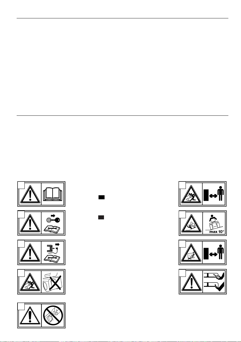
1. Warning: Read the Operator’s Manual before
operating this machine.
2a. Warning: in the electric start models:
remove the key and read the instructions before carrying out any maintenance or repairs.
2b.Warning: in the manual start models: dis-
connect the spark plug cap and read the instructions before carrying out any maintenance or
repairs.
3. Danger! Ejected objects: Do not operate without the grass-catcher in place.
4. Danger! Ejected objects: Keep bystanders
away.
5. Danger! Machine rollover: Do not use this
machine on slopes greater then 10°.
6. Danger! Dismemberment: Make sure that children stay clear of the machine all the time when
engine is running.
7. Danger of cutting yourself. Blade in movement. Do not put hands or feet
near or under the opening of the cutting plate.
8. Warning: do not manipulate the microswitch.
➤
➤
1.3 SAFETY LABELS
Your machine must be used with care. Therefore, labels have been placed on the
machine to remind you pictorially of the main precautions to take during use.
These labels are to be considered an integral part of the machine.
If a label should fall off or become illegible, contact your Retailer to replace it.
Their meaning is explained below.
EN 5SAFETY
before restarting and operating the equipment;
– If the machine starts to vibrate abnormally
(inspect it immediately).
11) Disengage the blade when transporting or
whenever it is not in use.
12) Stop the engine and disengage the blade:
– before refuelling;
– before removing the grass-catcher.
13) Reduce the throttle setting before stopping
the engine.
D) MAINTENANCE AND STORAGE
1) Keep all nuts, bolts and screws tight to be
sure the equipment is in safe working condi-
tion.
2) Never store the machine with petrol in the
tank inside a building where fumes may reach
an open flame or spark.
3) Allow the engine to cool down before storing in any enclosure.
4) To reduce the fire hazard, keep the engine,
silencer, battery compartment and petrol storage area free of grass, leaves, or excessive
grease.
5) Check the grass-catcher frequently for wear
or deterioration.
6) Replace worn or damaged parts for safety.
7) If the fuel tank has to be drained, this
should be done outdoors.
8) When the machine is to be stored or left
unattended, lower the cutting deck.
1
2a
2b
3
8
4
5
6
7
Page 8
2. IDENTIFICATION OF THE MACHINE AND COMPONENTS
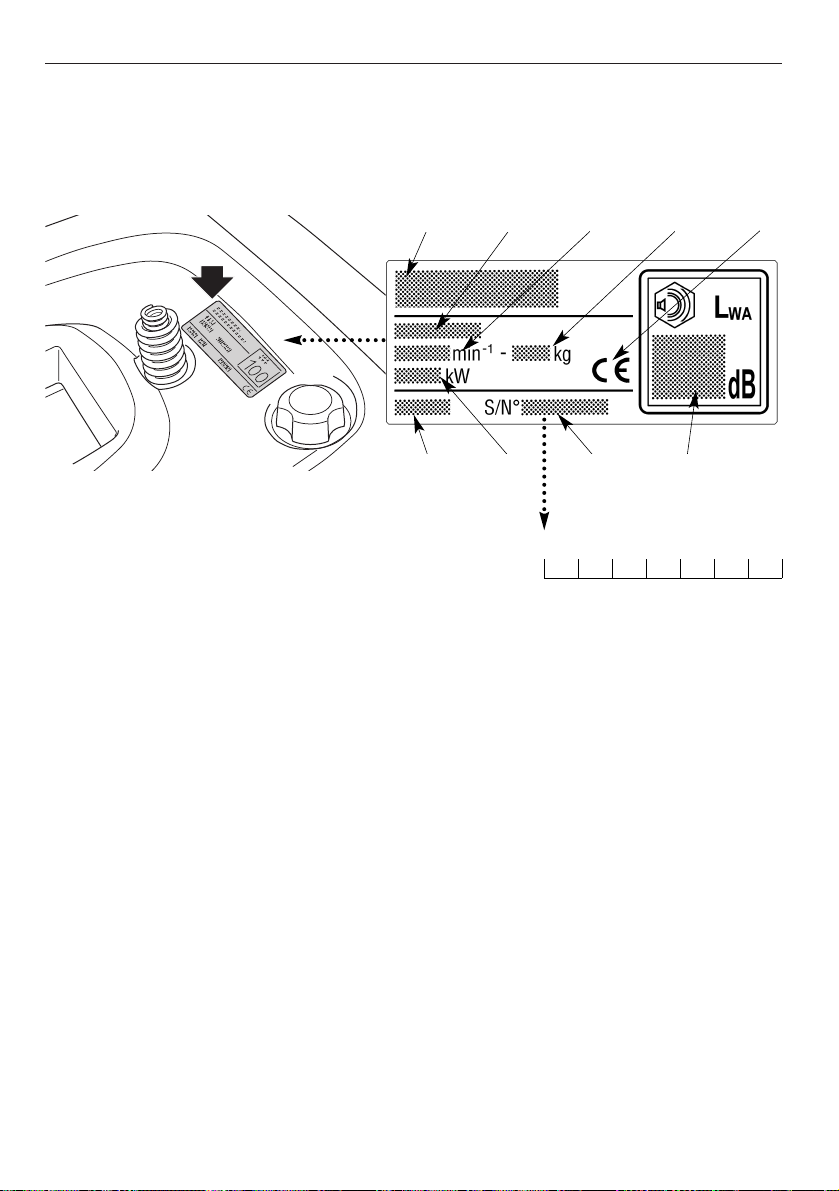
2.1 IDENTIFICATION OF THE MACHINE
The identification label located under the
seat has the essential data of each
machine.
The serial number (7) must be quoted
when you require technical assistance or
spare parts.
1. Acoustic power level according to directive 2000/14/CE
2. Conformity mark according to directive 98/37/EEC
3. Year of manufacture
4. Nominal power (if indicated)
5. Operating engine speed in r.p.m
6. Type of machine
7. Serial number
8. Weight in kg
9. Name and address of Manufacturer
2.2 NAME AND ADDRESS OF MANUFACTURER
The machine is composed of a series of main components that have the following
functions:
11. Cutting deck: this is the guard enclosing the rotating blade.
12. Blade: this is what cuts the grass. The wings at the ends help convey the cut
grass towards the collector channel.
EN 6 IDENTIFICATION OF THE MACHINE AND COMPONENTSI
Write the serial number of your machine
here.
✍
3 4 7 1
69 5 8 2
Page 9
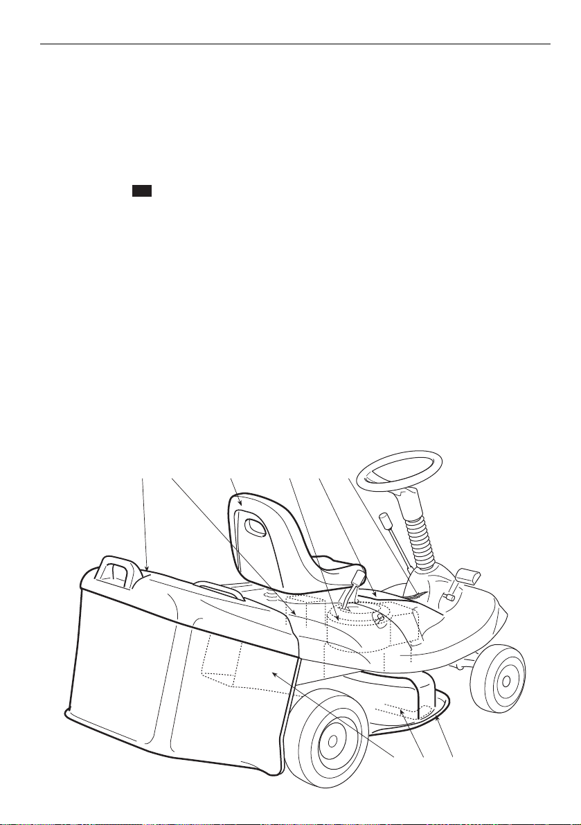
13. Collector channel: this is the part connecting the cutting deck to the grass-
catcher.
14. Grass-catcher: as well as collecting the grass cuttings, this is also a safety
element in that it stops any objects drawn up by the blade from being thrown
outside of the machine.
15. Engine: this moves the blade and drives the wheels. Its specifications and
regulations for use are described in a specific manual.
16. Batteria ( only in the electric start models): provides the energy for
starting the engine. Its specifications and regulations for use are described in
a specific manual.
17. Driver seat: this is where the machine operator sits. It has a sensor which
detects the presence of the operator and acts as a safety device.
18. Labels for regulations and safety: give reminders on the main provisions
for working safely, each of which is explained in chapter 1.
19. Engine cover: for access to the engine
➤
EN 7IDENTIFICATION OF THE MACHINE AND COMPONENTSI
181915171614
111213
Page 10
3. UNPACKING AND ASSEMBLY
The machine is supplied without engine oil or fuel. Before
starting up the engine, fill with oil and fuel following the instructions given in
paragraph 5.3.3. and in the engine manual.
For storage and transport reasons, some components of the machine have to be
assembled after their removal from the packing. Final assembly is carried out by
following these simple instructions.
3.1 UNPACKING
When unpacking the machine, take care to gather all the individual parts, fittings
and documentation.
o avoid damaging the cutting deck when getting the machine
down from the pallet, take it to the maximum height and be very careful.
The supply includes:
– bolts and screws, necessary for completing the assembly
– a syringe for draining the engine oil
In addition ( in the electric start models):
– a battery charger
– 2 starter keys
– a spare 6.3 A fuse, to be kept in case of
necessity.
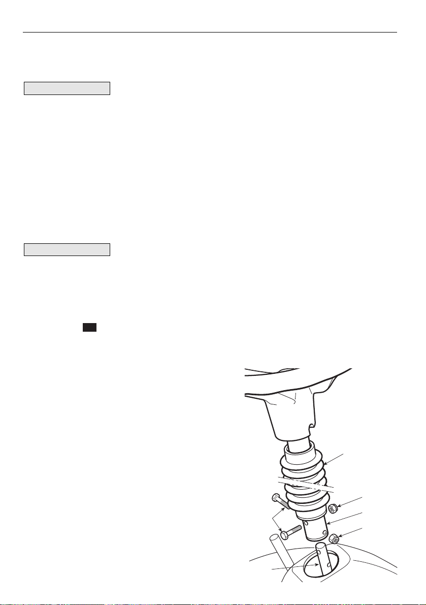
3.2 FITTING THE STEERING WHEEL
Put the machine on a flat surface and straighten up the front wheels.
1. fit the bellows (1) onto the column (2);
2. fit the steering wheel and its column (2)
onto the protruding shaft (3) and fasten it
with the screws (4) and nuts (5) supplied,
using both holes on the shaft (3).
➤
NOTE
IMPORTANT
EN 8 UNPACKING AND ASSEMBLY
1
5
4
3
2
5
Page 11
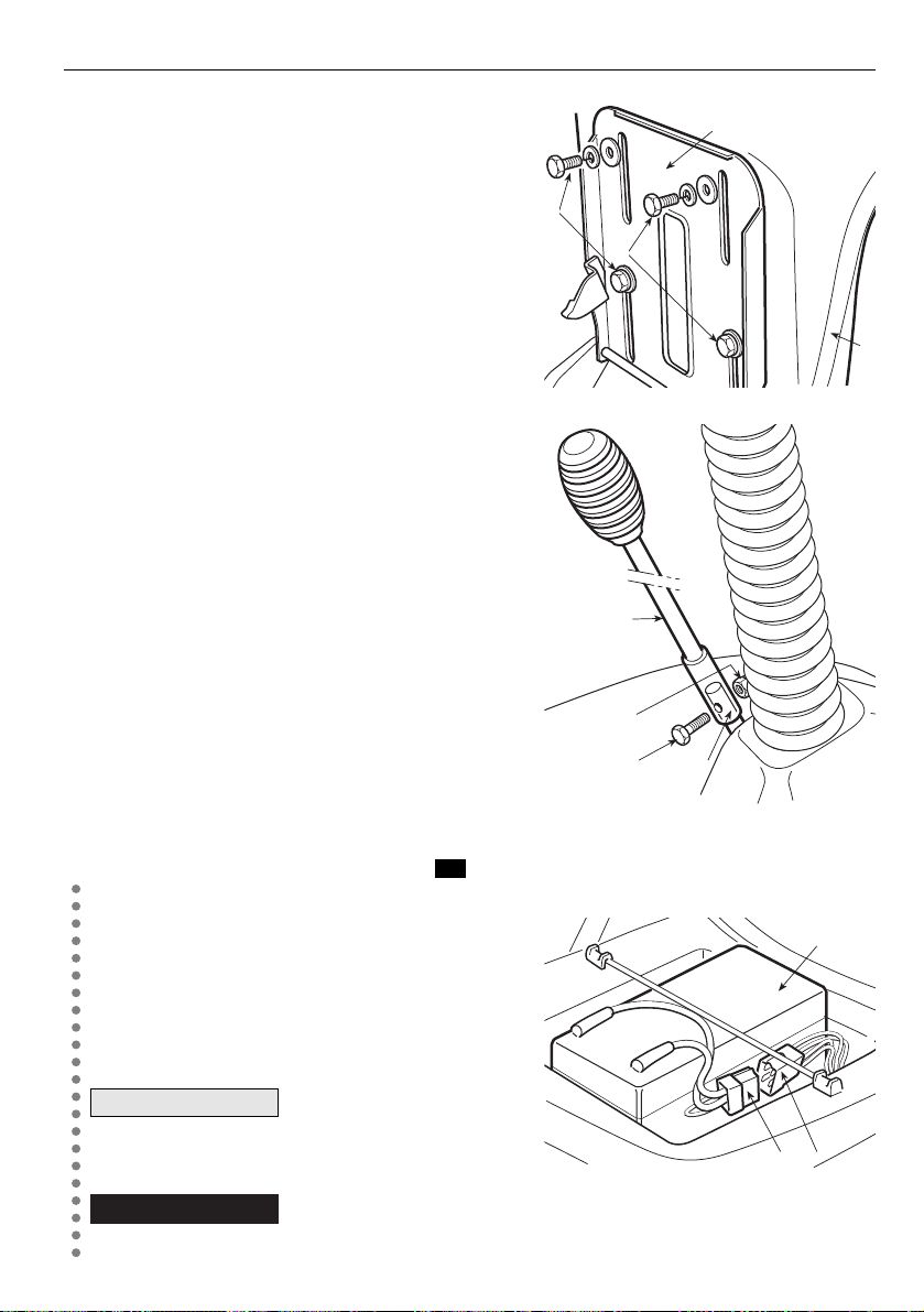
3.3 FITTING THE SEAT
1. Fit the seat (1) onto the plate (2) using the
screws (3).
3.4 FITTING THE BLADE ENGAGEMENT
LEVER
1. Fit the end of the lever (1) on the projecting
part of the pin (2) and fix it all by tightening
the screw (3) and nut (4).
3.5 CONNECTING THE BATTERY ( sonly in the electric start models):
The battery (1) is situated under the seat.
1. Connect the battery connector (2) to the
machine connector (3);
2. recharge the battery by following the
instructions in the manual (☛ 6.2.5).
Never start the engine
until the battery is fully charged!
Follow the battery manufacturer's instructions regard-
ing safe handling and disposal.
!
WARNING!
IMPORTANT
➤
EN 9UNPACKING AND ASSEMBLY
2
3
3
1
1
4
23
1
32
Page 12
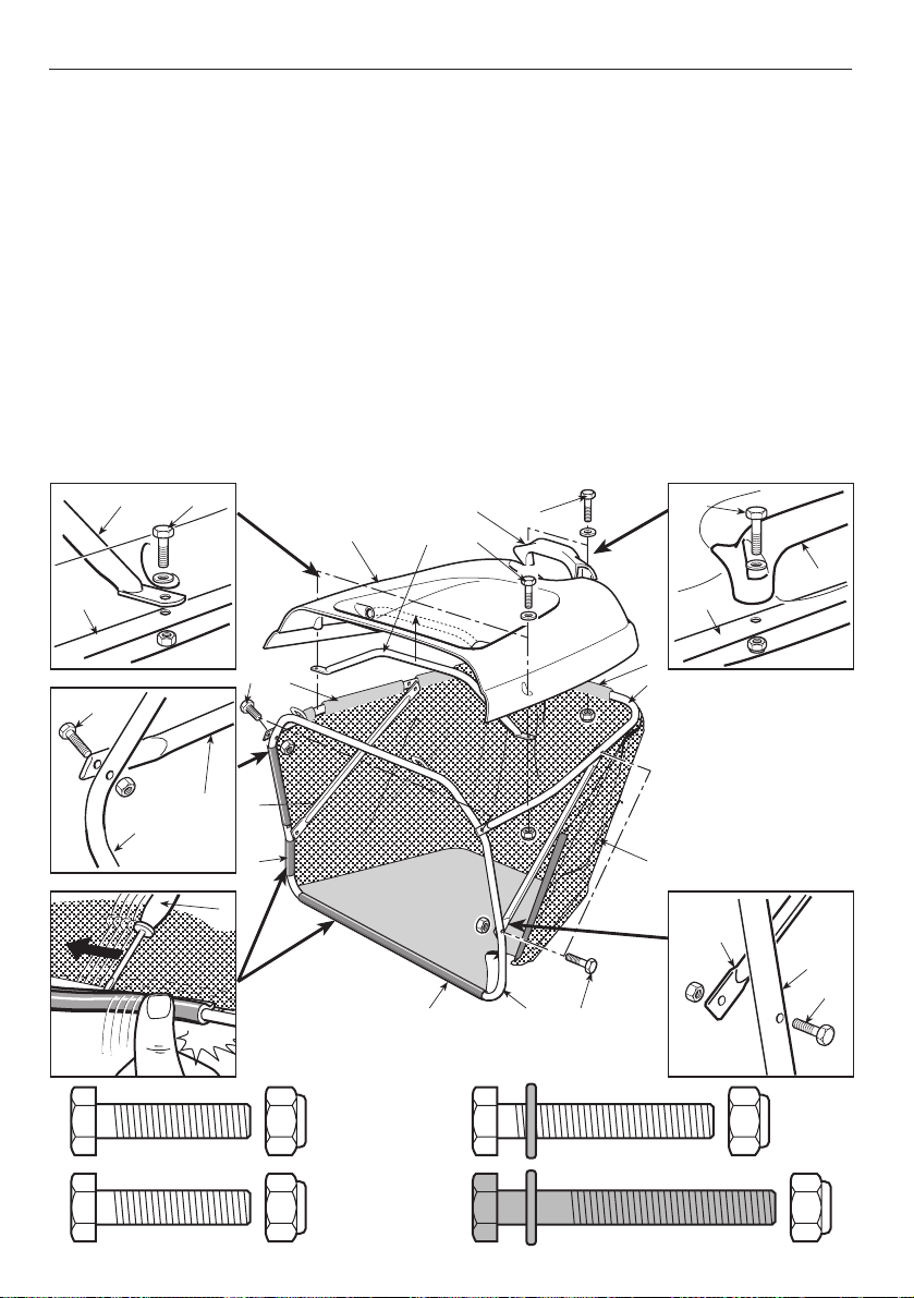
3.6 FITTING THE GRASS-CATCHER
Identify the screws to be used by following the drawing that shows them in their
actual size.
1. Fit the upper frame (1) in the upper slots (2) of the canvas cover (3);
2. join the two pieces of the frame (1) and (4) using the screws (5). Fit the two tie
rods (6) and fasten them by using the screws (7);
3. hook the plastic profiles (8) onto the front frame tubes (4) with the aid of a
screwdriver (9).
4. insert the handle (10) into the holes of the cover (11) and attach this to the
frame using the screws (12);
5. fit the rear handle (13) and fasten it with the screws (14).
EN 10 UNPACKING AND ASSEMBLY
1210
11
1
5
2
5
1
6
4
8
9
K
A
L
C
10
8
13 14
12
7
4
14
13
1
2
1
3
6
4
7
5 (x 2)
7 (x 4)
12 (x 2)
14 (x 2)
Page 13
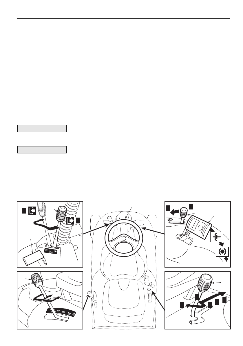
4. CONTROLS AND INSTRUMENTS
4.1. STEERING WHEEL
Turns the front wheels.
4.2 C
LUTCH / BRAKE PEDAL
This pedal has a double function: during the first part of its travel it acts as a
clutch, engaging and disengaging drive to the wheels, and in the second part it
works the brake.
Do not keep the pedal half way of clutch engagement or dis-
engagement, as this can cause overheating and damage the transmission belt.
When the machine is in movement, keep your foot off the
pedal.
4.3 P
ARKING BRAKE LEVER
This lever stops the machine from moving when it has been parked. There are
NOTE
IMPORTANT
EN 11CONTROLS AND INSTRUMENTS
B
4.6.1
4.5
4.6
4.1
A
1
2
3
4
5
B
A
4.3
N
R
4.2
1
4.4
3
2
Page 14

two positions:
«A» = Brake off
«B» = Brake engaged
– The brake is engaged by pressing the pedal (4.3) right down and moving the
lever to position «B». When you take your foot off the pedal it will be blocked by
the lever in the down position.
– To disengage the parking brake, press the pedal (4.3). The lever will return to
position «A».
4.4 S
PEED CHANGE LEVER
This lever has five positions for the three forward gears, the neutral position «N»,
and reverse «R».
– To change gear, press the pedal (4.3) halfway down and move the lever as per
the indications on the label.
Reverse must be engaged when the machine has
stopped.
4.5 C
UTTING HEIGHT ADJUSTING LEVER
There are five positions for this lever, shown as «1» to «5» on the plate, which
correspond to various cutting heights from 3 to 7.5 cm.
– To go from one position to another, move the lever sideways and put it back in
one of the stop notches.
4.6 L
EVER ENGAGEMENT AND BRAKE OF BLADE
The lever has two positions, as shown on the plate:
«A» = Blade disengaged
«B» = Blade engaged
– If the blade is engaged when safety conditions have not been complied with,
the engine shuts down and cannot be restarted (☛ 5.2).
– In disengaging the blade (Pos. «A»), a brake is simultaneously activated which
stops their rotation within a few seconds.
Only for machines with Tecumseh engine:
The blade can only be engaged by pressing the pedal (4.6.1) right down; when
the pedal is released, the lever automatically returns to position «A», disengaging the blade.
➤
!
WARNING!
EN 12 CONTROLS AND INSTRUMENTS
Page 15

In the electric start models
4.11 K
EY IGNITION SWITCH
This key operated control has three
positions:
«OFF» everything is
switched off;
«ON» activates all parts;
«START» engages the
starter motor.
On being released at the «START»
position, the key will automatically
return to «ON».
4.12 A
CCELERATOR LEVEL
Regulates the engine's r.p.m. The positions are indicated on a plate showing
the following symbols:
«CHOKE» starting from cold
«SLOW» for minimum engine speed
«FAST» for maximum engine speed
– The «CHOKE» position enriches the mixture so must only be used for the
time necessary when starting from cold.
– When moving from one area to another, put the lever in a position between
«SLOW» and «FAST».
– When cutting, go to the «FAST» position.
In the manual start models
4.21 P
ULL START HANDLE
To start the engine, take the starter cable handle and give it a firm tug.
➤
➤
EN 13CONTROLS AND INSTRUMENTS
4.11
4.12
Page 16

Then put the handle back in its seat,
guiding the cable as it automatically
rewinds.
4.22 A
CCELERATOR LEVEL
It regulates the rpm and stops the
engine.
The positions are indicated on the
plate showing the following symbols:
«OFF» for switching off the engine
«CHOKE» starting from cold
«SLOW» for minimum engine speed
«FAST» for maximum engine speed
– The «CHOKE» position enriches the mixture so must only be used for the
time necessary when starting from cold.
– When moving from one area to another, put the lever in a position between
«SLOW» and «FAST».
– When cutting, go to the «FAST» position.
EN 14 CONTROLS AND INSTRUMENTS
4.21
4.22
Page 17

EN 15HOW TO USE THE MACHINE
5. HOW TO USE THE MACHINE
5.1 SAFETY RECOMMENDATIONS
The machine must only be used for the purpose for which
it was designed (cutting and collection of grass).
Do not tamper with or remove the safety devices fitted to the machine.
REMEMBER THAT THE USER IS ALWAYS RESPONSIBLE FOR DAMAGE
AND INJURIES TO OTHERS. Before using the machine:
– read the general safety regulations (
☛
1.2), paying particular attention
to driving and cutting on slopes;
– carefully read the instructions for use, become familiar with the controls
and on how to quickly stop the blade and engine.
– never put your hands or feet next to or beneath the rotating parts and
always keep away from the discharge opening.
Do not use the machine when in a precarious state of health or under the
effect of medicines or other substances that can reduce your reflex
actions and your ability to concentrate.
It is the user's responsibility to assess the potential risk of the area where
work is to be carried out, as well as to take all the necessary steps to
ensure his own safety and that of others, particularly on slopes or rough,
slippery and unstable ground.
Do not leave the machine stopped on high grass with the engine running
to avoid the risk of starting a fire.
Always lower the speed when changing direction, especially on tight
turns.
This machine must not be used on slopes greater than
10° (17%) (
☛
5.5).
All the references relating to the positions of controls are
those described in chapter 4.
5.2 WHY THE SAFETY DEVICES CUT IN
The safety devices work in two ways:
– by preventing the engine from starting if all the safety requirements have not
been met;
– by stopping the engine if even just one of the safety requirements is lacking.
IMPORTANT
!
WARNING!
!
DANGER!
Page 18

a) The engine must only be started in the following conditions:
– the transmission is in “neutral”;
– the blade is not engaged;
– the operator is seated or the parking brake is engaged. ( Only for
machines with B&S engine)
b) The engine stops when:
– the operator leaves his seat when the blade is engaged;
– the operator leaves his seat with a gear engaged;
– the grass-catcher is lifted without disengaging the blade;
– the blade is engaged without the grass-catcher in place;
– the parking brake is engaged without disengaging the blade. ( Only for
machines with B&S engine)
5.3 PRELIMINARY OPERATIONS BEFORE STARTING WORK
These controls ensure that the work gives the best results and is done in maximum safety.
5.3.1 S
EAT ADJUSTMENT
Adjust the seat by sliding it along the bracket
slots.
1. Loosen the four screws (1);
2. once you have found the right position, securely tighten the four screws (1).
5.3.2 T
YRE PRESSURE
Having the correct tyre pressure is essential for ensuring that the cutting deck is
perfectly horizontal and thus mows evenly.
1. Unscrew the valve caps;
2. connect a compressed air line with a gauge
to the valves and check that the pressure is:
– Front tyres 1.8 bar
– Rear tyres 1.3 bar
3. screw the valve caps back on.
➤
➤
EN 16 HOW TO USE THE MACHINE
1
1
Page 19

EN 17HOW TO USE THE MACHINE
5.3.3 FILLING WITH OIL AND FUEL
Refuelling should be carried out in an open or well-ventilated area with engine stopped. Always remember that petrol fumes are
inflammable. DO NOT TAKE A NAKED FLAME TO THE TANK’S OPENING IN
ORDER TO SEE THE TANK’S CONTENTS AND DO NOT SMOKE WHEN
REFUELLING.
The type of oil and fuel to be used is given in the engine man-
ual.
With the engine stopped, check its oil level.
1. to reach the plug (1), remove the engine
cover (2) with the aid of a screwdriver;
2. by closely following the methods described in the engine manual, make sure
the oil level is between the MIN and MAX
marks on the dipstick (3);
3. always refit the plug (1) and engine cover
(2).
To refuel (to be done when the machine has
stopped):
1. unscrew the plug (4) from the tank located
behind the seat;
2. refuel using a funnel, but do not completely
fill the tank. The tank's capacity is about
3.5 litres;
3. always refit the plug (4).
Do not drip petrol onto the plastic parts to avoid ruining them.
In the event of accidental leaks, rinse immediately with water.
IMPORTANT
NOTE
!
DANGER!
2
1
3
MAX
MIN
4
Page 20

5.3.4 FITTING THE PROTECTIONS AT THE EXIT
(GRASS CATCHER)
Never use the machine
without having fitted the exit protection!
Hook the grass-catcher (1) onto the brackets
(2) and centre it up with the rear plate, so that
the two reference marks (3) coincide.
5.3.5 C
HECKING THE EFFECTIVENESS OF THE SAFETY DEVICES
Check that the safety systems are working properly by simulating the various situations of usage (☛ 5.2) and by making sure that the correct result is achieved for
each situation.
If the check shows any deficiencies, consult a Licensed Service Centre immediately.
5.3.6 C
HECKING THE BRAKING SYSTEM
Make sure that the machine’s braking capacity is adequate for the conditions of
usage. Avoid starting the machine if you have doubts on the brake efficiency.
If necessary, adjust the brake (☛ 6.3.4) and if you still have doubts on its efficiency, consult a Licensed Service Centre
5.3.7 C
HECKING THE BLADE
Wear strong gloves when handling the blade.
Check that the blade is sharpened properly and firmly fixed to the bracket.
– A badly sharpened blade pulls at the grass and causes the lawn to turn yellow.
– A loose blade causes unusual vibrations and can be dangerous.
If the check shows any problems, sharpen or fasten the blade properly (☛ 6.3.1).
!
WARNING!
!
WARNING!
EN 18 HOW TO USE THE MACHINE
1
2
3
Page 21

EN 19HOW TO USE THE MACHINE
5.4 USING THE MACHINE
5.4.1 S
TARTING THE ENGINE
All starting operations have to be effected in an open or
well-ventilated area! ALWAYS REMEMBER THAT EXHAUST GASES ARE
TOXIC!
To start the engine:
1. sit on the seat and press the brake pedal right down (☛ 4.3);
2. put the transmission into neutral («N») (☛ 4.4);
3. disengage the blade (☛ 4.6);
4. when starting from cold, put the accelerator lever in the «CHOKE» position
shown on the label (☛ 4.12 - 4.22). Alternatively, if the engine is still hot, position the lever between «SLOW» and «FAST»;
In the electric start models
5. put in the key (☛ 4.11) and turn to «ON» to make electrical contact, then
turn to «START» to start the engine;
6. release the key once the engine has started;
In the manual start models
5. take the starter cable handle (☛ 4.21) and firmly
tug it.
6. once the engine has started, put the handle back
in its seat.
7. After the machine has run for a few seconds, put the accelerator lever on
«START» and then on «SLOW».
he choke must be closed as soon as possible. Using it when
the engine is already warm can foul the spark plugs and cause the engine to
run erratically.
If you have difficulty starting, do not make several attempts to
avoid flooding the engine or running down the battery (if present).
– Check that the conditions allowing the engine to start are met
– Turn the key ( electric start) or the accelerator ( manual start) to
«OFF». Wait for a few seconds and repeat the start operation. Should the
➤➤
NOTE
IMPORTANT
➤
➤
!
DANGER!
Page 22

malfunction persist, refer to chapter «7» of this manual and the engine manual.
5.4.2 S
TARTING AND MOVING WITHOUT MOWING
This machine has not been approved for use on public
roads. It has to be used (as indicated by the highway code) in private
areas closed to traffic.
When moving the machine, the blade must be disengaged
and the cutting deck put at its highest position (position «5»).
To start the forward movement:
1. put the accelerator control between the «SLOW» and «FAST» positions;
2. push the pedal right down (☛ 4.2) and put the gear change lever in 1st gear
(☛ 4.4).
3. release the pedal gradually to begin the movement.
Reach the desired operating speed using the accelerator and gear lever. To
change gear, the clutch must always be used by pushing the pedal (☛ 4.2).
The pedal must be released gradually as sudden en-
gagement may cause tipping up and loss of control of the vehicle.
5.4.3 B
RAKING
To brake:
1. first slow down the machine by reducing the engine speed;
2. push the pedal right down (☛ 4.2) to lower the speed even more until the
machine stops.
5.4.4 R
EVERSE
Reverse MUST be engaged only when the machine has stopped.
The reverse is engaged in the same way as above (☛ 5.4.2), by moving the lever
sideways and putting it into position «R».
!
WARNING!
NOTe
!
WARNING!
EN 20 HOW TO USE THE MACHINE
Page 23

EN 21HOW TO USE THE MACHINE
5.4.5 GRASS CUTTING
The machine is not designed for heavy-duty use or for mow-
ing large quantities of grass.
The blade is engaged by means of a clutch device. To avoid
damage or premature wear of the friction elements, strictly observe the following instructions.
To start cutting:
1. remove any foreign objects that could be hit by the blade (stones,
branches, bones, wire etc.) and mark off the position of hidden
elements that cannot be moved (roots, sprinklers etc.);
2. check that the grass-catcher is fitted properly;
3. put the accelerator lever into the «FAST» position;
4. bring the cutting deck to the highest position before engaging the
blade;
5. engage the blade (☛ 4.6) without remaining in the midway positions, whilst staying away from high grass;
6. start moving forwards onto the grass area very gradually and with particular
caution, as already described;
7. on rough ground, adjust the cutting height to prevent the blade from knocking
against uneven ground or foreign objects, damaging the blade and bracket;
8. engage the most suitable gear in order to reach the desired forward speed (1st
- 2nd gear) and adjust the cutting height (☛ 4.5) so that the quantity of grass
to be removed is not too much that it jams the blade or clogs up the collector
channel.
When cutting on sloping ground, the forward speed
!
WARNING!
IMPORTANT
IMPORTANT
Page 24

must be reduced to ensure safe conditions ( ☛ 1.2 - 5.5).
– Lower the speed whenever you note a reduction in engine speed, since a for-
ward speed that is too fast compared to the amount of grass being cut will
never mow the grass well.
– Disengage the blade and put the cutting deck in the highest position whenever
you need to get past an obstacle or a hump.
– Use the 3rd gear only when moving the machine from one area to the other.
5.4.6 E
MPTYING THE GRASS-CATCHER
The grass-catcher is full when the grass cuttings remain on the lawn. If you continue mowing with the grass-catcher full, it may block the collector channel.
To empty the grass-catcher:
1. lower the engine speed;
2. go into neutral (N) (☛ 4.4) and stop the
machine’s forward movement;
3. disengage the blade (☛ 4.6);
4. engage the parking brake on slopes;
5. hold onto the rear handle and tip up the
grass-catcher to empty it;
This operation can only be
done with the blade disengaged, otherwise
the engine stops.
5.4.7 U
NBLOCKING THE COLLECTOR CHANNEL
This job must only be performed with the engine turned
off.
If the collector channel gets blocked (due to accumulated grass cuttings filling up
the grass-catcher or an excessively high speed with relation to the quantity of
grass cuttings), you need to:
1. stop forward movement immediately, disengage the blade and stop the engine;
2. remove the grass-catcher;
3. rremove the accumulated cuttings, reaching them from the exit of the collector
channel.
!
WARNING!
NOTE
EN 22 HOW TO USE THE MACHINE
Page 25

EN 23HOW TO USE THE MACHINE
5.4.8 END OF MOWING
When you have finished mowing, disengage the blade, lower the engine speed
and ride the machine with the cutting deck in the highest position.
5.4.9 E
ND OF WORK
Once you have finished mowing, stop the machine and engage the parking brake.
In the electric start models:
1. shift the accelerator lever to «SLOW»;
2. switch off the engine by turning the key to «STOP»:
Always take out the ignition key before leaving the
machine unattended!
To keep the battery charged, do not leave the key in the
«ON» position when the engine is not running.
In the manual start models:
1. shift the accelerator lever to «OFF».
Always make sure that the accelerator level is in the
«OFF» position before leaving the machine unattended!
5.4.10 C
LEANING AND STORAGE
Always empty the grass-catcher and do not leave con-
tainers full of cut grass inside a room.
After each mowing, clean the outside of the machine, empty the grass-catcher
and shake it to remove residual grass and earth.
Clean the plastic parts of the body with a damp sponge using water and detergent, taking care not to wet the engine, the electrical parts or the electronic card.
Never use hose nozzles or harsh detergents for cleaning the
body and engine!
For washing the inside of the cutting deck and the collector channel the machine
IMPORTANT
!
WARNING!
!
WARNING!
➤
IMPORTANT
!
WARNING!
➤
Page 26

must be on firm ground:
1. fit the grass-catcher;
2. connect a water hose to its pipe fitting (1), and
run water through it;
3. sit at the operator’s position;
4. lower the cutting deck completely;
5. start the engine and stay in neutral;
6. engage the blade and leave it to turn for a few
minutes.
Take off the grass-catcher, empty and rinse it, then put it in a position where it can
dry quickly.
Put the machine away in a dry place protected from the weather and, if possible,
cover it with a cloth.
5.4.11 I
NACTIVITY FOR LONG PERIODS
Carefully remove any dry grass cuttings which may have
collected around the engine or silencer to prevent their catching fire the
next time the machine is used!
If the machine is likely to be unused for a long period (more than 1 month), follow
the instructions in the engine manual. Lubricate all joints as indicated (☛ 6.2.1).
In the electric start models:
Disconnect the connectors (2 and 3) of the
battery (1).
The battery must be kept
in a cool and dry place. Before a long storage period (more than 1 month), always
charge the battery, and then recharge
before using again (
☛
6.2.5).
Empty the fuel tank by disconnecting the tube situated at the inlet of the fuel filter
IMPORTANT
➤
!
WARNING!
EN 24 HOW TO USE THE MACHINE
1
1
32
Page 27

(1) and reached by the right-hand side above
the collector channel. Then remember to reconnect the tube.
The next time the machine is used, check that
there are no fuel leaks from the tubes or carburettor.
5.5 USING ON SLOPES
When mowing lawns on a slope, observe
the maximum gradients already mentioned (max 10° - 17%) and move up and
down but never across them. Take great
care when changing direction that the
highest wheels do not hit obstacles (such
as stones, branches, roots, etc.) that may
cause the machine to slide sideways, tip
over or otherwise cause loss of control.
SLOW DOWN BEFORE CHANGING DIRECTION ON
SLOPES. Never use reverse to reduce speed going downhill: you may
lose control of the machine, particularly on slippery surfaces. Never ride
the machine on slopes in neutral or with the clutch out! Always engage a
low gear and the parking brake before leaving the machine at a stopped
and unattended.
Take care when beginning forward movement on sloping
ground to prevent the risk of tipping up.
Reduce the forward speed before going on a slope, particularly downhill.
5.6 TRANSPORTING
If the machine is transported on a truck or trailer, use
suitable equipment for lifting and an appropriate number of people for the
weight involved and the type of lifting system used. The machine must
!
WARNING!
!
WARNING!
!
DANGER!
EN 25HOW TO USE THE MACHINE
RIGHT!
WRONG!
1
max 10° (17%)
Page 28

never be lifted by rope and tackle. During transport, lower the cutting
deck, engage the parking brake and fasten the machine securely to the
hauling device with ropes or chains.
5.7 ADVICE ON HOW TO OBTAIN A GOOD CUT
1. To keep a lawn green and soft with a good appearance, it should be cut regu-
larly without damaging the grass.
2. It is always better to cut the grass when dry.
3. The blade must be in good condition and well sharpened so that the grass is
cut straight without any ragged edge that leads to yellowing at the ends.
4. The engine must run at full speed, both to ensure a sharp cut of the grass and
to get the necessary thrust to push the cuttings through the collector channel.
5. The frequency of mowing should be in relation to the rate of growth of the
grass, which should not be left to grow too much between one cut and the next.
6. During hot and dry periods, the grass should be cut a little higher to prevent
the ground from drying out.
7. If the grass is very tall, it should be cut twice in
a twenty-four hour period. The first time at maximum cutting height, possibly reducing the cutting
width and the second cut at the height desired.
8. The appearance of the lawn will improve if you
alternate the cutting in both directions.
9. If the collector channel tends to get blocked with grass, you should reduce the
forward speed since this may be too high for the condition of the lawn. If the problem persists, the probable causes are either the badly sharpened blade or deformed wings.
10. Be very careful when mowing near bushes or kerbs since these could distort
the horizontal position of the cutting deck, and damage its edge as well as the
blade.
EN 26 HOW TO USE THE MACHINE
2
1
Page 29

EN 27MAINTENANCE
6. MAINTENANCE
6.1 SAFETY RECOMMENDATIONS
Disconnect the spark plug cap, remove the key ( in
the electric start models) or shift the accelerator lever to «OFF» ( in
the manual start models) and read the relevant instructions before starting any cleaning, maintenance or repairs. Wear suitable clothing and
strong gloves for dismantling and refitting the blade and in all other hazardous situations for the hands.
Never use the machine with worn or damaged parts.
Faulty or worn-out parts must always be replaced and not repaired. Only
use genuine spare parts: those that are not of an equivalent quality may
damage the machine or endanger the safety of yourself and others.
Never get rid of used oil, fuel or other pollutants in unauthorised places!
6.1.1 L
IFTING THE LIFT VERTICALLY
In order to have easy access to the lower part of the machine, you can lift it vertically.
Place the machine on
firm and flat ground. At least two competent people should be involved in this
operation to assure the necessary safety.
1. Empty the fuel tank;
2. bring the cutting deck to position «5»;
3. insert a block (1) about 60 mm long
underneath the rear plate, taking care to position it between the edge of the
plate and the exit of the collector channel;
4. lift the machine from the front, holding onto parts that offer a firm grip (apart
from the steering wheel) and rest it on the points shown, taking care not to
damage the grass-catcher’s brackets.
Be sure of the good stability of the machine before car-
!
DANGER!
!
WARNING!
IMPORTANT
!
WARNING!
➤
➤
!
WARNING!
60 mm
1
Page 30

rying out any type of work on it and avoid operations which may cause it
to fall over.
6.2 ROUTINE MAINTENANCE
6.2.1 M
AINTENANCE AND GENERAL LUBRICATION
Follow the diagram showing the points requiring checks, lubrication and routine
maintenance, together with the type of lubricant to be used and the frequency
required.
EN 28 MAINTENANCE
25 HOURS 25 HOURS
OIL - SAE 30
Page 31

EN 29MAINTENANCE
6.2.3 ENGINE
Follow all the instructions in the engine manual.
To drain the engine oil:
1. unscrew the topping up cap (1);
2. fit the pipe (2) onto the syringe (3) and
insert it right into the hole;
3. using the syringe (3), suck up all the engine oil, bearing in mind that you need to
repeat this operation a few times before
all the oil is removed.
6.2.4 G
EAR LEVER AND DIFFERENTIAL
These are sealed single units which do not require maintenance. They are permanently lubricated and this lubricant does not need changing or topping up.
6.2.5 B
ATTERY ( Only in the electric start models)
To ensure long life to the battery it is essential to keep it carefully maintained.
The machine battery must always be charged:
– before using the machine for the first time after purchase;
– before leaving the machine for a prolonged period of disuse;
– before starting up the machine after a prolonged period of disuse.
– To ensure long life to the battery it is essential to keep it carefully main-
tained. Failure in following the procedure or in charging the battery could
permanently damage the battery elements.
– A flat battery must be recharged as soon as possible.
Recharging must be done using a battery charger at con-
stant voltage. Other recharging systems can irreversibly damage the battery.
The machine has a connector (1) for recharging located next to the battery,
IMPORTANT
➤
3
1
2
Page 32

which is to be connected to the corresponding connector of the special “CB02”
maintenance battery charger supplied.
This connector must
only be used for connecting to the
“CB02” maintenance battery charger. For
its use:
– follow the instructions given in the rela-
tive instructions manual;
– follow the instructions given in the bat-
tery manual.
6.3 CHECKS AND ADJUSTMENTS
6.3.1 D
ISMANTLING, SHARPENING AND BALANCING THE BLADE
A badly sharpened blade tears at the grass, reduces collection and makes the
lawn turn yellow. To dismantle the blade, hold onto it tightly using work gloves and
loosen the two screws (1).
Sharpen the two cutting edges using a medium grade grinding wheel and check the balance by holding the blade up with a round 18
mm Ø bar inserted in the central hole.
Always replace the
damaged or bent blade; never try to
repair it! ALWAYS USE MANUFACTURER'S GENUINE REPLACEMENT
BLADES BEARING THE SYMBOL !
When assembling,
screw down the fixing bolts (1). If
necessary, replace the nuts and bolts
only with GENUINE SPARE PARTS.
!
WARNING!
!
WARNING!
IMPORTANT
EN 30 MAINTENANCE
1
1
Ø 18 mm
Page 33

EN 31MAINTENANCE
6.3.2 CUTTING DECK ALIGNMENT
The cutting deck should be properly set to obtain a good cut.
To achieve good results from cutting, the front part should
always be 5 - 6 mm lower than the rear.
1. Put the machine onto a flat surface and
check the tyre pressure;
2. put 26 mm blocks (1) under the front edge
of the deck and 32 mm blocks (2) under
the rear edge, then put the lifting lever into
position «1»;
3. loosen the nuts (3-5), the locknuts (4-6) on
the right and left-hand side and the nuts (7
– 8), so that the deck is resting firmly on
the blocks;
4. tighten the nut (3) and the locknut (4);
5. turn the nut (7) until the front part of the
deck just begins to rise;
6. turn the nut (5) until the rear part of the
deck just begins to rise and tighten the
locknut (6);
7. check the front part and if necessary, turn
the nut (7);
8. tighten the nut (8) on the pin (9).
If you are unable to adjust the cutting deck
properly, consult a Licensed Service Centre.
6.3.3 A
DJUSTING THE ENGAGEMENT AND BRAKE OF THE BLADE
When you operate the lever to disengage the blade, this also brings the brake into
operation for stopping the blade within few seconds.
If this is faulty, contact a Licensed Service Centre.
NOTE
2
1
3
4
7 859
6
Page 34

6.3.4 BRAKE ADJUSTMENT
If the braking distance lengthens, the
brake will need adjusting.
The adjustment will need to be made with
the parking brake ENGAGED.
1. Remove the collector channel (1),
which is fixed by a pin (2) and split pin
(3);
2. turn the adjusting nut (4) (which is
reached by taking off the engine cover)
until there is a distance of 86-88 mm
between the bracket (5) and the upper
part of the lever (6).
3. refit the collector channel (1) and put
the pin (2) and split pin (3) back in
place.
If the brake still does not work properly even after this
adjustment, immediately contact the Licensed Service Centre. DO NOT
ATTEMPT ANY OTHER WORK ON THE BRAKE THAN WHAT IS
DESCRIBED HERE.
6.3.5 A
DJUSTING THE TENSION OF THE DRIVE BELT
If you should notice that forward drive power has
dropped, it will be necessary to adjust the spring
of the stretcher. Make the adjustment with the
parking brake DISENGAGED (to make sure that
the machine does not move) and with the cutting deck in position «3».
1. Remove the collector channel (1), fastened
by a pin (2) and the split pin (3);
2. check that the cap (4) of the engagement
cable is fitted firmly in its correct position;
3. turn the nuts (5) until the spring (6) reaches a
total length of 174 - 176 mm measured from
the outer ends of the eyelets;
!
WARNING!
EN 32 MAINTENANCE
86 - 88 mm
174 - 176
mm
3
1
2
6
5
3
2
4
1
5
6
4
Page 35

EN 33MAINTENANCE
4. check that the spring (7) of the engagement
cable is not too taut or too loose. Otherwise, turn the adjusting nut (8) until the
spring reaches the right condition.
5. check the measurement of the spring (6)
again;
6. refit the collector channel (1), and always
put back the pin (2) and the split pin (3).
6.4 DISMANTLING AND REPLACEMENT
6.4.1 R
EPLACING WHEELS
1. Place the machine on a flat surface and
put blocks under a load-bearing part of
the frame on the side of the wheel to be
changed;
2. using a screwdriver, remove the snap ring
(1) and the washer (2);
3. pull out the wheel.
Smear some waterproof
grease on the axle and after refitting the
wheel, carefully refit the washer (2) and the snap ring (1).
Should you replace wheels or tyres, ensure that the right and
left wheels are of the same rolling diameter, and check that cutting deck is adjusted properly to prevent an uneven cut.
6.4.2 R
EPLACING AND REPAIRING TYRES
All puncture repairs or replacements will have to be carried out by a tyre repair
expert in accordance with the methods for the kind of tyre used.
NOTE
IMPORTANT
87
1
2
Page 36

6.4.3 ELECTRIC AND PROTECTION SYSTEM
In the electric start models:
The electric system and the electronic card
are protected by a fuse. When it blows the
machine stops, so in this case:
1. tighten the two screws (1) that fasten the
box (2) containing the card, and hold up
the lower part to prevent it from falling;
2. remove the lid (3) and pull out the card
(4) slightly;
3. replace the fuse (5) with another one of
6.3 A (delayed).
4. always put the lid (3) back on and refit
the box (2) in its correct position.
A blown fuse must
always be replaced by one of the same type and ampere rating, and never
with one of another rating.
If you cannot find out why the fuse has blown, consult a Licensed Service
Centre.
In the manual start models:
The electric system and the card are not protected by any fuses. If the safety
system fails to work properly or there are engine problems due to the electric
system, contact a Licensed Service Centre.
6.4.4 R
EPLACING THE BELT
The belt replacement must be carried out at a Licensed Service Centre.
Replace the belts as soon as they show obvious signs of
wear! ALWAYS USE GENUINE REPLACEMENT BELTS!
NOTE
➤
IMPORTANT
➤
EN 34 MAINTENANCE
)
1
2
3
4
(6.3 Amp
Page 37

EN 35TROUBLESHOOTING
7. TROUBLESHOOTING
PROBLEM LIKELY CAUSE SOLUTION
1. With the key
on «START» the
starter motor
does not run
2. With the key on
«START» the
starter motor runs
but the engine
does not start
3. The engine
stops
Electronic card blocked due to:
– flat battery or sulphated battery plates
– fuse blown
– bad earthing to the engine or the frame
– earth connections of the microswitches
disconnected
– badly earthed starter motor
– you are not ready for starting
– faulty fuel supply
– faulty ignition
Electronic card blocked due to:
– earth connections of the microswitches
disconnected
– flat battery
– badly connected battery (poor contact)
– engine badly earthed
Turn the key to «STOP» and look for the
cause of the problem:
– recharge battery (☛ 6.2.5)
– replace fuse (6.3 A - delayed)
(☛ 6.4.3)
– check connections of black earth leads
– check connections
– check earth connections
– check that the conditions allowing the
start are met (☛ 5.2.a)
– check the level in the tank
(☛ 5.3.3)
– check the wiring of the fuel open com-
mand
– check fuel filter
– check that spark plug caps are firmly
fitted
– check that the electrodes are clean
and have the correct gap
Turn the key to pos. «OFF» and look for
the cause of the problem:
– check connections
– recharge battery (☛ 6.2.5)
– check connections (☛ 3.5)
– check engine earth connection
in the electric start models
➤
Page 38

PROBLEM LIKELY CAUSE SOLUTION
EN 36 TROUBLESHOOTING
4. The engine
does not start
5. The engine
stops
6. Starting is difficult
or the engine runs
erratically
7. Weak engine performance during cutting
8. Engine stops when
blade is engaged
– earth connections of the microswitches
disconnected
– you are not ready for starting
– faulty fuel supply
– faulty ignition
– earth connections of the microswitches
disconnected
– fault in carburation
– forward speed too high in relation to
cutting height
– you are not ready to engage the blade
– check connections
– check that the conditions allowing the
start are met (☛ 5.2.a)
– check the level in the tank (☛ 5.3.3)
– check the wiring of the fuel open com-
mand
– check the fuel filter
– check that spark plug caps are firmly
fitted
– check that the electrodes are clean and
have the correct gap
– check connections
– clean or replace the air filter
– flush out the float chamber
– empty fuel tank and refill with fresh
fuel
– check and, if necessary, replace fuel
filter
– reduce the forward speed and/or raise
the cutting deck (☛ 5.4.5)
– check that the safety requirements are
met (☛ 5.2.b)
in the manual start models
➤
Page 39

EN 37TROUBLESHOOTING
PROBLEM LIKELY CAUSE SOLUTION
– check the tyre pressure (☛ 5.3.2)
– realign the cutting deck to the ground
(☛ 6.3.2)
– check that the blade is fitted properly
(☛ 6.3.1)
– sharpen or fit new blade (☛ 6.3.1)
– reduce forward speed and/or raise the
cutting deck (☛ 5.4.5)
– wait for the grass to dry
– remove the grass-catcher and empty
the collector channel (☛ 5.4.7)
– clean the cutting deck (☛ 5.4.10)
– balance or replace the blade if dam-
aged (☛ 6.3.1)
– check that the blade is fastened prop-
erly (☛ 6.3.1)
– check and tighten all the fixing bolts of
the engine and frame
– cutting deck not parallel to the ground
– blade cutting badly
– forward speed too high compared to
height of grass
– collector channel is blocked
– cutting deck full of grass
– blade unbalanced
– blade loose
– fixing bolts loose
9. Uneven cut and
poor grass collection
10. Unusual vibrations
while working
If problems continue after having carried out these operations, contact a
Licensed Service Centre.
Do not take on complicated repair work if you don't
have the necessary equipment and the technical knowledge. The guarantee is automatically revoked and the manufacturer declines all
responsibility for any bad repairs.
!
WARNING!
Page 40

EN 38 ACCESSORIES ON REQUEST
8. ACCESSORIES ON REQUEST
1. KIT FOR “MULCHING”
It finely chops the grass cuttings and leaves them
on the lawn, instead of collecting them in the grasscatcher.
1
Page 41

EN 39SPECIFICATIONS
9. SPECIFICATIONS
Electrical system ( Only in the electric start models)................................ 12 V
Battery ( Only in the electric start models) ............................................ 7,2 Ah
Front tyres ...........................................................................................11 x 4.00-4
Rear tyres ........................................................................................... 13 x 5.00-6
Front tyre pressure .................................................................................... 1.8 bar
Rear tyre pressure ..................................................................................... 1.3 bar
Overall weight ......................................................................... from 106 to 115 kg
Forward speed (approximate) at 3000 min
-1
:
in 1st ................................................................................................... 2.5 km/h
in 2nd ................................................................................................. 4.0 km/h
in 3rd .................................................................................................. 8.0 km/h
in Reverse ........................................................................................... 3.5 km/h
Inside turning circle (minimum diameter of uncut grass) .............................. 1.5 m
Cutting height ..................................................................................... 3 ÷ 7.5 cm
Cutting height .............................................................................................. 62 cm
Grass-catcher capacity ......................................................................... 140 litres
➤
➤
1028 ÷ 1054
960
1310
1805
670
720
703
Page 42

★★★★★
EMAK s.p.a. - Member of the YAMA group
42011 BAGNOLO IN PIANO (REGGIO EMILIA) ITALY
TEL. 0522 956611 - TELEFAX 0522 951555
EMAIL service@emak.it - INTERNET http://www.emak.it
Realizzazione: EDIPROM / bergamo - PRINTED IN ITALY
 Loading...