

Page 1
EF 92S/13H
EF 92S/16H
OM 92S/13H
OM 92S/16H
Blizzard 92/13H
GB
User‘s manual
D
Bedienungsanleitung
IT
Manuale di istruzioni
F
Manuel d’utilisation
PL
Instrukcja obsługi
ES
Manual de usuario
NL
Gebruikershandleiding
Page 2
8
1.2
1
2
9
7
6
5
4
3
1.3.1
1.3.2a
TYPE N°: AJ-92
1
ENGINE: 6,76kW - 2700 min-1
2
YEAR OF PRODUCTION: XXX
3
WEIGHT: 216kg
4
FABRICATION: Seco GROUP a.s., BRANCH PLANT 02
5
6
CE CONFORMITY: 2006/42/EC;2004/108/EC
Jicin , Jungmannova 11
Czech Republic
2000/14/EC;2002/88/EC
8
L
9
MADE IN EUROPE
7
100dB
2
Page 3
1.3.2b
1.3.2c
MAX
10
o
1.3.2d
1.3.2e
R
N
F
3
Page 4
3.1
3.3.1a
3.3.1b
4
Page 5
3.3.1c
3.3.1d
5
Page 6
8
9
10
11
3.3.2a
3.3.2b
1
2
3
4
7
2
4
6
6
5
1
4
3.3.2c
3
10
12
8
7
9
6
5
Page 7
3.3.2d
M54xx 16
M5
3.3.2e
3.3.2f
2x
M5 x 16
M5
M5 x 30
4x
M5
7
Page 8
3.3.2g
3.3.2h
2x
M5 x 35
M5
8
Page 9
3.3.2i
2x
M10
11 mm
Ø
3.3.2j
M5 x 12
1x
M5
9
Page 10
3.3.2k
3.3.2l
6x
ST6,3x32
3.3.2m
10
Page 11
2 4
4.1
3
1
9
10
11
12
5
6
7
8
5.4.3
11
Page 12
5.6a
5.6b
2
1
6.2.2
6.3.3a
6.3.6a
12
Page 13
6.3.6b
6.3.7a
6.3.7b
AB
C
C
13
Page 14
6.3.7c
6.3.7d
6.3.9a
14
Page 15
6.3.9b
6.3.9c
6.3.10
2
1
15
Page 16
6.3.11
6.3.13
16
Page 17
6.4
17
Page 18
FOREWORD
Dear customer,
Thank you for buying a lawn mower from the Seco Group a.s. Seco is recognized in markets throughout
Europe and around the world as a manufacturer of high-quality lawn care machines and accessories.
This manual contains instructions for safe setup, operation and maintenance of your mower.
Read this manual carefully . Comply with all instructions contained in this manual. They guide
you not only in operating your machine, but also help you to ensure its optimal use and long
life. Do not use the machine unless you are thoroughly familiar with all instructions,
restrictions and recommendations provided in this manual.
Store this manual for later use. The manual must be seen as a part of the mower and must
accompany it if the machine is sold.
If you have any questions, or if anything is unclear, feel free to contac t one of our more than 100
authorized, well-equipped ser vice centr es throughout Europ e. They give you access to fac tory-trained
and tested service professionals.
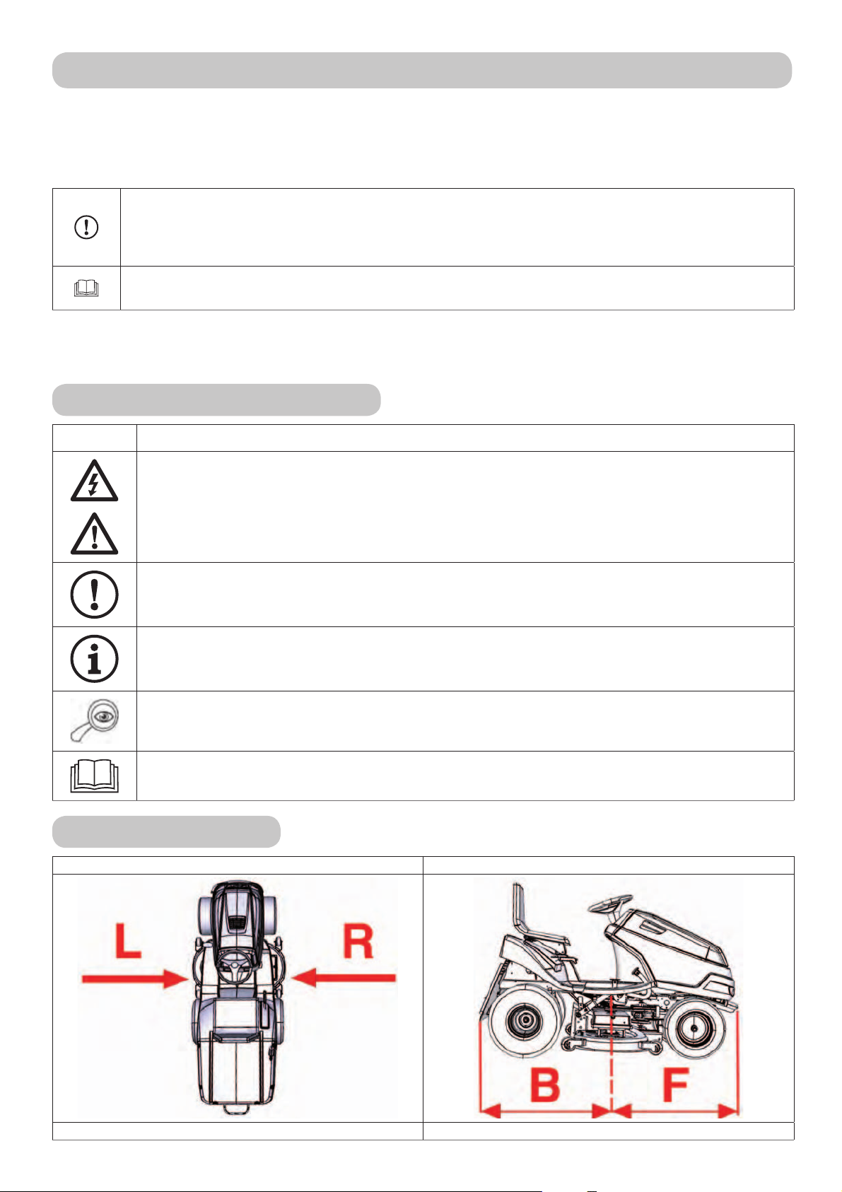
Symbols used in this manual
SYMBOL MEANING
These symbols mean “CAUTION” and “WARNING” and point to factors that could damage
the machine and/or severely injure the user.
This symbol indicates an important instruction, characteristic, practice or issue that must
be followed or kept in mind when setting up, using and maintaining the machine.
This symbol indicates useful information related to the machine or accessories.
This symbol refers to the illustration in the front portion of the manual. It is always
accompanied by the illustration number.
This symbol refers to another chapter of this or another manual. It is usually accompanied
by the number of the chapter to which it refers.
Links to guidelines
Left and right sides Back and front ends
L = left side, R = right side B = back end, F = front end
18
Page 19

1. TECHNICAL INFORMATION
1.1 Use
The AJ92 CHALLENGE machine is a two-axle self-propelled riding mower designed for mowing even,
maintained grass areas with a maximum vegetation height of 10 cm, e.g. in parks, gardens
and sports fields, possibly on minor slopes, on which there are no foreign objects (fallen branches,
rocks, solid items, etc.). The incline of the slope must not exceed 10° (17%).
Any use of this self-propelled mower that is not mentioned in this manual or that
extends beyond the range of use mentioned is considered use that violates the
purpose. The user bears exclusive resp onsibility for all such us e, and the manufacturer is
not responsible for damages arising therefrom. The user is also responsible for adhering
to the conditions presc ribed by the manufacturer fo r operation, maintenance and repair of
this machine, which must be used, maintained and repaired only by persons who are
familiar with it and who have been instructed in safety.
Only manufacturer-approved accessories can be attached to the machine. Using
non-approved accessories will immediately void the warranty.
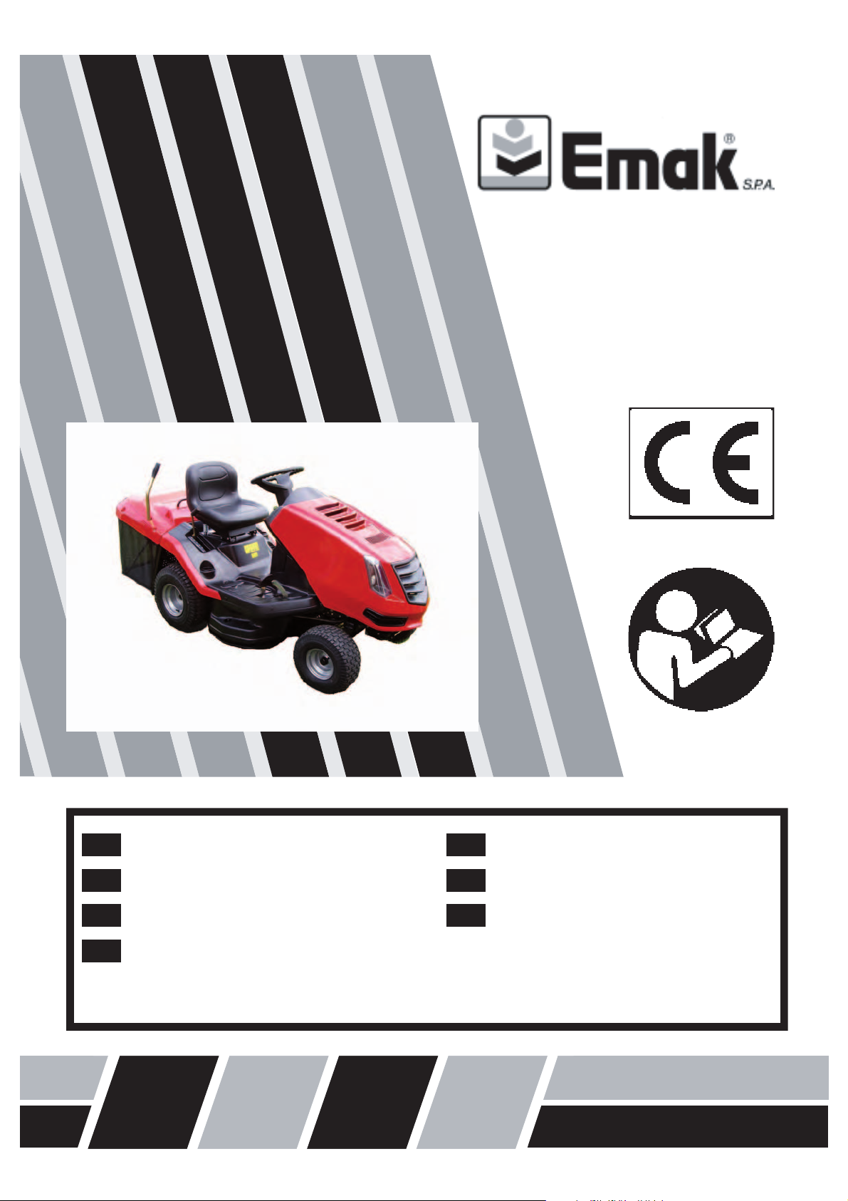
1.2 MAIN PARTS OF THE MOWER
The AJ92 riding mower consists of the following basic sections:
(1) Frame and bumper
1.2
The frame and bumper support most of the machine’s main parts.
(2) Front axle and wheels, including steering mechanism
The front axle allows the wheels to be steered. Steering is done with a steering wheel.
(3) Mowing mechanism
The mowing deck mows and collect s the gras s. It is located under the mac hine. It consists
of a cover, main plate and two mowing blades.
(4) Grass removal tube
It connects the mowing deck with the gr ass catc her. Through here the grass passe s to the
grass catcher.
(5) Transmission and rear-wheel drive
The transmission box and hydrostatic transmission are for shifting gears when driving.
(6) Bypass
The bypass lever is for engaging and disengaging power from the tr ansmission to the re ar
wheels. It is located near the lef t rear wheel and, depending on the machine’s design, is
either in front of or behind the wheel.
(7) Grass catcher
The grass catc her, located at the bac k of the machine, and consist s of a steel tube f rame,
a fabric bag and a dumping lever.
(8) Driver’s area
The comfortable seat allows easy access to all of the machine’s controls.
(9) Bonnet, engine, wiring and battery
The bonnet is a combination of plastic and metal covers that appropriately cover the machine’s
electr ical and mec hanical par ts. L ocated unde r the hood is a 4-str oke petrol engine that is
secured to the frame. The battery is located in the storage space under the steering wheel.
19
Page 20
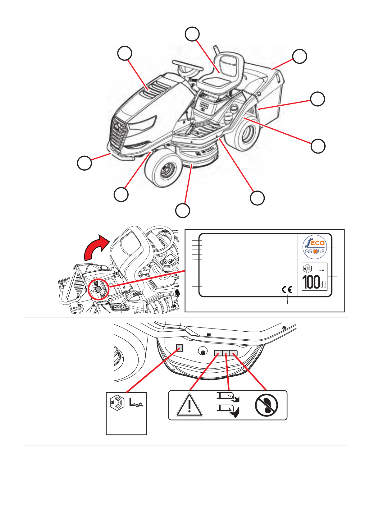
1.3 MANUFACTURING PLATE AND OTHER LABELS USED ON THE MACHINE
1.3.1 MANUFACTURING PLATE
Each self-propelled mower is marked with the manuf ac t ur er’s label, located below the seat . You can
access it by lifting the seat.
1. Mower model
2. Engine model
3. Model year
4. Weight
5. Name and address of manufacturer
1.3.1
1.3.2 OTHER LABELS AND THEIR MEANING
The following labels and stickers are fastened to your machine:
6. EC product conformity regulations
7. Product conformity symbol
8. Manufacturer’s logo
9. Guaranteed noise level according to regulation 2000/14/EC
The vendor will write the serial number of your machine on the back cover of this manual.
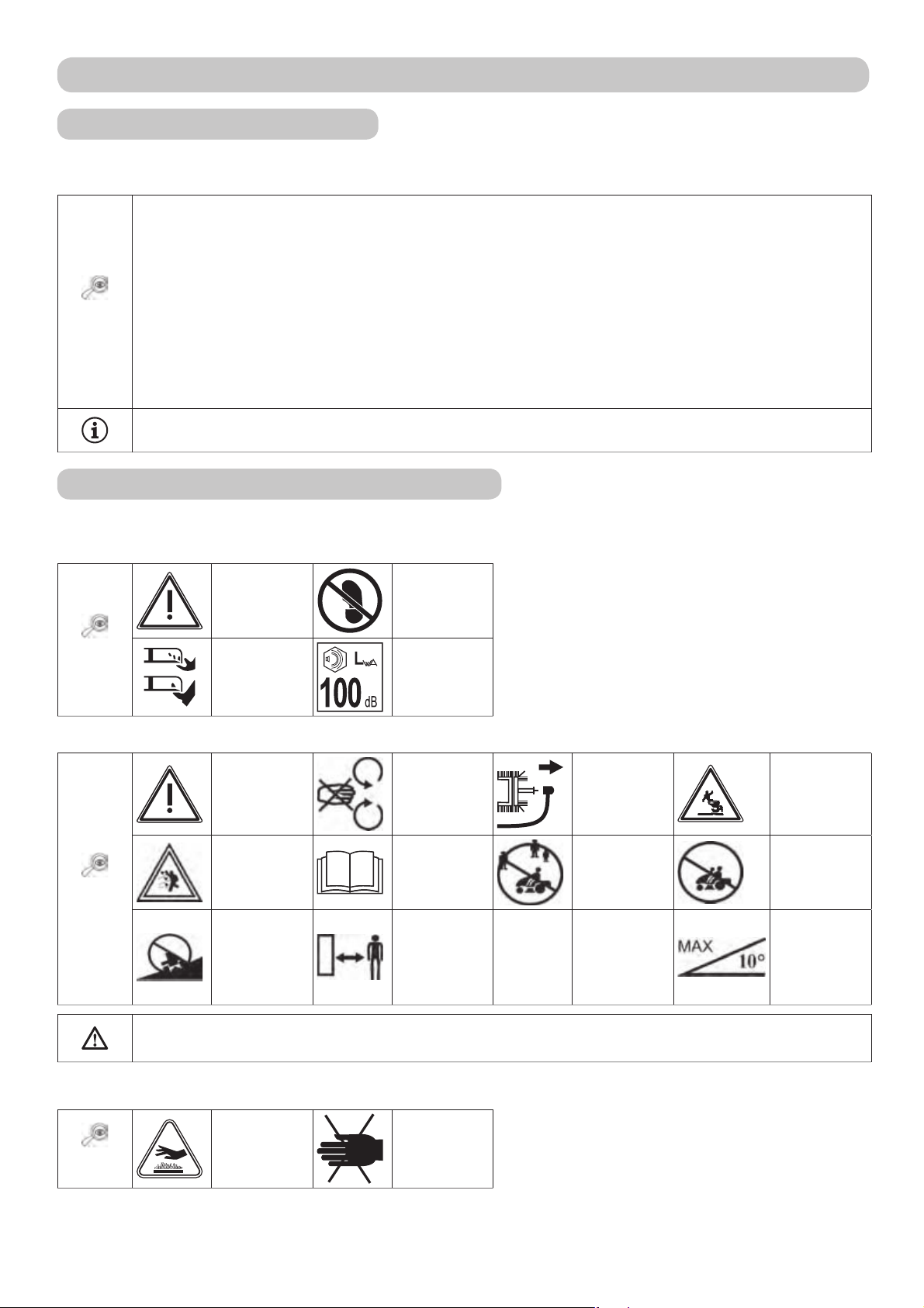
Labels on the left and right side of the mowing deck:
Keep feet
clear
Guaranteed
noise level
1.3.2a
Danger
Rotating
tools
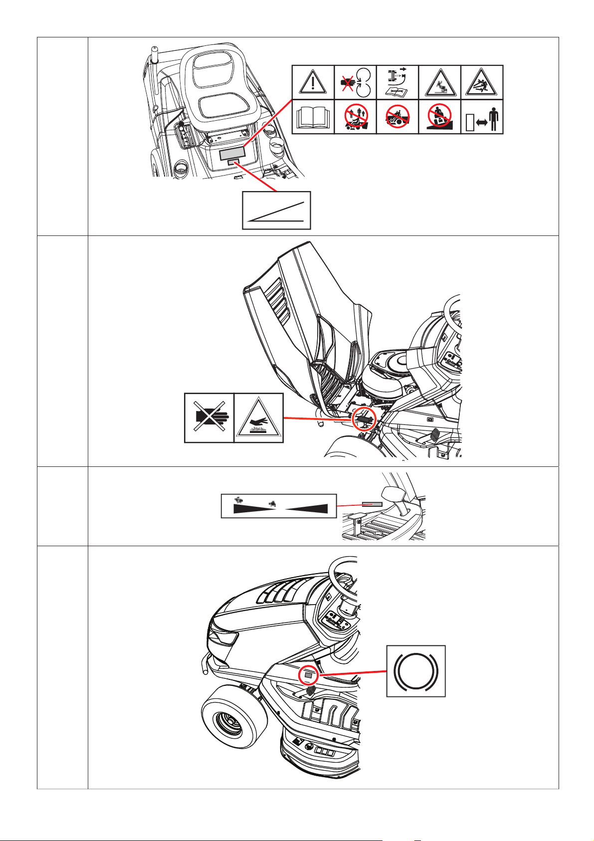
Labels on the canopy below the seat:
Do not
1.3.2b
Danger
Beware
of flying
objects!
Do not drive
across a
slope.
touch during
operation.
Read the
manual
Keep
unauthorized
persons at a
safe distance.
Repair
according to
manual.
Do not mow
near other
people.
Do not
let the
machine run
unattended.
No riders
Maximum
working
slope
It is strictly prohibited to remove or damage labels or symbols attached to the mower.
If a label is damaged or illegible, contact your dealer or the manufacturer for a replacement.
Labels on the left and right side of the machine’s frame under the hood:
1.3.2c
Careful
Hot surface!
Danger of
burns
20
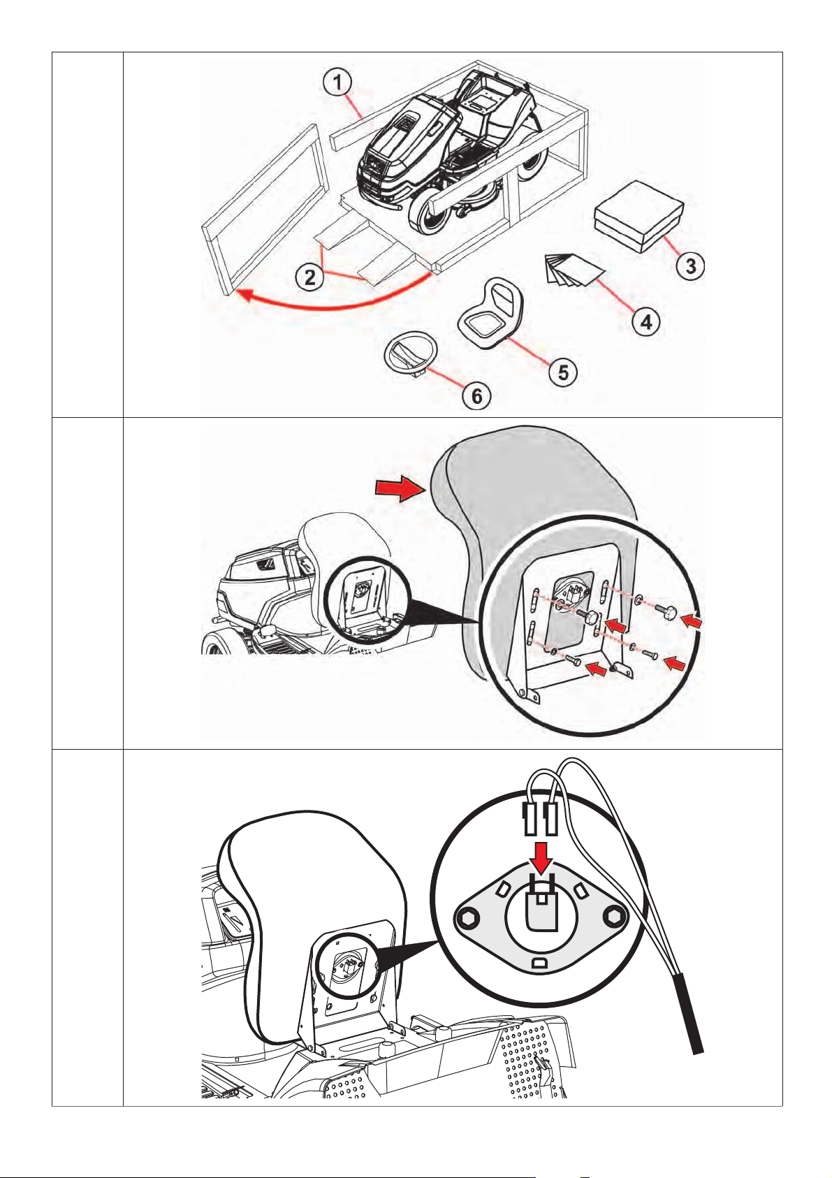
Page 21
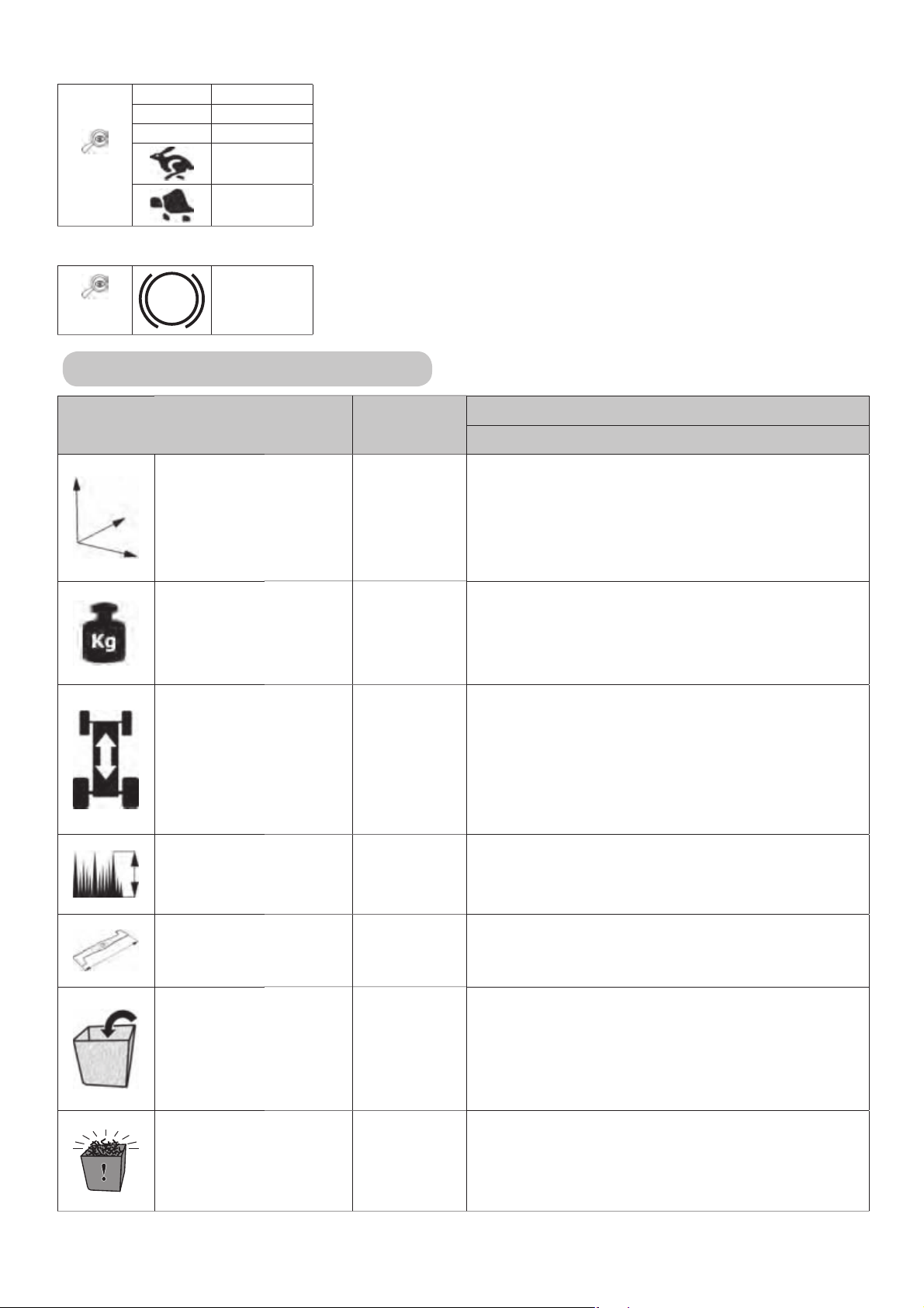
Labels near the undercarriage pedal:
R Reverse
N Neutral
F Forward
1.3.2d
Fast
Slow
Label at the brake pedal:
Brake
1.3.2e
1.4 TECHNICAL PARAMETERS
BASIC SPECIFICATIONS UNIT
Dimensions
(length x width x
height)
MOWER MODEL
AJ92 CHALLENGE
[mm] 950 x 1120 x 2480
Weight [kg] 255
Speed forward /
reverse
[km/h] 9 / 7
Cutting height [mm] 30 - 90
Cutting stroke [mm] 92
Grass catcher volume [l] 300
Full grass collector
indicator
--- Buzzer
21
Page 22

BASIC SPECIFICATIONS UNIT
MOWER MODEL
AJ92 CHALLENGE
Wheel
dimensions
Rear 18 x 8,5-8
["]
Fuel tank capacity [l] 7
Battery type --- 12V 24 Ah
Front
Guaranteed acoustic
output level L
WA
[dB] < 100*
Declared noise
emission level at the
operator L
per EN
pAd
[dB] < 90*
ISO 11201
* - For exact values, see the charts on the next page.
15 x 6-6
AJ92 Riding mower
Engine
rpm±100
(min-1)
Declared emission
level of ac.
pressure at the
place of operation
L
(dB)
pAd
EN ISO 11201
Guaranteed
emission level
of acoustic
power L
WA,G
(dB)
Vibration acceleration aggregate
value (m.s-2) according to
EN 1033+A1
total vibrations
a
vd
transferred to the
arm a
BS 3130 2700 85 + 1 100 1.0+0.5 7.0+3.0
BS 4155 2700 86 + 4 100 1.2+0.5 <2.5
BS 4175 2700 85 + 4 100 0.8+0.4 5.0+2.0
BS 7160 2700 84 + 2 100 0.9+0.4 2.9+1.4
Explanatory notes:
Engines:
BS 3130 Briggs & Stratton 3130 POWERBUILT
BS 4155 Briggs & Stratton 4155 POWERBUILT
BS 7160 Briggs & Stratton 7160 INTEK
hvd
22
Page 23

2. OCCUPATIONAL SAFETY
CHALLENGE brand AJ92 s elf-prope lled mowers are manufac tured accor ding to applicable European
safety norms. The manufacturer confirms this in the Declaratio n of Complianc e include d at the end
of this manual ( 10).
If this machine is used properly and according to the manual, it is very safe.
If the user does not adhere to work safety and does not heed the warnings in this
manual, this self-pro pelled lawn mower can sever a hand or a foot, or even hurl
objects, le ading t o se riou s pe r son al injury or de ath, d amage or de s truc t ion of t he
machine, or of some of its parts or accessories.
2.1 SAFETY INSTRUCTIONS
The user bears primary responsibility for his or her own safety and that of other people during operation
of the mower. The machine’s manufactur er bears no r esponsibilit y for pers onal injury, damage to the
machine or ecological damage c aused by use and ope ration not in keeping with all safety ins truc tions
given in this manual.
2.1.1 General safety instructions
! This machine may be operated only by persons 18 years or older who are familiar with this user
manual. The machine must never be operated by unauthorised persons, who hav e not read the user’s
manual and who are not able to correctly and safely control the machine.
! The use r of the machine is responsible f or the safet y of persons pr esent in the machine’s operating
area.
! It is prohibited to perform any technical modifications without prior written consent of the manufacturer .
Unauthorized modifications may lead to hazardous working conditions and void the warranty.
! Adhere to all fire safety regulations (
2.4).
! Do not remove the safet y sticker s and labels from t he machine. Check that they are in their pr oper
locations.
! Do not go near or underneath the machine if it has been raised and is not sufficiently secured against
falling or overturning.
! Subjecting components of the grass catcher to stress can damage them, reduce their function or cause
objects to fall out of the c atc her. Therefore, chec k them r egular ly acc or ding to the re c ommendations
in this manual.
! Always switch off the mowing mechanism and the engine and remove the key from the ignition when:
cleaning the machine
unclogging the mowing mechanism
checking the machine for damage or repairing it after driving over a foreign object
checking for the cause of excessive vibration
repairing the engine or other movable parts (also disconnect the ignition cable)
2.1.2 Before using the machine
! Do not use the machine if it is damaged or missing safety equipment. All protective covers and safety
elements must be in place at all times. Do not remove or disable any safety devices.
! Regularly check that protection devices and safety elements work properly.
! Do not use the machine when under the influence of alcohol, medication or narcotics.
! Do not work with the mac hine if you suff er dizziness or f ainting, or if you are otherwise weakened or
unable to concentrate.
! Before op erating the machine, thoroughly familiarize yourself with all the contr ols and master their
operation so that, if necessary, you can immediately stop the machine or shut off its engine.
! Do not change the settings of the engine regulator or engine speed limiter.
23
Page 24

! Befo re working with the machine, clear the mowing sur face of all stones, wood, wires, bones, fallen
branches and other foreign objects that the machine may throw during operation.
! Repair all defects bef or e f urther use. Befor e s tarting work, thoroughly inspe ct the V-belt tension, the
sharpness of the mowing blades and the cleanliness of the mowing mechanism cover.
! Before using the machine, visually check that the machine parts are not damaged or missing or visibly
loosened.
! Prior to using the machine check that the brakes work and if necessary have them adjusted or repaired.
2.1.3 While using the machine
! The machine must not be used for work on slopes that have an incline greater than 10° (17%).
! Transporting other people, animals or objects on the machine is prohibited. Objects may be transported
only on a trailer approved by the machine’s manufacturer.
! Even when leaving the machine for a short time, always remove the ignition key.
! If you are driving the machine out side the mowing area, always shut off the mowing mechanism and
raise it to transport position.
! Never mow near dumps, holes or river banks. If a wheel gets too close to th e e dge of a hole or ditc h,
the mower may suddenly overturn.
! While working, keep clear of molehills, concrete supports, tree stumps and the curb stones of gardens
and street s. These may come into co ntact with the blade s and damage the mowing mechanism and
the machine itself.
! If you run into a solid objec t, stop t he mac hine, shut of f the mowing mechanism and the engine, and
check the whole machine, especially the steering mechanism. If necessary, repair any damage before
restarting the machine.
! Where possible, avoid working with the machine on wet grass. Reduced traction may cause skidding.
! Avoid obstacles (e.g., sudden changes in slope, ditches, etc.) that could overturn the machine.
! Do not try to maintain the machine’s stability by stepping on the ground.
! Use the machine only in daylight or under sufficient artificial light.
! Do not drive the machine on public thoroughfares.
! Whe n operating the mac hine, do not wear loose clothing or shor t trous er s; wear strong, closed work
shoes. Never operate the machine barefoot or in sandals.
! Do not leave the engine running in enclosed spaces. Exhaust gases contain poisonous substances that
have no odour but are nonetheless fatal.
! Do not place your hands or feet under the mowing mechanism cover . Never bring any part of your body
near the machine’s rotating or moving parts.
! Do not start the engine without the exhaust pipe.
! The noise that occurs during mowing does not ordinarily exceed the highest acoustic pressure
and volume values shown in this manual (
1.4). However, under some conditions, due to terrain
characteristics, the noise level may briefly exceed specified levels.
! The manufacturer recommends wearing ear protectors while operating the machine. Stress placed on
the auditory organ s by high volume levels or the long-term ef f e cts of noise can per manently damage
hearing.
! Always give your full attention to driving and the other ac tivities involved in using the machine. The
most common ways to lose control over the machine are:
Loss of traction.
Driving too fast; not adapting speed to the surface conditions and characteristics.
Abrupt braking that can lock the wheels.
Using the mower for purposes other than those intended.
2.1.4 After working with the machine
! Always keep the machine and its accessories clean and in good working order.
24
Page 25

! The rot ating blades are sharp and may cause injur y. When handling the blades, wrap them or wear
protective gloves.
! Regularly check the nuts and bolts that hold the blades, and mak e sure they are tightened to the right
level of torque (
! Pay special attention to the self-locking nuts. Af ter a nut has been removed twice, its self-locking
ability is reduced, and it must be replaced with a new one.
! Regularly check the c o mp onents and, when necessary, replace them ac c o r ding to th e manuf acturer’s
recommendation.
6.3.6).
2.2 SAFETY INSTRUCTIONS FOR WORKING ON SLOPES
Slopes are a main cause of accidents, loss of control and overturning. These can lead to severe injury or
death. Always use extra caution when mowing on slopes. If you are not sure or are unable to mow on a
slope, don’t do it.
! The self-propelled mower can be used on slopes of no more than 10° (17%), when using the 4x4 drive
at a maximum slope of 1 5 ° ( 2 7 %) and only ver tically, i.e., upward or downward. More information
5.5.4.
! Extra caution is necessary when turning. Do not turn around on a slope unless absolutely necessary.
! Beware of holes, roots or uneven ter rain. Uneven terrain may cause your machine to overturn. Tall
grass may conceal dangerous ob stacles. Therefor e, remove all obstacle s from the mowing surface
ahead of time.
! Select a speed that will not require you to stop on a slope.
! Be very careful when attaching the grass catcher or other attachments. They may reduce the machine’s
stability.
! Always move slowly and smoothly on a slope. Do not change speed or direction suddenly.
! Avoid starting or stopping on a slope. If the wheels lose tr action, turn off power to the blades and
slowly drive down the slope.
! Ac c eler ate ver y sl owly and caref ully on slope s, to prevent the machine from lurc hing. Befor e a slop e,
always reduce the engine speed. Especially when driving downward, reduce the speed to the minimum
for using the transmission’s braking effect.
2.3 CHILD SAFETY
If the operator is not alert to the presence of children, a tragic accident may occur. The mower’s
movement attracts their attention. Never assume that children will stay where you saw them last.
! Never leave children unsupervised in mowing areas.
! Never allow children to operate this machine!
! Be alert and ready to stop your machine in case of an emergency.
! Before and and while backing up, look to the rear and at the ground.
! Never transport children on the mower. They can fall and be severely injured or dangerously interfere
with your operation of the mower. Never allow children to operate the machine.
! Take extra care in areas of limited visibility (near trees, bushes, walls, etc.).
2.4 FIRE SAFETY
While using the mower, you must observe all work and fire safety rules relevant to this type of machine.
! Regularly r emove flammable mater ials (dry grass, leaves, etc.) from the ar ea of the engine exhaus t,
battery and anywhere where they might come into contact with petrol or oil, ignite and set the machine
on fire.
! Allow the mower’s engine to cool before storing it in an enclosed space.
! Use extra c aution when working with petrol, oil and other flammable substanc es. These are highly
flammable substances, and their fumes are explosive. Do not smoke while working. Never unscrew the
fuel cap, and never add fuel when the engine is running or is warm, or if the machine is in an enclosed
space.
25
Page 26

! Check the fuel flow before use; do not fill the tank up to the neck. Engine heat, sun and the expandability
of fuel may lead to overflow and r esult in fire. Use only approved container s for storing flammable
substances. Never stor e th e machine or f uel c ont ainer near any heat sour c e. Use e x tr a c aution when
handling the batter y. Batter y gases ar e highly explosive. Do not smoke or use an open flame when
handling the battery, as this may cause serious injury.
26
Page 27

3. PREPARING FOR OPERATION
3.1 UNPACKING AND CONTENT INSPECTION
The self-propelled mower is delivered in a fabric cover (1). Some parts of the machine have been
dismantled for transp ort at the factor y, and they must be installe d before operation. The machine is
unpacked and prepared for operation by the dealer as part of pre-sale service.
- Af ter delivery, immediately check to see if the packaged mac hine is damaged. If there is
damage, notify the carrier. If a claim is not made on time, it cannot be honoured.
- Check to see that the machine is the model you ordered. If it is the wrong model machine,
do not unpack it, and immediately alert the supplier.
After r emoving the cover, carefully re move the machine from the pallet. This requires preparation of
ramps (2) to avoid damage to par ts of the machine. Make sure that there is no shipping damage. Also
unpack all dismantled parts and inspect them.
1. Fabric cover
2. Ramps
3. Grass catcher
3.1
The basic package includes:
Mower
Steering wheel (6)
Seat (5)
The grass catcher (3) (is partially disassembled in the cardboard box, with a hitch and joining material.
Documentation (4) (packing list, user manual for mower, engine manual, battery manual and service
book)
4. Documentation
5. Seat
6. Steering wheel
Ramps (2) are not included with the machine.
3.2 DISPOSAL OF PACKAGING
After unpack ing the accessories, make sure you properly dispos e of and recycle
the packaging material.Comply with applicable waste disposal laws in the user’s
country.
Disposal can be entrusted to a specialized company.
3.3 ASSEMBLING PACKED UNITS
Because it is technic al work, your dealer will prepar e the mower for ope ration (according to
the following instructions).
Before starting installation, remove all protective materials, place the mower on a flat surface,
and align the front wheels in forward position.
27
Page 28
3.3.1 STEERING WHEEL, SEAT AND BATTERY
a) Fasten the seat:
Place the seat in its place on the machine and secure it using four bolts, pre-mounted
in the seat. Before tightening the bolts, set the desired position of the seat to match
your body size.
b) Connect the cable to the safety switch:
Connect the electrical cable to the switch connector at the bottom of the seat.
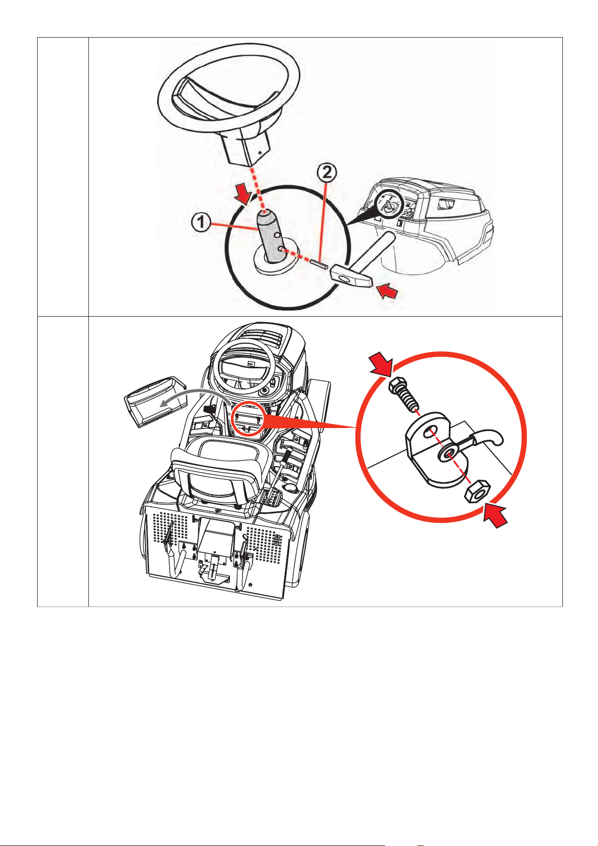
c) Install the steering wheel:
Place the wheel on the column (1) and turn it so that the holes in the steering wheel
and column meet.
Insert the included peg into the hole (2) and pound it with a hammer.
d) Connect the battery:
Bolts and rubber bat ter y caps are lo cated in the bag with the documentation and
other joining material.
Turn the lever of the storage space c over located under the ste ering wheel to open
the cover and take it out.
Loosen the bolts on the battery’s pole terminals.
Attach the red cable to the battery’s positive (+) pole and secure it with the bolt.
Attach the brown cable to the battery’s negative (–) pole and secure it with the bolt.
Place the rubber caps on to both leads.
Put the storage space cover back and secure with the lever.
3.3.1a
3.3.1b
3.3.1c
3.3.1d
- Connecting the cables backwards can damage the machine.
- When disconnecting the battery, always disconnect the negative (–) terminal first.
- When installing, using and maintaining the battery , follow the instructions described in the
battery manual. At the same time, observe all of the manual’s safety instructions.
3.3.2 GRASS CATCHER
The grass catc her is de livered in a se parate b ox. Some of its parts have been dismantled for transp ort
and must be assembled first. Later chapters give a rough outline on assembling it. The complete process
is shown on the DVD that is included or can be sent upon request.
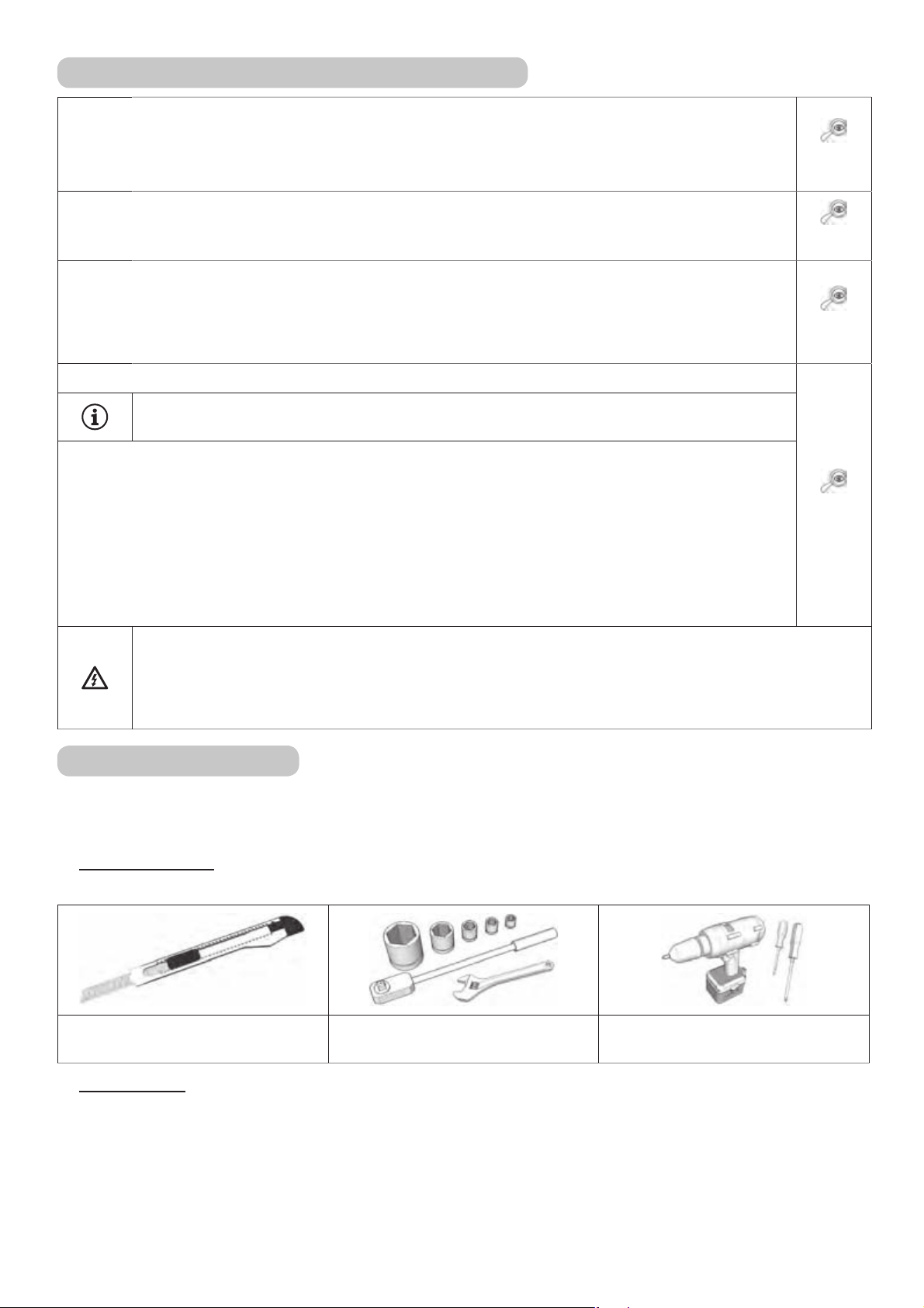
TOOLS NEEDED
Prepare the following tools for assembling the catcher:
A knife for removing packing
material
UNPACKING
A set of hexagonal socket
wrenches and hex wrenches
Phillips screwdrivers or an
electrical hand screwdriver
Remove the packing material. First take out the lid, frame and sack and then the wr apped individual
parts. Unpack these parts and clearly organize them in an appropriate place.
28
Page 29
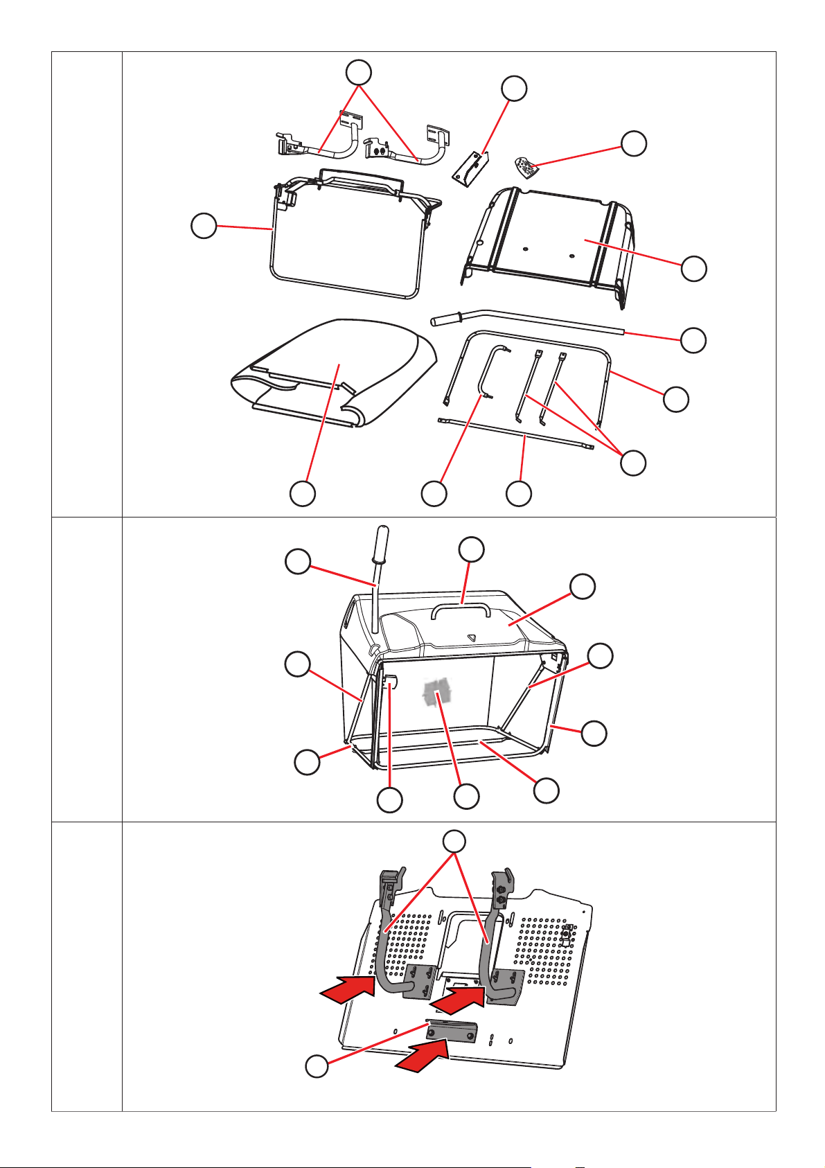
PACKAGE CONTENTS
(1) - Lid
(2) - Lifting lever
(3) - Lower tube
(4) - Side struts
(5) - Lower brace
(6) - Handle
(7) - Sack (mesh)
(8) - Frame
(9) - Grass catcher hitches
(10) - Hitch
(11) - Joining material
Four replacement shear pins for the cutting blades are packaged with the grass
catcher.
Store these pins for later use.
3.3.2a
GRASS CATCHER - MAIN PARTS (TERMINOLOGY)
(1) - Lid
(2) - Lifting lever
(3) - Lower tube
(4) - Side struts
(5) - Lower brace
(6) - Handle
(7) - Sack (mesh)
(8) - Frame
(12) - Grass catcher hitch switch
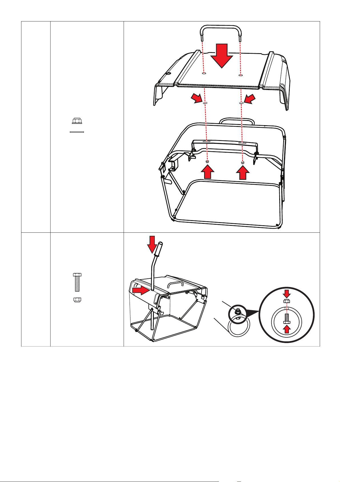
INSTALLING THE GRASS CATCHER
Screw the grass catcher hinges (9) and hinges (10) on to the rear plate.
- On some machines, the hinges (9) are already pre-mounted on the rear plate.
- Hinge (10) is attached only if a trailer is used.
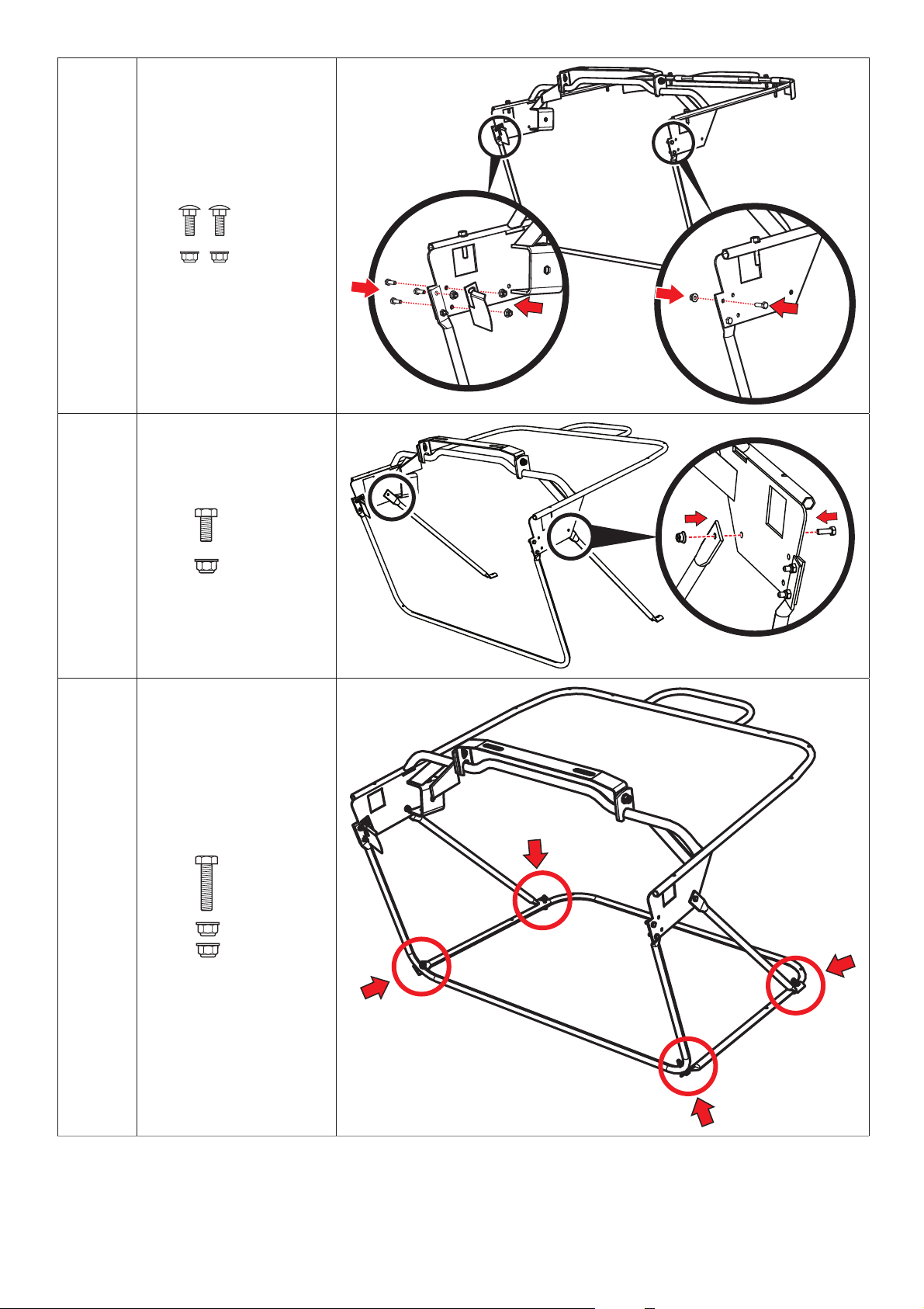
Insert M5x16 bolts into the top holes in the front frame at tachment brackets at t he top,
and secure in place with a washer and nut and tighten lightly. Pull tight the pre-mounted
bottom bolt s. On to the right side of the fr ont frame tube, into the lower hole, using two
bolts screw on the grass catcher hitch switch.
3.3.2b
3.3.2c
3.3.2d
Screw on the side st r ut s of the gr as s c atc her. The struts ar e attached to the inner side of
the grass catcher using M5x16 bolts and nuts.
Screw the bot tom tube to the f rame. For easier as sembly, we recommend that the grass
catcher is turne d upside down. Attach it to the side braces and to t he front frame tube
using M5x3 bolts and nuts.
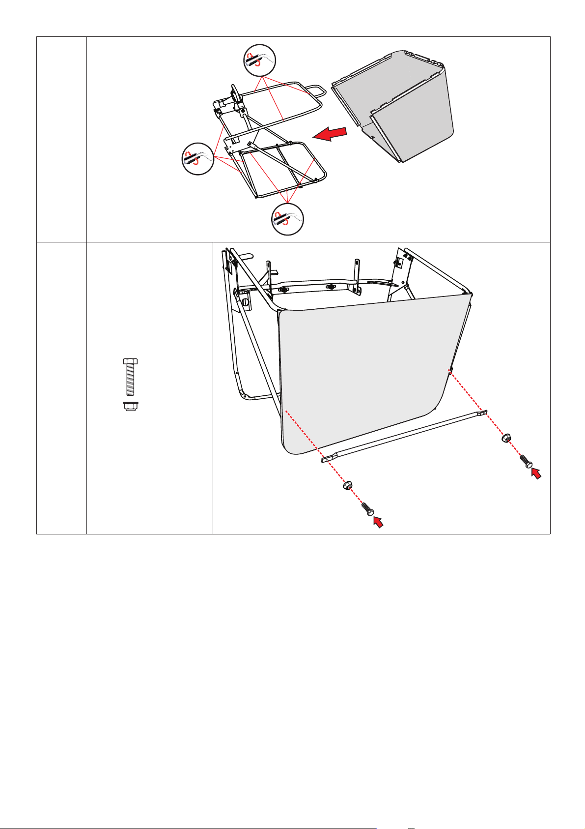
Slide the grass catcher s ack on to the frame. Pull the rubber sides of th e sack over the
tubes.
29
3.3.2e
3.3.2f
3.3.2g
Page 30
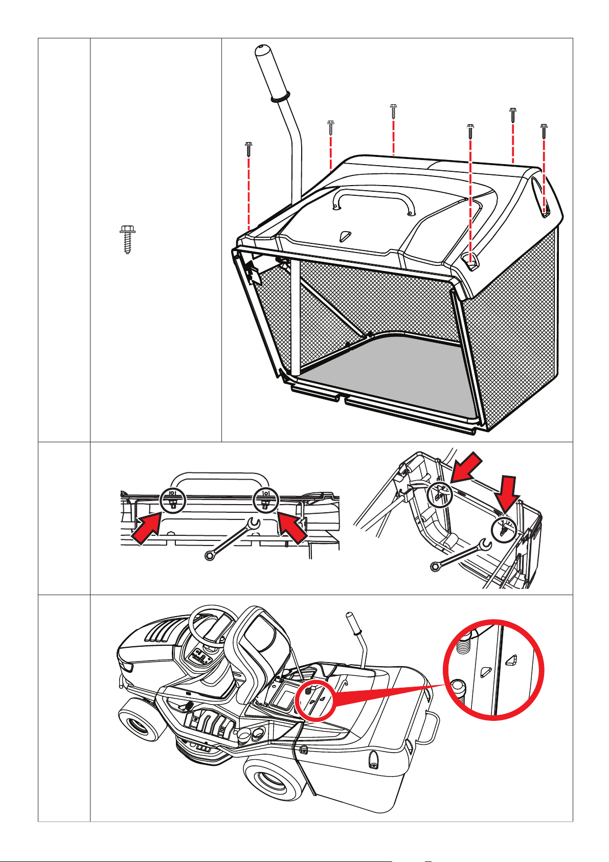
Screw on the lower brace from the bottom side of the grass catcher.
Into the openings in the lid insert the handle and slide washer s on to its threade d ends.
Insert the piec e assembled in this way through the openings in the top bracket on the
frame and secure the handle using nuts. Do not tighten them yet!
Bolt the lid to the frame and tighten the bolts.
Insert the emptying lever into the holes in the brace inside the catcher.
Into the lower end of the lever inside, insert a bolt and push its thr eade d portion through
the hole. Secure it from above with a nut and tighten it.
Firmly tighten the nuts sec uring the handle and tighten the nut s se cur ing the top brac ket
of the frame. This completes the installation of the grass catcher.
BALANCING AFTER INSTALLATION
Take hold of the grass catcher and hang it on the hangers on the rear plate of the machine.
Check for the co rr e c t alignment of the gra ss c atc her with the mudguar d us ing the arr ows
pressed in the grass catcher lid and the machine cover. Correct any imbalance by loosening
the bolts in the front tube and/ or the bolts in the side braces, ev ening it up and retightening
the bolts.
3.3.2h
3.3.2i
3.3.2j
3.3.2k
3.3.2l
3.3.2m
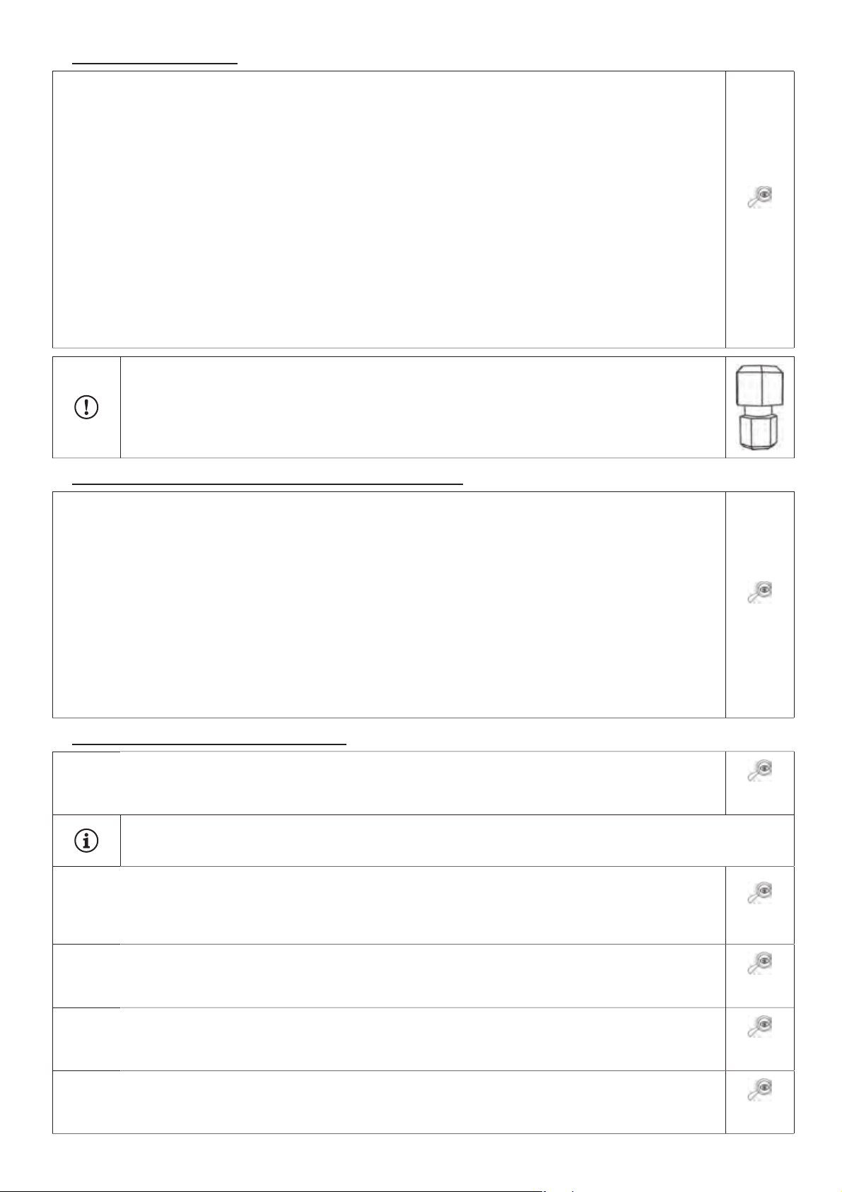
On a properly adjusted grass c atcher the spac e bet ween the r ear plate of the machine and
the front frame tube (8) (
If it is not possible to align using the above described me tho d, perform the adjustment by sliding the
3.3.2b) is no greater than 5 mm.
grass catcher hitch on the rear plate or the bolts and brackets on the top side of the hitch.
3.4 INSPECTING BEFORE STARTUP
3.4.1 CHECKING THE ENGINE OIL
Before checking the oil, the tractor must be in a horizontal position. The oil cap can be accessed by lifting
the seat. Unscrew the dipstick, wipe it clean, reinsert it and screw it back in. Then unscrew it again and
read the oil level.
Oil level on dipstick:
(1) - (ADD) oil is low
(2) - (FULL) oil is full
The oil level must be between the t wo marks on the dipstic k. If it is not, add motor oil until it reaches
the “FULL” mark. The oil type is designated in a separate manual from the engine manufacturer.
The oil must be checked before every ride.
3.4.2 BATTERY INSPECTION
Check the battery according to the manual provided by its manufacturer.
30
Page 31

3.4.3 FILLING THE FUEL TANK
For safety r easons, the mower is transported without f uel, and it is necessary to f ill the tank before
star ting up for the f irs t time. The fuel tank is loc ated under the fr ont hood and has a c apacit y of 7.5 l
of fuel.
- Use only fuel of the octane rating designated in the engine manual. Defects caused by
improper fuel are not covered by the warranty!
- Fill the tank only when the engine is switched off and is cool. Fill the tank in a well-ventilated
area.
- When handling fuel, do not eat, smoke or use an open flame.
- For filling the tank, use a funnel intended for use with fuel.
- Make sure not to spill any fuel when filling the tank. Spilled fuel is highly flammable. If any
fuel spills, wipe it up until dry.
- Store fuel out of the reach of children.
Filling process:
Remove the fuel tank cap. Open it slowly, becaus e the tank may contain
pressurized petrol fumes.
Insert the funnel into the filling port and pour in fuel from a canister.
After filling the tank, always wipe dry the cap and the are a ar ound it. It is
appropriate to check the fuel level through the lines.
We also recommend cleaning the tank itself regularly, because any
contaminants in the fuel can cause engine breakdown.
3.4.4 CHECKING TYRE PRESSURE
Before using the machine, check the air pressure in the tyres.
The air pressure in the front and rear tyres must be within the range
of 80 -140 kPa. The difference between the individual tyres can be
± 10 KPa.
Do not exceed the maximum pressure marked on the tyres that are being used.
31
Page 32

4. CONTROLLNG THE MACHINE
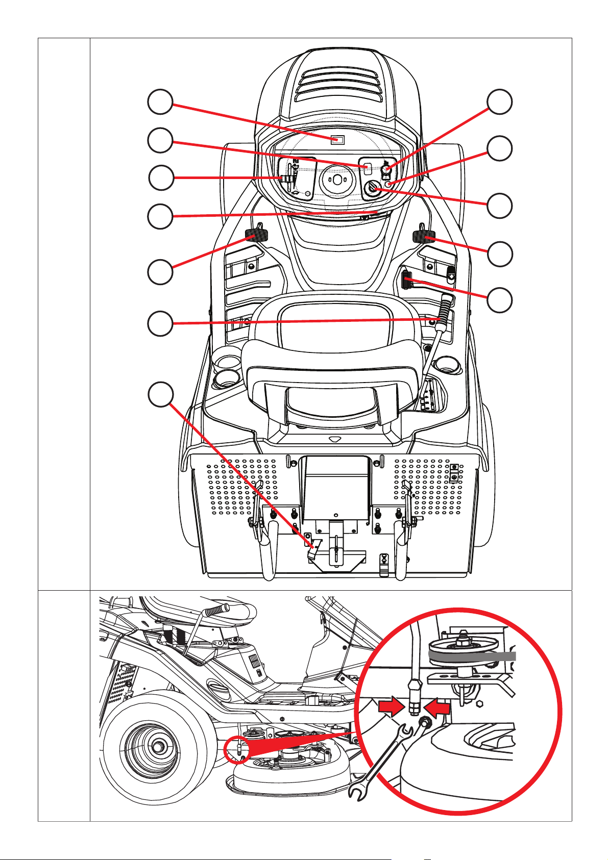
4.1 CONTROL LAYOUT
(1) Throttle lever
(2) Motor hours counter
(3) The mowing function activation switch when the grass catcher is full
(4) Mowing deck activation switch
(5) Indicator light showing that the brake pedal is stepped on and the parking brake is
engaged
4.1
(6) Main power switch
(7) Forward drive pedal
(8) Reverse drive pedal
(9) Parking brake controller
(10) Brake pedal
(11) Mowing deck elevation adjustment lever
4.2 DESCRIPTION AND FUNCTION OF CONTROLS
4.2.1 STANDARD CONTROLS
(1) ACCELERATOR LEVER
Regulates engine RPM. Has the following three positions:
STARTER* To cold start the engine
MAX Maximum RPM
MIN Minimum RPM (idle)
* Only on machines with engines BS13, BS17, KO15, TE17 and HO16
(2) ENGINE HOUR GAUGE
The operational hour counter implicitly displays the total number of motor hours. Press the Mode button
to switch between the following service functions:
TMR 1 - individual trip counter. Zeroing is carried out by
holding down the Mode button for 6 seconds.
OIL CHG - oil change. The function includes two intervals
for an oil change. The first is after the first
5 hours (oil change after the machine has
been run in) and is displayed only once. The
second is after 25 hours (standard oil change ).
AIRFILTER SVC - cleaning or changing the oil filter, the interval
is set to 50 hours.
Two hours before the end of the set interval the display will show a message lasting 10 seconds.
At the end of the interval the display will show a message NOW.
Zeroing of any of the above mentioned alarms is carried out by holding down the Mode button for
6 seconds.
32
Page 33

- Manipulation of the counter entails loss of warranty; the hours of movement clock is fitted
with a protective seal.
- If the hours of movement clock is out of action, inform your service agency immediately.
(3) MOWING FUNCTION CONTROL SWITCH WHEN GRASS CATCHER IS FULL
The AUT/MAN switch turns the mowing function (of the mowing mechanism) on and off when the grass
catcher is full.
In the MAN position, mowing is on all the time, and if the grass catcher is full, the removal tube can fill
with clippings. For this reason this position is intended only for short term use to complete the mowing
of very small remaining areas.
If the machine is equipped with an acoustic indicator (buzzer), then it is automatically
activated when the basket is full.
In the AUT position, mowing is switched off automatically at the moment the grass catcher is full.
Position Grass catcher full Mowing mechanism and gear
AUT NO ON
AUT YES OFF
MAN NO ON
MAN YES ON
(4) MOWING MECHANISM SWITCH
Pulling the switch upward turns the mowing mechanism on. Pressing downward shuts the mowing
mechanism off.
OFF
ON Turning on the mowing mechanism
(5) INDICATOR FOR THE BRAKE PEDAL AND PARKING BRAKE
This indicator signals that the brake pedal has been pressed or the parking brake engaged.
Parking brake engagement signal
Brake pedal indicator
Turning on the mowing mechanism / mowing mechanism is
off
33
Page 34

(6) MAIN SWITCH
Turns the engine on and off. It has the following 4 positions:
Ignition is off / turn off ignition
Turning the bonnet headlights on and off
Ignition is on, the engine is running.
Engine start-up – start-up position
(7) FORWARD DRIVE PEDAL
This pedal controls the drive wheels and regulates the machine’s forward movement.
The closer to t he f loor you pre ss the p edal, the fast er the mac hine goes, and
vice versa.
When released, the pedal automatically returns to the neutral position and the
machine stops.
For more details
ATTENTION: A forward/backward change in direction is possible only after the
machine has stopped!
(8) BACKUP PEDAL
This pedal controls the drive wheels and regulates the machine’s backward movement.
The closer to t he f loor you pre ss the p edal, the fast er the mac hine goes, and
vice versa.
When released, the pedal automatically returns to the neutral position and the
machine stops.
For more details
5.5.
5.5.
A forward/backward change in direction is possible only after the machine has
stopped!
(9) PARKING BRAKE LEVER
The parking brake lever has two positions. In position (1), the brake is inactive.
When it is moved to position (2) while pressing the brake pedal, the parking
brake is engaged.
Stepping on the brake pedal disengages the parking brake, automatically
releasing the lever and moving it to position (1).
34
Page 35

(10) BRAKE PEDAL
Stepping on the brake pedal stops the mower.
The pedal is also used when starting the machine, which can be star ted
only when the brake pedal is pressed.
(11) MOWING MECHANISM HEIGHT ADJUSTMENT LEVER
This lever sets the height of the mowing mechanism from the ground.
The lever has 6 work positions, which cor r esp ond to a mowing height of 3 to
9 cm.
The higher the lever’s position number, the taller the grass will be after cutting.
When driving the machine without mowing, the lever must be set to 7.
(12) BYPASS LEVER – FREE MOVEMENT OF REAR WHEELS
The by-pass lever serves to dise ngage the t r ans miss ion f or t he r e ar whe e l dr ive and is use d to pus h or
pull the machine without using the engine. The lever is located on the rear plate of the machine and has
the following two positions:
Position Rear wheel drive Use
(0) DISENGAGED
(1) ENGAGED
Lever is extended - for pushing the
machine
Lever is inserted - for driving the
machine
4.2.2 OPTIONAL CONTROLS
(1) STARTER
For cold starting the engine.
Machines with engines BS13, BS17, KO15, TE17 and HO16 are not equipped
with separate starters.
(2) BUZZER
The buzzer gives off an audible signal when the grass catcher is full.
After the audio signal that the catcher is full, power to the mowing mechanism is not shut off!
35
Page 36

5. OPERATING THE MACHINE
Good information to know before starting your mower for the first time:
The mower is equipped with safety contacts that are triggered:
- by a switch located below the seat
- a switch mounted in the grass catcher or deflector
- the grass catcher fill switch
- the brake pedal switch
The engine automatically stops if the operator leaves the seat and the machine is not
secured by the parking brake.
The engine can be st ar ted only when the mowing mechanism is tur ned of f and the gras s
catcher or deflector is installed and the brake pedal is pressed. The deflector prevents
clippings from entering the intake tube to the grass catcher.
5.1 INSPECTING BEFORE STARTUP
Before starting the mower, check the following:
The engine oil level ( 3.4.1)
The battery status ( 3.4.2)
The fuel level ( 3.4.3)
The tyre pressure ( 3.4.4)
5.2 STARTING THE ENGINE
a) Step on the brake pedal.
b) Set the mowing mechanism height lever to position “6”.
c) On motorized machines, open the fuel cap (only on machines with 15.5-hp BS15 engines).
d) Set the accelerator lever as follows:
- On machines with 2-cylinder engines, to the “MAX” position
- On machines with 1-cylinder engines, to the “STARTER” position
e) Pull out the starter (only on engines with 16 hp or more)
f) T urn the key to the “Start engine” position to turn on the ignition. Let go of the key after starting. The
key will automatically return to the “Ignition ON” position.
As soon as the engine turns over, let go of the ignition key. The starting time must not
exceed 10 seconds. Otherwise the switch may be damaged.
Never use fixed external starters to start the machine. This could damage the
electrical wiring. It is possible to connect a higher capacity 12V battery.
g) Plug in the starter (only on machines with 2-cylinder engines)
h) Slowly move the accelerator lever to “MIN” position.
Let the engine run for a few minutes before engaging the mowing mechanism.
- Never let the engine run in a closed or badly ventilated area. Exhaust gases can endanger
your health.
- Keep your feet, hands and loose clothing away from exhaust and moving parts.
36
Page 37

5.3 SHUTTING OFF THE ENGINE
a) Move the fuel control lever to the “MIN” position.
b) If the mowing mechanism is turned on, shut it off by pressing the switch downward.
c) Shut off the engine by turning the key to the “STOP” position and remove the key from the ignition.
If the engine is too hot, let it idle for a while.
- Never shut the engine of f just by leaving the driver seat . Leaving the key in the
ignition in “ON” position may damage the electrical system.
- Always turn the key to the “OFF” po sition and remove it from the ignition. This
prevents children and unauthorized persons from starting the machine.
- Before turning off the ignition, slow the engine to idle in the case of self-ignition. Not
doing this can damage the engine and exhaust.
- Never disconnect the battery cables while the motor is running! This could damage
the motor regulator.
5.3.1 LEAVING THE MACHINE WITH THE ENGINE RUNNING
If you want or need to leave the machine for a while ( to remove obstacles, etc. ) and you intend to continue
work afterward, you can dismount the machine and leave the engine running. This conserves the
battery.
Conditions for dismounting the machine with the engine running:
the mowing mechanism is off
the fuel control lever is in the “MIN” position
the gear is in neutral and the hand brake is activated (the brake indicator light is on)
5.4 TURNING THE MOWING MECHANISM ON AND OFF
5.4.1 TURNING THE MOWING MECHANISM ON
Move the accelerator lever to “MAX” position.
Use the mowing mechanism height lever to set the mechanism’s working position and ther eby the
cutting height.
Set the mowing mechanism switch to “ON”.
Conditions for turning on the mowing mechanism:
- the driver is sitting on the driver seat
- the mown grass container or the deflector or tunnel opening cover is in place
- the AUT/MAN switch (optional equipment) is in the “AUT” position and the basket is empty
- the AUT/MAN switch (optional equipment) is in the “MAN” position
5.4.2 TURNING THE MOWING MECHANISM OFF
Shut off the mowing mechanism by pressing the switch downward.
- If the driver leaves the seat, the engine will stop automatically and this will also stop the
blades from revolving.
- However , never shut off the mowing mechanism just by leaving the seat. I f you don’t switch
the ignition key from “ON” to “STOP”, part of the electr ical system is still charged and this
can result in damage.The engine hour gauge also remains active.
37
Page 38

5.4.3 SETTING THE HEIGHT OF THE MOWING MECHANISM
If you want to set the mowing mechanism higher from the ground, move its
lever upward.
If you want to set the mowing mechanism closer to the ground, move its lever
downward.
- Position “1” is used for duplicating uneven terrain. Do not use this height setting permanently ,
because it will wear out the mowing mechanism’s parts faster.
If you wish to lower or increase the control f orce fo r lifting the mowing deck, it is ne ces sar y to adjust
the draw bars, which determine the height of the mowing deck. Proceed as follows:
Take off the mowing deck cover ( 6.3.7 and 6.3.7b) on both sides of the machine.
The draw bars of the mowing deck elevation lever are pushed thr ough the sheaths in the
frame and secured in place using two nuts.
Turn the nuts to se t the desired control fo rce. Set the same value on both sides of the
machine.
5.4.3
5.4.4 BALANCING THE MOWING MECHANISM
For best mowing results, the mowing mechanism must b e set to the correc t height. The adjustment
process is e xplained in chapter “6.3.7 MOWING MECHANISM - INSPECTION AND ALIGNMENT ” of this
manual.
5.5 DRIVING THE MACHINE
General warning before driving:
Make sure the parking brake is disengaged. The parking brake lever must not remain in position “2”
( 4.2). The parking brake automatically releases when the service brake pedal is pressed.
The bypass lever must be set to position “1”, i.e., the bypass must be turned off.
When driving toward the mowing area, the mowing mechanism must be t urned off and se t to
the highest position, i.e ., the mowing mechanism’s height adjustment lever must be in position “7”.
When driving over an obstacle more than 8 cm high (curbs, etc. ), ramps must be used to prevent
damage to the mowing mechanism and transmission.
Avoid colliding the front wheels hard with solid obstacles. This can damage the front axles,
especially at high speeds.
5.5.1 DRIVING FORWARD/BACKWARD
Slowly move the accelerator lever to “MIN” position. This reduces engine RPM.
Slowly depress the accelerator pedal according to the desired driving direction (forward or reverse).
Caution! Pressing the pedal quickly can cause an accident!
- A forward/backward change in direc tion is possible only af ter the machine has
stopped. Not stopping the machine can damage the transmission.
- Never use the ac celerator pedal and t he brake pedal at the same time. This c an
damage the transmission.
38
Page 39

5.5.2 STOPPING
Stop the machine’s movement forward/backward by gently letting up on the accelerator pedal and
then pressing the brake pedal.
When pressing the brake pedal while the cruise control is active, the accelerator pedal
automatically moves to the neutral position. Braking distance is less than 2 m.
5.5.3 DRIVING AND MOWING SPEED
It is generally true that the wetter, the higher and the thicker the gras s, the lower th e spe e d
you should drive at. At too high a vehicle speed or under a heavy load, the blade RPM drops, reducing
cutting quality, and the removal tube may clog. Under such conditions, always set the engine to
maximum RPM.
If the grass is very tall, it has to be cut more tha n once. Do the first cut at maximum height or at
a smaller row width. Do the second cut at the desired height.
We recommend cutting lengthwise or crosswise. Overlapping rows makes the blades more effective
and improves the appearance of the mowed area.
When riding on an uneven surface, the driving speed may vary.
Recommended driving speeds by condition:
State of growth Recommended speed
Tall, thick and wet 2 km/h
Ordinary conditions 3 – 5 km/h
Short, dry grass < 5 km/h
Riding with the mowing mechanism off < 8 km/h
5.5.4 DRIVING ON A SLOPE
The AJ92 riding mower may work on slopes with an incline
of up to 10° (17%).
When working on a slope, the following principles mus t be
observed:
Be extra careful when riding on a slope.
Always drive at a slower speed.
Drive only perpendicular ly to the contour line, i.e., up and
down. A ride in the direction of the contour is possible
subject to increased care when turning the machine. Av oid
riding along the contour whenever possible.
When turning, take care that the higher wheels do not ride
over an elevated obstacle (stone, tree root, etc.).
Drive more slowly downhill and over obstacles. Take extr a
care when turning on slopes or hills.
When stopping the machine on a slope, always use the
parking brake.
Right
Wrong
Overloading the machine while driving on a slope more than 10° (15°) can damage the
transmission.The manufacturer is not responsible for such damage.
39
Page 40

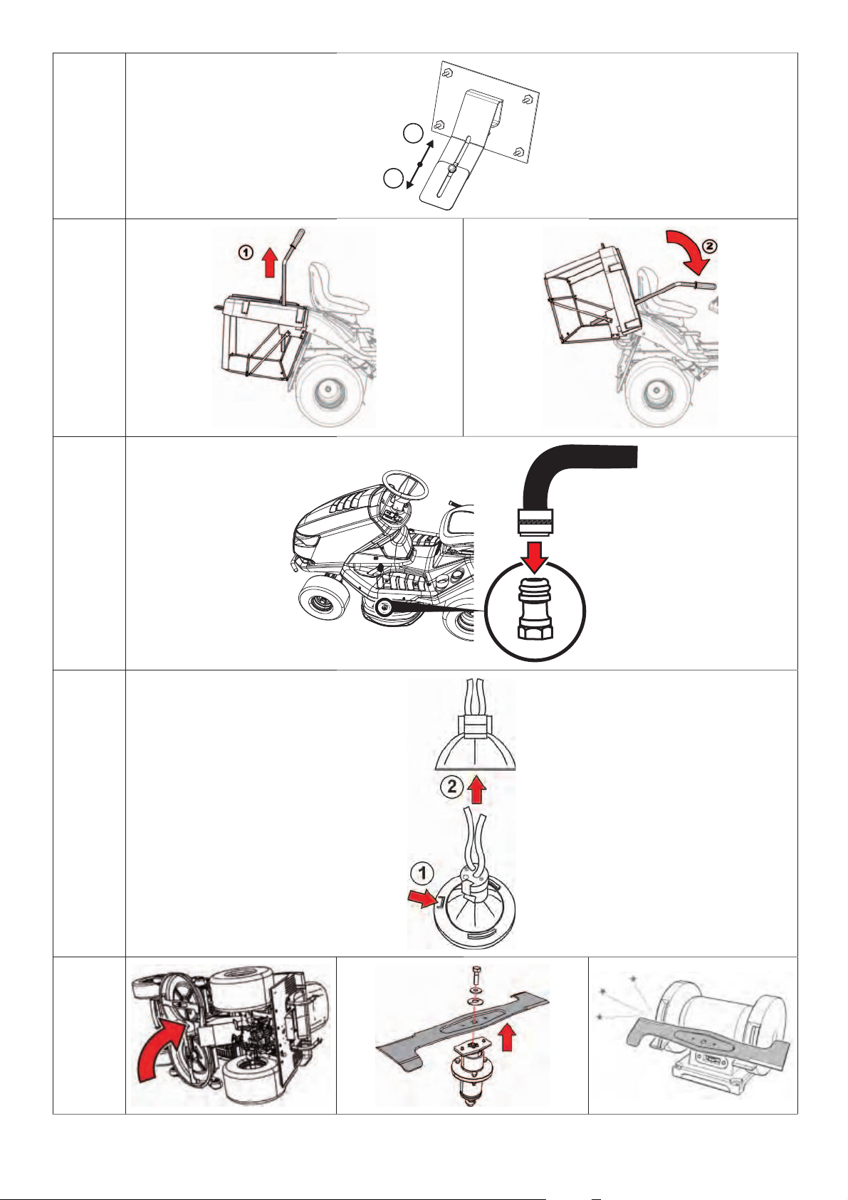
5.6 EMPTYING THE GRASS CATCHER
The grass catc her f ill level is signalled by the basket fill lid. The basket fill can be r egulated
using the sliding parts of the lid (lengthening or shortening of the arm).
(1) Sliding part pulled out = minimal basket fill
5.6a
(2) Sliding part pushed in = maximum basket fill
Emptying process:
Drive the machine to the place where you want to empty the grass catcher. Stop the machine and set
the brake. If it is on a slope, use the parking brake.
Shut off the mowing mechanism by pressing the switch downward.
If the machine has an AUT/MAN switch, leave it in the “AUT” position.
Set the accelerator lever to the “MIN” position.
On machines with hand-lifted and -tilted catchers:
Slide the catcher’s lif ting lever completely up (1) and by tilting it (2) empty the c atche r. Let
it empty freely, gradually loosen it and tilt it back.
On machines with mechanically lifted and tilted catchers:
5.6b
Press the c atcher ’s emptying switch to t he “LIFT” position and hold it down until the catcher has r isen
all the way. After the position is re ached, let up on the switch and wait for the c atche r to empt y. Then
press the switch b ack to the “S TART” position and hold it down until the catcher has tilted all the way.
After the position is reached, let up on the switch.
After tilting the catcher to the basic position, turn the mowing mechanism on using the lever switch.
40
Page 41

6. MAINTENANCE AND ADJUSTMENTS
Proper, regular maintenance and inspection of the machine helps extend the mower‘s life and problemfree oper ation. Worn-out or damaged parts mu st be replace d in a timely manner. Always use original
replacement par t s. Other r eplacement par t s can damage the machine and endange r the health of the
driver and other persons and void warranty claims. To order replacement par ts, always contact the
manufacturer or an authorized service facility.
6.1 OVERVIEW OF INSPECTION AND MAINTENACNE
INTERVAL
Regular maintenance Maintenance by hours of use Seasonal maintenance
Activity
Check the oil
(transmission,
engine)
Change the engine
oil
Fuel filter change
Battery
maintenance
(checking
electrolytes and
cleaning)
Inspect and adjust
the drive belt
Check the brake
control
Inspect tyre
pressure
Check cable
connections (loose
connectors)
Clean the mowing
mechanism
Check screw
connections
Check tension of
toothed belt that
rotates the blades
Check the V-belt
tension on the
mowing mechanism
drive
Check and adjust
play of front axle
and steering
Check operation of
safety switches and
devices
Check and adjust
engine operation,
transmission and
electromagnetic
connectors
Check and maintain
air filter, spark
plugs, and change if
necessary
Check mowing
mechanism (play,
shaft alignment,
inspect and sharpen
blades)
Notes to chart:
1 = Change the oil more often if the lawn mower has worked with a higher load or in outdoor temperatures of 35°C or higher.
2 = Check more often if the machine operates in a dusty environment.
3 = Check more often if the machine works in a sandy environment.
4 = Check more often if the a new belt has been installed.
Before
each use
4
After the
first 2
hours
After the
first 5
hours
After each
use
Monthly 25 50 100
1,2
4
4
1,2
3
Before
mowing
season
After
mowing
season
(storing the
machine)
41
Page 42

6.2 DAILY INSPECTION AND MAINTENANCE
- Before beginning any maintenance or service, familiarize yourself again with all instructions,
restrictions and recommendations in this manual.
- Always remove the key from the ignition and disconnect the spark plug cables before
performing any cleaning, maintenance or repairs.
- When working, always wear appropriate work clothes and shoes. When handling the cutting
blades or during activities that pose a cutting risk, wear appropriate work gloves.
- Avoid spilling fuel, oil or other hazardous substances.
Dispose of used oil, fuel or other hazardous substances according to applicable environmental
protection laws.
6.2.1 BEFORE STARTING WORK
TYRE PRESSURE INSPECTION
Inspect the t yre pressure regularly and make sure it meets requirements. Maintaining the specif ied
pressure is important to even mowing. Other pressure values can hamper driving and even result in loss
of control.
The air pressure in the front and rear tyres must be within the range of 80 - 140 kPa, and the difference
between the individual tyres can be ± 10 KPa.
CONTROL OF ENGINE OIL LEVEL
Place the lawn mower mower on a level surface. Open the bonnet and unscrew the cap of the filling port.
Unscrew the dipstick, wipe it clean, reinsert it and screw it back in. Then unscrew it again and read the
oil level.
The oil level must be between the t wo marks on the dipstic k. If it is not, add motor oil until it reaches
the “FULL” mark.
Further information on checking and adding oil is given in a separate manual provided by the
engine manufacturer.
CHECKING CABLES AND SCREW CONNECTIONS
Visually inspect the state of the cables and manually check tightness of screw connections.
CHECKING BRAKE FUNCTION
Check the brakes for proper operation. Proceed as follows:
Set the machine on a level surface and shut off the engine.
Press the brake pedal and engage the parking brake.
Use the bypass lever to cut off power to the rear wheels.
Try to pus h the machine for war d manually. If the rear whee ls turn, brake ser vice is ne eded. Cont ac t
an authorized service facility that will adjust them.
6.2.2 AFTER FINISHING WORK
MACHINE SETTINGS
After mowing, raise the mowing mechanism to the highest position and shut off power to the rear wheels.
Turn off the ignition, pres s the brake pedal and us e the park ing brake to keep the machine in position.
On machines with BS15 (15.5-hp) engines, close the fuel intake.
CLEANING THE MACHINE
Remove all dirt and clippings from the tractor’s surface, the removal tube and the mowing mechanism.
Thoroughly clean the gras s catcher ’s fabric bag. If grass is stuck to it, the mac hine can’t fill the gras s
catcher as well.
WASHING THE MACHINE
Before washing, park the machine on an appropriate level surface.
42
Page 43

Grass catcher:
- remove the grass catcher from the machine, wash it and let it dry.
Plastic parts:
- clean with a sponge and soapy water.
Mowing mechanism:
- wash from inside, including internal parts and removal tube.
- slip a hose of an appropr iate diameter onto the mechanism’s cover extension. St ar t the
engine, start the mowing mechanism and rinse the mowing mechanism for 10 minutes.
6.2.2
This rinse must be performed after every mowing.
Avoid washing with water near electrical equipment on the instrument panel, battery, etc.
6.3. REGULAR INSPECTION, MAINTENANCE AND ADJUSTMENTS
6.3.1 BATTERY
Correc t, r egular maintenance incr ease s the life of the bat te r y. You should therefore c heck it ac cor ding
to the battery manufacturer’s instruction manual.
Keep the battery contacts clean. If they get dirty or corroded, clean them according to the manufacturer’s
instructions. Interruption of the circuit caused by the oxidation of the contacts may lead to the
malfunction of the recharging function of the motor!
Regularly check the electrolytes. The level should be between the MIN and
MAX marks. For filling the electrolytes, use only distilled water.
A drained battery must be charged as soon as possible. Otherwise the cells may be irreversibly
damaged.
The battery must always be charged before:
- first use
- during a long storage period
- before operation after a long storage period
If the battery needs to be changed, always use a battery of the same size and model.
Further information on c heck ing and maintaining the batter y is given in a separate manual
provided by its manufacturer.
6.3.2 ENGINE
CHANGING THE OIL
Before changing the oil, prepare a container of at least 2 litres. For all
oil to drain from the engine, we recommend tilting the machine (such
as with wooden blocks) on the opposite side from the drain plug. Drain
the oil while it is still warm.
Remove the oil filler cap so that the oil will drain better and faster.
Unscrew the drain plug and let the oil drain completely into the
prepared container.
Screw the drain plug back in, pour in the right amount of the specified
oil ( Engine operation manual) and close the oil filler cap.
Use the dipstick to chec k the oil level. If necessar y, add oil to the
proper level.
43
Page 44

Further details on c hecking and adding oil, including information on the t ype and amount of
oil, are given in a separate manual provided by the engine manufacturer.
- If you come into contact with used oil, we recommend thoroughly washing your hands with
soap and water.
- Dispose of used oil according to environmental protection rules. Properly transport the oil in
a closed container to a used oil collection point. Never discard used oil with ordinary refuse,
and do not pour it down the sewer, into garbage or into the earth.
AIR FILTER MAINTENANCE
Never let the engine run without the air filter. This will wear out the engine quickly.
Maintain the air filter according to the instructions given in the manual provided by the
engine manufacturer.
SPARK PLUG MAINTENANCE
For perfect engine operation, the spark plug must be correctly installed and cleaned of deposits.
- Always use only the plug specified by the engine manufacturer!
- If the engine has been running shortly before inspec tion and re placeme nt, the spark plug
is very hot. Be careful not to burn yourself.
Disconnect the spark plug cable and remove the plug with a spark plug
wrench.
Visually check the appearance of the plug. If the plug is visibly very worn or
has a broken or scaled insulator, it must be replaced.
If the plug is soiled or just mildly worn, it must be carefully cleaned with an
appropriate (copper) wire brush.
Use a gauge to set the spark plug gap ( Engine operation manual).
After maintenance or replacement, properly tighten the plug. An improperly
tightened plug gets very hot and can cause serious engine damage.
Inspect, maintain and replace the spark plug according to the instructions given in the
manual provided by the engine manufacturer.
CHANGING THE FUEL FILTER
Never let the engine run without the air filter. This will wear out the engine quickly.
Change the fuel filter according to the instructions given in the manual provided by the
engine manufacturer.
6.3.3 REPLACING LIGHT BULBS
Light bulbs are seated in a bayonet catch and are accessible after lifting the hood.
Type of light bulb used:
Halogen light bulb MR16 12V / 20W GU5.3
When replacing the haloge n light bulbs fir st pres s the tab (1) and slide the bulb out of
the socket (2). For installation proceed in the reverse sequence.
When replacing a light bulb, always use the same type of light bulb or an equivalent
recommended by the light bulb vendor!
6.3.3a
44
Page 45

6.3.4 REPLACING FUSES
If a fuse fails, the engine will immediately quit, the mowing mechanism will stop, and all gauges on the
instrument panel will go dark. In that case, it is necessary to seek out the blown fuse and replace it with
a new one. Never replace a faulty fuse with one of a higher current rating!
The fuses are located on the steering column and can be accessed by lifting the cover and removing the
protective fuse cover.
Remove the fuse and insert a new fus e of the s ame rating as the or iginal one, i.e., 15A or 5A. If the
engine or the mowing mechanism cannot be st ar ted after fuse r eplacem ent, cont ac t your authorized
service centre.
Some models of machines are e quipped with a central electric al installation distribution box. Never
tamper with this distribution box, except to change fuses.
6.3.5. RAISING THE MACHINE
If you want to raise the lawn mower, use a jack and supports.
Proceed as follows:
Place the jack under the transmission on the rear axle and raise the machine’s rear end.
Insert two supports under the ends of the axle inside the rear wheels.
Lift the front end of the machine and insert two supports under each end of the front wheel pins.
Never tilt the machine to the side where the engine’s carburettor is located. This could make
oil seep into the air filter!
6.3.6 MOWING MECHANISM - SHARPENING AND CHANGING BLADES
SHARPENING BLADES
The cutting blades must be sharp, statically balanced and straight. Blunt, improperly sharpened or
damaged blades uproot grass, damage the lawn and don’t allow the catcher to collect grass properly.
- Never repair a deformed or otherwise damaged blade. Always replace it
immediately.
- Whenever handling the blades, wear solid work gloves.
Sharpening process:
Remove the grass catcher, tilt the machine to the right side, and place appropriate pads
under it. We recommend having another person help, in order to avoid in jury and damage
to the machine.
Unbolt both blades and clean them.
First sharpen the blades with a grinder, and then with a file.
Do not sharpen the blades directly on the mowing mechanism.
After sharpening, do not reinstall the blades yet, but check their balance. See the procedure below.
Before r einstalling the blades, chec k the shear pins that protec t the mowing mechanism
from damage. If the shear pins are damaged, replace them immediately . Replacement pins
come with the machine.
6.3.6a
6.3.6b
After c hecking the balance and the sh ear pins, bolt the blades back on. When installing, make sure
the blades to not face upward inside the mowing mechanism cover. Do not switch the left one with the
right one. The right blade has leftward threads.
Carefully tighten the blades’ mounting bolts using a torque wrench set to ±3 Nm. This torque is
reached at exactly the moment when the tangential spring under a blade’s mounting bolt is completely
compressed. After that, do not tighten the screw further.
45
Page 46

BALANCING THE BLADES
Use great care when aligning and balancing the blades. Vibration from misaligned and unbalanced
blades can damage the engine or mowing mechanism.
When balancing, insert a s crewdriver into the ce ntring hole
and place the blade in horizontal position. If the blade stays
in this position, it is balanced. If one of the ends of the blade
is heavier, grind this side until it is balanced. When grinding
for balance, do not shor ten the blade! The maximum static
balance is 2 g.
If you are not sure of the procedure, contact your authorized service centre, where they will
gladly advise you.
REPLACING BLADES
If the blades have been damaged by frequent use, they cannot be proper ly sharpened and must be
replaced. Proceed as follows:
Remove the grass catcher, tilt the machine to the right side, and place appropriate pads unde r it. We
recommend having another person help, in order to avoid injury and damage to the machine.
Unbolt both blades.
Before installing the new blades, check the shear pins that protect the mowing mechanism from
damage. If the shear pins are damaged, replace them immediately.
Check the new blades’ balance. See above.
Bolt the new blades on. When installing, make sure the blades do not face upward inside the mowing
mechanism cover. Do not switch the left one with the right one. The right blade has leftward threads.
Carefully tighten the blades’ mounting bolts using a torque wrench set to ±3 Nm. This torque is
reached at exactly the moment when the tangential spring under a blade’s mounting bolt is completely
compressed. After that, do not tighten the screw further.
- As soon as the blades meet a hard object, stop the engine immediately and check
them! The shear pins may be damaged or severed.
- Whenever handling the blades, wear solid work gloves.
6.3.7 MOWING MECHANISM - INSPECTION AND BALANCING
To achieve the best mowing results the mowing deck mu st be set at the correc t mowing
height and both sides of the deck must be level. Therefore, regularly check the distances A,
B and C.
Distance A is the front e dge of the mowing deck in the travel direction and it should be
23-25 mm above the ground.
Distance B is the rear edge of the mowing deck in the travel direction and it should be
28 -32 mm above the ground, i .e. the rear edge must be 5-8 mm higher than the front edge.
Distance C represents the se tting of the mowing deck in the side direction and the distance
between the left and right side should not be more than 5 mm.
Prior to starting adjustment, place the machine on an opt imally even surface, inflate all
the tyres t o the prescribed pre ssure (80 -140 K pa, ± 10 Kpa difference be tween the
individual tyres) and secure the entire machine against movement ( e. g using a suitable
wedge, etc.).
6.3.7a
Release the safety pins on the mowing deck cover on the right side by sliding a screwdriver
into the groove of the pin and turning it anticlockwise. Take the cover off the machine.
Unscrew t wo nuts and washer from the drive belt ten sioning mechanism on the mowing
deck. This will release the spring and the belt. Remove the belt from the pulley wheels.
46
6.3.7b
6.3.7c
Page 47

Unscrew t wo nuts and washer from the drive belt ten sioning mechanism on the mowing
deck. This will release the spring and the belt. Remove the belt from the pulley wheels.
Set the correct distances A, B and C by adjusting the bolts in the front and rear part of the
6.3.7d
mowing deck.
When adjusting distance C it is recomme nded to place something under both sides of the
mowing deck cover, use underlays of the same si z e (e.g. wooden boards, etc.) and use them
to level the deck so that the distance from the ground is the same on both the left and right
hand side.
After setting the correct distances of the mowing deck, pull tight all loose nuts and bolts using a torque
of 55 - 65 Nm. After putting on the mowing deck drive belt and the tensioning mechanism, tighten the
nuts so that the length of the tensioni ng s pring is 85 ± 1 mm. Then reattach the mowing mechanism
cover.
If you are not certain about this procedure, have it performed by a service centre.
6.3.8 MOWING DECK - CHECKING AND ADJUSTING THE BELT
Because of the demands placed on it, the tension of mowing deck belt drive declines over time and it is
necessary to tension it. The belt is tensioned using a tensioning mechanism with a spring and is correctly
tensioned at the moment when 4 kPa of force is applied at the mid-distance between the pulley wheels,
and the belt bends out by approximately 0.5 cm.
T o measure force you can use a standard mechanical dynamometer available in stores selling
such products.
Release the safety pins on the mowing deck cover on the right side by sliding a screwdriver
into the groove of the pin and turning it anticlockwise. Take the cover off the machine.
Tighten the tensioning bolt nut so that the length of the tensioning spring is 85 ± 1 mm.
Reattach the mowing mechanism cover.
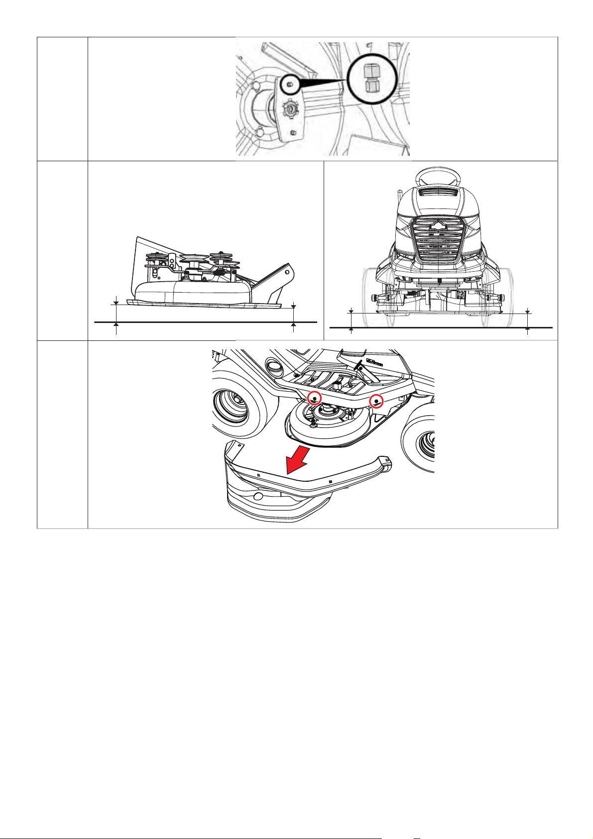
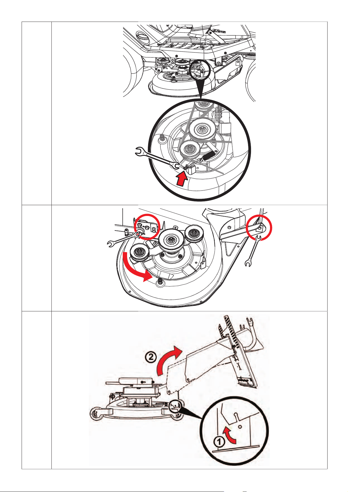
6.3.9 MOWING MECHANISM - REMOVAL
Set the mowing mechanism to the lowest position by setting the adjustment lever to position 1.
Take off the mowing deck cover ( 6.3.7 and 6.3.7b).
Slightly raise the grass removal tube (1) and slide it off the two pins welded to the f rame
of the mowing mechanism. Then either slide the tube 10 cm to the re ar (2) and secure it,
or completely remove it from the machine through the rear plate.
Unscrew t wo nuts and washer from the drive belt ten sioning mechanism on the mowing
deck. This will release the spring and the belt. Remove the belt from the pulley wheels.
Turn the pulley wheel assembly s o t hat you get acc e ss to the bolts on the rear side of the
mowing deck. Unscrew the bolts.
6.3.7b
6.3.7c
6.3.9a
6.3.7c
6.3.7d
It is not necessary to remove the bolts on the front side of t he mowing deck, it is en ough
to unhook the deck from the holding bracket.
Slowly pull the mowing deck out of the machine.
47
6.3.9b
6.3.9c
Page 48

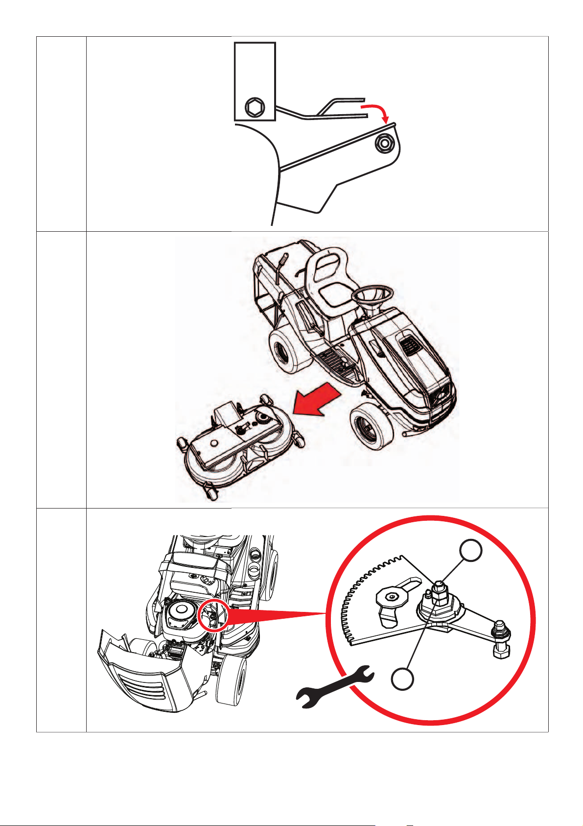
6.3.10 STEERING MAINTENANCE
Regularly check to see that there is no excessive play between the steering rack and pinion.
If there is too much play, reduce it.
Ignoring this maintenance can cause damage to the steering.
How to adjust the play:
Open the hood of the machine.
Loosen the two M12 nuts (1) on the eccentric bolt.
On the hexagonal eccentr ic (2) place an appropriate wrench and turn it until the the play
6.3.10
is reduced to the minimum.
Tighten both M12 nuts (1) to 35 - 45 Nm.
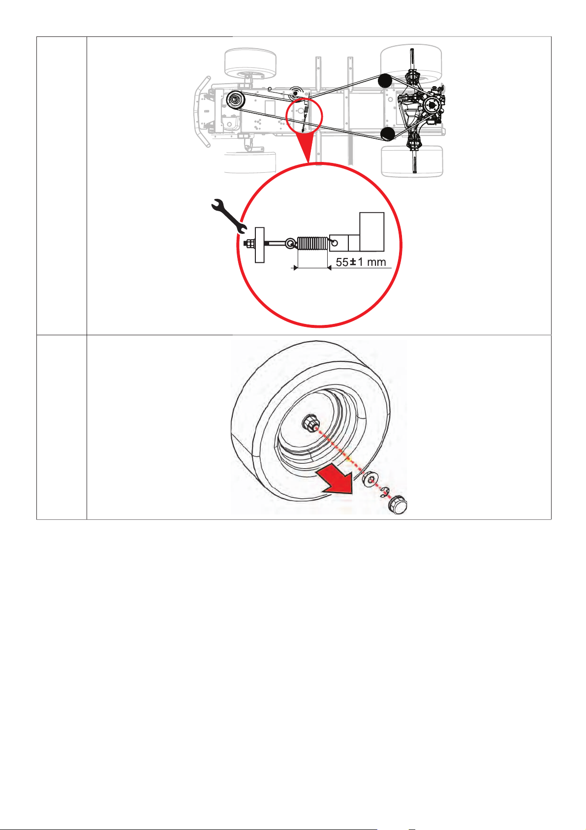
6.3.11 CHECKING AND ADJUSTING THE DRIVE BELT
Regularly check the c ondition and tension of the travel drive belt. As s oon as the belt start s to slip
through or even produce an odour, it is necessary to tension or replace it.
Take off the mowing deck cover ( 6.3.7 and 6.3.7b).
By tightening the nuts on the bolt, set the spring to a length of 55 ± 1 mm.
6.3.11
Do not over-tension t he belt ab ove this level, this will reduc e it s lifetime and may
also cause damage to the transmission!
Reattach the mowing mechanism cover.
6.3.12 BELT REPLACEMENT
Replacing the drive belt is a relatively demanding proc edure and must be entru sted to an authorized
service facility.
6.3.13 REPLACING WHEELS
Before changing one of the wheels, park the tr actor on a solid, level surface, shut off the engine and
remove the key from the ignition. Change the wheel as follows:
Raise the machine using an appropriate jack on the side on which the wheel is to be
changed. Set the jack below a solid par t of the machine’s frame or on the transmis sion
arm. Secure the machine below with an appropriate wooden block.
Remove the protective cover from the wheel (front wheels only).
Use an appropriate screwdriver to remove the retaining ring and remove the washer.
Take the wheel off the shaft. For rear wheels there is a spring on the shaft.
When putting the wheel b ack on, perform the ass embly steps in reverse order. Before installing the
wheel, clean all parts, and lightly grease the shaft. Especially for wheels on the rear axle, this greasing
is indispens able for later whee l removal. If the s haft is no t grease d, later a ssembly may be
difficult.
6.3.13
When installing a rear wheel, be careful of the mutual position of the spring on the shaft and the groove
in the wheel.
6.3.14 REPAIRING TYRE DEFECTS
The machine is equipped with tubeless tyres. If they are defective, entrust their repair to a professional
tyre service or to an authorized Seco lawn mower service centre.
48
Page 49

6.3.15 MAINTAINING THE HYDROSTATIC TRANSMISSION
T o ensure reliable operation of the transmission, you must main tain the proper oil level. The transmission
filling ports are accessible after removal of the machine’s removal tube ( 6.3.9). The prescribed
values are included in the manual of the manufacturer that supplied the machine part.
If there are problems with the transmission, get immediate help from an authorized service
centre to prevent serious damage.
6.3.16 OVERVIEW OF BOLT TORQUE
Mowing mechanism: Torque
Central blade bolt 30 ± 3 Nm
M12 nuts for the mowing mechanism drive pulleys 45 - 55 Nm
Steering:
M8x30 bolt to the steering section 15 - 25 Nm
M12 bolt to the steering section 45 - 55 Nm
Engine:
Bolt to the electromagnetic connector 60 - 70 Nm
Bracket screw for the drive belt tension pulley 25 - 35 Nm
Self-locking nuts must be replaced with new ones during removal and reinstallation.
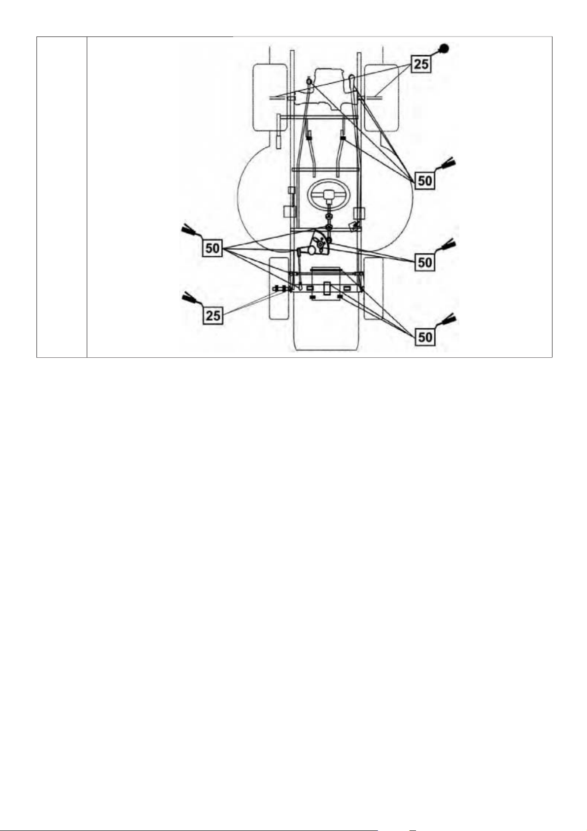
6.4 LUBRICATION
Lubricate the machine according to the following schedule.
The bearings of the tensioning pulleys, guide pulleys and mowing mechanism are self-lubricating.
Before s toring the machine for an extende d time, thoroughly lubr icate all areas shown in the schedule.
But particularly the half-axles of the front and rear axles (it is necessary to disassemble the rear
wheels).
Symbol Explanation
Grease
6.4
SAE 30 oil
Interval in
hours
Apply grease to:
angle joints of the drive connecting rods - remove and lubricate
brake rod bolt - lubricate the rod near the bolt hole
bolt to the mowing mechanism lift rod - lubricate the rod in the area of the bolt hole
angle joints of the steering connecting rods - remove and lubricate
angle joints of the wheel pins - remove and lubricate
49
Page 50

front wheel bearings
wheel pins that go through the axle
centre rotary pin of the front axle - through the grease nipple
steering wheel shaft bearing - lubricate
toothed steering segment and eccentric - lubricate
spigots of the wheels of the front axle for the front wheel
rear half-axles for the rear wheel
Use oil to lubricate the rotating points:
brake pedal
50
Page 51

7. TROUBLESHOOTING
Never perform a service operation if you do not hav e the appropriate qualifications and equipment. The
operations below can be pe rforme d by the user. Service op erations other than those shown here will
void the warranty when pe rforme d by the user. The manufactur er is not liable for damages resulting
from the user’s poor execution of prohibited service operations.
Problem Solution
Remove clogged clippings from the underside of the mowing mechanism.
Make sure the blades are sharp and not deformed.
The machine cuts
unevenly
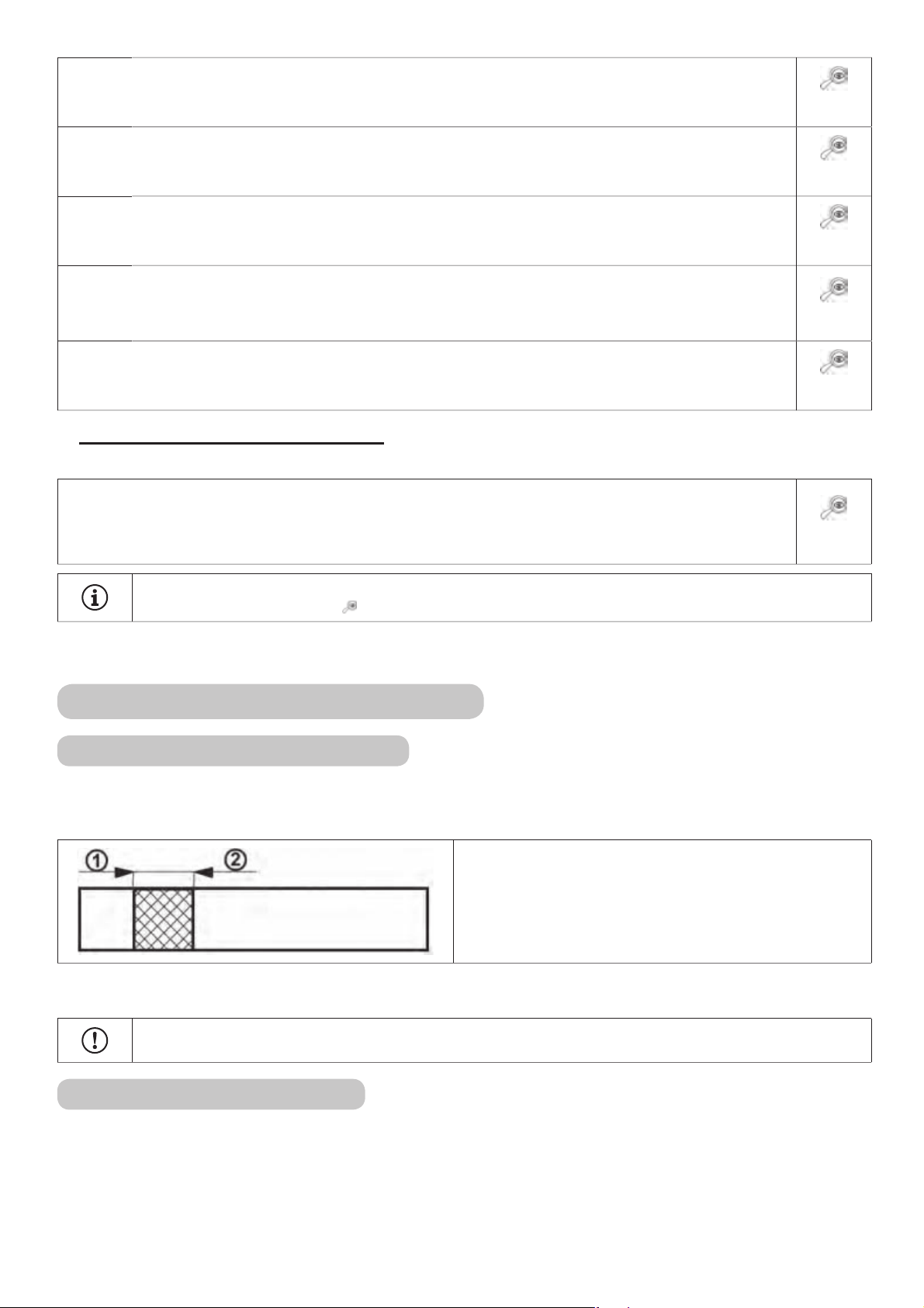
A strip remains
unmowed between the
blade rotors
The mowing
mechanism pulls the
turf
The mowing
mechanism does not
eject the grass
Check the blade tightness.
Check the mowing mechanism’s height adjustment. (
Check the tension of the belts ( 6.3.8). If necessary, adjust the tension.
Check the blade shaft. If it is damaged or overly worn, replace it.
Check f or damaged bearin gs. Repair or replac e, if necessa ry. When mowing thick grass o r
grass with an excessively wet surface, an unmowed strip may remain.The driving speed should
corr espon d to the ri ght trans missio n gear fo r the mowing co ndition s. The en gine should r un
with a completely open throttle.
Make sure the blades are sharp and not deformed. Replace the blades, if necessary.
Check the tension of the belts (
Check for damaged bearings. Repair or replace, if necessary.
Check the mowing height and adjust it, if necessary. Turf is often pulled on uneven terrain.
Check to see if the blades are warped. Replace the blades, if necessary.
Remove clogged clippings from the underside of the mowing mechanism. Under wet conditions,
the removal tube and the underside of the mowing mechanism’s exit port can be clogged with
grass. Do not cut wet grass.
The driving speed should correspond to the right transmission gear for the mowing conditions.
The engine sh ould run with a comp letely open th rottle. Whe n mowing tall grass, f irst mow
once at a high adjustment and then again at normal height. Abide by the information in chapter
5.5.3.
Check the tension of the belts (
Especially after replacing blades, make sure that the blade is installed correctly.
6.3.8). If necessary, adjust the tension.
6.3.8). If necessary, adjust the tension.
6.3.7). If it is not correct, readjust it.
The mowing
mechanism’s drive belt
stops during operation
The mowing
mechanism’s drive belt
slips
The mowing
mechanism’s drive belt
wears excessively
Set the blades in
motion
The mowing mechanism’s drive belt may be damaged if it jumps out of the pulley during
operation. If the belt still jumps out after trying the following steps, it must be replaced.
Check the belt tension (
Check the belt guide.
Check the mowing height, and adjust it if necessary.
Check to see if belt movement is being impeded by a foreign object. If it is, remove the object.
Double check all pulleys. A bent or broken pulley can cause problems. Replace it, if necessary.
Check th e inner sur face of the pull ey on the engine. If it is r ough or has cr acks, the pull ey
should be replaced.
Check for worn-out parts in the tensioning mechanism, and replace them if necessary.
If the grass is too tall or wet, the mowing mechanism’s belt can slip. Check to see if the belt is
worn out. If it is, change it.
Check the belt tension (
Check th e te ns io n sp r ing o f th e turnbuckle me c ha nis m of t he m owing be l t.Re pla c e th e pull ed
or damaged spring.
Check all ar eas of the pulley guide. Ch eck to see if belt m ovement is being impede d by a
foreign object. If it is, remove the object.
Check the pulleys, and if they are damaged, replace them.
Check the mowing height, and adjust it if necessary.
Check the belt tension (
Check to see if the belt is worn out or damaged. If it is, replace it. If it is loose, tighten it.
Check the spring on the tensioning mechanism. Replace the broken or damaged spring.
Check to see if belt movement is being impeded by a foreign object. If it is, remove the object.
6.3.8). If necessary, adjust the tension.
6.3.8). If necessary, adjust the tension.
6.3.8). If necessary, adjust the tension.
The blades stop late
Check t he belt tension (
tightened further due to considerable wear, replace it.
Check to see if belt movement is being impeded by a foreign object. If it is, remove the object.
Check the operation of the electromagnetic connector to see if it shuts off properly. If it
malfunctions, have it repaired or replaced by an authorized service facility.
6.3.8). If necessar y, adjust the te nsion. If the belt ca nnot be
51
Page 52

Problem Solution
When the mowing
mechanism’s drive
is turned on, the
belt shows extreme
vibration
Check the blades to see if they are uneven or war ped, and also check to see if they are
balanced. If they are deformed, replace them.
Check to see if the belt has burnt surfaces or irregularities that may lead to vibration. Replace
the damaged belt.
Check to see if the blades are worn or damaged. Replace them, if necessary.
Check the operation of the electromagnetic connector to see if it turns on properly. If it
malfunctions, have it repaired or replaced by an authorized service facility.
Check th e inner sur face of the pull ey on the engine. If it is r ough or has cr acks, the pull ey
should be replaced.
Check to see that no grass is lodged under the mowing mechanism. If there is any, remove it.
Check t o make sure th ere i s no defe ct in t he engin e mount. If ne ces sar y, tighten or re place
the bolts.
Check the belt tension (
6.3.8). If necessary, adjust the tension.
The driving belt is
sliding.
The drive belt squeaks.
The drive belt jumps
out during operation
The machine does
not move when the
accelerator is pressed
There is a lot of
vibration while driving
The steering slips or is
loose.
The engine doesn’t run
Check the drive belt tension (
Check to see if the belt is damaged or worn.
Check to s ee if th e drive coup ling mec hanism is b locked by a f ore ign objec t. If it is, r emove
the object.
Check to see if the engine or transmission pulley is damaged. If necessary, replace it.
Check th e drive belt ten sion (
belt tension. If the brake operation is not in order, have an authorized service centre adjust it.
Check the drive belt tension (
Check the belt guide. If necessary, adjust it.
Check for damaged pulleys. Replace them, if necessary.
Check th e s p a c e between the drive coupling mec h ani s m. If there are deviatio n s, th e coupling
pulley support may be bent. Replace it if necessary.
Check the drive belt tension (
Check the engine and transmission pulleys for sheared or cut grooves. Replace if necessary.
Check for damaged or deformed pulleys. Replace them, if necessary.
Check to see if the drive belt has burnt areas or other irregularities. Replace it, if necessary.
Check the drive belt tension (
Check the balance of the mowing blades. Replace or rebalance them, if necessary.
Check to see if there is too much play between the segment and the pinion. If there is, adjust
the toothed segment. Check for wear to the ball joints. If necessary, replace the joints.
Check to see if there is fuel in the tank.
Check to see if the designated engine start-up procedure has been followed (
Check the fuse. If necessary, replace it.
Check to see that the battery’s pole voltage is 12 V. On a new machine, make sure the battery
has been ac tivate d and char ged. On new mac hines, remove th e spark plu gs and make sure
that the oil hasn’t accumulated in the cylinder due to improper handling.
Check to see that all wire connectors are in order and that the electrical system’s switches are
operational.
Test the engine exactly according to its manufacturer’s user manual. Have the machine’s
electrical system tested at a professional workshop.
6.3.11). If necessary, adjust the tension.
6.3.11) and the brake operat ion. If necess ary, adjust the
6.3.11). If necessary, adjust the tension.
6.3.11). If necessary, adjust the tension.
6.3.11). If necessary, adjust the tension.
5.2)
Engine turns but won’t
fire
The machine can’t be
pushed, or only with
difficulty
There is a whistling
sound while driving
Check to s ee i f the de si gnate d engin e st art-up procedure ha s be en f ollowe d (
to see if the fuel in the tank is clean.
Check to see if the fuel filter is clogged.
Check to see if the fuel cap is open (only on BS15.5 engines).
Make sure that the fuel lever is in the “STARTER” position.
Test the engine exactly according to its manufacturer’s user manual. Have the machine’s
wiring and switches tested at a professional workshop.
Check to make sure the bypass lever is in the “0” position.
Check th e belts, and t he guide and ten sioning pulleys. If the p roblems p ersis t, seek out an
authorized service centre.
5.2). Check
52
Page 53

7.1 ORDERING REPLACEMENT PARTS
We recommend using original replacement parts, which guarantee safety and interchangeability. Always
order replacement parts through an authorized dealer or service organization that is informed about the
current technical changes to the products during production.
For fast, precis e identification of the r eplacement par t you need, always include the serial number on
the order form. You will find this number on inside cover of this publication. Also include the production
year, which is on the manufacturer’s label below the driver seat.
7.2 WARRANTY
The warranty requirements are described on the warranty card, which is supplied with your machine at
the dealer.
53
Page 54

8. END-OF-SEASON MAINTENANCE AND STORAGE
After th e end of the seas on or if you will not be using your machine for more than 30 days, prepar e it
for storage as so on as possible. If fuel r emains in the fuel tank for mor e than 30 days, it may form a
sticky sediment, which may hurt the carburettor and cause poor engine performance. Therefore empty
the fuel tank.
- Never store the lawn mower with a full tank of fuel inside a building or in a
poorly ventilated area, where there are fuel fumes, open flame, sparks or ignition
sources, a furnace, central heating, dry rags, etc. Handle fuels and lubricants
carefully. They are highly flammable and careless handling can cause severe
burns or property damage.
- Empty the fuel take only into an approved container and outdoors away from open
flame.
Recommended procedure for preparing your machine for storage:
Thoroughly clean the entire machine, especially the interior of the mowing mechanism ( 6.2.2).
Do not clean using petrol. Use degreasing agents and warm water.
Repair and repaint chipped paint areas to prevent corrosion.
Remove and replace defective or worn-out parts and tighten all loose nuts and bolts.
Prepare the engine for storage according to the engine user manual.
Lubricate all lubrication points according to the lubrication plan ( 6.4).
Remove the battery, clean it, fill it with distilled water up to the lower portion of the circle in the filling
port, and completely charge it. A drained battery may freeze and burst. If necessary , store the battery
in a cool, dry space. Recharge the battery every 30 days and check its charge regularly.
Cover the mower with a cloth and store it in a clean, dry room.
The best way to keep your machine in top operating condition for next season is to have an
authorized service centre check and adjust it every year.
8.1 MACHINE BELTS
It is not necessary to loosen the belts when the machine is taken out of operation for an extended period
of time. When the machine is star ted up fo r use again, we strongly rec ommend th at you allow the
machine belts to run free for at least 5 minu tes. This will prevent vibrations and ensure that after
an extended period of inactivity the belts will align into the correct working position.
9. DISPOSING OF THE MACHINE
After the mac hine’s operational life is over, the owner is responsible for it s dispo sal. This may be done
in two ways:
a) Handing the machine ov er to a company that specializes in this work ( scrap yard, automotive junkyard,
secondary waste collection facility, etc.). Y ou w il l receive a proper receipt when handing the machine
over for disposal.
b) Disposing of the machine yourself. In that case we recommend following the procedure below:
Dispose of the product by recycling the secondary materials according to waste disposal laws.
Disassemble the entire machine.
Clean, pack and store all parts that can be reused.
Divide the remaining parts into those that are ecologically harmless and those that threaten the
environment, such as rubbe r parts (washers), lubricant residues on b e ar ings or ge ars. Ecologically
harmful components mu st be discarded ac cording to waste disposal laws applicable in the user ’s
country. For example, in the Czech Republic, it is waste disposal law No. 185/2001 Coll.
Separate discarded refuse according to the waste disposal catalogues in keeping with the applicable
decree. Ecologically friendly waste shall be treated as reusable material.
54
Page 55

10. ES STATEMENT OF COMPLIANCE
pursuant to: Council Directive No. 2006/42/EC (Government directive NV 176/2008 Coll.)
Council Directive No. 2004/108/EC (Government directive NV 616/2006 Coll.)
Council Directive No. 2000/14/EC (Government directive NV 9/2002 Coll.)
A. We: Seco GROUP a.s., Šaldova 408/30, Prague 8
branch 02 Jičín, Jungmannova 11
Corporate number: 60193450
issue the following statement:
B. Mechanical equipment
- name: Riding mower
- model : AJ 92
- serial number:
Description:
The A J 92 is a four-wheel self pr op elle d lawnmower with B rig gs & Str at t on mot or s 3130, 4155 a 7160. The
motor drive is tr ansf err ed t hrough an e lec tr omagne tic c lutch u sing V-belt s to the mowing m echani sm and
the drive trans mis si on. T he mowing m ec hani sm ha s two blades driven by a double -s ide d V-belt. T h e gr as s
clippings are guided through a chute to the grass catcher or directed to the ground with the deflector. I nstead
of collec tion the mower may perfor m mulching by blocking the ejec tion chute and using two additional
blades.
C. Legislation forming the basis for assessment of compliance:
ČSN EN ISO 836+A4, ČSN EN ISO 3767-1,2,3, ISO 11684, ČSN EN ISO 11201,
ČSN EN ISO 12 100-2, Council Directive No. 97/68/EC (2002/88/EC)
D. Assessment of compliance was performed according to the designated procedure in:
- Council Directive No. 2006/42/EC, Article 5, (eqv. §5, para. 2, NV No. 176/2008 Coll.)
- Council Directive No. 2004/108/EC, Article 7, (eqv. §4, para. 1, NV No. 616/2006 Coll.)
- Council Directive No. 2000/14/EC, Annex VIII,(eqv.annex 7, NV No.9/2002 Coll.)
under the supervision of a notified person from LRQA registration number 0088
71 Fenchurch street
London EC3M 4BS, United Kingdom
E. Entities participating in the assessment of compliance:
Authorised entity no. 255, Notified entity no. 1016
Státní zkušebna zemědělských, lesnických a potravinářských strojů a.s. (SZZPLS)
Třanovského 622/11, 163 04 Prague 8, Czech Republic
Final Report No. 33 257 and 31 768
F. We confirm that:
- this mechanical equipment defined above complies with the requirements in the above technical regulations
and under normal operating conditions it is s a f e.
- measure s have been taken to en sure the co mpliance of all pro duct s introduc ed to the mar ket with the
technical documentation and the requirements contained in technical regulations.
- guaranteed emission level of acoustic power L
Measured mean values of acoustic power A depending on the engine used:
ENGINE Speed (min-1) Measured level of acoustic power LWA [dB(A)]
Briggs & Stratton 3130 POWERBUILT 2700±100 100
Briggs & Stratton 4155 POWERBUILT 2700±100 100
Briggs & Stratton 7160 INTEK 2700±100 100
is 100 dB(A)
WA G
Technical documentat ion of the scope r equired by appendix V II to regulation 2006/42/EC and by appendix VIII
of regulation 2000/14/EC is kept by the manufacturer at the following address:
Seco GROUP a.s.
plant 02 Jičín
Jungmannova 11
506 48 Jičín
In Jičín on 1. 10. 2013 Bc. Bořek Kučera
Member of the Board of Directors
of the joint stock company
55
Page 56

Seco GROUP a.s. is dedicated to continuous development and improvement of all its machines. Therefore, this manual’s text and
illustrations may vary from the actual product. No claims can be deduc ed from this. Pri nt, duplication, publication or translation
(in whole or in part) is prohibited without the written consent of Seco GROUP a.s. The manufacturer reserves the right to change
technical parameters of the product, without prior customer notification.
56
Page 57

VORWORT
Sehr geehrte Kunden,
Danke für den Kauf eines Rasenmähers von der Seco Group AG. Seco ist auf allen Märkten in Europa als
Hersteller von hochqualitativen Rasenpflegemaschinen und Zubehör bekannt.
Dieses Handbuch enthält Anweisungen zur sicheren Einrichtung, Bedienung und Wartung Ihres
Rasenmähers.
Lesen Sie dieses Handbuc h sorgfältig durch. Be folgen Sie alle Anweisungen, die in diesem
Handbuch gegeben werden. Sie führe n Sie nicht nur durch die Bedienung Ihrer Maschine,
sondern helfen Ihnen auch seine optimale Anwendung und lange Lebens dauer zu sichern.
Benutzen Sie die Maschine nicht, wenn Sie nicht gründlich mit allen Anweisungen,
Einschränkungen und Empfehlungen, die in diesem Handbuch gegeben werden,
vertraut sind.
Heben Sie dieses Handbuc h für später auf. Das Handbuch muss als Teil des Rasenmähers
betrachtet werden und muss mit ihm mitgegeben werden, wenn er verkauft wird.
Wenn Sie irgendwelche Fragen haben oder Ihnen etwas unklar ist, scheuen Sie sich nicht, sich an eines
der mehr als 100 autorisierten, gut ausgestatteten Servicezentren in ganz Europa zu wenden. Über sie
erhalten Sie Zugang zu den im Werk ausgebildeten und geprüften Servicefachleuten.
Symbole, die in diesem Handbuch benutzt werden
SYMBOL BEDEUTUNG
Diese Symbole bedeuten „VORSICHT“ und „WARNUNG“ und weisen auf Faktoren hin, die
die Maschine beschädigen und/oder den Benutzer schwer verletzen könnten.
Dieses Symbol weist auf eine wichtige Anweisung, Eigenschaft, Praxis oder Angelegenheit
hin, die befolgt werden muss oder an die gedacht werden muss, wenn die Maschine
eingerichtet, benutzt und gewartet wird.
Dieses Symbol weist auf nützliche Informationen über die Maschine oder das Zubehör hin.
Dieses Symbol bezie ht sich auf die Abbildung im vorderen Teil des Handbuchs. Zu ihm
gehört immer die Abbildungsnummer.
Dieses Symbol bezieht sich auf ein anderes Kapitel dieses oder eines anderen Handbuchs.
Gewöhnlich gehört dazu die Nummer des Kapitels, auf das es sich bezieht.
57
Page 58

Verweise zu den Richtlinien
Linke und rechte Seiten Hintere und vordere Hälften
L = linke Seite, R = rechte Seite H = hintere Hälfte, V = vordere Hälfte
1. TECHNISCHE INFORMATIONEN
1.1 Anwendung
Das Gerät AJ92 CHALLENGE ist ein zweiachsiger Aufsitzmäher mit Eigenantrieb zum Mähen von
ebenen, gepf legten Rasenf lächen mit einer maximalen Wuchshöhe von 10 cm, z.B. in Parks,
Gärten und auf Sp ortplätzen, auch geeignet für Hänge mit leichte r Neigung, auf denen sich keine
Gegenstände befinden (herabgefallene Äste, Steine, feste Gegenstände usw. ). Der Neigungswinkel
darf 10° (17%) nicht übersteigen.
Jegliche Anwendung dieses selbstfahrenden Rasenmähers, die in diesem Handbuch
nicht erwähnt is t oder die den besc hriebenen Anwendungs bereich üb erschr eitet,
ist als eine Anwendung zu betr achten, die gegen den Zweck verstößt. Der Be nutzer
trägt die ausschließliche Verantwortung für all solche Benutzungen, und der Hersteller
ist nicht für Schäden verant wortlich, die daraus resultieren. Der B enutzer ist auch für die
Einhaltung der Bedingungen verantwor tlic h, die vom Hersteller f ür die Bedie nung, Wartung
und Reparatur dieser Maschine, die nur von Personen benutzt, gewartet und repariert
werden darf, die mit ihr vertraut sind und über die Sicherheit unterwiesen worden
sind, vorgeschrieben wurden.
Es darf nur vom Hersteller gene hmigtes Zubehör an der Masc hine angebracht wer den.
Bei Verwendung von nicht genehmigtem Zubehör erlischt sofort die Garantie.
1.2 HAUPTTEILE DES RASENMÄHERS
Der Aufsitzmäher AJ92 besteht aus folgenden Grundeinheiten:
1.2
(1) Rahmen und Stoßstange
Der Rahmen und die Stoßstange tragen die meisten Hauptteile der Maschine.
(2) Vorderachse und Räder einschließlich Lenkmechanismus
Die Vorderachse erlaubt die Räder zu steuern. Die Lenkung erfolgt über das Lenkrad.
(3) Mähmechanismus
Das Mähwerk mäht und sammelt das Gras. E s be f indet s ich unte r der Mas c hine. Es be st eht
aus Abdeckung, Hauptplatte und zwei Mähmessern.
(4) Grasabsaugrohr
Es verbindet das Mähwerk mit der Grasfangvorrichtung. Hierdurch wird das Gras in die
Grasfangvorrichtung weitergeleitet.
58
Page 59

(5) Getriebekasten und Hinterradantrieb
Der Getrieb ekast en und das hydrost atisc he Get rieb e sind zum Umsc halten der Gänge be im
Fahren.
(6) Leerlauf
Der Leerlaufhebel dient zum Ein- und Auskuppeln der Kraft vom Getriebekasten auf die
Hinterräder. Er befindet sich in der Nähe des linken Hinterrads und ist je nach Bauweise der
Maschine vor oder hinter dem Rad.
(7) Grasauffänger
Der Grasauffänger befindet sich am Hinterteil der Maschine und besteht aus einem
1.2
Stahlrohrrahmen, einem Stoffbeutel und einem Entleerhebel.
(8) Fahrerbereich
Der komfortable Sitz erlaubt den Zugang zu allen Bedienelementen der Maschine.
(9) Motorhaube, Motor, Verkabelung und Akku
Die Motorhaube besteht aus Kunststoff-und Metallabdeckungen, die die elektrischen und
mechanischen Teile der Maschine entsprechend abde cken. Unter der Motorhaube befindet
sich ein Viertaktdieselmotor, der am Rahmen befestigt ist. Die Batterie befindet sich in dem
Aufbewahrungsbereich unter dem Lenkrad.
1.3 TYPENSCHILD UND ANDERE SCHILDER AN DER MASCHINE
1.3.1 TYPENSCHILD
Jeder selbst fahre nde Rasenmäher is t durch das Typenschild des Her steller s gekennzeichnet, das sich
unter dem Sitz befindet. Sie erhalten Zugang zu ihm, indem Sie den Sitz anheben.
1. Rasenmähermodell
2. Motormodell
3. Baujahr
4. Gewicht
5. Name und Adresse des Herstellers
1.3.1
6. EC-Produktkonformitätsbestimmungen
7. Produktkonformitätssymbol
8. Logo des Herstellers
9. Garantierte Lautstärke nach Richtlinie 2000/14/EC
Der Verkäufer schreibt die Seriennummer Ihrer Maschine auf den Rückumschlag dieses
Handbuchs.
59
Page 60

1.3.2 WEITERE SCHILDER UND IHRE BEDEUTUNG
Folgende Etiketten und Aufkleber sind an Ihrer Maschine angebracht:
Schilder links und rechts am Mähwerk:
Nicht
betreten
Garantierter
Geräuschpegel
1.3.2a
Gefahr
Sich
drehende
Werkzeuge
Etiketten auf der Abdeckung unter dem Sitz:
Im Betrieb
Gefahr
Vorsicht vor
fliegenden
Gegenständen!
nicht
berühren.
Lesen
Sie das
Handbuch.
1.3.2b
Halten Sie
Nicht über
einen Hang
fahren.
unbefugte
Personen
in einem
sicheren
Abstand.
Entsprechend
Handbuch
reparieren.
Nicht in
der Nähe
anderer
Leute
mähen.
Maschine nicht
unbeaufsichtigt
laufen lassen.
Keine Fahrer
Maximale
Arbeitsneigung
Es ist streng verboten, am Rasenmäher angebrachte Etiketten oder Symbole zu
entfernen oder zu beschädigen.
Schilder links und rechts am Mähwerk:
1.3.2c
Vorsicht
Heiße
Oberfläche!
Verbrennungsgefahr
Etiketten in der Nähe des Fahrgestellpedals:
R Rückwärts
N Leerlauf
F Vorwärts
1.3.2d
Schnell
Langsam
Schild am Bremspedal:
Bremse
1.3.2e
60
Page 61

1.4 TECHNISCHE PARAMETER
GRUNDLEGENDE TECHNISCHE
DATEN
Abmessungen (Länge x
Breite x Höhe)
Gewicht [kg] 255
Geschwindigkeit vorwärts
/ rückwärts
EINHEIT
RASENMÄHERMODELL
AJ92 CHALLENGE
[mm] 950 x 1120 x 2480
[km/h] 9 / 7
Mähhöhe [mm] 30 - 90
Schneidhub [mm] 92
Fassungsvermögen des
Grasauffängers
Anzeige für volle
Grasfangvorrichtung
Vorn
Radabmessungen
Hinten 18 x 8,5-8
[l] 300
--- Summer
15 x 6-6
["]
Fassungsvermögen des
Kraftstofftanks
Akkutyp --- 12V 24 Ah
[l] 7
61
Page 62

GRUNDLEGENDE TECHNISCHE
DATEN
EINHEIT
RASENMÄHERMODELL
AJ92 CHALLENGE
Garantierter akustischer
Ausgangspegel L
WA
[dB] < 100*
Erklärter
Lärmabgabepegel an den
Bediener L
nach EN ISO
pAd
[dB] < 90*
11201
* - Genaue Werte finden Sie in den Tabellen auf der nächsten Seite.
AJ92 Aufsitzmäher
Angegebener
Motor
BS 3130 2700 85 + 1 100 1,0+0,5 7,0+3,0
BS 4155 2700 86 + 4 100 1,2+0,5 <2,5
BS 4175 2700 85 + 4 100 0,8+0,4 5,0+2,0
BS 7160 2700 84 + 2 100 0,9+0,4 2,9+1,4
U/min ± 100
(min
-1
Emissionsschalldruckpegel
)
am Einsatzort L
EN ISO 11201
pAd
(dB)
Garantierter
Schallleistungspegel
L
(dB)
WA,G
Schwingbeschleunigung Gesamtwert
(m.s-2) gemäß EN 1033+A1
Gesamtschwingungen
a
vd
übertragen auf
den Arm a
Erklärende Anmerkungen:
Motoren:
hvd
BS 3130 Briggs & Stratton 3130 POWERBUILT
BS 4155 Briggs & Stratton 4155 POWERBUILT
BS 7160 Briggs & Stratton 7160 INTEK
62
Page 63

2. ARBEITSSICHERHEIT
Die selbstfahrenden Rasenmähermodelle AJ92 der Marke CHALLENGE werden nach den geltenden
europäischen Sicherheitsnormen hergestellt. Der Hersteller bestätigt das in der Konformitätserklärung,
die am Ende dieses Handbuchs beigefügt ist ( 10).
Wenn diese Maschine richtig und entsprechend dem Handbuch benutzt wird, ist sie sehr sicher.
Wenn der Benutzer die Arbeit s siche rheit und die Warnungen in dies em Handbuch
nicht beachtet, k ann di eser selbstfahrend e Rasenmä her eine Hand od er einen F uss
abtrennen oder sogar Gegenstände w egschleudern, was z u schweren V erletzungen
oder zum Tod, zur Beschädigung oder Zers törung der Maschine oder eines ihr er
Teile oder des Zubehörs führt.
2.1 SICHERHEITSANWEISUNGEN
Der Benutzer trägt die Hauptverantwortung für seine eigene Sicherheit und die anderer Leute, wenn der
Rasenmäher arbeitet. Der Hersteller der Maschine trägt keine Verantwortung für Verletzungen, Schäden
an der Maschine oder Umweltschäden, die durch die Anwendung und den Betrieb unter Nichtbeachtung
der in diesem Handbuch gegebenen Anweisungen verursacht wurden.
2.1.1 Allgemeine Sicherheitsanweisungen
! Diese Maschine darf nur von Personen mit einem Mindestalter von 18 Jahren, die mit diesem
Benutzerhandbuch vertraut sind, betrieben werden. Die Maschine darf keinesfalls durch nicht
autorisierte Personen betrieben werden, die das Benutzerhandbuch nicht gelesen haben und die nicht
in der Lage sind, die Maschine korrekt und sicher zu steuern.
! Der Benutzer der Maschine ist für die Sicherheit der Personen, die sich im Arbeitsbereich der Maschine
befinden, verantwortlich.
! Es ist verboten, ohne vorherige schriftliche Zustimmung des Herstellers irgendwelche technischen
Veränderungen vorzunehmen. Unbefugte Veränderungen können zu gefährlichen Arbeitsbedingungen
und zum Erlöschen der Garantie führen.
! Befolgen Sie alle Sicherheitsbestimmungen (
2.4).
! Entfernen Sie die Sicherheitsaufkleber und -etiketten nicht von der Maschine. Überprüfen Sie, dass sie
sich am richtigen Ort befinden.
! Gehen Sie nicht in die Nähe der Masc hine oder unter sie, wenn sie angehoben worden is t und nicht
ausreichend vor Fallen oder Umkippen gesichert ist.
! Wenn Bauteile des Grasauffängers belastet werden, k önnen sie beschädigt werden, kann ihre Funktion
vermindert werd en, oder können Gegenstände aus dem Auff änger herausfallen. Überprüfen Sie sie
deshalb regelmäßig nach den Empfehlungen in diesem Handbuch.
! Sc halten Sie den Mähmec hanismus und den Motor immer aus, und ziehen Sie den S chlüsse l aus der
Zündung, wenn:
Sie die Maschine reinigen.
Sie den Mähmechanismus von Verstopfungen befreien.
Sie über einen Fremdkörper gefahren sind und die Maschine auf Schäden untersuchen oder sie reparieren.
Sie die Ursache für zu starke Schwingung suchen.
Sie den Motor oder andere bewegliche Teile reparieren (trennen Sie auch das Zündkabel ab).
2.1.2 Bevor die Maschine benutzt wird
! Benutzen Sie die Masc hine nicht, wenn sie beschädigt ist oder die Siche rheitsvorrichtung f ehlt. Alle
Schutzabdeckungen und Sicherheitselemente müssen ständig an ihrem Platz sein. Entfernen oder
deaktivieren Sie keine Sicherheitsvorrichtungen.
! Überprüfen Sie regelmäßig, dass Schutzeinrichtungen und Sicherheitselemente richtig funktionieren.
! Benutzen Sie die Maschine nicht, wenn Sie unter dem Einfluss von Alkohol, Medikamenten oder
Betäubungsmitteln stehen.
! Ar be iten Sie nic ht mit der Masc hine, wenn Sie unter Sc hwindel oder Ohnmac ht leiden, oder wenn Sie
sonst geschwächt sind oder sich nicht konzentrieren können.
63
Page 64

! Bevor Sie mit der Maschine ar beiten, machen Sie sich gründlich mit allen B edienelementen ver traut
und beherrschen ihre Bedienung, so das s Sie notfalls die Maschine sofort anhalten können oder ihren
Motor ausschalten können.
! Ändern Sie die Einstellungen des Motorreglers oder des Motordrehzahlbegrenzers nicht.
! Bevor Sie mit der Maschine arbeiten, entfernen Sie von der Mähfläche alle Steine, Holz, Drähte, Knochen,
heruntergefallene Zweige oder andere Fremdkörper, die die Maschine im Betrieb wegschleudern kann.
! Reparieren Sie vor der weiteren Anwendung alle Schäden. Bevor Sie mit der Arbeit beginnen,
untersuchen Sie gründlich die Keilriemenspannung, die Schärfe der Mähklingen und die Sauberkeit der
Mähmechanismusabdeckung.
! B evor Sie die Maschine ver wenden, kontrolliere n Sie sie auf sichtb are B esc hädigungen ode r fehlende
oder gelockerte Teile.
! B evor Sie die Maschine ver wenden, kontrolliere n Sie sie auf sichtb are B esc hädigungen ode r fehlende
oder gelockerte Teile.
2.1.3 Während die Maschine benutzt wird
! Die Maschine darf nicht an Hängen mit einer Neigung von mehr als 10° (17%) verwendet werden.
! Der Transport anderer Leute, von Tieren oder von Gegenständen auf der Maschine ist verboten.
Gegenst ände dürf en nur auf einem Anhänger tr anspor tier t wer den, der vom Herste ller der Masc hine
genehmigt ist.
! Auch wenn Sie die Maschine nur kurzzeitig verlassen, ziehen Sie immer den Zündschlüssel ab.
! Wenn Sie mit der Maschine außerhalb des Mähbereichs fahren, schalten Sie immer den Mähmechanismus
aus und heben ihn in die Transportposition an.
! Mähen Sie nie in der Nähe von Abfallhaufen, Löchern oder Uferböschungen. Wenn ein Rad zu dicht an
den Rand eines Lochs oder Grabens kommt, kann der Rasenmäher plötzlich umkippen.
! Lassen Sie bei der Arbeit Maulwurfshügel, Betonträger, Baumstümpfe und die Gehsteigsteine von
Gärten und Straßen aus. Diese können die Klingen berühren und den Mähmechanismus und die
Maschine selbst beschädigen.
! Wenn Sie in einen festen Gegenstand fahren, halten Sie die Maschine an, schalten den Mähmechanismus
und den Motor aus und überprüfen die gesamte Maschine, besonders den Lenkmechanismus. Notfalls
reparieren Sie alle Schäden, bevor Sie die Maschine wieder anlassen.
! Wenn möglich, vermeiden Sie mit der Maschine auf nas sem Gras zu arb eiten. Verminderte Zugkraf t
kann zum Rutschen führen.
! Vermeiden Sie Hindernisse (z.B. plötzliche Änderungen der Neigung, Gruben usw.), an denen die
Maschine umkippen könnte.
! Versuchen Sie nicht, die Stabilität der Maschine beizubehalten, indem Sie auf den Boden steigen.
! Benutzen Sie die Maschine nur bei Tageslicht oder unter ausreichend künstlicher Beleuchtung.
! Fahren Sie mit der Maschine nicht auf öffentlichen Verkehrsstraßen.
! Wenn Sie mit der Masc hine arb eiten, trage n Sie keine lockere K leidung od er kurze Hosen. Tragen Sie
feste, geschlossene Arbeitsschuhe. Arbeiten Sie niemals barfuß oder in Sandalen mit der Maschine.
! Lassen Sie die Maschine nie in geschlossenen Räumen laufen. Abgase können giftige Stoffe enthalten,
die geruchlos aber trotzdem gefährlich sind.
! Berühren Sie mit den Händen oder Füßen nicht die Abdeckung des Mähmechanismus. Bringen Sie nie
einen Teil Ihres Körpers in die Nähe der sich drehenden oder bewegenden Teile der Maschine.
! Lassen Sie den Motor nicht ohne Auspuffrohr an.
! Das Geräusch, das beim Mähen entsteht, übersteigt gewöhnlich nicht die Schalldruck- und
Lautstärkehöchstwerte, die in diesem Handbuch gezeigt sind (
kann der Geräuschpegel jedoch wegen der Geländeeigenschaften kurz die angegebenen Werte
überschreiten.
! Der Herste ller empfiehlt im Betrie b das Tragen von Gehörsc hutz. Wenn Ihre Hörorgane durch hohe
Lautstärke oder längere Geräuscheinflüsse beansprucht werden, kann das Gehör dauerhaft geschädigt
werden.
64
1.4). Unter bestimmten Bedingungen
Page 65

! Richten Sie Ihre volle Aufmerksamkeit immer auf das Fahren und auf andere Handlungen, die zur
Benutzung der Mas chine gehöre n. Die meisten Ur sache n, warum Sie die Kontrolle über die Maschine
verlieren, sind:
Verlust der Zugkraft.
Zu schnelles Fahren. Die Geschwindigkeit ist nicht den Oberflächenbedingungen und -eigenschaften
angepasst.
Plötzliches Bremsen, was die Räder blockieren kann.
Benutzung des Rasenmähers für andere als die vorgesehenen Zwecke.
2.1.4 Nach der Arbeit mit der Maschine
! Halten Sie die Maschine und ihr Zubehör immer sauber und in einem guten Arbeitszustand.
! Die rotierenden Klingen sind scharf und können zu V erletzungen führen. Wenn Sie die Klingen anfassen,
umwickeln Sie sie oder tragen Handschuhe.
! Überprüfen Sie regelmäßig die Muttern und Schrauben, die die Klingen halten, und achten Sie darauf,
dass sie mit dem richtigen Drehmoment angezogen sind (
6.3.6).
! Achten Sie besonders auf die selbstsichernden Muttern. Wenn ein e Mutter zweimal entfernt worden ist ,
wird ihr Selbstsicherungsvermögen vermindert, und sie muss gegen eine neue ausgetauscht werden.
! Überpr üfen Sie regelmäßig die Bauteile und wec hseln sie notfalls ent spreche nd der Empfehlung des
Herstellers.
2.2 SICHERHEITSANWEISUNGEN FÜR ARBEITEN AN HÄNGEN
Hänge sind die Hauptursache für Unfälle, für den Verlust der Kontrolle und für Umkippen. Diese können
zu schweren Verletzungen ode r zum Tod führen. Seien Sie immer besonder s vorsichtig, wenn Sie an
Hängen mähen. Wenn Sie nicht sicher oder unfähig sind, an einem Hang zu mähen, lassen Sie es.
! Der selbst fahrende Rasenmähe r darf an Hängen mit einer Neigung von nicht mehr als 1 0 ° (1 7 %) ,
wenn der 4x4-Antrieb be i einer maximalen Neigung von 15 ° (2 7 %) benutzt wird und nur ver tikal
benutzt werden, d.h. aufwärts oder abwärts. Mehr Informationen (
5.5.4).
! Beim Wenden ist zusätzliche Aufmerksamkeit geboten. Wenden Sie nicht am Hang, wenn es nicht
unbedingt notwendig ist.
! Hüten Sie sich vor Löchern , W urzeln oder u nebenem Gel ände . Unebenes Ge lände kann zum Umki ppen
der Maschine führen. Hoher Rasen kann Hindernisse verdecken. Entfernen Sie deshalb vorher alle
Hindernisse von der Mähfläche.
! Wählen Sie eine Geschwindigkeit, bei der Sie nicht an einem Hang anhalten müssen.
! Gehen Sie beim Anbringen des Gras auffängers oder von anderem Zubehör se hr sorgfältig vor. Sie
können die Stabilität der Maschine verringern.
! Fahren Sie an einem Hang immer langsam und gleichmäßig. Ändern Sie nicht plötzlich die Geschwindigkeit
oder Richtung.
! Vermeiden Sie an einem Hang anzufahren oder anzuhalten. Wenn die Räder die Zugkraf t verlieren,
schalten Sie den Strom zu den Klingen aus und fahren langsam den Hang hinunter.
! Beschleunigen Sie sehr langsam und vorsichtig an Hängen, damit die Maschine nicht schlingert.
Vermindern Sie vor einem Hang immer die Motorgeschwindigkeit. Besonders wenn Sie abwärts fahren,
verringern Sie die Geschwindigk eit auf das Minimum, indem Sie den Bremseffekt des Getriebes nutzen.
2.3 KINDERSICHERHEIT
Wenn der Fahrer nicht auf anwesende Kinder aufpasst, kann es zu einem tragischen Unfall kommen. Die
Bewegung des Rasenmähers zieht ihre Aufmerksamkeit auf sie. Nehmen Sie niemals an, dass die Kinder
dort bleiben, wo Sie sie zuletzt gesehen haben.
! Lassen Sie Kinder nie unbeobachtet in Mähbereichen.
! Erlauben Sie Kindern nie, diese Maschine zu bedienen!
! Seien Sie darauf gefasst, im Notfall Ihre Maschine anzuhalten.
! Schauen Sie nach hinten und nach unten, bevor und während Sie zurücksetzen.
65
Page 66

! Befördern Sie niemals Kinder auf dem Rasenmäher. Sie können fallen und schwer verlet zt werden
oder die Bedienung des Rasenmähers gefährlich stören. Erlauben Sie Kindern nicht die Bedienung des
Traktors.
! Seien Sie in B ereic hen mit eingeschr änkter Sic ht (in der Nähe von Bäumen, Büschen, Wänden usw.)
besonders vorsichtig.
2.4 BRANDSCHUTZ
Wenn Sie den Rasenmäher benutzen, müssen Sie alle Arbeits- und Brandschutzsicherheitsbestimmungen
beachten, die für diesen Maschinentyp gelten.
! Entfernen Sie regelmäßig brennbare Stoffe (trockenes Gras, Laub usw.) aus dem Bereich des
Motorauspuf fs, des Akkus und überall, wo sie mit Benzin oder Öl in Berührung kommen könnten, sich
entzünden könnten und die Maschine in Brand setzen könnten.
! Lassen Sie den Motor des Rasenmähers abkühlen, bevor er in einem geschlossenen Raum aufbewahrt
wird.
! Seien Sie be sonders vor sichtig, wenn Sie mit Benzin, Öl und anderen brennbar en Stoff en umgehen.
Diese sehr bre nnbaren Stof fe und ihre Dämpf e sind explosiv. Rauchen Sie nicht während der Arbeit.
Schrauben Sie nie den Tankverschluss ab und füllen niemals Kraftstoff ein, wenn der Motor läuft oder
warm ist, oder wenn sich die Maschine in einem geschlossennem Raum befindet.
! Überpr üfen Sie vor der Anwendung den Kraf tstof ff luss. Füllen Sie den Tank nicht bis zum Rand. Die
Wärme des Motors, die Sonne und die Ausdehnbar keit des Kr aftstoffs können zum Überlaufen f ühr e n
und einen Brand verursachen. Benutzen Sie zur Aufbewahrung brennbarer Stoffe nur genehmigte
Behälter. Bewahren Sie die Maschine oder den Kraf tstof f behälter nie in der Nähe einer Wärmequelle
auf. Widmen Sie dem Umgang mit dem Akku erhöhte Aufmerks amkeit. Akkugase sind sehr e xplosiv.
Rauchen Sie nicht, und verwenden Sie kein offenes Feuer, wenn Sie mit dem Akku umgehen.
66
Page 67

3. VORBEREITUNG FÜR DEN BETRIEB
3.1 AUSPACKEN UND ÜBERPRÜFUNG DES INHALTS
Der selbstfahrende Rasenmäher wird in einer Stoffhülle (1) geliefer t. Einige Teile der Maschine sind
zum Transport im Werk abgebaut worden und müssen vor der Inbetrie bnahme angebracht werden. Die
Maschine wird vom Händler als Teil des Vorverkauf skundendienstes ausgepackt und für den Betrieb
vorbereitet.
- Überprüfen Sie nach der Lieferung sofort, ob die verpackte Maschine beschädigt ist. Wenn
sie beschädigt ist, benac hrichtigen Sie den Spediteur. Wenn ein Anspruch nicht rechtzeitig
erhoben wird, kann er nicht geltend gemacht werden.
- Über pr üfe n Sie, ob die Masc hine vom be stellten Mo de ll ist. Wenn das Modell nicht st immt,
packen Sie sie nicht aus und teilen das dem Lieferanten mit.
Nachdem Sie die Hülle abgenommen haben, nehmen Sie die Masc hine vorsichtig von der Pallette ab.
Dazu müssen Rampen (2) vorbereitet werden, damit Teile der Maschine nicht beschädigt werden.
Achten Sie darauf, dass es keine Versandschäden gibt. Packen Sie auch alle abgebauten Teile aus und
untersuchen sie.
1. Stoffhülle
2. Rampen
3. Grasauffänger
3.1
Die Hauptverpackung enthält:
Rasenmäher
Lenkrad (6)
Sitz (5)
Die Grasfangvorrichtung (3) (teil weise demontiert im Karton, mit Scharnier und Verbindungsmaterial).
Dokumentation (4) (Packliste, Benutzerhandbuch für Rasenmäher, Motorhandbuch, Akkuhandbuch
und Servicebuch)
4. Dokumentation
5. Sitz
6. Lenkrad
Rampen (2) gehören nicht zum Lieferumfang der Maschine.
3.2 ENTSORGUNG DER VERPACKUNG
Entsorgen und recyceln Sie das Verpackungsmaterial nach dem Auspacken des
Zubehörs bitte ordungsgemäß. Beachten Sie die geltenden Abfallbeseitigungsgesetze
in Ihrem Land.
Die Entsorgung kann einer Spezialfirma übertragen werden.
3.3 MONTAGE DER VERPACKTEN BAUGRUPPEN
Weil es eine technische Arbeit ist, macht Ihr Händler den Rasenmäher betriebsbereit
(entsprechend den folgenden Anweisungen).
Bevor Sie mit der Installation beginnen, nehmen Sie alle Schutzmater ialien ab, stellen den
Rasenmäher auf eine ebene Fläche und richten die Vorderräder in Vorwärtsposition aus.
67
Page 68

3.3.1 LENKRAD, SITZ UND AKKU
a) Befestigen Sie den Sitz:
Stellen Sie den Sitz an diese Stelle der Maschine und sichern ihn mit Schrauben,
die am Sitz vormontiert sind. Bevor Sie die Schrauben anziehen, richten Sie die
gewünschte Position des Sitzes ein, die zu Ihrer Körpergröße passt.
b) Schließen Sie das Kabel am Sicherheitsschalter an:
Schließen Sie das Stromkabel an den Schalteranschluss am Boden des Sitzes an.
c) Installation des Lenkrads:
Stecken Sie das Lenkrad auf die Säule (1) und drehen es so, dass die Löcher im
Lenkrad und in der Säule deckungsgleich sind.
Stecken Sie den beigefügten Stöpsel in das Loch (2) und schlagen mit einem Hammer
darauf.
d) Schließen Sie den Akku an:
Schrauben und Gummi-Endkappen befinden sich in dem Beutel mit den
Dokumentationsunterlagen und anderem Verbindungsmaterial.
Drehen Sie den Hebel der Abdeckung des Aufbewahrungsbereichs unter dem Lenkrad,
um sie zu öffnen, und nehmen Sie sie heraus.
Lockern Sie die Schrauben an den Polklemmen des Akkus.
Bringen Sie das rote Kabel am posiven (+) Pol des Akkus an und sichern es mit der
Schraube.
Bringen Sie das braune Kabel am negativen (–) Pol des Akkus an und sichern es mit
der Schraube.
Setzen Sie die Gummikappen auf die beiden Kabel.
Setzen Sie die Abdeckung des Aufbewahrungsbereichs wieder ein und sichern Sie sie
mit dem Hebel.
3.3.1a
3.3.1b
3.3.1c
3.3.1d
- Wenn Sie die Kabel anders herum anschließen, kann die Maschine beschädigt werden.
- Beim Abtrennen des Akkus ist die negative (–) Klemme immer zuerst abzutrennen.
- Bei der Installation, Benutzung und Wartung des Akkus sind die im Akkuhandbuch
beschriebenen Anweisungen zu befolgen. Es sind auch alle Sicherheitsanweisungen des
Handbuchs zu beachten.
3.3.2 GRASAUFFÄNGER
Der Grasauf fänger wird in einer gesonder ten Kis te geliefer t. Einige seiner Teile sind für den Transport
abgebaut worden und müssen zuerst angebaut werden. In späteren Kapiteln werden grobe Hinweise für
ihre Montage gegeben. Der vollständige Vorgang wird auf der DVD gezeigt, die beigefügt ist oder Ihnen
auf Anfrage geschickt werden kann.
BENÖTIGTE WERKZEUGE
Halten Sie die folgenden Werkzeuge zur Montage des Auffängers bereit:
Ein Messer zum Entfernen des
Verpackungsmaterials
Ein Satz
Sechskantsteckschlüssel und
-schraubenschlüssel
Kreuzschlitzschraubendreher
oder elektrischer
Handschraubendreher
68
Page 69

AUSPACKEN
Entfer nen Sie alles Verpackungsmater ial. Nehmen Sie zuerst den De ckel, Rahmen und Sack und dann
die eingewickelten Einzelteile heraus. Packen Sie diese Teile aus und legen sie gut geordnet an einen
geeigneten Platz.
VERPACKUNGSINHALT
(1) - Deckel
(2) - Hubhebel
(3) - Unteres Rohr
(4) - Seitenstützen
(5) - Untere Strebe
(6) - Griff
(7) - Sack (Netz)
3.3.2a
(8) - Rahmen
(9) - Scharniere Grasfangvorrichtung
(10) - Scharnier
(11) - Verbindungsmaterial
Vier Ersatzscherstifte für die Schneidklingen sind zusammen mit dem
Grasauffänger verpackt.
Heben Sie diese Stifte für später auf.
GRASAUFFÄNGER - HAUPTTELE (TERMINOLOGIE)
(1) - Deckel
(2) - Hubhebel
(3) - Unteres Rohr
(4) - Seitenstützen
(5) - Untere Strebe
(6) - Griff
(7) - Sack (Netz)
(8) - Rahmen
(12) - Scharniere Grasfangvorrichtungsschalter
INSTALLATION DES GRASAUFFÄNGERS
Schrauben Sie die Grasauffängerscharniere (9) und (10) an die hintere Platte.
3.3.2b
3.3.2c
- An einigen Maschinen sind die Scharniere (9) an der hinteren Platte bereits vormontiert.
- Das Scharnier (10) wird nur angebracht, wenn ein Anhänger benutzt wird.
Setzen Sie M5x16 Schrauben in die oberen Löcher in die oberen Befestigungsbügeln am
Frontrahmen ein, sichern Sie sie an ihr er Position mit einer Unterlegscheibe und Mut ter
und ziehen Sie sie leicht an. Ziehen Sie die vormontierten unteren Bolzen fest. Schrauben
Sie auf der rechten Se ite des vorderen Rahmenrohr s, in der unteren Bohrung, mit zwei
Schrauben den Schalter der Scharniere der Grasfangvorrichtung an.
Schrauben Sie die Se itenstrebe n des Grasauf fängers an. Die Str eben werden mit M5x16
Schrauben und Muttern an der Innenseite des Grasauffängers angebracht.
69
3.3.2d
3.3.2e
Page 70

Schrauben Sie das untere Rohr an den Rahmen. Zur Erleichterung der Montage empfehlen
wir , den Grasauffänger auf den Kopf zu stellen. Befestigen Sie ihn mit M5x3 Schrauben und
Muttern an den seitlichen Streben und dem vorderen Rahmenrohr.
Schieben Sie den Sac k des G ras auf fänge r s auf den Rahme n. Ziehen Sie die Gummiseiten
des Sacks über die Rohre.
Schrauben Sie die untere Strebe von der unteren Seite des Grasfangvorrichtung her an.
Setzen Sie den Griff in die Öffnungen des Deckels ein und schieben die Unterlegscheiben auf
seine Gewindeenden. Stecken Sie das auf diese Weise montierte Teil durch die Öffnungen
im Oberteil der Klammer am Rahmen und befestigen den Griff mit Schrauben. Ziehen Sie
sie noch nicht fest!
Schrauben Sie den Deckel an den Rahmen und ziehen die Schrauben fest.
Stecken Sie den Entleerhebel in die Löcher der Klammer im Auffänger.
Stecken Sie eine Schraube in das untere Ende der Hebelinnenseite und drücken den T eil mit
Gewinde durch das Lo ch. Sicher n Sie die Sc hraube von oben mit e iner Mut ter und ziehen
sie fest.
3.3.2f
3.3.2g
3.3.2h
3.3.2i
3.3.2j
3.3.2k
Ziehen Sie zur Sicherung des Griffs die Muttern fest, und ziehen Sie die Muttern zur Sicherung
des oberen Halters des Rahmens fest. Damit ist die Installation des Grasauffängers beendet.
3.3.2l
AUSWUCHTEN NACH DER INSTALLATION
Ergreifen Sie den Grasauffänger und hängen ihn an die Aufhänger an der Rückplatte der Maschine.
Überprüfen Sie die korrekte Ausrichtung der Grasfangvorrichtung an der
Schmutzfangvorrichtung anhand der Pfeile am Deckel der Grasfangvorrichtung und an der
Maschinenabdeckung. Korrigieren Sie jegliche Unpassendheit, indem Sie die Schrauben im
vorderen Rohr und/oder in den Seit enkla mmern l ockern , i hn a usrichten u nd di e Schrau ben
3.3.2m
wieder festziehen.
Bei richtig einge stellter Grasfangvorrichtung ist der Plat z zwischen der hinteren Platte de r
Maschine und dem vorderen Rahmenrohr (8) (
Wenn die beschriebe ne Ausricht ung nicht möglich ist, s tellen Sie die Gras fangvorric htung ein, indem
3.3.2b) nicht größer als 5 mm.
Sie sie auf das Scharnier auf der hinter en Platte oder auf die Bolzen und Bügel auf der Oberseite des
Scharniers schieben.
3.4 ÜBERPRÜFUNG VOR DEM ANLASSEN
3.4.1 ÜBERPRÜFUNG DES MOTORÖLS
Bevor Sie das Öl überprüfen, muss die Maschine in eine horizontale Position gebracht werden. Wenn Sie
den Sitz anheben, er halten Sie Zugang zum Ölversc hluss. Schr auben Sie den Ölme ssst ab ab, wischen
ihn sauber , stecken ihn wieder ein und schrauben ihn wieder ein. Dann schrauben Sie ihn wieder ab und
lesen den Ölstand ab.
Ölstand am Ölmessstab:
(1) - (ADD) wenig Öl
(2) - (FULL) volles Öl
70
Page 71

Der Ölstand mus s zwischen den beiden Markie rungen am Ölmessstab liegen. Wenn nicht, geben Sie
Motoröl hinzu, bis die „FULL“-Markierung erreicht wird. Der Öltyp wird in einem gesonderten Handbuch
vom Motorhersteller benannt.
Das Öl muss vor jeder Fahrt überprüft werden.
3.4.2 ÜBERPRÜFUNG DES AKKUS
Überprüfen Sie den Akku entsprechend dem Handbuch, das vom Hersteller mitgeliefert wurde.
3.4.3 KRAFTSTOFF IN DEN TANK EINFÜLLEN
Aus Sicherheit sgründen wird der R asenmäher ohne Kr aft stof f tr anspor tier t, und es is t notwendig, den
Tank vor dem ersten A nlassen auf zufüllen. Der Kraf tstof f tank bef indet sich unter der vorde ren Haube
der Maschine und hat ein Fassungsvermögen von 7,5 l.
- Benutzen Sie nur Kraftstoff mit der Oktanzahl, die im Motorhandbuch angegeben ist.
Schäden, die durch falsche n Kraf tstof f verur sac ht werden, werden von der Garantie nicht
abgedeckt!
- Füllen Sie den Tank nur, wenn der Motor ausgeschaltet und kühl ist. Füllen Sie den Tank in
einem gut belüfteten Bereich.
- Wenn Sie mit Kraftstoff umgehen, essen und rauchen Sie nicht und benutzen kein offenes
Feuer.
- Benutzen Sie zum Füllen des Tanks einen Trichter, der für Kraftstoff geeignet ist.
- Verschütten Sie beim Füllen des Tanks keinen Kraf tstoff. Verschütteter Kraf tstoff ist leicht
entzündbar. Wenn Kraftstoff verschüttet wird, wischen Sie ihn weg, bis es trocken ist.
- Bewahren Sie Kraftstoff außerhalb der Reichweite von Kindern auf.
Füllvorgang:
Nehmen Sie den Kraftstofftankverschluss ab. Öffnen Sie den Tan k langsam,
weil er unter Druck stehende Benzindämpfe enthalten kann.
Stecken Sie den Trichter in die Füllöffnung und gießen Kraftstoff aus einem
Kanister ein.
Nachdem der Tank gefüllt ist, wischen Sie immer den Verschluss und den
Bereich um ihn herum trocken. Es ist angebracht, den Kraftstoffstand
durch die Striche zu überprüfen.
Wir empfehlen auch, den Tank selbst r egelmäßig zu reinigen, weil jegliche
Verunreinigungen im Kraftstoff zu einem Ausfall des Motors führen können.
3.4.4 ÜBERPRÜFUNG DES REIFENDRUCKS
Bevor Sie die Machine benutzen, überprüfen Sie den Luftdruck in den Reifen.
Der Luftdruck in den Vorder- und Hinterreifen muss zwischen 80 und
140 kPa liegen. Der Unterschied zwischen den einzelnen Reifen darf
± 10 kPa betragen.
Überschreiten Sie nicht den maximalen Druck, der auf den benutzten Reifen angezeigt wird.
71
Page 72

4. STEUERUNG DER MASCHINE
4.1 LAYOUT DER BEDIENELEMENTE
(1) Gashebel
(2) Betriebsstundenzähler des Motors
(3) Der Aktivierungsschalter der Mähfunktion, wenn die Grasfangvorrichtung voll ist
(4) Aktivierungsschalter Mähwerk
(5) Kontrollleuchte, die anzeigt, dass das Bremspedal betätigt wird und die Feststellbremse
angezogen ist
4.1
(6) Hauptschalter
(7) Pedal Vorwärtsfahrt
(8) Pedal Rückwärtsfahrt
(9) Steuerung Feststellbremse
(10) Bremspedal
(11) Hebel zur Höhenverstellung des Mähwerks
4.2 BESCHREIBUNG UND FUNKTION DER BEDIENELEMENTE
4.2.1 STANDARDBEDIENELEMENTE
(1) GASHEBEL
Regelt die Motordrehzahl. Hat die folgenden drei Stellungen:
STARTER* Um den Motor kalt zu starten
MAX Maximale Drehzahl
MIN Minimale Drehzahl (Leerlauf)
* Nur bei Maschinen mit den Motoren BS13, BS17, KO15, TE17 und HO16
(2) MOTORSTUNDENZÄHLER
Der Betrie bsstundenzähler zeigt auch die Gesamt zahl der Motorstunden an. Drücken Sie die ModusTaste, um zwischen den folgenden Servicefunktionen umzuschalten:
TMR 1 - Einzelfahrtzähler. Wird auf Null gestellt, wenn
die Modus-Taste 6 Sekunden lang gedrückt
wird.
OIL CHG - Ölwechsel. Diese Funktion beinhaltet zwei
Ölwechselintervalle. Das erste erfolgt nach
5 Stunden (Ölwechsel, nachdem die Maschine
eingefahren worden ist) und wird nur einmal
angezeigt. Das zweite ist nach 25 Stunden
(Standardölwechsel).
AIRFILTER SVC - Reinigung oder Wechsel des Ölfilters. Das Intervall ist auf 50 Stunden eingestellt.
Zwei Stunden vor dem Ende des eingestellten Intervalls wird 10 Minuten lang eine Meldung angezeigt.
Am Ende des Intervalls wird „NOW“ angezeigt.
72
Page 73

Alle oben erwähnten Alarme werden auf Null gesetzt, indem die Modus- Taste 6 Sekunden lang gedrückt
wird.
- Wenn der Zähler manipulier t wird, erlischt die Garantie; der Arbeits stundenzähler ist mit
einem Schutzsiegel versehen.
- Wenn der Arbeitsstundenzähler nicht funktioniert, informieren Sie sofort Ihren Service.
(3) MÄHFUNKTIONSÜBERWACHUNGSSCHALTER, WENN GRASAUFFÄNGER VOLL IST
Der AUT/MAN-Schalter schaltet die Mähfunktion (des Mähmechanismus) an und aus, wenn der
Grasauffänger voll ist.
In der Position MAN ist das Mähen die ganze Zeit an. Und wenn der Grasauf fänger voll ist, kann das
Absaugrohr ihn mit Schnipseln füllen. Aus diesem Grund ist sie nur für kur zzeitige Anwendung zum
Mähen sehr kleiner Restflächen vorgesehen.
Wenn die Maschine mit einem akustischen Melder (Summer) ausgestattet ist, wird sie
automatisch aktiviert, wenn der Korb voll ist.
In der Position AUT wird das Mähen automatisch ausgeschaltet, wenn der Grasauffänger voll ist.
Lage Grasauffänger voll Mähmechanismus und Getriebe
AUT NEIN AN
AUT JA AUS
MAN NEIN AN
MAN JA AN
(4) MÄHMECHANISMUSSCHALTER
Wenn Sie den Schalter nach oben ziehen, wird der Mähmechanismus ange schaltet. Wenn Sie ihn nach
unten drücken, wird der Mähmechanismus ausgeschaltet.
AUS Schaltet den Mähmechanismus aus / Mähmechanismus ist aus
AN Schaltet den Mähmechanismus an
(5) ANZEIGER FÜR DAS BREMSPEDAL UND DIE HANDBREMSE
Dieser Anzeiger si gna lisi ert, dass das Bremspeda l gedrückt worden ist oder d ie H and bremse angez ogen
ist.
Signal für angezogene Handbremse
Bremspedalanzeiger
73
Page 74

(6) HAUPTSCHALTER
Schaltet den Motor an und aus. Er hat die folgenden 4 Stellungen:
Zündung ist aus / schaltet die Zündung aus
Schaltet die Motorhaubenscheinwerfer an und aus
Zündung ist an, Motor läuft
Motor anlassen - Anlassposition
(7) VORWÄRTSFAHRPEDAL
Mit diesem Pedal werden die Antriebsräder gesteuert und die Forwärtsbewegung der Maschine
geregelt.
Je mehr Sie das Pedal nach unten drücken, desto schneller fährt die Maschine,
und umgekehrt.
Wenn das Pedal losgelassen wird, kehrt es automatisch in die Ausgangsstellung
zurück, und die Maschine hält an.
Weitere Details finden Sie in
ACHTUNG: Ein Wechsel der Vorwärts-/Rückwärtsrichtung ist nur möglich, wenn
die Maschine angehalten hat!
(8) RÜCKWÄRTSFAHRPEDAL
Mit diesem Pedal werden die Antriebsräder gesteuert und die Rückwärtsbewegung der Maschine
geregelt.
Je mehr Sie das Pedal nach unten drücken, desto schneller fährt die Maschine,
und umgekehrt.
Wenn das Pedal losgelassen wird, kehrt es automatisch in die Ausgangsstellung
zurück, und die Maschine hält an.
5.5.
Weitere Details finden Sie in
Ein Wechsel der Vorwärts- /Rückwärtsrichtung ist nur möglich, wenn die Maschine
angehalten hat!
74
5.5.
Page 75

(9) HANDBREMSHEBEL
Der Handbremshebel ha t zwei Stellungen . In Stellun g (1) ist die Bremse inaktiv.
Wenn sie in Stellung (2) geschoben wird, während das Bremsp edal gedrück t
wird, ist die Handbremse eingekuppelt.
Wenn Sie auf das Bremspedal treten, wird die Handbremse ausgekuppelt,
wobei der Hebel automatisch gelöst wird und in die Position (1) geht.
(10) BREMSPEDAL
Wenn Sie aufs Bremspedal treten, hält der Rasenmäher an.
Das Pedal wird auch beim Anla ssen der Mas chine, die nur bei gedrück tem
Bremspedal angelassen werden kann, benutzt.
(11) HÖHENEINSTELLHEBEL FÜR MÄHMECHANISMUS
Mit diesem Hebel wird die Höhe des Mähmechanismus über dem Boden eingestellt.
Der Hebel besit zt 6 Ar beitsp ositionen, die einer Schnitthöhe von 3 bis 9 c m
entsprechen.
Je höher die Nummer der Hebelstellung, desto höher is t das Gras nach dem
Mähen.
Wenn die Maschine ohne Mähen gefahren wird, muss der Hebel auf 7 eingestellt werden.
(12) LEERLAUFHEBEL - FREIE BEWEGUNG DER HINTERRÄDER
Der Leerlaufhebel dient dazu, die Übertragung für den Heckantrieb zu deaktivieren, und wird dazu
verwendet, die Ma schine ohne Motoreinsatz zu schi eben oder zu z iehen . Der Hebel befindet sich a uf der
hinteren Platte der Maschine und hat die folgenden zwei Stellungen:
Stellung Heckantrieb Nutzung
(0) DEAKTIVIERT
(1) AKTIVIERT
Hebel ist herausgezogen - zum
Schieben der Maschine
Hebel ist hereingeschoben - zum
Fahren der Maschine
75
Page 76

4.2.2 OPTIONALE BEDIENELEMENTE
(1) ANLASSER
Für kaltes Anlassen des Motors.
Maschinen mit Motoren BS13, BS17, KO15, TE17 und HO16 sind nicht mit
gesonderten Anlassern ausgestattet.
(2) SUMMER
Der Summer gibt ein hörbares Signal, wenn der Grasauffänger voll ist.
Nach dem akustischen Signal, dass der Auffänger voll ist, wird die Kraft zum Mähmechanismus
nicht abgeschaltet!
76
Page 77

5. BEDIENUNG DER MASCHINE
Gute Informationen, die Sie wissen sollten, bevor Sie Ihren Rasenmäher das
erste Mal anlassen:
Der Rasenmäher ist mit Sicherheitskontakten ausgestattet, die ausgelöst werden durch:
- einen Schalter, der sich unter dem Sitz befindet
- einen Schalter, der im Grasauffänger oder Leitblech angebracht ist
- den Grasauffängerfüllschalter
- den Bremspedalschalter
Der Motor hält automatisch an, wenn der Fahrer den Sit z verläss t und die Maschine nicht
durch die Handbremse gesichert ist.
Der Motor kann nur angelassen werden, wenn der Mähmechanismus ausgeschaltet ist und
der Grasauffänger oder das Leitblech angebracht ist und das Bremspedal gedrückt ist. Das
Leitblech verhindert, dass Schnipsel durch das Saugrohr in den Grasauffänger geraten.
5.1 ÜBERPRÜFUNG VOR DEM ANLASSEN
Bevor Sie den Rasenmäher anschalten, überprüfen Sie folgendes:
Den Ölstand des Motors ( 3.4.1)
Den Ladestand des Akkus ( 3.4.2)
Den Kraftstoffstand ( 3.4.3)
Den Reifendruck ( 3.4.4)
5.2 ANLASSEN DES MOTORS
a) Treten Sie aufs Bremspedal
b) Stellen Sie den Hebel für die Höhe des Mähmechanismus in die Stellung „6“.
c) Öffnen Sie an Maschinen mit Motor den Kraftstoffverschluss (nur an Maschinen mit 15,5
PS BS15-Motoren).
d) Stellen Sie den Gashebel wie folgt ein:
- Bei Maschinen mit 2-Zylinder-Motoren in die Position „MAX“
- Bei Maschinen mit 1-Zylinder-Motoren in die Position „STARTER“
e) Ziehen Sie den Anlasser heraus (nur bei Motoren mit 16 PS und mehr)
f) Drehen Sie den Schlüssel in die Position „Start engine“ , um die Zündung anzuschalten. Lassen Sie den
Schlüssel nach dem Anlassen los. Der Schlüssel geht automatisch in die Position „Ignition ON“ zurück.
Sobald sich der Motor dreht, lassen Sie den Zündschlüssel los. Die Anlasszeit darf 10
Sekunden nicht überschreiten. Sonst kann der Schalter beschädigt werden.
Benutzen Sie nie die festen externen Anlasser, um die Maschine anzulassen.
Dadurch könnten die elektrischen Stromkreise beschädigt werden. Es ist möglich,
einen 12 V-Akku mit einer höheren Kapazität anzuschließen.
g) Stecken Sie den Anlasser ein (nur bei Maschinen mit 2-Zylinder-Motoren)
h) Schieben Sie den Gashebel langsam in die Position „MIN“.
Lassen Sie den Motor ein paar Minuten laufen, bevor Sie den Mähmechanismus einkuppeln.
- Lassen Sie den Motor nie in einem geschlossenen oder schlecht belüfteten Bereich laufen.
Die Abgase können Ihre Gesundheit gefährden.
- Halten Sie Ihre Füße, Hände und lockere Kleidung vom Auspuff und von beweglichen T eilen
fern.
77
Page 78

5.3 AUSSCHALTEN DES MOTORS
a) Verschieben Sie den Kraftstoffkontrollhebel in die Position „MIN“.
b) Wenn der Mähmechanismus angeschaltet ist, schalten Sie ihn aus, indem Sie den Schalter nach unten
drücken.
c) Schalten Sie den Motor aus, indem Sie den Schlüsse l in die Position „ STOP“ drehen und ihn aus der
Zündung ziehen.
Wenn der Motor zu heiß ist, lassen Sie ihn eine Weile lang leerlaufen.
- Schalten Sie den Motor nie aus, indem Sie einfach den Fahrersitz verlassen. Wenn
der Schlüs sel in der Position „ON“ in der Zündung bleibt, kann das e lektrische
System beschädigt werden.
- Drehen Sie den Schlüssel immer in die Position „OFF“ und ziehen ihn aus der
Zündung.
- Im Fall von Selbstzündung verlangsamen Sie den Motor in den Leerlauf, bevor Sie die
Zündung ausschalten. Wenn Sie das nicht machen, können der Motor und der Auspuf f
beschädigt werden.
- Trennen Sie die Akkukabel nie ab, wenn der Motor läuft! Dadurch könnte der Regler
des Motors beschädigt werden.
5.3.1 VERLASSEN DER MASCHINE BEI LAUFENDEM MOTOR
Wenn Sie die Maschine eine Weile verlassen wollen oder müss en (um Hindernisse usw. zu beseitigen)
und danach die Arbeit fortsetzen wollen, können Sie die Maschine verlassen und den Motor laufen
lassen. Dadurch wird der Akku geschont.
Bedingungen zum Verlassen der Maschine bei laufendem Motor:
der Mähmechanismus ist ausgeschaltet
der Kraftstoffkontrollhebel ist in der Position „MIN“
Das Getriebe ist im Leerlauf, und die Handbremse ist aktiviert (der Bremsanzeiger ist an)
5.4 AN- UND AUSSCHALTEN DES MÄHMECHANISMUS
5.4.1 ANSCHALTEN DES MÄHMECHANISMUS
Schieben Sie den Gashebel in die Position „MAX“.
Stellen Sie mit dem Hebel für die Höhe des Mähmechanismus die Arbeitsposition des Mechanismus und
damit die Schneidhöhe ein.
Stellen Sie den Schalter für den Mähmechanismus auf „ON“.
Bedingungen für das Anschalten des Mähmechanismus:
- der Fahrer sitzt auf dem Fahrersitz
- der Behälter für das gemähte Gras oder die Ablenkplatte oder die Abdeckung der
Tummelöffnung sind angebracht.
- der AUT/MAN-Schalter (optionale Ausrüstung) ist in der Position „AUT“ und der Korb ist
leer
- der AUT/MAN-Schalter (optionale Ausrüstung) ist in der Position „MAN“
78
Page 79

5.4.2 AUSSCHALTEN DES MÄHMECHANISMUS
Schalten Sie den Mähmechanismus aus, indem Sie den Schalter nach unten drücken.
- Wenn der Fahrer den Sit z verlässt, hält der Motor automatisch an, und damit hören auch
die Klingen auf sich zu drehen.
- Schalten Sie jedoch nie den Mähmechanismus aus, indem Sie einfach den Sitz verlassen. Wenn
Sie den Zündschlüssel nicht von „ON“ auf „STOP“ umschalten, ist ein Teil des elek tris c hen
Systems noch geladen, und das kann zu einem Schaden führen. Der Motor stundenzähler
bleibt auch aktiv.
5.4.3 EINSTELLEN DER HÖHE DES MÄHMECHANISMUS
Wenn Sie den Mähmechanismus höher über dem Boden einstellen wollen,
schieben Sie seinen Hebel nach oben.
Wenn Sie den Mähmechanismus näher zum Boden einstellen wollen, schieben Sie
seinen Hebel nach unten.
- Position „1“ wird benutzt, um unebenes Gelände doppelt zu mähen. Verwenden Sie
diese Höheneinstellung nicht s tändig, da in ihr die Teile des Mähmechanismus sc hneller
verschleißen.
Wenn Sie die Steuerkraft zum Heben des Mähwerks senken oder erhöhen wollen, müssen die Zugstangen
eingestellt werden, mit denen die Höhe des Mähwerks bestimmt wird. Gehen Sie wie folgt vor:
Nehmen Sie die Abdeckung de s Mähwerks auf beiden Seiten der Mas chine ab ( 6.3.7
und 6.3.7b).
Die Zugstangen am Hubhebel des Mähwerks werden durch die Hüllen in den Rahmen
geschoben und dort mit zwei Muttern gesichert.
Drehen Sie die Muttern, um die gewünschte Steuerkraft einzustellen. Stellen Sie auf beiden
5.4.3
Seiten der Maschine den gleichen Wert ein.
5.4.4 AUSWUCHTEN DES MÄHMECHANISMUS
Um beste Mähergebnisse zu erhalten, muss der Mähmechanismus auf die richtige Höhe eingestellt
werden. Der Einstellungsvorgang wird im Kapitel „6.3.7 MÄHMECHANISMUS - INSPEKTION UND
AUSWUCHTUNG“ dieses Handbuchs erklärt.
5.5 FAHREN DER MASCHINE
Allgemeine Warnung vor dem Fahren:
Achten Sie darauf, dass die Handbremse gelöst ist. Der Handbremshebel darf nicht in der Position „2“
bleiben ( 4.2). Die Handbremse wird automatisch gelöst, wenn das Bremspedal getreten wird.
Der Leerlaufhebel muss auf die Position „1“ eingestellt sein, d.h. der Leerlauf muss ausgeschaltet
sein.
Wenn Sie zur Mähfläche fahren, muss der Mähmechanismus ausgeschaltet sein und in die
höchste Position eingestellt sein, d.h. der Hebel zur Höheneinstellung des Mähmechanismus muss
in der Position „7“ sein.
Wenn Sie über ein Hinderniss von mehr als 8 m Höhe ( Gehwege usw .) fahren, müssen Rampen
benutzt werden, damit der Mähmechanismus und das Getriebe nicht beschädigt werden.
Vermeiden Sie, dass die Vorderräder hart mit festen Hindernissen zusammenstoßen. Dadurch
können besonders bei hohen Geschwindigkeiten die Vorderachsen beschädigt werden.
79
Page 80

5.5.1 VORWÄRTS/RÜCKWÄRTS FAHREN
Schieben Sie den Gashebel langsam in die Position „MIN“. Dadurch wird die Motordrehzahl vermindert.
Drücken Sie das Gaspedal langsam entsprechend der gewünschten Fahrrichtung (vorwärts oder
rückwärts).
Vorsicht! Wenn Sie das Pedal schnell drücken, kann ein Unfall passieren!
- Eine Vorwärts- / Rückwärtsrichtungsänderung ist nur möglich, wenn die Maschine
angehalten wurde. Wenn die Maschine nicht angehalten wird, kann das Getriebe
beschädigt werden.
- Benutzen Sie das Gaspedal und das Bremspedal niemals gleichzeitig. Dadurch kann
das Getriebe beschädigt werden.
5.5.2 ANHALTEN
Beenden Sie die Vorwärts-/Rückwärtsbewegung der Maschine, indem Sie das Gaspedal langsam nach
oben kommen lassen und dann das Bremspedal drücken.
Wenn Sie das Bremspedal drücken, während der Temporegler aktiv ist, geht das Gaspedal
automatisch in die Ausgangsstellung zurück. Der Bremsweg ist kürzer als 2 m.
5.5.3 FAHR- UND MÄHGESCHWINDIGKEIT
Im Allgemeinen gilt, je feuchter, je höher und je dicker das Gras ist, desto niedriger sollte die
Geschwindigkeit sein, mit der Sie fahren. Bei zu hoher Fahr zeuggeschwindigkeit oder unter einer
schweren L ast verringer t sich die Drehzahl de r Klinge, wodurch die Mähqualität schlec hter wird und
das Absaugrohr verstopft werden kann. Unter solchen Bedingungen ist der Motor immer auf maximale
Drehzahl einzustellen.
Wenn d as Gras sehr hoc h ist, muss e s mehr als einmal gesc hnitten werde n. Machen Sie den
ersten Schnitt mit der maximalen Höhe oder mit einer kleineren Reihenbreite. Machen Sie den zweiten
Schnitt in der gewünschten Höhe.
Wir empfehlen längs oder quer zu schneiden. Sich überlappende Reihen machen die Klingen wirksamer
und verbessern das Aussehen der gemähten Fläche.
Wenn Sie über eine unebene Fläche fahren, kann sich die Fahrgeschwindigkeit ändern.
Empfohlene Fahrgeschwindigkeiten nach Zustand:
Wachstumszustand Empfohlene Geschwindigkeit
Hoch, dick und feucht 2 km/h
Normale Bedingungen 3 - 5 km/h
Kurzes, trockenes Gras < 5 km/h
Fahren mit ausgeschaltetem Mähmechanismus < 8 km/h
80
Page 81

5.5.4 FAHREN AM HANG
Der Aufsit zmäher AJ92 kann auf Hängen mit einer Neigung
bis 10° (17%) eingesetzt werden.
Wenn Sie an einem Hang arbeiten, müssen folgende Prinzipien
beachtet werden:
Seien Sie zusätzlic h vorsichtig, wenn Sie auf einem Hang
fahren.
Fahren Sie immer mit einer geringeren Geschwindigkeit.
Fahren Sie nur senkrecht zur Höhenlinie, d.h.aufwärts
und abwärts. Eine Fahrt in Richtung der Höhenlinie ist
bei erhöhter Aufmerksamkeit beim Wenden möglich.
Vermeiden Sie an der Höhenlinie entlang zu fahren, wenn
es möglich ist.
Achten Sie beim Wenden darauf, dass die höheren Räder
nicht über ein erhöhtes Hindernis (S tein, Baumwurzel usw.)
fahren.
Fahren Sie bergab und über Hinde rniss e langsamer. Seien
Sie beim Wenden an Hängen oder Hügeln besonders
vorsichtig.
Wenn Sie die Maschine an einem Hang anhalten, benutzen
Sie immer die Handbremse.
Richtig
Falsch
Wenn die Maschine beim Fahren am Hang mehr als 10° (15°) überlastet wird, kann das
Getriebe beschädigt werden. Für solch einen Schaden ist der Hersteller nicht verantwortlich.
5.6 ENTLEEREN DES GRASAUFFÄNGERS
Der Füllstand des Grasauffängers wird durch den Korbfülldeckel signalisiert. Der Korbfüllstand
kann mit den verschiebbar en Teilen des Deckels (Verlängerung oder Verkür zung des Ar ms)
reguliert werden.
(1) Verschiebbares Teil herausgezogen = minimaler Korbfüllstand
(2) Verschiebbares Teil hineingedrückt = maximaler Korbfüllstand
Entleervorgang:
Fahren Sie mit der Maschine an die Stelle, an der Sie den Gras auffänger e ntleeren möc hten. Halten
Sie die Maschine an und stellen die Bremse ein. Wenn es ein Hang ist, benutzen Sie die Handbremse.
Schalten Sie den Mähmechanismus aus, indem Sie den Schalter nach unten drücken.
Wenn die Maschine einen AUT/MAN-Schalter hat, lassen Sie ihn in der Stellung „AUT“.
Schieben Sie den Gashebel langsam in die Position „MIN“.
Bei Maschinen, deren Auffänger mit der Hand angehoben und umgekippt werden:
Schieben Sie den Anhebhebel de s Auffänger s vollständig nach oben (1) und entleer en den
Auffänger, indem Sie ihn ankippen (2). Lasse n Sie ihn ungehindert e ntleere n, lösen Sie ihn
allmählich und kippen ihn zurück.
5.6a
5.6b
Bei Maschinen, deren Auffänger maschinell angehoben und umgekippt werden:
Drücken Sie den Entleerschalter des Auffängers in die Position „LIFT “ und halten ihn unten, bis der
Auffänger vollkommen angehoben ist. Wenn diese Position erreicht is t, lass en Sie den Sc halter los und
warten, bis der Auffänger entleert ist. Dann drücken Sie den Schalter zurück in die Position „START“ und
halten ihn gedrückt, bis der Auffänger völlig umgekippt ist. Wenn diese Position erreic ht ist, las se n Sie
den Schalter los.
Wenn der Auffänger in die Ausgangsposition umgekippt ist, schalte n Sie den Mähmechanismus mit
dem Hebelschalter an.
81
Page 82

6. WARTUNG UND EINSTELLUNGEN
Die richtige und regelmäßige Wa rtung und Inspektion der Maschine trägt dazu bei, ihre Lebensdauer und
seinen störungs freien Betrie b zu verlängern. Verschlissene oder be schädigte Teile müssen r echtzeitig
ersetzt werden. Verwenden Sie immer Originalersatzteile. Andere Ersatzteile können die Maschine
beschädigen und die Gesundheit des Fahrers und anderer Personen gefährden und die Garantieansprüche
ungültig machen. Um Ersatzteile zu bestellen, nehnem Sie immer Kontakt mit dem Hersteller oder einer
befugten Serviceeinrichtung auf.
6.1 ÜBERSICHT ÜBER INSPEKTION UND WARTUNG
INTERVALL
Regelmäßige Wartung Wartung nach Betriebsstunden
Maßnahme
Öl überprüfen
(Getriebe, Motor)
Motoröl wechseln
Kraftstofffilter
wechseln
Akku warten
(Elektrolyt
überprüfen und
reinigen)
Inspektion und
Einstellung des
Antriebsriemens
Bremssteuerung
überprüfen
Reifendruck
überprüfen
Kabelverbindungen
überprüfen (lockere
Anschlüsse)
Mähmechanismus
reinigen
Schraubverbindungen
überprüfen
Spannung des
Zahnriemens
überprüfen, der die
Klingen dreht
Keilriemenspannung am
Mähmechanismusantrieb
überprüfen
Spiel der
Vorderachse und
Lenkung überprüfen
und einstellen
Funktion der
Sicherheitsschalter
und - vorrichtungen
überprüfen
Motorfunktion,
Getriebe und
elektromagnetische
Verbinder ü berprüfen
und einstellen
Luftfilter und
Zündkerzen
überprüfen und
warten und notfalls
wechseln
Mähmechanismus
überprüfen (Spiel,
Wellenausrichtung,
Klingen überprüfen
und schärfen)
Anmerkungen zur Tabelle:
1 = Wechseln Sie das Öl öfter, wenn der Rasenmäher unter starker Last oder bei Außentemperaturen von mehr als 35°C gearbeitet hat.
2 = Überprüfen Sie öfter, wenn die Maschine in einer staubigen Umgebung arbeitet.
3 = Überprüfen Sie öfter, wenn die Maschine in einer sandigen Umgebung arbeitet.
4 = Überprüfen Sie öfter, wenn ein neuer Riemen angebracht wurden ist.
Vor jeder
Benutzung
4
Nach den
ersten 2
Stunden
Nach den
ersten 5
Stunden
Nach jeder
Benutzung
Monatlich 25 50 100
1,2
4
4
1,2
3
Jahreszeitliche
Wartung
Vor der
Mähsaison
Nach der
Mähsaison
(Lagerung
der
Maschine)
82
Page 83

6.2 TÄGLICHE INSPEKTION UND WARTUNG
- Bevor Sie mit der Wartung ode r Reparatur beginnen, machen Sie sic h nochmals mit alle n
Anweisungen, Einschränkungen und Empfehlungen in diesem Handbuch vertraut.
- Ziehen Sie immer den Sc hlüssel von der Zündung ab und trennen die Zündkerzenkabel,
bevor Sie irgendwelche Reinigungs-, Wartungs- oder Reparaturarbeiten ausführen.
- Tragen Sie bei der Arbeit immer geeignete Arbeitskleidung und -schuhe. Wenn Sie die
Schneidklingen anfassen oder Arbeiten ausführen, bei der Sie sich schneiden können,
ziehen Sie geeignete Arbeitshandschuhe an.
- Verschütten Sie keinen Kraftstoff, kein Öl oder andere gefährliche Stoffe.
Entsorgen Sie benutztes Öl, Kraftstoff oder andere gefährliche Stoffe entsprechend den
geltenden Umweltschutzbestimmungen.
6.2.1 VOR BEGINN DER ARBEIT
KONTROLLE DES REIFENDRUCKS
Kontrollieren Sie den Reifendr uck regelmäßig und achten darauf, dass er die Anforder unge n e rfüllt. Die
Einhaltung des angegebenen Druc ks ist für eine gleichmäßige Bewegung wichtig. Andere Druc kwerte
können das Fahren erschweren.
Der Luftdruck in den Vorder- und Hinterreifen muss zwischen 80 und 140 kPa liegen. Der Unterschied
zwischen den einzelnen Reifen darf ± 10 kPa betragen.
REGLUNG DES MASCHINENÖLSTANDS
Stellen Sie den Rasenmäher auf eine ebene Fläche. Öffnen Sie die Motorhaube und schrauben den
Verschluss der Einf üllöffnung ab. Schrauben Sie de n Ölmessstab ab, wischen ihn saub er, stecken ihn
wieder ein und schrauben ihn wieder ein. Dann schrauben Sie ihn wieder ab und lesen den Ölstand ab.
Der Ölstand mus s zwischen den beiden Markie rungen am Ölmessstab liegen. Wenn nicht, geben Sie
Motoröl hinzu, bis die „FULL“-Markierung erreicht wird.
Weitere Informationen zum Überprüfen und Einfüllen von Öl finden Sie in einem gesonderten
Handbuch, das vom Hersteller der Maschine mitgeliefert wird.
ÜBERPRÜFUNG DER KABEL UND SCHRAUBVERBINDUNGEN
Führen Sie eine Sichtüberprüfung des Zustands der Kabel durch, und überprüfen Sie manuell die
Festigkeit der Schraubverbindungen.
ÜBERPRÜFUNG DER BREMSFUNKTION
Überprüfen Sie die Bremsen auf richtige Funktion. Gehen Sie wie folgt vor:
Stellen Sie die Maschine auf eine ebene Fläche und schalten den Motor aus.
Treten Sie aufs Bremspedal und kuppeln die Handbremse ein.
Nehmen Sie mit dem Leerlaufschalter die Kraft von den Hinterrädern.
Versuchen Sie die Maschine manuell vorwärts zu schieben. Wenn sich die Hinterräder drehen, muss die
Bremse repariert werden. Wenden Sie sich an eine autorisierte Reparaturwerkstatt, die sie einstellt.
6.2.2 NACH BEENDIGUNG DER ARBEIT
MASCHINENEINSTELLUNGEN
Heben Sie den Mähmechanismus nach dem Mähen in die höchste Position an und schalten die Kraft auf
die Hinterräder aus.
Schalten Sie die Zündung aus, treten aufs Bremspedal und halten die Maschine mit der Handbremse an
ihrer Stelle. Bei Maschinen mit BS15-Motoren (15,5 PS) ist der Kraftstoffzufuhr zu schließen.
REINIGUNG DER MASCHINE
Entfer nen Sie sämtlichen Schmutz und Sc hnipsel von der Oberf läche der Maschine, des Absaugr ohrs
und des Mähmechanismus.
83
Page 84

Reinigen Sie den Stoffbeutel des Grasauffängers gründlich. Wenn Gras darin stecken geblieben ist, kann
die Maschine den Grasauffänger auch nicht füllen.
WASCHEN DER MASCHINE
Parken Sie die Maschine vor dem Waschen auf einer geeigneten ebenen Fläche.
Grasauffänger
- Nehmen Sie den Grasauffänger von der Maschine ab, waschen Sie ihn und lassen ihn trocknen.
Kunststoffteile:
- Reinigen Sie sie mit einem Schwamm und Seifenwasser.
Mähmechanismus:
- Waschen Sie ihn von innen, einschließlich Innenteile und Absaugrohr.
- Schieben Sie einen Schlauch mit geeignetem Durchmesser über die Abdeckungserweiterung
des Mechanismus. L assen Sie den Motor an, lassen Sie den Mähmechanismus an, und
spülen Sie den Mähmechanismus 10 Minuten lang.
6.2.2
Es muss nach jedem Mähen gespült werden.
Waschen Sie nicht in der Nähe von elektrischen Anlagen an der Instrumententafel, am Akku
usw. mit Wasser.
6.3. REGELMÄSSIGE INSPEKTION, WARTUNG UND EINSTELLUNGEN
6.3.1 AKKU
Die richtige, regelmäßige Wartung erhöht die Lebensdauer des Akkus. Deshalb sollten Sie ihn entsprechend
dem Anweisungshandbuch des Akkuherstellers überprüfen.
Halten Sie die Akkukontakte s auber. Wenn sie schmutzig werden ode r korrodieren, reinigen Sie sie
nach den Anweisungen des Herstellers. Die Unterbrechung des Stromkreises, die durch Oxidation der
Kontakte verursacht wurde, kann zur Störung der Aufladefunktion des Motors führen!
Überprüfe n Sie r ege lmäßig das Elek tr olyt. Das Niveau sollte zwischen den
Markierung MIN und MAX liegen. Zum Einfüllen des Elektrolyts ist nur
destilliertes Wasser zu benutzen.
Ein leerer Akku muss so schnell wie möglich aufgeladen werden. Sonst können die Zellen unwiderruflich
beschädigt werden.
Der Akku muss immer geladen werden:
- vor der ersten Anwendung
- während einer langen Lagerzeit
- vor dem Betrieb nach einer langen Lagerzeit
Wenn der Akku gewechselt werden muss, benutzen Sie immer einen Akku derselben Größe und
desselben Modells.
Weitere Informationen zum Überprüfen und Warten des Akkus finden Sie in einem gesonderten
Handbuch, das von seinem Hersteller mitgeliefert wird.
84
Page 85

6.3.2 MOTOR
ÖLWECHSEL
Bevor Sie das Öl wechseln, halten Sie einen Behälter mit einem
Fassungsvermögen von mindestens 2 Litern bereit. Damit alles Öl
aus der Maschine ablaufen kann, empfehlen wir die Masc hine auf der
gegenüberliegenden Seite zum Ölablassstopfen anzukippen (z.B. mit
Holzblöcken). Lassen Sie das Öl ab, wenn es noch warm ist.
Nehmen Sie den Öleinfüllverschluss heraus, damit das Öl besser und
schneller abläuft.
Schrauben Sie de n Ölablass stopfe n ab und lass en das Öl vollst ändig
in den vorbereiteden Behälter ablaufen.
Schrauben Sie den Ölablassstopfen wieder ein, gießen die richtige
Menge des vorgeschriebenen Öls ein ( Motorbedienhandbuch)
und schließen den Öleinfüllverschluss.
Benutzen Sie zur Messung des Ölstands den Ölmessstab. Wenn nötig,
geben Sie Öl bis zum richtigen Füllstand hinzu.
Weitere Details zum Überprüfen und Einfülle n von Öl einschließlic h Informationen zur Art
und Menge des Öls finden Sie in einem gesonderten Handbuch, das vom Motorhersteller zur
Verfügung gestellt wird.
- Wenn Sie mit Altöl in Berührung kommen, empfehlen wir Ihnen die Hände gründlich mit
Seife und Wasser zu waschen.
- Entsorgen Sie Altöl nach den Umweltschutzbestimmungen. Transportieren Sie das Öl
ordnungsgemäß in einem geschlossenen Behälter zu einer Sammelstelle für Altöl. Entsorgen
Sie Altöl nie mit gewöhnlichem Abfall, und gießen Sie es nicht in die Kanalisation, in den
Müll oder ins Erdreich.
WARTUNG DES LUFTFILTERS
Lassen Sie den Motor nie ohne Luftfilter laufen. Dadurch verschleißt der Motor schnell.
Warten Sie den Luftfilter entsprechend den Anweisungen, die im Handbuch vom Motorhersteller
gegeben werden.
WARTUNG DER ZÜNDKERZEN
Damit der Motor perfekt arbeitet, müssen die Zündkerzen richtig angebracht werden und von
Ablagerungen gereinigt werden.
- Verwenden Sie immer nur die Zündkerzen, die vom Motorhersteller vorgeschrieben sind!
- Wenn der Motor kurz vor der Inspektion und dem Wechsel gelaufen ist, ist die Zündkerze
sehr heiß. Passen Sie auf, dass Sie sich nicht verbrennen.
T rennen Sie das Zündkerzenkabel ab und entfernen die Zündkerze mit einem
Zündkerzenschlüssel.
Sehen Sie sich die Zündkerze an. Wenn die Zündkerze sichtbar sehr
verschlissen ist oder einen gebrochenen oder geschuppten Isolator hat,
muss sie gewechselt werden.
Wenn die Zündkerze be schmutzt is t oder nur leicht versc hlissen ist, muss
sie sorgfältig mit einer geeigneten (Kupfer-) Drahtbürste gereinigt werden.
Benutzen Sie eine Lehre, um den Zündkerzenabstand einzustellen
( Motorbedienhandbuch).
Nach der Wartung oder de m Wechse l ziehe n Sie die Zündkerze ric htig fe st .
Eine falsch angezogene Zündkerze wird sehr heiß und kann einen schweren
Maschinenschaden verursachen.
Überprüfen, warten und wechseln Sie die Zündkerze nach den Anweisungen, die im Handbuch
des Motorherstellers gegeben werden.
85
Page 86

WECHSEL DES KRAFTSTOFFFILTERS
Lassen Sie den Motor nie ohne Kraftstofffilter laufen. Dadurch verschleißt der Motor schnell.
Wechseln Sie den Kraftstofffilter nach den Anweisungen, die im Handbuch des Motorherstellers
gegeben werden.
6.3.3 WECHSEL DER GLÜHBIRNEN
Glühbirnen sitzen in einer Bajonettfassung und sind nach Anheben der Motorhaube zugänglich.
Art der verwendeten Glühbirne:
Halogen-Glühbirne MR16 12V / 20W GU5.3
Wenn Sie die Halogenglühbirnen wechseln, drücken Sie zuerst die Lasche (1) und
schieben die Glühbirne aus der Fassung (2). Der Wiedereinbau erfolgt in der umgekehrten
Reihenfolge.
6.3.3a
Verwenden Sie beim Auswechseln einer Glühbirne immer den gleichen oder einen
gleichwertigen Typ, der vom Hersteller empfohlen wurde!
6.3.4 WECHSEL DER SICHERUNGEN
Wenn eine Sicherung durchbrennt, hält der Motor sofort an, der Mähmechanismus hört auf zu arbeiten,
und alle Messanzeigen auf der Instrumententafel werden dunkel. Ersetzen Sie eine schadhafte Sicherung
nie durch eine mit höherem Nennstrom!
Die Sicherungen befinden sich in der Lenkradsäule, und man erhält Zugang zu ihnen, indem die Abdeckung
angehoben wird und die Schutzabdeckung der Sicherung abgenommen wird.
Nehmen Sie die Sicherung heraus und legen eine neue mit demselben Nennwert wie die ursprüngliche
ein, d.h. 15 A oder 5 A. Wenn der Motor des Mähme chanismus nac h einem Sic her ungswech sel nic ht
angelassen werden kann, wenden Sie sich an Ihr autorisiertes Servicecenter.
Einige Maschinenmodelle sind mit einem zentralen Elektroinstallations-Verteilungskasten ausgestattet.
Machen Sie sich außer zum Sicherungswechsel niemals an diesem Verteilungskasten zu schaffen.
6.3.5. ANHEBEN DER MASCHINE
Wenn Sie Ihren Rasenmäher hochheben wollen, benutzen Sie eine Hebevorrichtung und Träger.
Gehen Sie wie folgt vor:
Stellen Sie die Hebevorrichtung unte r das Getriebe an der Hinter achse und heben das hinter e Ende
der Maschine an.
Stecken Sie die beiden Träger unter die Enden der Achse in die Hinterräder.
Heben Sie das vordere Ende der Maschine an und stecken die beiden Träger unter alle Enden der
Vorderradsstifte.
Kippen Sie die Maschine niemals zu der Seite, auf der sich der Vergaser des Motors befindet.
Dadurch könnte Öl in den Luftfilter sickern!
6.3.6 MÄHMECHANISMUS - SCHÄRFEN UND WECHSELN DER KLINGEN
SCHÄRFEN DER KLINGEN
Die Schneidklingen müss en sc harf, statisch ausgewuchtet und gera de sein. Stumpfe, fals ch ge sc härfte
oder beschädigte Klingen entwurzeln das Gras, beschädigen den Rasen und verhindern, dass der
Auffänger das Gras richtig einsammelt.
- Repariere n Sie nie eine verformte oder sonstwie be schädigte Klinge. Wechseln
Sie sie immer sofort.
- Wann immer Sie mit Klingen umgehen, ziehen Sie feste Arbeitshandschuhe an.
86
Page 87

Schärfvorgang:
Nehmen Sie den Grasauffänger ab, kippen die Maschine nach rec ht s und legen ge eignete
Kissen unter sie. Wir empfe hlen, dass Ihnen eine andere Pe rson hilft, damit Sie sich nicht
verletzen können und die Maschine nicht beschädigt wird.
Schrauben Sie beide Klingen ab und reinigen sie.
Schärfen Sie zunächst die Klingen mit einem Schleifstein und dann mit einer Feile.
6.3.6a
Schärfen Sie die Klingen nicht direkt am Mähmechanismus.
Bringen Sie die Klingen nach dem Schärfen noch nicht wieder an, sondern überprüfen Sie Ihre
Auswuchtung. Zum Vorgehen siehe unten.
Bevor Sie die Klingen wieder anbringen, überprüfen Sie die Scherstifte, die den
Mähmechanismus vor Beschädigung schützen. Wenn die Scherstifte beschädigt sind,
wechseln Sie sie sofort. Ersatzstifte werden mit der Maschine mitgeliefert.
Nachdem die Auswuchtung und die Sc herstif te überprüf t wurden, schrauben Sie die K lingen wieder
6.3.6b
an. Achten Sie bei der Installation der Klingen darauf, dass sie in der Abdeckung des Mähmechanismus
nicht nach oben zeigen. Verwechs eln Sie nicht die linke mit der rechten Klinge. Die rec hte Klinge hat
Linksgewinde.
Ziehen Sie die Befestigungsschrauben der Klingen sorgfältig mit einem Drehmomentschlüssel, der
auf ±3 Nm eingestellt ist, fest. Die s e s Drehmoment wird genau in dem Augenblick err eic ht, wenn die
tangentiale Feder unter der Befe stigungsschraube einer Klinge vollständig zusamme ngedrückt wird.
Ziehen Sie danach die Schraube nicht weiter fest.
AUSWUCHTEN DER KLINGEN
Seien Sie sehr sorgf ältig, wenn Sie die Klingen ausrichten und auswuchten. Die Schwingung von falsch
ausgerichteten und unausgewuchteten Klingen kann den Motor oder den Mähmechanismus beschädigen.
Stecken Sie beim Auswuchten einen Schraubendreher in
das Zentrierloc h und halten die Klinge horizont al. Wenn die
Klinge in dieser Position bleibt, ist sie ausgewuchtet. Wenn
eines der Enden der Klinge schwerer is t, sc hleifen Sie die se
Seite, bis sie ausgewuchtet ist. Wenn Sie zum Auswuchten
schleifen, verkürzen Sie die Klinge nicht! Die maximale
statische Auswuchtung beträgt 2 g.
Wenn Sie sich Ihrer Sache nicht sicher sind, wenden Sie sich an Ihr autorisiertes Servicecenter ,
das Ihnen gern Rat gibt.
WECHSEL DER KLINGEN
Wenn die Klingen durch häufige Anwendung beschädigt worden sind, können sie nicht mehr richtig
geschärft werden und müssen gewechselt werden. Gehen Sie wie folgt vor:
Nehmen Sie den Grasauffänger ab, kippen die Maschine nach rechts und legen geeignete Kissen unter
sie. Wir empfehlen, dass Ihnen eine andere Person hilft, damit Sie sich nicht verletzen können und die
Maschine nicht beschädigt wird.
Schrauben Sie beide Klingen ab.
Bevor Sie die neuen Klingen anbringen, überpr üfe n Sie die Sc herstifte, die den Mähmec hanismus vor
Beschädigung schützen. Wenn die Scherstifte beschädigt sind, wechseln Sie sie sofort.
Überprüfen Sie die Auswuchtung der neuen Klingen. Siehe oben.
Schrauben Sie die neuen Klingen an. Achten Sie bei de r Installation der Klingen darauf, dass sie in
der Abdeckung des Mähmechanismus nicht nach oben zeigen. Verwechseln Sie nicht die linke mit der
rechten Klinge. Die rechte Klinge hat Linksgewinde.
Ziehen Sie die Befestigungsschrauben der Klingen sorgfältig mit einem Drehmomentschlüssel, der
auf ±3 Nm eingestellt ist, fest. Die s e s Drehmoment wird genau in dem Augenblick err eic ht, wenn die
tangentiale Feder unter der Befe stigungsschraube einer Klinge vollständig zusamme ngedrückt wird.
Ziehen Sie danach die Schraube nicht weiter fest.
87
Page 88

- Wenn die Klingen auf einen harten Ge genstand stoßen, halten S ie die Maschine
sofort an und ü berprüfen sie! Die Scherstifte kön nen beschädigt oder abgebrochen
sein.
- Wann immer Sie mit Klingen umgehen, ziehen Sie feste Arbeitshandschuhe an.
6.3.7 MÄHMECHANISMUS - INSPEKTION UND AUSWUCHTEN
Um optimale Ergebnisse zu erzielen, muss das Mähwerk auf die Schnitthöhe eingestellt
werden und beide Seiten des Mähwerks müssen sich auf einer Ebene befinden. Überprüfen
Sie daher regelmäßig die Abstände A, B und C.
Abstand A ist die Vorderkante des Mähwerks in Fahrtr ichtung und sollte 23-25 mm über
dem Boden liegen.
Abstand B is t die Hinterkante des Mähwerks in Fahrtr ichtung und sollte 28 -32 mm über
dem Boden liegen, d.h. die Hinterkante muss 5-8 mm höher liegen als die Vorderkante.
Abstand C ist die Ei nstellung des Mähwerks in seitlicher Richtung, und der Abstand zwischen
linker und rechter Seite sollte nicht mehr als 5 mm betragen.
Stellen Sie die Maschine vor Beginn der Einstellung auf eine möglichst ebene Fläche, pumpen
Sie alle Reifen auf den vorgeschriebenen Druck auf (80 -140 kPa, ± 10 kPa Unterschied
zwischen den einzelnen Reifen) und sichern die gesamte Masc hine gegen Bewegung
(z.B. mit Hilfe eines geeigneten Keils usw.).
6.3.7a
Lösen Sie die Sicher ungsstif te auf der Mähwerk-Abdeckung auf der rechten Se ite, indem
Sie einen Schraubendr e her in die Nut des Stiftes set zen und ihn gegen den Uhrzeigersinn
drehen. Nehmen Sie die Abdeckung von der Maschine ab.
Entfernen Sie zwei Muttern und Unterlegscheiben vom Spannmechanismus des
6.3.7b
Antriebsriemens am Mähwerk. Hierdurch werden Feder und Riemen gelöst. Nehmen Sie
den Riemen von den Riemenscheiben.
Drehen Sie die Riemenscheibe, so dass Sie Zugriff auf die Schrauben an der Rückseite des
6.3.7c
Mähwerks erhalten.
Stellen Sie die richtigen Abstände A, B und C durch Verstellen der Schrauben im vorderen
6.3.7d
und hinteren Teil des Mähwerks ein.
Bei der Einstellung von Abstand C empfiehlt es sich, etwas unter beide Seiten der MähwerkAbdeckung zu legen, verwenden Sie dazu Unterlagen der gle ichen Größe (z.B. Holzbretter,
usw.) und richten Sie das Mähwerk damit so aus, dass der Abstand zum Boden auf der linken
und rechten Seite gleich ist.
Ziehen Sie nach dem Einstellen der richtigen Abstände des Mähwerks alle losen Schrauben und Muttern
mit einem Drehmoment von 55 - 65 Nm fest. Ziehen Sie nach dem A nbringen des Antr iebsrieme ns
des Mähwerks und der Spannvorrichtung die Muttern so an, dass die Länge der Spannfeder
85 ± 1 mm beträgt. Bringen Sie dann die Abdeckung des Mähwerks wieder an.
Bei Unsicherheit bei diesem Verfahren lassen Sie es in einem Servicezentrum durchführen.
6.3.8 MÄHWERK - PRÜFEN UND EINSTELLEN DES RIEMENS
Aufgrund der Anfor derunge n läss t die Spannung des R iemenantr iebs im L aufe de r Zeit nach und muss
nachgespannt werde n. Der Riemen wird unter Verwendung eine s Spannmechanismus mit einer Feder
gespannt und wird vollständig in dem Moment gespannt, wenn 4 kPa Kraft im mittleren Abstand
zwischen den Riemenscheiben angewendet wird, und das Band biegt sich um etwa 0,5 cm nach außen.
Zur Messung der Kraft können Sie einen handelsüblichen mechanischen Dynamometer
verwenden.
88
Page 89

Lösen Sie die Sicher ungsstif te auf der Mähwerk-Abdeckung auf der rechten Se ite, indem
Sie einen Schraubendr e her in die Nut des Stiftes set zen und ihn gegen den Uhrzeigersinn
drehen. Nehmen Sie die Abdeckung von der Maschine ab.
Ziehen Sie die Spannschr aube nmut te r an, so das s die L änge de r Spannfe de r 85 ± 1 mm
beträgt.
Bringen Sie die Mähwerk-Abdeckung wieder an.
6.3.7b
6.3.7c
6.3.9 MÄHMECHANISMUS - ENTFERNEN
Stellen Sie den Mähmechanismus auf die niedrigste Po sition ein, indem Sie den Einstellhebel in die
Position 1 einstellen.
Nehmen Sie die Mähwerk-Abdeckung ( 6.3.7 und 6.3.7b).
Heben Sie das Gras absaugrohr (1) etwas an und schiebe n es von den beiden Stif ten, die
an den Rahmen des Mähmechanismus angeschweißt sind. Entweder schieben Sie das Rohr
dann 10 cm nach hinten (2) und sichern es, oder Sie nehmen es dur ch die hintere Plat te
vollständig von der Maschine ab.
Entfernen Sie zwei Muttern und Unterlegscheiben vom Spannmechanismus des
Antriebsriemens am Mähwerk. Hierdurch werden Feder und Riemen gelöst. Nehmen Sie
den Riemen von den Riemenscheiben.
Drehen Sie die Riemenscheibe, so dass Sie Zugriff auf die Schrauben an der Rückseite des
Mähwerks erhalten. Lösen Sie die Schrauben.
6.3.9a
6.3.7c
6.3.7d
Es ist nicht nötig, die Schrauben an der Vorderseite des Mähwerks zu entfernen, ist reicht,
das Deck von dem Haltebügel abzunehmen.
Ziehen Sie das Mähwerk langsam aus der Maschine.
6.3.10 WARTUNG DER LENKUNG
Überprüfen Sie regelmäßig, dass es kein zu großes Spiel zwischen der Zahnstange und dem
Ritzel gibt. Wenn das Spiel zu groß ist, verringern Sie es.
Wenn Sie diese Wartung nicht ausführen, kann die Lenkung beschädigt werden.
Wie wird das Spiel eingestellt:
Öffnen Sie die Maschinenhaube.
Lockern Sie die beiden M12-Muttern (1) an der Exzenterschraube.
Legen Sie an die Sechskantexzenterschraube ( 2) einen geeigneten Schraubenschlüssel an
und drehen sie, bis das Spiel aufs Minimum verringert ist.
Ziehen Sie beide M12-Muttern (1) mit 35 - 45 Nm fest.
6.3.9b
6.3.9c
6.3.10
6.3.11 ÜBERPRÜFUNG DER EINSTELLUNG DES ANTRIEBSRIEMENS
Überprüfen Sie regelmäßig Zustand und Spannung des Antriebsriemens. Wenn der Gurt beginnt
durchzurutschen oder sogar zu riechen, ist es notwendig, ihn nachzuspannen oder zu ersetzen.
Nehmen Sie die Mähwerk-Abdeckung ( 6.3.7 und 6.3.7b). ab
Stellen Sie durch Anziehe n der Mutter n auf den Schraub en die Feder auf eine L änge von
55 ± 1 mm.
Spannen Sie den Riemen nicht über diesen Wert hinaus, sonst reduziert sich seine
Lebensdauer und es kann zu Schäden am Getriebe kommen!
89
6.3.11
Page 90

Bringen Sie die Mähwerk-Abdeckung wieder an.
6.3.12 RIEMEN AUSTAUSCH
Der Wechsel des Antr iebsriemens ist eine relativ anspr uchsvolle Arbeit und muss einer autorisier ten
Serviceeinrichtung übertragen werden.
6.3.13 RADWECHSEL
Bevor eines der Räder gewechselt wird, parken Sie die Maschine auf einer festen, ebenen Fläche, schalten
den Motor aus und ziehen den Schlüssel aus der Zündung. Wechseln Sie das Rad wie folgt:
Heben Sie die Maschine mit einer geeigne ten Hebevorrichtung an der Seite an, auf der
sich das zu wechse lnde R ad b e findet. Stellen Sie die Hebevorricht ung unte r e in f estes Teil
des Maschinenrahmens oder auf den Getriebearm. Sichern Sie die Maschine mit einem
geeigneten Holzblock.
Nehmen Sie die Schutzabdeckung vom Rad ab (nur Vorderräder).
Entfer nen Sie den Siche rungsr ing mit einem geeigneten S chraub endreher, und entfernen
Sie die Unterlegscheibe.
Nehmen Sie das Rad von der Welle. Bei den Hinterrädern ist eine Feder auf der Welle.
Wenn das Rad wieder angebracht wird, führen Sie die Montageschritte in umgekehrter Reihenfolge aus.
Bevor Sie das Rad anbringen, reinigen Sie alle Teile und schmieren die Welle etwas ein. Besonders bei den
Rädern auf der Hinterac hs e ist das Einschmieren für einen späteren Radwechsel unentbehrlich.
Wenn die Welle nicht geschmiert wird, kann die spätere Montage kompliziert werden.
6.3.13
Wenn das Hinterrad angebracht wird, achten Sie auf die gege nseitige Position der Fe der auf der Welle
und der Nut im Rad.
6.3.14 REPARATUR VON REIFENSCHÄDEN
Die Maschine ist mit schlauc hlose n Reifen ausge st at tet. Wenn sie sc hadhaf t sind, müssen sie von einem
professionellen Reifenservice oder einem a utorisierten Seco-Rasenmäher -Servicecenter repariert werden.
6.3.15 WARTUNG DES HYDROSTATISCHEN GETRIEBES
Damit das Getriebe zuverlässig arbeitet, müssen Sie den richtigen Ölstand einhalten. Die
Getriebeinfüllöffnungen sind zugänglich, wenn Sie das Aufsaugrohr der Maschine entfernt haben
( 6.3.9). Die vorgeschriebenen Werte sind in der Betriebsanleitung des Herstellers der Maschinenteile
enthalten.
Wenn es Probleme mit dem Getriebe gibt, holen Sie so for tige Hilfe von einem autorisier ten
Servicecenter, um einen schweren Schaden zu vermeiden.
6.3.16 ÜBERSICHT ÜBER DIE SCHRAUBENDREHMOMENTE
Mähmechanismus: Drehmoment
Schraube der mittleren Klinge 30 ± 3 Nm
M12-Muttern für die Antriebsscheiben des Mähmechanismus 45 - 55 Nm
Lenkung:
M8x30-Schraube am Lenkteil 15 - 25 Nm
M12-Schraube zum Lenkteil 45 - 55 Nm
Motor:
Schraube zum elektromagnetischen Verbinder 60 - 70 Nm
Klammerschraube für die Antriebsriemen-Spannscheibe 25 - 35 Nm
Die Sicherungsmuttern müssen beim Abnehmen und Wiederanbringen durch neue
ersetzt werden.
90
Page 91

6.4 SCHMIERUNG
Schmieren Sie die Maschine nach folgendem Plan:
Die Lager der Spannscheiben, Leitrollen und des Mähmechanismus sind selbstschmierend.
Bevor die Maschine längere Zeit gelagert wird, schmieren Sie alle im Plan gezeigten Bereiche gründlich ein.
Aber besonders die Halbachsen der Vorder- und Hinterachsen (es ist notwendig, die Hinterräder
abzubauen).
Symbol Erklärung
Fett
6.4
SAE 30 Öl
Intervall in
Stunden
Fett auftragen auf:
Winkelgelenke der Antriebsverbindungsstangen - abnehmen und schmieren
Bremsgestängeschraube - schmieren Sie die Stange in der Nähe des Schraubenlochs
Schraube zur Hebestange des Mähmechanismus - schmieren Sie die Stange im Bereich des
Schraubenlochs
Winkelgelenke der Lenkungsverbindungsstangen - abnehmen und schmieren
Winkelgelenke der Radstifte - abnehmen und schmieren
Vorderradlager
Radstifte, die durch die Achse gehen
mittlerer Drehstift der Vorderachse - durch Fettnippel
Wellenlager des Lenkrads - schmieren
gezähntes Lenksegment und Exzenterschraube - schmieren
Zapfen der Räder der Vorderachse für das Vorderrad
hintere Halbachsen für das Hinterrad
Benutzen Sie Öl, um die Drehpunkte zu schmieren:
Bremspedal
91
Page 92

7. FEHLERSUCHE
Führen Sie nie eine Wartungsarbeit aus, wenn Sie nicht die richtige Qualifikation und Ausrüstung
haben. Die Arbeiten unten können vom Benutzer ausgeführt werden. Andere Wartungsarbeiten als
die hier gezeigten führen zum Erlös che n der Gar antie, wenn sie vom Benut zer ausg eführt werden. Der
Hersteller ist nicht für Schäden verantwor tlich, die dadurch entstehen, weil der Benutzer verbotene
Wartungsarbeiten schlecht ausgeführt hat.
Problem Lösung
Entfernen Sie blockierte Schnipsel von der Unterseite des Mähmechanismus.
Überzeugen Sie sich davon, dass die Klingen scharf und nicht deformiert sind.
Überprüfen Sie, ob die Klingen fest sitzen.
Die Maschine schneidet
ungleichmäßig
Ein Streifen bleibt
ungemäht zwischen
den Klingenrotoren
Überprüfen Sie die Höheneinstellung des Mähmechanismus. (
ist, stellen Sie sie neu ein.
Überpr üfe n Sie die Spannu ng der R iemen ( 6.3.8). Wenn nötig, stell en Sie die Sp annung
ein.
Überprüfen Sie die Klingenwelle. Wenn sie beschädigt oder zu stark verschlissen ist, wechseln
Sie sie.
Überprüfen Sie auf beschädigte Lager. Notfalls reparieren oder wechseln. Wenn dickes Gras
oder Gras mit zu nasser Oberfläche gemäht wird, kann ein ungemähter Streifen bleiben. Die
Fahrgeschwindigkeit sollte dem richtigen Gang für die Mähbedingungen entsprechen. Der
Motor sollte mit Vollgas laufen.
Achten Sie darauf, dass die Klingen scharf und nicht deformiert sind. Notfalls Klingen wechseln.
6.3.7). Wenn sie nicht richtig
Der Mähmechanismus
zieht Rasen heraus
Der Mähmechanismus
wirft kein Gras aus
Der Antriebsriemen
des Mähmechanismus
hält im Betrieb an
Überprüfen Sie die Spannung der Riemen
Überprüfen Sie auf beschädigte Lager. Notfalls reparieren oder wechseln.
Überpr üfen Sie die Mähhöhe und st ellen sie notfalls e in. Rasen wird häufig auf un ebenem
Geländer herausgezogen.
Überprüfen Sie, ob die Klingen verbogen sind. Notfalls Klingen wechseln.
Entfernen Sie blockierte Schnipsel von der Unterseite des Mähmechanismus. Unter
feuchte n Bedingungen können das A bsaugrohr und die Unt erseite der Au stritts öffnung des
Mähmechanismus durch Gras verstopft sein. Mähen Sie kein nasses Gras.
Die Fahrges chwindigkeit sollte dem richtigen G ang für die Mähbedingunge n e n t s p r e chen. Der
Motor sollte mit Vollgas laufen. Wenn Sie hohes Gras mähen, mähen Sie zuerst mit einer hohen
Einstellung un d dann no ch e inmal mit d er no rm alen H öhe. B e ac hten Si e die Inf or mati one n in
Kapitel 5.5.3.
Überprüfen Sie die Spannung der Riemen
Überzeugen Sie sich besonders nach dem Wechsel der Klingen davon, dass die Klingen richtig
angebracht sind.
Der Antr iebs rie men de s Mähmec hanis mus kann b esc hädigt s ein, wenn er im B etr ieb au s der
Riemenscheibe springt. Wenn der Riemen immer noch herausspringt, nachdem folgende
Schritte versucht wurden, muss er gewechselt werden.
Überprüfen Sie die Riemenspannung (
Überprüfen Sie die Riemenführung.
Überprüfen Sie die Mähhöhe und stellen sie notfalls ein.
Überpr ü f en Si e, ob di e R ie me nb ewe gun g dur c h e ine n Fr e mdkör p e r b ehin de rt wird. Wenn das
so ist, entfernen Sie den Fremdkörper.
Überprüfen Sie noch einmal alle Riemenscheiben. Eine verbogene oder gebrochene
Riemenscheibe kann Probleme verursachen. Notfalls wechseln.
Überprüfen Sie die Innenfläche der Riemenscheibe am Motor . Wenn sie rauh ist oder Risse hat,
muss sie gewechselt werden.
Überpr üfen Sie auf ver schlissene Teile im Spannm echanismus, und wec hseln Sie sie, wenn
nötig.
6.3.8). W enn nötig, stellen Sie die Spannung ein.
6.3.8). W enn nötig, stellen Sie die Spannung ein.
6.3.8). Wenn nötig, stellen Sie die Spannung ein.
Der Antriebsriemen
des Mähmechanismus
rutscht
Der Antriebsriemen
des Mähmechanismus
ist zu stark
verschlissen
Wenn das Gras zu hoch oder nass ist, kann der Antriebsriemen des Mähmechanismus rutschen.
Überprüfen Sie, ob der Riemen verschlissen ist. Wenn das so ist, wechseln Sie ihn.
Überprüfen Sie die Riemenspannung (
Überprüfen Sie die Spannungsfeder des Spannvorrichtungsmechanismus des Mähriemens.
Wechseln Sie die gezogene oder beschädigte Feder.
Überprüfen Sie alle Bereiche der Scheibenführung. Überprüfen Sie, ob die Riemenbewegung
durch einen Fremdkörper behindert wird. Wenn das so ist, entfernen Sie den Fremdkörper.
Überprüfen Sie die Riemenscheiben und wechseln sie, wenn sie beschädigt sind.
Überprüfen Sie die Mähhöhe und stellen sie notfalls ein.
Überprüfen Sie die Riemenspannung (
6.3.8). Wenn nötig, stellen Sie die Spannung ein.
6.3.8). Wenn nötig, stellen Sie die Spannung ein.
92
Page 93

Problem Lösung
Die Klingen bewegen
sich nicht
Überprüfen Sie, ob der Riemen v erschlissen oder beschäd igt ist. Wenn das so ist, w echseln Sie
ihn. Wenn er locker ist, ziehen Sie ihn an.
Überprüfen Sie die Feder am Spannmechanismus. Wechseln Sie die gebrochene oder
beschädigte Feder.
Überpr ü f en Si e, ob di e R ie me nb ewe gun g dur c h e ine n Fr e mdkör p e r b ehin de rt wird. Wenn das
so ist, entfernen Sie den Fremdkörper.
Die Klingen halten spät
an
Wenn der Antrieb des
Mähmechanismus
angeschaltet ist,
schwingt der Riemen
stark
Der Antriebsriemen
rutscht
Überprüfen Sie die Riemenspannung (
Wenn der Rie men we gen s tar kem Ver sc hleiß nic ht wei ter an gezog en wer den k ann, wec hse ln
Sie ihn.
Überpr ü f en Si e, ob di e R ie me nb ewe gun g dur c h e ine n Fr e mdkör p e r b ehin de rt wird. Wenn das
so ist, entfernen Sie den Fremdkörper.
Überpr üf en Si e die Funk ti on de s el ek t r omagn et isc h en Verb inde r s, um zu se he n, ob er r ic htig
aussc haltet. Wenn er gestö rt ist, lasse n Sie ihn von einer autoris ierten Ser viceeinric htung
reparieren oder wechseln.
Überprüfen Sie die Klingen , um zu seh en, ob sie u ngerade oder verbogen si nd, und ü berprüfen
Sie auch, ob sie ausgewuchtet sind. Wenn sie deformiert sind, wechseln Sie sie.
Überprüfen Sie, ob der Riemen verbrannte Stellen oder Unregelmäßigkeiten hat, die zur
Schwingung führen können. Wechseln Sie den beschädigten Riemen.
Überpr üfen Sie, ob die Klingen ver schlissen ode r beschädigt sind. Wechseln Sie sie, wenn
nötig.
Überpr üf en Si e die Funk ti on de s el ek t r omagn et isc h en Verb inde r s, um zu se he n, ob er r ic htig
aussc haltet. Wenn er gestö rt ist, lasse n Sie ihn von einer autoris ierten Ser viceeinric htung
reparieren oder wechseln.
Überprüfen Sie die Innenfläche der Riemenscheibe am Motor . Wenn sie rauh ist oder Risse hat,
muss sie gewechselt werden.
Überpr üf en Sie, o b sic h Gra s unter d em Mähm ec hanis mus fe st ges et z t hat. Wenn we lch es da
ist, entfernen Sie es.
Überprüfen Sie, ob das Motorgehäuse einen Schaden hat. Wenn nötig, ziehen Sie die Schrauben
an oder wechseln sie.
Überprüfen Sie die Riemenspannung (
Überprüfen Sie die Antriebsriemenspannung (
ein.
Überprüfen Sie, ob der Riemen verschlissen oder beschädigt ist.
Überprüfen Sie, ob der Antriebskupplungsmechanismus von einem Fremdkörper blockiert
wird. Wenn das so ist, entfernen Sie den Fremdkörper.
Überprüfen Sie, ob die Motor- oder Getrieberiemenscheibe verschlissen oder beschädigt ist.
Notfalls wechseln.
6.3.8). Wenn nöti g, stellen Sie di e Spannung ein.
6.3.8). Wenn nötig, stellen Sie die Spannung ein.
6.3.11) . Wenn nötig, stellen Sie die Spannung
Der Antriebsriemen
quietscht
Der Antriebsriemen
springt im Betrieb
heraus
Die Maschine bewegt
sich nicht, wenn Gas
gegeben wird
Beim Fahren gibt es
viel Schwingungen
Die Lenkung rutscht
oder ist locker
Überprüfen Sie die An triebsriemenspa n n u ng (
nötig, stellen Sie die Riemen spannung ein. Wenn die Bre m se nicht richt i g funktioniert, lasse n
Sie sie von einem autorisierten Servicecenter einstellen.
Überprüfen Sie die Antriebsriemenspannung (
ein.
Überprüfen Sie die Riemenführung. Notfalls wechseln.
Überprüfen Sie auf beschädigte Riemenscheiben. Wechseln Sie sie, wenn nötig.
Überprüfen Sie den Zwischenraum zwischen dem Antriebskupplungsmechanismus. Wenn
es Abweichungen gibt, kann der Träger des Kupplungsriemenrads verbogen sein. Notfalls
wechseln.
Überprüfen Sie die Antriebsriemenspannung (
ein.
Überprüfen Sie die Motor- und Getrieberiemenscheiben auf eingeschnitte Rillen. Notfalls
wechseln.
Überpr üfen Sie auf bes chädigte oder de formier te Riemensc heiben. Wechse ln Sie sie, wenn
nötig.
Überprüfen Sie, ob der Antriebsriemen verbrannte Stellen oder andere Unregelmäßigkeiten
hat. Notfalls wechseln.
Überprüfen Sie die Antriebsriemenspannung (
ein.
Überprüfen Sie die Auswuchtung der Mähklingen. Notfalls wechseln oder neu auswuchten.
Überpr ü f en Si e, ob e s zu v ie l Spi el z w is c he n de m S e gme nt un d de m R itzel gibt. Wenn das so
ist, stel len Sie das gezähnt e Segment ein. Über prüfen Sie di e Kugelgelenke auf Ver schleiß.
Notfalls Gelenke wechseln.
6.3.11) und die Funktion der Bremse. Wenn
6.3.11) . Wenn nötig, stellen Sie die Spannung
6.3.11) . Wenn nötig, stellen Sie die Spannung
6.3.11) . Wenn nötig, stellen Sie die Spannung
93
Page 94

Problem Lösung
Der Motor läuft nicht
Überprüfen Sie, ob Kraftstoff im Tank ist.
Überprüfen Sie, ob das beschriebene Anlassverfahren befolgt wurde (
Überprüfen Sie die Sicherung. Notfalls wechseln.
Überpr üfen Sie, ob die P olspannung de s Akkus 12 V beträgt. Überzeugen Sie sich an einer
neuen Maschine davon, dass der Akku aktiviert und geladen worden ist. Nehmen Sie an neuen
Maschinen die Zündkerzen heraus und sehen nac h, ob sich durch falschen Umgang Öl im
Zylinder angesammelt hat.
Überprüfen Sie, ob alle Kabelverbindungen in Ordnung sind und die Schalter des Elektrosystems
betriebsfähig sind.
Prüfen Sie den Motor genau nach dem Be nutzerhandbuch des Hers tellers. Las sen Sie das
Elektrosystem der Maschine in einer Fachwerkstatt prüfen.
5.2).
Motor dreht sich, aber
zündet nicht
Die Maschine kann
nicht oder nur schwer
geschoben werden
Beim Fahren gibt es ein
pfeifendes Geräusch
Überprüfen Sie, ob das beschriebene Anlassverfahren befolgt wurde (
ob der Kraftstoff im Tank sauber ist.
Überprüfen Sie, ob der Kraftstofffilter verstopft ist.
Überprüfen Sie, ob der Kraftstoffverschluss offen ist (nur bei BS15.5-Motoren).
Überprüfen Sie, ob der Kraftstoffhebel in der Position „STARTER“ ist.
Überprüfen Sie den Motor genau nach dem Benutzerhandbuch des Herstellers. Lassen Sie das
Elektrosystem der Maschine in einer Fachwerkstatt prüfen.
Überprüfen Sie, ob der Leerlaufhebel in der Position „0“ ist.
Überpr üf en Sie die R ie men un d die Führ ungs- und Sp annr iem ens ch eib en. Wenn das Pr ob lem
weiterbesteht, wenden Sie sich an ein autorisiertes Servicecenter.
5.2). Überprüfen Sie,
7.1 BESTELLUNG VON ERSATZTEILEN
Wir empfehlen die Verwendung von Originalersatzteilen, die Sicherheit und Austauschbarkeit garantieren.
Bestellen Sie Ersatzteile immer über einen autorisierten Händler oder eine Serviceorganisation, die über
die aktuellen technischen Veränderungen der Produkte während der Produktion informiert ist.
Damit die benötigten Ersatzteile schnell und genau identifiziert werden können, fügen Sie dem
Bestellfor mular immer die Seriennummer bei. Sie finden die Nummer auf dem Innenumschlag dieser
Publikation. Geben Sie auch das Herstellungsjahr an, das Sie auf dem Typenschild des Herstellers unter
dem Fahrersitz finden.
7.2 GARANTIE
Die Garantieanforderungen werden auf der Garantiekarte beschrieben, die Sie mit Ihrer Maschine beim
Händler erhalten.
94
Page 95

8. WARTUNG UND LAGERUNG AM SAISONENDE
Bereiten Sie Ihre Maschine zum Saisonende, oder wenn Sie sie mehr als 30 Tage nicht benutzen wollen,
sobald als möglich für die L agerung vor. Wenn mehr als 30 Tage Kraftstof f im Tank ist, kann sich eine
klebrige Ablager ung bilden, die dem Vergaser Schaden zuf ügen kann und eine sc hlec hte Motor leis tung
zur Folge haben kann. Entleeren Sie deshalb den Kraftstofftank.
- Lagern S ie den R as enmähe r nie mit eine m vollen Tank in einem Gebäude oder in
einer schlec ht belüf teten Umgebung und dor t, wo e s Kratf ts toffdämpfe , offe nes
Feuer, Funken oder Zündquellen, Öfen, Zentralheizungen, trockene Lappen usw.
gibt. Gehen Sie mit Kraft- und Schmierstoffen vorsichtig um. Sie sind leicht
entflammbar, und sorgloser Umgang kann schwere Brände und Sachbeschädigung
verursachen.
- Entlee r en S ie de n K raftstoff nur in eine n ge e igne te n B ehält e r und im Fr eie n fe r n
von offenem Feuer.
Empfohlenes Verfahren zur Vorbereitung Ihrer Maschine zur Lagerung:
Reinigen Sie die gesamte Maschine gründlich, besondere das Innere des Mähmechanismus ( 6.2.2).
Reinigen Sie nicht mit Benzin. Benutzen Sie Entfettungsmittel und warmes Wasser.
Reparieren Sie Flächen mit abbröckelnder Farbe und streichen sie neu an, um Korrosion zu vermeiden.
Enfernen und wechseln Sie fehlerhafte oder v erschlissene T eile, und ziehen Sie al le lockeren Schrauben
und Muttern fest.
Bereiten Sie den Motor gemäß Motorbenutzerhandbuch für die Lagerung vor.
Schmieren Sie alle Schmierpunkte nach dem Schmierplan ( 6.4).
Nehmen Sie den Akku heraus, reinigen ihn, füllen destilliertes Wasser bis zum unteren Teil des Kreises
in die Einfüllöffnung ein und laden ihn vollst ändig auf. Ein leerer Akku kann gef r ier e n und zerplatzen.
Wenn nötig, lagern Sie den Akku an einer kalten, trockenen Stelle. Lade n Sie den Akku alle 30 Tage
auf und überprüfen regelmäßig seine Ladung.
Decken Sie den Rasenmäher mit einem Tuch ab und lagern ihn in einem sauberen, trockenen Raum.
Um Ihre Maschine für die nächste Saison in einem hervorragenden Betriebszustand zu
halten, ist es am besten, ihn jedes Jahr in einem autorisierten Servicecenter überprüfen und
einstellen zu lassen.
8.1 MASCHINENRIEMEN
Die Riemen müss en nicht geloc ker t werden, wenn die Maschine länger e Zeit außer B etrie b genommen
wird. Wenn die Maschine wieder gestartet wird, empfehlen wir dringend, dass die Maschine
mindestens 5 Minuten lang laufen gelassen wird. Das verhindert Vibrationen und stellt sicher,
dass die Riemen wieder an die richtige Arbeitsposition gelangen, wenn die Maschine länger nicht genutzt
wurde.
95
Page 96

9. ENTSORGEN DER MASCHINE
Wenn die Lebensdauer der Maschine vorüber ist, ist der Eigentümer für ihre Entsorgung verantwortlich.
Dafür gibt es zwei Möglichkeiten:
a) Übergabe der Maschine an eine Firma, die darauf spezialisiert ist (Schrottplatz, Autofriedhof,
Sekundärrohs toff sammelstelle usw.). Sie erhalten eine entspre chende Bes cheinigung, wenn Sie die
Maschine zur Entsorgung übergeben.
b) Entsorgung der Maschine durch Sie selbst. In diesem Fall empfehlen wir folgendes Verfahren:
Entsorgen Sie das Produkt durch recyceln der Sekundärrohstoffe entsprechend den
Abfallbeseitigungsgesetzen.
Bauen Sie die gesamte Maschine auseinander.
Reinigen, verpacken und lagern Sie alle Teile, die wiederverwendet werden können.
Unterteilen Sie die restlichen Teile in solche, die umweltverträglich sind, und solche, die die Umwelt
bedrohen, wie Gummiteile (Unterlegscheiben), Schmiermittelreste an Lagern und Zahnrädern.
Umweltverträgliche Bauteile müssen entsprechend den im Land des Benutzers geltenden
Abfallbeseitigungsges etzen entsorgt werden. Zum Beispiel in der Tschechischen Republik ist das
das Abfallbeseitigungsgesetz Nr. 185/2001 Coll.
Trennen Sie weggeworfenen Müll entsprechend den Abfallbeseitigungskatalogen, indem
Sie die entsprechende Verordnung einhalten. Umweltfreundlichen Abfall behandlen Sie wie
wiederverwendbares Material.
96
Page 97

10. ES COMPLIANCE-ERKLÄRUNG
gemäß: Richtlinie des Rates Nr. 2006/42/EC (Regierungsrichtlinie NV 176/2008 Coll.)
Richtlinie des Rates Nr. 2004/108/EC (Regierungsrichtlinie NV 616/2006 Coll.)
Richtlinie des Rates Nr. 2000/14/EC (Regierungsrichtlinie NV 9/2002 Coll.)
A. Wir: Seco GROUP a.s., Šaldova 408/30, Prag 8
Werk 02 Jičín, Jungmannova 11
Unternehmensnummer: 60193450
erklären Folgendes:
B. Mechanische Ausrüstung
- Name: Aufsitzmäher
- Modell: AJ 92
- Seriennummer:
Beschreibung:
Der AJ 92 ist ein vierrädriger Rasenmäher mit Eigenantrieb und den Briggs & Stratton Motoren 3130,
4155 a 7160. Die Motorle istung wird durch e ine elektroma gnetische Kupplung über ein en Keilriemen auf
den Mähmechanis mus und das Antriebsge triebe über tragen. Der Mähmechanis mus hat zwei Klingen, die
von einem doppelseitigen Zahnriemen angetrieben werden. Das Schnittgut wird über eine Rutsche zur
Grasfan gvorrichtung gel eitet oder über das L eitblech dire kt auf den Bode n gelenkt. Stat t das Schnit tgut
zu sammeln, kann der Mäher auc h mulchen, indem der Auswurf blockier t und zwei zusätzliche Klingen
verwendet werden.
C. Die zugrundeliegende Gesetzgebung zur Bewertung der Konformität:
ČSN EN ISO 836+A4, ČSN EN ISO 3767-1,2,3, ISO 11684, ČSN EN ISO 11201,
ČSN EN ISO 12 100-2, Ratsdirektive Nr. 97/68/EC (2002/88/EC)
D. Die Beurteilung der Einhaltung wurde nach folgendem bezeichneten Verfahren durchgeführt:
- Richtlinie des Rates Nr. 2006/42/EC, Artikel 5, (entspr. §5, Para. 2, NV Nr. 176/2008 Coll.)
- Richtlinie des Rates Nr. 2004/108/EC, Artikel 7, (entspr. §4, Para. 1, NV Nr. 616/2006 Coll.)
- Richtlinie des Rates Nr. 2000/14/EC, Anlage VIII,(entspr. Anlage 7, NV Nr.9/2002 Coll.)
Dies erfolgte unter der Aufsicht einer benannten Person mit LRQA-Registrierungsnummer 0088
71 Fenchurch street
London EC3M 4BS, United Kingdom
E. Einheiten, die an der Konformitätsbewertung teilhaben:
Autorisierte Stelle Nr. 255, Benannte Stelle Nr. 1016
Státní zkušebna zemědělských, lesnických a potravinářských strojů a.s. (SZZPLS)
Třanovského 622/11, 163 04 Prag 8, Tschechische Republik
Abschlussbericht Nr. 33 257 und 31 768
F. Wir bestätigen Folgendes:
- Die oben definierte mechanische Ausrüstung erfüllt die Anforderungen in den oben genannten technischen
Vorschriften und ist unter normalen Betriebsbedingungen s i c h e r.
- Es wurden Maßnahmen ergriffen, um die Compliance aller auf den Markt gebrachten Produkte mit
der techni schen Dokumentat ion und den in den technis chen Vorschrif ten enthalten Anf orderungen zu
gewährleisten.
- garantierter Schallleistungspegel L
Gemessene Mittelwerte der akustischen Leistung A in Abhängigkeit des verwendeten Motors:
MOTOR Drehzahl (min-1) Gemessener Schallleistungspegel LWA [dB(A)]
Briggs & Stratton 3130 POWERBUILT 2700±100 100
Briggs & Stratton 4155 POWERBUILT 2700±100 100
Briggs & Stratton 7160 INTEK 2700±100 100
ist 100 dB(A)
WA G
Die technisc he Dokumentati on des Geltungsb ereichs, die von Anhan g VII zur Bestimmun g 2006/42/EC und von
Anhang VIII zur Bestimmung 2000/14 /EC verlangt wird, wird beim Hersteller unter folgender Adresse aufbewahrt:
Seco GROUP a.s.
Werk 02 Jičín
Jungmannova 11
506 48 Jičín
In Jičín am 1. 10. 2013 Bc. Bořek Kučera
Mitglied des Direktoriums
der Aktiengesellschaft
97
Page 98

Die Seco GROUP AG hat sich der ständigen Entwicklung und Verbesserung all ihrer Maschinen verschrieben. Deshalb können Text
und Abbildun gen in dies em Handbu ch vom aktu ellen Pr odukt ab weiche n. Daraus könne n keine Ansp rüche he rgele itet wer den.
Der Druck, die Vervielfältigung oder Übersetzung (ganz oder teilweise) ist ohne schriftliche Zustimmung von der Seco GROUP AG
verboten. Der Hersteller behält sich das Recht zur Veränderung der technischen Parameter des Produkts vor.
98
Page 99

PREAMBULE
Cher client,
Merci d'avoir acheté une tondeuse à gazon du groupe Seco a.s. Sec o est reconnu sur l'ensemble de s
marchés d'Europe et du monde pour être un fabricant de machines et d'accessoires destinés à l'entretien
de la pelouse de très grande qualité.
Ce manuel contient toutes les instructions pour installer , utiliser et entretenir votre tondeuse de la façon
la plus sûre.
Lisez cet te notice at tentivement. Conformez-vous à toutes les instructions qu'elle contient.
Elles vous guideront non seulement pour l'utilisation de votre machine mais elles vous
aideront également à lui assurer un f onctionne ment optimal ainsi qu'une plus grande durée
de vie. N'utilisez pas la machine avant d'être parfaiteme nt familiarisé avec toutes
les instructions, restrictions et recommandations fournies dans ce manuel.
Conservez ce manuel pour pouvoir vous y référer ultérieurement. Ce manuel doit être
considéré comme faisant partie intégrante de la tondeuse et il doit l'accompagner en cas de
revente de la machine.
Si vous avez des questions ou des doutes, n'hésitez pas à contacter l'un de nos 100 centres d'assistance
agréés à travers l'Europe. Vous aurez ainsi accès à des professionnels formés et qualifiés.
Symboles utilisés dans ce manuel
SYMBOLE SIGNIFICATION
Ces symbole s signif ient «ATTENTION» et «AVERTISSEMENT» et font référ enc e à des
facteurs qui pourraient endommager la machine et/ou blesser grièvement l'utilisateur.
Ce symbole indique une instruction, une caractéristique, une utilisation ou un point
import ant qui doit être suivi ou gardé e n mémoire lors de l'installation, l'utilisation et
l'entretien de la machine.
Ce symbole indique une information utile relative à la machine ou à ses accessoires.
Ce symbole fait réf érence à l'illustration sur la par tie avant du manuel. Il est toujours
accompagné par un numéro d'illustration.
Ce symbole fait ré f érence à un autre chapitr e de c e manue l ou d'un autr e manuel. Il est
généralement accompagné du numéro de chapitre auquel il fait référence.
99
Page 100

Liens vers les directives
Côtés gauche et droit Extrémités avant et arrière
L = côté gauche, R = côté droit B = Extrémité arrière, F = extrémité avant
1. INFORMATIONS TECHNIQUES
1.1 Utilisation
La machine AJ92 CHALLENGE est une tondeuse autoportée autopropulsée à deux essieux conçue pour
tondre les pelouses homogènes et entretenues avec une hauteur de végétation maximum de
10 c m , par ex. dans les par c s, les jardins et le s ter rains de sport, de préférence sur de faibles p ente s,
en l’absence d’objets étrangers (branc hes tomb ées, pier re s, objets solide s, etc.). L’inclinaison de
la pente ne doit pas dépasser 10° (17 %).
Toute utilisation de c ette tondeuse auto-propulsée qui ne serait pa s prévue dans ce
manuel ou qui dépass erait le cadr e d'application spéc ifié ser ait considér é comme
transgressive. L'utilisateur porte seul la responsabilité d'une te lle utilis ation e t le fabr ic ant
n'est en aucun cas responsable des dommage s éventuels pouvant en résulter. L'utilisateur
est également responsable du respect des conditions prescrites par le fabricant quant à
l'utilisation, la maintenance et la réparation de cette machine qui ne doit être utilisée,
entretenue et réparée que par du personnel qualifié et formé en toute sécurité.
La machine ne peut-être équipée que par des accessoires agréés par le fabricant.
L'utilisation d'accessoires non agréés annule immédiatement la garantie.
1.2 PIECES PRINCIPALES DE LA TONDEUSE
La tondeuse autoportée AJ92 se compose des sections de base suivantes :
(1) Châssis et pare-choc
La châssis et le pare-choc supportent la plupart des pièces principales de la machine.
(2) Axe avant et roues, dont le mécanisme de direction
1.2
L'axe avant permet de diriger les roues. La direction s'effectue grâce à un volant.
(3) Mécanisme de tonte
Le carter de coupe tond et récolte l’herbe. Il se tro uve sous la machine. Il se compose d’un
capot, d’une plaque principale et de deux lames de coupe.
(4) Tube d’évacuation de l’herbe
Il se raccorde le c arter de c oupe et le bac de ramass age. C’est ici que passe l’ herbe pour
aller dans le bac de ramassage.
(5) Transmission et traction arrière
La boîte de transmission et la transmission hydrostatique permettent de changer les vitesses.
100
 Loading...