

Page 1
GB
User‘s manual
D
Bedienungsanleitung
F
Manuel d’utilisation
IT
Manuale di istruzioni
NL
Gebruikershandleiding
ES
Manual de usuario
PL
Instrukcja obsługi
OM106J - OM124J
EF106J - EF124J
(STARJET)
SATR 15,5 H
SATR 17,5 H
SATR 18 H
Page 2
2
1.2
1.3.1
1.3.2a
Page 3
3
1.3.2b
1.3.2c
1.3.2d
Page 4
4
3.1
3.3.1a
3.3.1b
Page 5
5
3.3.1c
3.3.1d
3.3.2a
Page 6
6
3.3.2b
3.3.2c
3.3.2d
Page 7
7
3.3.2e
3.3.2f
3.3.2g
Page 8
8
3.3.2h
3.3.2i
Page 9
9
3.3.2j
3.3.2k
Page 10
10
3.3.2l
3.3.2m
3.3.2n
Page 11
11
3.3.2o
3.4.5
Page 12
12
3.4.6
4.1a
Page 13
13
4.1b
4.2.1a
Page 14
14
4.2.1b
5.6a
5.6b
6.2.2
Page 15
15
6.3.3a
6.3.3b
6.3.6a
6.3.6b
6.3.7a
Page 16
16
6.3.7b
6.3.7c
6.3.7d
Page 17
17
6.3.7e
6.3.8
6.3.9a
6.3.9b
Page 18
18
6.3.9c
6.3.10a
6.3.10b
6.3.10c
Page 19
19
6.3.10d
6.3.10e
6.3.10f
6.3.11
Page 20
20
6.3.12a
6.3.12b
6.3.14
Page 21
21
6.4
Page 22
22
FOREWORD
Dear customer,
Thank you for buying a lawn mower from the Seco Group a.s. Seco is recognized in markets throughout
Europe and around the world as a manufacturer of high-quality lawn care machines and accessories.
This manual contains instructions for safe setup, operation and maintenance of your mower.
Read this manual carefully. Comply with all instructions contained in this manual. They guide
you not only in operating your machine, but also help you to ensure its optimal use and long
life. Do not use the machine unless you are thoroughly familiar with all instructions,
restrictions and recommendations provided in this manual.
Store this manual for later use. The manual must be seen as a part of the mower and must
accompany it if the machine is sold.
If you have any questions, or if anything is unclear, feel free to contact one of our more than 100
authorized, well-equipped service centres throughout Europe. They give you access to factory-trained
and tested service professionals.
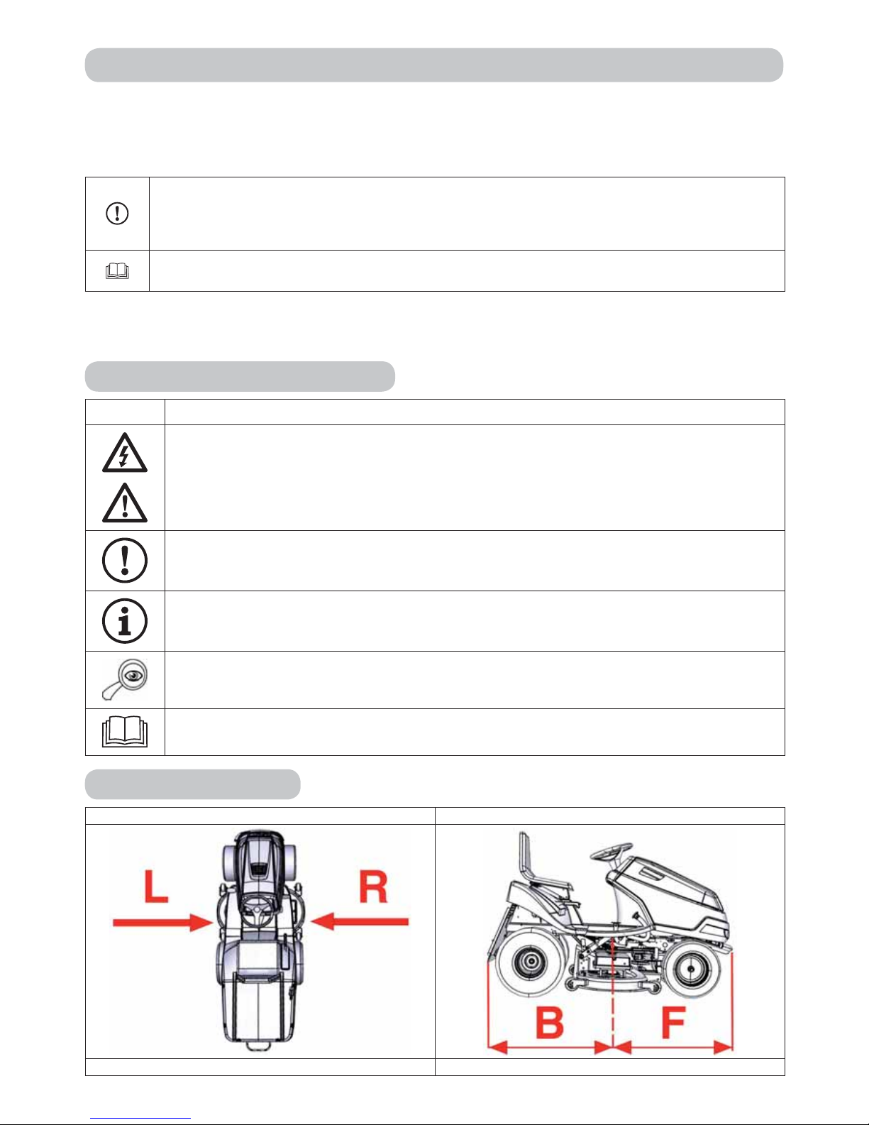
Symbols used in this manual
SYMBOL MEANING
These symbols mean “CAUTION” and “WARNING” and point to factors that could damage
the machine and/or severely injure the user.
This symbol indicates an important instruction, characteristic, practice or issue that must
be followed or kept in mind when setting up, using and maintaining the machine.
This symbol indicates useful information related to the machine or accessories.
This symbol refers to the illustration in the front portion of the manual. It is always
accompanied by the illustration number.
This symbol refers to another chapter of this or another manual. It is usually accompanied
by the number of the chapter to which it refers.
Links to guidelines
Left and right sides Back and front ends
L = left side, R = right side B = back end, F = front end
Page 23

23
1. TECHNICAL INFORMATION
1.1 Use
Model AJ102, AJ102 4X4 or AG122 machines bearing the STARJET brand are double-axled self-
propelled lawn mowers that are intended for cutting flat, maintained lawns with a maximum
growth height of 10 cm, e.g., in parks, gardens and playgrounds, or on gentle slopes that do not
contain foreign objects (fallen branches, stones, solid objects, etc.). The slope must not exceed
10° (17%), when using the 4 x 4 drive, the slope must not exceed 15° (27%).
The machine of type AJ110 is a biaxial, self-propelling mowing machine, destined for mulching of
maintained and non-maintained growths to a height of an approximate minimum of 60 cm
1 x a year, for instance in meadows or parks, possibly on moderate slopes, free from extraneous
objects (fallen branches, stones, solid objects and the like.). The slope must not exceed 10° (17%)
and when using 4 x 4 drive, the slope must not exceed 15° (27%).
Any use of this self-propelled mower that is not mentioned in this manual or that
extends beyond the range of use mentioned is considered use that violates the
purpose. The user bears exclusive responsibility for all such use, and the manufacturer is
not responsible for damages arising therefrom. The user is also responsible for adhering
to the conditions prescribed by the manufacturer for operation, maintenance and repair of
this machine, which must be used, maintained and repaired only by persons who are
familiar with it and who have been instructed in safety.
Only manufacturer-approved accessories can be attached to the machine. Using
non-approved accessories will immediately void the warranty.
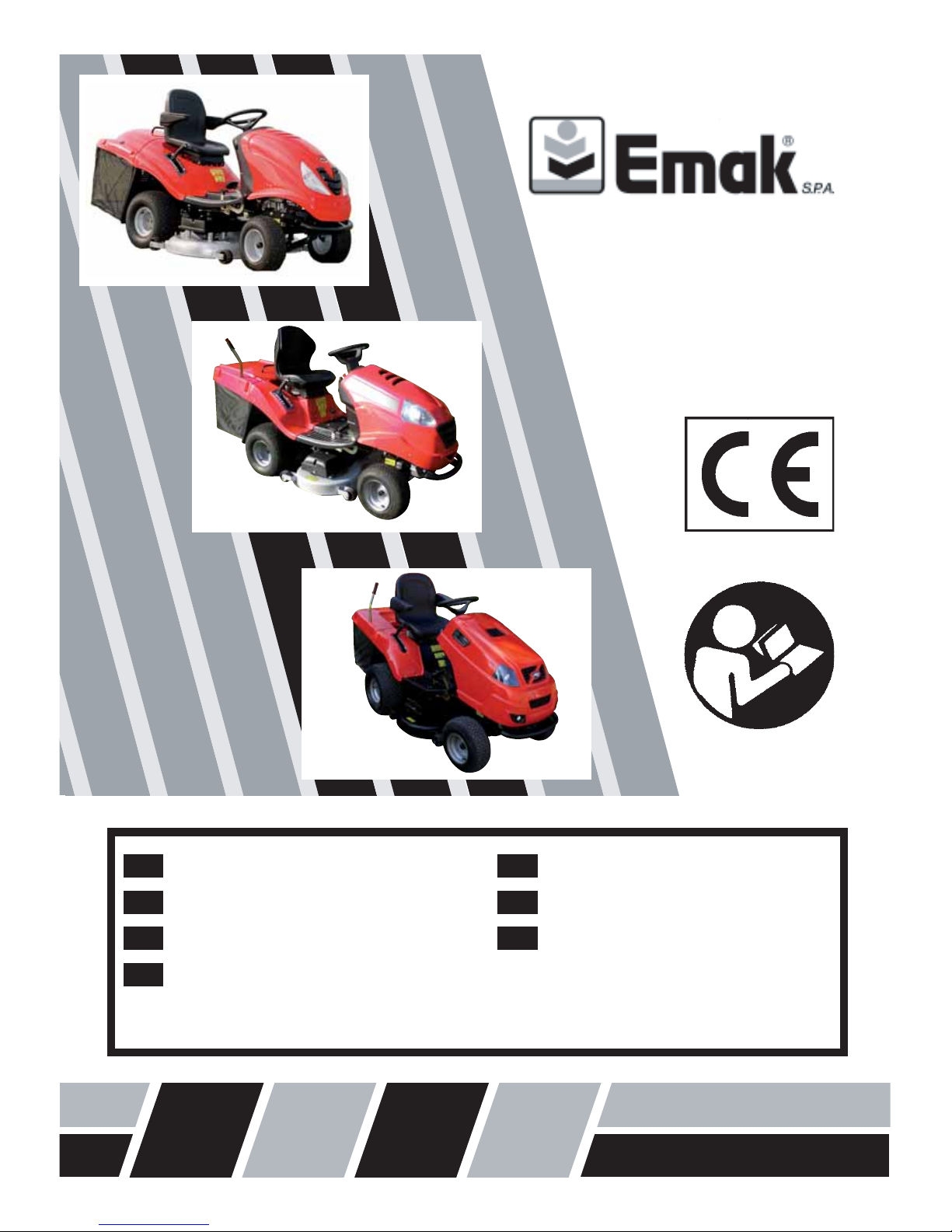
1.2 MAIN PARTS OF THE MOWER
AJ102, AJ202 4X4, AJ110 and AG122 lawn mowers consist of the following basic assemblies:
1.2
(1) Frame and bumper
The frame and bumper support most of the machine’s main parts.
(2) Front axle and wheels, including steering mechanism
The front axle allows the wheels to be steered. Steering is done with a steering wheel.
(3) Mowing mechanism
The mowing mechanism of machines AJ102, AJ102 4x4, AG122 ensures the mowing and
collection of grass. It is located under the machine and consists of a cover, a main plate and
two mowing knives.
The mowing mechanism of machine AJ110 provides the mulching of grass without collection.
It consists of a cover, a belt manifold and six mowing knives arranged in pairs on three
rotating shafts.
(4) Grass removal tube
Connects the mowing mechanism to the grass catcher. Here the mown grass passes into the
the storage container (machine AJ110 is not provided with a tunnel).
(5) Transmission and rear-wheel drive
The transmission box and hydrostatic transmission are for shifting gears when driving.
(6) Bypas s
The bypass lever is for engaging and disengaging power from the transmission to the rear
wheels. It is located near the left rear wheel and, depending on the machine’s design, is
either in front of or behind the wheel.
(7) Grass catcher
The grass catcher, located at the back of the machine, and consists of a steel tube frame, a
fabric bag and a dumping lever.
Page 24
24
1.2
(8) Driver’s area
The comfortable seat allows easy access to all of the machine’s controls.
(9) Bonnet, engine, wiring and battery
The bonnet is a combination of plastic and metal covers that appropriately cover the machine’s
electrical and mechanical parts. Located under the hood is a 4-stroke petrol engine that is
secured to the frame. Depending on the machine’s design, the battery is located either in a
box below the seat or under the front bonnet.
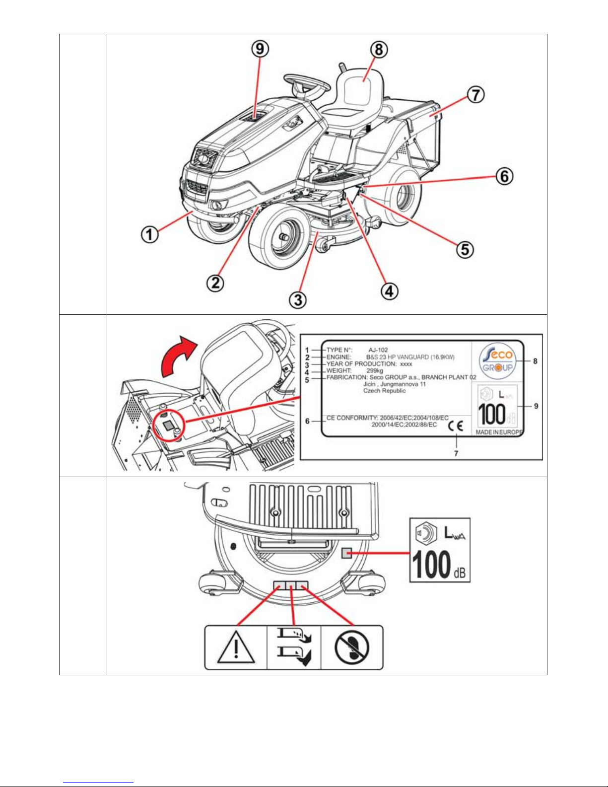
1.3 MANUFACTURING PLATE AND OTHER LABELS USED ON THE MACHINE
1.3.1 MANUFACTURING PLATE
Each self-propelled mower is marked with the manufacturer’s label, located below the seat. You can
access it by lifting the seat.
1.3.1
1. Mower model
2. Engine model
3. Model year
4. Weight
5. Name and address of manufacturer
6. EC product conformity regulations
7. Product conformity symbol
8. Manufacturer’s logo
9. Guaranteed noise level according to regulation 2000/14/EC
The vendor will write the serial number of your machine on the back cover of this manual.
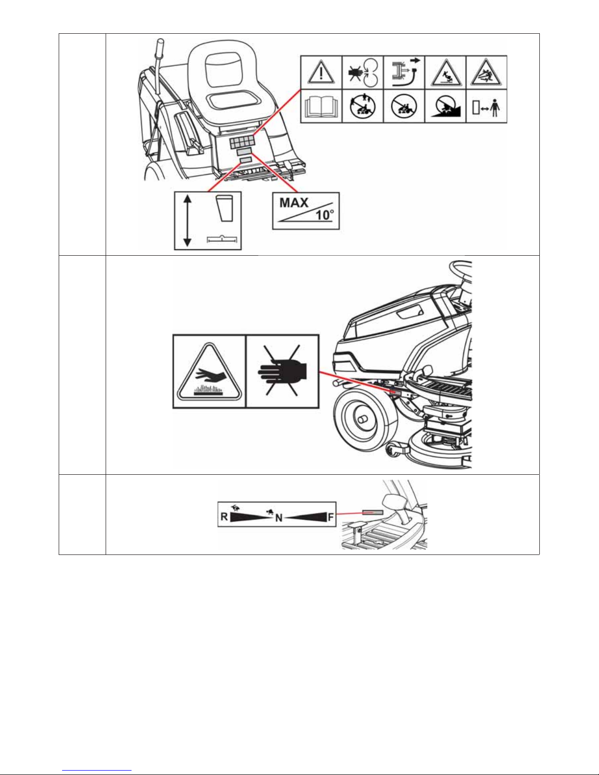
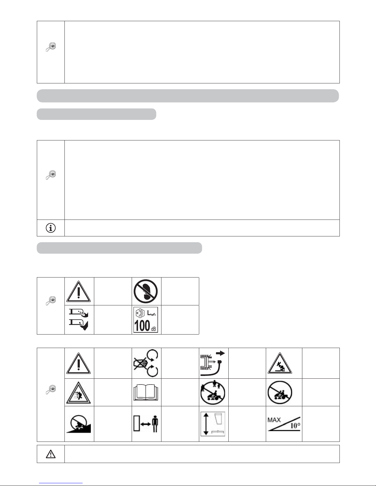
1.3.2 OTHER LABELS AND THEIR MEANING
The following labels and stickers are fastened to your machine:
Labels on the left side of the mower:
1.3.2a
Danger
Keep feet
clear
Rotating
tools
Guaranteed
noise level
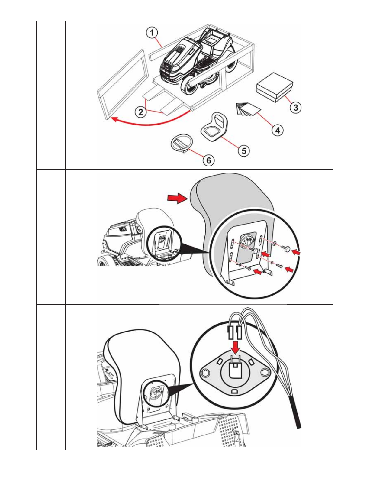
Labels on the canopy below the seat:
1.3.2b
Danger
Do not
touch during
operation.
Repair
according to
manual.
Do not
let the
machine run
unattended.
Beware
of flying
objects!
Read the
manual
Do not mow
near other
people.
No riders
Do not drive
across a
slope.
Keep
unauthorized
persons at a
safe distance.
Switching
the mulching
flap
Maximum
working
slope
It is strictly prohibited to remove or damage labels or symbols attached to the mower.
If a label is damaged or illegible, contact your dealer or the manufacturer for a replacement.
Page 25
25
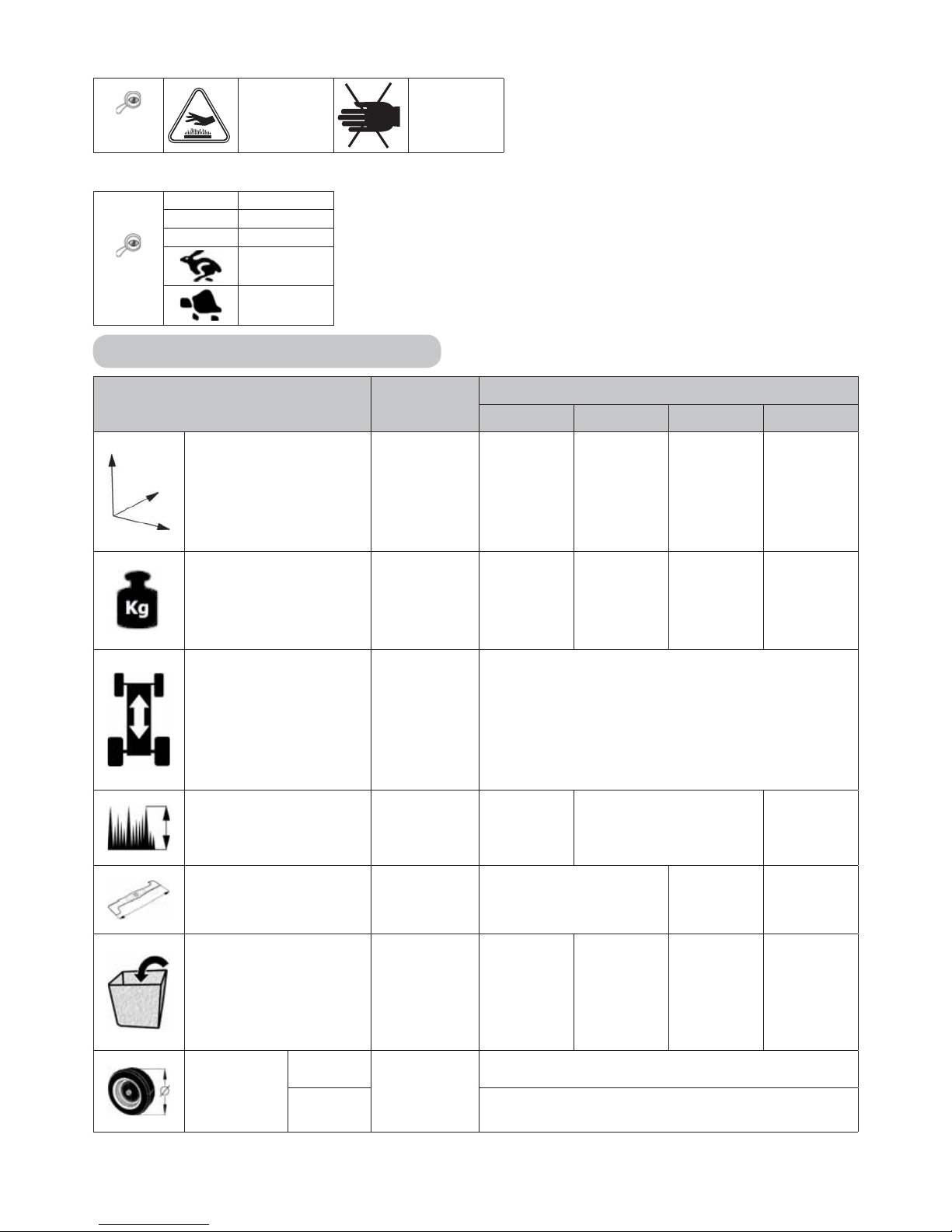
Labels on the left and right side of the machine:
1.3.2c
Careful
Hot surface!
Danger of
burns
Labels near the undercarriage pedal:
1.3.2d
R Reverse
N Neutral
F Forward
Fast
Slow
1.4 TECHNICAL PARAMETERS
BASIC SPECIFICATIONS UNIT
MOWER MODEL
AJ102 A102 4x4 AG122 AJ 110
Dimensions
(length x width x
height)
[mm]
2400 x
1060 x
1100
2480 x
1060 x
1305
2450 x
1270 x
1200
2450 x
1140 x
1200
Weight [kg]
255– 320
according
to the
type of
machine
319 290
302 – 332
according
to the
type of
machine
Speed forward /
reverse
[km/h] 8 / 4
Cutting height [mm] 30 - 90 30 - 80 40 - 100
Cutting stroke [mm] 102 122 110
Grass catcher volume [l]
300, 360
according
to the
type of
machine
360
300, 360
according
to the
type of
machine
Without
storage
container
Wheel
dimensions
Front
["]
16 x 6.50-8
Rear 20 x 10-8
Page 26

26
BASIC SPECIFICATIONS UNIT
MOWER MODEL
AJ102 A102 4x4 AG122 AJ 110
Fuel tank capacity [l]
7,5
(13; 15)
according
to the
type of
machine
13 (15)
based on
type
13 (15)
according
to the
type of
machine
7,5
(13; 15)
according
to the
type of
machine
Guaranteed acoustic
output level L
WA
[dB] < 100* < 105* < 100*
Declared noise
emission level at the
operator L
pAd
per EN
ISO 11201
[dB] < 90* < 90* < 90*
Battery type ---
12V 32 Ah (BS Vanguard 23HP motors)
12V 24 Ah (other engines)
* - For exact values, see the charts on the next page.
AJ102 Mower
Engine
RPM ± 100
(min-1)
Declared noise
emission level at the
operator L
pAd
(dB)
per EN ISO 11201
Guaranteed
acoustic
output level
LWA (dB)
Weighted RMS acceleration (min.s-2)
Seat
Steering
wheel
Floor
BS15 2700 85.0 100 0.16 2.48 1.72
BS16 2800 83.1 100 0.30 1.52 0.73
BS17I 2700 86.0 100 0.94* 3.34**
BS18 2800 83.3 100 0.50 1.38 1.20
BS18I 2800 83.1 100 0.41 1.75 1.19
BS19I 2700 86.0 100 1.3+0.5* 3.7+1.9**
BS20I 2800 84.5 100 0.17 2.07 1.59
BS22I 2800 84.0 100 0.9+0.4* 6.0+2.4*
BS20 2800 86.0 100 0.19 2.75 1.34
BS23 2800 84.0 100 1.6+0.6* <2.5**
HO16 2800 85.0 100 0.93* <2.5**
* Aggregate value of acceleration (m.s
-2
) per EN 836+A1/A2, appendix G
- * of total a
vd
vibration per EN 1032+A1
- ** vibration transferred to arm a
hvd
per EN 1033+A1
AJ102 4x4 Mower
Engine
RPM ± 100
(min-1)
Declared noise
emission level at the
operator L
pAd
(dB)
per EN ISO 11201
Guaranteed
acoustic
output level
LWA (dB)
Vibration acceleration aggregate value
(m.s-2)
total vibrations, a
vd
transferred to arm,
a
hvd
BS23 2800 86 + 4 100 0.9 + 0.5 < 2.5
BS24I 2800 84 + 1.8 100 1.0 + 0.4 2.7 + 1.4
Page 27

27
AJ122 Mower
Engine
RPM ± 100
(min-1)
Declared noise
emission level at the
operator L
pAd
(dB)
per EN ISO 11201
Guaranteed
acoustic
output level
LWA (dB)
Weighted RMS acceleration (min.s
-2
)
Seat
Steering
wheel
Floor
BS18 3000 84.6 105 0.14 2.16 1.35
BS20I 3000 89.8 105 0.31 2.53 1.67
BS20 3000 86.6 105 0.19 2.75 1.34
BS22I 3000 87 105 0.9* 2.66**
Specific data on your mower can be found in the following charts according to the model number shown
on the inside cover of this publication.
AJ110 Mower
Motor
RPM±100
(min-1)
Declared noise
emission level at the
operator L
pAd
(dB)
per EN ISO 11201
Guaranteed
acoustic
output level
LWA (dB)
Vibration acceleration aggregate value
(m.s
-2
)
of total vibrations
a
vd
transferred to arm
a
hvd
BS22I 2900 100
BS24I 2900 100
BS23 2900 84 + 4 100 1.1 + 0.4 <2.5
Explanatory notes:
Engines: Transmissions:
BS15 Briggs & Stratton 15.5-hp I/C AVS
BS16 Briggs & Stratton 16-hp VANGUARD V-TWIN
BS17I Briggs & Stratton 17.5-hp INTEK
BS18 Briggs & Stratton 18-hp VANGUARD V-TWIN
BS20 Briggs & Stratton 20-hp VANGUARD V-TWIN
BS23 Briggs & Stratton 23-hp VANGUARD V-TWIN
BS18I Briggs & Stratton 18-hp INTEK
BS19I Briggs & Stratton 19.5-hp INTEK
BS20I Briggs & Stratton 20(21)-hp INTEK
BS22I Briggs & Stratton 22-hp INTEK
BS24I Briggs&Stratton 24HP INTEK
HO16 Honda 16-hp GCV530
TT46 TUFF-TORQ K46
TT62 TUFF-TORQ K62
TT664 TUFF-TORQ K664 + KXH 10
2. OCCUPATIONAL SAFETY
STARJET brand AJ102, AJ102 4x4, AJ110 and AG122 self-propelled mowers are manufactured
according to applicable European safety norms. The manufacturer confirms this in the Declaration of
Compliance included at the end of this manual ( 10).
If this machine is used properly and according to the manual, it is very safe.
If the user does not adhere to work safety and does not heed the warnings in this
manual, this self-propelled lawn mower can sever a hand or a foot, or even hurl
objects, leading to serious personal injury or death, damage or destruction of the
machine, or of some of its parts or accessories.
Page 28

28
2.1 SAFETY INSTRUCTIONS
The user bears primary responsibility for his or her own safety and that of other people during operation
of the mower. The machine’s manufacturer bears no responsibility for personal injury, damage to the
machine or ecological damage caused by use and operation not in keeping with all safety instructions
given in this manual.
2.1.1 General safety instructions
! This machine may be operated only by persons 18 years or older who are familiar with this user
manual.
! The user of the machine is responsible for the safety of persons present in the machine’s operating
area.
! It is prohibited to perform any technical modifications without prior written consent of the manufacturer.
Unauthorized modifications may lead to hazardous working conditions and void the warranty.
! Adhere to all fire safety regulations ( 2.4).
! Do not remove the safety stickers and labels from the machine.
! Do not go near or underneath the machine if it has been raised and is not sufficiently secured against
falling or overturning.
! Subjecting components of the grass catcher to stress can damage them, reduce their function or cause
objects to fall out of the catcher. Therefore, check them regularly according to the recommendations
in this manual.
! Always switch off the mowing mechanism and the engine and remove the key from the ignition when:
cleaning the machine
unclogging the mowing mechanism
checking the machine for damage or repairing it after driving over a foreign object
checking for the cause of excessive vibration
repairing the engine or other movable parts (also disconnect the ignition cable)
2.1.2 Before using the machine
! Do not use the machine if it is damaged or missing safety equipment. All protective covers and safety
elements must be in place at all times. Do not remove or disable any safety devices. Regularly inspect
those devices for correct operation.
! Do not use the machine when under the influence of alcohol, medication or narcotics.
! Do not work with the machine if you suffer dizziness or fainting, or if you are otherwise weakened or
unable to concentrate.
! Before operating the machine, thoroughly familiarize yourself with all the controls and master their
operation so that, if necessary, you can immediately stop the machine or shut off its engine.
! Do not change the settings of the engine regulator or engine speed limiter.
! Before working with the machine, clear the mowing surface of all stones, wood, wires, bones, fallen
branches and other foreign objects that the machine may throw during operation.
! Repair all defects before further use. Before starting work, thoroughly inspect the V-belt tension, the
sharpness of the mowing blades and the cleanliness of the mowing mechanism cover.
2.1.3 While using the machine
! The machine must not be used on slopes of more than 10° (17%), when using drive 4x4 on a slope
exceeding 15°(27%).
! Transporting other people, animals or objects on the machine is prohibited. Objects may be transported
only on a trailer approved by the machine’s manufacturer.
! Even when leaving the machine for a short time, always remove the ignition key.
! If you are driving the machine outside the mowing area, always shut off the mowing mechanism and
raise it to transport position.
Page 29

29
! Never mow near dumps, holes or river banks. If a wheel gets too close to the edge of a hole or ditch,
the mower may suddenly overturn.
! While working, keep clear of molehills, concrete supports, tree stumps and the curb stones of gardens
and streets. These may come into contact with the blades and damage the mowing mechanism and
the machine itself.
! If you run into a solid object, stop the machine, shut off the mowing mechanism and the engine, and
check the whole machine, especially the steering mechanism. If necessary, repair any damage before
restarting the machine.
! Where possible, avoid working with the machine on wet grass. Reduced traction may cause skidding.
! Avoid obstacles (e.g., sudden changes in slope, ditches, etc.) that could overturn the machine.
! Do not try to maintain the machine’s stability by stepping on the ground.
! Use the machine only in daylight or under sufficient artificial light.
! Do not drive the machine on public thoroughfares.
! When operating the machine, do not wear loose clothing or short trousers; wear strong, closed work
shoes. Never operate the machine barefoot or in sandals.
! Do not leave the engine running in enclosed spaces. Exhaust gases contain poisonous substances that
have no odour but are nonetheless fatal.
! Do not place your hands or feet under the mowing mechanism cover. Never bring any part of your body
near the machine’s rotating or moving parts.
! Do not start the engine without the exhaust pipe.
! The noise that occurs during mowing does not ordinarily exceed the highest acoustic pressure
and volume values shown in this manual (
1.4). However, under some conditions, due to terrain
characteristics, the noise level may briefly exceed specified levels.
! The manufacturer recommends wearing ear protectors while operating the machine. Stress placed on
the auditory organs by high volume levels or the long-term effects of noise can permanently damage
hearing.
! Always give your full attention to driving and the other activities involved in using the machine. The
most common ways to lose control over the machine are:
Loss of traction.
Driving too fast; not adapting speed to the surface conditions and characteristics.
Abrupt braking that can lock the wheels.
Using the mower for purposes other than those intended.
2.1.4 After working with the machine
! Always keep the machine and its accessories clean and in good working order.
! The rotating blades are sharp and may cause injury. When handling the blades, wrap them or wear
protective gloves.
! Regularly check the nuts and bolts that hold the blades, and make sure they are tightened to the right
level of torque ( 6.3.6).
! Pay special attention to the self-locking nuts. After a nut has been removed twice, its self-locking
ability is reduced, and it must be replaced with a new one.
! Regularly check the components and, when necessary, replace them according to the manufacturer’s
recommendation.
2.2 SAFETY INSTRUCTIONS FOR WORKING ON SLOPES
Slopes are a main cause of accidents, loss of control and overturning. These can lead to severe injury or
death. Always use extra caution when mowing on slopes. If you are not sure or are unable to mow on a
slope, don’t do it.
! The self-propelled mower can be used on slopes of no more than 10° (17%), when using the 4x4 drive
at a maximum slope of 15° (27%) and only vertically, i.e., upward or downward. More information
5.5.4.
! Extra caution is necessary when turning. Do not turn around on a slope unless absolutely necessary.
Page 30

30
! Beware of holes, roots or uneven terrain. Uneven terrain may cause your machine to overturn. Tall
grass may conceal dangerous obstacles. Therefore, remove all obstacles from the mowing surface
ahead of time.
! Select a speed that will not require you to stop on a slope.
! Be very careful when attaching the grass catcher or other attachments. They may reduce the machine’s
stability.
! Always move slowly and smoothly on a slope. Do not change speed or direction suddenly.
! Avoid starting or stopping on a slope. If the wheels lose traction, turn off power to the blades and
slowly drive down the slope.
! Accelerate very slowly and carefully on slopes, to prevent the machine from lurching. Before a slope,
always reduce the engine speed. Especially when driving downward, reduce the speed to the minimum
for using the transmission’s braking effect.
2.3 CHILD SAFETY
If the operator is not alert to the presence of children, a tragic accident may occur. The mower’s
movement attracts their attention. Never assume that children will stay where you saw them last.
! Never leave children unsupervised in mowing areas.
! Be alert and ready to stop your machine in case of an emergency.
! Before and and while backing up, look to the rear and at the ground.
! Never transport children on the mower. They can fall and be severely injured or dangerously interfere
with your operation of the mower. Never allow children to operate the machine.
! Take extra care in areas of limited visibility (near trees, bushes, walls, etc.).
2.4 FIRE SAFETY
While using the mower, you must observe all work and fire safety rules relevant to this type of machine.
! Regularly remove flammable materials (dry grass, leaves, etc.) from the area of the engine exhaust,
battery and anywhere where they might come into contact with petrol or oil, ignite and set the machine
on fire.
! Allow the mower’s engine to cool before storing it in an enclosed space.
! Use extra caution when working with petrol, oil and other flammable substances. These are highly
flammable substances, and their fumes are explosive. Do not smoke while working. Never unscrew the
fuel cap, and never add fuel when the engine is running or is warm, or if the machine is in an enclosed
space.
! Check the fuel flow before use; do not fill the tank up to the neck. Engine heat, sun and the expandability
of fuel may lead to overflow and result in fire. Use only approved containers for storing flammable
substances. Never store the machine or fuel container near any heat source. Use extra caution when
handling the battery. Battery gases are highly explosive. Do not smoke or use an open flame when
handling the battery, as this may cause serious injury.
3. PREPARING FOR OPERATION
3.1 UNPACKING AND CONTENT INSPECTION
The self-propelled mower is delivered in a fabric cover (1). Some parts of the machine have been
dismantled for transport at the factory, and they must be installed before operation. The machine is
unpacked and prepared for operation by the dealer as part of pre-sale service.
- After delivery, immediately check to see if the packaged machine is damaged. If there is
damage, notify the carrier. If a claim is not made on time, it cannot be honoured.
- Check to see that the machine is the model you ordered. If it is the wrong model machine,
do not unpack it, and immediately alert the supplier.
Page 31

31
After removing the cover, carefully remove the machine from the pallet. This requires preparation of
ramps (2) to avoid damage to parts of the machine. Make sure that there is no shipping damage. Also
unpack all dismantled parts and inspect them.
3.1
1. Fabric cover
2. Ramps
3. Grass catcher
4. Documentation
5. Seat
6. Steering wheel
The basic package includes:
Mower
Steering wheel (6)
Seat (5)
Grass catcher (3) (comes partially disassembled in a cardboard box, with a hanger, connectors and two
triangular yellow stickers) ( 3.3.2) – absent in the case of machine AJ110!
Documentation (4) (packing list, user manual for mower, engine manual, battery manual and service
book)
3.2 DISPOSAL OF PACKAGING
After unpacking the accessories, make sure you properly dispose of and recycle
the packaging material.Comply with applicable waste disposal laws in the user’s
country.
Disposal can be entrusted to a specialized company.
3.3 ASSEMBLING PACKED UNITS
Because it is technical work, your dealer will prepare the mower for operation (according to
the following instructions).
Before starting installation, remove all protective materials, place the mower on a flat surface,
and align the front wheels in forward position.
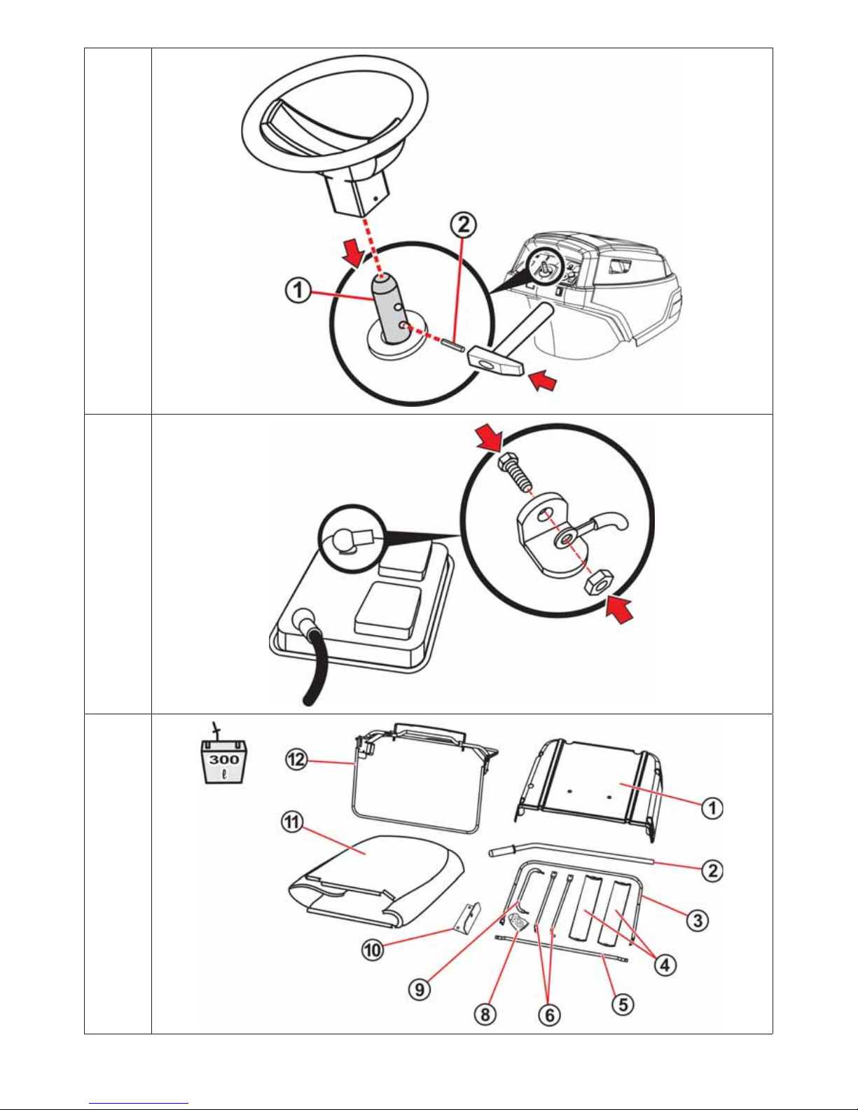
3.3.1 STEERING WHEEL, SEAT AND BATTERY
a) Fasten the seat:
Place the seat in its place on the machine and secure it using four bolts, pre-mounted
in the seat. Before tightening the bolts, set the desired position of the seat to match
your body size.
3.3.1a
b) Connect the cable to the safety switch:
Connect the electrical cable to the switch connector at the bottom of the seat.
3.3.1b
c) Install the steering wheel:
Place the wheel on the column (1) and turn it so that the holes in the steering wheel
and column meet.
Insert the included peg into the hole (2) and pound it with a hammer.
3.3.1c
Page 32

32
d) Connect the battery:
3.3.1d
Depending on the machine’s design, the battery is located either in a box below
the seat or under the front bonnet.
Loosen the bolts on the battery’s pole terminals.
Attach the red cable to the battery’s positive (+) pole and secure it with the bolt.
Attach the brown cable to the battery’s negative (–) pole and secure it with the bolt.
- Connecting the cables backwards can damage the machine.
- When disconnecting the battery, always disconnect the negative (–) terminal first.
- When installing, using and maintaining the battery, follow the instructions described in the
battery manual. At the same time, observe all of the manual’s safety instructions.
3.3.2 GRASS CATCHER (only present in types AJ102, AJ102 4x4 and AG 122)
The grass catcher is delivered in a separate box. Some of its parts have been dismantled for transport
and must be assembled first. Later chapters give a rough outline on assembling it. The complete process
is shown on the DVD that is included or can be sent upon request.
TOOLS NEEDED
Prepare the following tools for assembling the catcher:
A knife for removing packing
material
A set of hexagonal socket
wrenches and hex wrenches
Phillips screwdrivers or an
electrical hand screwdriver
UNPACKING
Remove the packing material. First take out the lid, frame and sack and then the wrapped individual
parts. Unpack these parts and clearly organize them in an appropriate place.
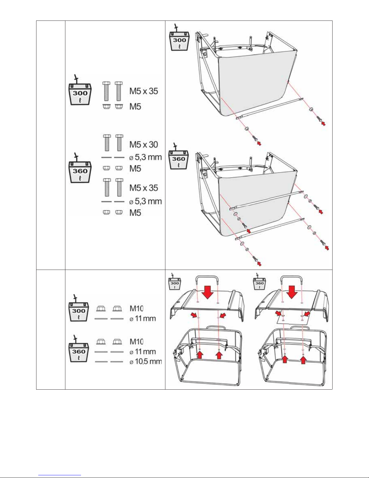
PACKAGE CONTENTS
300-litre grass catcher
3.3.2a
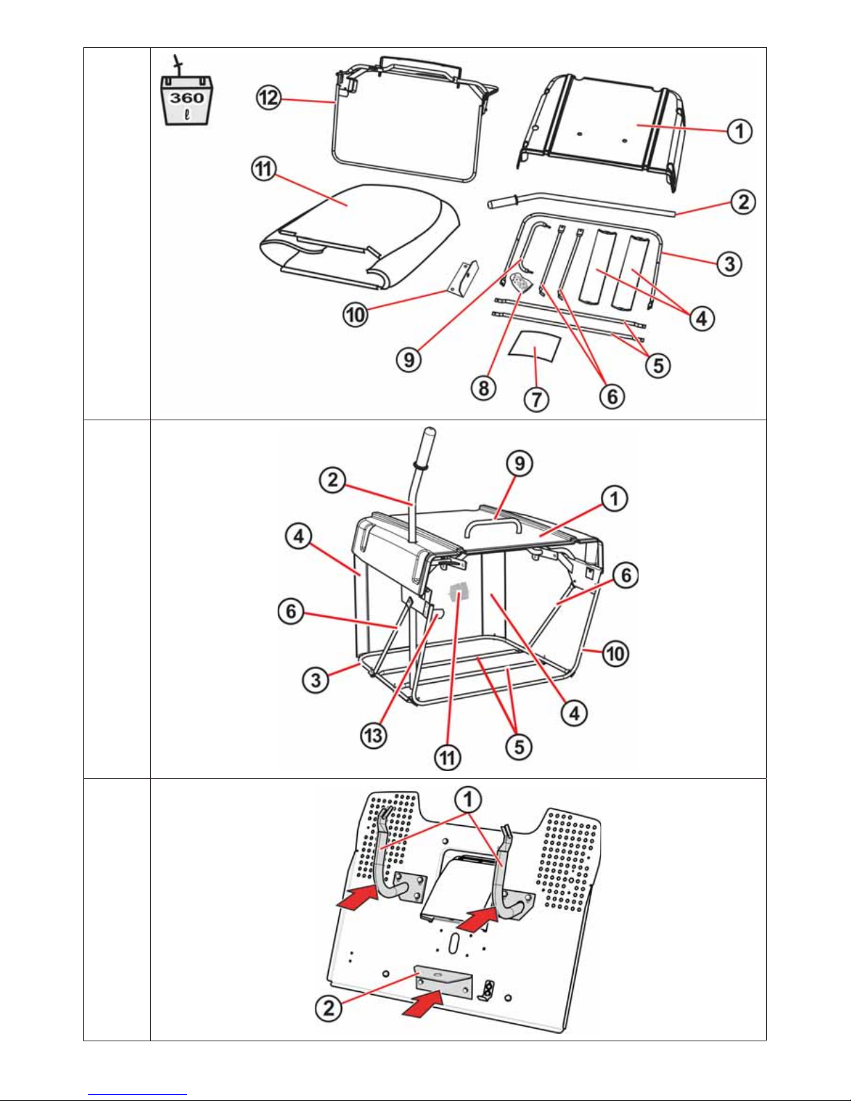
360-litre grass catcher
3.3.2b
(1) - Lid
(2) - Lifting lever
(3) - Lower tube
(4) - Corner braces (left and right)
(5) - Lower brace
(6) - Side struts
(8) - Fastening bolts, nuts and washers
(9) - Handle
(10) - Lower bracket
(11) - Sack
(12) - Frame
(1) - Lid
(2) - Lifting lever
(3) - Lower tube
(4) - Corner braces (left and right)
(5) - Lower brace
(6) - Side struts
(7) - Metal sheet
(8) - Fastening bolts, nuts and washers
(9) - Handle
(10) - Lower bracket
(11) - Sack
(12) - Frame
Page 33

33
Four replacement shear pins for the cutting blades are packaged with the grass
catcher.
Store these pins for later use.
GRASS CATCHER - MAIN PARTS (TERMINOLOGY)
(1) - Lid
(2) - Lifting lever
(3) - Lower tube
(4) - Left and right corner brace
(5) - Lower brace (in the 300l version only 1x)
(6) - Side struts
(9) - Handle
(10) - Front tube
(11) - Sack (mesh)
(13) - Control grass tipping bracket
3.3.2c
INSTALLING THE GRASS CATCHER
Screw the grass catcher hinges (1) and hinges (2) on to the rear plate.
3.3.2d
- On some machines, the hinges (1) are already pre-mounted on the rear plate.
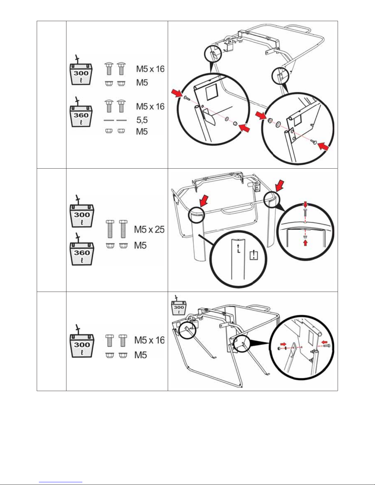
- Hinge (2) is attached only if a trailer is used.
Into the upper holes in the brace that fastens the front tube above, insert M5x16 bolts,
secure them with washers and nuts, and lightly tighten them. Also tighten the lower,
pre-inserted bolts.
3.3.2e
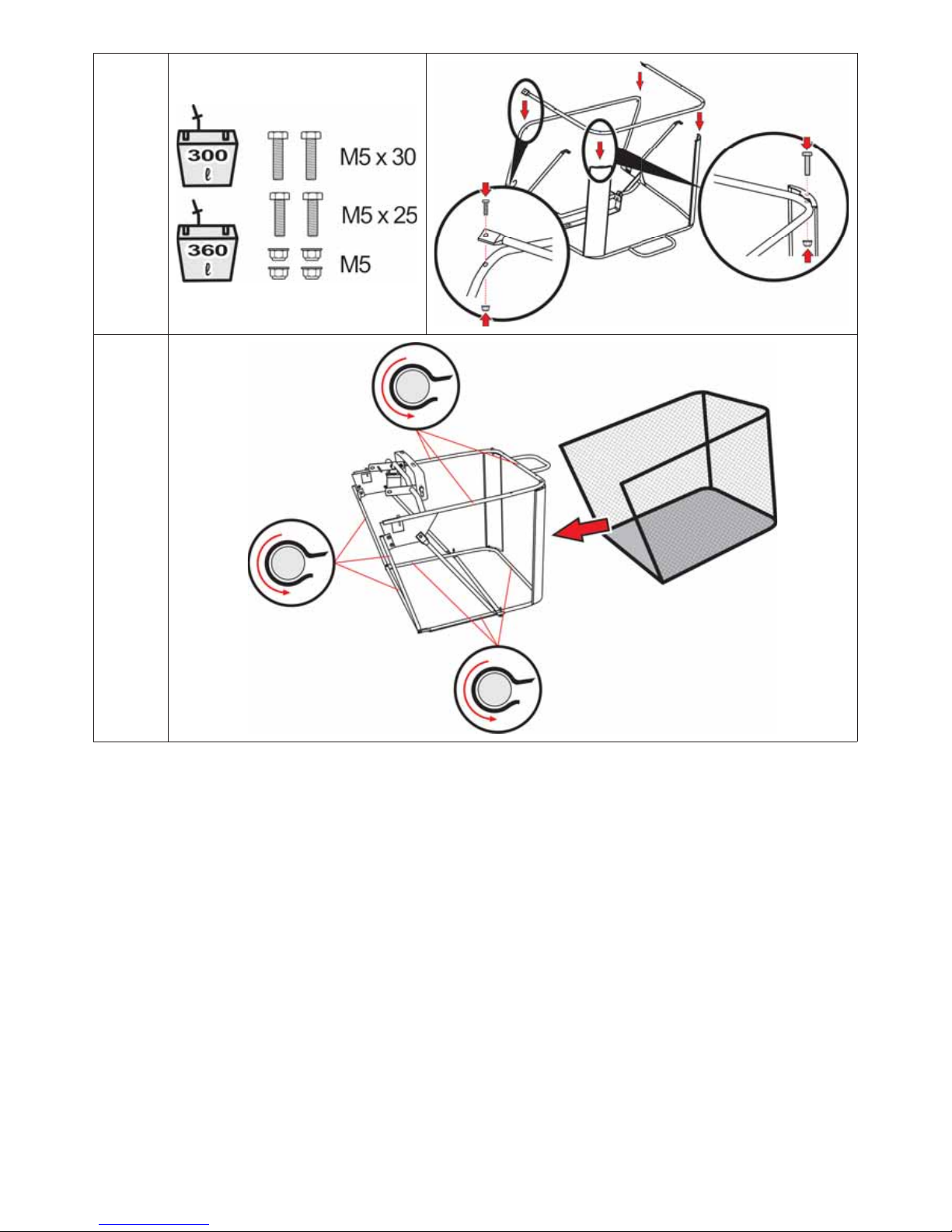
Attach two corner braces to the frame using M5x25 bolts and nuts. Make sure not to get
the left brace and right brace switched. The left brace is clearly marked “L”.
3.3.2f
Screw on the side struts of the grass catcher. The struts are attached to the inner side of
the grass catcher using M5x16 bolts and nuts.
3.3.2g
For the catcher on the 360-litre model, ignore this point — the side braces are premounted.
Screw the bottom tube to the frame. For easier assembly, we recommend that the grass
catcher is turned upside down. From the underside attach the bottom tube to the corner
braces using M5x25 bolts and to the front frame using M5x30 bolts. After attaching turn
the grass catcher back over.
3.3.2h
Slide the grass catcher sack on to the frame. Pull the rubber sides of the sack over the
tubes.
3.3.2i
From the underside of the grass catcher bolt in the lower braces ( 3.3.2c, note. 5).
Attach them using M5x30 and M5x35 bolts to the lower tube and to the side braces.
3.3.2j
For 300 l grass catchers only a single lower brace is attached. It is screwed to the side
braces using M5x35 bolts.
Page 34

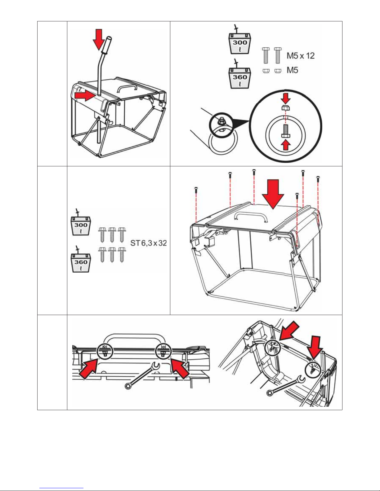
34
300 l grass catchers: Into the openings in the lid insert the handle and slide washers on
to its threaded ends. Insert the piece assembled in this way through the openings in the
top bracket on the frame and secure the handle using nuts. Do not tighten them yet!
360 l grass catchers: Into the openings in the lid insert the handle and slide washers
(black) on to its threaded ends. Also slide the metal sheet and also one more set of washers
on to them. Insert the piece assembled in this way through the openings in the top bracket
on the frame, slide more washers on to the threaded ends and secure everything using
nuts. Do not tighten them yet!
3.3.2k
Bolt the lid to the frame and tighten the bolts.
3.3.2l
Insert the emptying lever into the holes in the brace inside the catcher.
Into the lower end of the lever inside, insert a bolt and push its threaded portion through
the hole. Secure it from above with a nut and tighten it.
3.3.2m
Firmly tighten the nuts securing the handle and tighten the nuts securing the top bracket
of the frame. This completes the installation of the grass catcher.
3.3.2n
BALANCING AFTER INSTALLATION
Take hold of the grass catcher and hang it on the hangers on the rear plate of the machine.
Check its fit to the fenders. Correct any imbalance by loosening the bolts in the front tube and/or the
bolts in the side braces, evening it up and retightening the bolts.
On a properly adjusted grass catcher the space between the rear plate of the machine and
the front tube (3) (
3.3.2c) is no greater than 5 mm.
If the catcher cannot be fit in the manner explained above, balance it by shifting its hangers on the
rear plate.
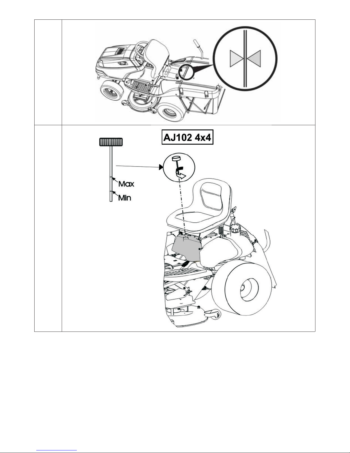
After balancing the catcher, adhere the triangular sticker (included) on its lid. Place it
across from the sticker that is already adhered to the machine’s cover. The tips of the
triangles must be in opposing positions.
3.3.2o
3.4 INSPECTING BEFORE STARTUP
3.4.1 CHECKING THE ENGINE OIL
Before checking the oil, the tractor must be in a horizontal position. The oil cap can be accessed by lifting
the seat. Unscrew the dipstick, wipe it clean, reinsert it and screw it back in. Then unscrew it again and
read the oil level.
Oil level on dipstick:
(1) - (ADD) oil is low
(2) - (FULL) oil is full
The oil level must be between the two marks on the dipstick. If it is not, add motor oil until it reaches
the “FULL” mark. The oil type is designated in a separate manual from the engine manufacturer.
The oil must be checked before every ride.
3.4.2 BATTERY INSPECTION
Check the battery according to the manual provided by its manufacturer.
Page 35

35
3.4.3 FILLING THE FUEL TANK
For safety reasons, the mower is transported without fuel, and it is necessary to fill the tank before
starting up for the first time. Depending on the machine’s design, the fuel tank is located either under
the front bonnet or inside the left fender, and holds 7,5 l (types with container under the hood) or
13 (15) l (types with contanier in the mudguard) of fuel.
- Use only fuel of the octane rating designated in the engine manual. Defects caused by
improper fuel are not covered by the warranty!
- Fill the tank only when the engine is switched off and is cool. Fill the tank in a well-ventilated
area.
- When handling fuel, do not eat, smoke or use an open flame.
- For filling the tank, use a funnel intended for use with fuel.
- Make sure not to spill any fuel when filling the tank. Spilled fuel is highly flammable. If any
fuel spills, wipe it up until dry.
- Store fuel out of the reach of children.
Filling process:
Remove the fuel tank cap. Open it slowly, because the tank may contain
pressurized petrol fumes.
Insert the funnel into the filling port and pour in fuel from a canister.
After filling the tank, always wipe dry the cap and the area around it. It is
appropriate to check the fuel level through the lines.
We also recommend cleaning the tank itself regularly, because any
contaminants in the fuel can cause engine breakdown.
3.4.4 CHECKING TYRE PRESSURE
Before using the machine, check the air pressure in the tyres.
The air pressure in the front and rear tyres must be within the range
of 80 -140 kPa. The difference between the individual tyres can be
± 10 KPa.
Do not exceed the maximum pressure marked on the tyres that are being used.
3.4.5 CHECKING THE OIL IN THE HYDRAULIC CIRCUIT (only on the AJ102 4x4
machine)
Your machine is delivered with fully operational and fully deaerated hydraulic system and with an
equalising container filled with the correct amount of oil. The oil level may drop down during transport.
On the AJ102 4x4 machine the expansion tank is located under the seat
3.4.5). On other machines
the expansion tank is located in the area of the transmission ( 6.3.16).
Check to see that the oil level is between the two measurement marks on the dipstick of the closing
stopper. If necessary, add the required amount of the specified oil.
When you finish, clean the lid and the intake surrounding with a cloth. Clean the entire tank as well,
because dirt in the oil shortens the oil filter life and may cause breakdowns.
3.4.6 DEAERATING THE HYDRAULIC CIRCUIT (only on the AJ102 4x4x machine)
Complete deaeration of the hydraulic circuit is achieved during the first hours the machine is running.
We recommend breaking the machine in gently for 1 – 2 hours. If during the initial break-in phase the
Page 36

36
hydraulic drive‘s sound changes, the front axle may be aerated. Deaerate by loosening the caps on the
left and right sides of the axle (
3.4.6). When the oil starts to flow out smoothly, tighten the caps
again.
3.4.7 CHECKING THE TIGHTNESS OF THE HYDRAULIC CIRCUIT
Visually inspect the hydraulic system for leakage. Pay special attention to locations where pipes and
armatures are connected. If you discover leakage contact the service centre.
4. CONTROLLNG THE MACHINE
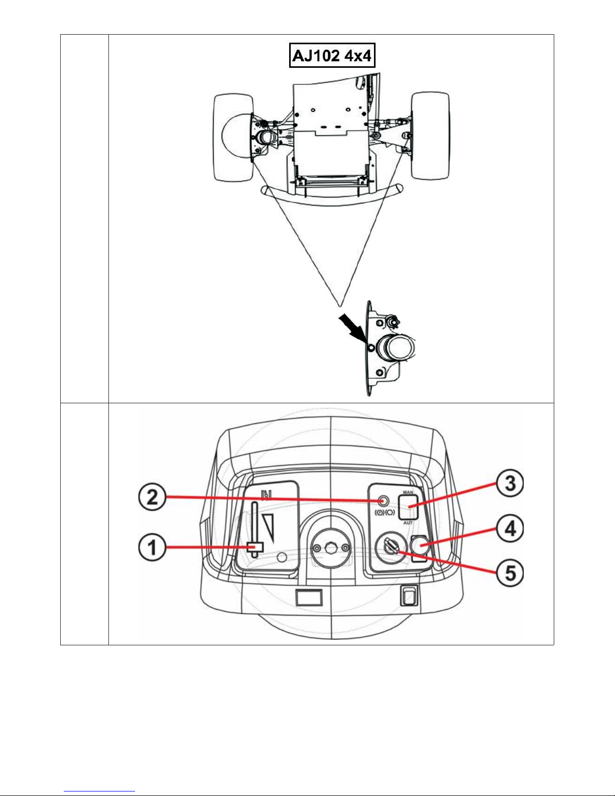
4.1 CONTROL LAYOUT
4.1a
(1) Accelerator lever
(2) Indicator for the brake pedal and parking brake
(3) Mowing function control switch when grass catcher is full
(4) Switch for mowing mechanism
(5) Main switch
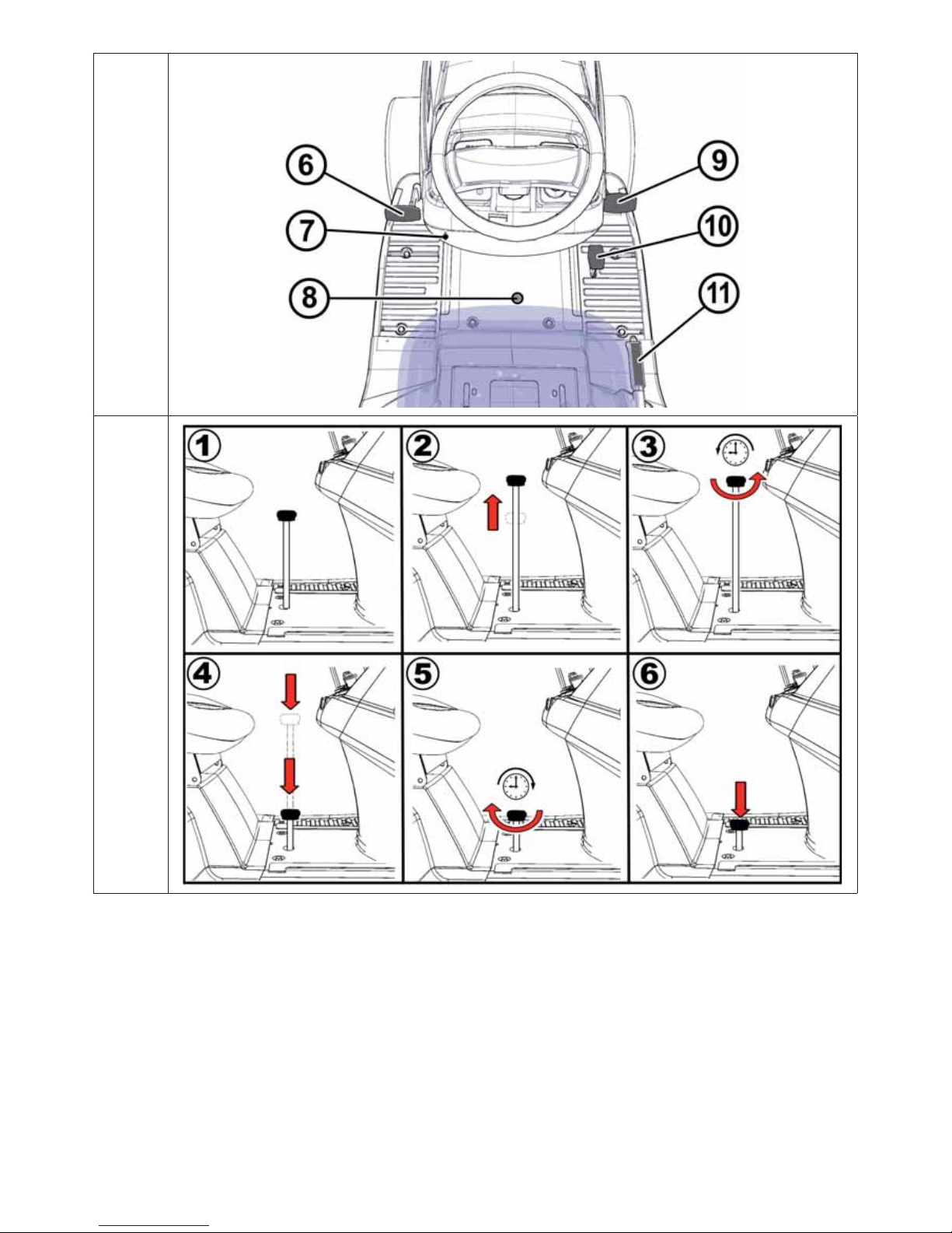
4.1b
(6) Brake pedal
(7) Parking brake control
(8) Mulching lid lever
(9) Forward drive pedal
(10) B ackup pedal
(11) Mowing mechanism height adjustment lever
4.2 DESCRIPTION AND FUNCTION OF CONTROLS
4.2.1 STANDARD CONTROLS
(1) ACCELERATOR LEVER
Regulates engine RPM. Has the following three positions:
STARTER* To cold start the engine
MAX Maximum RPM
MIN Minimum RPM (idle)
* Only on machines with engines BS15, BS17, KO15, TE17 and HO16
Page 37

37
(2) INDICATOR FOR THE BRAKE PEDAL AND PARKING BRAKE
This indicator signals that the brake pedal has been pressed or the parking brake engaged.
Parking brake engagement signal
Brake pedal indicator
(3) Mowing function control switch when grass catcher is full (optional equipm ent)
The AUT/MAN switch turns the mowing function (of the mowing mechanism) on and off when the grass
catcher is full.
In the MAN position, mowing is on all the time, and if the grass catcher is full, the removal tube can fill
with clippings. For this reason this position is intended only for short term use to complete the mowing
of very small remaining areas.
If the machine is equipped with an acoustic indicator (buzzer), then it is automatically
activated when the basket is full.
In the AUT position, mowing is switched off automatically at the moment the grass catcher is full.
Position Grass catcher full Mowing mechanism and gear
AUT NO ON
AUT YES OFF
MAN NO ON
MAN YES ON
(4) MOWING MECHANISM SWITCH
Pulling the switch upward turns the mowing mechanism on. Pressing downward shuts the mowing
mechanism off.
OFF
Turning on the mowing mechanism / mowing mechanism is
off
ON Turning on the mowing mechanism
Page 38

38
(5) MAIN SWITCH
Turns the engine on and off. It has the following 4 positions:
Ignition is off / turn off ignition
Turning the bonnet headlights on and off
Ignition is on, the engine is running.
Engine start-up – start-up position
(6) BRAKE PEDAL
Stepping on the brake pedal stops the mower.
The pedal is also used when starting the machine, which can be started
only when the brake pedal is pressed.
(7) PARKING BRAKE LEVER
The parking brake lever has two positions. In position (1), the brake is inactive.
When it is moved to position (2) while pressing the brake pedal, the parking
brake is engaged.
Stepping on the brake pedal disengages the parking brake, automatically
releasing the lever and moving it to position (1).
(8) MULCHING LID LEVER
This lever has two functions:
1) Mulching – grass clippings are spread underneath the lawn mower
2) Grass collection – grass clippings are collected in the grass catcher
When shifting the lever from the collection position to the mulching position (downward),
stop the machine and allow the mowing mechanism to run for about 20 seconds to clear
remaining grass from the removal tube. Only then should you shift the lever to mulching
position and drive on. Not following this procedure can cause the lid to operate incorrectly
and can clog the removal tube.
Page 39

39
SETTING THE LEVER TO MULCH
4.2.1a
(1) Default state
(2) Lift lever
(3) Turn it to the left (counter-clockwise)
(4) Push the lever down
(5) Turn it to the right (clockwise)
(6) The lever will move down to the correct position by itself
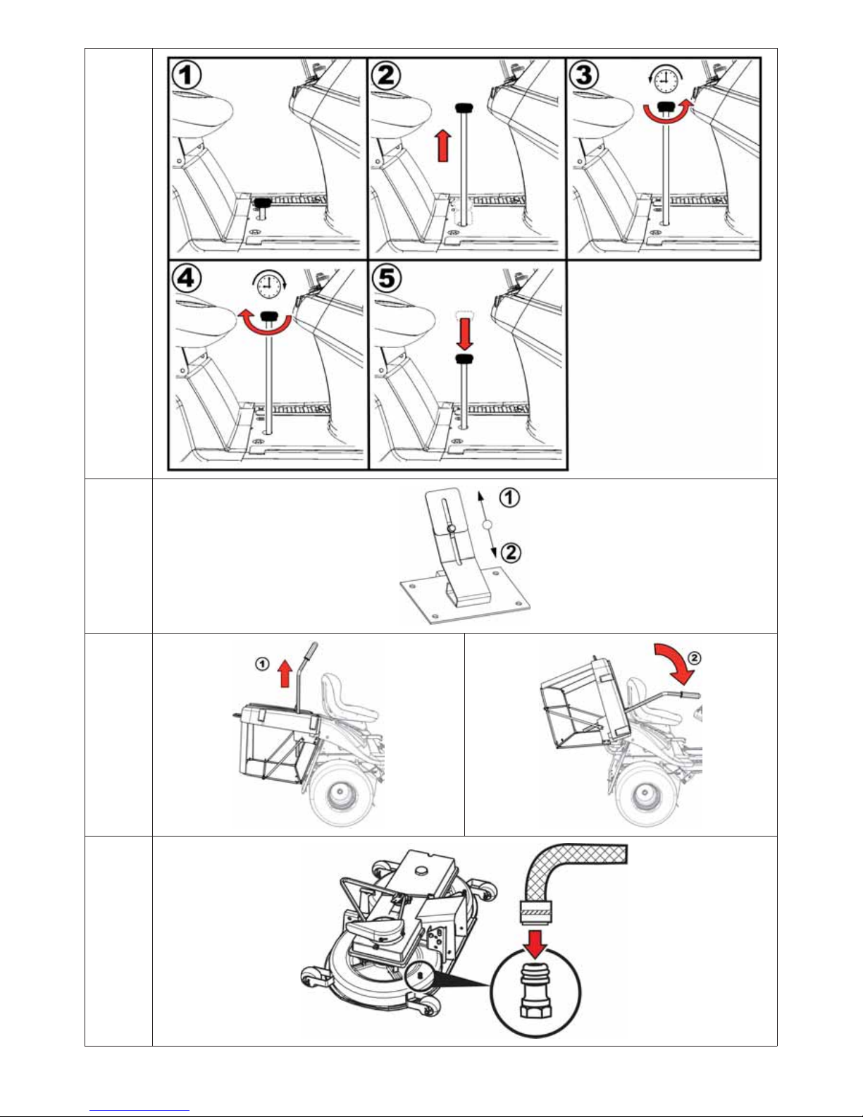
SETTING THE LEVER TO COLLECT GRASS
4.2.1b
(1) Default state
(2) Lift lever
(3) Turn it to the left (counter-clockwise)
(4) Turn it to the right (clockwise)
(5) The lever will move downward by itself to a position that does not impede work
So that the mulching lid will work correctly, after finishing work, thoroughly clear the mowing
mechanism and discharge tube of clippings and contaminants.
(9) FORWARD DRIVE PEDAL
This pedal controls the drive wheels and regulates the machine’s forward movement.
The closer to the floor you press the pedal, the faster the machine goes, and
vice versa.
When released, the pedal automatically returns to the neutral position and the
machine stops.
For more details 5.5.
ATTENTION: A forward/backward change in direction is possible only after the
machine has stopped!
(10) BACKUP PEDAL
This pedal controls the drive wheels and regulates the machine’s backward movement.
The closer to the floor you press the pedal, the faster the machine goes, and
vice versa.
When released, the pedal automatically returns to the neutral position and the
machine stops.
For more details 5.5.
A forward/backward change in direction is possible only after the machine has
stopped!
(11) MOWING MECHANISM HEIGHT ADJUSTMENT LEVER
This lever sets the height of the mowing mechanism from the ground.
The lever has 7 working positions for cutting heights from 3 to 9 cm. (type
AJ102 a AJ102 4x4), height 4 to 10 cm (type AJ110) and 3 to 8 cm (type AG
122).
The higher the lever’s position number, the taller the grass will be after cutting.
Page 40

40
When driving the machine without mowing, the lever must be set to 7.
(12) BYPASS LEVER – FREE MOVEMENT OF REAR WHEELS
The bypass lever is for cutting off power to the rear wheels so that the machine can be pushed or pulled
without the engine. Depending on the transmission used, it is located either behind the left rear wheel
or in front of the left rear wheel. It has the following two positions:
Position Rear-wheel drive Use
(0) OFF
When pushing the machine, the
engine idles
(1) ON When driving, the engine is running
Caution! Due to design reasons it is not possible to disconnect the front axle drive on the
AJ 102 4x4 mower – the hydraulic system does not have a bypass valve. This significantly
limits the machine’s movement when the engine is off. The front axle may get overloaded
during such a motion attempt and may be damaged. In the event that the machine has to be
moved with the motor switched off, always push with the front axle lightened!
The by-pass lever is mostly used to bleed the air out of the hydraulic system. Due to the
complicated design, it is best to have such repairs done at an authorised service centre.
The machine must not be used (the gear engaged) when the by-pass lever is in the OFF
position. You may seriously damage the gears!
4.2.2 OPTIONAL CONTROLS
(1) STARTER
For cold starting the engine.
Machines with engines BS15, BS17, KO15, TE17 and HO16 are not equipped
with separate starters.
(2) BUZZER
The buzzer gives off an audible signal when the grass catcher is full.
After the audio signal that the catcher is full, power to the mowing mechanism is not shut off!
Page 41

41
(3) ENGINE HOUR GAUGE
The operational hour counter implicitly displays the total number of motor hours. Press the Mode button
to switch between the following service functions:
TMR 1 - individual trip counter. Zeroing is carried out by
holding down the Mode button for 6 seconds.
OIL CHG - oil change. The function includes two intervals
for an oil change. The first is after the first
5 hours (oil change after the machine has
been run in) and is displayed only once. The
second is after 25 hours (standard oil change).
AIRFILTER SVC - cleaning or changing the oil filter, the interval
is set to 50 hours.
Two hours before the end of the set interval the display will show a message lasting 10 seconds.
At the end of the interval the display will show a message NOW.
Zeroing of any of the above mentioned alarms is carried out by holding down the Mode button for
6 seconds.
- Manipulation of the counter entails loss of warranty; the hours of movement clock is fitted
with a protective seal.
- If the hours of movement clock is out of action, inform your service agency immediately.
(4) CRUISE CONTROL
The cruise control is used only on long, straight drives. Cruise control must be turned off before any
change in direction.
Cruise control is on only when the ignition is on.
The cruise control can be turned off by stepping on the pedal or shutting off
the switch.
(5) GRASS CATCHER TILT SWITCH
This switch automatically tilts the grass catcher up or down in the case of the type with electrical
emptying of the basket).
To lift or release the catcher, the switch must be held down.
As soon as the grass catcher is at the up or down end position, immediately
release the switch. Doing otherwise can cause electrical failure.
(6) AXLE LOCK PEDAL
This pedal is used only when necessary and only when driving directly forward.
Pressing the pedal downward engages the lock.
Releasing the pedal automatically disengages the lock.
Never use the axle lock when you change driving direction. Otherwise, you may
seriously damage the transmission!
Page 42

42
5. OPERATING THE MACHINE
Good information to know before starting your mower for the first time:
The mower is equipped with safety contacts that are triggered:
- by a switch located below the seat
- a switch mounted in the grass catcher or deflector
- the grass catcher fill switch
- the brake pedal switch
The engine automatically stops if the operator leaves the seat and the machine is not
secured by the parking brake.
The engine can be started only when the mowing mechanism is turned off and the grass
catcher or deflector is installed and the brake pedal is pressed. The deflector prevents
clippings from entering the intake tube to the grass catcher.
5.1 INSPECTING BEFORE STARTUP
Before starting the mower, check the following:
The engine oil level ( 3.4.1)
The battery status ( 3.4.2)
The fuel level ( 3.4.3)
The tyre pressure ( 3.4.4)
5.2 STARTING THE ENGINE
a) Step on the brake pedal.
b) Set the mowing mechanism height lever to position “7”.
c) On motorized machines, open the fuel cap (only on machines with 15.5-hp BS15 engines).
d) Set the accelerator lever as follows:
- On machines with 2-cylinder engines, to the “MAX” position
- On machines with 1-cylinder engines, to the “STARTER” position
e) Pull out the starter (only on engines with 16 hp or more)
f) Turn the key to the “Start engine” position to turn on the ignition. Let go of the key after starting. The
key will automatically return to the “Ignition ON” position.
As soon as the engine turns over, let go of the ignition key. The starting time must not
exceed 10 seconds. Otherwise the switch may be damaged.
Never use fixed external starters to start the machine. This could damage the
electrical wiring. It is possible to connect a higher capacity 12V battery.
g) Plug in the starter (only on machines with 2-cylinder engines)
h) Slowly move the accelerator lever to “MIN” position.
Let the engine run for a few minutes before engaging the mowing mechanism.
- Never let the engine run in a closed or badly ventilated area. Exhaust gases can endanger
your health.
- Keep your feet, hands and loose clothing away from exhaust and moving parts.
Page 43

43
5.3 SHUTTING OFF THE ENGINE
a) Move the fuel control lever to the “MIN” position.
b) If the mowing mechanism is turned on, shut it off by pressing the switch downward.
c) Shut off the engine by turning the key to the “STOP” position and remove the key from the ignition.
If the engine is too hot, let it idle for a while.
- Never shut the engine off just by leaving the driver seat. Leaving the key in the
ignition in “ON” position may damage the electrical system.
- Always turn the key to the “OFF” position and remove it from the ignition. This
prevents children and unauthorized persons from starting the machine.
- Before turning off the ignition, slow the engine to idle in the case of self-ignition. Not
doing this can damage the engine and exhaust.
- Never disconnect the battery cables while the motor is running! This could damage
the motor regulator.
5.3.1 LEAVING THE MACHINE WITH THE ENGINE RUNNING
If you want or need to leave the machine for a while (to remove obstacles, etc.) and you intend to continue
work afterward, you can dismount the machine and leave the engine running. This conserves the
battery.
Conditions for dismounting the machine with the engine running:
the mowing mechanism is off
the fuel control lever is in the “MIN” position
the gear is in neutral and the hand brake is activated (the brake indicator light is on)
5.4 TURNING THE MOWING MECHANISM ON AND OFF
5.4.1 TURNING THE MOWING MECHANISM ON
Move the accelerator lever to “MAX” position.
Use the mowing mechanism height lever to set the mechanism’s working position and thereby the
cutting height.
Set the mowing mechanism switch to “ON”.
Conditions for turning on the mowing mechanism:
- the driver is sitting on the driver seat
- the mown grass container or the deflector or tunnel opening cover is in place
- the AUT/MAN switch (optional equipment) is in the “AUT” position and the basket is empty
- the AUT/MAN switch (optional equipment) is in the “MAN” position
5.4.2 TURNING THE MOWING MECHANISM OFF
Shut off the mowing mechanism by pressing the switch downward.
- If the driver leaves the seat, the engine will stop automatically and this will also stop the
blades from revolving.
- However, never shut off the mowing mechanism just by leaving the seat. If you don’t switch
the ignition key from “ON” to “STOP”, part of the electrical system is still charged and this
can result in damage.The engine hour gauge also remains active.
Page 44

44
5.4.3 SETTING THE HEIGHT OF THE MOWING MECHANISM
If you want to set the mowing mechanism higher from the ground, move its
lever upward.
If you want to set the mowing mechanism closer to the ground, move its lever
downward.
- Position “1” is used for duplicating uneven terrain. Do not use this height setting permanently,
because it will wear out the mowing mechanism’s parts faster.
- The mowing mechanism is equipped with four travel wheels that lift the frame on uneven
terrain and thereby protect the blades from damage.
- If you want to reduce the control force that lifts the mowing mechanism on an AG122
machine, change the auxiliary spring attachment to the left side. The factory default
settings are:
5.4.4 BALANCING THE MOWING MECHANISM
For best mowing results, the mowing mechanism must be set to the correct height. The adjustment
process is explained in chapter “6.3.7 MOWING MECHANISM - INSPECTION AND ALIGNMENT” of this
manual.
5.5 DRIVING THE MACHINE
General warning before driving:
Make sure the parking brake is disengaged. The parking brake lever must not remain in position “2”
( 4.2). The parking brake automatically releases when the service brake pedal is pressed.
The bypass lever must be set to position “1”, i.e., the bypass must be turned off.
When driving toward the mowing area, the mowing mechanism must be turned off and set to
the highest position, i.e., the mowing mechanism’s height adjustment lever must be in position “7”.
When driving over an obstacle mor e than 8 cm high (curbs, etc.), ramps must be used to prevent
damage to the mowing mechanism and transmission.
Avoid colliding the front wheels hard with solid obstacles. This can damage the front axles,
especially at high speeds.
5.5.1 DRIVING FORWARD/BACKWARD
Slowly move the accelerator lever to “MIN” position. This reduces engine RPM.
Slowly depress the accelerator pedal according to the desired driving direction (forward or reverse).
Caution! Pressing the pedal quickly can cause an accident!
Page 45

45
- A forward/backward change in direction is possible only after the machine has
stopped. Not stopping the machine can damage the transmission.
- Never use the accelerator pedal and the brake pedal at the same time. This can
damage the transmission.
5.5.2 STOPPING
Stop the machine’s movement forward/backward by gently letting up on the accelerator pedal and
then pressing the brake pedal.
When pressing the brake pedal while the cruise control is active, the accelerator pedal
automatically moves to the neutral position. Braking distance is less than 2 m.
5.5.3 DRIVING AND MOWING SPEED
It is generally true that the wetter, the higher and the thicker the grass, the lower the speed
you should drive at. At too high a vehicle speed or under a heavy load, the blade RPM drops, reducing
cutting quality, and the removal tube may clog. Under such conditions, always set the engine to
maximum RPM.
If the grass is very tall, it has to be cut more than once. Do the first cut at maximum height or at
a smaller row width. Do the second cut at the desired height.
In the event of mulching using the 110 cm mowing mechanism, it is necessary to precisely adapt the
speed to the height of the mulched growth in view of the considerable motor load at this speed! The
higher the grass, the lower the speed of travel.
We recommend cutting lengthwise or crosswise. Overlapping rows makes the blades more effective
and improves the appearance of the mowed area.
When riding on an uneven surface, the driving speed may vary.
Recommended driving speeds by condition:
State of growth Recommended speed
Tall, thick and wet 2 km/h
Ordinary conditions 3 – 5 km/h
Short, dry grass < 5 km/h
Riding with the mowing mechanism off < 8 km/h
5.5.4 DRIVING ON A SLOPE
Mower models AJ102, AJ110 and AG122 can work on slopes
up to 10° (17%), when using the 4 x 4 drive, tye slope must
not exceed 15° (27%).
When working on a slope, the following principles must be
observed:
Be extra careful when riding on a slope.
Always drive at a slower speed.
Drive only perpendicularly to the contour line, i.e., up and
down. A ride in the direction of the contour is possible
subject to increased care when turning the machine. Avoid
riding along the contour whenever possible.
When turning, take care that the higher wheels do not ride
over an elevated obstacle (stone, tree root, etc.).
Drive more slowly downhill and over obstacles. Take extra
care when turning on slopes or hills.
When stopping the machine on a slope, always use the
parking brake.
Right
Wrong
Page 46

46
Overloading the machine while driving on a slope more than 10° (15°) can damage the
transmission.The manufacturer is not responsible for such damage.
5.6 EMPTYING THE GRASS CATCHER
The grass catcher fill level is signalled by the basket fill lid. The basket fill can be regulated
using the sliding parts of the lid (lengthening or shortening of the arm).
(1) Sliding part pulled out = minimal basket fill
(2) Sliding part pushed in = maximum basket fill
5.6a
Emptying process:
Drive the machine to the place where you want to empty the grass catcher. Stop the machine and set
the brake. If it is on a slope, use the parking brake.
Shut off the mowing mechanism by pressing the switch downward.
If the machine has an AUT/MAN switch, leave it in the “AUT” position.
Set the accelerator lever to the “MIN” position.
On machines with hand-lifted and -tilted catchers:
Slide the catcher’s lifting lever completely up (1) and by tilting it (2) empty the catcher. Let
it empty freely, gradually loosen it and tilt it back.
5.6b
On machines with mechanically lifted and tilted catchers:
Press the catcher’s emptying switch to the “LIFT” position and hold it down until the catcher has risen
all the way. After the position is reached, let up on the switch and wait for the catcher to empty. Then
press the switch back to the “START” position and hold it down until the catcher has tilted all the way.
After the position is reached, let up on the switch.
After tilting the catcher to the basic position, turn the mowing mechanism on using the lever switch.
6. MAINTENANCE AND ADJUSTMENTS
Proper, regular maintenance and inspection of the machine helps extend the mower‘s life and problemfree operation. Worn-out or damaged parts must be replaced in a timely manner. Always use original
replacement parts. Other replacement parts can damage the machine and endanger the health of the
driver and other persons and void warranty claims. To order replacement parts, always contact the
manufacturer or an authorized service facility.
Page 47

47
6.1 OVERVIEW OF INSPECTION AND MAINTENACNE
Activity
INTERVAL
Regular maintenance Maintenance by hours of use Seasonal maintenance
Before
each use
After the
first 2
hours
After the
first 5
hours
After each
use
Monthly 25 50 100
Before
mowing
season
After
mowing
season
(st or ing th e
machine)
Check the oil
(transmission,
engine)
Change the engine
oil
1,2
Fuel filter change
Battery
maintenance
(che c k ing
electrolytes and
cleaning)
Inspect and adjust
the drive belt
4
Check the brake
control
Inspect tyre
pressure
Check cable
connections (loose
connectors)
Clean the mowing
mechanism
Check screw
connections
Check tension of
toothed belt that
rotates the blades
4
Check the V-belt
tension on the
mowing mechanism
drive
4
Check and adjust
play of front axle
and steering
Check operation of
safety switches and
devices
Check and adjust
engine operation,
transmission and
electromagnetic
connectors
Check and maintain
air filter, spark
plugs, and change if
necessary
1,2
Check mowing
mechanism (play,
shaft alignment,
inspect and sharpen
blades)
3
Notes to chart:
1 = Change the oil more often if the lawn mower has worked with a higher load or in outdoor temperatures of 35°C or higher.
2 = Check more often if the machine operates in a dusty environment.
3 = Check more often if the machine works in a sandy environment.
4 = Check more often if the a new belt has been installed.
Page 48

48
6.2 DAILY INSPECTION AND MAINTENANCE
- Before beginning any maintenance or service, familiarize yourself again with all instructions,
restrictions and recommendations in this manual.
- Always remove the key from the ignition and disconnect the spark plug cables before
performing any cleaning, maintenance or repairs.
- When working, always wear appropriate work clothes and shoes. When handling the cutting
blades or during activities that pose a cutting risk, wear appropriate work gloves.
- Avoid spilling fuel, oil or other hazardous substances.
Dispose of used oil, fuel or other hazardous substances according to applicable environmental
protection laws.
6.2.1 BEFORE STARTING WORK
TYRE PRESSURE INSPECTION
Inspect the tyre pressure regularly and make sure it meets requirements. Maintaining the specified
pressure is important to even mowing. Other pressure values can hamper driving and even result in loss
of control.
The air pressure in the front and rear tyres must be within the range of 80 - 140 kPa, and the difference
between the individual tyres can be ± 10 KPa.
CONTROL OF ENGINE OIL LEVEL
Place the lawn mower mower on a level surface. Open the bonnet and unscrew the cap of the filling port.
Unscrew the dipstick, wipe it clean, reinsert it and screw it back in. Then unscrew it again and read the
oil level.
The oil level must be between the two marks on the dipstick. If it is not, add motor oil until it reaches
the “FULL” mark.
Further information on checking and adding oil is given in a separate manual provided by the
engine manufacturer.
CHECKING CABLES AND SCREW CONNECTIONS
Visually inspect the state of the cables and manually check tightness of screw connections.
CHECKING BRAKE FUNCTION
Check the brakes for proper operation. Proceed as follows:
Set the machine on a level surface and shut off the engine.
Press the brake pedal and engage the parking brake.
Use the bypass lever to cut off power to the rear wheels.
Try to push the machine forward manually. If the rear wheels turn, brake service is needed. Contact
an authorized service facility that will adjust them.
6.2.2 AFTER FINISHING WORK
MACHINE SETTINGS
After mowing, raise the mowing mechanism to the highest position and shut off power to the rear wheels.
Turn off the ignition, press the brake pedal and use the parking brake to keep the machine in position.
On machines with BS15 (15.5-hp) engines, close the fuel intake.
CLEANING THE MACHINE
Remove all dirt and clippings from the tractor’s surface, the removal tube and the mowing mechanism.
Thoroughly clean the grass catcher’s fabric bag. If grass is stuck to it, the machine can’t fill the grass
catcher as well.
WASHING THE MACHINE
Before washing, park the machine on an appropriate level surface.
Page 49

49
Grass catcher:
- remove the grass catcher from the machine, wash it and let it dry.
Plastic parts:
- clean with a sponge and soapy water.
Mowing mechanism:
- wash from inside, including internal parts and removal tube.
- slip a hose of an appropriate diameter onto the mechanism’s cover extension. Start the
engine, start the mowing mechanism and rinse the mowing mechanism for 10 minutes.
This rinse must be performed after every mowing.
6.2.2
Avoid washing with water near electrical equipment on the instrument panel, battery, etc.
6.3. REGULAR INSPECTION, MAINTENANCE AND ADJUSTMENTS
6.3.1 BATTERY
Correct, regular maintenance increases the life of the battery. You should therefore check it according
to the battery manufacturer’s instruction manual.
Keep the battery contacts clean. If they get dirty or corroded, clean them according to the manufacturer’s
instructions. Interruption of the circuit caused by the oxidation of the contacts may lead to the
malfunction of the recharging function of the motor!
Regularly check the electrolytes. The level should be between the MIN and
MAX marks. For filling the electrolytes, use only distilled water.
A drained battery must be charged as soon as possible. Otherwise the cells may be irreversibly
damaged.
The battery must always be charged before:
- first use
- during a long storage period
- before operation after a long storage period
If the battery needs to be changed, always use a battery of the same size and model.
Further information on checking and maintaining the battery is given in a separate manual
provided by its manufacturer.
6.3.2 ENGINE
CHANGING THE OIL
Before changing the oil, prepare a container of at least 2 litres. For all
oil to drain from the engine, we recommend tilting the machine (such
as with wooden blocks) on the opposite side from the drain plug. Drain
the oil while it is still warm.
Remove the oil filler cap so that the oil will drain better and faster.
Unscrew the drain plug and let the oil drain completely into the
prepared container.
Screw the drain plug back in, pour in the right amount of the specified
oil ( Engine operation manual) and close the oil filler cap.
Use the dipstick to check the oil level. If necessary, add oil to the
proper level.
Page 50

50
Further details on checking and adding oil, including information on the type and amount of
oil, are given in a separate manual provided by the engine manufacturer.
- If you come into contact with used oil, we recommend thoroughly washing your hands with
soap and water.
- Dispose of used oil according to environmental protection rules. Properly transport the oil in
a closed container to a used oil collection point. Never discard used oil with ordinary refuse,
and do not pour it down the sewer, into garbage or into the earth.
AIR FILTER MAINTENANCE
Never let the engine run without the air filter. This will wear out the engine quickly.
Maintain the air filter according to the instructions given in the manual provided by the
engine manufacturer.
SPARK PLUG MAINTENANCE
For perfect engine operation, the spark plug must be correctly installed and cleaned of deposits.
- Always use only the plug specified by the engine manufacturer!
- If the engine has been running shortly before inspection and replacement, the spark plug
is very hot. Be careful not to burn yourself.
Disconnect the spark plug cable and remove the plug with a spark plug
wrench.
Visually check the appearance of the plug. If the plug is visibly very worn or
has a broken or scaled insulator, it must be replaced.
If the plug is soiled or just mildly worn, it must be carefully cleaned with an
appropriate (copper) wire brush.
Use a gauge to set the spark plug gap ( Engine operation manual).
After maintenance or replacement, properly tighten the plug. An improperly
tightened plug gets very hot and can cause serious engine damage.
Inspect, maintain and replace the spark plug according to the instructions given in the
manual provided by the engine manufacturer.
CHANGING THE FUEL FILTER
Never let the engine run without the air filter. This will wear out the engine quickly.
Change the fuel filter according to the instructions given in the manual provided by the
engine manufacturer.
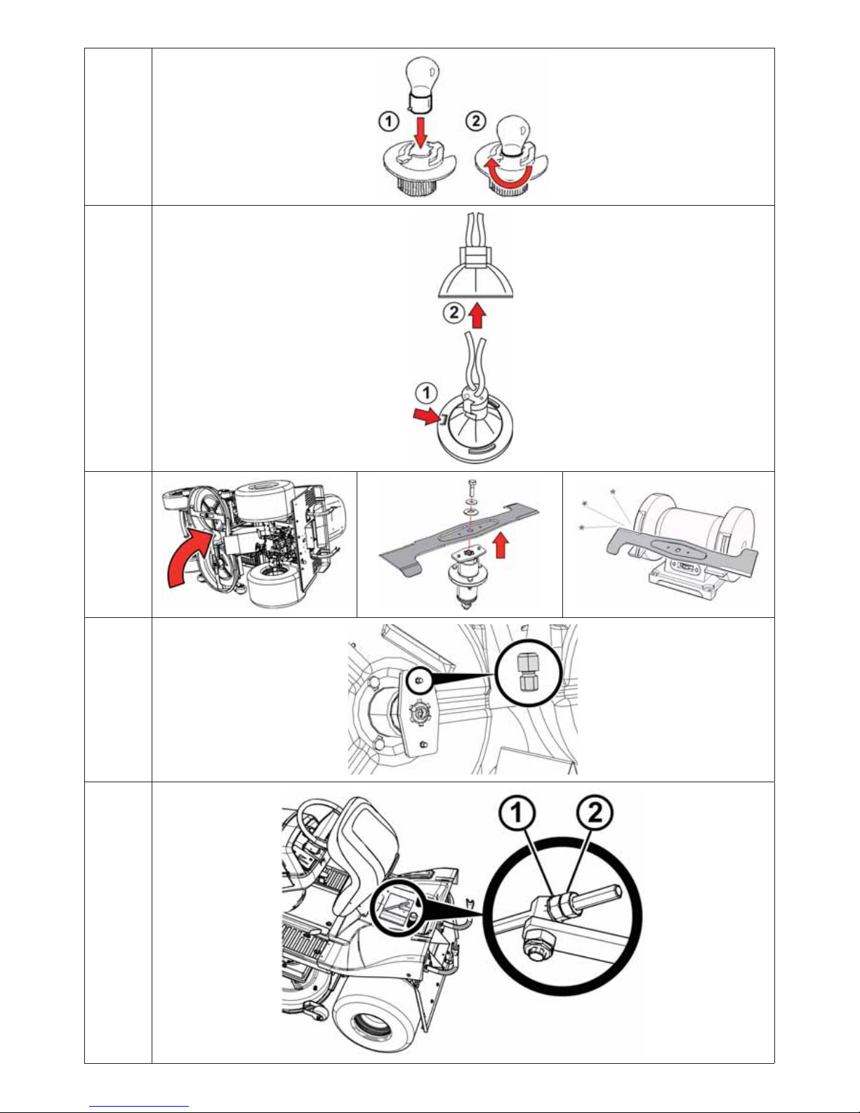
6.3.3 REPLACING LIGHT BULBS
Depending on the model, light bulbs are installed either in a bayonet socket or a reflector, and they are
accessible by opening the bonnet.
Types of light bulbs:
Type of bulb: Socket/reflector: Replace with:
K20, 12V / 10W Bayonet socket
K20, 12V / 10W or equivalent from
another manufacturer
Halogen light bulbs, 10W / 12V
M Light reflector, model HLRG-510F,
diameter 51 mm (screw cap GU5,3)
M light model HSS-510 or equivalent
from another manufacturer
Halogen light bulbs, 10W / 12V
(hood with four headlights)
M Light reflector, model HLRG-35/520F,
diameter 35 mm (screw cap GU4)
M light model HSS-520 or equivalent
from another manufacturer
Halogen light bulbs, 20W / 12V
(hood with two headlights)
M Light reflector, model HLRG-35/520F,
diameter 35 mm (screw cap GU4)
M light model HSS-520 or equivalent
from another manufacturer
Page 51

51
When replacing a light bulb that has a bayonet simply turn (loosen) the burnt-out bulb
and remove it from the socket. Then insert a new bulb into the socket and turn it until it
locks.
6.3.3a
When replacing the halogen light bulbs first press the tab (1) and slide the bulb out of
the socket (2). For installation proceed in the reverse sequence.
6.3.3b
6.3.4 REPLACING FUSES
If a fuse fails, the engine will immediately quit, the mowing mechanism will stop, and all gauges on the
instrument panel will go dark. In that case, it is necessary to seek out the blown fuse and replace it with
a new one. Never replace a faulty fuse with one of a higher current rating!
The fuses are located on the steering column and can be accessed by lifting the cover and removing the
protective fuse cover.
Remove the fuse and insert a new fuse of the same rating as the original one, i.e., 15A or 5A. If the
engine or the mowing mechanism cannot be started after fuse replacement, contact your authorized
service centre.
Some models of machines are equipped with a central electrical installation distribution box. Never
tamper with this distribution box, except to change fuses.
6.3.5. RAISING THE MACHINE
If you want to raise the lawn mower, use a jack and supports.
Proceed as follows:
Place the jack under the transmission on the rear axle and raise the machine’s rear end.
Insert two supports under the ends of the axle inside the rear wheels.
Lift the front end of the machine and insert two supports under each end of the front wheel pins.
Never tilt the machine to the side where the engine’s carburettor is located. This could make
oil seep into the air filter!
6.3.6 MOWING MECHANISM - SHARPENING AND CHANGING BLADES
SHARPENING BLADES
The cutting blades must be sharp, statically balanced and straight. Blunt, improperly sharpened or
damaged blades uproot grass, damage the lawn and don’t allow the catcher to collect grass properly.
- Never repair a deformed or otherwise damaged blade. Always replace it
immediately.
- Whenever handling the blades, wear solid work gloves.
Sharpening process:
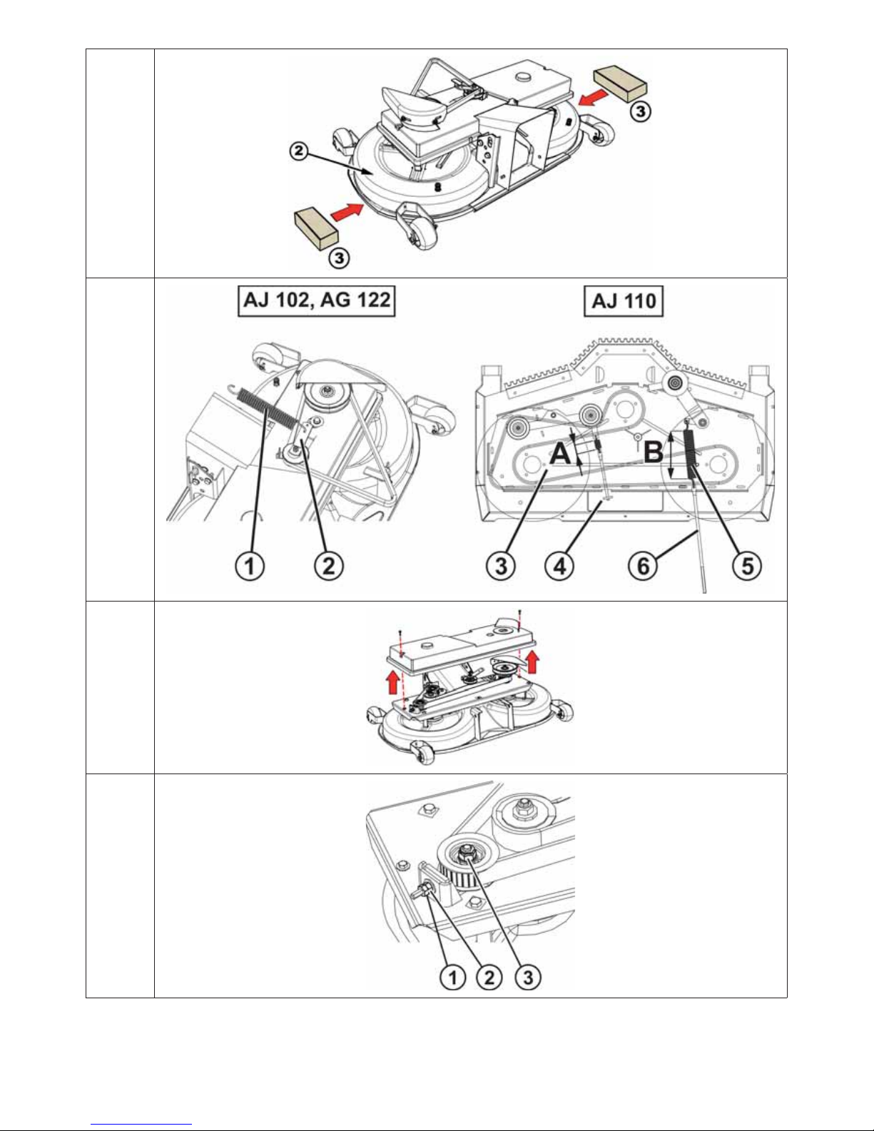
Remove the grass catcher, tilt the machine to the right side, and place appropriate pads
under it. We recommend having another person help, in order to avoid injury and damage
to the machine.
Unbolt both blades and clean them. If the machine is equipped with TRIPLEX blades,
remove each blade from the holder.
First sharpen the blades with a grinder, and then with a file. For TRIPLEX blades, grind
each separately.
In the case of a three rotor 110 cm mowing mechanism every pair of knives is secured by
three screws (the knives are not equipped with shear pins).We recommend that the knives
should be marked before disassembly to ensure absence of problems on reassembly.
6.3.6a
Do not sharpen the blades directly on the mowing mechanism.
After sharpening, do not reinstall the blades yet, but check their balance. See the procedure below.
Page 52

52
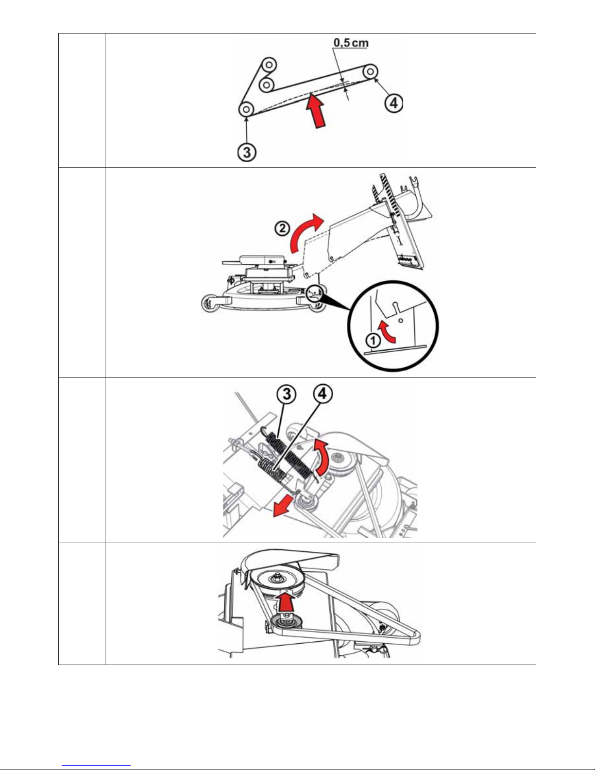
Before reinstalling the blades, check the shear pins that protect the mowing mechanism
from damage. If the shear pins are damaged, replace them immediately. Replacement pins
come with the machine.
6.3.6b
After checking the balance and the shear pins, bolt the blades back on. When installing, make sure
the blades to not face upward inside the mowing mechanism cover. Do not switch the left one with the
right one. The right blade has leftward threads.
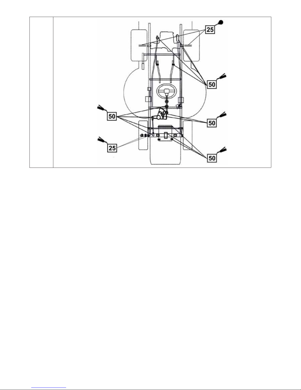
Carefully tighten the blades’ mounting bolts using a torque wrench set to ±3 Nm. This torque is
reached at exactly the moment when the tangential spring under a blade’s mounting bolt is completely
compressed. After that, do not tighten the screw further.
BALANCING THE BLADES
Use great care when aligning and balancing the blades. Vibration from misaligned and unbalanced
blades can damage the engine or mowing mechanism.
When balancing, insert a screwdriver into the centring hole
and place the blade in horizontal position. If the blade stays
in this position, it is balanced. If one of the ends of the blade
is heavier, grind this side until it is balanced. When grinding
for balance, do not shorten the blade! The maximum static
balance is 2 g.
If you are not sure of the procedure, contact your authorized service centre, where they will
gladly advise you.
REPLACING BLADES
If the blades have been damaged by frequent use, they cannot be properly sharpened and must be
replaced. Proceed as follows:
Remove the grass catcher, tilt the machine to the right side, and place appropriate pads under it. We
recommend having another person help, in order to avoid injury and damage to the machine.
Unbolt both blades. If the machine is equipped with TRIPLEX blades, remove each blade from the
holder.
Before installing the new blades, check the shear pins that protect the mowing mechanism from
damage. If the shear pins are damaged, replace them immediately.
Check the new blades’ balance. See above.
Bolt the new blades on. When installing, make sure the blades do not face upward inside the mowing
mechanism cover. Do not switch the left one with the right one. The right blade has leftward threads.
Carefully tighten the blades’ mounting bolts (applicable to machine types AJ102, AJ102 4x4
and AG122) using a torque wrench set to ±3 Nm. This torque is reached at exactly the moment when
the tangential spring under a blade’s mounting bolt is completely compressed. After that, do not
tighten the screw further.
In the case of machine of type AJ110, the screws are tightened with current tightening moments
M8 – 24 Nm, M10 – 48 Nm.
- As soon as the blades meet a hard object, stop the engine immediately and check
them! The shear pins may be damaged or severed.
- Whenever handling the blades, wear solid work gloves.
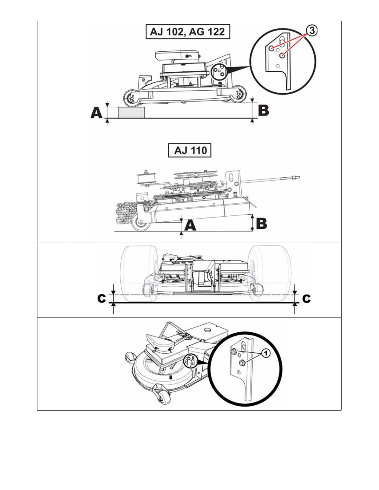
6.3.7 MOWING MECHANISM - INSPECTION AND BALANCING
For best mowing results, the mowing mechanism must be set to the correct height from the ground, and
each side of the mechanism must be level.
Before adjustment:
Place the machine on a perfectly level surface, inflate all tyres to the rated pressure (80 - 140 kPa,
± 10 kPa between the individual tyres) and secure the whole machine against movement (e.g.,
with an appropriate wedge, etc.).
Set the mowing mechanism height lever to position 2.
Page 53

53
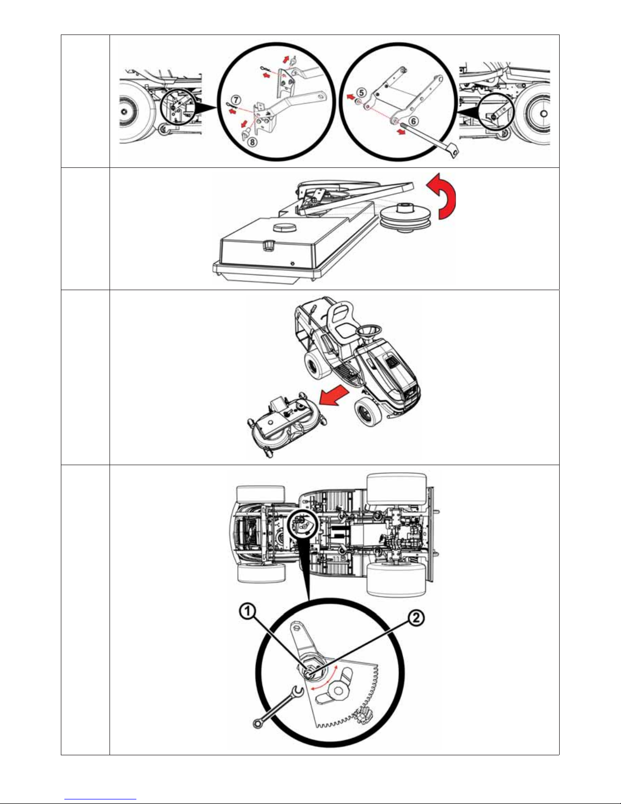
ADJUSTING THE HEIGHT OF THE MOWING MECHANISM IN THE DRIVING DIRECTION
(applicable to machines AJ102 AJ102 4X4 AND AG 122)
Check the height of the front edge A of the mowing mechanism above the ground. This
must be 13–15 mm and the edges on both sides must be the same.
If the height is different, tilt the seat up and, depending on the model of machine, remove
either the battery compartment or the tool compartment. Loosen the lock nut (2) and turn
the nut to adjust the height (1). After setting the correct height, don’t forget to tighten the
nut (2).
6.3.7a
As soon as the front edge is at the correct height, place an appropriate washer of the
corresponding height underneath it.
Check the height of the mowing mechanism’s rear edge B. It must be 10-13 mm higher
than the front edge, i.e., 23-25 mm above the ground. If the height is incorrect, adjust it
by loosening the screw (3) on the mowing mechanism frame. Then retighten the loosened
nuts and bolts to 55 – 65 Nm.
6.3.7b
HEIGHT OF ADJUSTMENT OF MOWING MECHANISM IN THE DIRECTION OF THE RIDE
(applies to AJ110 machines AJ110)
Control the height above ground of the front edge A of the mowing mechanism (measured
on the side of the cover), which must be 35–40 mm and must be the same on both sides
of the edge.
Control the height of the rear edge B of the mowing mechanism. This must be 5-8 mm
higher thanthe front edge.
6.3.7b
BALANCING THE MOWING MECHANISM SIDEWAYS
The mowing mechanism must be properly set on the sides (
6.3.7c). The left and right sides of the
mechanism must be horizontal.
Loosen the bolts on the left and right sides of the adjustment plate (1).
6.3.7d
Under the mower mechanism cover (2) place inserts of identical height (3) (e.g., wood
panels, etc.) and use them to balance the cover such that the left and right sides are equal
distance from the ground. The difference between the left and right sides of the cutting
mechanism should be no more than 5 mm.
Then retighten the loosened nuts and bolts to 55 – 65 Nm.
6.3.7e
If you are not sure of the procedure, have a service centre do this for you.
6.3.8 MOWING MECHANISM - INSPECTION AND ADJUSTMENT OF THE V-BELT
With time, stress loosens the mowing mechanism’s drive belt, and it must be tightened. The
belt is tensed by pulleys and springs.
Transfer the spring (1) to the second hole in the pulley tensioning lever (2).
In the case of machine AJ 110, stretch the stretching spring (3) of the belt to
A=45 ± 1 mm using the stretching tie rod with nut (4).
Stretch the spring of the mowing mechanism (5) driving belt to B=135 ± 1 mm (in
position 7), once again using the stretching tie rod with nut (6).
6.3.8
6.3.9 MOWING MECHANISM - ADJUSTING THE BLADES’ TOOTHED DRIVE BELT
(Machines AJ 102, AJ102 4x4, AG 122)
Set the mowing mechanism to the lowest position by setting the adjustment lever to
position 1.
Loosen the bolt on the plastic cover on the right side in the driving direction and lift the
cover.
6.3.9a
Page 54

54
Under the metal plate, loosen the nut on the tensioning mechanism with the toothed belt
(3) such that it can turn with mild resistance from the washer under the nut.
Loosen the safety nut (1), turn the nut (2) rightward and check the tension of the toothed
belt.
6.3.9b
The belt is properly tensioned, when exerting 4 kPa of pressure halfway between pulleys
(3) and (4) the belt sags about 0.5 cm.
6.3.9c
To measure the force, use, for example, a standard dynamometer available in stores that
carry them.
Tighten the safety nut (1) of the tensioning device and retighten the nut on the tensioning mechanism
with the toothed belt (3).
Put the plastic cover back on and tighten its mounting bolt.
6.3.10 MOWING MECHANISM - REMOVAL
Set the mowing mechanism to the lowest position by setting the adjustment lever to
position 1.
Slightly raise the grass removal tube (1) and slide it off the two pins welded to the frame
of the mowing mechanism. Then either slide the tube 10 cm to the rear (2) and secure it,
or completely remove it from the machine through the rear plate.
6.3.10a
Remove the spring (3) from the shoulder of the tension pulley and loosen the spring
upward (4).
6.3.10b
Stand on the right side of the machine. Push the tensioner pulley toward the large pulley.
This loosens the V-belt. Then remove the belt.
6.3.10c
Slide the spring pins (7) from both the rear mowing mechanism suspension shaft pin (8).
Screw out the nut (5) from the front shaft pin and pull out the shaft pin (6).
6.3.10d
Use pliers to remove all pins from the mowing mechanism suspension. When pulling them
out, make sure that you don’t injure your hands or fingers.
Remove the V-belt from the pulley of the electromagnetic connector.
6.3.10e
Slowly slide the mowing mechanism to one side of the machine.
6.3.10f
6.3.11 STEERING MAINTENANCE
Regularly check to see that there is no excessive play between the steering rack and pinion.
If there is too much play, reduce it.
6.3.11
Ignoring this maintenance can cause damage to the steering.
How to adjust the play:
Loosen the two M12 nuts (1) on the eccentric bolt.
On the hexagonal eccentric (2) place an appropriate wrench and turn it until the the play
is reduced to the minimum.
Tighten both M12 nuts (1) to 35 - 45 Nm.
Page 55

55
6.3.12 CHECKING AND ADJUSTING THE DRIVE BELT
Regularly check the drive belt tension. The belt is properly tensioned, when exerting 4 kPa
of pressure halfway between pulleys (1) and (3) and the belt sags about 1.5 cm.
If the sag is greater, adjust the tension.
6.3.12a
To measure the force, use, for example, a standard dynamometer available in
stores that carry them.
The positions in the illustration are:
(1) The engine pulley
(2) The guide pulley
(3) The tension pulley
(4) The transmission pulley
Adjust belt tension by tightening the nut on the bolt that tenses the tension spring, and then
finish the adjustment using the bolt (5) on the pulley (2) so that the spring is stretched to a
length of 50±1 mm.
6.3.12b
Do not stretch the belt above this threshold. It can shorten the belt’s life
and even damage the transmission!
6.3.13 REPLACING BELTS
Replacing the drive belt is a relatively demanding procedure and must be entrusted to an authorized
service facility.
6.3.14 REPLACING WHEELS
Before changing one of the wheels, park the tractor on a solid, level surface, shut off the engine and
remove the key from the ignition. Change the wheel as follows:
Raise the machine using an appropriate jack on the side on which the wheel is to be
changed. Set the jack below a solid part of the machine’s frame or on the transmission
arm. Secure the machine below with an appropriate wooden block.
Remove the protective cover from the wheel (front wheels only).
Use an appropriate screwdriver to remove the retaining ring and remove the washer.
Take the wheel off the shaft. For rear wheels there is a spring on the shaft.
6.3.14
When putting the wheel back on, perform the assembly steps in reverse order. Before installing the
wheel, clean all parts, and lightly grease the shaft. Especially for wheels on the rear axle, this greasing
is indispensable for later wheel removal. If the shaft is not greased, later assembly may be
difficult.
When installing a rear wheel, be careful of the mutual position of the spring on the shaft and the groove
in the wheel.
6.3.15 REPAIRING TYRE DEFECTS
The machine is equipped with tubeless tyres. If they are defective, entrust their repair to a professional
tyre service or to an authorized Seco lawn mower service centre.
Page 56

56
6.3.16 MAINTAINING THE HYDROSTATIC TRANSMISSION
Machines AJ102, AJ110 and AG122:
To ensure reliable operation of the transmission, you must maintain the proper oil level. The transmission
filling ports are accessible after removal of the machine’s removal tube (
6.3.10). The prescribed
values are shown in the following chart.
Transmission type Oil type Oil level
TUFF-TORQ K46 SAE 10W-30, API CD at least half the height of the distribution reservoir
TUFF-TORQ K62 SAE 10W-30, API CD lines 5-7 on the distribution reservoir
TUFF-TORQ K664, KXH 10 SAE 5W-50, API CD Between the turns on the filling screw
Machines AJ102 4x4:
To ensure reliable operation of the transmission, you must maintain the proper oil level. The transmission
filling port is under the seat of the mower ( 3.4.5). The prescribed values are shown in the following
chart.
Transmission type Oil type Oil level
TUFF-TORQ K 664
SAE 5W-50, API SG
synthetic oil
according to the level marks in the expansion
tank ( 3.4.5).
KANZAKI KXH 10 N
SAE 5W-50, API SG
synthetic oil
according to the level marks in the expansion
tank (
3.4.5).
If there are problems with the transmission, get immediate help from an authorized service
centre to prevent serious damage.
6.3.17 OVERVIEW OF BOLT TORQUE
Mowing mechanism: Torque
Central blade bolt 30 ± 3 Nm
M12 nuts for the mowing mechanism drive pulleys 45 - 55 Nm
10x25 KL 100 RIPP bolt for the shoulder of the tensioning pulley of the mowing
mechanism drive belt
55 - 65 Nm
Steering:
M8x30 bolt to the steering section 15 - 25 Nm
M12 bolt to the steering section 35 - 45 Nm
Engine:
Bolt to the electromagnetic connector 60 - 70 Nm
Bracket screw for the drive belt tension pulley 25 - 35 Nm
Se lf- loc ki ng nut s mu st b e re plac ed w it h ne w on es d uri ng re mo va l an d re ins ta ll ati on.
6.4 LUBRICATION
Lubricate the machine according to the following schedule.
The bearings of the tensioning pulleys, guide pulleys and mowing mechanism are self-lubricating.
Before storing the machine for an extended time, thoroughly lubricate all areas shown in the schedule.
But particularly the half-axles of the front and rear axles (it is necessary to disassemble the rear
wheels).
Page 57

57
6.4
Symbol Explanation
Grease
SAE 30 oil
Interval in
hours
Apply grease to:
angle joints of the drive connecting rods - remove and lubricate
brake rod bolt - lubricate the rod near the bolt hole
bolt to the mowing mechanism lift rod - lubricate the rod in the area of the bolt hole
angle joints of the steering connecting rods - remove and lubricate
angle joints of the wheel pins - remove and lubricate
front wheel bearings
wheel pins that go through the axle
centre rotary pin of the front axle - through the grease nipple
steering wheel shaft bearing - lubricate
toothed steering segment and eccentric - lubricate
half-axles of the rear wheels
spigots of the wheels of the front axle for the front wheel (machine AJ102 4x4)
rear half-axles for the rear wheel (machine AJ102 4x4)
Use oil to lubricate the rotating points:
axle lock pedal
brake pedal
7. TROU BLES HOO T ING
Never perform a service operation if you do not have the appropriate qualifications and equipment. The
operations below can be performed by the user. Service operations other than those shown here will
void the warranty when performed by the user. The manufacturer is not liable for damages resulting
from the user’s poor execution of prohibited service operations.
Problem Solution
The machine cuts
unevenly
Remove clogged clippings from the underside of the mowing mechanism.
Make sure the blades are sharp and not deformed.
Check the blade tightness.
Check the mowing mechanism’s height adjustment. ( 6.3.7). If it is not correct, readjust it.
Check the tension of the belts ( 6.3.8 and 6.3.9). If necessary, adjust the tension.
Check the blade shaft. If it is damaged or overly worn, replace it.
Page 58

58
Problem Solution
A strip remains
unmowed between the
blade rotors
Check for damaged bearings. Repair or replace, if necessary. When mowing thick grass or
grass with an excessively wet surface, an unmowed strip may remain.The driving speed should
correspond to the right transmission gear for the mowing conditions. The engine should run
with a completely open throttle.
Make sure the blades are sharp and not deformed. Replace the blades, if necessary.
The mowing
mechanism pulls the
turf
Check the tension of the belts ( 6.3.8 and 6.3.9). If necessary, adjust the tension.
Check for damaged bearings. Repair or replace, if necessary.
Check the mowing height and adjust it, if necessary. Turf is often pulled on uneven terrain.
Check to see if the blades are warped. Replace the blades, if necessary.
The mowing
mechanism does not
eject the grass
Remove clogged clippings from the underside of the mowing mechanism. Under wet conditions,
the removal tube and the underside of the mowing mechanism’s exit port can be clogged with
grass. Do not cut wet grass.
The driving speed should correspond to the right transmission gear for the mowing conditions.
The engine should run with a completely open throttle. When mowing tall grass, first mow
once at a high adjustment and then again at normal height. Abide by the information in chapter
5.5.3.
Check the tension of the belts ( 6.3.8 and 6.3.9). If necessary, adjust the tension.
Especially after replacing blades, make sure that the blade is installed correctly.
The mowing
mechanism’s drive belt
stops during operation
The mowing mechanism’s drive belt may be damaged if it jumps out of the pulley during
operation. If the belt still jumps out after trying the following steps, it must be replaced.
Check the belt tension ( 6.3.8). If necessary, adjust the tension.
Check the belt guide.
Check the mowing height, and adjust it if necessary.
Check to see if belt movement is being impeded by a foreign object. If it is, remove the object.
Double check all pulleys. A bent or broken pulley can cause problems. Replace it, if necessary.
Check the inner surface of the pulley on the engine. If it is rough or has cracks, the pulley
should be replaced.
Check for worn-out parts in the tensioning mechanism, and replace them if necessary.
The mowing
mechanism’s drive belt
slips
If the grass is too tall or wet, the mowing mechanism’s belt can slip. Check to see if the belt is
worn out. If it is, change it.
Check the belt tension ( 6.3.8). If necessary, adjust the tension.
Check the tension spring of the turnbuckle mechanism of the mowing belt.Replace the pulled
or damaged spring.
The mowing
mechanism’s drive belt
wears excessively
Check all areas of the pulley guide. Check to see if belt movement is being impeded by a
foreign object. If it is, remove the object.
Check the pulleys, and if they are damaged, replace them.
Check the mowing height, and adjust it if necessary.
Check the belt tension ( 6.3.8). If necessary, adjust the tension.
Set the blades in
motion
Check to see if the belt is worn out or damaged. If it is, replace it. If it is loose, tighten it.
Check the spring on the tensioning mechanism. Replace the broken or damaged spring.
Check to see if belt movement is being impeded by a foreign object. If it is, remove the object.
The blades stop late
Check the belt tension ( 6.3.8). If necessary, adjust the tension. If the belt cannot be
tightened further due to considerable wear, replace it.
Check to see if belt movement is being impeded by a foreign object. If it is, remove the object.
Check the operation of the electromagnetic connector to see if it shuts off properly. If it
malfunctions, have it repaired or replaced by an authorized service facility.
When the mowing
mechanism’s drive
is turned on, the
belt shows extreme
vibration
Check the blades to see if they are uneven or warped, and also check to see if they are
balanced. If they are deformed, replace them.
Check to see if the belt has burnt surfaces or irregularities that may lead to vibration. Replace
the damaged belt.
Check to see if the blades are worn or damaged. Replace them, if necessary.
Check the operation of the electromagnetic connector to see if it turns on properly. If it
malfunctions, have it repaired or replaced by an authorized service facility.
Check the inner surface of the pulley on the engine. If it is rough or has cracks, the pulley
should be replaced.
Check to see that no grass is lodged under the mowing mechanism. If there is any, remove it.
Check to make sure there is no defect in the engine mount. If necessary, tighten or replace
the bolts.
Check the belt tension ( 6.3.8). If necessary, adjust the tension.
Page 59

59
Problem Solution
The driving belt is
sliding.
Check the drive belt tension ( 6.3.12). If necessary, adjust the tension.
Check to see if the belt is damaged or worn.
Check to see if the drive coupling mechanism is blocked by a foreign object. If it is, remove
the object.
Check to see if the engine or transmission pulley is damaged. If necessary, replace it.
The drive belt squeaks.
Check the drive belt tension ( 6.3.12) and the brake operation. If necessary, adjust the
belt tension. If the brake operation is not in order, have an authorized service centre adjust it.
The drive belt jumps
out during operation
Check the drive belt tension ( 6.3.12). If necessary, adjust the tension.
Check the belt guide. If necessary, adjust it.
Check for damaged pulleys. Replace them, if necessary.
Check the space between the drive coupling mechanism. If there are deviations, the coupling
pulley support may be bent. Replace it if necessary.
The machine does
not move when the
accelerator is pressed
Check the drive belt tension ( 6.3.12). If necessary, adjust the tension.
Check the engine and transmission pulleys for sheared or cut grooves. Replace if necessary.
There is a lot of
vibration while driving
Check for damaged or deformed pulleys. Replace them, if necessary.
Check to see if the drive belt has burnt areas or other irregularities. Replace it, if necessary.
Check the drive belt tension ( 6.3.12). If necessary, adjust the tension.
Check the balance of the mowing blades. Replace or rebalance them, if necessary.
The steering slips or is
loose.
Check to see if there is too much play between the segment and the pinion. If there is, adjust
the toothed segment. Check for wear to the ball joints. If necessary, replace the joints.
The engine doesn’t run
Check to see if there is fuel in the tank.
Check to see if the designated engine start-up procedure has been followed ( 5.2)
Check the fuse. If necessary, replace it.
Check to see that the battery’s pole voltage is 12 V. On a new machine, make sure the battery
has been activated and charged. On new machines, remove the spark plugs and make sure
that the oil hasn’t accumulated in the cylinder due to improper handling.
Check to see that all wire connectors are in order and that the electrical system’s switches are
operational.
Test the engine exactly according to its manufacturer’s user manual. Have the machine’s
electrical system tested at a professional workshop.
Engine turns but won’t
fire
Check to see if the designated engine start-up procedure has been followed ( 5.2). Check
to see if the fuel in the tank is clean.
Check to see if the fuel filter is clogged.
Check to see if the fuel cap is open (only on BS15.5 engines).
Make sure that the fuel lever is in the “STARTER” position.
Test the engine exactly according to its manufacturer’s user manual. Have the machine’s
wiring and switches tested at a professional workshop.
The machine can’t be
pushed, or only with
difficulty
Check to make sure the bypass lever is in the “0” position.
There is a whistling
sound while driving
Check the belts, and the guide and tensioning pulleys. If the problems persist, seek out an
authorized service centre.
7.1 ORDERING REPLACEMENT PARTS
We recommend using original replacement parts, which guarantee safety and interchangeability. Always
order replacement parts through an authorized dealer or service organization that is informed about the
current technical changes to the products during production.
For fast, precise identification of the replacement part you need, always include the serial number on
the order form. You will find this number on inside cover of this publication. Also include the production
year, which is on the manufacturer’s label below the driver seat.
7.2 WAR R A NT Y
The warranty requirements are described on the warranty card, which is supplied with your machine at
the dealer.
Page 60

60
8. END-OF-SEASON MAINTENANCE AND STORAGE
After the end of the season or if you will not be using your machine for more than 30 days, prepare it
for storage as soon as possible. If fuel remains in the fuel tank for more than 30 days, it may form a
sticky sediment, which may hurt the carburettor and cause poor engine performance. Therefore empty
the fuel tank.
- Never store the lawn mower with a full tank of fuel inside a building or in a
poorly ventilated area, where there are fuel fumes, open flame, sparks or ignition
sources, a furnace, central heating, dry rags, etc. Handle fuels and lubricants
carefully. They are highly flammable and careless handling can cause severe
burns or property damage.
- Empty the fuel take only into an approved container and outdoors away from open
flame.
Recommended procedure for preparing your machine for storage:
Thoroughly clean the entire machine, especially the interior of the mowing mechanism ( 6.2.2).
Do not clean using petrol. Use degreasing agents and warm water.
Repair and repaint chipped paint areas to prevent corrosion.
Remove and replace defective or worn-out parts and tighten all loose nuts and bolts.
Prepare the engine for storage according to the engine user manual.
Lubricate all lubrication points according to the lubrication plan ( 6.4).
Loosen the V-belt of the mowing mechanism ( 6.3.8)
Remove the battery, clean it, fill it with distilled water up to the lower portion of the circle in the filling
port, and completely charge it. A drained battery may freeze and burst. If necessary, store the battery
in a cool, dry space. Recharge the battery every 30 days and check its charge regularly.
Cover the mower with a cloth and store it in a clean, dry room.
The best way to keep your machine in top operating condition for next season is to have an
authorized service centre check and adjust it every year.
9. DISPOSING OF THE MACHINE
After the machine’s operational life is over, the owner is responsible for its disposal. This may be done
in two ways:
a) Handing the machine over to a company that specializes in this work (scrap yard, automotive junkyard,
secondary waste collection facility, etc.). You will receive a proper receipt when handing the machine
over for disposal.
b) Disposing of the machine yourself. In that case we recommend following the procedure below:
Dispose of the product by recycling the secondary materials according to waste disposal laws.
Disassemble the entire machine.
Clean, pack and store all parts that can be reused.
Divide the remaining parts into those that are ecologically harmless and those that threaten the
environment, such as rubber parts (washers), lubricant residues on bearings or gears. Ecologically
harmful components must be discarded according to waste disposal laws applicable in the user’s
country. For example, in the Czech Republic, it is waste disposal law No. 185/2001 Coll.
Separate discarded refuse according to the waste disposal catalogues in keeping with the applicable
decree. Ecologically friendly waste shall be treated as reusable material.
Page 61

61
10. EC DECLARATION OF CONFORMITY
in accordance with: Regulation No. 2006/42/EC (government notice NV 176/2008 Coll.)
Regulation No. 2004/108/EC (government notice NV 616/2006 Coll.)
Regulation No. 2000/14/EC (government notice NV 9/2002 Coll.)
A. We: The Seco Group a.s., Šaldova 408/30, Prague 8
plant: 02 Jičín, Jungmannova 11
Org ID: 60193450
hereby issue the following declaration:
B. Machine description
- type of machine: Self-propelled mower
- model: AJ 102
Description:
The AJ 102 four-wheeled self-propelled lawn mower with a 15.5-hp; 16-hp; 17.5-hp; 18-hp; 19,5-hp; 20-hp;
21-hp; 22-hp; 23-hp Briggs & Stratton or 16-hp Honda engine. Power from the engine is transferred though
an electromagnetic connection by a V-belt to a mowing mechanism and drive transmission. The mowing
mechanism has two blades propelled by a toothed belt. Clippings are routed by the tube to the catcher or
sent to the ground by the deflector. Instead of collecting the clippings, they can be mulched by using two
add-on blades and blocking the removal tube.
C. Regulations by which compliance was judged:
EN 836+A1;2;3, EN ISO 3767;-1,2,3, ISO 11684, EN ISO 11201,
EN ISO 12 100-2, Council Directive No. 97/68/EC (2002/88/EC)
D. Compliance evaluation has been performed according to procedures described in:
- Council Directive No. 2006/42/EC, Article 12, paragraph 2, (equ. § 5, para. 2, NV No. 176/2008 Coll.)
- Council Directive No. 2004/108/EC, Article 7, (equ. § 4, para. 1, NV No. 616/2006 Coll.)
- Council Directive No. 2000/14/EC, Appendix VIII, (equ. appendix 7, NV No. 9/2002 Coll.)
under supervision of a notified person, LRQA registration No. 0088
Hiramford, Middlemarch Office Village, Siskin Drive
Coventry CV3 4FJ, United Kingdom
E. We confirm that:
- this machine as defined in the data provided complies with the requirements given in the aforementioned
technical regulations and is safe under conditions of ordinary use.
- measures have been taken to ensure compliance of all products introduced to the market with the
technical documentation and technical regulations.
- the guaranteed acoustic output level is 100 dB(A).
Average measured levels of acoustic output based on the engine used:
Engine RPM (min-1) Measured level of acoustic output [dB(A)]
Briggs & Stratton 15.5-hp I/C 2700±100 99.47
Briggs & Stratton 16-hp VANGUARD 2800±100 97.49
Briggs & Stratton 18-hp VANGUARD 2800±100 97.01
Briggs & Stratton 20-hp VANGUARD 2800±100 97.73
Briggs & Stratton 23-hp VANGUARD 2800±100 98.86
Briggs & Stratton 17.5-hp Intek 2700±100 99.25
Briggs & Stratton 18-hp Intek 2800±100 97.49
Briggs & Stratton 19.5-hp Intek 2800±100 99.04
Briggs & Stratton 21-hp Intek 2800±100 97.29
Briggs & Stratton 22-hp Intek 2800±100 98.99
Briggs & Stratton 24-hp Intek 2800±100 99.02
HONDA 16-hp 2700±100 98.28
Technical documentation of the scope required by appendix VII to regulation 2006/42/EC and by appendix V of
regulation 2000/14/EC is kept by the manufacturer at the following address:
Seco GROUP a. s.
závod 02 Jičín
Jungmannova 11
506 48 Jičín
In Jičín, October 1, 2009 Jiří Pávek
member of board
Page 62

62
in accordance with: Regulation No. 2006/42/EC (government notice NV 176/2008 Coll.)
Regulation No. 2004/108/EC (government notice NV 616/2006 Coll.)
Regulation No. 2000/14/EC (government notice NV 9/2002 Coll.)
A. We: The Seco Group a.s., Šaldova 408/30, Prague 8
Plant No. 02 Jičín, Jungmannova 11
Org ID: 60193450
hereby issue the following declaration:
B. Machine description
- name: Self-propelled mower
- model: AJ 102 4x4
Description:
The AJ 102 is a four-wheeled, self-propelled mower with a Briggs & Stratton 23 HP Vanguard or 24 HP Intek
engine. The engine power is transferred over an electromagnetic coupling by V-belts to the mowing and
drive gears. The mowing mechanism has two blades propelled by a two-sided toothed belt. Clippings are
routed by the tube to the catcher or sent to the ground by the deflector. Instead of collecting the clippings,
they can be mulched by using two add-on blades and blocking the removal tube.
C. Rules and regulations according which the Declaration of conformity has been evaluated:
EN 836+A1;2;3, EN ISO 14 982, EN 1050,
EN ISO 12 100-2, Council Directive No. 97/68/EC (2002/88/EC)
D. Evaluation has been done according to procedures described in:
- Council Directive No. 2006/42/EC, Article 5, (equ. § 5, para. 2, NV No. 176/2008 Coll.)
- Council Directive No. 2004/108/EC, Article 7, (equ. § 4, para. 1, NV No. 616/2006 Coll.)
- Council Directive No. 2000/14/EC, Appendix VIII, (equ. appendix 7, NV No. 9/2002 Coll.)
under supervision of a notified person, LRQA registration No. 0088
Hiramford, Middlemarch Office Village, Siskin Drive
Coventry CV3 4FJ, United Kingdom
Compliance was judged by accredited testing laboratory No. 1054, SZZLPS a.s. , Třanovského 622/11,
Prague, Czech republic. Final report No. 31 768
E. We confirm that:
- this machine as described above complies with the requirements specified earlier in the technical
parameters and is therefore safe for use under typical operating conditions.
- all measures for securing conformity of all products introduced to the market with the technical
documentation and the requirements of technical regulations have been accepted.
- the guaranteed acoustic output level is 100 dB(A).
Measured of acoustic output levels based on the engine used:
Engine RPM (min-1) Measured level of acoustic output [dB(A)]
Briggs & Stratton 23 HP Vanguard 2800±100 98,86
Briggs & Stratton 24 HP INTEK 2800±100 99,02
Technical documentation of the scope required by appendix VII to regulation 2006/42/EC and by appendix V of
regulation 2000/14/EC is kept by the manufacturer at the following address:
Seco GROUP a. s.
Plant No. 02 Jičín
Jungmannova 11
506 48 Jičín
In Jičín on 1. 3. 2010 Ing. Jiří Pávek
member of board
Page 63

63
in accordance with: Regulation No. 2006/42/EC (government notice NV 176/2008 Coll.)
Regulation No. 2004/108/EC (government notice NV 616/2006 Coll.)
Regulation No. 2000/14/EC (government notice NV 9/2002 Coll.)
A. We: The Seco Group a.s., Šaldova 408/30, Prague 8
závod 02 Jičín, Jungmannova 11
Org ID: 60193450
hereby issue the following declaration:
B. Machine description
- type of machine: Self-propelled mower
- model: AG 122
Description:
The AG 122 is a four-wheeled self-propelled lawn mower with a Briggs & Stratton 18-hp, 20-hp or 22-
hp engine. Engine power is transferred through an electromagnetic coupler by V-belts to the mowing
mechanism and drive transmission. The mowing mechanism has two blades propelled by a toothed belt.
Clippings are routed by the tube to the catcher or sent to the ground by the deflector. Instead of being
collected, the clippings can be mulched by using two add-on blades and blocking the removal tube.
C. Regulations by which compliance was judged:
EN 836+A1;2;3, EN ISO 3767;-1,2,3, ISO 11684, EN ISO 11201,
EN ISO 12 100-2, Council Directive No. 97/68/EC (2002/88/EC)
D. Compliance evaluation has been performed according to procedures described in:
- Council Directive No. 2006/42/EC, Article 12, paragraph 2, (equ. § 5, para. 2, NV No. 176/2008 Coll.)
- Council Directive No. 2004/108/EC, Article 7, (equ. § 4, para. 1, NV No. 616/2006 Coll.)
- Council Directive No. 2000/14/EC, Appendix VIII, (equ. appendix 7, NV No. 9/2002 Coll.)
under supervision of a notified person, LRQA registration No. 0088
Hiramford, Middlemarch Office Village, Siskin Drive
Coventry CV3 4FJ, United Kingdom
E. We confirm that:
- this machine as defined in the data provided complies with the requirements given in the aforementioned
technical regulations and is safe under conditions of ordinary use.
- measures have been taken to ensure compliance of all products introduced to the market with the
technical documentation and technical regulations.
- guaranteed acoustic output level is 105 dB(A).
Average measured levels of acoustic output based on the engine used:
Engine RPM (min-1) Measured level of acoustic output [dB(A)]
Briggs & Stratton 18-hp VANGUARD 3000±100 102.15
Briggs & Stratton 20-hp VANGUARD 3000±100 102.65
Briggs & Stratton 20-hp Intek 3000±100 101.87
Briggs & Stratton 22-hp Intek 3000±100 103.42
Technical documentation of the scope required by appendix VII to regulation 2006/42/EC and by appendix V of
regulation 2000/14/EC is kept by the manufacturer at the following address:
Seco GROUP a. s.
Plant No. 02 Jičín
Jungmannova 11
506 48 Jičín
In Jičín, October 1, 2009 Jiří Pávek
member of the board
Page 64

64
in accordance with: Regulation No. 2006/42/EC (government notice NV 176/2008 Coll.)
Regulation No. 2004/108/EC (government notice NV 616/2006 Coll.)
Regulation No. 2000/14/EC (government notice NV 9/2002 Coll.)
A. We: The Seco Group a.s., Šaldova 408/30, Prague 8
závod 02 Jičín, Jungmannova 11
Org ID: 60193450
hereby issue the following declaration:
B. Machine description
- type of machine: Self-propelled mower
- model: AJ 110
- serial number :
Description:
The AJ 110 is a four-wheel self propelled lawnmower with 22HP; 23HP; 24HP Briggs & Stratton motors. The
motor drive is transferred through an electromagnetic clutch using V-belts to the mowing mechanism and
the drive transmission. The mowing mechanism is in a three-rotor arrangement with two blades on each
rotor at two height levels. The blades are driven by a double-sided V-belt. Finely mowed material is directed
directly towards the ground.
C. Regulations by which compliance was judged:
EN 836+A1;2;3, EN ISO 3767;-1,2,3, ISO 11684, EN ISO 11201,
EN ISO 12 100-2, Council Directive No. 97/68/EC (2002/88/EC)
D. Compliance evaluation has been performed according to procedures described in:
- Council Directive No. 2006/42/EC, Article 12, paragraph 2, (equ. § 5, para. 2, NV No. 176/2008 Coll.)
- Council Directive No. 2004/108/EC, Article 7, (equ. § 4, para. 1, NV No. 616/2006 Coll.)
- Council Directive No. 2000/14/EC, Appendix VIII, (equ. appendix 7, NV No. 9/2002 Coll.)
under supervision of a notified person, LRQA registration No. 0088
Hiramford, Middlemarch Office Village, Siskin Drive
Coventry CV3 4FJ, United Kingdom
E. Compliance assessment performed by an accredited laboratory:
Accredited testing laboratory no. 1054
Státní zkušebna zemědělských, lesnických a potravinářských strojů a.s.
Molákova 622/11, 163 04 Prague 8, Czech Republic
F. We confirm that:
- this machine as defined in the data provided complies with the requirements given in the aforementioned
technical regulations and is safe under conditions of ordinary use.
- measures have been taken to ensure compliance of all products introduced to the market with the
technical documentation and technical regulations.
- guaranteed acoustic output level is 100 dB(A).
Average measured levels of acoustic output based on the engine used:
Engine RPM (min-1) Measured level of acoustic output [dB(A)]
Briggs & Stratton 23 HP VANGUARD 2900±100 99.43
Briggs & Stratton 22 HP Intek 2900±100
Briggs & Stratton 24 HP Intek 2900±100
Technical documentation of the scope required by appendix VII to regulation 2006/42/EC and by appendix V of
regulation 2000/14/EC is kept by the manufacturer at the following address:
Seco GROUP a. s.
Plant No. 02 Jičín
Jungmannova 11
506 48 Jičín
In Jičín, October 1, 2009 Jiří Pávek
member of the board
Seco GROUP a.s. is dedicated to continuous development and improvement of all its machines. Therefore, this manual’s text and
illustrations may vary from the actual product. No claims can be deduced from this. Print, duplication, publication or translation
(in whole or in part) is prohibited without the written consent of Seco GROUP a.s. The manufacturer reserves the right to change
technical parameters of the product, without prior customer notification.
Page 65

65
VORWORT
Sehr geehrte Kunden,
Danke für den Kauf eines Rasenmähers von der Seco Group AG. Seco ist auf allen Märkten in Europa als
Hersteller von hochqualitativen Rasenpflegemaschinen und Zubehör bekannt.
Dieses Handbuch enthält Anweisungen zur sicheren Einrichtung, Bedienung und Wartung Ihres
Rasenmähers.
Lesen Sie dieses Handbuch sorgfältig durch. Befolgen Sie alle Anweisungen, die in diesem
Handbuch gegeben werden. Sie führen Sie nicht nur durch die Bedienung Ihrer Maschine,
sondern helfen Ihnen auch seine optimale Anwendung und lange Lebensdauer zu sichern.
Benutzen Sie die Maschine nicht, wenn Sie nicht gründlich mit allen Anweisungen,
Einschränkungen und Empfehlungen, die in diesem Handbuch gegeben werden,
vertraut sind.
Heben Sie dieses Handbuch für später auf. Das Handbuch muss als Teil des Rasenmähers
betrachtet werden und muss mit ihm mitgegeben werden, wenn er verkauft wird.
Wenn Sie irgendwelche Fragen haben oder Ihnen etwas unklar ist, scheuen Sie sich nicht, sich an eines
der mehr als 100 autorisierten, gut ausgestatteten Servicezentren in ganz Europa zu wenden. Über sie
erhalten Sie Zugang zu den im Werk ausgebildeten und geprüften Servicefachleuten.
Symbole, die in diesem Handbuch benutzt werden
SYMBOL BEDEUTUNG
Diese Symbole bedeuten „VORSICHT“ und „WARNUNG“ und weisen auf Faktoren hin, die
die Maschine beschädigen und/oder den Benutzer schwer verletzen könnten.
Dieses Symbol weist auf eine wichtige Anweisung, Eigenschaft, Praxis oder Angelegenheit
hin, die befolgt werden muss oder an die gedacht werden muss, wenn die Maschine
eingerichtet, benutzt und gewartet wird.
Dieses Symbol weist auf nützliche Informationen über die Maschine oder das Zubehör hin.
Dieses Symbol bezieht sich auf die Abbildung im vorderen Teil des Handbuchs. Zu ihm
gehört immer die Abbildungsnummer.
Dieses Symbol bezieht sich auf ein anderes Kapitel dieses oder eines anderen Handbuchs.
Gewöhnlich gehört dazu die Nummer des Kapitels, auf das es sich bezieht.
Page 66

66
Verweise zu den Richtlinien
Linke und rechte Seiten Hintere und vordere Hälften
L = linke Seite, R = rechte Seite H = hintere Hälfte, V = vordere Hälfte
1. TECHNISCHE INFORMATIONEN
1.1 Anwendung
Die Maschinenmodelle AJ102, AJ102 4x4, oder AG122 der Marke STARJET sind doppelachsige,
selbstfahrende Rasenmäher zum Schneiden ebener gepflegter Rasen mit einer maximalen
Wachstumshöhe von 10 cm z.B. in Par ks, Gärten und Spielplät zen oder an sanften Hängen, die keine
Fremdkörper (heruntergefallene Zweige, Steine, Festkörper usw.) enthalten. Die Neigung darf 10°
(17%) nicht überschreiten, wenn Sie den 4x4-Antrieb benutzen, darf die Neigung 15° (27%)
nicht übersteigen.
Die Maschine vom Typ AJ110 ist eine zweiachsige, selbstgetriebene Mähmaschine, die zum Mulchen von
gepflegten und nichtgepflegten Gewächsen auf eine Höhe von etwa mindestens 60 cm einmal
im Jahr bestimmt ist, zum Beispiel auf Wiesen oder in Parks und vielleicht auch an leichten Hängen, die
frei von fremden Gegenständen (heruntergefallenen Zweigen, Steinen, festen Gegenständen und
dergleichen) sind. Die Neigung darf 10° (17%) nicht übersteigen, und wenn der 4x4-Antrieb
benutzt wird, darf die Neigung 15° (27%) nicht übersteigen.
Jegliche Anwendung dieses selbstfahrenden Rasenmähers, die in diesem Handbuch
nicht erwähnt ist oder die den beschriebenen Anwendungsbereich überschreitet,
ist als eine Anwendung zu betrachten, die gegen den Zweck verstößt. Der Benutzer
trägt die ausschließliche Verantwortung für all solche Benutzungen, und der Hersteller
ist nicht für Schäden verantwortlich, die daraus resultieren. Der Benutzer ist auch für die
Einhaltung der Bedingungen verantwortlich, die vom Hersteller für die Bedienung, Wartung
und Reparatur dieser Maschine, die nur von Personen benutzt, gewartet und repariert
werden darf, die mit ihr vertraut sind und über die Sicherheit unterwiesen worden
sind, vorgeschrieben wurden.
Es darf nur vom Hersteller genehmigtes Zubehör an der Maschine angebracht werden.
Bei Verwendung von nicht genehmigtem Zubehör erlischt sofort die Garantie.
1.2 HAUPTTEILE DES RASENMÄHERS
Die Rasenmäher AJ102, AJ202 4X4, AJ110 und AG122 bestehen aus folgenden Grundbaugruppen:
1.2
(1) Rahmen und Stoßstange
Der Rahmen und die Stoßstange tragen die meisten Hauptteile der Maschine.
(2) Vorderachse und Räder einschließlich Lenkmechanismus
Die Vorderachse erlaubt die Räder zu steuern. Die Lenkung erfolgt über das Lenkrad.
Page 67

67
1.2
(3) Mähmechanismus
Der Mähmechanismus der Maschinen AJ102, AJ102 4x4, AG122 gewährleistet das Mähen und
Einsammeln von Gras. Er befindet sich unter der Maschine und besteht aus einer Abdeckung,
einer Hauptplatte und zwei Mähmessern.
Der Mähmechanismus der Maschine AJ110 ermöglicht das Mulchen von Gras ohne Einsammeln.
Er besteht aus einer Abdeckung, einem Bandverteiler und sechs Mähmessern, die paarweise
auf den drei rotierenden Wellen angeordnet sind.
(4) G rasa bsau groh r
Verbindet den Mähmechanismus mit dem Grasauffänger. Hier geht das gemähte Gras in den
Aufnahmebehälter (die Machine AJ110 hat keinen Tunnel).
(5) Getriebekasten und Hinterradantrieb
Der Getriebekasten und das hydrostatische Getriebe sind zum Umschalten der Gänge beim
Fahren.
(6) Lee rlau f
Der Leerlaufhebel dient zum Ein- und Auskuppeln der Kraft vom Getriebekasten auf die
Hinterräder. Er befindet sich in der Nähe des linken Hinterrads und ist je nach Bauweise der
Maschine vor oder hinter dem Rad.
(7) Grasauffänger
Der Grasauffänger befindet sich am Hinterteil der Maschine und besteht aus einem
Stahlrohrrahmen, einem Stoffbeutel und einem Entleerhebel.
(8) Fahrerbereich
Der komfortable Sitz erlaubt den Zugang zu allen Bedienelementen der Maschine.
(9) Motorhaube, Motor, Verkabelung und Akku
Die Motorhaube besteht aus Kunststoff-und Metallabdeckungen, die die elektrischen und
mechanischen Teile der Maschine entsprechend abdecken. Unter der Motorhaube befindet
sich ein Viertaktdieselmotor, der am Rahmen befestigt ist. Je nach Bauweise der Maschine
befindet sich der Akku in einem Kasten unter dem Sitz oder unter der vorderen Motorhaube.
1.3 TYPENSCHILD UND ANDERE SCHILDER AN DER MASCHINE
1.3.1 TYPENSCHILD
Jeder selbstfahrende Rasenmäher ist durch das Typenschild des Herstellers gekennzeichnet, das sich
unter dem Sitz befindet. Sie erhalten Zugang zu ihm, indem Sie den Sitz anheben.
1.3.1
1. Rasenmähermodell
2. Motormodell
3. Baujahr
4. Gewicht
5. Name und Adresse des Herstellers
6. EC-Produktkonformitätsbestimmungen
7. Produktkonformitätssymbol
8. Logo des Herstellers
9. Garantierte Lautstärke nach Richtlinie 2000/14/EC
Der Verkäufer schreibt die Seriennummer Ihrer Maschine auf den Rückumschlag dieses
Handbuchs.
Page 68

68
1.3.2 WEITERE SCHILDER UND IHRE BEDEUTUNG
Folgende Etiketten und Aufkleber sind an Ihrer Maschine angebracht:
Etiketten auf der linken Seite des Rasenmähers:
1.3.2a
Gefahr
Nicht
betreten
Sich
drehende
Werkzeuge
Garantierter
Geräuschpegel
Etiketten auf der Abdeckung unter dem Sitz:
1.3.2b
Gefahr
Im Betrieb
nicht
berühren.
Entsprechend
Handbuch
reparieren.
Maschine nicht
unbeaufsichtigt
laufen lassen.
Vorsicht vor
fliegenden
Gegenständen!
Lesen
Sie das
Handbuch.
Nicht in
der Nähe
anderer
Leute
mähen.
Keine Fahrer
Nicht über
einen Hang
fahren.
Halten Sie
unbefugte
Personen
in einem
sicheren
Abstand.
Umschalten
der
Mulchklappe
Maximale
Arbeitsneigung
Es ist streng verboten, am Rasenmäher angebrachte Etiketten oder Symbole zu
entfernen oder zu beschädigen.
Etiketten auf der linken und rechten Seite der Maschine:
1.3.2c
Vorsicht
Heiße
Oberfläche!
Verbrennungsgefahr
Etiketten in der Nähe des Fahrgestellpedals:
1.3.2d
R Rückwärts
N Leerlauf
F Vorwärts
Schnell
Langsam
Page 69

69
1.4 TECHNISCHE PARAMETER
GRUNDLEGENDE TECHNISCHE DATEN EINHEIT
RASENMÄHERMODELL
AJ102 A102 4x4 AG122 AJ 110
Abmessungen (Länge x
Breite x Höhe)
[mm]
2400 x 1060
x 1100
2480 x 1060
x 1305
2450 x 1270
x 1200
2450 x 1140
x 1200
Gewicht [kg]
255– 320
entsprechend
dem Typ der
Maschine
319 290
302 – 332
entsprechend
dem Typ der
Maschine
Geschwindigkeit vorwärts /
rückwärts
[km/h] 8 / 4
Mähhöhe [mm] 30 - 90 30 - 80 40 - 100
Schneidhub [mm] 102 122 110
Fassungsvermögen des
Grasauffängers
[l]
300, 360
entsprechend
dem Typ der
Maschine
360
300, 360
entsprechend
dem Typ der
Maschine
Ohne
Aufnahme-
behälter
Radabmessungen
Vorn
["]
16 x 6.50-8
Hinten 20 x 10-8
Fassungsvermögen des
Kraftstofftanks
[l]
7,5
(13; 15)
entsprechend
dem Typ der
Maschine
13 (15)
basierend auf
dem Typ
13 (15)
entsprechend
dem Typ der
Maschine
7,5
(13; 15)
entsprechend
dem Typ der
Maschine
Garantierter akustischer
Ausgangspegel L
WA
[dB] < 100* < 105* < 100*
Erklärter Lärmabgabepegel
an den Bediener L
pAd
nach
EN ISO 11201
[dB] < 90* < 90* < 90*
Akkutyp ---
12V 32 Ah (BS Vanguard 23 PS-Motoren)
12V 24 Ah (andere Motoren)
* - Genaue Werte finden Sie in den Tabellen auf der nächsten Seite.
Page 70

70
AJ102 Rasenmäher
Motor
U/min ± 100
(1/min)
Erklärter
Lärmabgabepegel
an den Bediener
L
pAd
(dB) nach EN
ISO 11201
Garantierter
akustischer
Ausgangspegel
L
WA
(dB)
Gewichtete mittlere quadratische
Beschleunigung (m/s
2
)
Sitz Lenkrad Boden
BS15 2700 85,0 100 0,16 2,48 1,72
BS16 2800 83,1 100 0,30 1,52 0,73
BS17I 2700 86,0 100 0,94* 3,34**
BS18 2800 83,3 100 0,50 1,38 1,20
BS18I 2800 83,1 100 0,41 1,75 1,19
BS19I 2700 86,0 100 1,3+0,5* 3,7+1,9**
BS20I 2800 84,5 100 0,17 2,07 1,59
BS22I 2800 84,0 100 0,9+0,4* 6,0+2,4*
BS20 2800 86,0 100 0,19 2,75 1,34
BS23 2800 84,0 100 1,6+0,6* <2,5**
HO16 2800 85,0 100 0,93* <2,5**
* Gesamtwert der Beschleunigung (m/s
2
) nach EN 836+A1/A2, Anhang G
- * der Gesamtschwingung a
vd
nach EN 1032+A1
- ** der zum Arm übertragenen Schwingung a
hvd
nach EN 1033+A1
AJ102 4x4 Rasenmäher
Motor
U/min ± 100
(1/min)
Erklärter
Lärmabgabepegel
an den Bediener
L
pAd
(dB) nach EN
ISO 11201
Garantierter
akustischer
Ausgangspegel
L
WA
(dB)
Gesamtwert der
Vibrationsbeschleunigung (m/s
2
)
Gesamtschwingungen,
a
vd
übertragen
auf den Arm,
a
hvd
BS23 2800 86 + 4 100 0,9 + 0,5 < 2,5
BS24I 2800 84 + 1,8 100 1,0 + 0,4 2,7 + 1,4
AJ122 Rasenmäher
Motor
U/min ± 100
(1/min)
Erklärter
Lärmabgabepegel
an den Bediener
L
pAd
(dB) nach EN
ISO 11201
Garantierter
akustischer
Ausgangspegel
L
WA
(dB)
Gewichtete mittlere quadratische
Beschleunigung (m/s2)
Sitz Lenkrad Boden
BS18 3000 84,6 105 0,14 2,16 1,35
BS20I 3000 89,8 105 0,31 2,53 1,67
BS20 3000 86,6 105 0,19 2,75 1,34
BS22I 3000 87 105 0,9* 2,66**
Spezielle Daten zu unserem Rasenmäher finden Sie in den folgenden Tabellen entsprechend der
Modellnummer, die auf dem Innenumschlag dieser Publikation gezeigt ist.
Page 71

71
AJ110 Rasenmäher
Motor
U/min ± 100
(1/min)
Erklärter
Lärmabgabepegel
an den Bediener
L
pAd
(dB) nach EN
ISO 11201
Garantierter
akustischer
Ausgangspegel
LWA (dB)
Gesamtwert der
Vibrationsbeschleunigung (m/s
2
)
der
Gesamtschwingungen
a
vd
übertragen
auf den Arm
a
hvd
BS22I 2900 100
BS24I 2900 100
BS23 2900 84 + 4 100 1,1 + 0,4 <2,5
Erklärende Anmerkungen:
Motoren: Getriebe:
BS15 Briggs & Stratton 15,5 PS I/C AVS
BS16 Br igg s & St ra tt on 16 P S VAN GUA RD V-T WIN
BS17I Briggs & Stratton 17,5 PS INTEK
BS18 Br ig gs & Str at ton 18 P S VAN GUA RD V-T WIN
BS2 0 Br ig gs & Str at ton 2 0 PS VAN GUA RD V-T WI N
BS2 3 Br igg s & S tr at ton 23 PS VA NG UA RD V-T WIN
BS18I Briggs & Stratton 18 PS INTEK
BS19I Briggs & Stratton 19,5 PS INTEK
BS20I Briggs & Stratton 20 (21) PS INTEK
BS22I Briggs & Stratton 22 PS INTEK
BS24I Briggs&Stratton 24HP INTEK
HO16 Honda 16 PS GCV530
TT46 TUFF-TORQ K46
TT62 TUFF-TORQ K62
TT664 TUFF-TORQ K664 + KXH 10
2. ARBEITSSICHERHEIT
Die selbstfahrenden Rasenmähermodelle AJ102, AJ102 4x4, AJ110 und AG122 der Marke STARJET
werden nach den geltenden europäischen Sicherheitsnormen hergestellt. Der Hersteller bestätigt das in
der Konformitätserklärung, die am Ende dieses Handbuchs beigefügt ist ( 10).
Wenn diese Maschine richtig und entsprechend dem Handbuch benutzt wird, ist sie sehr sicher.
Wenn der Benutzer die Arbeitssicherheit und die Warnungen in diesem Handbuch
nicht beachtet, kann dieser selbstfahrende Rasenmäher eine Hand oder einen Fuss
abtrennen oder sogar Gegenstände wegschleudern, was zu schweren Verletzungen
oder zum Tod, zur Beschädigung oder Zerstörung der Maschine oder eines ihrer
Teile oder des Zubehörs führt.
2.1 SICHERHEITSANWEISUNGEN
Der Benutzer trägt die Hauptverantwortung für seine eigene Sicherheit und die anderer Leute, wenn der
Rasenmäher arbeitet. Der Hersteller der Maschine trägt keine Verantwortung für Verletzungen, Schäden
an der Maschine oder Umweltschäden, die durch die Anwendung und den Betrieb unter Nichtbeachtung
der in diesem Handbuch gegebenen Anweisungen verursacht wurden.
2.1.1 Allgemeine Sicherheitsanweisungen
! Diese Maschine darf nur von Personen mit einem Mindestalter von 18 Jahren, die mit diesem
Benutzerhandbuch vertraut sind, betrieben werden.
! Der Benutzer der Maschine ist für die Sicherheit der Personen, die sich im Arbeitsbereich der Maschine
befinden, verantwortlich.
Page 72

72
! Es ist verboten, ohne vorherige schriftliche Zustimmung des Herstellers irgendwelche technischen
Veränderungen vorzunehmen. Unbefugte Veränderungen können zu gefährlichen Arbeitsbedingungen
und zum Erlöschen der Garantie führen.
! Befolgen Sie alle Sicherheitsbestimmungen (
2.4).
! Entfernen Sie die Sicherheitsaufkleber und -etiketten nicht von der Maschine.
! Gehen Sie nicht in die Nähe der Maschine oder unter sie, wenn sie angehoben worden ist und nicht
ausreichend vor Fallen oder Umkippen gesichert ist.
! Wenn Bauteile des Grasauffängers belastet werden, können sie beschädigt werden, kann ihre Funktion
vermindert werden, oder können Gegenstände aus dem Auffänger herausfallen. Überprüfen Sie sie
deshalb regelmäßig nach den Empfehlungen in diesem Handbuch.
! Schalten Sie den Mähmechanismus und den Motor immer aus, und ziehen Sie den Schlüssel aus der
Zündung, wenn:
Sie die Maschine reinigen.
Sie den Mähmechanismus von Verstopfungen befreien.
Sie über einen Fremdkörper gefahren sind und die Maschine auf Schäden untersuchen oder sie reparieren.
Sie die Ursache für zu starke Schwingung suchen.
Sie den Motor oder andere bewegliche Teile reparieren (trennen Sie auch das Zündkabel ab).
2.1.2 Bevor die Maschine benutzt wird
! Benutzen Sie die Maschine nicht, wenn sie beschädigt ist oder die Sicherheitsvorrichtung fehlt. Alle
Schutzabdeckungen und Sicherheitselemente müssen ständig an ihrem Platz sein. Entfernen oder
deaktivieren Sie keine Sicherheitsvorrichtungen. Untersuchen Sie diese Vorrichtungen regelmäßig auf
richtige Arbeitsweise.
! Benutzen Sie die Maschine nicht, wenn Sie unter dem Einfluss von Alkohol, Medikamenten oder
Betäubungsmitteln stehen.
! Arbeiten Sie nicht mit der Maschine, wenn Sie unter Schwindel oder Ohnmacht leiden, oder wenn Sie
sonst geschwächt sind oder sich nicht konzentrieren können.
! Bevor Sie mit der Maschine arbeiten, machen Sie sich gründlich mit allen Bedienelementen vertraut
und beherrschen ihre Bedienung, so dass Sie notfalls die Maschine sofort anhalten können oder ihren
Motor ausschalten können.
! Ändern Sie die Einstellungen des Motorreglers oder des Motordrehzahlbegrenzers nicht.
! Bevor Sie mit der Maschine arbeiten, entfernen Sie von der Mähfläche alle Steine, Holz, Drähte, Knochen,
heruntergefallene Zweige oder andere Fremdkörper, die die Maschine im Betrieb wegschleudern kann.
! Reparieren Sie vor der weiteren Anwendung alle Schäden. Bevor Sie mit der Arbeit beginnen,
untersuchen Sie gründlich die Keilriemenspannung, die Schärfe der Mähklingen und die Sauberkeit der
Mähmechanismusabdeckung.
2.1.3 Während die Maschine benutzt wird
! Die Maschine darf nicht an Hängen mit mehr als 10° (17%) Neigung benutzt werden, wenn der
4x4-Antrieb an einem Hang mit einer Neigung von mehr als 15° (27%) benutzt wird.
! Der Transport anderer Leute, von Tieren oder von Gegenständen auf der Maschine ist verboten.
Gegenstände dürfen nur auf einem Anhänger transportiert werden, der vom Hersteller der Maschine
genehmigt ist.
! Auch wenn Sie die Maschine nur kurzzeitig verlassen, ziehen Sie immer den Zündschlüssel ab.
! Wenn Sie mit der Maschine außerhalb des Mähbereichs fahren, schalten Sie immer den Mähmechanismus
aus und heben ihn in die Transportposition an.
! Mähen Sie nie in der Nähe von Abfallhaufen, Löchern oder Uferböschungen. Wenn ein Rad zu dicht an
den Rand eines Lochs oder Grabens kommt, kann der Rasenmäher plötzlich umkippen.
! Lassen Sie bei der Arbeit Maulwurfshügel, Betonträger, Baumstümpfe und die Gehsteigsteine von
Gärten und Straßen aus. Diese können die Klingen berühren und den Mähmechanismus und die
Maschine selbst beschädigen.
Page 73

73
! Wenn Sie in einen festen Gegenstand fahren, halten Sie die Maschine an, schalten den Mähmechanismus
und den Motor aus und überprüfen die gesamte Maschine, besonders den Lenkmechanismus. Notfalls
reparieren Sie alle Schäden, bevor Sie die Maschine wieder anlassen.
! Wenn möglich, vermeiden Sie mit der Maschine auf nassem Gras zu arbeiten. Verminderte Zugkraft
kann zum Rutschen führen.
! Vermeiden Sie Hindernisse (z.B. plötzliche Änderungen der Neigung, Gruben usw.), an denen die
Maschine umkippen könnte.
! Versuchen Sie nicht, die Stabilität der Maschine beizubehalten, indem Sie auf den Boden steigen.
! Benutzen Sie die Maschine nur bei Tageslicht oder unter ausreichend künstlicher Beleuchtung.
! Fahren Sie mit der Maschine nicht auf öffentlichen Verkehrsstraßen.
! Wenn Sie mit der Maschine arbeiten, tragen Sie keine lockere Kleidung oder kurze Hosen. Tragen Sie
feste, geschlossene Arbeitsschuhe. Arbeiten Sie niemals barfuß oder in Sandalen mit der Maschine.
! Lassen Sie die Maschine nie in geschlossenen Räumen laufen. Abgase können giftige Stoffe enthalten,
die geruchlos aber trotzdem gefährlich sind.
! Berühren Sie mit den Händen oder Füßen nicht die Abdeckung des Mähmechanismus. Bringen Sie nie
einen Teil Ihres Körpers in die Nähe der sich drehenden oder bewegenden Teile der Maschine.
! Lassen Sie den Motor nicht ohne Auspuffrohr an.
! Das Geräusch, das beim Mähen entsteht, übersteigt gewöhnlich nicht die Schalldruck- und
Lautstärkehöchstwerte, die in diesem Handbuch gezeigt sind (
1.4). Unter bestimmten Bedingungen
kann der Geräuschpegel jedoch wegen der Geländeeigenschaften kurz die angegebenen Werte
überschreiten.
! Der Hersteller empfiehlt im Betrieb das Tragen von Gehörschutz. Wenn Ihre Hörorgane durch hohe
Lautstärke oder längere Geräuscheinflüsse beansprucht werden, kann das Gehör dauerhaft geschädigt
werden.
! Richten Sie Ihre volle Aufmerksamkeit immer auf das Fahren und auf andere Handlungen, die zur
Benutzung der Maschine gehören. Die meisten Ursachen, warum Sie die Kontrolle über die Maschine
verlieren, sind:
Verlust der Zugkraft.
Zu schnelles Fahren. Die Geschwindigkeit ist nicht den Oberflächenbedingungen und -eigenschaften
angepasst.
Plötzliches Bremsen, was die Räder blockieren kann.
Benutzung des Rasenmähers für andere als die vorgesehenen Zwecke.
2.1.4 Nach der Arbeit mit der Maschine
! Halten Sie die Maschine und ihr Zubehör immer sauber und in einem guten Arbeitszustand.
! Die rotierenden Klingen sind scharf und können zu Verletzungen führen. Wenn Sie die Klingen anfassen,
umwickeln Sie sie oder tragen Handschuhe.
! Überprüfen Sie regelmäßig die Muttern und Schrauben, die die Klingen halten, und achten Sie darauf,
dass sie mit dem richtigen Drehmoment angezogen sind ( 6.3.6).
! Achten Sie besonders auf die selbstsichernden Muttern. Wenn eine Mutter zweimal entfernt worden ist,
wird ihr Selbstsicherungsvermögen vermindert, und sie muss gegen eine neue ausgetauscht werden.
! Überprüfen Sie regelmäßig die Bauteile und wechseln sie notfalls entsprechend der Empfehlung des
Herstellers.
2.2 SICHERHEITSANWEISUNGEN FÜR ARBEITEN AN HÄNGEN
Hänge sind die Hauptursache für Unfälle, für den Verlust der Kontrolle und für Umkippen. Diese können
zu schweren Verletzungen oder zum Tod führen. Seien Sie immer besonders vorsichtig, wenn Sie an
Hängen mähen. Wenn Sie nicht sicher oder unfähig sind, an einem Hang zu mähen, lassen Sie es.
! Der selbstfahrende Rasenmäher darf an Hängen mit einer Neigung von nicht mehr als 10° (17%),
wenn der 4x4-Antrieb bei einer maximalen Neigung von 15° (27%) benutzt wird und nur vertikal
benutzt werden, d.h. aufwärts oder abwärts. Mehr Informationen ( 5.5.4).
! Beim Wenden ist zusätzliche Aufmerksamkeit geboten. Wenden Sie nicht am Hang, wenn es nicht
unbedingt notwendig ist.
Page 74

74
! Hüten Sie sich vor Löchern, Wurzeln oder unebenem Gelände. Unebenes Gelände kann zum Umkippen
der Maschine führen. Hoher Rasen kann Hindernisse verdecken. Entfernen Sie deshalb vorher alle
Hindernisse von der Mähfläche.
! Wählen Sie eine Geschwindigkeit, bei der Sie nicht an einem Hang anhalten müssen.
! Gehen Sie beim Anbringen des Grasauffängers oder von anderem Zubehör sehr sorgfältig vor. Sie
können die Stabilität der Maschine verringern.
! Fahren Sie an einem Hang immer langsam und gleichmäßig. Ändern Sie nicht plötzlich die Geschwindigkeit
oder Richtung.
! Vermeiden Sie an einem Hang anzufahren oder anzuhalten. Wenn die Räder die Zugkraft verlieren,
schalten Sie den Strom zu den Klingen aus und fahren langsam den Hang hinunter.
! Beschleunigen Sie sehr langsam und vorsichtig an Hängen, damit die Maschine nicht schlingert.
Vermindern Sie vor einem Hang immer die Motorgeschwindigkeit. Besonders wenn Sie abwärts fahren,
verringern Sie die Geschwindigkeit auf das Minimum, indem Sie den Bremseffekt des Getriebes nutzen.
2.3 KINDERSICHERHEIT
Wenn der Fahrer nicht auf anwesende Kinder aufpasst, kann es zu einem tragischen Unfall kommen. Die
Bewegung des Rasenmähers zieht ihre Aufmerksamkeit auf sie. Nehmen Sie niemals an, dass die Kinder
dort bleiben, wo Sie sie zuletzt gesehen haben.
! Lassen Sie Kinder nie unbeobachtet in Mähbereichen.
! Seien Sie darauf gefasst, im Notfall Ihre Maschine anzuhalten.
! Schauen Sie nach hinten und nach unten, bevor und während Sie zurücksetzen.
! Befördern Sie niemals Kinder auf dem Rasenmäher. Sie können fallen und schwer verletzt werden
oder die Bedienung des Rasenmähers gefährlich stören. Erlauben Sie Kindern nicht die Bedienung des
Traktors.
! Seien Sie in Bereichen mit eingeschränkter Sicht (in der Nähe von Bäumen, Büschen, Wänden usw.)
besonders vorsichtig.
2.4 BRANDSCHUTZ
Wenn Sie den Rasenmäher benutzen, müssen Sie alle Arbeits- und Brandschutzsicherheitsbestimmungen
beachten, die für diesen Maschinentyp gelten.
! Entfernen Sie regelmäßig brennbare Stoffe (trockenes Gras, Laub usw.) aus dem Bereich des
Motorauspuffs, des Akkus und überall, wo sie mit Benzin oder Öl in Berührung kommen könnten, sich
entzünden könnten und die Maschine in Brand setzen könnten.
! Lassen Sie den Motor des Rasenmähers abkühlen, bevor er in einem geschlossenen Raum aufbewahrt
wird.
! Seien Sie besonders vorsichtig, wenn Sie mit Benzin, Öl und anderen brennbaren Stoffen umgehen.
Diese sehr brennbaren Stoffe und ihre Dämpfe sind explosiv. Rauchen Sie nicht während der Arbeit.
Schrauben Sie nie den Tankverschluss ab und füllen niemals Kraftstoff ein, wenn der Motor läuft oder
warm ist, oder wenn sich die Maschine in einem geschlossennem Raum befindet.
! Überprüfen Sie vor der Anwendung den Kraftstofffluss. Füllen Sie den Tank nicht bis zum Rand. Die
Wärme des Motors, die Sonne und die Ausdehnbarkeit des Kraftstoffs können zum Überlaufen führen
und einen Brand verursachen. Benutzen Sie zur Aufbewahrung brennbarer Stoffe nur genehmigte
Behälter. Bewahren Sie die Maschine oder den Kraftstoffbehälter nie in der Nähe einer Wärmequelle
auf. Widmen Sie dem Umgang mit dem Akku erhöhte Aufmerksamkeit. Akkugase sind sehr explosiv.
Rauchen Sie nicht, und verwenden Sie kein offenes Feuer, wenn Sie mit dem Akku umgehen.
3. VORBEREITUNG FÜR DEN BETRIEB
3.1 AUSPACKEN UND ÜBERPRÜFUNG DES INHALTS
Der selbstfahrende Rasenmäher wird in einer Stoffhülle (1) geliefert. Einige Teile der Maschine sind
zum Transport im Werk abgebaut worden und müssen vor der Inbetriebnahme angebracht werden. Die
Page 75

75
Maschine wird vom Händler als Teil des Vorverkaufskundendienstes ausgepackt und für den Betrieb
vorbereitet.
- Überprüfen Sie nach der Lieferung sofort, ob die verpackte Maschine beschädigt ist. Wenn
sie beschädigt ist, benachrichtigen Sie den Spediteur. Wenn ein Anspruch nicht rechtzeitig
erhoben wird, kann er nicht geltend gemacht werden.
- Überprüfen Sie, ob die Maschine vom bestellten Modell ist. Wenn das Modell nicht stimmt,
packen Sie sie nicht aus und teilen das dem Lieferanten mit.
Nachdem Sie die Hülle abgenommen haben, nehmen Sie die Maschine vorsichtig von der Pallette ab.
Dazu müssen Rampen (2) vorbereitet werden, damit Teile der Maschine nicht beschädigt werden.
Achten Sie darauf, dass es keine Versandschäden gibt. Packen Sie auch alle abgebauten Teile aus und
untersuchen sie.
3.1
1. Stoffhülle
2. Rampen
3. Grasauffänger
4. Dokumentation
5. Sitz
6. Lenkrad
Die Hauptverpackung enthält:
Rasenmäher
Lenkrad (6)
Sitz (5)
Grasauffänger (3) (wird teilweise demontiert in einem Karton mit einem Aufhänger, Anschlüssen und
zwei dreieckigen, gelben Aufklebern geliefert) ( 3.3.2) – fehlt bei der Maschine AJ110!
Dokumentation (4) (Packliste, Benutzerhandbuch für Rasenmäher, Motorhandbuch, Akkuhandbuch
und Servicebuch)
3.2 ENTSORGUNG DER VERPACKUNG
Entsorgen und recyceln Sie das Verpackungsmaterial nach dem Auspacken des
Zubehörs bitte ordungsgemäß. Beachten Sie die geltenden Abfallbeseitigungsgesetze
in Ihrem Land.
Die Entsorgung kann einer Spezialfirma übertragen werden.
3.3 MONTAGE DER VERPACKTEN BAUGRUPPEN
Weil es eine technische Arbeit ist, macht Ihr Händler den Rasenmäher betriebsbereit
(entsprechend den folgenden Anweisungen).
Bevor Sie mit der Installation beginnen, nehmen Sie alle Schutzmaterialien ab, stellen den
Rasenmäher auf eine ebene Fläche und richten die Vorderräder in Vorwärtsposition aus.
3.3.1 LENKRAD, SITZ UND AKKU
a) Befestigen Sie den Sitz:
Stellen Sie den Sitz an diese Stelle der Maschine und sichern ihn mit Schrauben,
die am Sitz vormontiert sind. Bevor Sie die Schrauben anziehen, richten Sie die
gewünschte Position des Sitzes ein, die zu Ihrer Körpergröße passt.
3.3.1a
b) Schließen Sie das Kabel am Sicherheitsschalter an:
Schließen Sie das Stromkabel an den Schalteranschluss am Boden des Sitzes an.
3.3.1b
Page 76

76
c) Installation des Lenkrads:
Stecken Sie das Lenkrad auf die Säule (1) und drehen es so, dass die Löcher im
Lenkrad und in der Säule deckungsgleich sind.
Stecken Sie den beigefügten Stöpsel in das Loch (2) und schlagen mit einem Hammer
darauf.
3.3.1c
d) Schließen Sie den Akku an:
3.3.1d
Je nach Bauweise der Maschine befindet sich der Akku in einem Kasten unter
dem Sitz oder unter der vorderen Motorhaube.
Lockern Sie die Schrauben an den Polklemmen des Akkus.
Bringen Sie das rote Kabel am posiven (+) Pol des Akkus an und sichern es mit der
Schraube.
Bringen Sie das braune Kabel am negativen (–) Pol des Akkus an und sichern es mit
der Schraube.
- Wenn Sie die Kabel anders herum anschließen, kann die Maschine beschädigt werden.
- Beim Abtrennen des Akkus ist die negative (–) Klemme immer zuerst abzutrennen.
- Bei der Installation, Benutzung und Wartung des Akkus sind die im Akkuhandbuch
beschriebenen Anweisungen zu befolgen. Es sind auch alle Sicherheitsanweisungen des
Handbuchs zu beachten.
3.3.2 GRASAUFFÄNGER (gibt es nur bei den Typen AJ102, AJ102 4x4 und AG 122)
Der Grasauffänger wird in einer gesonderten Kiste geliefert. Einige seiner Teile sind für den Transport
abgebaut worden und müssen zuerst angebaut werden. In späteren Kapiteln werden grobe Hinweise für
ihre Montage gegeben. Der vollständige Vorgang wird auf der DVD gezeigt, die beigefügt ist oder Ihnen
auf Anfrage geschickt werden kann.
BENÖTIGTE WERKZEUGE
Halten Sie die folgenden Werkzeuge zur Montage des Auffängers bereit:
Ein Messer zum Entfernen des
Verpackungsmaterials
Ein Satz
Sechskantsteckschlüssel und
-schraubenschlüssel
Kreuzschlitzschraubendreher
oder elektrischer
Handschraubendreher
AUSPACKEN
Entfernen Sie alles Verpackungsmaterial. Nehmen Sie zuerst den Deckel, Rahmen und Sack und dann
die eingewickelten Einzelteile heraus. Packen Sie diese Teile aus und legen sie gut geordnet an einen
geeigneten Platz.
Page 77

77
VERPACKUNGSINHALT
300-Liter-Grasauffänger
3.3.2a
360-Liter-Grasauffänger
3.3.2b
(1) - Deckel
(2) - Anhebehebel
(3) - Unteres Rohr
(4) - Eckklammern (links und rechts)
(5) - Untere Klammer
(6) - Seitenstreben
(8) - Befestigungsschrauben, Muttern und
Unterlegscheiben
(9) - Griff
(10) - Unterer Halter
(11) - Sack
(12) - Rahmen
(1) - Deckel
(2) - Anhebehebel
(3) - Unteres Rohr
(4) - Eckklammern (links und rechts)
(5) - Untere Klammer
(6) - Seitenstreben
(7) - Blech
(8) - Befestigungsschrauben, Muttern und
Unterlegscheiben
(9) - Griff
(10) - Unterer Halter
(11) - Sack
(12) - Rahmen
Vier Ersatzscherstifte für die Schneidklingen sind zusammen mit dem
Grasauffänger verpackt.
Heben Sie diese Stifte für später auf.
GRASAUFFÄNGER - HAUPTTELE (TERMINOLOGIE)
(1) - Deckel
(2) - Anhebehebel
(3) - Unteres Rohr
(4) - Linke und rechte Eckklammer
(5) - Untere Klammer (in der 300-Liter-Version nur einmal)
(6) - Seitenstreben
(9) - Griff
(10) - Vorderes Rohr
(11) - Sack (Netz)
(13) - Steuerung des Grasablagerunghalters
3.3.2c
INSTALLATION DES GRASAUFFÄNGERS
Schrauben Sie die Grasauffängerscharniere (1) und (2) an die hintere Platte.
3.3.2d
- An einigen Maschinen sind die Scharniere (1) an der hinteren Platte bereits vormontiert.
- Das Scharnier (2) wird nur angebracht, wenn ein Anhänger benutzt wird.
Stecken Sie M5x16-Schrauben in die oberen Löchern der Klammer, die das vordere Rohr
oben befestigt, sichern Sie sie dann mit Unterlegscheiben und Muttern und ziehen sie
etwas fest. Ziehen Sie auch die unteren, vorinstallierten Schrauben fest.
3.3.2e
Bringen Sie die beiden Eckklammern mit M5x25 Schrauben und Muttern am Rahmen an.
Achten Sie darauf, dass die linken und rechten Klammern nicht vertauscht werden. Die
linke Klammer ist deutlich durch ein „L“ gekennzeichnet.
3.3.2f
Page 78

78
Schrauben Sie die Seitenstreben des Grasauffängers an. Die Streben werden mit M5x16
Schrauben und Muttern an der Innenseite des Grasauffängers angebracht.
3.3.2g
Beim Auffänger des 360-Liter-Modelss ignorieren Sie diesen Punkt - die Seitenklammern
sind vormontiert.
Schrauben Sie das untere Rohr an den Rahmen. Zur Erleichterung der Montage empfehlen
wir, den Grasauffänger auf den Kopf zu stellen. Bringen Sie an der Unterseite das untere
Rohr an den Eckklammern mit M5x25 Schrauben und am vorderen Rahmen mit M5x30
Schrauben an. Nach der Montage drehen Sie den Grasauffänger wieder herum.
3.3.2h
Schieben Sie den Sack des Grasauffängers auf den Rahmen. Ziehen Sie die Gummiseiten
des Sacks über die Rohre.
3.3.2i
Schrauben Sie an der Unterseite des Grasauffängers die unteren Klammern ein ( 3.3.2c,
Anmerkung 5). Befestigen Sie sie mit M5x30 und M5x35 Schrauben am unteren Rohr und
an den Seitenklammern.
3.3.2j
Bei 300-Liter-Grasauffängern wird nur eine einzige untere Klammer angebracht. Sie wird
mit M5x35 Schrauben an den Seitenklammern angebracht.
300-Liter-Grasauffänger: Setzen Sie den Griff in die Öffnungen des Deckels ein und
schieben die Unterlegscheiben auf seine Gewindeenden. Stecken Sie das auf diese Weise
montierte Teil durch die Öffnungen im Oberteil der Klammer am Rahmen und befestigen
den Griff mit Schrauben. Ziehen Sie sie noch nicht fest!
360-Liter-Grasauffänger: Setzen Sie den Griff in die Öffnungen des Deckels und
schieben die Unterlegscheiben (schwarz) auf seine Gewindeenden. Schieben Sie auch das
Blech und noch einen Satz Unterlegescheiben auf sie. Stecken Sie das auf diese Weise
montierte Teil durch die Öffnungen in der oberen Klammer am Rahmen, schieben Sie
weitere Unterlegscheiben auf die Gewindeenden und sichern alles mit Schrauben. Ziehen
Sie sie noch nicht fest!
3.3.2k
Schrauben Sie den Deckel an den Rahmen und ziehen die Schrauben fest.
3.3.2l
Stecken Sie den Entleerhebel in die Löcher der Klammer im Auffänger.
Stecken Sie eine Schraube in das untere Ende der Hebelinnenseite und drücken den Teil mit
Gewinde durch das Loch. Sichern Sie die Schraube von oben mit einer Mutter und ziehen
sie fest.
3.3.2m
Ziehen Sie zur Sicherung des Griffs die Muttern fest, und ziehen Sie die Muttern zur Sicherung
des oberen Halters des Rahmens fest. Damit ist die Installation des Grasauffängers beendet.
3.3.2n
AUSWUCHTEN NACH DER INSTALLATION
Ergreifen Sie den Grasauffänger und hängen ihn an die Aufhänger an der Rückplatte der Maschine.
Überprüfen Sie seinen Sitz an den Stoßstangen. Korrigieren Sie jegliche Unpassendheit, indem Sie
die Schrauben im vorderen Rohr und/oder in den Seitenklammern lockern, ihn ausrichten und die
Schrauben wieder festziehen.
Bei einem richtig eingestellten Grasauffänger darf der Zwischenraum zwischen der hinteren
Platte der Maschine und dem vorderen Rohr (3) (
3.3.2c) nicht mehr als 5 mm betragen.
Wenn der Auffänger nicht in der oben erklärten Art passend gemacht werden kann, wuchten Sie ihn
aus, indem seine Aufhänger an der hinteren Platte verschoben werden.
Kleben Sie nach der Auswuchtung des Auffängers den dreieckigen Aufkleber (beigefügt)
auf seinen Deckel. Bringen Sie ihn neben dem Aufkleber an, der schon auf die Abdeckung
der Maschine geklebt ist. Die Spitzen der Dreiecke müssen in entgegengesetzte Richtungen
zeigen.
3.3.2o
Page 79

79
3.4 ÜBERPRÜFUNG VOR DEM ANLASSEN
3.4.1 ÜBERPRÜFUNG DES MOTORÖLS
Bevor Sie das Öl überprüfen, muss die Maschine in eine horizontale Position gebracht werden. Wenn Sie
den Sitz anheben, erhalten Sie Zugang zum Ölverschluss. Schrauben Sie den Ölmessstab ab, wischen
ihn sauber, stecken ihn wieder ein und schrauben ihn wieder ein. Dann schrauben Sie ihn wieder ab und
lesen den Ölstand ab.
Ölstand am Ölmessstab:
(1) - (ADD) wenig Öl
(2) - (FULL) volles Öl
Der Ölstand muss zwischen den beiden Markierungen am Ölmessstab liegen. Wenn nicht, geben Sie
Motoröl hinzu, bis die „FULL“-Markierung erreicht wird. Der Öltyp wird in einem gesonderten Handbuch
vom Motorhersteller benannt.
Das Öl muss vor jeder Fahrt überprüft werden.
3.4.2 ÜBERPRÜFUNG DES AKKUS
Überprüfen Sie den Akku entsprechend dem Handbuch, das vom Hersteller mitgeliefert wurde.
3.4.3 KRAFTSTOFF IN DEN TANK EINFÜLLEN
Aus Sicherheitsgründen wird der Rasenmäher ohne Kraftstoff transportiert, und es ist notwendig, den
Ta nk vor dem er ste n A nla ss en a uf zu fül len . Je nac h B auw eis e d er Ma sc hi ne b ef ind et s ic h d er K ra ft sto ff ta nk
entweder unter der vorderen Motorhaube oder in der linken Stoßstange, und nimmt 7,5 l (Typen mit
Behälter unter der Motorhaube) oder 13 (15) l (Typen mit Behälter im Kotflügel) Kraftstoff auf.
- Benutzen Sie nur Kraftstoff mit der Oktanzahl, die im Motorhandbuch angegeben ist.
Schäden, die durch falschen Kraftstoff verursacht werden, werden von der Garantie nicht
abgedeckt!
- Füllen Sie den Tank nur, wenn der Motor ausgeschaltet und kühl ist. Füllen Sie den Tank in
einem gut belüfteten Bereich.
- Wenn Sie mit Kraftstoff umgehen, essen und rauchen Sie nicht und benutzen kein offenes
Feuer.
- Benutzen Sie zum Füllen des Tanks einen Trichter, der für Kraftstoff geeignet ist.
- Verschütten Sie beim Füllen des Tanks keinen Kraftstoff. Verschütteter Kraftstoff ist leicht
entzündbar. Wenn Kraftstoff verschüttet wird, wischen Sie ihn weg, bis es trocken ist.
- Bewahren Sie Kraftstoff außerhalb der Reichweite von Kindern auf.
Füllvorgang:
Nehmen Sie den Kraftstofftankverschluss ab. Öffnen Sie den Tank langsam,
weil er unter Druck stehende Benzindämpfe enthalten kann.
Stecken Sie den Trichter in die Füllöffnung und gießen Kraftstoff aus einem
Kanister ein.
Nachdem der Tank gefüllt ist, wischen Sie immer den Verschluss und den
Bereich um ihn herum trocken. Es ist angebracht, den Kraftstoffstand
durch die Striche zu überprüfen.
Wir empfehlen auch, den Tank selbst regelmäßig zu reinigen, weil jegliche
Verunreinigungen im Kraftstoff zu einem Ausfall des Motors führen können.
Page 80

80
3.4.4 ÜBERPRÜFUNG DES REIFENDRUCKS
Bevor Sie die Machine benutzen, überprüfen Sie den Luftdruck in den Reifen.
Der Luftdruck in den Vorder- und Hinterreifen muss zwischen 80 und
140 kPa liegen. Der Unterschied zwischen den einzelnen Reifen darf
± 10 kPa betragen.
Überschreiten Sie nicht den maximalen Druck, der auf den benutzten Reifen angezeigt wird.
3.4.5 ÜBERPRÜFUNG DES ÖLS IM HYDRAULIKKREIS
Ihre Maschine wird voll betriebsbereit und mit vollständig entlüftetem Hydrauliksystem und einem
Ausgleichsbehälter, der mit der richtigen Ölmenge gefüllt ist, geliefert. Der Ölstand kann beim Transport
sinken.
An der Maschine AJ102 4x4 befindet sich der Erweiterungstank unter dem Sitz 3.4.5). Bei den
anderen Maschinen befindet sich der Erweiterungstank in der Gegend des Getriebes ( 6.3.16).
Überprüfen Sie, dass sich der Ölstand zwischen den beiden Messmarken am Ölmessstab des
Schließstöpsels befindet. Wenn nötig, geben Sie die erforderlich Menge des vorgeschriebenen Öls
hinzu.
Wenn Sie fertig sind, reinigen Sie den Deckel und die Einlassumgebung mit einem Tuch. Reinigen Sie
den gesamten Tank, weil Schmutz im Öl die Lebensdauer des Ölfilters verkürzt und Ausfälle verursachen
kann.
3.4.6 ENTLÜFTUNG DES HYDRAULIKKREISES (nur an der AJ102 4x4x Maschine)
Die vollständige Entlüftung des Hydraulikkreises wird während der ersten Betriebsstunden erreicht. Wir
empfehlen, die Maschine 1-2 Stunden leicht einzufahren. Wenn sich der Klang des Hydraulikantriebs
während der ersten Einfahrphase ändert, kann die Vorderachse entlüftet werden. Entlüften Sie durch
Lösen der Verschlüsse auf der linken und rechten Seite der Achse ( 3.4.6). Wenn das Öl beginnt
gleichmäßig herauszufließen, ziehen Sie die Verschlüsse wieder fest.
3.4.7 ÜBERPRÜFUNG DER DICHTHEIT DES HYDRAULIKKREISES (nur an der AJ102
4x4x Maschine)
Untersuchen Sie das Hydrauliksystem durch Sicht auf Undichtheit. Achten Sie besonders auf Stellen, an
denen Rohre und Armaturen angeschlossen sind. Bei Undichtheiten informieren Sie Ihren Fachhändler.
4. STEUERUNG DER MASCHINE
4.1 LAYOUT DER BEDIENELEMENTE
4.1a
(1) Gasheb el
(2) Anzeiger für das Bremspedal und die Handbremse
(3) Mähfunktionsüberwachungsschalter, wenn Grasauffänger voll ist
(4) Schalter für Mähmechanismus
(5) Hauptschalter
Page 81

81
4.1b
(6) Bremspedal
(7) Handbremsüberwachung
(8) Mulchdeckelhebel
(9) Vorwärtsfahrpedal
(10) Rüc kwär tsfahr pedal
(11) Höheneinstellhebel für Mähmechanismus
4.2 BESCHREIBUNG UND FUNKTION DER BEDIENELEMENTE
4.2.1 STANDARDBEDIENELEMENTE
(1) GASHEBEL
Regelt die Motordrehzahl. Hat die folgenden drei Stellungen:
STARTER* Um den Motor kalt zu starten
MAX Maximale Drehzahl
MIN Minimale Drehzahl (Leerlauf)
* Nur bei Maschinen mit den Motoren BS15, BS17, KO15, TE17 und HO16
(2) ANZEIGER FÜR DAS BREMSPEDAL UND DIE HANDBREMSE
Dieser Anzeiger signalisiert, dass das Bremspedal gedrückt worden ist oder die Handbremse angezogen
ist.
Signal für angezogene Handbremse
Bremspedalanzeiger
(3) Mähfunktionsüberwachungsschalter, wenn Grasauffänger voll ist (optionale Ausr üstung)
Der AUT/MAN-Schalter schaltet die Mähfunktion (des Mähmechanismus) an und aus, wenn der
Grasauffänger voll ist.
In der Position MAN ist das Mähen die ganze Zeit an. Und wenn der Grasauffänger voll ist, kann das
Absaugrohr ihn mit Schnipseln füllen. Aus diesem Grund ist sie nur für kurzzeitige Anwendung zum
Mähen sehr kleiner Restflächen vorgesehen.
Wenn die Maschine mit einem akustischen Melder (Summer) ausgestattet ist, wird sie
automatisch aktiviert, wenn der Korb voll ist.
In der Position AUT wird das Mähen automatisch ausgeschaltet, wenn der Grasauffänger voll ist.
Lage Grasauffänger voll Mähmechanismus und Getriebe
AUT NEIN AN
AUT JA AUS
MAN NEIN AN
MAN JA AN
Page 82

82
(4) MÄHMECHANISMUSSCHALTER
Wenn Sie den Schalter nach oben ziehen, wird der Mähmechanismus angeschaltet. Wenn Sie ihn nach
unten drücken, wird der Mähmechanismus ausgeschaltet.
AUS Schaltet den Mähmechanismus aus / Mähmechanismus ist aus
AN Schaltet den Mähmechanismus an
(5) HAUPTSCHALTER
Schaltet den Motor an und aus. Er hat die folgenden 4 Stellungen:
Zündung ist aus / schaltet die Zündung aus
Schaltet die Motorhaubenscheinwerfer an und aus
Zündung ist an, Motor läuft
Motor anlassen - Anlassposition
(6) BREMSPEDAL
Wenn Sie aufs Bremspedal treten, hält der Rasenmäher an.
Das Pedal wird auch beim Anlassen der Maschine, die nur bei gedrücktem
Bremspedal angelassen werden kann, benutzt.
(7) HANDBREMSHEBEL
Der Handbremshebel hat zwei Stellungen. In Stellung (1) ist die Bremse inaktiv.
Wenn sie in Stellung (2) geschoben wird, während das Bremspedal gedrückt
wird, ist die Handbremse eingekuppelt.
Wenn Sie auf das Bremspedal treten, wird die Handbremse ausgekuppelt,
wobei der Hebel automatisch gelöst wird und in die Position (1) geht.
(8) MULCHDECKELHEBEL
Dieser Hebel hat zwei Funktionen:
1) Mulchen – Grasschnipsel werden unter dem Rasenmäher zerstreut
2) Gras aufsammeln – Grasschnipsel werden im Grasauffänger gesammelt
Page 83

83
Wenn Sie den Hebel aus der Sammelstellung in die Mulchstellung schieben (nach unten), hält
die Maschine an und lässt den Mähmechanismus etwa 20 Sekunden laufen, damit restliches
Gras aus dem Absaugrohr entfernt werden kann. Nur dann sollten Sie den Hebel in die
Mulchstellung schieben und weiterfahren. Wenn Sie das nicht beachten, kann das zur Folge
haben, dass der Deckel nicht richtig funktioniert und das Absaugrohr verstopft wird.
EINSTELLUNG DES HEBELS AUF MULCHEN
4.2.1a
(1) Normalzustand
(2) Hebel anheben
(3) Drehen Sie ihn nach links (gegen den Uhrzeigersinn)
(4) Drücken Sie den Hebel nach unten
(5) Drehen Sie ihn nach rechts (im Uhrzeigersinn)
(6) Der Hebel bewegt sich von selbst nach unten in die richtige Stellung
EINSTELLUNG DES HEBELS AUF EINSAMMELN VON GRAS
4.2.1b
(1) Normalzustand
(2) Hebel anheben
(3) Drehen Sie ihn nach links (gegen den Uhrzeigersinn)
(4) Drehen Sie ihn nach rechts (im Uhrzeigersinn)
(5) Der Hebel bewegt sich von selbst nach unten in eine Stellung, in der die Arbeit nicht
behindert wird.
Damit der Mulchdeckel richtig funktioniert, ist der Mähmechanismus nach Beendigung der
Arbeit gründlich zu reinigen, und Schnipsel und Verunreinigungen sind aus dem Ansaugrohr
zu entfernen.
(9) VORWÄRTSFAHRPEDAL
Mit diesem Pedal werden die Antriebsräder gesteuert und die Forwärtsbewegung der Maschine
geregelt.
Je mehr Sie das Pedal nach unten drücken, desto schneller fährt die Maschine,
und umgekehrt.
Wenn das Pedal losgelassen wird, kehrt es automatisch in die Ausgangsstellung
zurück, und die Maschine hält an.
Weitere Details finden Sie in 5.5.
ACHTUNG: Ein Wechsel der Vorwärts-/Rückwärtsrichtung ist nur möglich, wenn
die Maschine angehalten hat!
(10) RÜCKWÄRTSFAHRPEDAL
Mit diesem Pedal werden die Antriebsräder gesteuert und die Rückwärtsbewegung der Maschine
geregelt.
Je mehr Sie das Pedal nach unten drücken, desto schneller fährt die Maschine,
und umgekehrt.
Wenn das Pedal losgelassen wird, kehrt es automatisch in die Ausgangsstellung
zurück, und die Maschine hält an.
Weitere Details finden Sie in 5.5.
Ein Wechsel der Vorwärts-/Rückwärtsrichtung ist nur möglich, wenn die Maschine
angehalten hat!
Page 84

84
(11) HÖHENEINSTELLHEBEL FÜR MÄHMECHANISMUS
Mit diesem Hebel wird die Höhe des Mähmechanismus über dem Boden eingestellt.
Der Hebel hat 7 Arbeitsstellungen zum Schneiden in der Höhe zwischen 3 bis
9 cm. (Typ AJ102 und AJ102 4x4), Höhe 4 bis 10 cm (Typ AJ110) und 3 bis
8 cm (Typ AG 122).
Je höher die Nummer der Hebelstellung, desto höher ist das Gras nach dem
Mähen.
Wenn die Maschine ohne Mähen gefahren wird, muss der Hebel auf 7 eingestellt werden.
(12) LEERLAUFHEBEL - FREIE BEWEGUNG DER HINTERRÄDER
Der Leerlaufhebel dient zum Abschalten der Kraft auf die Hinterräder, so dass die Maschine ohne Motor
geschoben oder gezogen werden kann. Je nach benutztem Getriebe befindet er sich entweder hinter
dem linken Hinterrad oder vor dem linken Hinterrad. Er hat die folgenden beiden Stellungen:
Lage Hinterradantrieb Benutzung
(0) AUS
Wenn Sie die Maschine schieben, läuft
der Motor im Leerlauf
(1) AN Wenn Sie fahren, läuft der Motor
Vorsicht! An einem Rasenmäher AJ 102 4x4 ist es aus Konstruktionsgründen nicht möglich,
den Vorderachsenantrieb abzutrennen - das Hydrauliksystem hat kein Leerlaufventil.
Dadurch ist die Beweglichkeit bei ausgeschaltetem Motor stark eingeschränkt. Die Vorderachse
kann während solch eines Bewegungsversuchs überlastet und beschädigt werden. Wenn die
Maschine mit abgeschaltetem Motor mähen muss, schieben Sie immer mit angehobener
Vorderachse!
Der Leerlaufhebel wird zur Entlüftung des hydrostatischen Systems genutzt. Wegen der
komplizierten Bauweise ist es am besten, solche Reparaturen von einer Fachwerkstatt
ausführen zu lassen.
Die Maschine darf nicht benutzt werden (Gang eingelegt), wenn der Leerlaufhebel
ausgeschaltet ist. Das Getriebe kann schwer beschädigt werden!
4.2.2 OPTIONALE BEDIENELEMENTE
(1) ANL AS SER
Für kaltes Anlassen des Motors.
Maschinen mit Motoren BS15, BS17, KO15, TE17 und HO16 sind nicht mit
gesonderten Anlassern ausgestattet.
(2) SUMMER
Der Summer gibt ein hörbares Signal, wenn der Grasauffänger voll ist.
Nach dem akustischen Signal, dass der Auffänger voll ist, wird die Kraft zum Mähmechanismus
nicht abgeschaltet!
Page 85

85
(3) MOTORSTUNDENZÄHLER
Der Betriebsstundenzähler zeigt auch die Gesamtzahl der Motorstunden an. Drücken Sie die ModusTaste, um zwischen den folgenden Servicefunktionen umzuschalten:
TMR 1 - Einzelfahrtzähler. Wird auf Null gestellt, wenn
die Modus-Taste 6 Sekunden lang gedrückt
wird.
OIL CHG - Ölwechsel. Diese Funktion beinhaltet zwei
Ölwechselintervalle. Das erste erfolgt nach
5 Stunden (Ölwechsel, nachdem die Maschine
eingefahren worden ist) und wird nur einmal
angezeigt. Das zweite ist nach 25 Stunden
(Standardölwechsel).
AIRFILTER SVC - Reinigung oder Wechsel des Ölfilters. Das Intervall ist auf 50 Stunden eingestellt.
Zwei Stunden vor dem Ende des eingestellten Intervalls wird 10 Minuten lang eine Meldung angezeigt.
Am Ende des Intervalls wird „NOW“ angezeigt.
Alle oben erwähnten Alarme werden auf Null gesetzt, indem die Modus-Taste 6 Sekunden lang gedrückt
wird.
- Wenn der Zähler manipuliert wird, erlischt die Garantie; der Arbeitsstundenzähler ist mit
einem Schutzsiegel versehen.
- Wenn der Arbeitsstundenzähler nicht funktioniert, informieren Sie sofort Ihren Service.
(4) TEMPOREGLER
Der Temporegler wird nur bei langen, geradlinigen Fahrten benutzt. Der Temporegler muss ausgeschaltet
werden, bevor Sie die Richtung wechseln.
Der Temporegler ist nur an, wenn die Zündung an ist.
Der Temporegler kann ausgeschaltet werden, indem Sie aufs Pedal treten oder
den Schalter ausschalten.
(5) SCHALTER FÜR ANKIPPEN DES GRASAUFFÄNGERS
Mit diesem Schalter wird der Grasauffänger automatsch nach oben oder unten angekippt (im Fall eines
Typs mit elektrischer Entleerung des Korbs).
Um den Auffänger anzuheben oder freizugeben, muss der Schalter gedrückt
gehalten werden.
Sobald der Grasauffänger in der oberen oder unteren Endstellung ist, lassen
Sie sofort den Schalter los. Wenn Sie das nicht machen, kann es zu einem
Ausfall der Elektrik kommen.
(6) ACHSENSPERRPEDAL
Dieses Pedal wird nur benutzt, wenn es notwendig ist und direkt vorwärts gefahren wird.
Wenn das Pedal heruntergedrückt wird, wird die Sperre eingekuppelt.
Wenn Sie das Pedal freigeben, wird die Sperre automatisch ausgekuppelt.
Benutzen Sie die Achsensperre nie, wenn Sie die Fahrrichtung ändern. Sonst
können Sie das Getriebe schwer beschädigen!
Page 86

86
5. BEDIENUNG DER MASCHINE
Gute Informationen, die Sie wissen sollten, bevor Sie Ihren Rasenmäher das
erste Mal anlassen:
Der Rasenmäher ist mit Sicherheitskontakten ausgestattet, die ausgelöst werden durch:
- einen Schalter, der sich unter dem Sitz befindet
- einen Schalter, der im Grasauffänger oder Leitblech angebracht ist
- den Grasauffängerfüllschalter
- den Bremspedalschalter
Der Motor hält automatisch an, wenn der Fahrer den Sitz verlässt und die Maschine nicht
durch die Handbremse gesichert ist.
Der Motor kann nur angelassen werden, wenn der Mähmechanismus ausgeschaltet ist und
der Grasauffänger oder das Leitblech angebracht ist und das Bremspedal gedrückt ist. Das
Leitblech verhindert, dass Schnipsel durch das Saugrohr in den Grasauffänger geraten.
5.1 ÜBERPRÜFUNG VOR DEM ANLASSEN
Bevor Sie den Rasenmäher anschalten, überprüfen Sie folgendes:
Den Ölstand des Motors ( 3.4.1)
Den Ladestand des Akkus ( 3.4.2)
Den Kraftstoffstand ( 3.4.3)
Den Reifendruck ( 3.4.4)
5.2 ANLASSEN DES MOTORS
a) Treten Sie aufs Bremspedal
b) Stellen Sie den Hebel für die Höhe des Mähmechanismus in die Stellung „7“.
c) Öffnen Sie an Maschinen mit Motor den Kraftstoffverschluss (nur an Maschinen mit 15,5
PS BS15-Motoren).
d) Stellen Sie den Gashebel wie folgt ein:
- Bei Maschinen mit 2-Zylinder-Motoren in die Position „MAX“
- Bei Maschinen mit 1-Zylinder-Motoren in die Position „STARTER“
e) Ziehen Sie den Anlasser heraus (nur bei Motoren mit 16 PS und mehr)
f) Drehen Sie den Schlüssel in die Position „Start engine“, um die Zündung anzuschalten. Lassen Sie den
Schlüssel nach dem Anlassen los. Der Schlüssel geht automatisch in die Position „Ignition ON“ zurück.
Sobald sich der Motor dreht, lassen Sie den Zündschlüssel los. Die Anlasszeit darf 10
Sekunden nicht überschreiten. Sonst kann der Schalter beschädigt werden.
Benutzen Sie nie die festen externen Anlasser, um die Maschine anzulassen.
Dadurch könnten die elektrischen Stromkreise beschädigt werden. Es ist möglich,
einen 12 V-Akku mit einer höheren Kapazität anzuschließen.
g) Stecken Sie den Anlasser ein (nur bei Maschinen mit 2-Zylinder-Motoren)
h) Schieben Sie den Gashebel langsam in die Position „MIN“.
Lassen Sie den Motor ein paar Minuten laufen, bevor Sie den Mähmechanismus einkuppeln.
- Lassen Sie den Motor nie in einem geschlossenen oder schlecht belüfteten Bereich laufen.
Die Abgase können Ihre Gesundheit gefährden.
- Halten Sie Ihre Füße, Hände und lockere Kleidung vom Auspuff und von beweglichen Teilen
fern.
Page 87

87
5.3 AUSSCHALTEN DES MOTORS
a) Verschieben Sie den Kraftstoffkontrollhebel in die Position „MIN“.
b) Wenn der Mähmechanismus angeschaltet ist, schalten Sie ihn aus, indem Sie den Schalter nach unten
drücken.
c) Schalten Sie den Motor aus, indem Sie den Schlüssel in die Position „STOP“ drehen und ihn aus der
Zündung ziehen.
Wenn der Motor zu heiß ist, lassen Sie ihn eine Weile lang leerlaufen.
- Schalten Sie den Motor nie aus, indem Sie einfach den Fahrersitz verlassen. Wenn
der Schlüssel in der Position „ON“ in der Zündung bleibt, kann das elektrische
System beschädigt werden.
- Drehen Sie den Schlüssel immer in die Position „OFF“ und ziehen ihn aus der
Zündung.
- Im Fall von Selbstzündung verlangsamen Sie den Motor in den Leerlauf, bevor Sie die
Zündung ausschalten. Wenn Sie das nicht machen, können der Motor und der Auspuff
beschädigt werden.
- Trennen Sie die Akkukabel nie ab, wenn der Motor läuft! Dadurch könnte der Regler
des Motors beschädigt werden.
5.3.1 VERLASSEN DER MASCHINE BEI LAUFENDEM MOTOR
Wenn Sie die Maschine eine Weile verlassen wollen oder müssen (um Hindernisse usw. zu beseitigen)
und danach die Arbeit fortsetzen wollen, können Sie die Maschine verlassen und den Motor laufen
lassen. Dadurch wird der Akku geschont.
Bedingungen zum Verlassen der Maschine bei laufendem Motor:
der Mähmechanismus ist ausgeschaltet
der Kraftstoffkontrollhebel ist in der Position „MIN“
Das Getriebe ist im Leerlauf, und die Handbremse ist aktiviert (der Bremsanzeiger ist an)
5.4 AN- UND AUSSCHALTEN DES MÄHMECHANISMUS
5.4.1 ANSCHALTEN DES MÄHMECHANISMUS
Schieben Sie den Gashebel in die Position „MAX“.
Stellen Sie mit dem Hebel für die Höhe des Mähmechanismus die Arbeitsposition des Mechanismus und
damit die Schneidhöhe ein.
Stellen Sie den Schalter für den Mähmechanismus auf „ON“.
Bedingungen für das Anschalten des Mähmechanismus:
- der Fahrer sitzt auf dem Fahrersitz
- der Behälter für das gemähte Gras oder die Ablenkplatte oder die Abdeckung der
Tummelöffnung sind angebracht.
- der AUT/MAN-Schalter (optionale Ausrüstung) ist in der Position „AUT“ und der Korb ist
leer
- der AUT/MAN-Schalter (optionale Ausrüstung) ist in der Position „MAN“
Page 88

88
5.4.2 AUSSCHALTEN DES MÄHMECHANISMUS
Schalten Sie den Mähmechanismus aus, indem Sie den Schalter nach unten drücken.
- Wenn der Fahrer den Sitz verlässt, hält der Motor automatisch an, und damit hören auch
die Klingen auf sich zu drehen.
- Schalten Sie jedoch nie den Mähmechanismus aus, indem Sie einfach den Sitz verlassen. Wenn
Sie den Zündschlüssel nicht von „ON“ auf „STOP“ umschalten, ist ein Teil des elektrischen
Systems noch geladen, und das kann zu einem Schaden führen. Der Motorstundenzähler
bleibt auch aktiv.
5.4.3 EINSTELLEN DER HÖHE DES MÄHMECHANISMUS
Wenn Sie den Mähmechanismus höher über dem Boden einstellen wollen,
schieben Sie seinen Hebel nach oben.
Wenn Sie den Mähmechanismus näher zum Boden einstellen wollen, schieben Sie
seinen Hebel nach unten.
- Position „1“ wird benutzt, um unebenes Gelände doppelt zu mähen. Verwenden Sie
diese Höheneinstellung nicht ständig, da in ihr die Teile des Mähmechanismus schneller
verschleißen.
- Der Mähmechanismus ist mit vier Rädern ausgestattet, die den Rahmen auf unebenem
Gelände anheben und dadurch die Klingen vor Beschädigung schützen.
- Wenn Sie die Steuerkraft verringern wollen, mit der der Mähmechanismus an einer
AG122-Maschine angehoben wird, verschieben Sie das Hilfsfederzusatzteil nach links. Die
Werkseinstellungen sind:
5.4.4 AUSWUCHTEN DES MÄHMECHANISMUS
Um beste Mähergebnisse zu erhalten, muss der Mähmechanismus auf die richtige Höhe eingestellt
werden. Der Einstellungsvorgang wird im Kapitel „6.3.7 MÄHMECHANISMUS - INSPEKTION UND
AUSWUCHTUNG“ dieses Handbuchs erklärt.
5.5 FAHREN DER MASCHINE
Allgemeine Warnung vor dem Fahren:
Achten Sie darauf, dass die Handbremse gelöst ist. Der Handbremshebel darf nicht in der Position „2“
bleiben ( 4.2). Die Handbremse wird automatisch gelöst, wenn das Bremspedal getreten wird.
Der Leerlaufhebel muss auf die Position „1“ eingestellt sein, d.h. der Leerlauf muss ausgeschaltet
sein.
Wenn Sie zur Mähfläche fahren, muss der Mähmechanismus ausgeschaltet sein und in die
höchste Position eingestellt sein, d.h. der Hebel zur Höheneinstellung des Mähmechanismus muss
in der Position „7“ sein.
Wenn Sie über ein Hinderniss von mehr als 8 m Höhe (Gehwege usw.) fahren, müssen Rampen
benutzt werden, damit der Mähmechanismus und das Getriebe nicht beschädigt werden.
Page 89

89
Vermeiden Sie, dass die Vorderräder hart mit festen Hindernissen zusammenstoßen. Dadurch
können besonders bei hohen Geschwindigkeiten die Vorderachsen beschädigt werden.
5.5.1 VORWÄRTS/RÜCKWÄRTS FAHREN
Schieben Sie den Gashebel langsam in die Position „MIN“. Dadurch wird die Motordrehzahl vermindert.
Drücken Sie das Gaspedal langsam entsprechend der gewünschten Fahrrichtung (vorwärts oder
rückwärts).
Vorsicht! Wenn Sie das Pedal schnell drücken, kann ein Unfall passieren!
- Eine Vorwärts-/Rückwärtsrichtungsänderung ist nur möglich, wenn die Maschine
angehalten wurde. Wenn die Maschine nicht angehalten wird, kann das Getriebe
beschädigt werden.
- Benutzen Sie das Gaspedal und das Bremspedal niemals gleichzeitig. Dadurch kann
das Getriebe beschädigt werden.
5.5.2 ANHALTEN
Beenden Sie die Vorwärts-/Rückwärtsbewegung der Maschine, indem Sie das Gaspedal langsam nach
oben kommen lassen und dann das Bremspedal drücken.
Wenn Sie das Bremspedal drücken, während der Temporegler aktiv ist, geht das Gaspedal
automatisch in die Ausgangsstellung zurück. Der Bremsweg ist kürzer als 2 m.
5.5.3 FAHR- UND MÄHGESCHWINDIGKEIT
Im Allgemeinen gilt, je feuchter, je höher und je dicker das Gras ist, desto niedriger sollte die
Geschwindigkeit sein, mit der Sie fahren. Bei zu hoher Fahrzeuggeschwindigkeit oder unter einer
schweren Last verringert sich die Drehzahl der Klinge, wodurch die Mähqualität schlechter wird und
das Absaugrohr verstopft werden kann. Unter solchen Bedingungen ist der Motor immer auf maximale
Drehzahl einzustellen.
Wenn das Gras sehr hoch ist, muss es mehr als einmal geschnitten werden. Machen Sie den
ersten Schnitt mit der maximalen Höhe oder mit einer kleineren Reihenbreite. Machen Sie den zweiten
Schnitt in der gewünschten Höhe.
Wenn beim Mulchen der 110 cm Mähmechanismus benutzt wird, ist es besonders wichtig, die
Geschwindigkeit an die Höhe des gemulchten Gewächses in Hinsicht auf die beachtliche Motorlast bei
dieser Geschwindigkeit anzupassen! Je höher das Gras, desto geringer die Fahrgeschwindigkeit.
Wir empfehlen längs oder quer zu schneiden. Sich überlappende Reihen machen die Klingen wirksamer
und verbessern das Aussehen der gemähten Fläche.
Wenn Sie über eine unebene Fläche fahren, kann sich die Fahrgeschwindigkeit ändern.
Empfohlene Fahrgeschwindigkeiten nach Zustand:
Wachstumszustand Empfohlene Geschwindigkeit
Hoch, dick und feucht 2 km/h
Normale Bedingungen 3 - 5 km/h
Kurzes, trockenes Gras < 5 km/h
Fahren mit ausgeschaltetem Mähmechanismus < 8 km/h
Page 90

90
5.5.4 FAHREN AM HANG
Die Mähermodelle AJ102, AJ110 und AG122 können an
Hängen mit bis zu 10° (17%) Neigung arbeiten, Wenn Sie
den 4x4-Antrieb benutzen, darf die Neigung 15° (27%)
nicht übersteigen.
Wenn Sie an einem Hang arbeiten, müssen folgende Prinzipien
beachtet werden:
Seien Sie zusätzlich vorsichtig, wenn Sie auf einem Hang
fahren.
Fahren Sie immer mit einer geringeren Geschwindigkeit.
Fahren Sie nur senkrecht zur Höhenlinie, d.h.aufwärts
und abwärts. Eine Fahrt in Richtung der Höhenlinie ist
bei erhöhter Aufmerksamkeit beim Wenden möglich.
Vermeiden Sie an der Höhenlinie entlang zu fahren, wenn
es möglich ist.
Achten Sie beim Wenden darauf, dass die höheren Räder
nicht über ein erhöhtes Hindernis (Stein, Baumwurzel usw.)
fahren.
Fahren Sie bergab und über Hindernisse langsamer. Seien
Sie beim Wenden an Hängen oder Hügeln besonders
vorsichtig.
Wenn Sie die Maschine an einem Hang anhalten, benutzen
Sie immer die Handbremse.
Richtig
Falsch
Wenn die Maschine beim Fahren am Hang mehr als 10° (15°) überlastet wird, kann das
Getriebe beschädigt werden. Für solch einen Schaden ist der Hersteller nicht verantwortlich.
5.6 ENTLEEREN DES GRASAUFFÄNGERS
Der Füllstand des Grasauffängers wird durch den Korbfülldeckel signalisiert. Der Korbfüllstand
kann mit den verschiebbaren Teilen des Deckels (Verlängerung oder Verkürzung des Arms)
reguliert werden.
(1) Verschiebbares Teil herausgezogen = minimaler Korbfüllstand
(2) Verschiebbares Teil hineingedrückt = maximaler Korbfüllstand
5.6a
Entleervorgang:
Fahren Sie mit der Maschine an die Stelle, an der Sie den Grasauffänger entleeren möchten. Halten
Sie die Maschine an und stellen die Bremse ein. Wenn es ein Hang ist, benutzen Sie die Handbremse.
Schalten Sie den Mähmechanismus aus, indem Sie den Schalter nach unten drücken.
Wenn die Maschine einen AUT/MAN-Schalter hat, lassen Sie ihn in der Stellung „AUT“.
Schieben Sie den Gashebel langsam in die Position „MIN“.
Bei Maschinen, deren Auffänger mit der Hand angehoben und umgekippt werden:
Schieben Sie den Anhebhebel des Auffängers vollständig nach oben (1) und entleeren den
Auffänger, indem Sie ihn ankippen (2). Lassen Sie ihn ungehindert entleeren, lösen Sie ihn
allmählich und kippen ihn zurück.
5.6b
Bei Maschinen, deren Auffänger maschinell angehoben und umgekippt werden:
Drücken Sie den Entleerschalter des Auffängers in die Position „LIFT“ und halten ihn unten, bis der
Auffänger vollkommen angehoben ist. Wenn diese Position erreicht ist, lassen Sie den Schalter los und
warten, bis der Auffänger entleert ist. Dann drücken Sie den Schalter zurück in die Position „START“ und
halten ihn gedrückt, bis der Auffänger völlig umgekippt ist. Wenn diese Position erreicht ist, lassen Sie
den Schalter los.
Page 91

91
Wenn der Auffänger in die Ausgangsposition umgekippt ist, schalten Sie den Mähmechanismus mit
dem Hebelschalter an.
6. WARTUNG UND EINSTELLUNGEN
Die richtige und regelmäßige Wartung und Inspektion der Maschine trägt dazu bei, ihre Lebensdauer und
seinen störungsfreien Betrieb zu verlängern. Verschlissene oder beschädigte Teile müssen rechtzeitig
ersetzt werden. Verwenden Sie immer Originalersatzteile. Andere Ersatzteile können die Maschine
beschädigen und die Gesundheit des Fahrers und anderer Personen gefährden und die Garantieansprüche
ungültig machen. Um Ersatzteile zu bestellen, nehnem Sie immer Kontakt mit dem Hersteller oder einer
befugten Serviceeinrichtung auf.
Page 92

92
6.1 ÜBERSICHT ÜBER INSPEKTION UND WARTUNG
Maßnahme
INTERVALL
Regelmäßige War tung Wartung nach Betriebsstunden
Jahreszeitliche
Wartung
Vor jeder
Benutzung
Nach den
ersten 2
Stunden
Nach den
ersten 5
Stunden
Nach jeder
Benutzung
Monatlich 25 50 100
Vor der
Mähsaison
Nach der
Mähsaison
(Lagerung
der
Maschine)
Öl überprüfen
(Ge trie be, Motor)
Motoröl wechseln
1,2
Kraftstofffilter
wechseln
Akku warten
(Elektrolyt
überprüfen und
reinigen)
Inspektion und
Einstellung des
Antriebsriemens
4
Bremssteuerung
überprüfen
Reifendruck
überprüfen
Kabelverbindungen
überprüfen (lockere
Anschlüsse)
Mähmechanismus
reinigen
Schraubverbindungen
überprüfen
Spannung des
Zahnriemens
überprüfen, der die
Klingen dreht
4
Keilriemenspannung am
Mähmechanismusantrieb
überprüfen
4
Spiel der
Vorderachse und
Lenkung überprüfen
und einstellen
Funktion der
Sicherheitsschalter
und - vorrichtungen
überprüfen
Motorfunktion,
Getriebe und
elektromagnetische
Verbinder überprüfen
und einstellen
Luftfilter und
Zündkerzen
überprüfen und
warten und notfalls
wechseln
1,2
Mähmechanismus
überprüfen (Spiel,
Wellenausrichtung,
Klingen überprüfen
und schärfen)
3
Anmerkungen zur Tabelle:
1 = Wechseln Sie das Öl öfter, wenn der Rasenmäher unter starker Last oder bei Außentemperaturen von mehr als 35°C gearbeitet hat.
2 = Überprüfen Sie öfter, wenn die Maschine in einer staubigen Umgebung arbeitet.
3 = Überprüfen Sie öfter, wenn die Maschine in einer sandigen Umgebung arbeitet.
4 = Überprüfen Sie öfter, wenn ein neuer Riemen angebracht wurden ist.
Page 93

93
6.2 TÄGLICHE INSPEKTION UND WARTUNG
- Bevor Sie mit der Wartung oder Reparatur beginnen, machen Sie sich nochmals mit allen
Anweisungen, Einschränkungen und Empfehlungen in diesem Handbuch vertraut.
- Ziehen Sie immer den Schlüssel von der Zündung ab und trennen die Zündkerzenkabel,
bevor Sie irgendwelche Reinigungs-, Wartungs- oder Reparaturarbeiten ausführen.
- Tragen Sie bei der Arbeit immer geeignete Arbeitskleidung und -schuhe. Wenn Sie die
Schneidklingen anfassen oder Arbeiten ausführen, bei der Sie sich schneiden können,
ziehen Sie geeignete Arbeitshandschuhe an.
- Verschütten Sie keinen Kraftstoff, kein Öl oder andere gefährliche Stoffe.
Entsorgen Sie benutztes Öl, Kraftstoff oder andere gefährliche Stoffe entsprechend den
geltenden Umweltschutzbestimmungen.
6.2.1 VOR BEGINN DER ARBEIT
KONTROLLE DES REIFENDRUCKS
Kontrollieren Sie den Reifendruck regelmäßig und achten darauf, dass er die Anforderungen erfüllt. Die
Einhaltung des angegebenen Drucks ist für eine gleichmäßige Bewegung wichtig. Andere Druckwerte
können das Fahren erschweren.
Der Luftdruck in den Vorder- und Hinterreifen muss zwischen 80 und 140 kPa liegen. Der Unterschied
zwischen den einzelnen Reifen darf ± 10 kPa betragen.
REGLUNG DES MASCHINENÖLSTANDS
Stellen Sie den Rasenmäher auf eine ebene Fläche. Öffnen Sie die Motorhaube und schrauben den
Verschluss der Einfüllöffnung ab. Schrauben Sie den Ölmessstab ab, wischen ihn sauber, stecken ihn
wieder ein und schrauben ihn wieder ein. Dann schrauben Sie ihn wieder ab und lesen den Ölstand ab.
Der Ölstand muss zwischen den beiden Markierungen am Ölmessstab liegen. Wenn nicht, geben Sie
Motoröl hinzu, bis die „FULL“-Markierung erreicht wird.
Weitere Informationen zum Überprüfen und Einfüllen von Öl finden Sie in einem gesonderten
Handbuch, das vom Hersteller der Maschine mitgeliefert wird.
ÜBERPRÜFUNG DER KABEL UND SCHRAUBVERBINDUNGEN
Führen Sie eine Sichtüberprüfung des Zustands der Kabel durch, und überprüfen Sie manuell die
Festigkeit der Schraubverbindungen.
ÜBERPRÜFUNG DER BREMSFUNKTION
Überprüfen Sie die Bremsen auf richtige Funktion. Gehen Sie wie folgt vor:
Stellen Sie die Maschine auf eine ebene Fläche und schalten den Motor aus.
Treten Sie aufs Bremspedal und kuppeln die Handbremse ein.
Nehmen Sie mit dem Leerlaufschalter die Kraft von den Hinterrädern.
Versuchen Sie die Maschine manuell vorwärts zu schieben. Wenn sich die Hinterräder drehen, muss die
Bremse repariert werden. Wenden Sie sich an eine autorisierte Reparaturwerkstatt, die sie einstellt.
6.2.2 NACH BEENDIGUNG DER ARBEIT
MASCHINENEINSTELLUNGEN
Heben Sie den Mähmechanismus nach dem Mähen in die höchste Position an und schalten die Kraft auf
die Hinterräder aus.
Schalten Sie die Zündung aus, treten aufs Bremspedal und halten die Maschine mit der Handbremse an
ihrer Stelle. Bei Maschinen mit BS15-Motoren (15,5 PS) ist der Kraftstoffzufuhr zu schließen.
REINIGUNG DER MASCHINE
Entfernen Sie sämtlichen Schmutz und Schnipsel von der Oberfläche der Maschine, des Absaugrohrs
und des Mähmechanismus.
Page 94

94
Reinigen Sie den Stoffbeutel des Grasauffängers gründlich. Wenn Gras darin stecken geblieben ist, kann
die Maschine den Grasauffänger auch nicht füllen.
WASCHEN DER MASCHINE
Parken Sie die Maschine vor dem Waschen auf einer geeigneten ebenen Fläche.
Grasauffänger
- Nehmen Sie den Grasauffänger von der Maschine ab, waschen Sie ihn und lassen ihn trocknen.
Kunststoffteile:
- Reinigen Sie sie mit einem Schwamm und Seifenwasser.
Mähmechanismus:
- Waschen Sie ihn von innen, einschließlich Innenteile und Absaugrohr.
- Schieben Sie einen Schlauch mit geeignetem Durchmesser über die Abdeckungserweiterung
des Mechanismus. Lassen Sie den Motor an, lassen Sie den Mähmechanismus an, und
spülen Sie den Mähmechanismus 10 Minuten lang.
Es muss nach jedem Mähen gespült werden.
6.2.2
Waschen Sie nicht in der Nähe von elektrischen Anlagen an der Instrumententafel, am Akku
usw. mit Wasser.
6.3. REGELMÄSSIGE INSPEKTION, WARTUNG UND EINSTELLUNGEN
6.3.1 AKKU
Die richtige, regelmäßige Wartung erhöht die Lebensdauer des Akkus. Deshalb sollten Sie ihn entsprechend
dem Anweisungshandbuch des Akkuherstellers überprüfen.
Halten Sie die Akkukontakte sauber. Wenn sie schmutzig werden oder korrodieren, reinigen Sie sie
nach den Anweisungen des Herstellers. Die Unterbrechung des Stromkreises, die durch Oxidation der
Kontakte verursacht wurde, kann zur Störung der Aufladefunktion des Motors führen!
Überprüfen Sie regelmäßig das Elektrolyt. Das Niveau sollte zwischen den
Markierung MIN und MAX liegen. Zum Einfüllen des Elektrolyts ist nur
destilliertes Wasser zu benutzen.
Ein leerer Akku muss so schnell wie möglich aufgeladen werden. Sonst können die Zellen unwiderruflich
beschädigt werden.
Der Akku muss immer geladen werden:
- vor der ersten Anwendung
- während einer langen Lagerzeit
- vor dem Betrieb nach einer langen Lagerzeit
Wenn der Akku gewechselt werden muss, benutzen Sie immer einen Akku derselben Größe und
desselben Modells.
Weitere Informationen zum Überprüfen und Warten des Akkus finden Sie in einem gesonderten
Handbuch, das von seinem Hersteller mitgeliefert wird.
Page 95

95
6.3.2 MOTOR
ÖLWECHSEL
Bevor Sie das Öl wechseln, halten Sie einen Behälter mit einem
Fassungsvermögen von mindestens 2 Litern bereit. Damit alles Öl
aus der Maschine ablaufen kann, empfehlen wir die Maschine auf der
gegenüberliegenden Seite zum Ölablassstopfen anzukippen (z.B. mit
Holzblöcken). Lassen Sie das Öl ab, wenn es noch warm ist.
Nehmen Sie den Öleinfüllverschluss heraus, damit das Öl besser und
schneller abläuft.
Schrauben Sie den Ölablassstopfen ab und lassen das Öl vollständig
in den vorbereiteden Behälter ablaufen.
Schrauben Sie den Ölablassstopfen wieder ein, gießen die richtige
Menge des vorgeschriebenen Öls ein ( Motorbedienhandbuch)
und schließen den Öleinfüllverschluss.
Benutzen Sie zur Messung des Ölstands den Ölmessstab. Wenn nötig,
geben Sie Öl bis zum richtigen Füllstand hinzu.
Weitere Details zum Überprüfen und Einfüllen von Öl einschließlich Informationen zur Art
und Menge des Öls finden Sie in einem gesonderten Handbuch, das vom Motorhersteller zur
Verfügung gestellt wird.
- Wenn Sie mit Altöl in Berührung kommen, empfehlen wir Ihnen die Hände gründlich mit
Seife und Wasser zu waschen.
- Entsorgen Sie Altöl nach den Umweltschutzbestimmungen. Transportieren Sie das Öl
ordnungsgemäß in einem geschlossenen Behälter zu einer Sammelstelle für Altöl. Entsorgen
Sie Altöl nie mit gewöhnlichem Abfall, und gießen Sie es nicht in die Kanalisation, in den
Müll oder ins Erdreich.
WARTUNG DES LUFTFILTERS
Lassen Sie den Motor nie ohne Luftfilter laufen. Dadurch verschleißt der Motor schnell.
Warten Sie den Luftfilter entsprechend den Anweisungen, die im Handbuch vom Motorhersteller
gegeben werden.
WARTUNG DER ZÜNDKERZEN
Damit der Motor perfekt arbeitet, müssen die Zündkerzen richtig angebracht werden und von
Ablagerungen gereinigt werden.
- Verwenden Sie immer nur die Zündkerzen, die vom Motorhersteller vorgeschrieben sind!
- Wenn der Motor kurz vor der Inspektion und dem Wechsel gelaufen ist, ist die Zündkerze
sehr heiß. Passen Sie auf, dass Sie sich nicht verbrennen.
Trennen Sie das Zündkerzenkabel ab und entfernen die Zündkerze mit einem
Zündkerzenschlüssel.
Sehen Sie sich die Zündkerze an. Wenn die Zündkerze sichtbar sehr
verschlissen ist oder einen gebrochenen oder geschuppten Isolator hat,
muss sie gewechselt werden.
Wenn die Zündkerze beschmutzt ist oder nur leicht verschlissen ist, muss
sie sorgfältig mit einer geeigneten (Kupfer-) Drahtbürste gereinigt werden.
Benutzen Sie eine Lehre, um den Zündkerzenabstand einzustellen
( Motorbedienhandbuch).
Nach der Wartung oder dem Wechsel ziehen Sie die Zündkerze richtig fest.
Eine falsch angezogene Zündkerze wird sehr heiß und kann einen schweren
Maschinenschaden verursachen.
Überprüfen, warten und wechseln Sie die Zündkerze nach den Anweisungen, die im Handbuch
des Motorherstellers gegeben werden.
Page 96

96
WECHSEL DES KRAFTSTOFFFILTERS
Lassen Sie den Motor nie ohne Kraftstofffilter laufen. Dadurch verschleißt der Motor schnell.
Wechseln Sie den Kraftstofffilter nach den Anweisungen, die im Handbuch des Motorherstellers
gegeben werden.
6.3.3 WECHSEL DER GLÜHBIRNEN
Je nach Modell werden die Glühbirnen entweder in einer Bajonettfassung oder in einem Lichtspiegel
installiert, und sie sind durch Öffnen der Motorhaube zugänglich.
Typen von Glühbirnen:
Typ der Glühbirne: Fassung/Lichtspiegel: Ersetzen durch:
K20, 12 V / 10 W Bajonettfassung
K20, 12 V / 10 W oder gleichwertig
von anderem Hersteller
Halogenglühbirnen, 10 W / 12 V
M-Lichtspiegel, Modell HLRG-510F,
Durchmesser 51 mm (Schraubfassung
GU5,3)
M-Lichtspiegel Modell HSS-510
oder gleichwertig von anderem
Hersteller
Halogenglühbirnen, 10 W / 12 V
(Haube mit vier Scheinwerfern)
M-Lichtspiegel, Modell HLRG-35/520F,
Durchmesser 35 mm (Schraubfassung
GU4)
M-Lichtspiegel Modell HSS-520
oder gleichwertig von anderem
Hersteller
Halogenglühbirnen, 20 W / 12 V
(Haube mit zwei
Scheinwerfern)
M-Lichtspiegel, Modell HLRG-35/520F,
Durchmesser 35 mm (Schraubfassung
GU4)
M-Lichtspiegel Modell HSS-520
oder gleichwertig von anderem
Hersteller
Zum Wechsel einer Glühbirne mit Bajonettfassung drehen (lockern) Sie einfach die
durchgebrannte Birne und nehmen sie aus der Fassung heraus. Dann setzen Sie die neue
Glühbirne in die Fassung ein und drehen sie, bis sie festsitzt.
6.3.3a
Wenn Sie die Halogenglühbirnen wechseln, drücken Sie zuerst die Lasche (1) und
schieben die Glühbirne aus der Fassung (2). Der Wiedereinbau erfolgt in der umgekehrten
Reihenfolge.
6.3.3b
6.3.4 WECHSEL DER SICHERUNGEN
Wenn eine Sicherung durchbrennt, hält der Motor sofort an, der Mähmechanismus hört auf zu arbeiten,
und alle Messanzeigen auf der Instrumententafel werden dunkel. Ersetzen Sie eine schadhafte Sicherung
nie durch eine mit höherem Nennstrom!
Die Sicherungen befinden sich in der Lenkradsäule, und man erhält Zugang zu ihnen, indem die Abdeckung
angehoben wird und die Schutzabdeckung der Sicherung abgenommen wird.
Nehmen Sie die Sicherung heraus und legen eine neue mit demselben Nennwert wie die ursprüngliche
ein, d.h. 15 A oder 5 A. Wenn der Motor des Mähmechanismus nach einem Sicherungswechsel nicht
angelassen werden kann, wenden Sie sich an Ihr autorisiertes Servicecenter.
Einige Maschinenmodelle sind mit einem zentralen Elektroinstallations-Verteilungskasten ausgestattet.
Machen Sie sich außer zum Sicherungswechsel niemals an diesem Verteilungskasten zu schaffen.
6.3.5. ANHEBEN DER MASCHINE
Wenn Sie Ihren Rasenmäher hochheben wollen, benutzen Sie eine Hebevorrichtung und Träger.
Gehen Sie wie folgt vor:
Stellen Sie die Hebevorrichtung unter das Getriebe an der Hinterachse und heben das hintere Ende
der Maschine an.
Stecken Sie die beiden Träger unter die Enden der Achse in die Hinterräder.
Heben Sie das vordere Ende der Maschine an und stecken die beiden Träger unter alle Enden der
Vorderradsstifte.
Kippen Sie die Maschine niemals zu der Seite, auf der sich der Vergaser des Motors befindet.
Dadurch könnte Öl in den Luftfilter sickern!
Page 97

97
6.3.6 MÄHMECHANISMUS - SCHÄRFEN UND WECHSELN DER KLINGEN
SCHÄRFEN DER KLINGEN
Die Schneidklingen müssen scharf, statisch ausgewuchtet und gerade sein. Stumpfe, falsch geschärfte
oder beschädigte Klingen entwurzeln das Gras, beschädigen den Rasen und verhindern, dass der
Auffänger das Gras richtig einsammelt.
- Reparieren Sie nie eine verformte oder sonstwie beschädigte Klinge. Wechseln
Sie sie immer sofort.
- Wann immer Sie mit Klingen umgehen, ziehen Sie feste Arbeitshandschuhe an.
Schärfvorgang:
Nehmen Sie den Grasauffänger ab, kippen die Maschine nach rechts und legen geeignete
Kissen unter sie. Wir empfehlen, dass Ihnen eine andere Person hilft, damit Sie sich nicht
verletzen können und die Maschine nicht beschädigt wird.
Schrauben Sie beide Klingen ab und reinigen sie. Wenn die Maschine mit TRIPLEX-Klingen
ausgestattet ist, nehmen Sie alle Klingen vom Halter ab.
Schärfen Sie zunächst die Klingen mit einem Schleifstein und dann mit einer Feile. TRIPLEX-
Klingen sind einzeln zu schleifen.
Bei einem 110 cm Mähmechanismus mit drei Rotoren ist jedes Messerpaar durch 3 Schrauben
gesichert (die Messer sind nicht mit Scherstiften ausgestattet). Wir empfehlen, die Messer
vor dem Abbau zu markieren, damit beim Wiederanbau keine Probleme auftreten.
6.3.6a
Schärfen Sie die Klingen nicht direkt am Mähmechanismus.
Bringen Sie die Klingen nach dem Schärfen noch nicht wieder an, sondern überprüfen Sie Ihre
Auswuchtung. Zum Vorgehen siehe unten.
Bevor Sie die Klingen wieder anbringen, überprüfen Sie die Scherstifte, die den
Mähmechanismus vor Beschädigung schützen. Wenn die Scherstifte beschädigt sind,
wechseln Sie sie sofort. Ersatzstifte werden mit der Maschine mitgeliefert.
6.3.6b
Nachdem die Auswuchtung und die Scherstifte überprüft wurden, schrauben Sie die Klingen wieder
an. Achten Sie bei der Installation der Klingen darauf, dass sie in der Abdeckung des Mähmechanismus
nicht nach oben zeigen. Verwechseln Sie nicht die linke mit der rechten Klinge. Die rechte Klinge hat
Linksgewinde.
Ziehen Sie die Befestigungsschrauben der Klingen sorgfältig mit einem Drehmomentschlüssel, der
auf ±3 Nm eingestellt ist, fest. Dieses Drehmoment wird genau in dem Augenblick erreicht, wenn die
tangentiale Feder unter der Befestigungsschraube einer Klinge vollständig zusammengedrückt wird.
Ziehen Sie danach die Schraube nicht weiter fest.
AUSWUCHTEN DER KLINGEN
Seien Sie sehr sorgfältig, wenn Sie die Klingen ausrichten und auswuchten. Die Schwingung von falsch
ausgerichteten und unausgewuchteten Klingen kann den Motor oder den Mähmechanismus beschädigen.
Stecken Sie beim Auswuchten einen Schraubendreher in
das Zentrierloch und halten die Klinge horizontal. Wenn die
Klinge in dieser Position bleibt, ist sie ausgewuchtet. Wenn
eines der Enden der Klinge schwerer ist, schleifen Sie diese
Seite, bis sie ausgewuchtet ist. Wenn Sie zum Auswuchten
schleifen, verkürzen Sie die Klinge nicht! Die maximale
statische Auswuchtung beträgt 2 g.
Wenn Sie sich Ihrer Sache nicht sicher sind, wenden Sie sich an Ihr autorisiertes Servicecenter,
das Ihnen gern Rat gibt.
WECHSEL DER KLINGEN
Wenn die Klingen durch häufige Anwendung beschädigt worden sind, können sie nicht mehr richtig
geschärft werden und müssen gewechselt werden. Gehen Sie wie folgt vor:
Page 98

98
Nehmen Sie den Grasauffänger ab, kippen die Maschine nach rechts und legen geeignete Kissen unter
sie. Wir empfehlen, dass Ihnen eine andere Person hilft, damit Sie sich nicht verletzen können und die
Maschine nicht beschädigt wird.
Schrauben Sie beide Klingen ab. Wenn die Maschine mit TRIPLEX-Klingen ausgestattet ist, nehmen
Sie alle Klingen vom Halter ab.
Bevor Sie die neuen Klingen anbringen, überprüfen Sie die Scherstifte, die den Mähmechanismus vor
Beschädigung schützen. Wenn die Scherstifte beschädigt sind, wechseln Sie sie sofort.
Überprüfen Sie die Auswuchtung der neuen Klingen. Siehe oben.
Schrauben Sie die neuen Klingen an. Achten Sie bei der Installation der Klingen darauf, dass sie in
der Abdeckung des Mähmechanismus nicht nach oben zeigen. Verwechseln Sie nicht die linke mit der
rechten Klinge. Die rechte Klinge hat Linksgewinde.
Ziehen Sie die Befestigungsschrauben der Klingen sorgfältig mit einem Drehmomentschlüssel,
der auf ±3 Nm eingestellt ist, fest (gilt für Maschinen vom Typ AJ102, AJ102 4x4 und AG122).
Dieses Drehmoment wird genau in dem Augenblick erreicht, wenn die tangentiale Feder unter der
Befestigungsschraube einer Klinge vollständig zusammengedrückt wird. Ziehen Sie danach die
Schraube nicht weiter fest.
Bei Maschinen vom Typ AJ110 werden die Schrauben mit den entsprechenden Befestigungsmomenten
angezogen: M8 – 24 Nm, M10 – 48 Nm.
- Wenn die Klingen auf einen harten Gegenstand stoßen, halten Sie die Maschine
sofort an und überprüfen sie! Die Scherstifte können beschädigt oder abgebrochen
sein.
- Wann immer Sie mit Klingen umgehen, ziehen Sie feste Arbeitshandschuhe an.
6.3.7 MÄHMECHANISMUS - INSPEKTION UND AUSWUCHTEN
Um beste Mähergebnisse zu erhalten muss der Mähmechanismus auf die richtige Höhe über dem Boden
eingestellt werden, und beide Seiten des Mechanismus müssen gleichhoch sein.
Vor der Einstellung:
Stellen Sie die Maschine auf eine perfekt ebene Fläche, blasen Sie alle Reifen auf den Nenndruck
auf (80 - 140 kPa, ± 10 kPa Unterschied zwischen den einzelnen Reifen) und sichern die gesamte
Maschine vor Bewegungen (z.B. mit einem passenden Keil usw.).
Stellen Sie den Hebel für die Höhe des Mähmechanismus in die Stellung „2“.
EINSTELLUNG DER HÖHE DES MÄHMECHANIMUS IN FAHRRICHTUNG (gilt für die Maschinen
AJ102 AJ102 4X4 UND AG 122)
Überprüfen Sie die Höhe der Vorderkante A des Mähmechanismus über dem Boden.
Sie muss 13–15 mm betragen, und die Kanten auf beiden Seiten müssen dieselbe Höhe
haben.
Wenn die Höhe verschieden ist, kippen Sie den Sitz nach oben und nehmen je nach Modell
das Akkufach oder Werkzeugfach heraus. Lockern Sie die Sicherungsmutter (2) und drehen
die Mutter, um die Höhe einzustellen (1). Nach der Einstellung der richtigen Höhe vergessen
Sie nicht die Mutter (2) anzuziehen.
6.3.7a
Wenn die Vorderkante die richtige Höhe hat, legen Sie eine geeignete Unterlegscheibe mit
der entsprechenden Höhe darunter.
Überprüfen Sie die Höhe an der Hinterkante B des Mähmechanismus. Sie muss 10-13 mm
höher sein als die Vorderkante, d.h. 23-25 mm über dem Boden. Wenn die Höhe falsch ist,
stellen Sie sie ein, indem Sie die Schraube (3) am Rahmen des Mähmechanismus lockern.
Dann ziehen Sie die gelockerten Muttern und Schrauben mit 55 - 65 Nm fest.
6.3.7b
Page 99

99
HÖHE DER EINSTELLUNG DES MÄHMECHANISMUS IN FAHRRICHTUNG (gilt für AJ110-
Maschinen)
Reglung der Höhe der Vorderkante A des Mähmechanismus über dem Boden (gemessen
an der Seite der Abdeckung), die 35-40 mm betragen muss und auf beiden Seiten der
Kante dieselbe sein muss.
Reglung der Höhe der Hinterkante B des Mähmechanismus. Diese muss 5-8 mm höher
sein als die der Vorderkante.
6.3.7b
SEITLICHES AUSWUCHTEN DES MÄHMECHANISMUS
Der Mähmechanismus muss an den Seiten richtig eingestellt sein ( 6.3.7c). Die linken und rechten
Seiten des Mähmechanismus müssen horizontal sein.
Lockern Sie die Schrauben auf der linken und rechten Seite der Einstellplatte (1).
6.3.7d
Legen Sie unter die Abdeckung des Mähmechanismus (2) Einlagen mit gleicher Höhe (3)
(z.B. Holzbretter usw.), und benutzen Sie sie, um die Abdeckung so auszugleichen, dass
die linken und rechten Seiten den gleichen Abstand zum Boden haben. Der Unterschied
zwischen der linken und rechten Seite des Mähmechanismus darf nicht mehr als 5 mm
betragen.
Ziehen Sie dann die gelockerten Muttern und Schrauben mit 55 - 65 Nm fest.
6.3.7e
Wenn Sie sich Ihrer Sache nicht sicher sind, lassen Sie das von einem Servicecenter erledigen.
6.3.8 MÄHMECHANISMUS - INSPEKTION UND EINSTELLUNG DES KEILRIEMEN
Mit der Zeit verliert der Antriebsriemen des Mähmechanismus an Spannung, und er muss
gespannt werden. Der Riemen wird durch Riemenscheiben und Federn gespannt.
Bringen Sie die Feder (1) ins zweite Loch im Riemenscheibenspannhebel (2).
Bei der Maschine AJ110 spannen Sie den Spannring (3) der Schraube mithilfe der
Spannzugstange mit Mutter (4) auf A=45 ± 1 mm.
Spannen Sie die Feder des Antriebsbands des Mähmechanismus (5) auf B=135 ± 1 mm
(in Position 7), wozu Sie wieder die Spannzugstange mit Mutter (6) benutzen.
6.3.8
6.3.9 MÄHMECHANIMUS - EINSTELLEN DES GEZÄHNTEN ANTRIEBSRIEMENS
(Maschinen AJ 102, AJ102 4x4, AG 122)
Stellen Sie den Mähmechanismus auf die niedrigste Position ein, indem Sie den Einstellhebel
in die Position 1 einstellen.
Lockern Sie die Schraube an der Kunststoffabdeckung auf der rechten Seite in Fahrrichtung
und heben die Abdeckung an.
6.3.9a
Lösen Sie die Mutter am Spannmechanismus mit dem Zahnriemen (3) unter der Metallplatte,
so dass sie sich mit geringem Widerstand durch die Unterlegscheibe unter der Mutter
drehen kann.
Lockern Sie die Sicherheitsmutter (1), drehen die Mutter (2) nach rechts und überprüfen
die Spannung des Zahnriemens.
6.3.9b
Der Riemen ist richtig gespannt, wenn er beim Ausüben eines Drucks von 4 kPa in der
Mitte zwischen den Riemenscheiben (3) und (4) etwa 0,5 cm nachgibt.
6.3.9c
Messen Sie die Kraft zum Beispiel mit einem Standarddynamometer, das es in Geschäften
gibt, die so etwas führen.
Ziehen Sie die Sicherheitsmutter (1) der Spannvorrichtung an und ziehen die Mutter am
Spannmechanismus mit dem Zahnriemen (3) wieder fest.
Bringen Sie die Kunststoffabdeckung wieder an und ziehen die Befestigungsschraube fest.
Page 100

100
6.3.10 MÄHMECHANISMUS - ENTFERNEN
Stellen Sie den Mähmechanismus auf die niedrigste Position ein, indem Sie den Einstellhebel
in die Position 1 einstellen.
Heben Sie das Grasabsaugrohr (1) etwas an und schieben es von den beiden Stiften, die
an den Rahmen des Mähmechanismus angeschweißt sind. Entweder schieben Sie das Rohr
dann 10 cm nach hinten (2) und sichern es, oder Sie nehmen es durch die hintere Platte
vollständig von der Maschine ab.
6.3.10a
Nehmen Sie die Feder (3) von der Schulter der Spannriemenscheibe ab und lockern die
Feder aufwärts (4).
6.3.10b
Stellen Sie sich auf die rechte Seite der Maschine. Drücken Sie die Spannriemenscheibe
zur großen Riemenscheibe hin. Dadurch wird der Keilriemen gelockert. Entfernen Sie dann
den Riemen.
6.3.10c
Schieben Sie die Federstifte (7) vom hinteren Mähmechanismus und vom
Aufhängungswellenstift (8). Schrauben Sie die Mutter (5) vom Vorderwellenstift ab, und
ziehen Sie den Wellenstift (6) heraus.
6.3.10d
Entfernen Sie alle Stifte mit einer Zange aus der Mähmechanismusaufhängung. Achten Sie
beim Herausziehen darauf, dass Sie nicht die Hände oder Finger verletzen.
Nehmen Sie den Keilriemen von der Riemenscheibe des elektromagnetischen Verbinders
ab.
6.3.10e
Schieben Sie den Mähmechanismus auf eine Seite der Maschine.
6.3.10f
6.3.11 WARTUNG DER LENKUNG
Überprüfen Sie regelmäßig, dass es kein zu großes Spiel zwischen der Zahnstange und dem
Ritzel gibt. Wenn das Spiel zu groß ist, verringern Sie es.
6.3.11
Wenn Sie diese Wartung nicht ausführen, kann die Lenkung beschädigt werden.
Wie wird das Spiel eingestellt:
Lockern Sie die beiden M12-Muttern (1) an der Exzenterschraube.
Legen Sie an die Sechskantexzenterschraube (2) einen geeigneten Schraubenschlüssel an
und drehen sie, bis das Spiel aufs Minimum verringert ist.
Ziehen Sie beide M12-Muttern (1) mit 35 - 45 Nm fest.
6.3.12 ÜBERPRÜFUNG DER EINSTELLUNG DES ANTRIEBSRIEMENS
Überprüfen Sie regelmäßig die Antriebsriemenspannung. Der Riemen ist richtig gespannt,
wenn er beim Ausüben eines Drucks von 4 kPa in der Mitte zwischen den Riemenscheiben
(1) und (3) etwa 1,5 cm nachgibt.
Wenn er mehr nachgibt, stellen Sie die Spannung ein.
6.3.12a
Messen Sie die Kraft zum Beispiel mit einem Standarddynamometer, das es in
Geschäften gibt, die so etwas führen.
Die Positionen in der Abbildung sind:
(1) Die Motorriemenscheibe
(2) Die Leitrolle
(3) Die Spannrolle
(4) Die Getrieberolle
 Loading...