

Page 1

PCM-5864/L
All-in-one multimedia Pentium
processor-based single board
computer with audio, SVGA,
Ethernet and PCI expansion slot.
User's Manual
®
Page 2

Copyright Notice
This document is copyrighted, 1999. All rights are reserved. The
original manufacturer reserves the right to make improvements to
the products described in this manual at any time without notice.
No part of this manual may be reproduced, copied, translated or
transmitted in any form or by any means without the prior written
permission of the original manufacturer. Information provided in
this manual is intended to be accurate and reliable. However, the
original manufacturer assumes no responsibility for its use, nor for
any infringements upon the rights of third parties that may result
from such use.
For more information on this and other products,
please visit our website
For technical support and service, please visit our support website
This manual is for the PCM-5864 and PCM-5864L.
Part No. 2006586400
1st Edition Printed in Taiwan October 1999
Page 3

Acknowledgments
AMD is a trademark of Advanced Micro Devices, Inc.
A ward is a trademark of A ward Software International, Inc.
C&T is a trademark of Chips and Technologies, Inc.
Cyrix is a trademark of Cyrix Corporation.
IBM, PC/A T , PS/2 and VGA are trademarks of International
Business Machines Corporation.
Intel and Pentium are trademarks of Intel Corporation.
Microsoft Windows® is a registered trademark of Microsoft Corp.
RTL is a trademark of Realtek Semi-Conductor Co., Ltd.
SiS is a trademark of Silicon Integration Systems Corporation
UMC is a trademark of United Microelectronics Corporation.
IDT is a trademark of Intergrated Device T echnology , Inc.
Creative is a trademark of Creative Technology LTD.
All other product names or trademarks are properties of their
respective owners.
Packing list
Before you begin installing your card, please make sure that the
following materials have been shipped:
• 1 PCM-5864/L all-in-one single board computer
• 1 CD disk for utility and drivers
• 1 startup manual
• 1 CPU cooling fan
If any of these items are missing or damaged, contact your
distributor or sales representative immediately.
Please refer to Appendix E, Section E.1 for the optional interface
wiring kit.
Page 4

Contents
Chapter 1 General Information .................. 1
1.1 Introduction.................................................................................... 2
Highly integrated multimedia SBC .................................................. 2
1.2 Features .......................................................................................... 3
1.3 Specifications ................................................................................. 4
1.3.1 Standard SBC functions ......................................................... 4
1.3.2 PCI SVGA/flat panel interface ............................................... 5
1.3.3 LVDS interface (PCM-5864 only) ......................................... 5
1.3.4 Audio function (PCM-5864 only) ......................................... 6
1.3.5 Video function (PCM-5864 only).......................................... 6
1.3.6 PCI bus Ethernet interface ..................................................... 6
1.3.7 Mechanical and environmental ............................................... 6
1.4 Board layout and dimensions....................................................... 7
Chapter 2 Installation .................................. 9
2.1 Jumpers ........................................................................................ 10
2.2 Connectors ....................................................................................11
2.3 Locating jumpers ......................................................................... 12
2.4 Locating connectors..................................................................... 13
2.4.1 Component side ................................................................... 13
2.4.2 Solder side ............................................................................ 14
2.5 Setting jumpers ........................................................................... 15
2.6 CPU installation and upgrading ................................................ 16
2.6.1 Installing a CPU in the PGA type socket ............................ 16
2.6.2 System clock setting (J5, J9, and J10) ................................. 17
2.6.3 CPU voltage setting (J3) ...................................................... 19
2.6.4 CMOS clear (J7) .................................................................. 20
2.6.5 Buzzer enable/disable (J18).................................................. 20
2.7 Installing system memory (DIMMs) ......................................... 21
2.7.1 Installing DIMMs ................................................................ 21
2.8 IDE hard drive connector (CN12) .............................................. 21
2.8.1 Connecting the hard drive..................................................... 22
2.8.2 CompactFlash (CN501) ....................................................... 22
2.9 Floppy drive connector (CN10) .................................................. 23
2.9.1 Connecting the floppy drive ................................................ 23
Page 5

2.10 Parallel port connector (CN14).................................................. 24
2.11 Keyboard and PS/2 mouse connector (CN9) ............................ 24
2.12 Front panel connector (CN15) ................................................... 25
2.12.1 Speaker ............................................................................... 25
2.12.2 LED interface ..................................................................... 25
2.12.3 Watchdog output ................................................................ 25
2.12.4 Reset switch ....................................................................... 25
2.13 Power connectors (CN1, CN2, CN8, CN22) ............................. 26
2.13.1 Peripheral power connector, -5 V, -12 V (CN22)............... 26
2.13.2 Main power connector, +5 V, +12 V (CN8) ...................... 26
2.13.3 CPU Fan power supply connector (CN1)......................... 26
2.13.4 Motherboard fan power supply connector (CN2) ............ 26
2.14 ATX power contr ol connector (JP1, J1)..................................... 27
2.14.1 ATX feature connector (J1) and soft power switch
connector (JP1) .................................................................. 27
2.15 IR connector (CN17).................................................................... 28
2.16 Audio interfaces (CN4, CN6, CN7, CN502) (PCM-5864 only)28
2.16.1 Audio connector (CN4)...................................................... 28
2.16.2 CD audio input connector (CN6)....................................... 28
2.16.3 Aux line-in connector (CN7) .............................................. 28
2.16.4 Speaker-out connector (CN502) ........................................ 28
2.16.5 Audio power source setting (J23) ...................................... 29
2.17 COM port connector (CN23)...................................................... 29
2.17.1 COM2 RS-232/422/485 setting (J19, J20, J21)................. 29
2.17.2 COM3/COM4 RI pin setting (J11, J12) ........................... 30
2.17.3 COM1/COM2 RI pin setting (J14, J15) ........................... 31
2.18 VGA interface connections......................................................... 32
2.18.1 CRT display connector (CN18)......................................... 32
2.18.2 Flat panel display connector (CN20)................................. 32
2.18.3 Extension flat panel connector (CN21) .............................. 32
2.18.4 LCD power setting (J16) ................................................... 33
2.19 Ethernet configuration ............................................................... 34
2.19.1 100Base-T connector (CN3) .............................................. 34
2.19.2 Network boot ..................................................................... 35
2.20 Watchdog timer configuration ................................................... 35
2.20.1 W atchdog timer action (JP2) .............................................. 35
2.21 USB connectors (CN16) .............................................................. 36
2.22 Video interfaces (CN19, CN30) (PCM-5864 only)................... 37
Page 6

Chapter 3 Software Configuration .......... 3 9
3.1 Introduction.................................................................................. 40
3.2 Connections for five standard LCDs ......................................... 40
3.2.1 Connections to Sharp LM64183P, LM64P89
(640 x 480 DSTN MONO LCD)......................................... 40
3.2.2 Connections to PLANAR EL (640 x 480 AD4 EL) ............ 41
3.2.3 Connections to Toshiba LTM10C042
(640 x 480 TFT color LCD)................................................. 42
3.2.4 Connections to Sharp LM64C142
(640 x 480 DSTN color LCD).............................................. 43
3.2.5 Connections to Toshiba LTM12C275A
(800 x 600 TFT color LCD)................................................. 44
3.3 Ethernet software configuration ................................................ 45
Chapter 4 Award BIOS Setup .................. 4 7
4.1 System test and initialization ................................................... 48
4.1.1 System configuration verification......................................... 48
4.2 AWARD BIOS setup.................................................................... 49
4.2.1 Entering setup ...................................................................... 49
4.2.2 Standard CMOS setup ......................................................... 50
4.2.3 BIOS features setup ............................................................. 51
4.2.4 Chipset features setup ......................................................... 52
4.2.5 Power management setup..................................................... 53
4.2.6 PnP/PCI configuration.......................................................... 54
4.2.7 Integrated peripherals........................................................... 55
4.2.8 Load BIOS defaults .............................................................. 56
4.2.9 Change password ................................................................. 57
4.2.10 Auto detect hard disk ......................................................... 58
4.2.11 Save & exit setup................................................................ 58
4.2.12 Exit without saving............................................................. 58
Chapter 5 PCI SVGA Setup ...................... 5 9
5.1 Before you begin .......................................................................... 60
5.2 Introduction.................................................................................. 60
5.2.1 Chipset ................................................................................. 60
5.2.2 Display memory .................................................................. 61
5.2.3 Display types ...................................................................... 61
5.3 Installation of SVGA driver ....................................................... 61
5.3.1 Installation for Windows 95/98............................................ 62
5.3.2 Installation for Windows 3.1................................................ 65
5.3.3 Installation for Windows NT ............................................... 67
5.4 Further information .................................................................... 70
Page 7

Chapter 6 Video......................................... 7 1
6.1 Introduction.................................................................................. 72
6.2 Installation of video driver ......................................................... 72
6.2.1 Installation for Windows 95/98............................................ 73
6.3 Installation of Chips-TV utility ................................................. 75
Chapter 7 Audio ......................................... 7 7
7.1 Introduction.................................................................................. 78
7.2 Installation of audio driver......................................................... 78
7.2.1 Installation for Windows 95/98/NT ..................................... 79
Chapter 8 PCI Bus Ethernet Interface .... 8 1
8.1 Introduction.................................................................................. 82
8.2 Installation of Ethernet driver ................................................... 82
8.2.1 Installation for MS-DOS and Windows 3.1......................... 82
8.2.2 Installation for Windows 95................................................. 83
8.2.3 Installation for Windows NT ............................................... 85
8.3 Further information .................................................................... 87
Appendix A Programming the Watchdog
Timer ....................................................... 89
A.1 Programming the watchdog timer ............................................. 90
Appendix B Installing PC/104 Modules .. 9 3
B.1 Installing PC/104 modules ......................................................... 94
Appendix C Pin Assignments .................. 9 7
CPU fan power connector (CN1) .......................................................... 98
Motherboard fan connector (CN2)....................................................... 98
Ethernet 10/100Base-T connector (CN3) ............................................ 99
Audio connector (CN4)........................................................................ 100
Speaker out connector (CN502) ......................................................... 100
CD audio input connector (CN6) ....................................................... 101
Aux line-in connector (CN7) .............................................................. 101
Main power connector (CN8) ............................................................. 102
Keyboard and PS/2 mouse connector (CN9)..................................... 103
Floppy disk drive connector (CN10) .................................................. 104
PC/104 connectors (CN11) .................................................................. 105
IDE HDD connector (CN12) ............................................................... 106
Page 8

Parallel port connector (CN14) .......................................................... 108
Front panel connector (CN15)............................................................ 109
USB connector (CN16) ........................................................................ 109
IR connector (CN17) .............................................................................11 0
CRT display connector (CN18) ...........................................................110
Video-out connector (CN19) ................................................................ 111
Flat panel connector (CN20) ...............................................................112
Ext. flat panel connector (CN21).........................................................113
Peripheral power connector (CN22) ...................................................113
COM port connector (CN23) ...............................................................114
Video-in (capture) connector (CN30) .................................................115
CompactFlash card connector (CN501)..............................................116
ATX power featur e connector (J1) ......................................................117
ATX soft power switch connector (JP1) ..............................................117
LVDS connector (JP3) .......................................................................... 118
Appendix D System Assignments ........ 119
D.1 System I/O ports ........................................................................ 120
D.2 1st MB memory map ................................................................. 121
D.3 DMA channel assignments ...................................................... 121
D.4 Interrupt assignments ............................................................... 122
Appendix E Optional Extras .................. 123
E. 1 PCM-10586-3 cable kit for PCM-5864/L ................................. 124
E.2 Optional LCD cables for 9.4" MONO, 10.4" TFT LCD
panel (CN20) .............................................................................. 125
E.3 Optional USB cable (CN16) ..................................................... 125
E. 4 Optional IrdA adapter (CN17) ................................................. 125
E.5 Optional LVDS cables (JP3) ..................................................... 125
E.6 Optional PCI riser cards ........................................................... 126
Appendix F Mechanical Drawings ........ 127
F.1 Component side ......................................................................... 128
F.2 Solder side .................................................................................. 129
Page 9

Tables
Table 2-1: Jumpers ............................................................................................... 10
T able 2-2: Connectors........................................................................................... 11
T able 2-3: CPU speed references.......................................................................... 17
T able 2-4: System/PCI clock setting (J9) ............................................................. 17
Table 2-5: CPU frequency ratio (J5) .................................................................... 18
T able 2-6: PCI/clock setting (J10) ........................................................................ 18
T able 2-7: CPU voltage setting (J3)...................................................................... 19
T able 2-8: CMOS clear (J7).................................................................................. 20
T able 2-9: Buzzer enable/disable (J18) ................................................................. 20
T able 2-10: CompactFlash enable/disable (J13) ................................................... 22
Table 2-11: Audio power source setting............................................................... 29
Table 2-12: COM2 RS-232/422/485 settings (J19, J20, J21) .............................. 30
T able 2-13: Serial port default settings ................................................................. 30
Table 2-14: COM3 RI pin settings (J12) ............................................................. 31
Table 2-15: COM4 RI pin settings (J11) ............................................................. 31
Table 2-16: COM1 RI pin settings (J14) ............................................................. 31
Table 2-17: COM2 RI pin settings (J15) ............................................................. 31
Table 2-18: LCD power setting ............................................................................ 33
T able 2-19: LCD shift clock setting...................................................................... 33
T able 2-20: LCD backlight signal setting (J8)....................................................... 34
T able 2-21: W atchdog timer action (JP2).............................................................. 35
Table 2-22: TV-out format select (J25) ................................................................ 37
Table 3-1: Connections to Sharp LM64183P & LM64P89 ................................. 40
Table 3-2: Connections to PLANAR EL.............................................................. 41
Table 3-3: Connections to Toshiba LTM10DC042.............................................. 42
Table 3-4: Connections to Sharp LM64C142 ...................................................... 43
Table 3-5: Connections to Toshiba LTM12C2775A............................................ 44
Table C-1: CPU fan power connector (CN1) ....................................................... 98
Table C-2: Motherboard fan connector (CN2) ..................................................... 98
T able C-3: Ethernet 10/100Base-T connector (CN3) ........................................... 99
T able C-4: Audio connector (CN4) .................................................................... 100
T able C-5: Speaker out connector (CN502) ....................................................... 100
Table C-6: CD audio input connector (CN6) ..................................................... 101
T able C-7: Aux line-in connector (CN7)............................................................. 101
Table C-8: Main power connector (CN8) .......................................................... 102
T able C-9: Keyboard and mouse connector (CN9) ............................................ 103
Table C-10: Floppy disk drive connector (CN10) ............................................. 104
Page 10

Table C-11: PC/104 connectors (CN11)............................................................. 105
Table C-12: IDE HDD connector (CN12).......................................................... 107
T able C-13: Parallel port connector (CN14)....................................................... 108
Table C-14: Front panel connector (CN15)........................................................ 109
T able C-15: USB connector (CN16)................................................................... 109
T able C-16: IR connector (CN17) ...................................................................... 110
Table C-17: CRT display connector (CN18)...................................................... 110
T able C-18: V ideo-out connector (CN19)........................................................... 111
T able C-19: Flat panel connector (CN20) .......................................................... 112
T able C-20: Ext. flat panel connector (CN21) .................................................... 113
Table C-21: Peripheral power connector (CN22)............................................... 113
Table C-22: COM port connector (CN23)......................................................... 114
T able C-23: DSUB-9 connector pin assignments ............................................... 115
T able C-24: V ideo-in (capture) connector (CN30) ............................................. 115
T able C-25: CompactFlash card connector (CN501) ......................................... 116
Table C-26: ATX power feature connector (J1) ................................................. 117
Table C-27: ATX soft power switch connector (JP1) ....................................... 117
T able C-28: LVDS connector (JP3) .................................................................... 118
Table D-1: System I/O ports .............................................................................. 120
Table D-2: 1st MB memory map ....................................................................... 121
T able D-3: DMA channel assignments............................................................... 121
Table D-4: Interrupt assignments ....................................................................... 122
Page 11

Figures
Figure 1-1: PCM-5864/L dimensions ..................................................................... 7
Figure 2-1: Locating jumpers ................................................................................ 12
Figure 2-2: Locating connectors (component side)............................................... 13
Figure 2-3: Locating connectors (solder side) ....................................................... 14
Figure 2-4: Wiring for ATX soft power switch function ..................................... 27
Figure 4-1: Setup program initial screen ............................................................... 49
Figure 4-2: CMOS setup screen ........................................................................... 50
Figure 4-3: BIOS features setup ........................................................................... 51
Figure 4-4: Chipset features setup ....................................................................... 52
Figure 4-5: Power management setup................................................................... 53
Figure 4-6: PnP/PCI configuration........................................................................ 54
Figure 4-7: Integrated peripherals......................................................................... 55
Figure 4-8: Load BIOS defaults screen ................................................................. 56
Figure 4-9: IDE HDD auto detection screen ........................................................ 58
Figure B-1: PC/104 module mounting diagram ..................................................... 95
Figure B-2: PC/104 module dimensions (mm) (±0.1)........................................... 95
Page 12

CHAPTER
1
General Information
This chapter gives background information
on the PCM-5864/L.
Sections include:
• Introduction
• Features
• Specifications
• Board layout and dimensions
Page 13

1.1 Introduction
The PCM-5864/L is an all-in-one multi-media Pentium
®
processor-based single board computer (SBC) with a 16-bit audio
controller, a video in/out controller, a PCI SVGA controller, a PCI
100/10 base-T Ethernet interface, and one PCI expansion slot.
When using an Intel® Pentium® MMX processor, the PCM-5864/L
achieves outstanding performance that surpasses any other SBC in
its class. This compact (only 5.75“ x 8”) unit offers all the
functions of a single board industrial computer, but still fits in the
space of a 5.25“ floppy drive.
On-board features include 512 KB 2nd level cache, four serial
ports (three RS-232, one RS-232/422/485), one multi-mode
parallel (ECP/EPP/SPP) port, two USB (Universal Serial Bus)
ports, a floppy drive controller, and a keyboard/PS/2 mouse
interface. The built-in high-speed PCI IDE controller supports
both PIO and bus master modes. Up to two IDE devices can be
connected, including large hard disks, CD-ROM drives, and tape
backup drives.
The PCM-5864/L features power management to minimize power
consumption. It complies with the “Green Function” standard and
supports Doze, Standby and Suspend modes. In addition, the
board‘s watchdog timer can automatically reset the system or
generate an interrupt if the system stops due to a program bug or
EMI.
Highly integrated multimedia SBC
The PCM-5864/L is a highly integrated multimedia SBC that
combines audio, video, and network functions on a single
computer board the size of a 5.25" floppy drive. It provides 16-bit
half-duplex, 8-bit full-duplex, integrated 3D audio, and up to
1024 x 768 resolution @ 64 K colors with 2 MB display memory.
Major on-board devices adopt PCI technology, to achieve
outstanding computing performance when used with Intel
Pentium® processors. This makes the PCM-5864/L the world‘s
smallest and most powerful all-in-one multimedia board.
2 PCM-5864/L User's Manual
®
Page 14

1.2 Features
• Accepts Intel® Pentium®, Pentium® MMX; AMD K5, K6, K6-2;
and IDT WinChip C6
• 32-bit PCI-bus SVGA/LCD controller supports 36-bit XGA
TFT LCD panels, with up to 1024 x 768 resolution
• 18-bit LVDS interface (PCM-5864)
• 100/10Base-T Ethernet interface, IEEE 802.3U compatible
• AC97/PCI audio interface, Sound Blaster Pro compatible
• Video capture supports NTSC and PAL formats (PCM-5864)
• 4 serial ports (three RS-232 and one RS-232/422/485)
• USB interface complies with USB Rev. 1.10
• Supports fast infrared
• Supports PC/104
• Watchdog timer with jumperless selection (62 levels)
• Switching power for full range of Pentium® MMX level
processors
• Features system overheat temperature control
Chapter 1 General Information 3
Page 15

1.3 Specifications
1.3.1 Standard SBC functions
• CPU: Intel® Pentium® MMX up to 233 MHz
AMD K5, K6, K6-2 up to 333 MHz
IDT WinChip C6 up to 200 MHz
• BIOS: AWARD 256KB Flash BIOS, supports Plug & Play,
APM, Ethernet boot ROM, boot from CD-ROM, LS-120
• Chipset: SiS 5582
• Green function: APM 1.1 compliant
• 2nd level cache: On-board 512 KB Pipeline Burst SRAM
• RAM: One 168-pin DIMM socket accepts 8 ~ 128 MB
EDO/synchronous DRAM
• Enhanced IDE interface: Supports 2 enhanced IDE devices
• FDD interface: Supports up to two FDDs (360 KB / 720 KB /
1.2 MB / 1.44 MB / 2.88 MB)
• On-board security: Alarms for CPU, overheating and fan
failure. Detection of system power voltage, with pop-up
monitoring
• Infrared: One 4 Mbps fast infrared (FIR) port, IrDA compliant
• PCI expansion bus: 1 PCI slot for an optional PCI riser card
• LVDS: 20-pin header supports18-bit LVDS LCD panel (5 meter
data transmission) (PCM-5864)
• SSD: Supports CompactFlash cards
• Parallel port: One parallel port, supports SPP/EPP/ECP parallel
mode
• Serial port: Four serial ports with three RS-232 (COM1, 3, 4)
and one RS-232/422/485 (COM2). All ports with 16C550
compatible UARTs
4 PCM-5864/L User's Manual
Page 16

• Watchdog timer: 62-level interval from 1 to 62 seconds.
Generates system reset or IRQ11. Jumperless selection and
software enabled/disabled
• Keyboard/mouse connector: 8-pin header connector for
keyboard and PS/2 mouse
• USB interface: Two USB connectors with fuse protection.
Compliant with USB Spec. Rev. 1.10
• PC/104 expansion: 104-pin 16-bit PC/104 module connector
• Switch voltage regulator: Supports a full range of processor
voltage requirements. A good solution for processor
overheating.
1.3.2 PCI SVGA/flat panel interface
• Chipset: C&T 69000/69030
• Display memory: 2 MB on-board SDRAM memory, supports
up to 4 MB (optional)
• Display type: Simultaneously supports CRT and flat panel
displays. Also supports 36-bit TFT LCD panels, 64-bit graphics
acceleration
• Display resolution: Flat panel display up to 800 x 600 @ 24
bpp, 1024 x 768 @ 16 bpp. CRT monitors up to 800 x 600 @ 24
bpp, with 2 MB VGA memory. Also supports CRT monitors up
to 1024 x 768 @ 24 bpp, with 4 MB VGA memory
1.3.3 LVDS interface (PCM-5864 only)
• Chipset: NS DS90CF363A
• Interface: 18 low-voltage TTL data channel meets ANSI
EIA/TIA-644
Chapter 1 General Information 5
Page 17

1.3.4 Audio function (PCM-5864 only)
• Chipset: Creative ES 1371
• Audio controller: 16-bit codec, Sound Blaster Pro compatible
• Stereo sound: 8-bit full-duplex, 16-bit half-duplex integrated
ISA bus AC97/PCI 3D surround stereo sound
• Audio interface: Microphone in, Line in, CD audio in; Line
out, Speaker L, Speaker R
• Power: Accepts +12 V source for improved audio quality
1.3.5 Video function (PCM-5864 only)
• Chipset: Philips SDA 7111A for Video in; analog device
AD725AR for TV (Video) out
• Connectors: Pin header via optional cable connects to RCA
(AV) connector or S-video connector
• Format: NTSC or PAL, YUV 422 quality with RGB 16 format.
Supports live video capture up to 10 ~ 15 fps at 320 x 240
resolution
1.3.6 PCI bus Ethernet interface
• Chipset: REALTEK RTL8139A PCI local bus Ethernet
controller
• Ethernet interface: IEEE 802.3U compatible 100/10Base-T
interface. Includes software drivers and boot ROM
1.3.7 Mechanical and environmental
• Max. power requirements: 7 A @ 5 V (4.75 V ~ 5.25 V)
Standard consumption 433 A @ 5 V with Intel Pentium
MMX-233 processor, 64 MB DIMM
• Operating temperature: 0 ~ 60° C (32 ~ 140° F)
• Size (L x W): 203 mm x 146 mm (8" x 5.75")
• Weight: 0.32 kg (0.7 lb) (w/o package)
6 PCM-5864/L User's Manual
®
Page 18
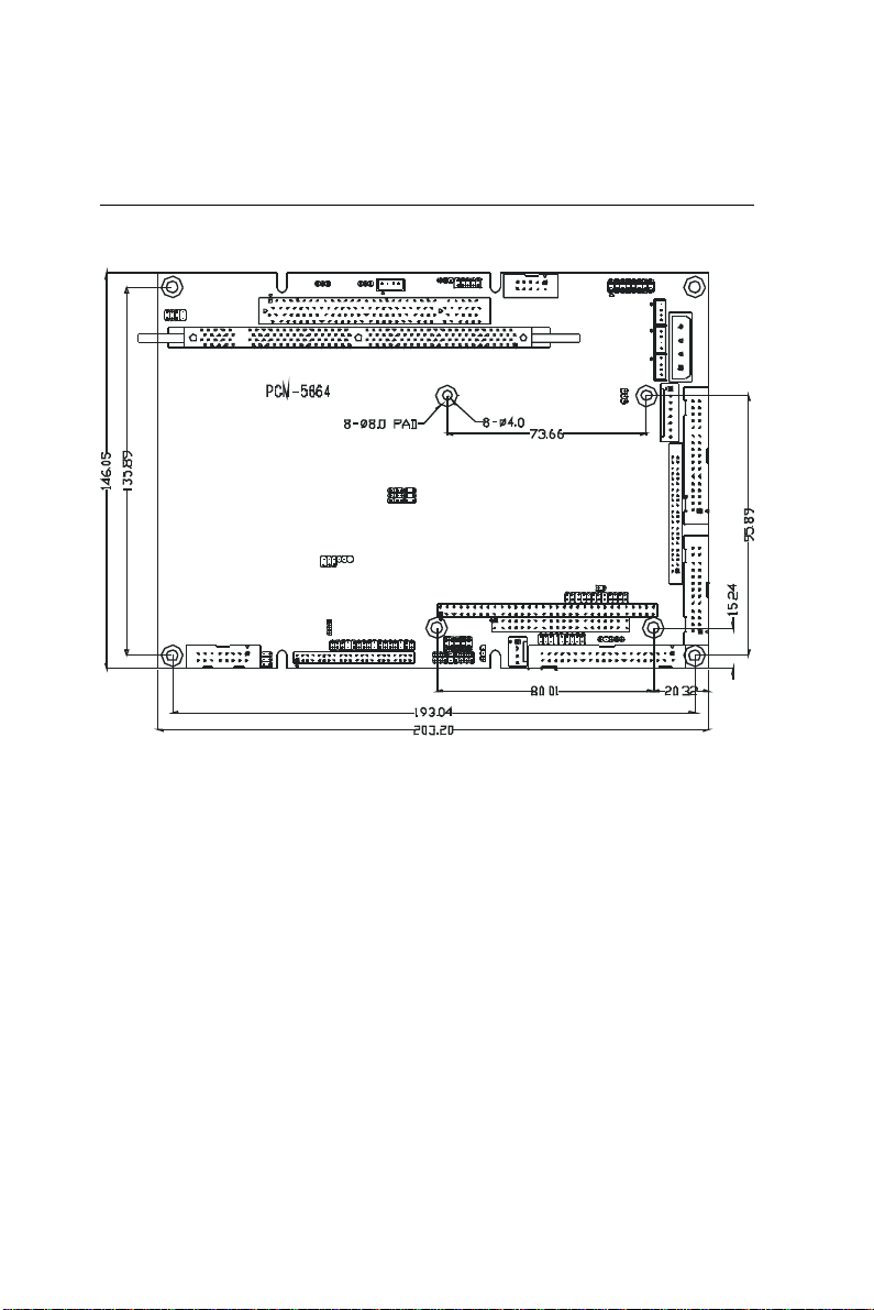
1.4 Board layout and dimensions
Figure 1-1: PCM-5864/L dimensions
Chapter 1 General Information 7
Page 19

8 PCM-5864/L User's Manual
Page 20

CHAPTER
2
Installation
This chapter tells how to set up the
PCM-5864/L hardware. It includes
instructions on setting jumpers, and
connecting peripherals, switches and
indicators. Be sure to read all the safety
precautions before you begin the
installation procedure.
Page 21

2.1 Jumpers
The PCM-5864/L has a number of jumpers that allow you to
configure your system to suit your application. The table below
lists the function of each of the board’s jumpers.
Table 2-1: Jumpers
Label Function
J3 CPU voltage setting
J5 CPU frequency ratio setting
J6 Reserved
J7 Clear CMOS
J8 Backlight signal select
J9 System/PCI clock setting
J10 PCI clock setting
J11 COM4 RI pin setting
J12 COM3 RI pin setting
J13 CompactFlash enable/disable
J14 COM1 RI pin setting
J15 COM2 RI pin setting
J16 LCD power select
J17 Reserved
J18 Buzzer enable setting
J19 COM2 RS-232/422/485 setting
J20 COM2 RS-232/422/485 setting
J21 COM2 RS-232/422/485 setting
J22 Shift clock setting
J23 Audio power source setting
J25 TV out format
JP1 ATX power switch (soft power connector)
JP2 Watchdog timer action
10 PCM-5864/L User's Manual
Page 22

2.2 Connectors
On-board connectors link the PCM-5864/L to external devices
such as hard disk drives, a keyboard, or floppy drives. The table
below lists the function of each of the board’s connectors.
Table 2-2: Connectors
Label Function
CN1 CPU fan connector
CN2 Motherboard fan connector
CN3 Ethernet connector
CN4 Audio connector
CN5 PCI connector
CN6 CD audio input connector
CN7 AUX Line-in connector
CN8 Main power connector
CN9 Keyboard & PS/2 mouse connector
CN10 Floppy drive connector
CN11 PC/104 ISA-bus expansion
CN12 IDE hard drive connector
CN13 Reserved connector
CN14 Parallel port connector
CN15 Front panel connector
CN16 USB connector (channel 1 & 2)
CN17 IR connector
CN18 CRT display connector
CN19 Video-out connector
CN20 Flat panel connector
CN21 Ext. flat panel connector
CN22 Peripheral power connector
CN23 COM port connector
CN30 Video-in (capture)
CN501 CompactFlash connector
CN502 Speaker-out connector (for video playback)
DIM1 DIMM socket
J1 ATX power feature connector
JP3 LVDS connector
Chapter 2 Installation 11
Page 23
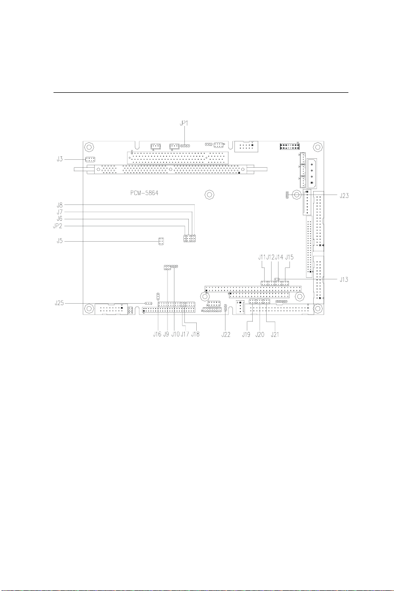
2.3 Locating jumpers
Figure 2-1: Locating jumpers
12 PCM-5864/L User's Manual
Page 24
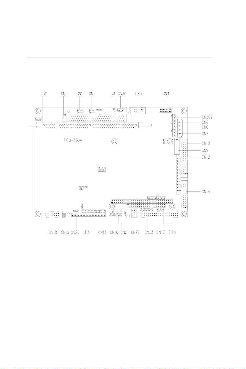
2.4 Locating connectors
2.4.1 Component side
Figure 2-2: Locating connectors (component side)
Chapter 2 Installation 13
Page 25
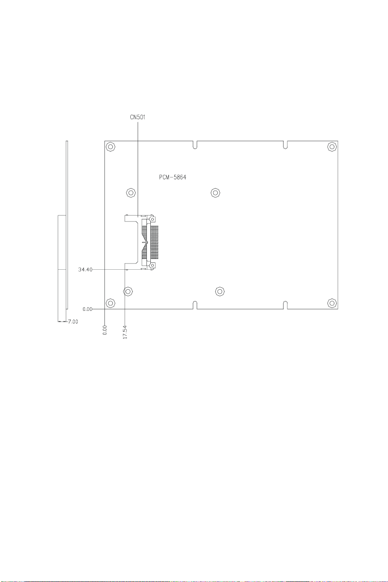
2.4.2 Solder side
Figure 2-3: Locating connectors (solder side)
14 PCM-5864/L User's Manual
Page 26
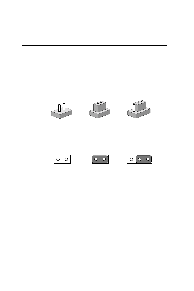
2.5 Setting jumpers
You configure your card to match the needs of your application by
setting jumpers. A jumper is the simplest kind of electric switch. It
consists of two metal pins and a small metal clip (often protected
by a plastic cover) that slides over the pins to connect them. To
“close” a jumper, connect the pins with the clip. To “open” a
jumper, remove the clip. Sometimes a jumper will have three pins,
labeled 1, 2, and 3. In this case, you would connect either pins 1
and 2 or 2 and 3.
1
3
2
Open
Closed Closed 2-3
The jumper settings are schematically depicted in this manual as
follows:
1
Open Closed Closed 2-3
A pair of needle-nose pliers may be helpful when working with
jumpers.
If you have any doubts about the best hardware configuration for
your application, contact your local distributor or sales
representative before you make any changes.
Generally, you simply need a standard cable to make most
connections.
Chapter 2 Installation 15
Page 27
2.6 CPU installation and upgrading
You can upgrade to a higher power Pentium® processor at any
time. Simply remove the old CPU, install the new one, and set the
jumpers for the new CPU type and speed.
Warning! Always disconnect the power cord from y our
chassis when you are working on it. Do not make
connections while the power is on, as sensitive
electronic components can be damaged by the
sudden rush of power . Only e xperienced
electronics personnel should open the PC chassis.
Caution! Always ground yourself to remo ve an y static
charge before touching the PC board. Modern
electronic devices are v ery sensitive to static
electric charges. Use a grounding wrist strap at
all times. Place all electronic components on a
static-dissipative surf ace or in a static-shielded
bag when they are not in the chassis.
2.6.1 Installing a CPU in the PGA type socket
1. If you are upgrading the CPU, remove the old CPU from the
socket. If it is difficult to remove, you may find chip lubricant
(designed for pin-grid-array devices, PGAs) and a chip puller
helpful. Both are available at electronics hobby supply stores.
2. Plug the new CPU into the empty socket. Follow the
instructions that came with the CPU or math coprocessor. If
you have no instructions, do the following: Lubricate the CPU
pins with lubricant made for PGA devices. This will make the
new CPU slide in much more easily, and reduce the chance of
damaging it. Next, carefully align the CPU so that it is parallel
to the socket and the notch on the corner of the CPU
corresponds with the notch on the inside of the socket. Gently
slide the CPU in. There will probably be a gap between the
CPU and the connector when it is fully seated - do not push too
hard!
16 PCM-5864/L User's Manual
Page 28
When you install a new CPU, be sure to adjust the board settings,
such as CPU type and CPU clock. Improper settings may
damage the CPU.
2.6.2 System clock setting (J5, J9, and J10)
J5, J9 and J10 are used to set the CPU and PCI bus speed to
optimize the system performance. The system chipset will sense
the J10 setting to get the bus frequency, then adjust its internal
timing. J9 is used to set the CPU and PCI clock. J5 is the CPU
clock ratio setting jumper. Refer to the CPU Speed Reference
Table (below) for instructions on adjusting the internal clocks
according to the base CPU speed.
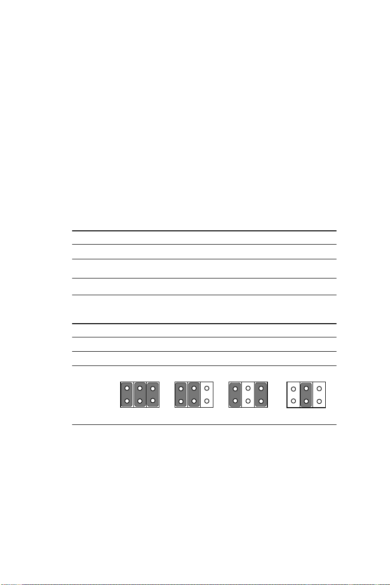
Table 2-3: CPU speed references
CPU Speed (MHz) 75 100 *133 150 166 200 233 266 300 333
Clock setting 50 6 6 66 6 0 66 66 66 66 66 66
Frequency ratio 1.5 1.5 2 2.5 2.5 3 3.5 4 4.5 5
* default setting
Table 2-4: System/PCI clock setting (J9)
System 50 MHz 60 MHZ *66 MHz 75 MHz
PCI 25 MHz 30 MHz *33.3 MHz 37.5 MHz
2 4 62 4 62 4 6
2 4 6
* default setting
1 3 51 3 51 3 5
Chapter 2 Installation 17
1 3 5
Page 29
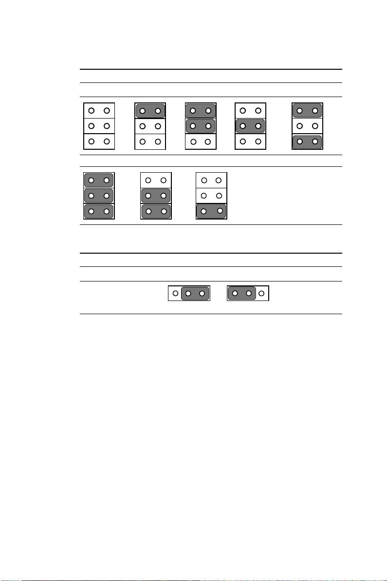
Table 2-5: CPU frequency ratio (J5)
1.5 /3.5 2* 2.5 3 4
1
3
5
2
4
6
4.5 5 5.5 (reserved)
1
3
5
2
4
6
1
3
5
* default setting
Table 2-6: PCI/clock setting (J10)
*33 MHz CPU CLK/2
J10
1 2 3 1 2 3
* default setting
1
3
5
2
4
6
2
4
6
18 PCM-5864/L User's Manual
Page 30

2.6.3 CPU voltage setting (J3)
JP1 must be set to match the CPU type. The chart below shows the
proper jumper settings for their respective Vcc (core). (The Vcc (I/
O) for CPU is fixed to be 3.3V)
Table 2-7: CPU voltage setting (J3)
VCC (CORE) 1-2 3-4 5-6 7-8
NONE open open open open
2.10 V closed open open open
2.20 V open closed open open
2.30 V closed closed open open
2.40 V open open closed open
2.50 V closed open closed open
2.60 V open closed closed open
2.70 V closed closed closed open
2.80 V open open open closed
2.90 V closed open open closed
3.00 V open closed open closed
3.10 V closed closed open closed
3.20 V open open closed closed
3.30 V* closed open closed closed
3.40 V open closed closed closed
3.50 V closed closed closed closed
* default setting
Chapter 2 Installation 19
Page 31
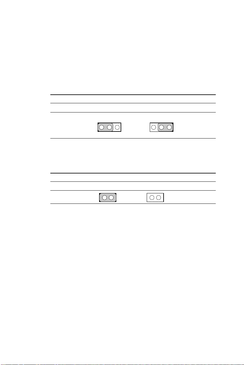
2.6.4 CMOS clear (J7)
Warning: T o a v oid damaging the computer , alw ays turn off
the power supply before setting “Clear CMOS .”
Before turning on the power supply, set the
jumper back to “3.0 V Battery On. ”
Table 2-8: CMOS clear (J7)
*3.0 V Battery on Clear CMOS
1 2 3 1 2 3
J7
* default setting
2.6.5 Buzzer enable/disable (J18)
Table 2-9: Buzzer enable/disable (J18)
*Enabled Disabled
J18
* default setting
20 PCM-5864/L User's Manual
Page 32

2.7 Installing system memory (DIMMs)
You are able to install memory ranging from 8 to 128 MB of
DIMM onto your PCM-5864/5L card. The card provides one
168-pin DIMM socket, which accepts 8, 16, 32, 64 or 128 MB
3.3 V power level EDO/synchronous DIMMs.
2.7.1 Installing DIMMs
The procedure for installing DIMMs is described below. Please
follow these steps carefully. The number of pins are different on
either side of the breaks, so the module can only fit in one way.
DIMM modiles have different pin contacts on each side, and
therefore have a higher pin density.
1. Make sure that the two handles of the DIMM socket are in the
“open” position. i.e. The handles remain leaning outward.
2. Slowly slide the DIMM module along the plastic guides on
both ends of the socket.
3. Press the DIMM module right down into the socket, until you
hear a click. This is when the two handles have automatically
locked the memory module into the correct position of the
socket.
To remove the memory module, just push both handles outward,
and the module will be ejected from the socket.
2.8 IDE hard drive connector (CN12)
You can attach one or two Enhanced Integrated Device
Electronics hard disk drives to the PCM-5864/L’s internal
controller. The PCM-5864/L’s IDE controller uses a PCI local-bus
interface. This advanced IDE controller supports faster data
transfer, PID mode 3, and mode 4.
Chapter 2 Installation 21
Page 33

2.8.1 Connecting the hard drive
Connecting drives is done in a daisy-chain fashion. It requires one
of two cables (not included in this package), depending on the
drive size. 1.8" and 2.5" drives need a 1 x 44-pin to 2 x 44-pin flatcable connector. 3.5" drives use a 1 x 44-pin to 2 x 40-pin
connector.
Wire number 1 on the cable is red or blue, and the other wires are
gray.
1. Connect one end of the cable to CN12. Make sure that the red
(or blue) wire corresponds to pin 1 on the connector, which is
labeled on the board (on the right side).
2. Plug the other end of the cable into the Enhanced IDE hard
drive, with pin 1 on the cable corresponding to pin 1 on the
hard drive. (See your hard drive’s documentation for the
location of the connector.)
Connect a second drive as described above.
Unlike floppy drives, IDE hard drives can connect to either end of
the cable. If you install two drives, you will need to set one as the
master and one as the slave by using jumpers on the drives. If you
install just one drive, set it as the master.
2.8.2 CompactFlash (CN501)
The CompactFlash card shares an IDE channel which can be
enabled/disabled via J13.
Table 2-10: CompactFlash enable/disable (J13)
Enabled Disabled
J13
22 PCM-5864/L User's Manual
Page 34

2.9 Floppy drive connector (CN10)
You can attach up to two floppy drives to the PCM-5864/5L’s
on-board controller. You can use any combination of 5.25” (360
KB and 1.2 MB) and/or 3.5” (720 KB, 1.44 MB, and 2.88 MB)
drives.
A 34-pin daisy-chain drive connector cable is required for a
dual-drive system. On one end of the cable is a 34-pin flat-cable
connector. On the other end are two sets of floppy disk drive
connectors. Each set consists of a 34-pin flat-cable connector
(usually used for 3.5” drives) and a printed-circuit board
connector (usually used for 5.25” drives).
2.9.1 Connecting the floppy drive
1. Plug the 34-pin flat-cable connector into CN10. Make sure that
the red wire corresponds to pin one on the connector.
2. Attach the appropriate connector on the other end of the cable
to the floppy drive(s). You can use only one connector in the
set. The set on the end (after the twist in the cable) connects to
the A: drive. The set in the middle connects to the B: drive.
3. If you are connecting a 5.25” floppy drive, line up the slot in
the printed circuit board with the blocked-off part of the cable
connector.
If you are connecting a 3.5” floppy drive, you may have
trouble determining which pin is number one. Look for a
number printed on the circuit board indicating pin number one.
In addition, the connector on the floppy drive may have a slot.
When the slot is up, pin number one should be on the right.
Check the documentation that came with the drive for more
information.
If you desire, connect the B: drive to the connectors in the
middle of the cable as described above.
In case you need to make your own cable, you can find the pin
assignments for the board’s connector in Appendix C.
Chapter 2 Installation 23
Page 35

2.10 Parallel port connector (CN14)
Normally, the parallel port is used to connect the card to a printer.
The PCM-5864/L includes a multi-mode (ECP/EPP/SPP) parallel
port accessed via CN14, a 26-pin flat-cable connector. You will
need an adapter cable if you use a traditional DB-25 connector.
The adapter cable has a 26-pin connector on one end, and a DB-25
connector on the other.
The parallel port is designated as LPT1, and can be disabled or
changed to LPT2 or LPT3 in the system BIOS setup.
The parallel port interrupt channel is designated to be IRQ7.
You can select ECP/EPP DMA channel via BIOS setup.
2.11 Keyboard and PS/2 mouse connector (CN9)
The PCM-5864/L board provides a keyboard connector that
supports both a keyboard and a PS/2 style mouse. In most cases,
especially in embedded applications, a keyboard is not used. If the
keyboard is not present, the standard PC/AT BIOS will report an
error or fail during power-on self-test (POST) after a reset. The
PCM-5864/L’s BIOS standard setup menu allows you to select
“All, But Keyboard” under the “Halt On” selection. This allows
no-keyboard operation in embedded system applications, without
the system halting under POST.
24 PCM-5864/L User's Manual
Page 36

2.12 Front panel connector (CN15)
Next, you may want to install external switches to monitor and
control the PCM-5864/L. These features are optional: install them
only if you need them. The front panel connector (CN15) is an
8-pin male, dual in-line header. It provides connections for a
speaker, hard disk access indicator, watchdog output, and an input
switch for resetting the card.
2.12.1 Speaker
The PCM-5864/L can drive an 8 W speaker at 0.5 watts. Make
sure that alternatives to this specification do not overload the card.
2.12.2 LED interface
The front panel LED indicator for hard disk access is an active low
signal (24 mA sink rate).
2.12.3 Watchdog output
When the PCM-5864/L’s watchdog timer times out, the front
panel pin 6 will output an active low pulse signal (25mA sink rate
for 1 second).
2.12.4 Reset switch
If you install a reset switch, it should be an open single pole
switch. Momentarily pressing the switch will activate a reset. The
switch should be rated for 10 mA, 5 V.
If you need to make your own cable, you can find the pin
assignments for the board’s connector in Appendix C.
Chapter 2 Installation 25
Page 37

2.13 Power connectors (CN1, CN2, CN8, CN22)
2.13.1 Peripheral power connector, -5 V, -12 V (CN22)
Supplies secondary power to devices that require -5 V and -12 V.
2.13.2 Main power connector, +5 V, +12 V (CN8)
Supplies main power to the PCM-5864/L (+5 V), and to devices
that require +12 V.
2.13.3 CPU Fan power supply connector (CN1)
Provides power supply to CPU cooling fan. Only present when +5
V and +12 V power is supplied to the board.
2.13.4 Motherboard fan power supply connector (CN2)
This connector (CN2) is reserved for the integrated system cooling
fan.
26 PCM-5864/L User's Manual
Page 38
2.14 ATX power control connector (JP1, J1)
2.14.1 ATX feature connector (J1) and soft power switch connector (JP1)
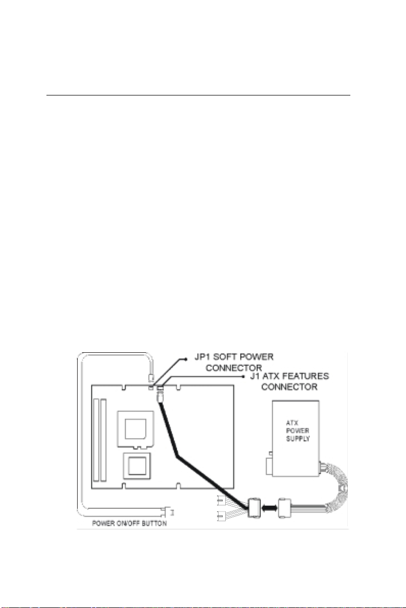
The PCM-5864/L can support an advanced soft power switch
function, if an ATX power supply is used. To enable the soft
power switch function:
1. Get the specially designed ATX-to-PS/2 power cable
(PCM-5864/L optional item, part nos. 1700000450 and
1700000452).
2. Connect the 3-pin plug of the cable to J1 (ATX feature
connector).
3. Connect the power on/off button to JP1. (A momentary type of
button should be used.)
Important: Make sure that the ATX power supply can take at
least a 10 mA load on the 5 V standb y lead
(5VSB). If not, you ma y ha v e difficulty powering
on your system.
Figure 2-4: Wiring for ATX soft power switch function
Chapter 2 Installation 27
Page 39

2.15 IR connector (CN17)
This connector supports the optional wireless infrared transmitting
and receiving module. This module mounts on the system case.
You must configure the setting through BIOS setup.
2.16 Audio interfaces (CN4, CN6, CN7, CN502) (PCM-5864 only)
The PCM-5864 is equipped with a high-quality audio interface,
which provides 16-bit CD-quality recording and playback as well
as OPL3 compatible FM music. It is supported by all major
operating systems, and is 100% Sound Blaster Pro compatible.
2.16.1 Audio connector (CN4)
The PCM-5864 provides all major audio signals on a 16-pin
flat-cable connector, CN4. These audio signals include
Microphone in (mono), Line in (stereo), Line out (stereo), and
Speaker out (stereo). If you use traditional telephone jack
connectors for these audio signals, you will need an adapter cable.
2.16.2 CD audio input connector (CN6)
Any CD-ROM drive can provide analog audio signal output when
used as a music CD player. The CN6 on PCM-5864 is a connector
to input CD audio signals into the audio controller. The audio
cable of your CD-ROM drive will be used to connect to CN6.
2.16.3 Aux line-in connector (CN7)
The CN7 Line in signal is the same as CN4. It is reserved for the
AV connector via a customized cable.
2.16.4 Speaker-out connector (CN502)
The CN502 Speaker out signal is the same as the CN4. It is
reserved for the AV connector via a customized cable.
28 PCM-5864/L User's Manual
Page 40
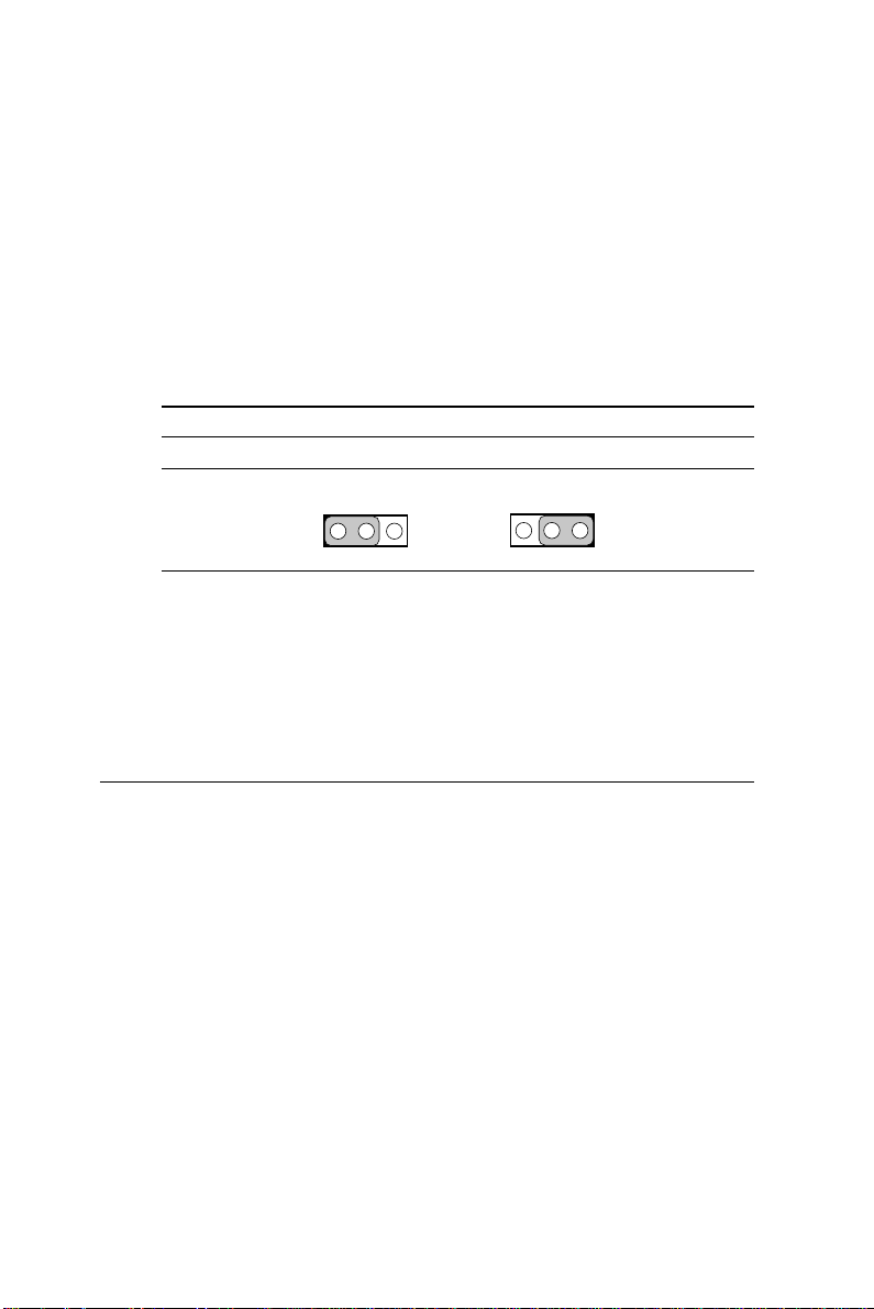
2.16.5 Audio power source setting (J23)
The PCM-5864 is designed to work with a single +5 V power
supply. The audio interface can also function normally under
single +5V power supply, but most audio controllers require an
independent power source generated from a +12 V power supply.
The independent power source avoids the noise from the other
digital circuits. The PCM-5864‘s audio interface can accept +12 V
power to provide improved quality audio. This is done via J23.
Table 2-11: Audio power source setting
*+5 V +12 V
J23
1 2 3 1 2 3
* default setting
Configuration of the audio interface is done entirely via the
software utility. You do not have to set any jumpers. Refer to
Chapter 6 for audio setup details.
2.17 COM port connector (CN23)
The PCM-5864/L provides four serial ports (COM1, 3, 4: RS-232;
COM2: RS-232/422/485) in one COM port connector. The COM
port connector is a 40-pin, dual-inline, male header. It provides
connections for serial devices (a mouse, etc.) or a communication
network. You can find the pin assignments for the COM port
connector in Appendix C.
2.17.1 COM2 RS-232/422/485 setting (J19, J20, J21)
COM2 can be configured to operate in RS-232, RS-422, or RS485 mode. This is done via J19 and J20.
Chapter 2 Installation 29
Page 41
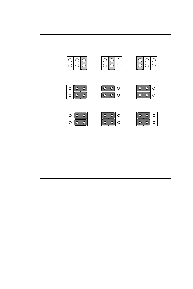
Table 2-12: COM2 RS-232/422/485 settings (J19, J20, J21)
*RS-232 RS-422 RS-485
J19
J20
J21
5
111
44 4
555333111
6446642 2 2
555333111
6446642 2 2
5
5
333
666
222
* default setting
The IRQ and the address range for COM1, 2, 3, 4 are fixed.
However, if you wish to disable the port or change these
parameters later you can do this in the system BIOS setup. The
table below shows the settings for the PCM-5864/5864L’s serial
ports.
Table 2-13: Serial port default settings
Port Address range Interrupt
COM1 3F8 ~ 3FF IRQ4
COM2 2F8 ~ 2FF IRQ3
COM3 3E8 ~ 3EF IRQ10
COM4 2E8 ~ 2EF IRQ5
2.17.2 COM3/COM4 RI pin setting (J11, J12)
COM3 and COM4 can supply +5 V or +12 V power to the serial
devices via the RI pin of the COM port connector. The outputs of
the COM3 and COM4 RI pins are selected by setting J11 and J12
respectively.
30 PCM-5864/L User's Manual
Page 42
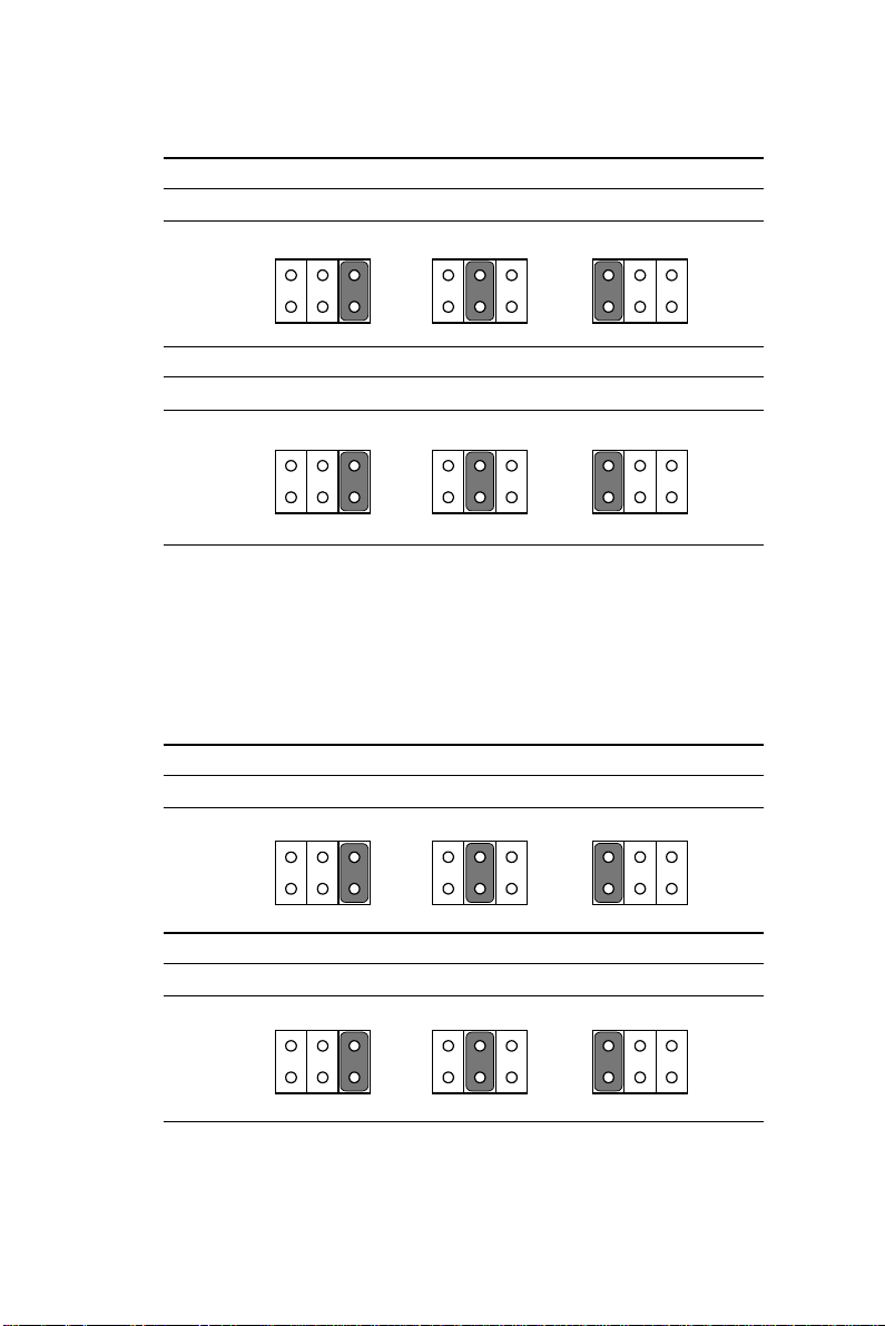
Table 2-14: COM3 RI pin settings (J12)
+5 V +12 V *RI
6
J12
65432
65432
54321
Table 2-15: COM4 RI pin settings (J11)
1
1
+5 V +12 V *RI
65432
1
J11
6
54321
65432
1
2.17.3 COM1/COM2 RI pin setting (J14, J15)
COM1and COM2 can supply +5 V or +12 V power to the serial
devices via the RI pin of the COM port connector. The outputs of
the COM3 and COM4 RI pins are selected by setting J14 and J15
respectively.
Table 2-16: COM1 RI pin settings (J14)
+5 V +12 V *RI
6
J14
54321
Table 2-17: COM2 RI pin settings (J15)
65432
+5 V +12 V *RI
6
65432
1
65432
1
65432
J15
54321
* default setting
1
Chapter 2 Installation 31
1
Page 43

2.18 VGA interface connections
The PCM-5864/L’s PCI SVGA interface can drive conventional
CRT displays and is capable of driving a wide range of flat panel
displays, including electroluminescent (EL), gas plasma, passive
LCD and active LCD displays. The board has two connectors to
support these displays, one for standard CRT VGA monitors and
one for flat panel displays.
2.18.1 CRT display connector (CN18)
CN18 is a 16-pin, dual-inline header used for conventional CRT
displays. A simple one-to-one adapter can be used to match CN18
to a standard 15-pin D-SUB connector commonly used for VGA.
Pin assignments for CRT display connector CN18 are detailed in
Appendix C.
2.18.2 Flat panel display connector (CN20)
CN20 consists of a 44-pin, dual-inline header which can support a
24-bit LCD panel. Power supply (+12 V) present on CN20
depends on the supply connected to the board.
The PCM-5864/L provides a bias control signal on CN20 that can
be used to control the LCD bias voltage. It is recommended that
the LCD bias voltage not be applied to the panel until the logic
supply voltage (+5 V or +3.3 V) and panel video signals are
stable. Under normal operation, the control signal (ENAVEE) is
active high. When the PCM-5864/L’s power is applied, the control
signal is low until just after the relevant flat panel signals are
present.
2.18.3 Extension flat panel connector (CN21)
The PCM-5864/L supports a 36-bit LCD panel which must be
connected to both the CN20 (44-pin) and the CN21 (16-pin). The
pin assignments for both CN20 and the CN21 can be found in
Appendix C.
32 PCM-5864/L User's Manual
Page 44
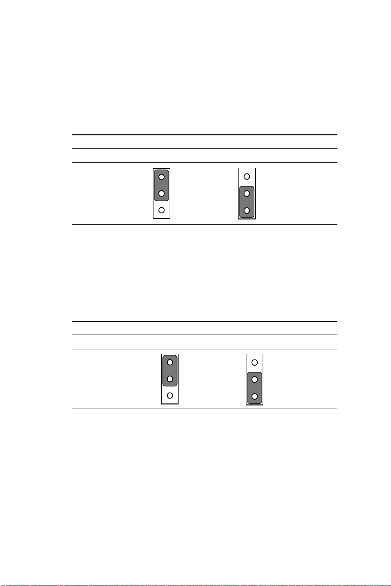
2.18.4 LCD power setting (J16)
The PCM-5864/L’s PCI SVGA interface supports 5 V and 3.3 V
LCD displays. By changing the setting of J16, you can select the
panel video signal level to be 5 V or 3.3 V.
Table 2-18: LCD power setting
*5 V 3.3 V
J16
1
2
3
1
2
3
* default setting
2.16.5 LCD shift clock setting (J22)
The customer can use a shift clock (SHFCLK) or an asyn. shift
clock (ASHFCLK) by using the J22 setting for a different LCD
panel application.
Table 2-19: LCD shift clock setting
SHFCLK* ASHFCLK
J22
* default setting
1
2
3
1
2
3
Chapter 2 Installation 33
Page 45
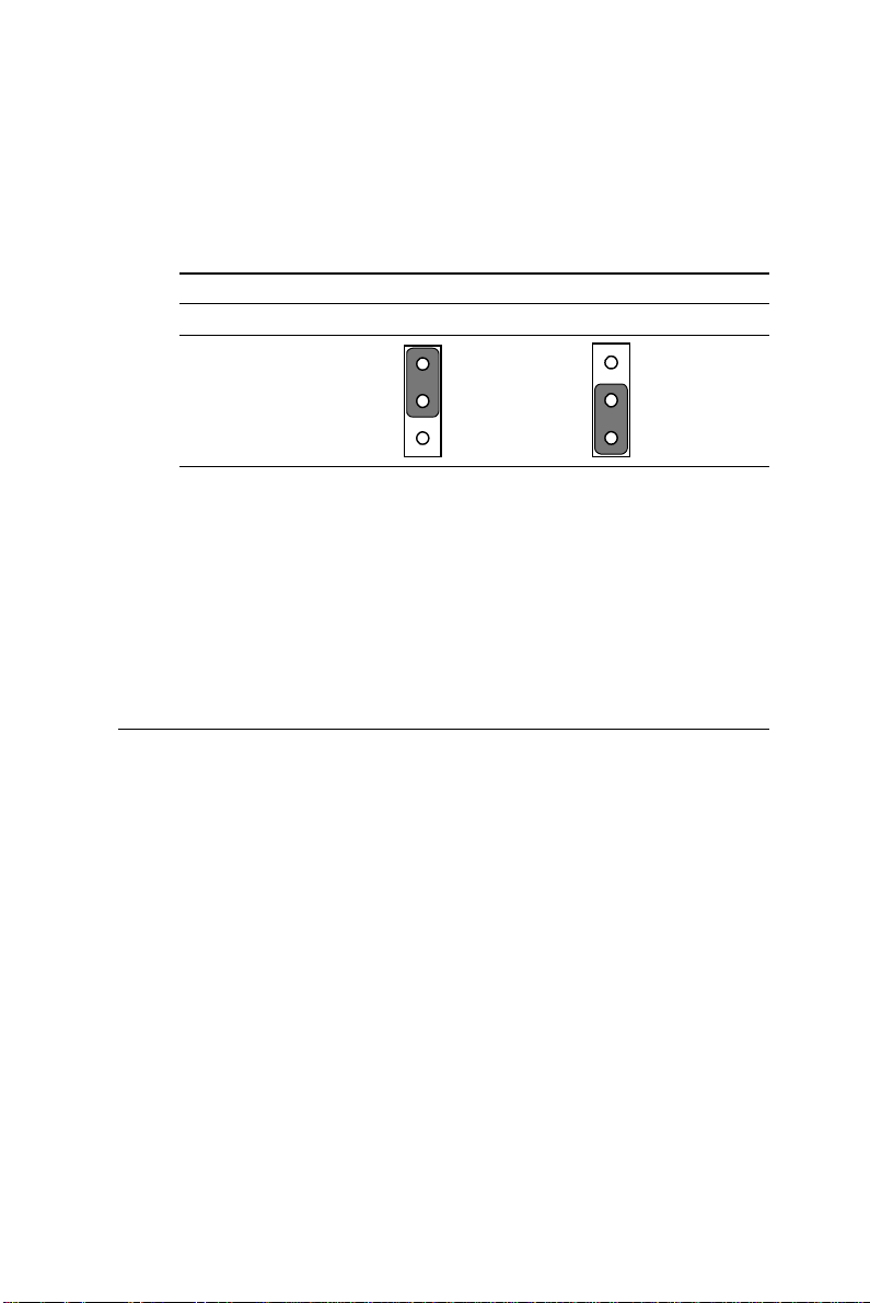
2.18.6 LCD backlight signal setting (J8)
The backlight signal can either choose positive enable or negative
enable when using the J8 setting.
Table 2-20: LCD backlight signal setting (J8)
Positive signal Negative signal
1
J8
2
1
2
3
Configuration of the VGA interface is done completely via the
software utility. You do not have to set any jumpers. Refer to
Chapter 3 for software setup details.
Refer to Chapter 3 for details on connecting the five standard
LCDs: Sharp LM64183P, LM64P89, Toshiba LTM10C042, Sharp
64C142, and Planar EL display.
2.19 Ethernet configuration
The PCM-5864/L is equipped with a high performance 32-bit
PCI-bus Ethernet interface which is fully compliant with IEEE
802.3U 10/100Mbps CSMA/CD standards. It is supported by all
major network operating systems.
The medium type can be configured via the RSET8139.EXE
program included on the utility disk. (See Chapter 3 for detailed
information.)
2.19.1 100Base-T connector (CN3)
100Base-T connects to the PCM-5864/L via an adapter cable to a
10-pin polarized header (CN3). For 10Base-T RJ-45 operation, an
adapter cable converting CN3 into a standard RJ-45 jack is
required.
3
34 PCM-5864/L User's Manual
Page 46
2.19.2 Network boot
The Network Boot feature can be utilized by incorporating the
Boot ROM image files for the appropriate network operating
system. The Boot ROM BIOS files are included in the system
BIOS, which is on the utility CD disc.
2.20 Watchdog timer configuration
An on-board watchdog timer reduces the chance of disruptions
which EMP (electro-magnetic pulse) interference can cause. This
is an invaluable protective device for standalone or unmanned
applications. Setup involves one jumper and running the control
software (refer to Appendix A).
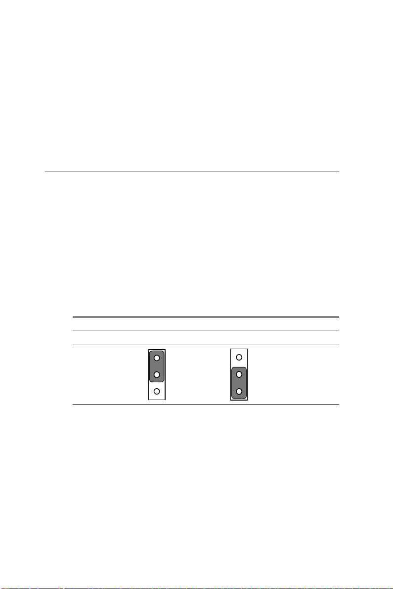
2.20.1 Watchdog timer action (JP2)
When the watchdog timer activates (CPU processing has come to
a halt), it can reset the system or generate an interrupt on IRQ11.
This can be set via setting JP2 as shown below:
Table 2-21: Watchdog timer action (JP2)
*System reset IRQ11
1
2
JP2
1
2
* default setting
3
3
Chapter 2 Installation 35
Page 47

2.21 USB connectors (CN16)
The PCM-5864/L board provides two USB (Universal Serial Bus)
ports which gives complete plug and play, and hot attach/detach
for up to 127 external devices. The USB interfaces comply with
USB specification Rev. 1.0, and are fuse protected.
The USB interface is accessed through one 5-pin flat-cable
connector, CN16. You will need an adapter cable if you use a
standard USB connector. The adapter cable has a 5-pin connector
on one end and an USB connector on the other.
The USB interfaces can be disabled in the system BIOS setup.
36 PCM-5864/L User's Manual
Page 48
2.22 Video interfaces (CN19, CN30) (PCM-5864 only)
The PCM-5864 board provides Video-in (CN19) and Video-out
(TV-out) (CN30). They consist of a 6-pin and an 8-pin dual-inline
header respectively. Video capture supports RCA and S-video
connectors via an optional cable kit. Its Video-in and Video-out
generators use both NTSC and PAL format.
To set up your video interface:
1. Set J25 according to whether you want NTSC or PAL format.
See Table 2-22 below.
2. Run the appropriate installation software program, located in
the utility disk.
For NTSC format, the file is 55xntsc.exe, located in:
Biscuit\5864\Video.100\69000\TV-out\
For PAL format, the file is 55xpal.exe, located in:
Biscuit\5864\Video.100\69000\TV-out\
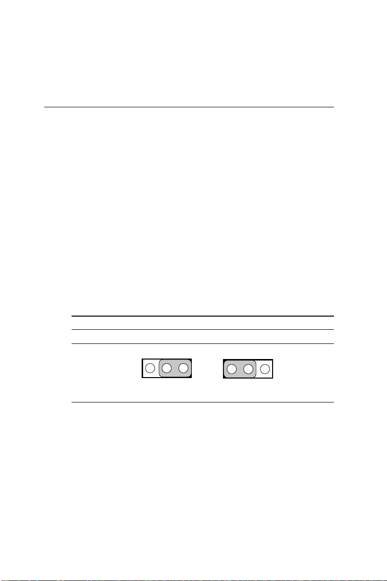
Table 2-22: TV-out format select (J25)
NTSC* PAL
J25
1223
1
3
Chapter 2 Installation 37
Page 49

38 PCM-5864/L User's Manual
Page 50

CHAPTER
3
Software
Configuration
This chapter details the software
configuration information. It shows
you how to configure the card to match
your application requirements. AWARD
System BIOS is covered in Chapter 4.
Sections include:
• Introduction
• Connections for four standard LCDs
• Ethernet interface configuration
Page 51

3.1 Introduction
The PCM-5864/L system BIOS and custom drivers are located in
a 256 Kbyte, 32-pin (JEDEC spec.) Flash ROM device, designated
U18. A single Flash chip holds the system BIOS, VGA BIOS and
network Boot ROM image. The display can be configured via
CMOS settings. This method minimizes the number of chips and
difficulty of configuration. To set different types of LCD panels,
please choose “panel type” from the “integrated peripherals”
menu in CMOS setup.
3.2 Connections for five standard LCDs
3.2.1 Connections to Sharp LM64183P, LM64P89 (640 x 480 DSTN MONO LCD)
Table 3-1: Connections to Sharp LM64183P & LM64P89
LM64183/64P89 PCM-5864/L CN15
Pin Name Pin Name
CN1-1 S 36 FLM
CN1-2 CP1 38 LP
CN1-3 CP2 35 SHFCLK
CN1-4 DISP 5 +5 V
CN1-5 VDD 6 +5 V
CN1-6 VSS 3 GND
CN1-7 VEE - External power*
CN1-8 DU0 12 P3
CN1-9 DU1 11 P2
CN1-10 DU2 10 P1
CN1-11 DU3 9 P0
CN1-12 DL0 16 P7
CN1-13 DL1 15 P6
CN1-14 DL2 14 P5
CN1-15 DL3 13 P4
* LM64183P -17 V LM64P89 -20 V
Note: Standard BIOS supports TFT and DSTN LCD
panels.
40 PCM-5864/L User's Manual
Page 52

3.2.2 Connections to PLANAR EL (640 x 480 AD4 EL)
Table 3-2: Connections to PLANAR EL
PLANAR 640 x 480 AD4 PCM-5864/L CN15
Pin Name Pin Name
1 GND 3 GND
2 DO 21 P12
3 GND 3 GND
4 D1 22 P13
5 GND 3 GND
6 D2 23 P14
7NC ——
8 D3 24 P15
9NC ——
10 D4 17 P8
11 NC — —
12 D5 18 P9
13 NC — —
14 D6 19 P10
15 GND 4 GND
16 D7 20 P11
17 GND 4 GND
18 VCLK 42 ASHFCLK
19 GND 4 GND
20 /BLANK — —
21 GND 8 GND
22 HS 37 M
23 NC — —
24 VS 36 FLM
25 NC — —
26 SELFTST 39 GND
27 COLMAP 39 GND
28 ENABLE — —
29 RESERVED — —
30 /LOWPOW — —
31,32 NC — —
33 RESERVED — —
34 NC ——
Chapter 3 Software Configuration 41
Page 53

3.2.3 Connections to Toshiba LTM10C042 (640 x 480 TFT color LCD)
Table 3-3: Connections to Toshiba LTM10DC042
LTM10C042 PCM-5864/L CN15
Pin Name Pin Name
1 GND 3 GND
2 CLK 35 SHFCLK
3 GND 4 GND
4 R0 27 P18
5 R1 28 P19
6 R2 29 P20
7 GND 8 GND
8 R3 30 P21
9 R4 31 P22
10 R5 32 P23
11 GND 33 GND
12 G0 19 P10
13 G1 20 P11
14 G2 21 P12
15 GND 33 GND
16 G3 22 P13
17 G4 23 P14
18 G5 24 P15
19 GND 34 GND
20 ENAB 37 M
21 GND 34 GND
22 B0 11 P2
23 B1 12 P3
24 B2 13 P4
25 GND 39 GND
26 B3 14 P5
27 B4 15 P6
28 B5 16 P7
29 GND 39 GND
30 VDD 5 +5 V
31,32 VDD 6 +5 V
42 PCM-5864/L User's Manual
Page 54

3.2.4 Connections to Sharp LM64C142 (640 x 480 DSTN color LCD)
Table 3-4: Connections to Sharp LM64C142
LM64C142 PCM-5864/L CN15
Pin Name Pin Name
CN1-1 YD 36 FLM
CN1-2 LP 38 LP
CN1-3 XCX 35 SHFCLK
CN1-4 DISP 5 +5 V
CN1-5 VDD 6 +5 V
CN1-6 VSS 3 GND
CN1-7 VEE — +27*
CN1-8 DU0 20 P11
CN1-9 DU1 19 P10
CN1-10 DU2 18 P9
CN1-11 DU3 17 P8
CN1-12 DU4 12 P3
CN1-13 DU5 11 P2
CN1-14 DU6 10 P1
CN1-15 DU7 9 P0
CN2-1 VSS 4 GND
CN2-2 DL0 24 P15
CN2-3 DL1 23 P14
CN2-4 DL2 22 P13
CN2-5 DL3 21 P12
CN2-6 DL4 16 P7
CN2-7 DL5 15 P6
CN2-8 DL6 14 P5
CN2-9 DL7 13 P4
CN2-10 VSS 8 GND
Chapter 3 Software Configuration 43
Page 55

3.2.5 Connections to Toshiba LTM12C275A
(800 x 600 TFT color LCD)
Table 3-5: Connections to Toshiba LTM12C2775A
LTM12C275A PCM-5864/L CN15
Pin Name Pin Name
1 GND 3 GND
2 NCLK 35 SHFCLK
3NC -NC
4NC -NC
5 GND 4 GND
6 R0 27 P18
7 R1 28 P19
8 R2 29 P20
9 R3 30 P21
10 R4 31 P22
11 R5 32 P23
12 GND 8 GND
13 G0 19 P10
14 G1 20 P11
15 G2 21 P12
16 G3 22 P13
17 G4 23 P14
18 G5 24 P15
19 GND 33 GND
20 B0 11 P2
21 B1 12 P3
22 B2 13 P4
23 B3 14 P5
24 B4 15 P6
25 B5 16 P7
26 ENAB 37 M/DE
27 GND 34 GND
28 VCC 5 +5 V
29 VCC 6 +5 V
30 GND 39 GND
44 PCM-5864/L User's Manual
Page 56

3.3 Ethernet software configuration
The PCM-5864/L’s on-board Ethernet interface supports all major
network operating systems. To configure the medium type, to view
the current configuration, or to run diagnostics, do the following:
1. Power the PCM-5864/L on. Make sure that the RSET8139.EXE
file is located in the working drive.
2. At the prompt, type RSET8139.EXE and press <Enter>. The
Ethernet configuration program will then be displayed.
3. This simple screen shows all the available options for the
Ethernet interface. Just highlight the option you wish to change
by using the Up and Down keys. To change a selected item,
press <Enter>, and a screen will appear with the available
options. Highlight your option and press <Enter>. Each
highlighted option has a helpful message guide displayed at the
bottom of the screen for additional information.
4. After you have made your selections and are sure this is the
configuration you want, press ESC. A prompt will appear
asking if you want to save the configuration. Press Y if you
want to save.
The Ethernet Setup Menu also offers three very useful diagnostic
functions. These are:
1. Run EEPROM Test
2. Run Diagnostics on Board
3. Run Diagnostics on Network
Each option has its own display screen that shows the format and
result of any diagnostic tests undertaken.
Note: For Ethernet installation, please see Chapter 8.
Chapter 3 Software Configuration 45
Page 57

46 PCM-5864/L User's Manual
Page 58

CHAPTER
4
Award BIOS Setup
This chapter describes how to set BIOS
configuration data.
Page 59

4.1 System test and initialization
These routines test and initialize board hardware. If the routines
encounter an error during the tests, you will either hear a few short
beeps or see an error message on the screen. There are two kinds
of errors: fatal and non-fatal. With non-fatal errors, the system can
usually continue the boot sequence . Non-fatal error messages
usually appear on the screen along with the following instructions:
press <F1> to RESUME
Write down the message and press the F1 key to continue the boot
sequence.
4.1.1 System configuration verification
These routines check the current system configuration against the
values stored in the board’s CMOS memory. If they do not match,
the program outputs an error message. You will then need to run
the BIOS setup program to set the configuration information in
memory.
There are three situations in which you will need to change the
CMOS settings:
1. You are starting your system for the first time
2. You have changed the hardware attached to your system
3. The CMOS memory has lost power and the configuration
information has been erased.
The PCM-5864/L’s CMOS memory has an integral lithium battery
backup. The battery backup should last ten years in normal
service. When it finally runs down, you will need to replace the
complete unit.
48 PCM-5864/L User's Manual
Page 60
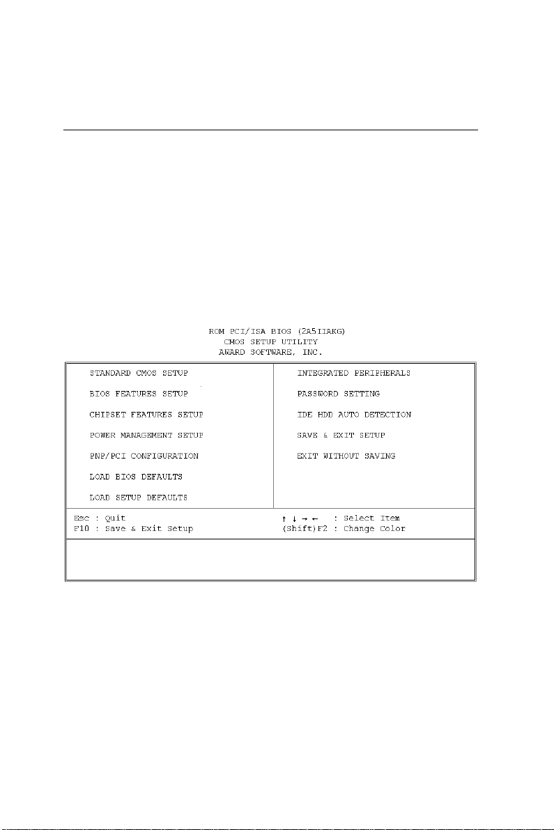
4.2 AWARD BIOS setup
Award’s BIOS ROM has a built-in Setup program that allows
users to modify the basic system configuration. This type of
information is stored in battery-backed CMOS RAM, so that it
retains the Setup information when the power is turned off.
4.2.1 Entering setup
Power on the computer and press <Del> immediately. This will
allow you to enter Setup.
Figure 4-1: Setup program initial screen
Chapter 4 Award Bios Setup 49
Page 61
4.2.2 Standard CMOS setup
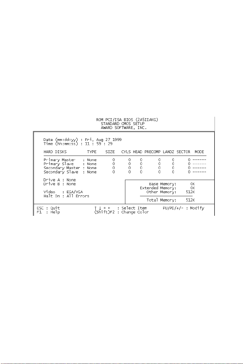
When you choose the STANDARD CMOS SETUP option from
the INITIAL SETUP SCREEN menu, the screen shown below is
displayed. This standard Setup menu allows users to configure
system components such as date, time, hard disk drive, floppy
drive and display. Once a field is highlighted, online help
information is displayed at the bottom left of the Menu screen.
Figure 4-2: CMOS setup screen
50 PCM-5864/L User's Manual
Page 62
4.2.3 BIOS features setup
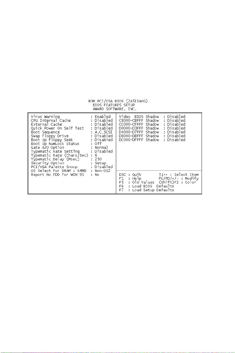
By choosing the BIOS FEATURES SETUP option from the
INITIAL SETUP SCREEN menu, the screen below is displayed.
This sample screen contains the manufacturer’s default values for
the PCM-5864/L.
Figure 4-3: BIOS features setup
Chapter 4 Award Bios Setup 51
Page 63
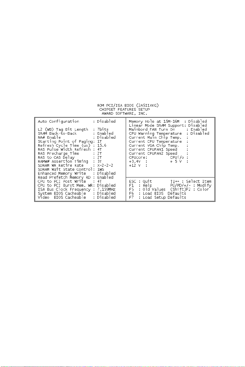
4.2.4 Chipset features setup
By choosing the CHIPSET FEATURES SETUP option from the
INITIAL SETUP SCREEN menu, the screen below is displayed.
This sample screen contains the manufacturer’s default values for
the PCM-5864/L.
Figure 4-4: Chipset features setup
52 PCM-5864/L User's Manual
Page 64
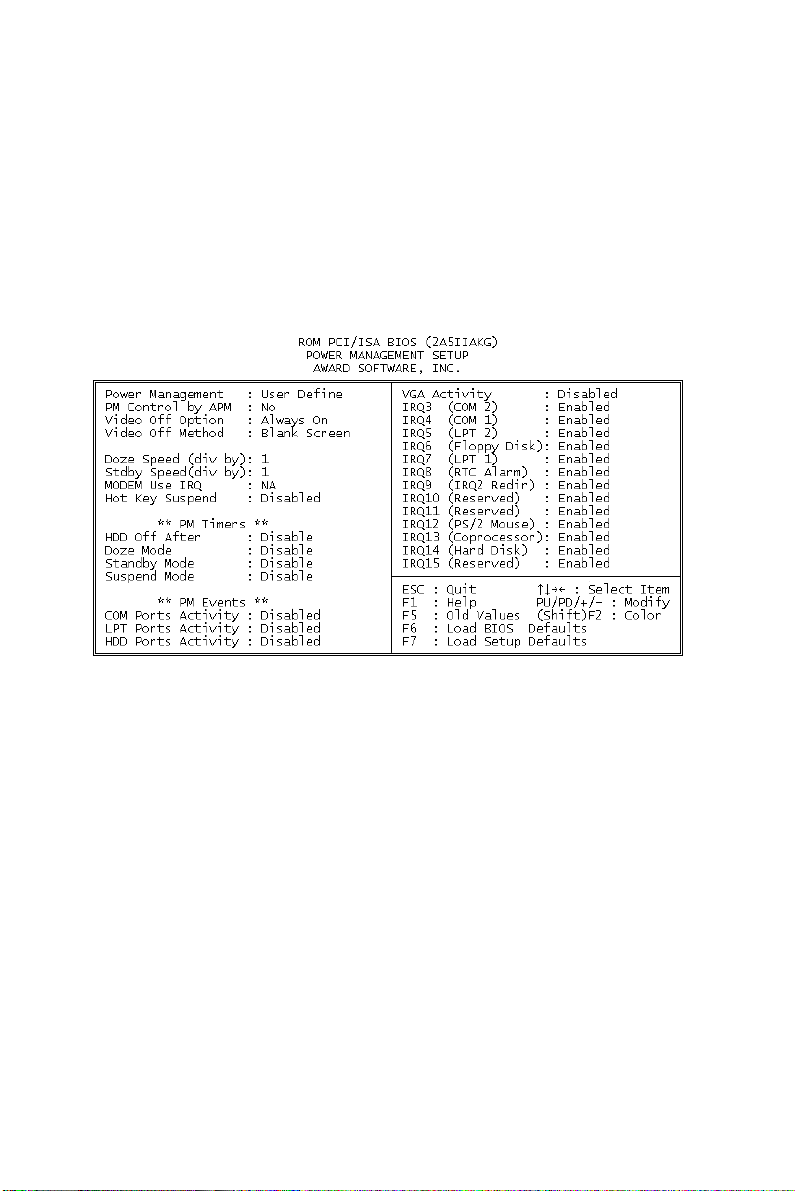
4.2.5 Power management setup
By choosing the POWER MANAGEMENT SETUP option from
the INITIAL SETUP SCREEN menu, the screen below is
displayed. This sample screen contains the manufacturer’s default
values for the PCM-5864/L.
Figure 4-5: Power management setup
Chapter 4 Award Bios Setup 53
Page 65
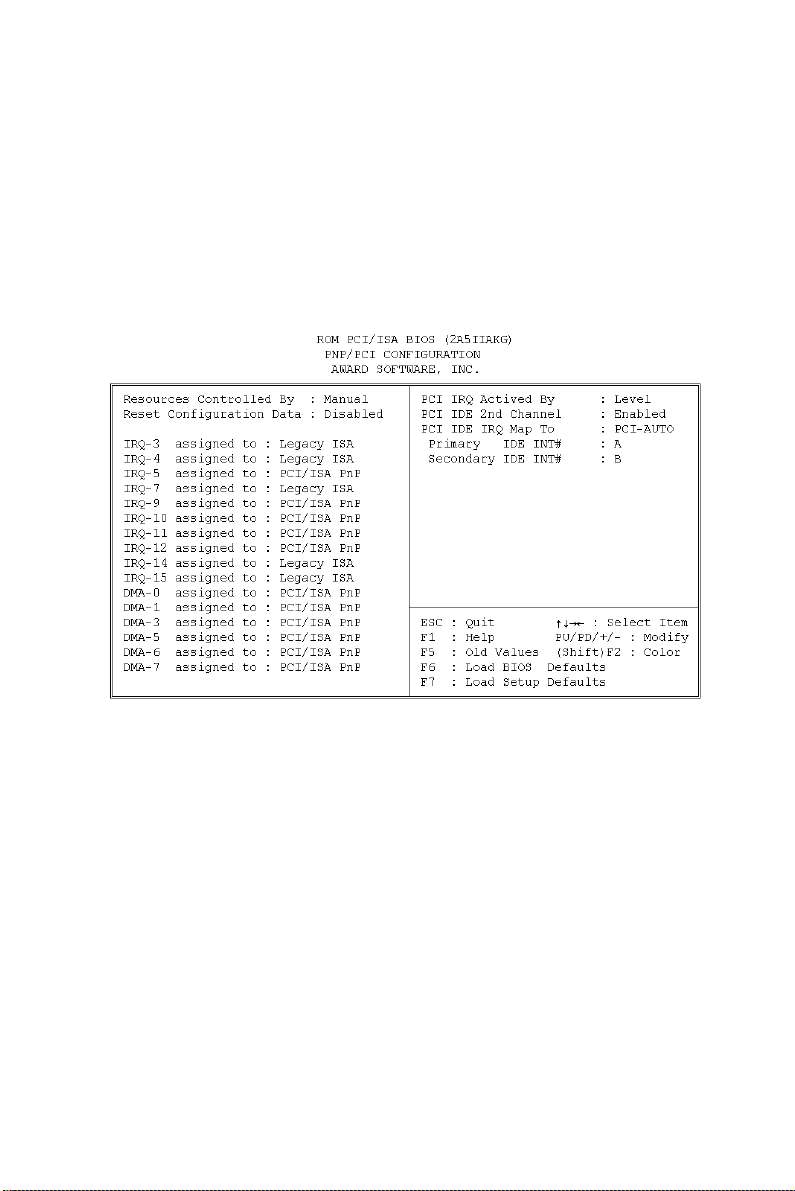
4.2.6 PnP/PCI configuration
By choosing the PnP/PCI CONFIGURATION option from the
Initial Setup Screen menu, the screen below is displayed. This
sample screen contains the manufacturer’s default values for the
PCM-5864/L.
Figure 4-6: PnP/PCI configuration
54 PCM-5864/L User's Manual
Page 66
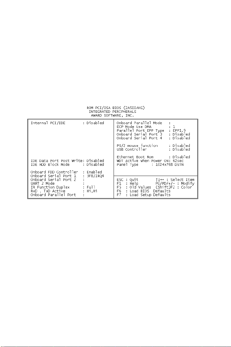
4.2.7 Integrated peripherals
By choosing the INTEGRATED PERIPHERALS option from the
INITIAL SETUP SCREEN menu, the screen below is displayed.
This sample screen contains the manufacturer’s default values for
the PCM-5864/L. By default, the PANEL TYPE supports an
18-bit 640 x 480 TFT LCD panel display.
Figure 4-7: Integrated peripherals
Chapter 4 Award Bios Setup 55
Page 67
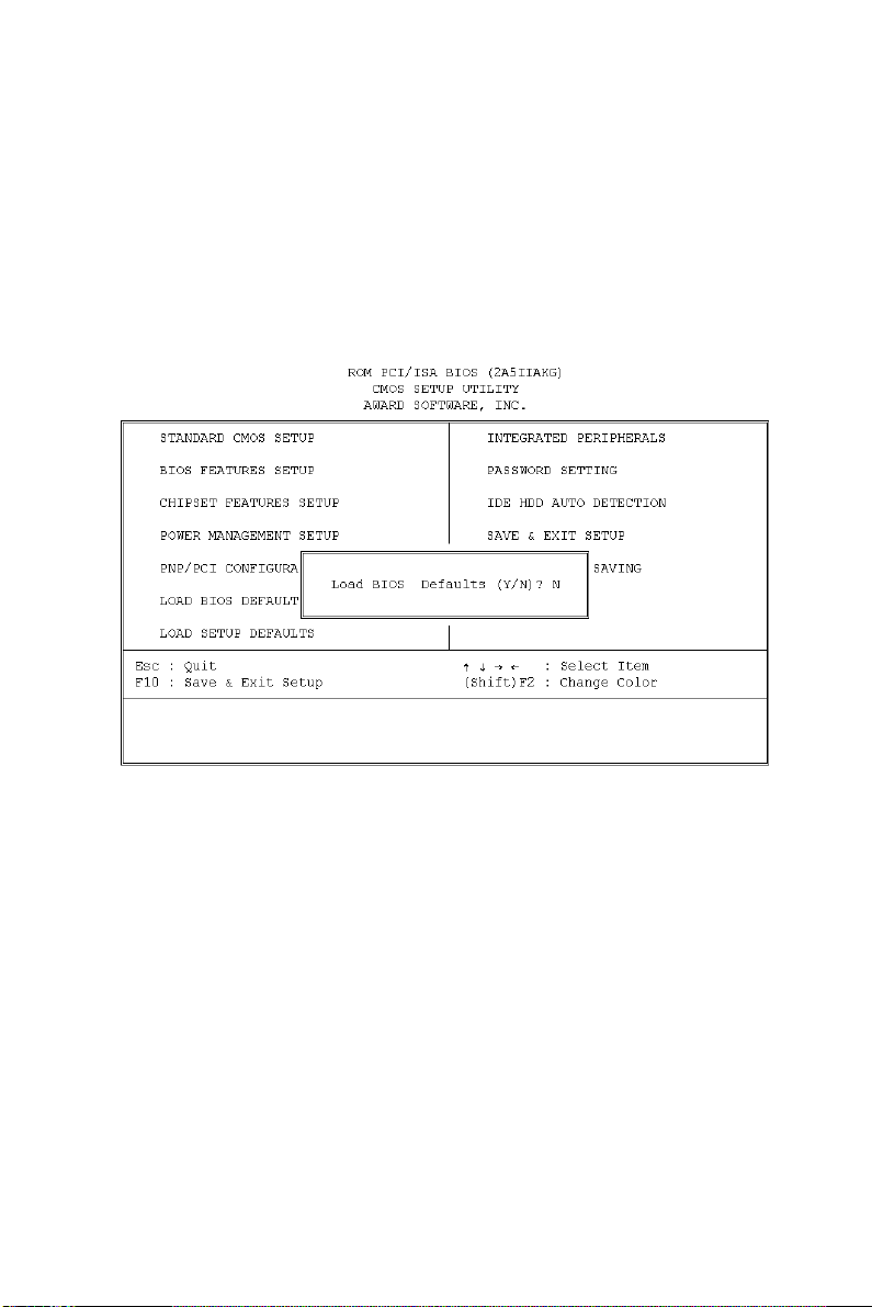
4.2.8 Load BIOS defaults
LOAD BIOS DEFAULTS loads the default system values directly
from ROM. If the stored record created by the Setup program
becomes corrupted (and therefore unusable), these defaults will
load automatically when you turn the PCM-5864/L on.
Figure 4-8: Load BIOS defaults screen
56 PCM-5864/L User's Manual
Page 68

4.2.9 Change password
To change the password, choose the PASSWORD SETTING
option form the Setup main menu and press <Enter>.
1. If the CMOS is bad or this option has never been used, a
default password is stored in the ROM. The screen will display
the following messages:
Enter Password:
Press <Enter>.
2. If the CMOS is good or this option has been used to change the
default password, the user is asked for the password stored in
the CMOS. The screen will display the following message:
Confirm Password:
Enter the current password and press <Enter>.
3. After pressing <Enter> (ROM password) or the current
password (user-defined), you can change the password stored
in the CMOS. The password can only be eight (8) characters
long at most.
Remember - to enable this feature, you must first select either
Setup or System in BIOS FEATURES SETUP.
Chapter 4 Award Bios Setup 57
Page 69
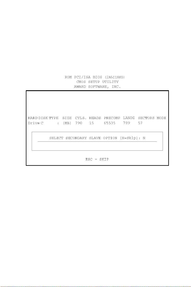
4.2.10 Auto detect hard disk
The IDE HDD AUTO DETECTION utility can automatically
detect the IDE hard disk installed in your system. You can use it to
self-detect and/or correct the hard disk type configuration.
Figure 4-9: IDE HDD auto detection screen
4.2.11 Save & exit setup
If you select this option and press <Enter>, the values entered in
the setup utilities will be recorded in the chipset’s CMOS memory.
The microprocessor will check this every time you turn your
system on, and compare this to what it finds as it checks the
system. This record is required for the system to operate.
4.2.12 Exit without saving
Selecting this option and pressing <Enter> lets you exit the Setup
program without recording any new values or changing old ones.
58 PCM-5864/L User's Manual
Page 70

PCI SVGA Setup
• Introduction
• Installation of SVGA driver for
- Windows 3.1
- Windows 95
- Windows NT
• Further information
CHAPTER
5
Page 71

5.1 Before you begin
To facilitate the installation of the enhanced display device drivers
and utility software, you should read the instructions in this
chapter carefully before you attempt installation. The enhanced
display drivers for the PCM-5864/L board are located on the
software installation disk. You must install the drivers and utility
software by using the supplied SETUP program for DOS drivers.
Note: The files on the software installation disk are
compressed. Do not attempt to install the drivers
by copying the files man ually. You must use the
supplied SETUP program to install the drivers.
Before you begin, it is important to note that most display drivers
need to have the relevant software application already installed in
the system prior to installing the enhanced display drivers. In
addition, many of the installation procedures assume that you are
familiar with both the relevant software applications and operating
system commands. Review the relevant operating system
commands and the pertinent sections of your application
software's manual before performing the installation.
5.2 Introduction
The PCM-5864/L has an on-board PCI flat panel/VGA interface.
The specifications and features are described as follows:
5.2.1 Chipset
The PCM-5864/L uses a C&T 6900/69030 chipset for its
PCI/SVGA controller. It supports many popular LCD, EL, and gas
plasma flat panel displays, aa well as conventional analog CRT
monitors. The 6900/69030 VGA BIOS supports monochrome
LCD, EL, color TFT and STN LCD flat panel displays. In
addition, it also supports interlaced and non-interlaced analog
monitors (color and monochrome VGA) in high-resolution modes,
while maintaining complete IBM VGA compatibility. Digital
monitors (i.e. MDA, CGA, and EGA) are NOT supported.
60 PCM-5864/L User's Manual
Page 72

Multiple frequency (multisync) monitors are handled as if they
were analog monitors.
5.2.2 Display memory
With on-board 2 MB display memory, the VGA controller can
drive CRT displays or color panel displays with resolutions up to
1024 x 768 @ 64 K colors. With C&T 69030, the display memory
can be expanded to 4 MB for true-color resolution of 1024 x 768.
5.2.3 Display types
CRT and panel displays can be used simultaneously. The
PCM-5864/L can be set in one of three configurations: on a CRT,
on a flat panel display, or on both simultaneously. The system is
initially set to simultaneous display mode. The CD utility disc
includes three *.COM files in the subdirectory
Biscuit\5864\Utility which can be used to configure the display.
In order to use these configuration programs, type the file name
and path at the DOS prompt.
CT.COM: Enables CRT display only
FP.COM: Enables panel display only
SM.COM: Enables both displays simultaneously
5.3 Installation of SVGA driver
Complete the following steps to install the SVGA driver. Follow
the procedures in the flow chart that apply to the operating system
that you are using within your PCM-5864/L.
Important: The f ollowing windows illustrations are e xamples
only. You must follow the flow chart instructions
and pay attention to the instructions which then
appear on your screen.
Note: <Enter> means pressing the “Enter” key on the
keyboard.
Chapter 5 PCI SVGA Setup 61
Page 73
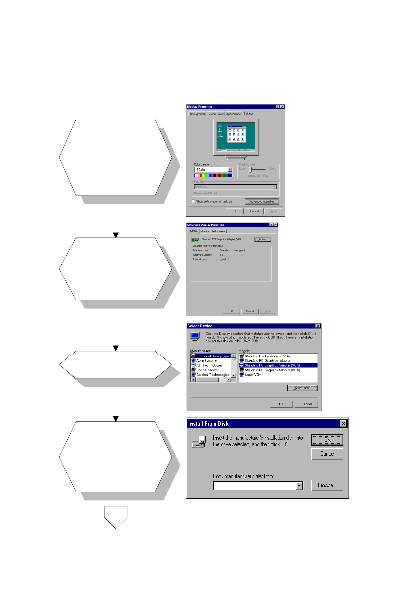
1.
2.
5.3.1 Installation for Windows 95/98
a. Select "Start",
"Settings",
"Control Panel",
"Display",
"Settings".
b. Press "Advanced
Properties".
a. Choose the
"Adapter" label.
b. Press the
"Change..."
button.
3.
4.
a. Press the "Have
Disk" button.
Insert the utility
a.
a. Insert the disc
disk into the floppy
into the CD-ROM
disk drive.
drive.
Type: "D:\Biscuit\
b.
b. Type
5864\Video.100\
"D:\VGA\Win95\".
69000W95."
c. Press "OK".
Press "OK".c.
62 PCM-5864/L User's Manual
D:\Biscuit\5864\Video.100\69000\W95\
D:\VGA\Win95\
Page 74
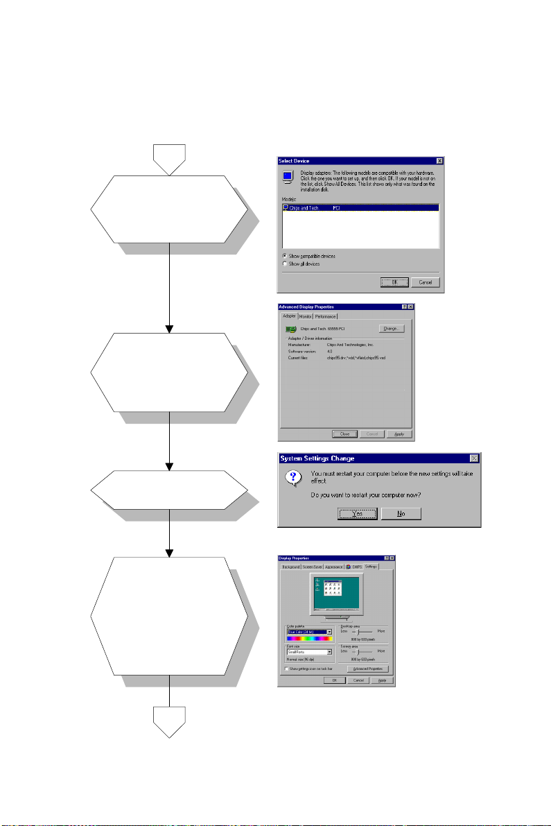
5.
6.
a. Select the
highlighted item.
b. Click the "OK"
button.
a. C&T69000/69030
appears in the
adapter label.
b. Click the "Apply"
button.
69000
7.
8.
a. Press "Yes" to
reboot.
a. Repeat Step 1 on
the previous page
of this manual.
The "CHIPS"
label appears in
"Display".
b. Adjust resolution
and color.
Chapter 5 PCI SVGA Setup 63
Page 75
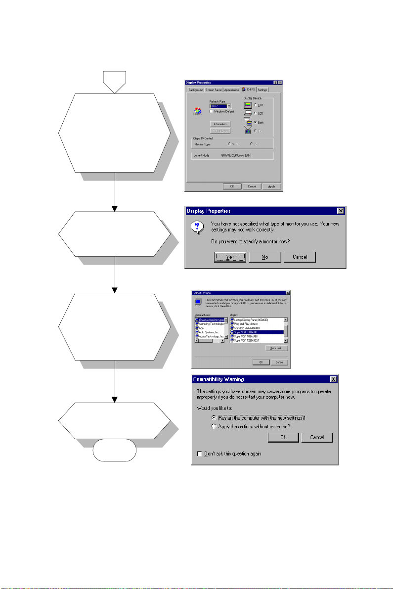
9.
10.
11.
a. Click the "CHIPS"
label.
b. Adjust the refresh
rate and display
type.
c. Press "OK" to
exit.
a. Press "Yes" to
set the monitor
type.
a. Select
"Standard",
"Super VGA 800
x 600", or "XGA".
b. Press the "OK"
button.
[7]
12.
a. Choose "Restart"
to reboot.
END
Note: 1. In step 4, for Windows 98, the path is:
64 PCM-5864/L User's Manual
"D:\Biscuit\5864\Video.100\69000\Win98\"
2. In step 4, f or the 4 MB VGA version, the path is:
"D:\Biscuit\5864\Video.100\69030\"
Page 76
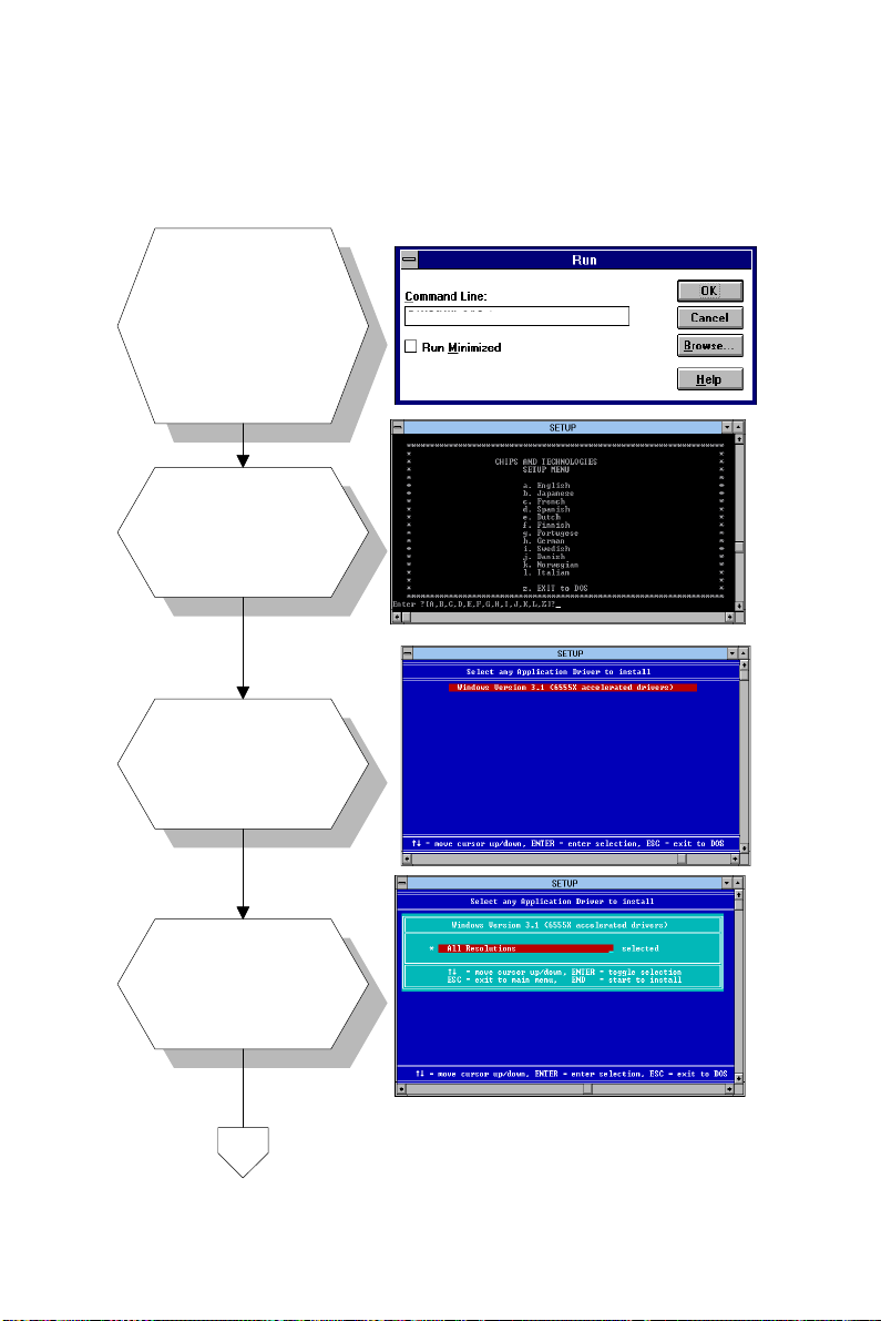
1.
2.
3.
5.3.2 Installation for Windows 3.1
a.
Insert the utility
a. Insert the disc
disk into the floppy
into the CD-ROM
disk drive.
drive.
b.
Select "File" in
b. Select "File" in
Program Manager.
Program Manager.
Click "Run" and type:
c.
c. Click "Run" and
"D:\Biscuit\5864\
type: "D:\VGA\
Video.100\69000\
Win31\Setup.exe".
Win31\Setup.exe".
a. Choose the
language you want
to use during
installation.
a. Select the
highlighted item.
b. Press "ENTER".
D:\VGA\Win31\Setup.exe
D:\Biscuit\5864\Video.100\69000\Win31\Setup.exe
4.
a. Press "ENTER" to
install all
resolutions.
Chapter 5 PCI SVGA Setup 65
Page 77
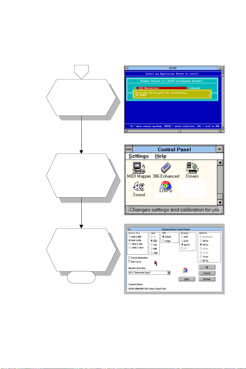
5.
6.
7.
a. Type the path of
the operating
system.
a. When installation
is completed,
reboot the system.
b. You will see the
"ChipsCPL" icon in
the control panel.
a. Double click
"ChipsCPL".
b. Adjust screen size,
color and refresh
rate to your
preferences.
ChipsCPL
END
66 PCM-5864/L User's Manual
Page 78
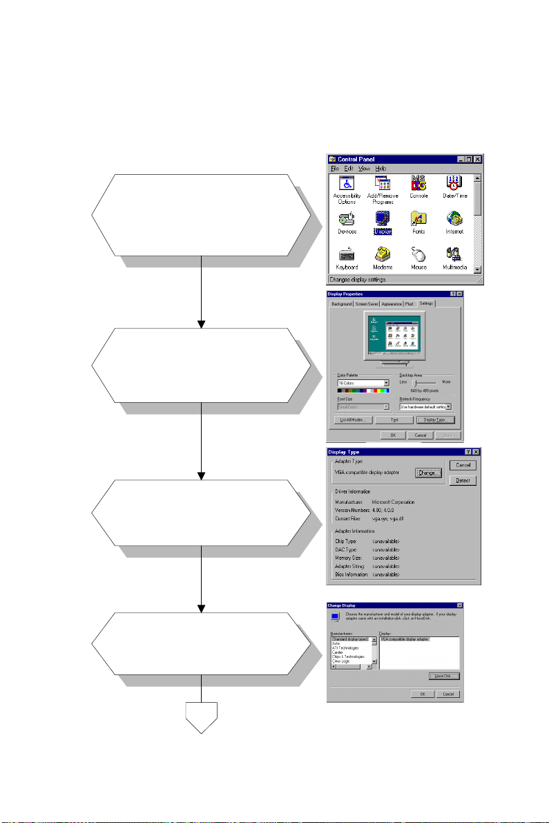
5.3.3 Installation for Windows NT
a. Select "Start", "Settings",
1.
2.
"Control Panel".
b. Double click the "Display"
icon.
a. Choose the "Settings" label.
b. Press the "Display Type"
button.
3.
4.
a. Press the "Change..." button.
a. Click the "Have Disk..."
button.
Chapter 5 PCI SVGA Setup 67
Page 79
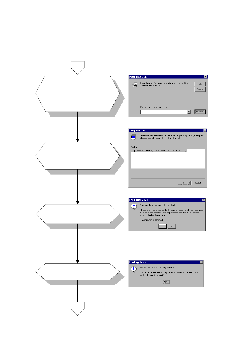
5.
6.
Insert the utility disk into
a.
a. Insert the disc into the
the floppy disk drive.
CD-ROM drive.
Type: "D:\Biscuit\5864\
b.
b. Type "D:\VGA\NT40\" in
69000\Video.100\Nt40\".
the blank.
c. Press the "OK" button.
a. Select the highlighted
item.
b. Press the "OK" button.
D:\VGA\NT40\
D:\Biscuit\5864\69000\Video.100\Nt40\
7.
8.
a. Press "Yes" to proceed.
a. Press "OK" to reboot.
68 PCM-5864/L User's Manual
Page 80
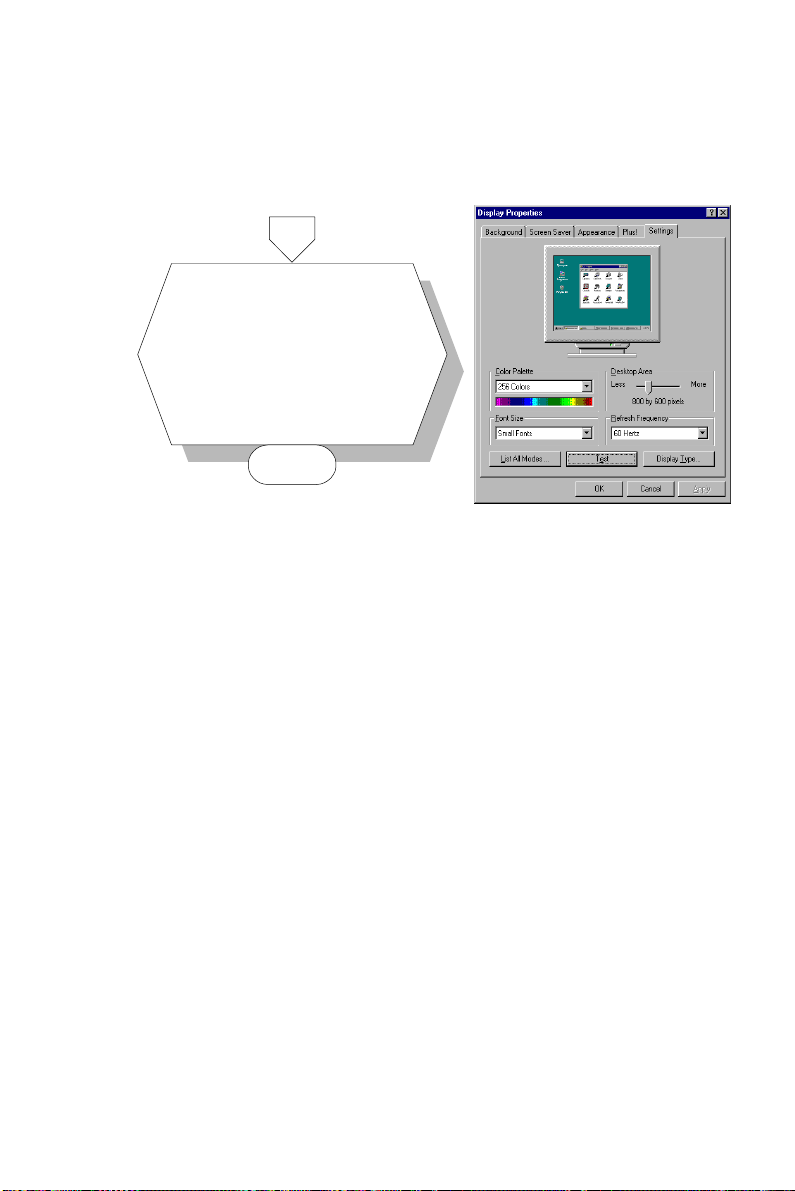
9.
a. Repeat Step 1 in this
manual, to select the
"Settings" label.
b. Adjust resolution and color.
c. Click "Test" to see the
result.
d. Click "OK" to save the
setting.
END
Chapter 5 PCI SVGA Setup 69
Page 81

5.4 Further information
For further information about PCI/SVGA installation in your
PCM-5864/L, including driver updates, troubleshooting guides
and FAQ lists, visit the following web resources:
C&T website: www.chips.com
EMAC's Website at: http:\\www.emacinc.com
70 PCM-5864/L User's Manual
Page 82

CHAPTER
6
Video
• Introduction
• Installation of video capture driver for
Windows 95/98
Page 83

6.1 Introduction
The PCM-5864/L's on-board Video-in and Video-out (TV-out)
provides NTSC and PAL video standards. Video-in uses Philips
SAA 7111A video input processor. TV-out uses Analog Device
725AR. Video-in provides an 8-pin header connector for S-video.
Alternatively, an optional cable kit provides an RCA yellow jack
for composite video input (see Appendix E). Video-out provides a
6-pin header connector for S-video. Alternatively, an optional
cable kit provides an RCA yellow jack for composite video output
(see Appendix E).
6.2 Installation of video driver
Before installing the Video-in driver, please take note of the
procedures detailed below. You must know which operating
system you are using in your PCM-5864/L, and then refer to the
corresponding installation flow chart. Just follow the steps in the
flow chart. You can quickly and successfully complete the
installation, even if you are not familiar with instructions for
Windows.
Note: The CD-ROM drive is designated as "D" through-
out this chapter.
72 PCM-5864/L User's Manual
Page 84
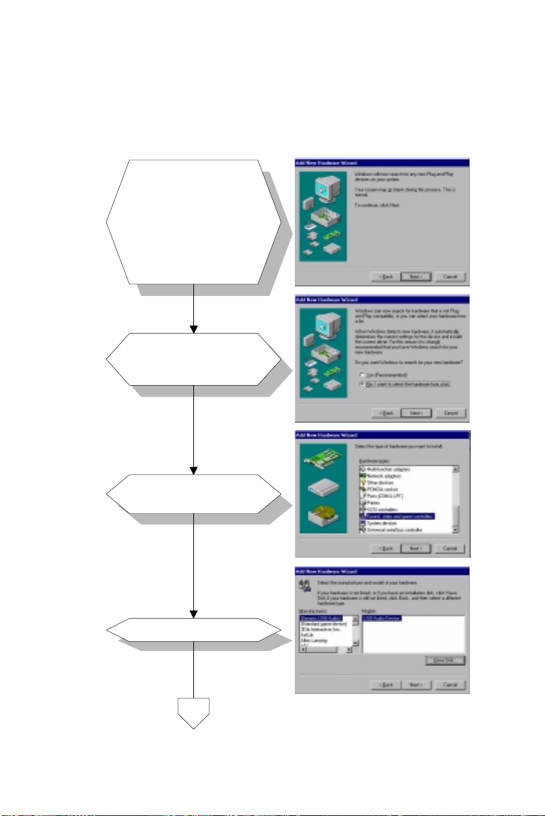
6.2.1 Installation for Windows 95/98
a. Select "Start",
"Settings", "Control
Panel", "Add New
1.
2.
Hardware".
b. Click "Next" to begin
installing the new device.
c. Click "Next" to
continue.
Choose "No, I want to
a.
select hardware....".
b. Click "Next".
3.
4.
a. Select "Sound, video,..".
Click "Next".b.
a. Click "Have Disk...".
Chapter 6 Video 73
Page 85
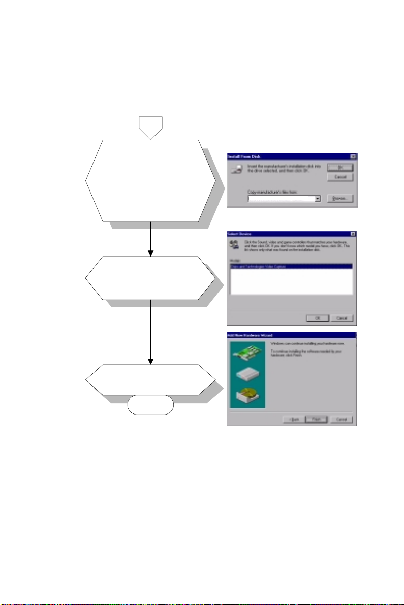
5.
6.
7.
a. Insert the disk into the
CD-ROM drive.
b. Type the correct path:
"D:\Biscuit\5864\
Video.100\69000\
Capture".
c.
Click the "OK" button.
a.
Select the highlighted
item.
Click "OK".b.
a.
Click "Finish" to
complete.
END
D:\Biscuit\5864\Video.100\69000\Capture
Note: Bef ore y ou restart Windows , insert the following
pcvideo.ini and ctmmhw.ini files into the Windows
directory:
[GPIO]
GPIO_SDA=0
GPIO_SCL=1
74 PCM-5864/L User's Manual
Page 86
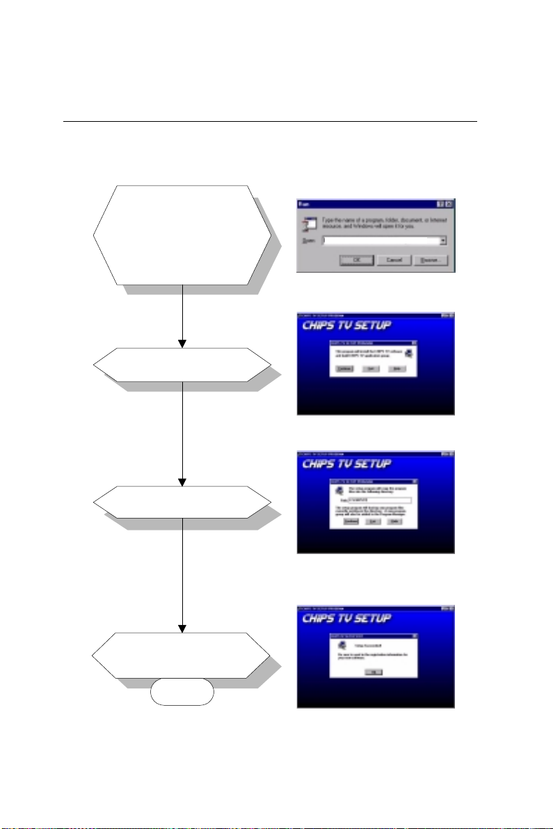
6.3 Installation of Chips-TV utility
This utility is for demonstration only.
a. Select "Start", "Run".
Type the correct path:
b.
1.
"D:\Biscuit\5864\
Video.100\69000\
Chips-TV\Setup.exe".
c. Click the "OK" button.
D:\Biscuit\5864\Video.100\69000\Chips-TV\Setup.exe
2.
3.
4.
a. Click "Continue".
a. Click "Continue".
a. Click "OK" to complete
the setup.
END
Chapter 6 Video 75
Page 87

76 PCM-5864/L User's Manual
Page 88

Audio
• Introduction
• Installation of audio driver for
Windows 95/98/NT
CHAPTER
7
Page 89

7.1 Introduction
The PCM-5864/L on-board audio interface provides high-quality
stereo sound and FM music synthesis (ESFM) by using the
ES1373 audio controller from Creative Technology Ltd. The audio
interface can record, compress, and play back voice, sound, and
music with a built-in mixer control. The PCM-5864/L's on-board
audio interface also supports the Plug and Play (PnP) standard and
provides PnP configuration for audio, FM, and MPU-104 logical
devices. It is compatible with AC97 version 2.0, voice, and music
functions. The ESFM synthesizer is register compatible with the
OPL3 and has extended capabilities.
7.2 Installation of audio driver
Before installing the audio driver, please take note of the procedures detailed below. You must know which operating system you
are using in your PCM-5864/L, and then refer to the corresponding installation flow chart. Just follow the steps in the flow chart.
You can quickly and successfully complete the installation, even
though you are not familiar with instructions for Windows.
Note: The CD-ROM drive is designated as "D" through-
out this chapter.
78 PCM-5864/L User's Manual
Page 90
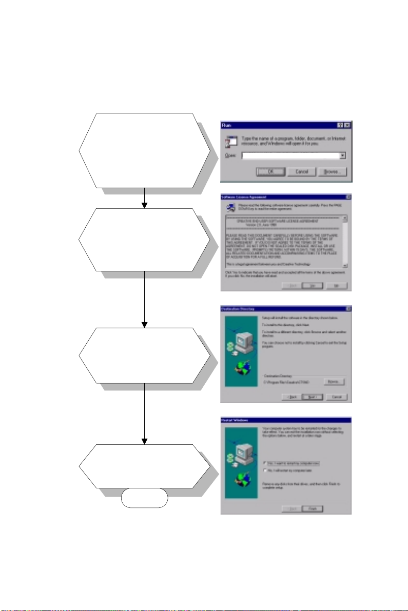
7.2.1 Installation for Windows 95/98/NT
a. Select "Start", "Run".
Type the correct path:
b.
1.
2.
3.
"D:\Biscuit\5864\
Audio.100\Driver\
Setup\Setup.exe".
c. Click the "OK" button.
a.
Click "Yes" to accept
the agreement.
b.
On the next page,
read the Readme file
and click "Next".
a. Click "Next" to continue.
b. Follow the procedure
which appears on your
screen.
D:\Biscuit\5864\Audio.100\Driver\Setup\Setup.exe
4.
a.
After installation, select
"Yes" and click "Finish"
to restart the computer.
END
Chapter 7 Audio 79
Page 91

80 PCM-5864/L User's Manual
Page 92

CHAPTER
8
PCI Bus Ethernet
Interface
This chapter provides information on
Ethernet configuration.
• Introduction
• Installation of Ethernet driver for
- MS-DOS
- Windows 3.1
- Windows 95
- Windows 98
- Windows NT
• Further information
Page 93

8.1 Introduction
The PCM-5864/L is equipped with a high-performance 32-bit
Ethernet chipset which is fully compliant with IEEE 802.3 100
Mbps CSMA/CD standards. It is supported by major network
operating systems. It is also both 100Base-T and 10Base-T
compatible. The medium type can be configured via the
82558.exe program included on the utility disk.
The Ethernet port provides a standard RJ-45 jack. The network
boot feature can be utilized by incorporating the boot ROM image
files for the appropriate network operating system. The boot ROM
BIOS files are combined with system BIOS, which can be
enabled/disabled in the BIOS setup.
8.2 Installation of Ethernet driver
Before installing the Ethernet driver, note the procedures below.
You must know which operating system you are using in your
PCM-5864/L, and then refer to the corresponding installation flow
chart. Then just follow the steps described in the flow chart. You
will quickly and successfully complete the installation, even if you
are not familiar with instructions for MS-DOS or WINDOWS.
Note: The windows illustrations in this chapter are
examples only. You must follow the flow chart
instructions and pay attention to the instructions
which then appear on your screen.
8.2.1 Installation for MS-DOS and Windows 3.1
If you want to set up your Ethernet connection under the MS-DOS
or Windows 3.1 environment, you should first check your server
system model. For example, MS-NT, IBM-LAN server, and so on.
Then choose the correct driver to install in your panel PC.
The installation procedures for various servers can be found on
CD-ROM. The file path begins as:
D:\Biscuit\5864\Lan.100\8139A\wfw311
82 PCM-5864/L User's Manual
Page 94
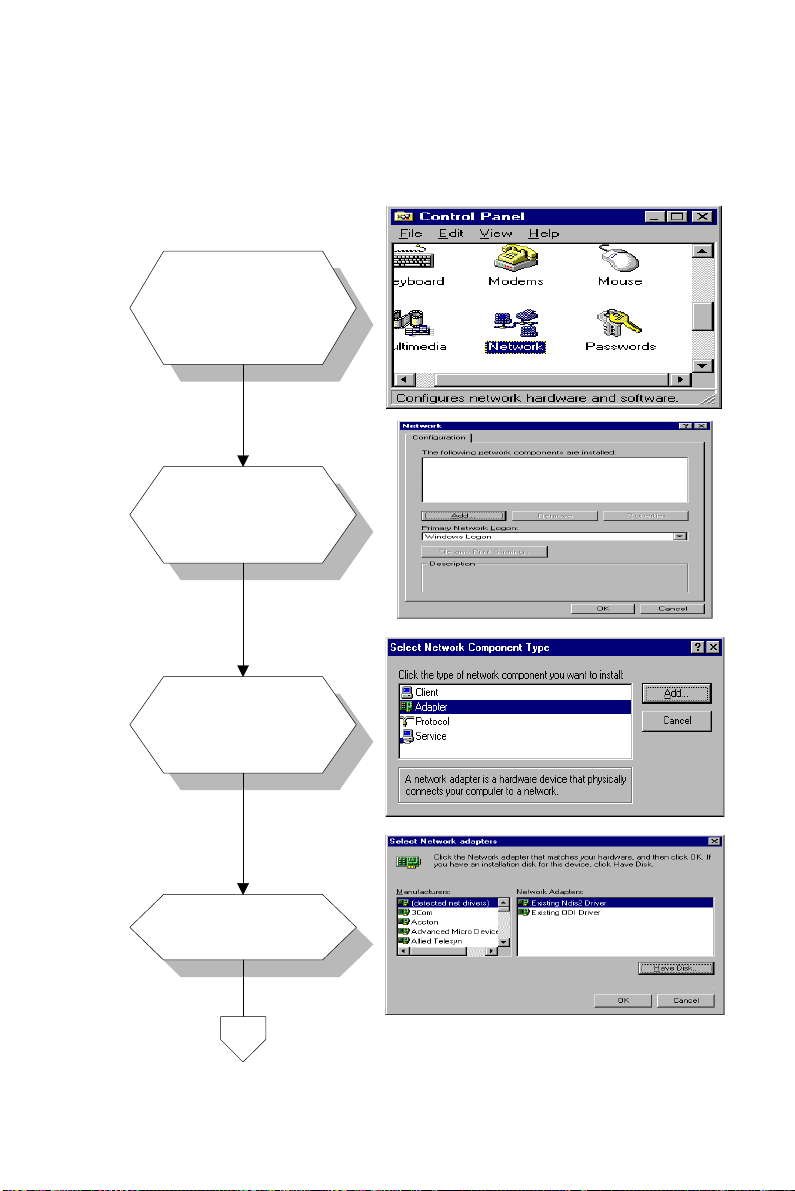
8.2.2 Installation for Windows 95
a. Select "Start",
"Settings",
1.
2.
3.
"Control Panel".
b. Double click
"Network".
a. Click "Add" and
prepare to install
network functions.
a. Select the
"Adapter" item to
add the Ethernet
card.
4.
a. Click "Have Disk"
to install the driver.
Chapter 8 PCI Bus Ethernet Interface 83
Page 95
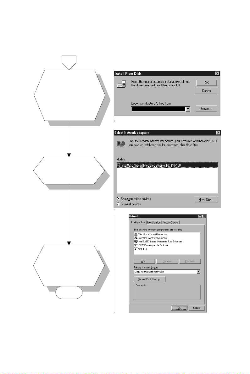
5.
6.
7.
Insert the disc
a.
Insert the CD into
a.
labeled "RTL8139A
the D: drive.
Driver #2" into drive
Fill in:
b.
A:.
"D:\Biscuit\5864\
Lan.100\8139A\
b. Fill in the correct
Win95".
path.
c. Click "OK".
a. Choose the
"Realtek" item.
b. Click "OK".
a. Make sure the
configurations of
relative items are
set correctly.
b. Click "OK" to
reboot.
D:\Biscuit\5864\Lan.100\8139A\Win95
END
Note: The correct file path for Windows 98 is:
D:\Biscuit\5864\Ethernet.100\Win98
84 PCM-5864/L User's Manual
Page 96
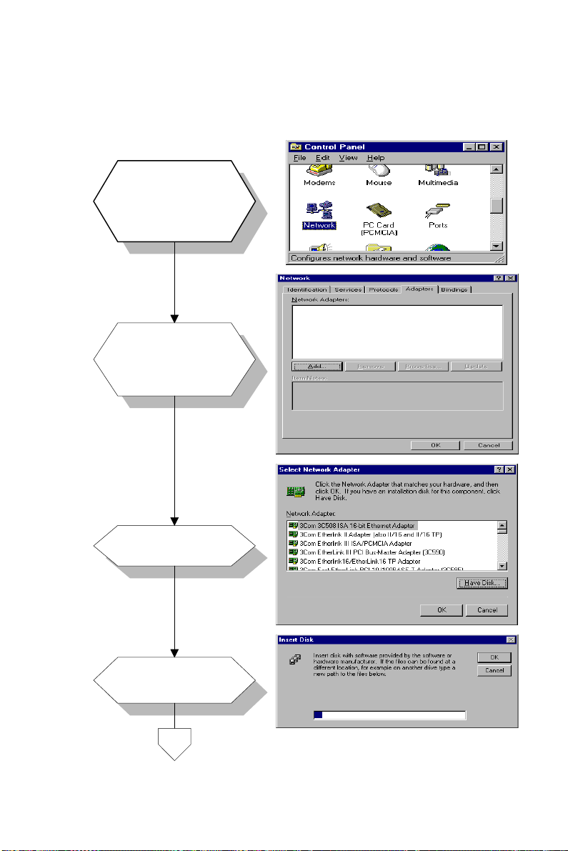
8.2.3 Installation for Windows NT
a. Select "Start",
"Settings",
1.
2.
"Control Panel".
b. Double click
"Network".
a. Choose the
"Adapters" label.
b. Click the "Add"
button.
3.
4.
a. Press "Have
Disk".
a. Type "D:".
b. Press "OK".
D:
Chapter 8 PCI Bus Ethernet Interface 85
Page 97
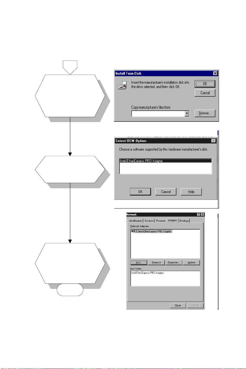
5.
6.
7.
a.
Insert the CD into
a. Insert the disc into
the D: drive.
the CD-ROM drive.
Fill in: "D:\Biscuit\
b.
b. Fill in the correct
5864\Lan.100\
path.
8139A\Winnt".
c. Press the "OK"
c. Press the "OK"
button.
button.
a. Choose the
"Realtek" item.
b. Press the "OK"
button.
a. Make sure the
configurations of
relative items are
set correctly.
b. Press the "OK"
button to reboot.
D:\Biscuit\5864\Lan.100\8139A\Winnt
D:\Lan\
END
86 PCM-5864/L User's Manual
Page 98

8.3 Further information
Realtek website: www.realtek.com
EMAC's website: www.emacinc.com
Chapter 8 PCI Bus Ethernet Interface 87
Page 99

88 PCM-5864/L User's Manual
Page 100

APPENDIX
A
Programming the
Watchdog Timer
The PCM-5864/L is equipped with
a watchdog timer that resets the CPU or
generates an interrupt if processing comes
to a standstill for any reason. This
feature ensures system reliability in
industrial standalone or unmanned
environments.
 Loading...