

Page 1

Installation Guide
iR1600 Rugged Modem
iR1600 GPS-Enabled Modem
Page 2

Installation Guide
TABLE OF CONTENTS
TABLE OF FIGURES .......................................................................................................................................................................... 1
FCC COMPLIANCE............................................................................................................................................................................. 3
REQUIRED COMPONENTS................................................................................................................................................................ 5
Box Contents ................................................................................................................................................................................................... 5
Documentation ...................................................................................................................................................................................................... 6
Required Components for Installation (sold separately) ................................................................................................................................. 6
Components for Mobile Environment (sold separately) ........................................................................................................................................ 7
Components for Fixed Environment (sold separately) .......................................................................................................................................... 7
Approved Components List ................................................................................................................................................................................... 7
How to Order Components.................................................................................................................................................................................. 11
Required Components for Operation............................................................................................................................................................... 9
iDEN Packet Data Applet .................................................................................................................................................................................... 9
Data Account Activation ........................................................................................................................................................................................ 9
INTRODUCTION ............................................................................................................................................................................... 11
Nextel Coverage .......................................................................................................................................................................................... 11
Nextel Customer Care ................................................................................................................................................................................. 11
PRODUCT OVERVIEW ..................................................................................................................................................................... 13
General Overview .......................................................................................................................................................................................... 13
Modem Characteristics .................................................................................................................................................................................. 14
Modem Operating Modes .............................................................................................................................................................................. 15
Data Connections .......................................................................................................................................................................................... 15
Modem Types ................................................................................................................................................................................................ 15
Modem Components ........................................................................................................................................................................................... 16
Front Panel Views................................................................................................................................................................................................................. 16
Rear Panel Views ................................................................................................................................................................................................................. 17
Modem Technical Specifications ................................................................................................................................................................... 18
INSTALLATION PREPARATION...................................................................................................................................................... 21
Before You Start Installing ............................................................................................................................................................................. 21
Installation Planning....................................................................................................................................................................................... 21
Planning Modem Location................................................................................................................................................................................... 22
Modem Dimensions.............................................................................................................................................................................................................. 23
Table of Dimensions............................................................................................................................................................................................................. 24
Planning Antenna Location ................................................................................................................................................................................. 24
Planning Cable Layout ........................................................................................................................................................................................ 25
Serial Cable Routing............................................................................................................................................................................................ 25
Page 3

Installation Guide
Installation Tools.................................................................................................................................................................................................. 25
MOBILE INSTALLATION.................................................................................................................................................................. 27
Installation Steps............................................................................................................................................................................................ 27
Mounting the Modem ..................................................................................................................................................................................... 28
Select Modem Location ....................................................................................................................................................................................... 28
Mount the Modem................................................................................................................................................................................................ 28
Mounting the Antenna(s) ............................................................................................................................................................................... 29
Approved Antennas (sold separately) ................................................................................................................................................................. 29
Select Antenna Location ..................................................................................................................................................................................... 29
Mount the Antenna(s) .......................................................................................................................................................................................... 30
Mount Modem Antenna......................................................................................................................................................................................................... 30
Mount GPS Antenna (optional)............................................................................................................................................................................................. 30
Route and Connect Cables ................................................................................................................................................................................. 31
Approved Power Cable (sold separately)..............................................................................................................................................................................31
Route and Connect Ignition/Power...................................................................................................................................................................... 32
Route and Connect Antenna Cable(s) ................................................................................................................................................................ 33
Route and Connect Data Cable(s) – sold separately.......................................................................................................................................... 33
Serial Connector (DB9) Pinouts............................................................................................................................................................................................ 33
Other Mobile Installation Configurations........................................................................................................................................................ 34
Continuous Power Configuration......................................................................................................................................................................... 34
Mounting the Modem............................................................................................................................................................................................................ 35
Mounting the Antenna(s)....................................................................................................................................................................................................... 35
Route and Connect Ignition/Power ....................................................................................................................................................................................... 35
Route and Connect Antenna Cable(s) .................................................................................................................................................................................. 36
Route and Connect Data Cable(s)........................................................................................................................................................................................ 36
Docking Station Configuration............................................................................................................................................................................. 37
Mounting the Modem............................................................................................................................................................................................................ 37
Mounting the Antenna(s)....................................................................................................................................................................................................... 37
Route and Connect Ignition/Power ....................................................................................................................................................................................... 37
Route and Connect Antenna Cable(s) .................................................................................................................................................................................. 38
Route and Connect Data Cable(s)........................................................................................................................................................................................ 38
FIXED INSTALLATION ..................................................................................................................................................................... 39
Installation Steps............................................................................................................................................................................................ 39
Mounting the Modem ..................................................................................................................................................................................... 40
Select Modem Location ....................................................................................................................................................................................... 40
Mount the Modem................................................................................................................................................................................................ 40
Mounting the Antenna(s) ............................................................................................................................................................................... 40
Approved Antennas – sold separately ................................................................................................................................................................ 41
Select Antenna Location ..................................................................................................................................................................................... 41
Mount the Antenna(s) .......................................................................................................................................................................................... 41
Mount Modem Antenna......................................................................................................................................................................................................... 41
Page 4

Installation Guide
Mount GPS Antenna (optional)............................................................................................................................................................................................. 41
Route and Connect Cables............................................................................................................................................................................ 42
Approved Cables – sold separately..................................................................................................................................................................... 43
Route and Connect Ignition/Power Cable ........................................................................................................................................................... 43
Route and Connect Antenna Cable(s) ................................................................................................................................................................ 43
Route and Connect Data Cable(s) ...................................................................................................................................................................... 43
Serial Connector (DB9) Pinouts............................................................................................................................................................................................ 44
CONNECTING I/O DEVICES............................................................................................................................................................. 45
Connector Pinouts ......................................................................................................................................................................................... 45
I/O Wiring Options.......................................................................................................................................................................................... 47
Wiring Options for Analog Inputs......................................................................................................................................................................... 47
Wiring Options for Digital Inputs.......................................................................................................................................................................... 48
VERIFYING INSTALLATION............................................................................................................................................................. 51
Communication Indicators ............................................................................................................................................................................. 51
iDEN Network Status Indicators........................................................................................................................................................................ 52
Packet Data ..........................................................................................................................................................................................................................53
Circuit Switched Data............................................................................................................................................................................................................ 53
Signal Status Indicators....................................................................................................................................................................................... 53
Operating Mode Indicators .................................................................................................................................................................................. 54
Verify Mobile Installation................................................................................................................................................................................ 54
Power up the Modem .......................................................................................................................................................................................... 55
Verify Communications ....................................................................................................................................................................................... 55
Verify Fixed Installation.................................................................................................................................................................................. 55
Power up the Modem .......................................................................................................................................................................................... 55
Verify Communications ....................................................................................................................................................................................... 55
CONFIGURING THE MODEM........................................................................................................................................................... 57
TROUBLESHOOTING....................................................................................................................................................................... 59
Common Problems ........................................................................................................................................................................................ 59
Connect to Diagnostic Port ............................................................................................................................................................................ 61
Set up HyperTerminal Session...................................................................................................................................................................... 61
Modem Diagnostic Menu ............................................................................................................................................................................... 64
Unsolicited Firmware Updates....................................................................................................................................................................... 67
SAFETY NOTICE .............................................................................................................................................................................. 69
APPENDIX A: GLOSSARY............................................................................................................................................................... 71
INDEX................................................................................................................................................................................................ 77
Page 5
Installation Guide
IMPORTANT!
Please Read Safety Notice on Page 69 before using the iR1600 Modem.
RFM-6000-5015 Rev 1
June 2004
© 2004 Nextel Communications, Inc. NEXTEL and the NEXTEL logo are registered trademarks owned by Nextel Communications, Inc. All other product or
service names are the property of their respective owners. All trademarks service marks, and trade names are protected by state, federal and/or international
trademark laws. All rights reserved.
Page 6

TABLE OF FIGURES
Installation Guide
Figures Page
Figure 1 – iR1600 GPS-Enabled Modem........................................................................................................................................................13
Figure 2 – Front Panel of iR1600 GPS-Enabled Modem ..............................................................................................................................16
Figure 3 – Front Panel of iR1600 Rugged Modem.........................................................................................................................................16
Figure 4 – Rear Panel of iR1600 GPS-Enabled Modem................................................................................................................................17
Figure 5 – Rear Panel of iR1600 Rugged Modem..........................................................................................................................................17
Figure 6 – Overall view of iR1600 GPS-Enabled Modem.............................................................................................................................23
Figure 7 – iR1600 Installation Wiring Diagram (Mobile).............................................................................................................................31
Figure 8 – Modem Power Wiring Diagram ....................................................................................................................................................32
Figure 9 – Continuous Power Configuration .................................................................................................................................................35
Figure 10 – Docking Station Configuration....................................................................................................................................................37
Figure 12 – I/O Connectors on iR1600 Rear Panel........................................................................................................................................45
Figure 13 – Diagram for Connecting 4-20mA Sensors..................................................................................................................................47
Figure 14 – Diagram for Connecting 0-10V Sensors .....................................................................................................................................47
Figure 15 – Diagram for Connecting Open/Gnd Input Discrete ..................................................................................................................48
Figure 16 – Diagram for Connecting Open/Gnd Input Discrete ..................................................................................................................48
Figure 17 – Diagram for Connecting +12V/Open Input Discrete.................................................................................................................49
Figure 18 – LEDs on Front Panel of GPS-Enabled Modem .........................................................................................................................52
nextel.com
1
Page 7

Installation Guide
This page intentionally left blank.
2
nextel.com
Page 8
FCC COMPLIANCE
DECLARATION OF CONFORMITY
DECLARATION OF CONFORMITY
Responsible party name: eLutions, Inc.
Responsible party name: eLutions, Inc.
Address: 5905 Breckenridge Parkway
Address: 5905 Breckenridge Parkway
Suite F
Suite F
Tampa, FL 33610
Tampa, FL 33610
Phone number: 1-800-836-9909
Phone number: 1-800-836-9909
Hereby declares that the product:
Hereby declares that the product:
Product name: iR1600 GPS-Enabled Modem
Product name: iR1600 GPS-Enabled Modem
Model Number: 6000-C5-RFM
Model Number: 6000-C5-RFM
Product name: iR1600 Rugged Modem
Product name: iR1600 Rugged Modem
Model Number: 6100-C5-RFM
Model Number: 6100-C5-RFM
Conforms to the following regulation:
Conforms to the following regulation:
FCC Part 15, subpart B
FCC Part 15, subpart B
FCC Part 90, subpart S
FCC Part 90, subpart S
Class B Digital device
Class B Digital device
Date: March 8, 2004
Date: March 8, 2004
Note: This equipment has been tested and found to comply with the limits for a
Note: This equipment has been tested and found to comply with the limits for a
Class B digit al device, purs uant to part 15 and 90 of the FC C Rules. These l imits
Class B digit al device, purs uant to part 15 and 90 of the FC C Rules. These l imits
are designed t o provide reasonable protection against harmful interference in a
are designed t o provide reasonable protection against harmful interference in a
residential installation. The equipment generates, uses and can radiate radio
residential installation. The equipment generates, uses and can radiate radio
frequency ene rgy and, if not in stalled and used in accordance with the
frequency ene rgy and, if not in stalled and used in accordance with the
instructions, may cause har mful interfer ence to radio c ommunicatio ns. However,
instructions, may cause har mful interfer ence to radio c ommunicatio ns. However,
there is no gu arantee that int erference wil l not occur in a pa rticular insta llation.
there is no gu arantee that int erference wil l not occur in a pa rticular insta llation.
If this equipm ent does cause harmful inter ference to radi o or television reception,
If this equipm ent does cause harmful inter ference to radi o or television reception,
which can be d etermined by t urning the equi pment off and on , the user is
which can be d etermined by t urning the equi pment off and on , the user is
encouraged to try to correct th e interference or by one or mor e of the following
encouraged to try to correct th e interference or by one or mor e of the following
measures:
measures:
-- Reorient or relocate the receiving antenna.
-- Reorient or relocate the receiving antenna.
-- Increase th e separation be tween the equ ipment and rec eiver.
-- Increase th e separation be tween the equ ipment and rec eiver.
-- Connect the equipment into an outlet on a circuit different from that to
-- Connect the equipment into an outlet on a circuit different from that to
which the receiver is connected.
which the receiver is connected.
-- Consult the dealer or an experienced radio/TV technician for help.
-- Consult the dealer or an experienced radio/TV technician for help.
Per FCC CFR 47 2.989
Per FCC CFR 47 2.989
Installation Guide
nextel.com
3
Page 9

Installation Guide
This page intentionally left blank.
4
nextel.com
Page 10

Installation Guide
REQUIRED COMPONENTS
This chapter contains information about the required components for successful installation and operation of the iR1600 modem. This chapter
includes:
Box Contents
Documentation
Required Components for Installation
Components for Mobile Environment
Components for Fixed Environment
Approved Components List
How to Order Components
Required Components for Operation
Communication Software
Data Account Activation
Box Contents
Page 5
Page 6
Page 6
Page 7
Page 7
Page 8
Page 9
Page 9
Page 9
The iR1600 modem ships with the following:
• iR1600 Modem
• CD with documentation
o Installation Guide
o Configuration Guide
o Quick Reference Guide (for operators/end users)
o Warranty Card
o Getting Started - Installation and Usage Requirements
o Remote Configuration Tool Kit
Remote Configuration (Over-the-Air) Guide
nextel.com
5
Page 11
Installation Guide
Documentation
Documentation for the iR1600 consists of three guides, an Installation Guide, Configuration Guide and a Remote Configuration Guide. This
document, the iR1600 Installation Guide provides you with instructions on installing the hardware and describing how to:
• Mount the modem in a mobile environment (vehicle installation).
• Mount the modem in a fixed environment.
• Install and connect the required components (e.g. power cables, antennas, etc.).
• Connect and configure your computer and I/O devices (e.g. Remote Terminal Units (RTU), sensors, controllers, etc.).
• Verify the installation.
• Troubleshoot common installation problems.
The iR1600 Configuration Guide provides you with instructions on how to:
• Install the iDEN
• Set up Windows Components.
• Configure the modem’s operating modes.
• Configure data encryption parameters.
• Configure the Access Control List for IP Address.
• Configure BSAP protocol for translation to IP Address.
• Use AT Commands to configure the modem.
Packet Data Applet (for data services).
The iR1600 Remote Configuration Guide provides you with instructions on how to:
• Install the Over the Air Tool Kit.
• Retrieve and view remote device parameters.
• Perform remote over the air (OTA) configuration changes.
• Perform firmware updates remotely.
Required Components for Installation (sold separately)
IMPORTANT: Before you begin installing the iR1600 Rugged
!
6
Modem or the iR1600 GPS-Enabled Modem, you must obtain the
necessary components.
nextel.com
Page 12
Installation Guide
Components for Mobile Environment (sold separately)
Either the iR1600 GPS-Enabled or iR1600 Rugged Modems are typically used for mobile installation environment. The following table lists the
components required for this type of installation:
• Approved Cellular Antenna
• Vehicle Power Harness
• Data Cable for computer (laptop/MDT)
• Approved GPS Antenna (for iR1600 GPS Enabled Modem only)
• Data cable for GPS (for iR1600 GPS-Enabled Modem only)
Components for Fixed Environment (sold separately)
The iR1600 Rugged Modem is typically used for fixed installation environment. The following table lists the components required for this type of
installation:
• Approved Cellular Antenna
• AC Power Adapter
• Data Cable for computer (laptop/MDT)
Approved Components List
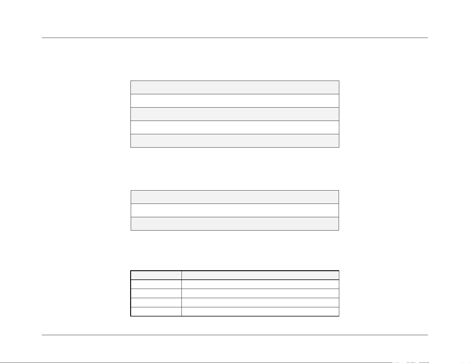
The following table lists the components that have been approved for use with the iR1600 modem:
Part Number Product Name
5000-C5-RFM Cellular Antenna Magnetic Mount (Motorola)
5010-C5-RFM Cellular Antenna Magnetic Mount (spring wire)
5020-C5-RFM Cellular Antenna Direct Mount (soft rubber)
nextel.com
Antennas
7
Page 13
Installation Guide
5030-C5-RFM GPS Antenna Magnetic Mount (Lassen LP)
5040-C5-RFM Cellular Antenna Fixed Mount
5050-C5-RFM Dual Cellular/GPS Antenna Fixed Mount
5060-C5-RFM Dual Cellular/GPS Antenna Covert
5070-C5-RFM Cellular Antenna Glass Mount
5080-C5-RFM Dual Cellular/GPS Antenna Glass Mount
5085-C5-RFM Dual Cellular/GPS Antenna Fixed Mount Radome
5090-C5-RFM Dual Cellular/GPS Antenna Magnetic Mount
Power Harnesses and Adapters
5110-C5-RFM Vehicle Power Harness for iR1600
5260-C5-RFM AC Power Adapter Kit for iR1600
5290-C5-RFM AC Power Adapter Kit for iR1600 (Extended temperature)
Optional Hardware Components
5220-C5-RFM Ignition Bypass Plug
5230-C5-RFM Coaxial Antenna Adapter, Mini UHF Male/TNC Female
5240-C5-RFM USB to Serial Adapter
5400-C5-RFM 2M DB9M to DB9F Serial Cable
5410-C5-RFM 3M DB9M to DB9F Serial Cable
5300-C5-RFM Solar Panel Kit (sizing required)
IMPORTANT: eLutions updates the list of approved components as
!
needed to accommodate the variety of installation environments and
industry solutions. Please check eLutions’ web site for an up to date
components list.
8
nextel.com
Page 14
Required Components for Operation
In order for you to begin using your modem and connect to the iDEN network, you must have the following components:
• iDEN
• Activated Data Account with Nextel
Packet Data Applet
Installation Guide
!
IMPORTANT: Before you can begin using the iR1600 Rugged
Modem or the iR1600 GPS-Enabled Modem in normal mode, you
must have an activated data account with Nextel.
iDEN
Packet Data Applet
The iDEN Packet Data Applet must be downloaded and successfully installed on the computer (laptop/MDT) that the modem is connected to.
Please refer to the “Installing iDEN
Packet Data Applet” section of the Configuration Guide for detailed instructions on how to install and
configure the data applet.
NOTE: This component is only required if the modem is operating in Normal Mode. Packet data service is required if the modem is operating in Gateway or AVL mode.
Please refer to the “Modem Operating Mode” topic located on page 15 for a description of the operating modes.
Data Account Activation
For information on how to obtain a data account, please contact your technology administrator or designated field care representative.
nextel.com
9
Page 15

Installation Guide
This page intentionally left blank.
10
nextel.com
Page 16

INTRODUCTION
Installation Guide
Thank you for purchasing the Nextel® iR1600 modem. Once installed and configured, the iR1600 modem provides you with reliable, wireless
data communication within the iDEN
Nextel
For details on Nextel digital cellular and data coverage, visit nextel.com.
Nextel
For network issues contact:
For installation or device issues contact:
Coverage
Customer Care
• Nextel Customer Care Center at 1-800-639-1111
• eLutions Wireless Support Center by phone at 1-888-349-4338 or by email at [email protected]
network. This chapter includes:
Nextel Coverage
Nextel Customer Care
Page 11
Page 11
To Order Components
Components for the iR1600 modem can be ordered online at www.elutions.com/wireless or by calling eLutions’ Wireless Support Center.
When you call, please have a detailed description of your problem. To provide you with fast and quality support, our Customer Care
representative may ask for the following:
• Computer operating system (Windows 95/98/NT/2000/CE)
• Version of the operating system (e.g. NT 4, Windows 95 Version B, CE 2.1, etc.)
• Information regarding the modem (most can found on the diagnostic menu)
• Geographic location of use
• The modem’s operating mode
• Other configuration settings
nextel.com
11
Page 17

Installation Guide
This page intentionally left blank.
12
nextel.com
Page 18
Installation Guide
PRODUCT OVERVIEW
This chapter contains general product information for the iR1600 modem. This chapter includes:
General Overview Page 13
Modem Characteristics Page 14
Modem Operating Modes Page 15
Data Connections Page 15
Modem Types
Modem Components
Modem Technical Specifications Page 18
General Overview
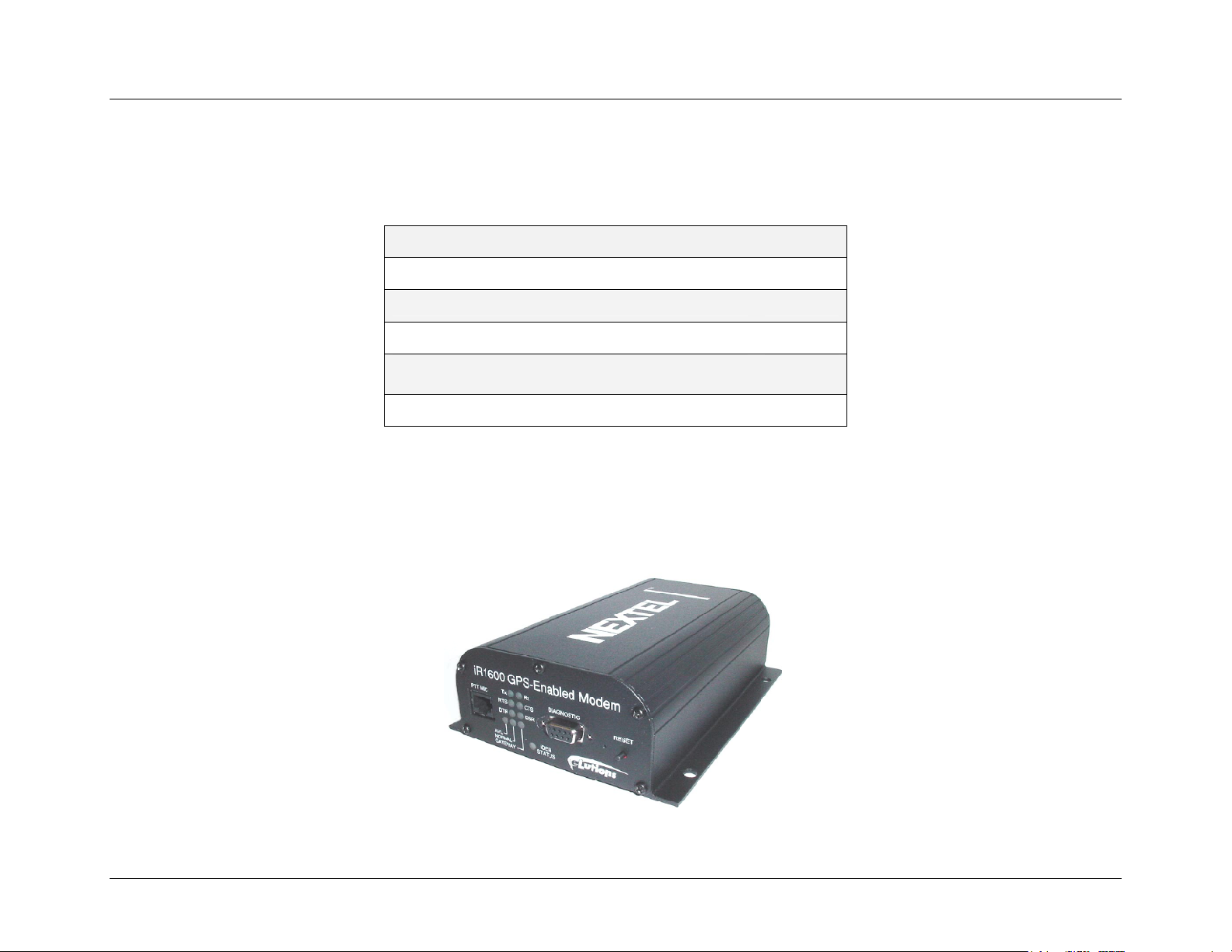
The iR1600 modem includes capabilities such as embedded TCP/IP stack, alternate serial protocol conversion, store-and-forward for GPS
coordinates and three (3) operating modes (Normal, AVL or Gateway). The expanded features make the iR1600 even more powerful while
still maintaining the same ruggedized, flexible and reliable form factor.
Page 15
Page 16
Figure 1 – iR1600 GPS-Enabled Modem
nextel.com
13
Page 19

Installation Guide
Modem Characteristics
The iR1600 modem provides you with the following features/ characteristics:
• Integrated GPS Receiver (optional) – The iR1600 has an integrated receiver for GPS communication for Automatic Vehicle Location
(AVL). With GPS, vehicle location or “positions” can be determined. GPS data is used with mapping software so that vehicle location and
movement can be visually represented.
• Store and Forward Capabilities – The iR1600 has a total of 120kbytes of serial flash memory for data storage, giving the iR1600 data
logging and store/forward capabilities. If a unit loses communication, the data being collected through GPS and from the inputs will be
stored in memory and forwarded when communication is reestablished.
• I/O Interfaces – The iR1600 has five (5) I/O ports: (2) Analog inputs (4-20mA/0-10V configurable) and (3) digital inputs. These signals
provide a means of monitoring and controlling third party devices that are external to the modem.
• TPC/IP Stack – The TCP/IP Stack allows the iR1600 to receive serial data, encapsulate it into UDP or TCP packets and send it over the
iDEN
iDEN
packet data network to a pre-defined IP address. This also allows the modem to receive appropriately addressed packets from the
network, parse the data, and send it to the user via the serial port.
• Internal GPS Loop Back – The addition of the TCP/IP Stack has enabled the iR1600 with the capability of sending GPS data to a remote
server without a resident application. The GPS data is also communicated via a serial connection to a local data terminal.
• Data Security – The modem provides a 128-bit AES (Advanced Encryption Standard) data security feature when the modem is operating in
either the Gateway or AVL mode.
• Remote Over the Air (OTA) Configuration Toolkit (optional) – The iR1600 modem can be remotely configured by using this toolkit.
This optional toolkit is a GUI (Graphic User Interface) application allows an administrator the ability to remotely configure or change the
modem’s operating modes or perform remote firmware updates. This feature is enabled when the modem is operating in either the Gateway
or AVL mode.
• Access Control List (ACL) – The modem has a look-up table that can store a range of IP addresses and up to 30 individual IP addresses
within the Access Control List. When the modem is in either Gateway or AVL operating mode and configured as a TCP client or UDP, it
will act as a “listener” and will use the ACL to verify that a remote node may send packets to the modem.
• Protocol to IP Address Translation – The iR1600 has capabilities of translating a Bristol Babcock BSAP hex address (ID) into an IP
address. Once converted, the BSAP messages (data) is packetized and sent over the iDEN
network using UDP.
14
nextel.com
Page 20

Installation Guide
Modem Operating Modes
The iR1600 provides three separate modes of operation or communication described below.
NOTE: The iR1600 is configured to default to the Normal mode. You can switch to a different mode by changing parameters through the modem’s diagnostic
• AVL: In this mode, the modem uses the internal GPS receiver to send GPS NMEA sentences over the packet data network to a specific IP
address and port number. The data is encapsulated into UDP or TCP packets, which allows it to be transmitted over the iDEN
network to a pre-defined IP address. The modem maintains a non-volatile revolving history of the GPS information and provides a ‘store
and forward’ capability for periods when communication within the iDEN
the modem is also active.
NOTE: Only the iR1600 GPS-Enabled modem can operate in the AVL mode and send AVL messages.
• GATEWAY: In this mode, the modem receives basic serial data from the host device via the user port, and encapsulates it into UDP or
TCP packets. The data is sent out over the iDEN
appropriately addressed packets from the iDEN
• NORMAL: In this mode, an IP enabled host device may utilize the iDEN
Alternately, a non-IP enabled host may make an iDEN
menu. Please refer to the “Configuring for Gateway/AVL Mode” chapter in the Configuration Guide for detailed instructions on how to switch operating
modes.
packet data
network is lost. When AVL mode is activated, the GPS port on
packet data network to a pre-defined IP address. Similarly, the modem receives
network, parses the data, and sends it to the user via the serial port.
circuit switched connection using standard Hayes AT commands.
packet data network via a PPP connection to the iR1600 modem.
Data Connections
The iR1600 provides the following data connections:
• Packet Data: A wireless modem connection used for accessing the Internet, sending and receiving e-mail, and transferring small files over
the packet data network using standard IP protocols. Data is sent in packets (blocks) of data at high speed.
• Circuit Switched Data: A wireless modem connection for sending and receiving data (faxes, files, etc.) over the circuit-switched cellular
channel, providing a direct point-to-point connection with the destination device.
Modem Types
Nextel offers two models of the iR1600 Modem. Both are designed to provide wireless communication for rugged environments. The distinction
between the two models is the optional GPS feature. The iR1600 modem is available in the following models:
• iR1600 Rugged Modem (Base Model) - Available in bulk or individual packaging.
• iR1600 GPS-Enabled Modem - Available in bulk or individual packaging.
nextel.com
15
Page 21
Installation Guide
Modem Components
Front Panel Views
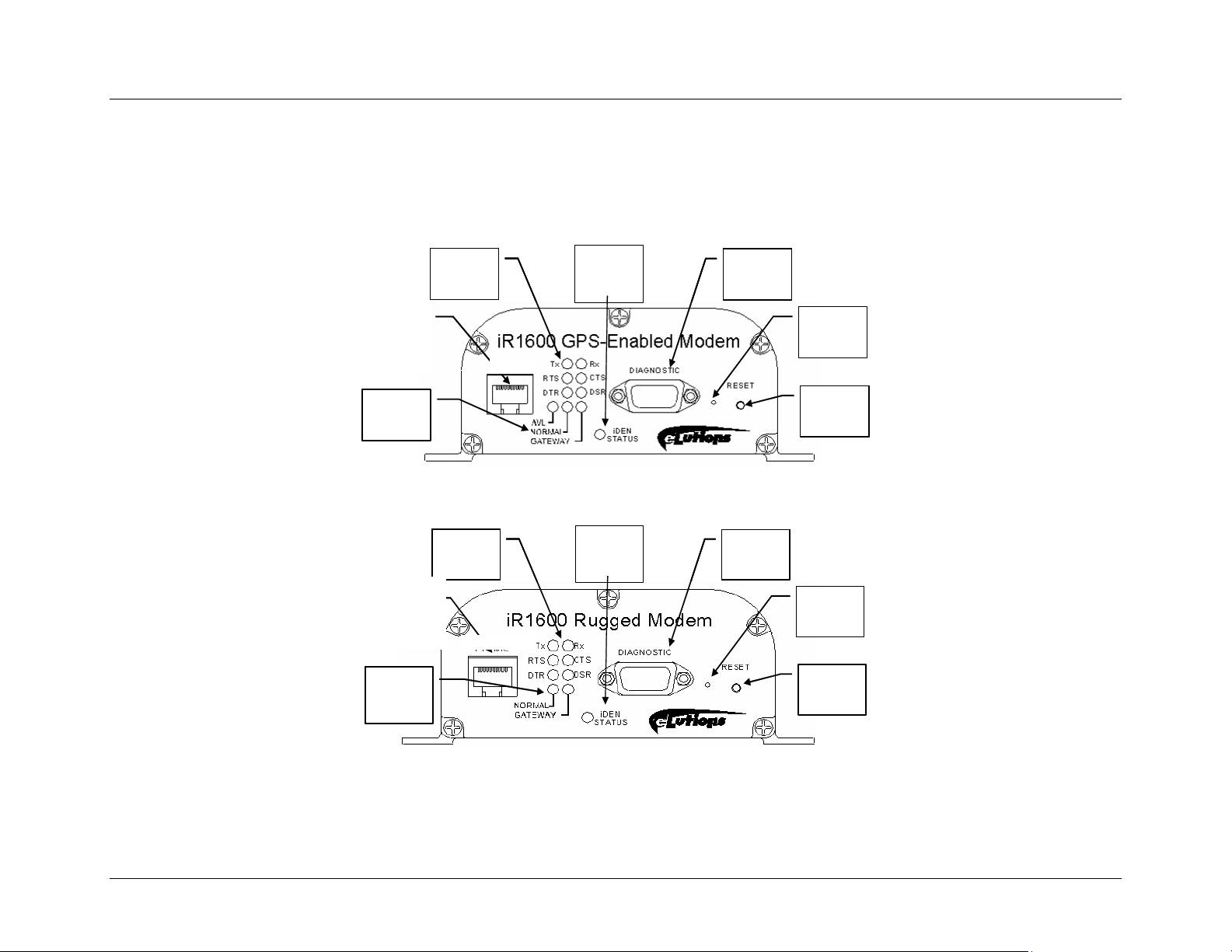
The following diagrams display the components that exist on the front panel for both the iR1600 GPS-Enabled and iR1600 Rugged Modems.
iDEN
iDEN
Netwo rk
Netwo rk
Stat us
Stat us
Indicator
Indicator
Diagnostic
Diagnostic
Port
Port
Master
Master
Reset
Reset
Button
Button
Soft
Soft
Reset
Reset
Butt on
Butt on
Microphon e/
Microphon e/
Speaker
Speaker
Connector
Connector
Modem
Modem
Opera ting
Opera ting
Indicators
Indicators
PTT
PTT
Mode
Mode
RS-23 2
RS-23 2
Status
Status
Indicators
Indicators
16
Microphone/
Microphone/
Conne cto r
Conne cto r
Oper ati ng
Oper ati ng
Indic ators
Indic ators
PTT
PTT
Speaker
Speaker
Modem
Modem
Mode
Mode
Figure 2 – Front Panel of iR1600 GPS-Enabled Modem
iDEN
RS-2 32
RS-2 32
Status
Status
Indicat ors
Indicat ors
iDEN
Networ k
Networ k
Status
Status
Indicator
Indicator
Diagnost ic
Diagnost ic
Port
Port
Figure 3 – Front Panel of iR1600 Rugged Modem
nextel.com
Master
Master
Reset
Reset
Button
Button
Soft
Soft
Reset
Reset
Button
Button
Page 22
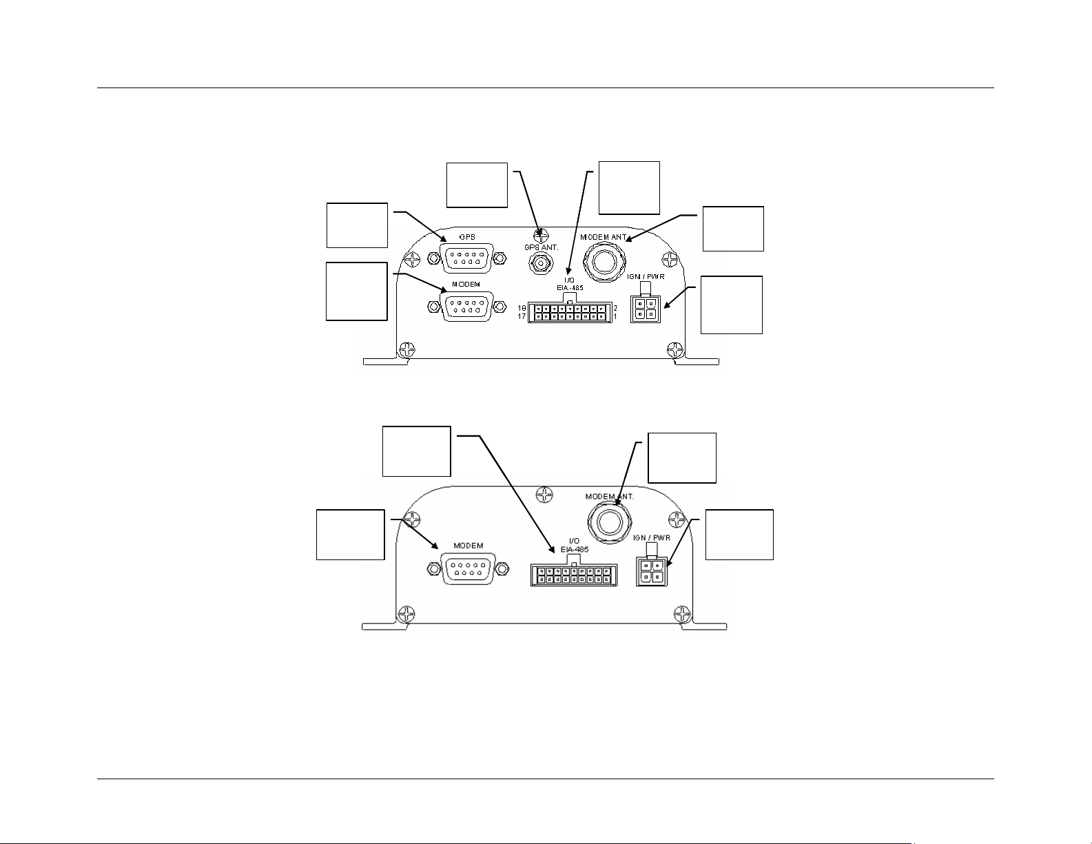
Installation Guide
Rear Panel Views
The following diagrams show the components that exist on the rear panel of the iR1600 GPS-Enabled and iR1600 Rugged Modems.
Input/
Input/
Outp ut
Outp ut
Interf ace
Interf ace
Connector s
Connector s
Modem
Modem
Ant enna
Ant enna
Connector
Connector
Ignition
Ignition
Sense and
Sense and
Power
Power
Connector
Connector
GPS Data -
GPS Data -
Seri al
Seri al
Connector
Connector
Modem
Modem
Data -
Data -
Seri al
Seri al
Connector
Connector
GPS
GPS
Ant enna
Ant enna
Connector
Connector
Figure 4 – Rear Panel of iR1600 GPS-Enabled Modem
Input/
Input/
Output
Modem
Modem
Data -
Data Serial
Serial
Connector
Connector
Output
Interface
Interface
Connectors
Connectors
Figure 5 – Rear Panel of iR1600 Rugged Modem
Modem
Modem
Antenna
Antenna
Connector
Connector
Ignition
Ignition
Sense and
Sense and
Power
Power
Connector
Connector
nextel.com
17
Page 23
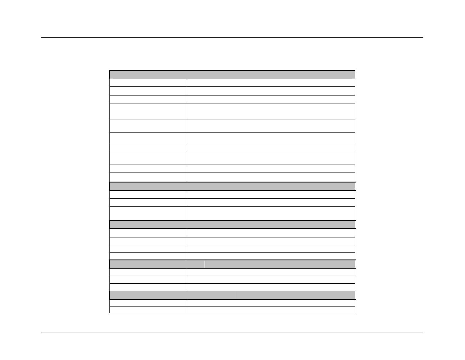
Installation Guide
Modem Technical Specifications
The following section outlines the technical specifications of the iR1600 modems.
Product Characteristics
Modem Data Interface
Diagnostics Data Interface
Optional GPS Interface
Input/Output Interfaces
External Input/Output
Connector
Power/Ignition Sense Input
Connectors
Antenna Interface
LED indicators
Reset Button
Master Reset Button
Operational Characteristics
Data Security
Protocol Conversion
Over the Air (OTA) Remote
Configuration
Processors
Program Flash
Data Logging and Storage
Real Time Clock
TCP/IP Stack
Physical Characteristics
Weight
Dimension
Case
Electrical Characteristics
Power Input
Input Current – OFF Mode
RS-232 port utilizing a DB9 female pin serial connector
RS-232 port utilizing a DB9 female pin serial connector
RS-232 port utilizing a DB9 female pin serial connector
5 external I/O signals: 2 analog inputs (0-10Vdc or 4-20mA current
input), 3 digital inputs (+12V/Open or Open/Grnd)
18 Pin external I/O connector
4 Pin Molex power/ignition connector combined
Mini UHF female for modem and MCX female for GPS
6 SIGNAL and 3 OPERATING MODE and 1 bi-color STATUS
indicators
YES
YES (recessed)
128-bit AES
YES, BSAP
YES
128k bytes of program flash
120k bytes of data flash
YES
YES
625 grams
5.04"Wx2.25"Hx7"D
Dust and water resistant, black aluminum extrusion
13 VDC ± 40%
70 uA steady state to 2.5 mA transient peak
18
nextel.com
Page 24
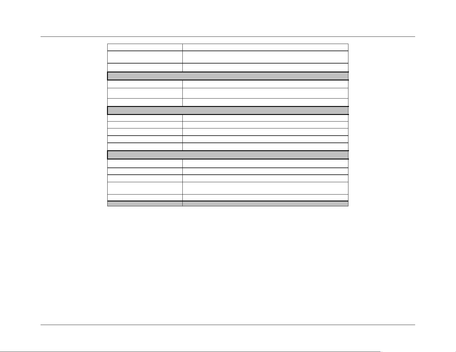
Installation Guide
Input Current - ON Mode
Input Current - SLEEP
Mode
Tx Output
Communication
Communication Networks
Operating Modes
Radio Frequency
GPS Characteristics
GPS Receiver
GPS Data Protocols
GPS Engines
GPS Messages
Update Rate
Environmental Parameters
Operating Temperature
Storage Temperature
Operating Humidity
Shock & Vibration
Conformance
EMI/EMC
100 mA steady state to 1.5A transient peak
40 mA max
600 mW Typical
iDEN
3 Operating Mode options: MODEM, AVL and GATEWAY.
Tx 806-825 MHz Rx 851-870 MHz
8 channel with 32 correlators
NMEA 0183 v3.0, optional TSIP and TAIP
Trimble
GGA, VTG, GLL, RMC, ZDA, GSA, GSV
Up to 1 Hz
-25°C to +60°C
-40°C to +85°C
0-95% non-condensing @ +50°C
Per MIL-STD-810E
FCC Part 15, Part 90
nextel.com
19
Page 25

Installation Guide
This page intentionally left blank.
20
nextel.com
Page 26

INSTALLATION PREPARATION
In this chapter, you will learn how to begin installing your iR1600 modem. This chapter includes:
Before You Start Installing Page 21
Installation Guide
Installation Planning
Planning Modem Location
Modem Dimensions
Planning Antenna Location
Planning Cable Layout
Serial Cable Routing
Installation Tools Page 25
Page 21
Page 22
Page 23
Page 24
Page 25
Page 25
Before You Start Installing
Only experienced technicians familiar with installing similar types of hardware equipment should install the modem. For safety and to avoid
damage to the modem or vehicle wiring, the installer should have knowledge of the following subjects.
• Antenna location
• Automotive wiring (if applicable)
• Vehicle cable routing (if applicable)
• Configuration tools (i.e. serial cable, data terminal with HyperTerminal software)
Installation Planning
Planning is the key to a quick and simple installation. Before drilling holes or running wires, you should inspect the vehicle or area of the building
to determine how and where you intend to mount the modem, antenna and components.
nextel.com
21
Page 27
Installation Guide
Planning Modem Location
Factors to consider when planning for the location or placement of your iR1600 modem:
• Easily Accessible – You should allow easy access to the modem (for troubleshooting purposes).
• Easily Visible – You should allow a clear view of the modem’s LED indicators.
• Proximity of the Cables – The distance between connections, especially that between the modem and antenna, affects performance. The
shorter the distance between these components, the better the signal. (Please refer to the antenna’s Safety Warranty for proper installation
of the antenna.)
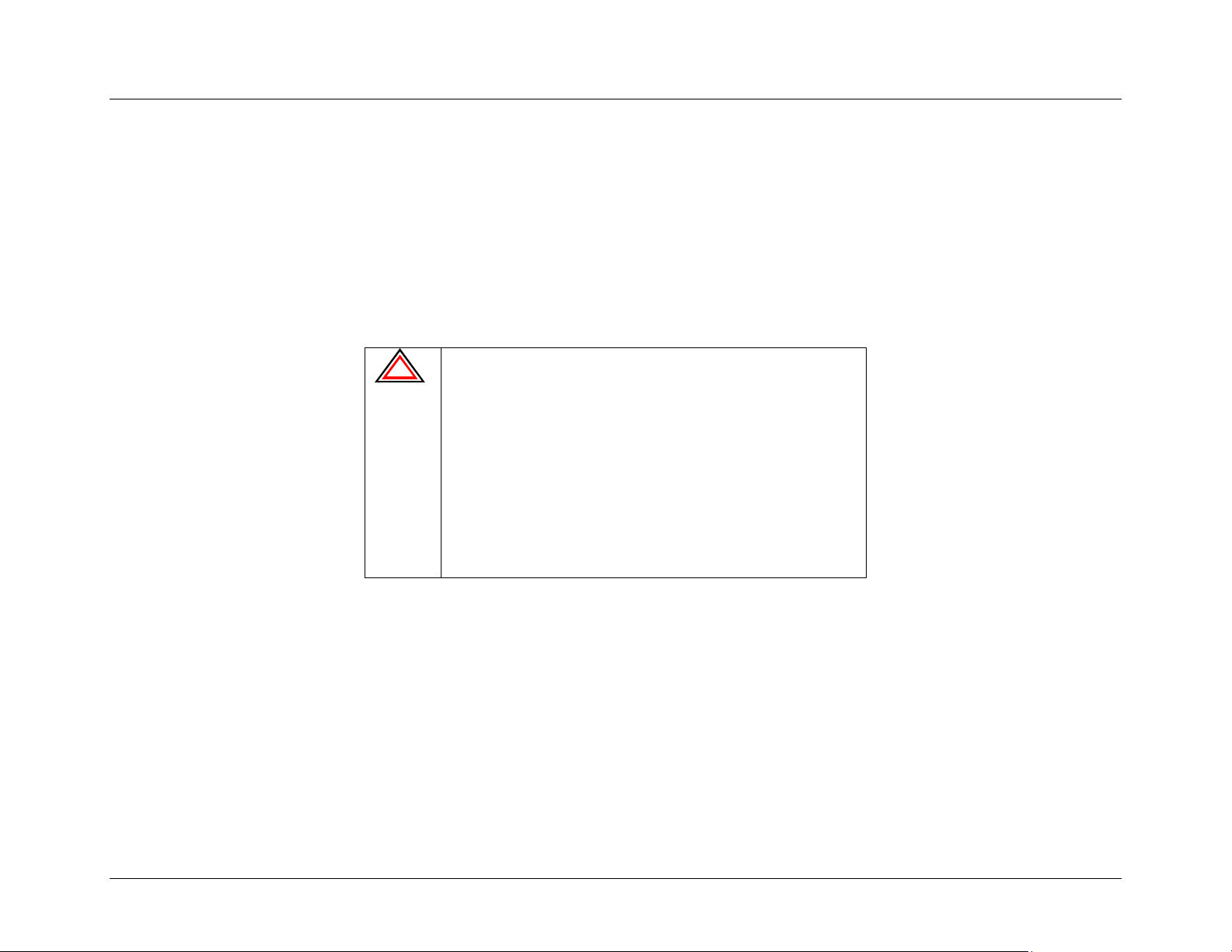
• Environment Considerations:
!
Heat - Placing the modem, antenna or cables near a
heat source can cause several problems, including
radio interference. Select a location away from a
source of heat and make sure the modem has at least
a 1-inch clearance on all sides for cool air to
circulate.
Wetness – The modem should not be mounted in an
area where it could be directly exposed to water.
Direct Sunlight – The modem should not be
mounted in direct sunlight.
22
nextel.com
Page 28
Installation Guide
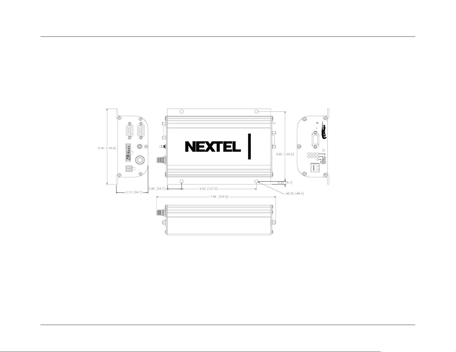
Modem Dimensions
Consider the size of the modem. Will the modem fit in the area where you want to perform the installation?
The following diagram outlines the modem’s dimensions:
NOTE: This diagram depicts the overall view of the iR1600 Rugged and iR1600 GPS-Enabled Modems. This diagram is not intended to be used as a template for
mounting the modem. Please refer to the Table of Dimensions located on page 24 for the modem’s approximate dimensions.
MODEM
GPS
TM
18
GPS ANT.
EIA-485
I/O
MODEM ANT.
2
117
IGN / PWR
Figure 6 – Overall view of iR1600 GPS-Enabled Modem
RxTx
iR1600 GPS-Enabled Modem
RESET
DIAGNOSTIC
iDEN
STATUS
DSR
CTS
RTS
DTR
PTT MIC
nextel.com
23
Page 29
Installation Guide
Table of Dimensions
The following table describes the overall dimensions of the iR1600 modem.
Component Dimension
Overall dimensions from connector to
connector
7.96in. [202.2mm]
End panel to end panel 7.09in. [180.14mm]
Width (including mounting tabs) 5.30in. [134.62mm]
Width of enclosure 4.30in. [109.22mm]
Height of enclosure 2.13in. [54.10mm]
Planning Antenna Location
Factors to consider when planning for the location or placement of the antenna:
• Choose a location with easy access to cable routing to ease the process of connecting the antenna to the modem.
• In mobile installation, mount the modem antenna on the center of the outside trunk for optimum signal reception.
• If you are installing the iR1600 GPS-Enabled Modem in a fixed (building or desk) environment, ensure that the GPS antenna is positioned
where it has a direct line-of-sight to the sky. In some cases, this can be accomplished by placing the antenna adjacent to a window. In most
cases it will require mounting outside of the building.
24
The cellular antenna(s) used for this transmitter must not be co-located
or operated in conjunction with any other antenna or transmitter. This
device is approved with emissions having a source-based timeaveraging duty factor not exceeding 67.5%.
Vehicle – Antenna Installation:
• Antennas used for this transmitter must not exceed an antenna gain of 5
dBd (commonly specified as 3dB gain).
• For rear deck trunk and rooftop installations, the antenna must be
located at least 20 cm away from rear-seat passengers and bystanders
in order to comply with the FCC RF exposure requirements.
IMPORTANT: Failure to observe these restrictions will result in exceeding the FCC RF
exposure limits.
nextel.com
Page 30

Installation Guide
Planning Cable Layout
Once you have chosen the location of the modem and antenna, and before installing, layout the cables to determine:
• If the cables can reach the modem and antenna.
• If the distance between components is adequate and allows you to make adjustments to receive a better signal. (Please refer to the
manufacturer’s installation manual for safe installation of your antenna).
• If there are kinks or bends in the cable or obstructions in the vehicle that could affect routing.
Serial Cable Routing
Serial cable routing is the most important factor to ensure a trouble-free operation. The serial cable should be as stable as possible (e.g., it should
experience little to no movement and have few or no bends or kinks).
NOTE: The majority of problems occur because of serial cable failure.
Installation Tools
You will need these tools to install the iR1600 modem.
• Portable Drill • Phillips Screwdriver • Connector Crimp tool
• Center Punch • Hammer • Four #10 self-tapping sheet metal screws
nextel.com
25
Page 31

Installation Guide
This page intentionally left blank.
26
nextel.com
Page 32

Installation Guide
MOBILE INSTALLATION
This chapter includes instructions on how to install your iR1600 modem and hardware components (i.e. antennas, serial cables, etc.) within a
mobile environment.
Installation Steps Page 27
Mounting the Modem
Select Modem Location
Mount the Modem
Mounting the Antenna(s)
Approved Antennas
Select Antenna Location
Mount the Modem Antenna
Mount the GPS Antenna (optional)
Route and Connect Cables
Approved Power Cable
Route and Connect Power/Ignition Cable
Route and Connect Antenna Cable(s)
Route and Connect Data Cable(s)
Other Installation Configurations
Continuous Power Configuration
Docking Station Configuration
Page 28
Page 28
Page 28
Page 29
Page 29
Page 29
Page 30
Page 30
Page 31
Page 32
Page 33
Page 33
Page 33
Page 34
Page 34
Page 37
Installation Steps
To install, you must perform the following steps:
• Mount Modem – Mount the modem in the desired location.
• Mount Antenna – Mount the antenna using the instructions included with your selected antenna’s installation guide.
• Route and Connect Ignition/Power – route the power cable from modem to the vehicle’s power supply (ignition switch).
• Connect Antenna Cable – Connect the cable to the mounted modem and antenna.
• Connect Data Cable – Connect the data cable from the modem to the mobile device.
nextel.com
27
Page 33
Installation Guide
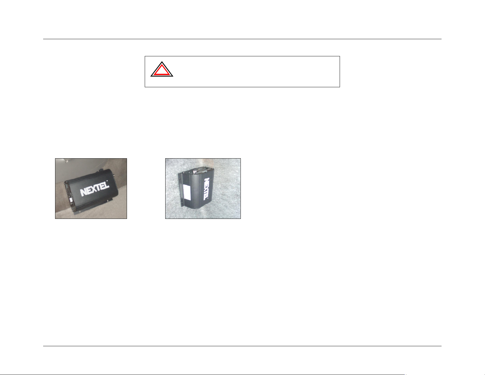
IMPORTANT: We recommend that the modem be configured prior to
!
mobile/vehicle installation. This process requires that you have
knowledge of TCP/IP communication and modem operation. Please
refer to the iR1600 Configuration Guide for detailed instructions on
how to configure the iR1600 modem.
Mounting the Modem
Select Modem Location
The following describes typical locations that you should consider for mounting the modem:
• Under seat • Inside dashboard
• Under dashboard • Center console
• In trunk • In accessory compartment
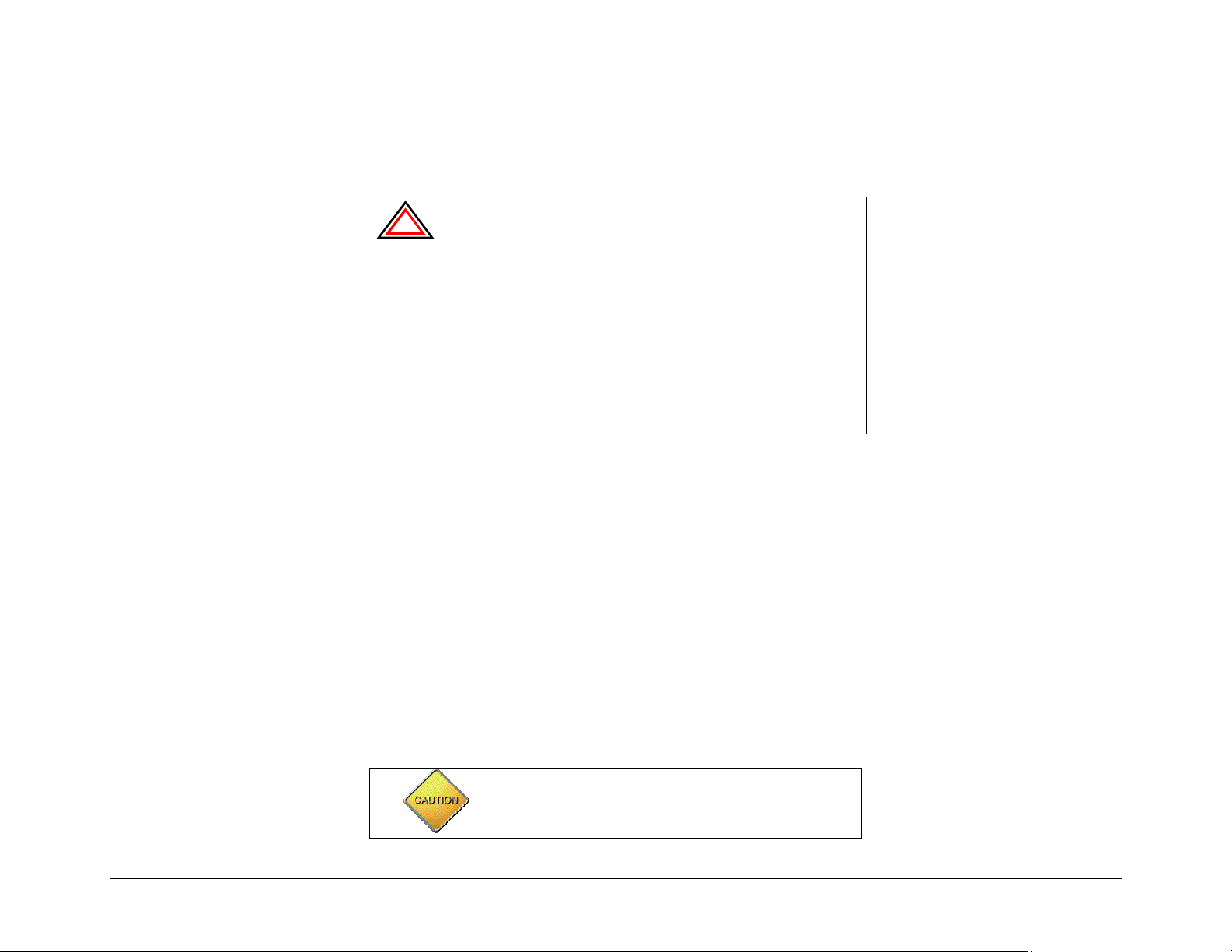
Example of iR1600 mounted on
side of console
Example of iR1600 mounted on
side wall of trunk
Mount the Modem
The following steps describe how to mount the iR1600 data modem in a mobile environment.
1. Determine a convenient location in the mobile environment.
2. Use the iR1600 modem and mark the positions of the holes on the mounting surface.
3. Drill the holes in the marked location.
4. Mount the unit using the #10 sheet metal screws.
28
nextel.com
Page 34
Installation Guide
Mounting the Antenna(s)
The location of the antenna should be chosen carefully.
IMPORTANT: Things to consider when installing the antenna
!
Approved Antennas (sold separately)
For a list of tested and approved antennas that can be used with the iR1600 modems, please refer to the Approved Components List on page 7 of
this document.
NOTE: Antennas with gain exceeding 5dBd (commonly specified as 3dB gain) do not comply with FCC RF exposure and are not allowed for use with this product.
equipment.
• Equipment must be installed in accordance with the manufacturer’s
instructions
• To ensure compliance with United States FCC regulations on RF
exposure, equipment must be installed in such a way as to
maintain a separation of at least 8 inches (20 cms) between the
antenna and the human body.
• Ensure that the antenna is properly installed external to the mobile
environment and in accordance with the requirements of the
antenna manufacturer/supplier.
• Use only an approved antenna. Unauthorized antennas,
modifications or attachments could impair call quality, damage the
modem, or violate FCC mandates.
Select Antenna Location
The following are some common layouts for co-locating an external antenna and the iR1600 modem.
• Roof to trunk – This layout accommodates a trunk-mounted modem and antenna that is attached to the roof.
• Trunk to trunk – This layout accommodates a trunk-mounted modem and antenna that is attached to the trunk.
• Roof to console or dashboard – This layout accommodates a console or dashboard mounted modem and the antenna attached to the roof.
This setup gives you access to the modem from inside the vehicle.
The cellular antenna(s) used for this transmitter must not
be co-located or operated in conjunction with any other
antenna or transmitter. This device is approved with
emissions having a source-based time-averaging duty
nextel.com
29
Page 35

Installation Guide
factor not exceeding 67.5%.
Vehicle – Antenna Installation:
• Antennas used for this transmitter must not exceed an
antenna of 5 dBd (commonly specified as 3dB gain).
• For rear deck trunk and rooftop installations, the antenna
must be located at least 20 cm away from rear-seat
passengers and bystanders in order to comply with the
FCC RF exposure requirements.
IMPORTANT: Failure to observe these restrictions will result in exceeding the
FCC RF exposure limits.
Mount the Antenna(s)
NOTE: Each antenna has specific installation instructions. Please refer to the antenna installation instructions for specific requirements and details.
Mount Modem Antenna
The following steps describe how to mount a modem antenna.
1. Use an antenna suitable for the cellular band of frequencies (806-870 MHz) with Mini UHF
jack and matched for 50-ohm impedance.
2. Mount the antenna according to the manufacturer’s specifications or instructions.
Mount GPS Antenna (optional)
The iR1600 GPS-Enabled modem comes equipped with a connector for a GPS antenna. The following steps describe how to mount a GPS
antenna.
1. Use an antenna suitable for the GPS of frequency 1575 MHz with an MCX connector and
matched for 50-ohm impedance.
2. Position the antenna where it has a direct line-of-sight to the satellite.
3. Mount the antenna according to the manufacturer’s specifications or instructions.
NOTE: Because of the operating frequencies involved with the GPS signal, splicing or using adapters to extend the length of the antenna coaxial
30
cable is not recommended and will likely prevent the system from operating properly. We recommend that a single length of coax without
splices or adapters be used.
nextel.com
Page 36
Route and Connect Cables
Approved Power Cable (sold separately)
The following DC power cable was designed specifically for use with the iR1600.
5110-C5-RFM – Vehicle Power Harness (iR1600)
Installation Guide
!
with the iR1600 modem. Use of unapproved components violates the
modem’s warranty.
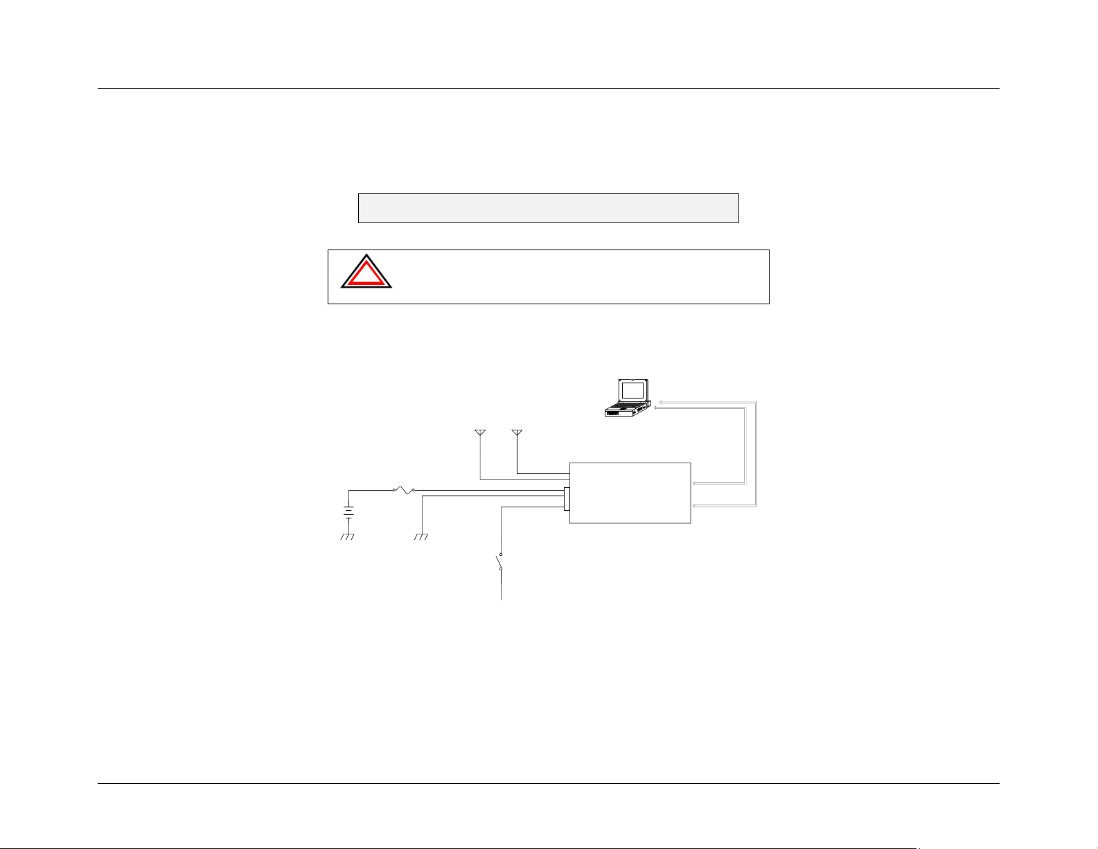
The following diagram illustrates typical installation wiring of the iR1600 into a mobile environment.
MOBILE DATA
COMPUTE R
IMPORTANT: Only approved and tested components should be used
FUSE
+12VDC
VEHICLE BATTERY
GPS ANTE NNA
(OPTIONA L)
Figure 7 – iR1600 Installation Wiring Diagram (Mobile)
ENGINE IGNITION
SWITCH
+12VDC
MODEM
ANTENNA
POWER /
IGNITION
iR1 600
RS-232
GPS DATA
RS-232
MODEM DA TA
nextel.com
31
Page 37
Installation Guide
Route and Connect Ignition/Power
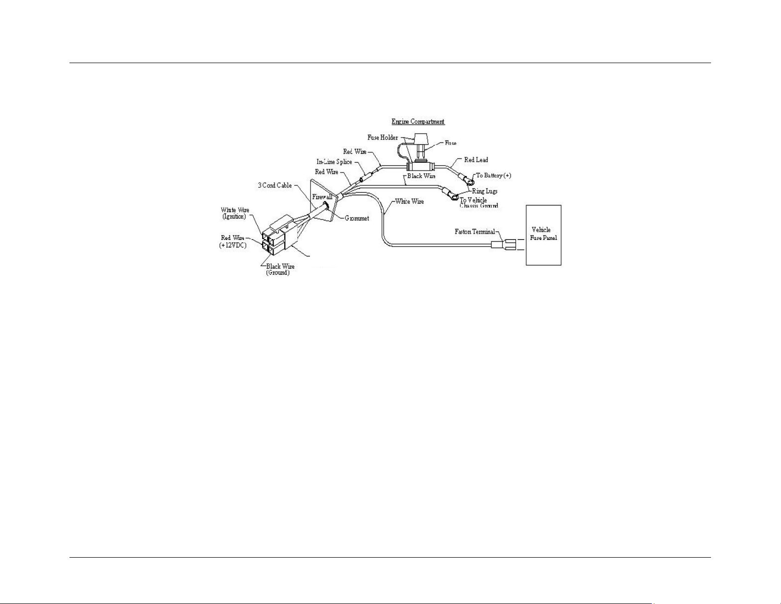
Route the ignition/power cable using the following diagram as a guideline:
To iR1600
Connector
Figure 8 – Modem Power Wiring Diagram
The following steps describe how to route and connect the power cable:
1. Determine a cable routing plan that will allow you to connect the DC power cable between the modem and the vehicle
battery. Connect the male end of the power cable to the 4-prong connector labeled IGN/PWR on the rear panel of the
modem.
2. Route the free end of the cable to the vehicle battery. If necessary, drill a hole in the vehicle firewall and route the cable
through it using the supplied grommet. (Refer to Figure 8 on page 32).
3. Locate an available chassis ground mounting point near the battery and shorten the black lead to remove any excess
cable length.
4. Crimp on the ring tongue terminal and connect the black lead directly to the chassis ground.
5. Position the fuse holder as close to the battery as possible, and away from any potentially hot components.
6. Mount the fuse holder by tie wrapping it to the other cabling wires and dress wires as necessary.
32
nextel.com
Page 38
Installation Guide
7. Shorten the red lead of the DC power cable to remove any excess length and crimp the fuse holder’s red lead to it using
the in-line splice.
8. Connect the ring tongue terminal from the fuse holder to the positive (+) battery terminal.
9. Connect the free end of the ignition wire to a vehicle circuit that provides 12VDC when the vehicle is running or in
ACC, and no 12VDC when the vehicle is OFF or not in ACC.
Route and Connect Antenna Cable(s)
The following steps describe how to connect the antenna cable(s) to the modem:
1. Insert the male end of the modem antenna cable to the connector labeled MODEM ANT
on the rear panel of the modem.
2. Insert the male end of the GPS antenna (optional) cable to the connector labeled GPS ANT
on the rear panel of the modem.
Route and Connect Data Cable(s) – sold separately
The iR1600 modem can be connected to the host DTE equipment using standard “straight through” 9-pin male to a 9-pin female serial cable(s).
Serial Connector (DB9) Pinouts
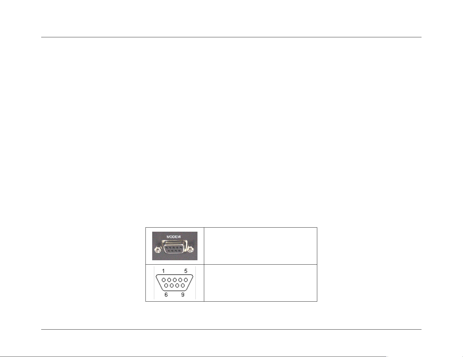
The following diagrams and table outlines the iR1600 RS232 pin assignments.
1. Data Carrier Detect (DCD)
2. Transmitted Data (TXD)
3. Received Data (RXD)
4. Data Terminal Equipment Ready (DTR)
5. Signal Ground (GND)
6. Data Communications Equipment Ready (DSR)
7. Request to Send (RTS)
8. Clear to Send (CTS)
9. Ring Indicator (RI)
nextel.com
33
Page 39
Installation Guide
The following step describes how to connect the data cable:
1. Connect the 9-pin male end of the cable to the iR1600 MODEM communication connector, located on the rear panel of
the modem and the 9 pin female end of the cable to the data terminal equipment (DTE).
2. Connect the 9-pin male end of the cable to the iR1600 GPS communication connector, located on the rear panel of the
modem and the 9 pin female end of the cable to the data terminal equipment (DTE).
Other Mobile Installation Configurations
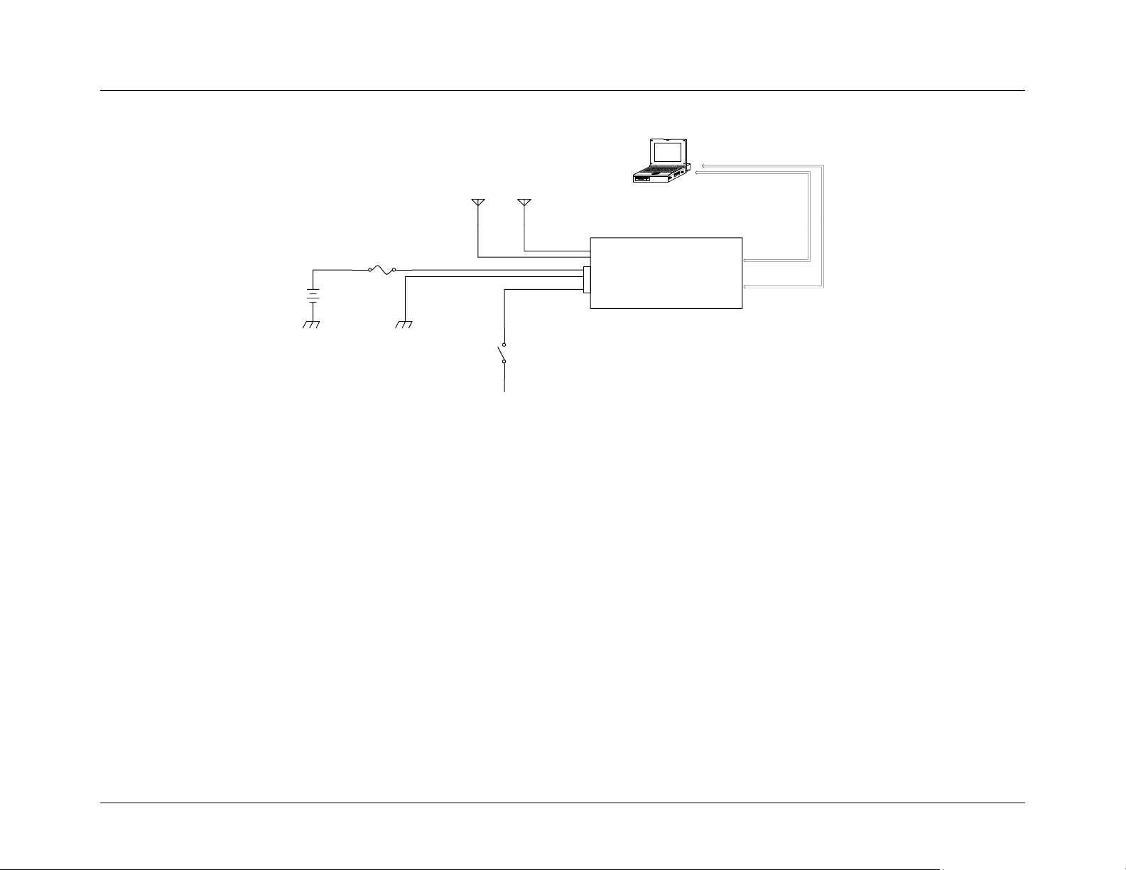
Continuous Power Configuration
There is no on/off switch on the iR1600. It is turned on and off through the application of voltage to the ignition sense input, typically supplied
by the vehicle’s ignition switch. The Continuous Power Configuration allows the iR1600 to remain ON even when the vehicle ignition is off.
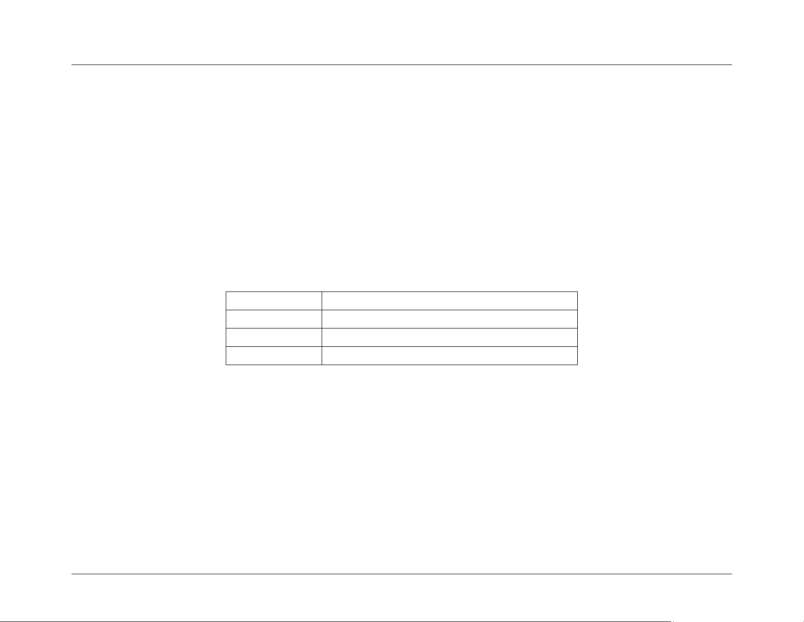
NOTE: You will need to purchase a SPST toggle switch. Please refer to the following table for the specifications of the required toggle switch for this
configuration.
34
Switch Feature:
Switch Function:
Switch Circuit:
Current Rating:
12 VDC SPST Toggle Switch
SPST (Single Pole, Single Throw)
On-Off
Minimum of 20Vdc at a current of 5mA.
nextel.com
Page 40
Installation Guide
MOBILE DATA
COMPUTER
+12VDC
VEHICLE
BATTERY
FUSE
GPS ANTENNA
(OP TION AL )
+12VDC
ALWAYS ON
MODEM
ANTENNA
DASHBOARD MOUNTED
TOGG LE S WITCH
POWER /
IGNITION
Figure 9 – Continuous Power Configuration
Mounting the Modem
Mount the modem as described for the standard mobile installation on page 28.
Mounting the Antenna(s)
Mount the antenna(s) as described for the standard mobile installation on page 30.
Route and Connect Ignition/Power
Route and connect the ignition/power cable as described in the following steps.
1. Determine a cable routing plan that will allow you to connect the DC power cable between the modem and the
vehicle battery. Connect the male end of the power cable to the 4-prong connector labeled IGN/PWR on the rear
panel of the modem.
iR1600
RS-232
GPS DATA
RS-232
MODEM DATA
2. Route the free end of the cable to the vehicle battery. If necessary, drill a hole in the vehicle firewall and route the
cable through it using the supplied grommet. (Refer to Figure 8 – Modem Power Wiring Diagram on page 32).
nextel.com
35
Page 41

Installation Guide
3. Locate an available chassis ground mounting point near the battery and shorten the black lead to remove any excess
cable length.
4. Crimp on the ring tongue terminal and connect the black lead directly to the chassis ground.
5. Position the fuse holder as close to the battery as possible, and away from any potentially hot components.
6. Mount the fuse holder by tie wrapping it to the other cabling wires and dress wires as necessary.
7. Shorten the red lead of the DC power cable to remove any excess length and crimp the fuse holder’s red lead to it
using the in-line splice.
8. Connect the ring tongue terminal from the fuse holder to the positive (+) battery terminal.
9. Connect the free end of the ignition wire to a fused, continuously energized +12VDC circuit through a user-supplied
SPST toggle switch (see Figure 9 on page 35). This switch shall be rated for a minimum of 20Vdc at a current of
5mA.
Route and Connect Antenna Cable(s)
Connect the antenna cable(s) as described for the standard mobile installation on page 33.
Route and Connect Data Cable(s)
Connect the data cable(s) as described for the standard mobile installation on page 33.
36
nextel.com
Page 42
Installation Guide
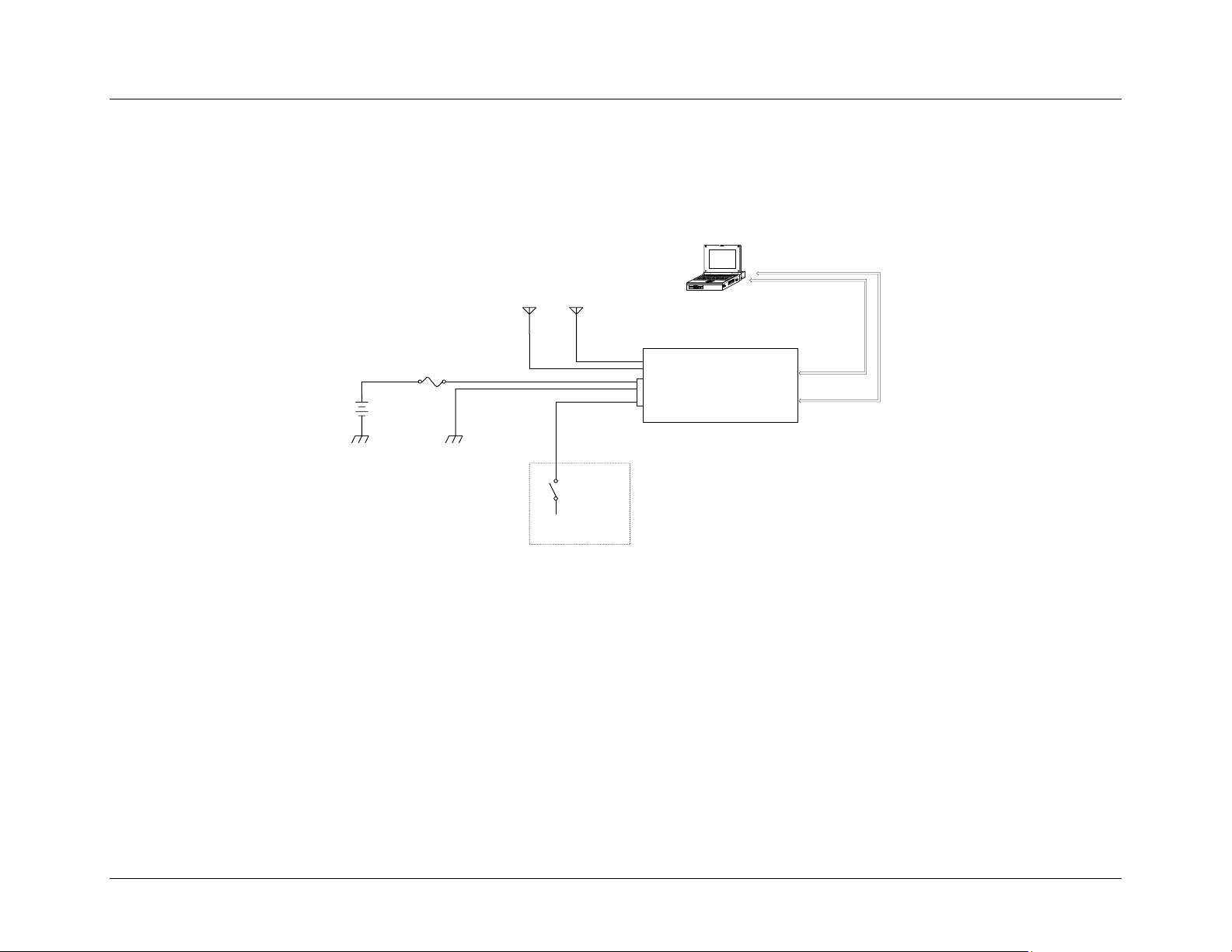
Docking Station Configuration
This configuration allows the power supplied to the modem to be controlled by a docking station that may be mounted inside the vehicle.
NOTE: Please refer to the manufacturer’s instructions for proper installation of your specific docking station.
MOBILE DA TA
COMPUTER
+12VDC
(FUSE D)
MODEM
ANTENNA
DOCKING
STATION
CONTROLLED
POWER
POWER /
IGNITION
+12VDC
VEHICLE
B ATTE RY
FUSE
GPS ANTENNA
(OPTIONAL)
Figure 10 – Docking Station Configuration
Mounting the Modem
Mount the modem as described for the standard mobile installation on page 28.
Mounting the Antenna(s)
Mount the antenna(s) as described for the standard mobile installation on page 30.
Route and Connect Ignition/Power
Route and connect the ignition/power cable as described in the following steps.
1. Determine a cable routing plan that will allow you to connect the DC power cable between the modem and the vehicle
battery. Connect the male end of the power cable to the 4-prong connector labeled IGN/PWR on the rear panel of the
modem.
iR1600
RS-232
GPS DATA
RS-232
MODEM DATA
nextel.com
37
Page 43

Installation Guide
2. Route the free end of the cable to the vehicle battery. If necessary, drill a hole in the vehicle firewall and route the cable
through it using the supplied grommet. (Refer to Figure 8 – Modem Power Wiring Diagram on page 32).
3. Locate an available chassis ground mounting point near the battery and shorten the black lead to remove any excess
cable length.
4. Crimp on the ring tongue terminal and connect the black lead directly to the chassis ground.
5. Position the fuse holder as close to the battery as possible, and away from any potentially hot components.
6. Mount the fuse holder by tie wrapping it to the other cabling wires and dress wires as necessary.
7. Shorten the red lead of the DC power cable to remove any excess length and crimp the fuse holder’s red lead to it using
the in-line splice.
8. Connect the ring tongue terminal from the fuse holder to the positive (+) battery terminal.
9. Connect the free end of the ignition wire to a fused +12VDC circuit controlled by the laptop/MDT docking station (see
Figure 10 on page 37). This circuit shall nominally output 12VDC @ 5mA when the modem is intended to be ON, and
0Vdc (open circuit) when the modem is intended to be OFF.
Route and Connect Antenna Cable(s)
Connect the antenna cable(s) as described for the standard mobile installation on page 33.
Route and Connect Data Cable(s)
Connect the data cable(s) as described for the standard mobile installation on page 33.
38
nextel.com
Page 44

FIXED INSTALLATION
This chapter includes instructions on how to install your iR1600 modem in a fixed (i.e. building/desktop) environment.
Installation Steps Page 39
Installation Guide
Mounting the Modem
Select Modem Location
Mount the Modem
Mounting the Antenna(s)
Approved Antennas
Select Antenna Location
Mount the Antenna(s)
Mount the Modem Antenna
Mount the GPS Antenna (optional)
Route and Connect Cables
Approved Cable
Route and Connect Ignition/Power Cable
Route and Connect Antenna Cable(s)
Route and Connect Data Cable(s)
Page 40
Page 40
Page 40
Page 40
Page 41
Page 41
Page 41
Page 41
Page 41
Page 42
Page 43
Page 43
Page 43
Page 43
Installation Steps
To install, you must complete the following steps:
• Mount Modem – Mount the modem in the desired location.
• Mount Antenna – Mount the antenna using the instructions included with your selected antenna’s installation guide.
• Route and Connect Power Cables – route the power cables from modem to the power supply.
• Connect Antenna Cable(s) – Connect cables to the mounted modem and antenna.
• Connect Data Cable(s) – Connect the data cables from the modem and GPS to the mobile device.
nextel.com
39
Page 45
Installation Guide
Mounting the Modem
The iR1600 modem can be mounted on different types of surfaces. You should determine if the surface is able to support the weight of the iR1600
modem. The area should allow sufficient space around the modem for cool air to circulate.
Select Modem Location
The iR1600 modem within a building or fixed environment is typically installed in an area where the antenna has a direct line-of-sight to the sky
for maximum reception.
Mount the Modem
The following steps describe how to mount the iR1600 data modem in a fixed environment.
1. Determine a convenient location within the fixed environment.
2. Use the iR1600 modem and mark the positions of the holes on the mounting surface.
3. Drill the holes in the marked location.
4. Mount the unit using the #10 sheet metal screws.
Mounting the Antenna(s)
The location of the antenna should be chosen carefully.
!
40
IMPORTANT: Things to consider when installing the antenna
equipment.
• Equipment must be installed in accordance with the
installation instructions.
• To ensure compliance with United States FCC regulations
on RF exposure, equipment must be installed in such a way
as to maintain a separation of at least 8 inches (20 cms)
between the antenna and the human body.
• Ensure that the antenna is properly installed external to the
vehicle and in accordance with the requirements of the
antenna manufacturer/supplier.
• Use only an approved antenna. Unauthorized antennas,
modifications or attachments could impair call quality,
damage the modem, or violate FCC mandates.
nextel.com
Page 46
Installation Guide
Approved Antennas – sold separately
For a list of tested and approved antennas that can be used with the iR1600 modems, please refer to the Aproved Components List on page 7 of
this document.
NOTE: Antennas with gain exceeding 5dBd (commonly specified as 3dB gain) do not comply with FCC RF exposure and are not allowed for use with this product.
Select Antenna Location
The antenna must be positioned where it has direct line-of-sight to the sky. In some cases, this can be accomplished by placing the antenna
adjacent to a window. In most cases it will require mounting outside of the building.
The cellular antenna(s) used for this transmitter must not
be co-located or operated in conjunction with any other
antenna or transmitter. This device is approved with
emissions having a source-based time-averaging duty
factor not exceeding 67.5%.
Antenna Installation:
• Antennas used for this transmitter must not exceed an
antenna of 5 dBd (commonly specified as 3dB gain).
• For rear deck trunk and rooftop installations, the antenna
must be located at least 20 cm away from rear-seat
passengers and bystanders in order to comply with the
FCC RF exposure requirements.
IMPORTANT: Failure to observe these restrictions will result in exceeding the
FCC RF exposure limits.
Mount the Antenna(s)
Mount Modem Antenna
The following steps describe how to mount an antenna.
1. Use an antenna suitable for the cellular band of frequencies (806-870 MHz) with Mini UHF jack and matched for 50ohm impedance.
2. Mount the antenna according to the manufacturer’s specifications or instructions.
NOTE: Each antenna has specific installation instructions. Please refer to the antenna installation instructions for specific requirements and details.
Mount GPS Antenna (optional)
The iR1600 GPS-Enabled modem is equipped with a connector for a GPS antenna. The following steps describe how to mount a GPS antenna.
nextel.com
41
Page 47
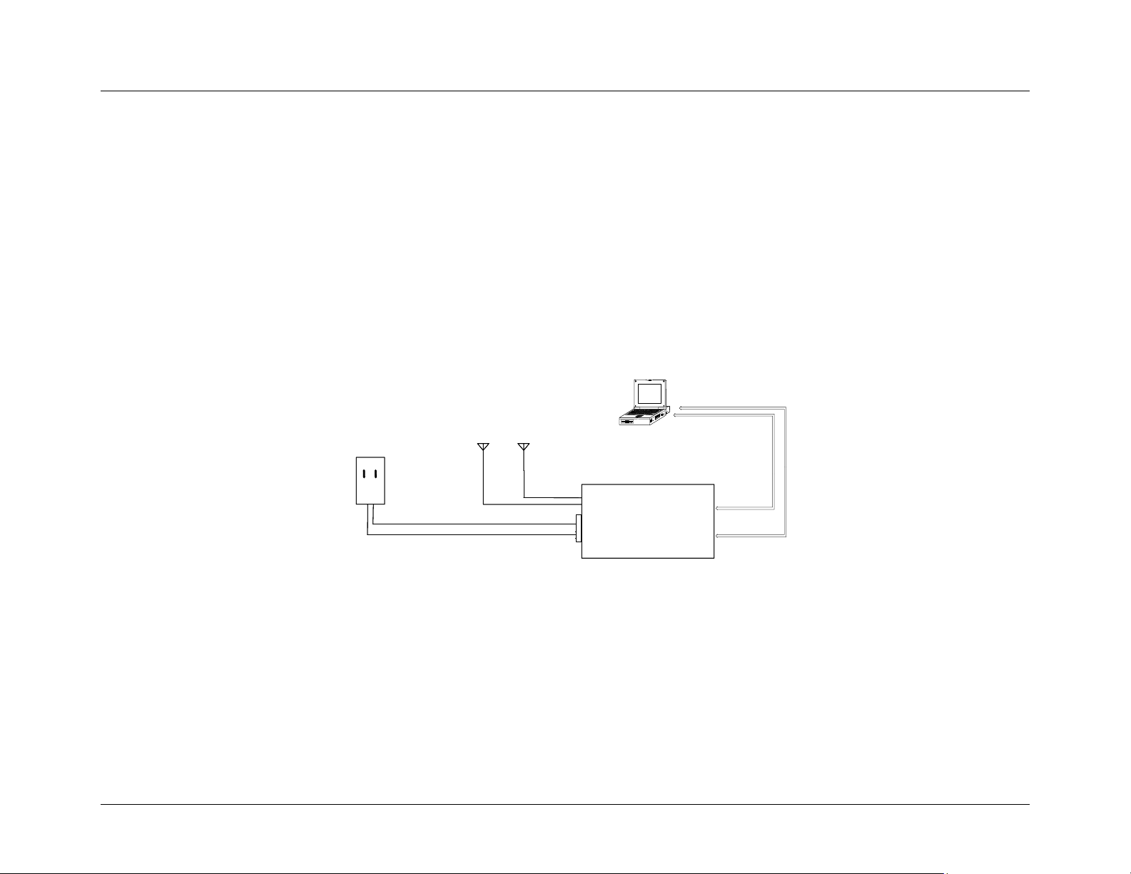
Installation Guide
1. Use an antenna suitable for the GPS of frequency 1575 MHz with an MCX connector and matched for 50-ohm
impedance.
2. Position the antenna where it has a direct line-of-sight to the sky.
3. Mount the antenna according to the manufacturer’s specifications or instructions.
NOTE: Because of the operating frequencies involved with the GPS signal, splicing or using adapters to extend the length of the antenna
coaxial cable is not recommended and will likely prevent the system from operating properly. We recommend using a single length of
coax without splices or adapters.
Route and Connect Cables
The following diagram illustrates typical installation wiring of the iR1600 in a fixed environment.
MOBI LE D ATA
MOBI LE D ATA
COMPUTER
COMPUTER
120VAC TO 12VDC
120VAC TO 12VDC
POWER CONVERTER
POWER CONVERTER
GPS ANTENNA
GPS ANTENNA
(OPTIONAL)
(OPTIONAL)
MODEM
MODEM
ANTENNA
ANTENNA
POWER /
POWER /
IGNITION
IGNITION
iR1600
iR1600
Figure 11 – iR1600 Installation Wiring Diagram (Fixed)
RS-232
RS-232
GPS DATA
GPS DATA
RS-232
RS-232
MODEM DA TA
MODEM DA TA
42
nextel.com
Page 48
Approved Cables – sold separately
The following DC power cable was designed specifically for use with the iR1600.
5260-C5-RFM – AC Power Adapter (iR1600)
5290-C5-RFM – AC Power Adapter (iR1600) for
Extended Temperatures
Installation Guide
!
IMPORTANT: Only approved and tested components should be used
with the iR1600 modem. Use of unapproved components violates the
modem’s warranty.
Route and Connect Ignition/Power Cable
The following steps describe how to route and connect the power cable:
1. Connect male end of the AC Power Adapter cable to the 4-prong connector labeled IGN/PWR on the rear panel of
the modem.
2. Connect the free end of the power cable to a 120VAC-power outlet.
Route and Connect Antenna Cable(s)
The following steps describe how to connect the antenna cables to the modem.
1. Insert the male end of the modem antenna cable to the connector labeled MODEM ANT on the rear panel of the
modem.
2. Insert the male end of the GPS antenna (optional) cable to the connector labeled GPS ANT on the rear panel of the
modem.
Route and Connect Data Cable(s)
The iR1600 modem can be connected to the host DTE equipment using a standard “straight through” 9-pin male to a 9-pin female serial cable.
nextel.com
43
Page 49
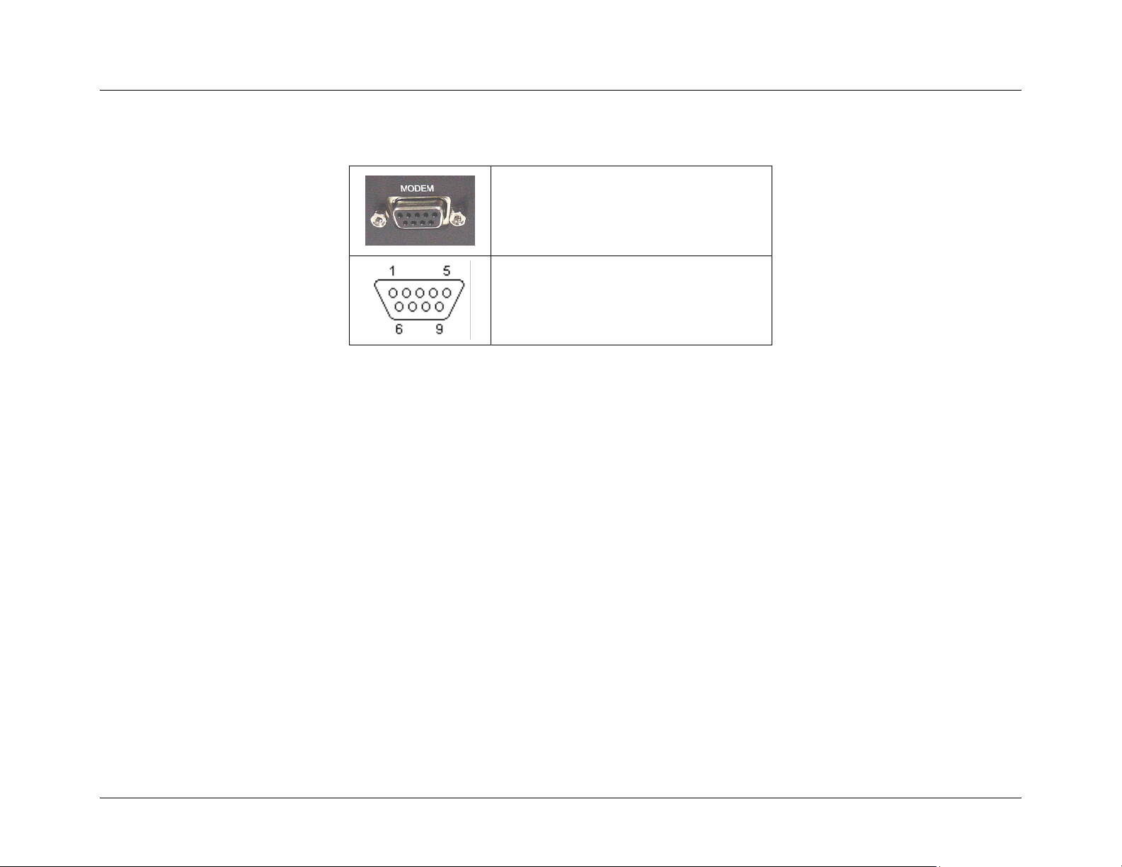
Installation Guide
Serial Connector (DB9) Pinouts
The following diagrams and table outlines the iR1600 RS232 pin assignments.
1. Data Carrier Detect (DCD)
2. Transmitted Data (TXD)
3. Received Data (RXD)
4. Data Terminal Equipment Ready (DTR)
5. Signal Ground (GND)
6. Data Communications Equipment Ready (DSR)
7. Request to Send (RTS)
8. Clear to Send (CTS)
9. Ring Indicator (RI)
The following steps describe how to connect the data cable:
1. Connect the 9-pin male end of the cable to the iR1600 MODEM communication connector, located on the rear panel
of the modem and the 9 pin female end of the cable to the data terminal equipment (DTE).
2. Connect the 9-pin male end of the cable to the iR1600 GPS communication connector, located on the rear panel of the
and the 9 pin female end of the cable to the data terminal equipment (DTE).
44
nextel.com
Page 50
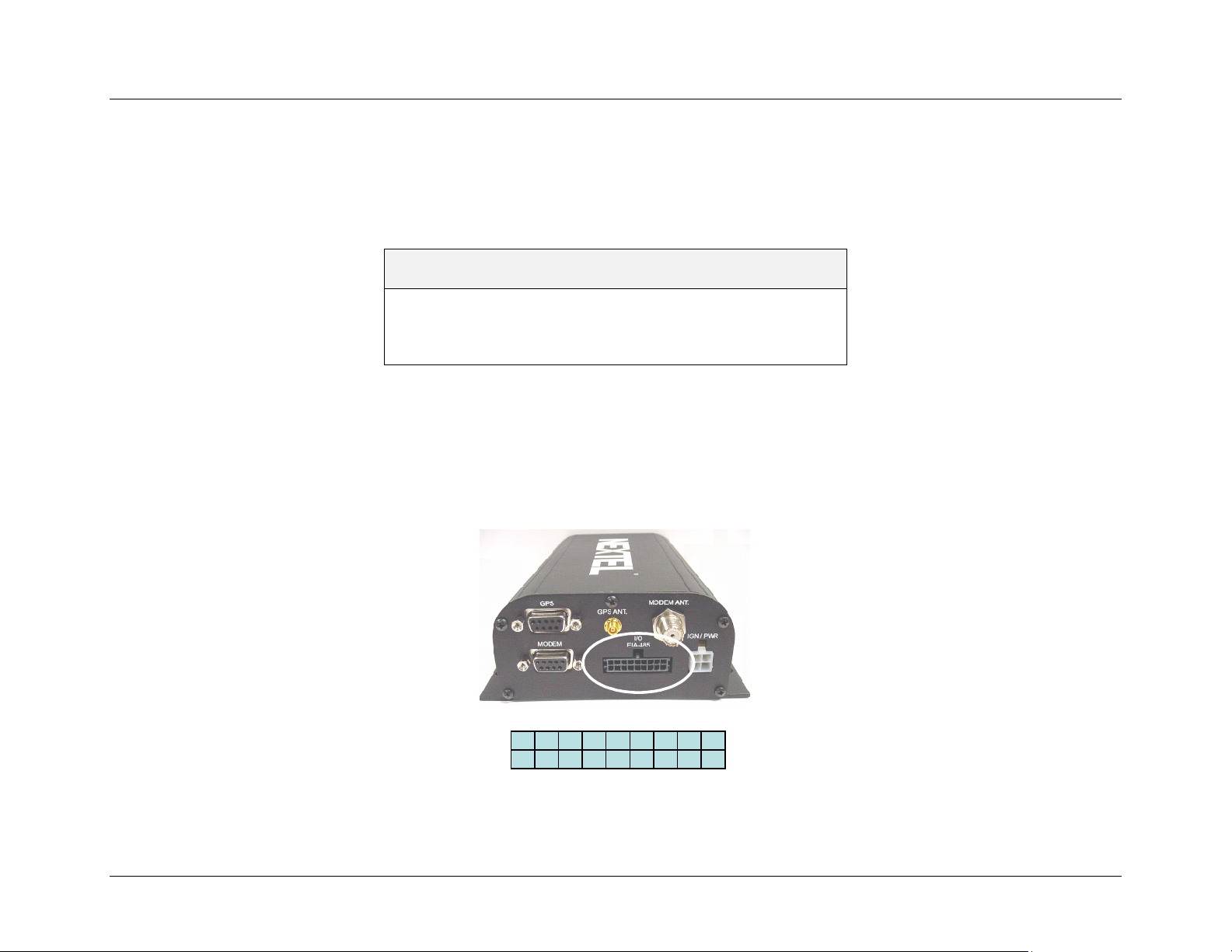
Installation Guide
CONNECTING I/O DEVICES
In this chapter, you will learn how to connect external I/O devices to the iR600 modem and configure them to communication with the modem.
This chapter includes:
Connector Pinouts
I/O Wiring Options
Wiring Options for Analog Inputs
Wiring Options for Digital Inputs
Page 45
Page 47
Page 47
Page 48
Connector Pinouts
The iR1600 modem currently provides two (2) channels of analog inputs that can be utilized to monitor a variety of 0-10VDC or 4-20mA
environmental sensors. The modem also provides three (3) channels of digital inputs that can be used to monitor Open/Gnd or +12v/Open
discretes.
There are currently 12 active pins that can be used to connector external I/O devices. These are indicated in the diagrams and table below.
Figure 12 – I/O Connectors on iR1600 Rear Panel
10
12
16
16
15
15
14
14
13
13
12
11
11
10
3456789
3456789
18
18
17
17
2
2
1
1
nextel.com
45
Page 51

Installation Guide
Connector
Pin
1 Analog Input 1 RTN
2 Analog Input 1
3 Analog Input 2 RTN
4 Analog Input 2
5 Digital Input 1 RTN
6 Digital Input 1
7 Digital Input 2 RTN
8 Digital Input 2
9 Digital Input 3 RTN
10 Digital Input 3
11 485B (reserved for future release)
12 485A (reserved for future release)
13 GND
14 +12Vdc
15 Digital Output1B (reserved for future release)
16 Digital Output1A (reserved for future release)
17 Digital Output2B (reserved for future release)
18 Digital Output2A (reserved for future release)
Signal
46
nextel.com
Page 52

I/O Wiring Options
Connect the desired sensors to the iR1600 using minimum 26 AWG wire as show in the diagrams below.
Wiring Options for Analog Inputs
4-20mA Sensor
4-20mA Sensor
Analog Input
Analog Input
External
External
External
Power
Power
Power
Supply
Supply
Supply
Analog Input Rtn
Analog Input Rtn
Installation Guide
External
External
External
Power
Power
Power
Supply
Supply
Supply
Figure 13 – Diagram for Connecting 4-20mA Sensors
0-10V Sensor
0-10V Sensor
Figure 14 – Diagram for Connecting 0-10V Sensors
nextel.com
Analog Input
Analog Input
Analog Input Rtn
Analog Input Rtn
47
Page 53
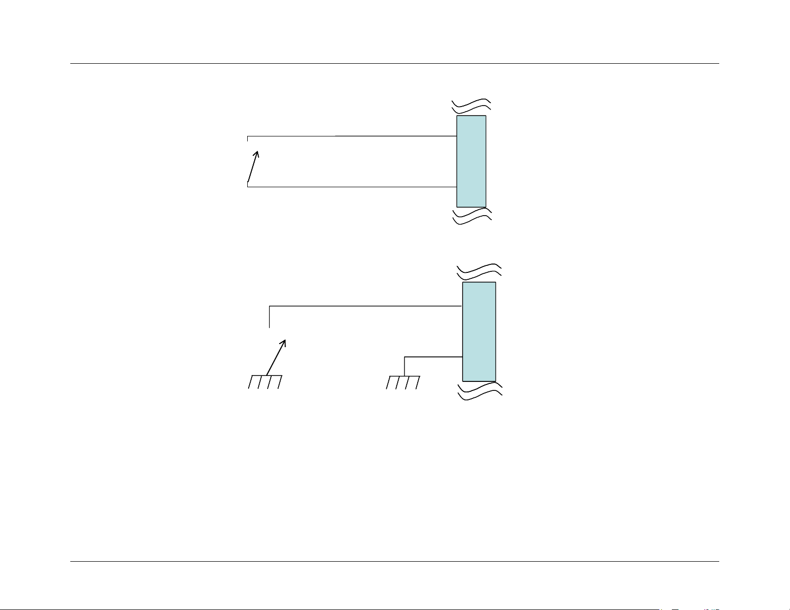
Installation Guide
Wiring Options for Digital Inputs
Digital Input
Digital Input
Digital Input Rtn
Digital Input Rtn
Figure 15 – Diagram for Connecting Open/Gnd Input Discrete
Vehicle +12v
Vehicle +12v
Chassis Ground
Chassis Ground
Figure 16 – Diagram for Connecting Open/Gnd Input Discrete
Vehicle Ground
Vehicle Ground
Digital Input
Digital Input
Digital Input Rtn
Digital Input Rtn
48
nextel.com
Page 54
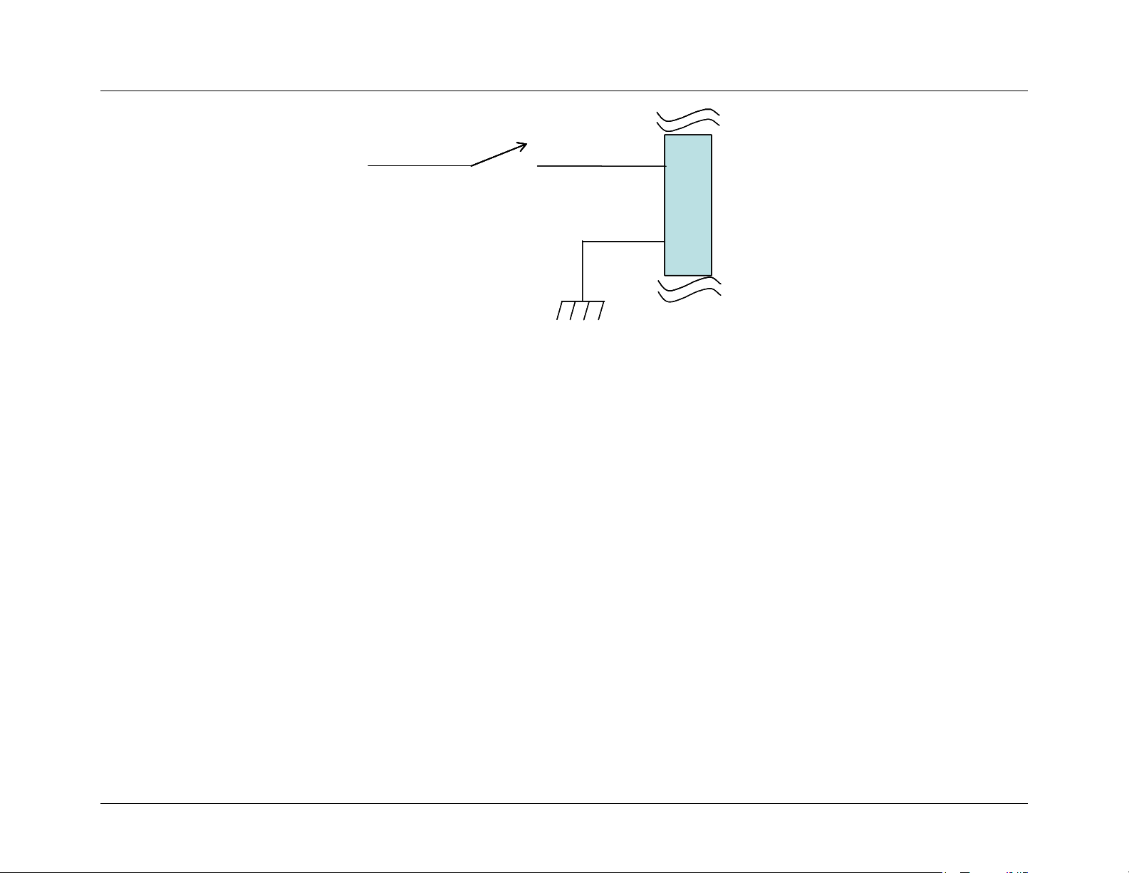
Installation Guide
Vehicle +12v
Vehicle +12v
Vehicle Ground
Vehicle Ground
Figure 17 – Diagram for Connecting +12V/Open Input Discrete
Digital Input
Digital Input
Digital Input Rtn
Digital Input Rtn
nextel.com
49
Page 55

Installation Guide
This page intentionally left blank.
50
nextel.com
Page 56

Installation Guide
VERIFYING INSTALLATION
Once you have installed the modem’s hardware components and connected all the power cables, you will want to power up the modem to ensure
that the installation was successful. This chapter contains instructions on how to verify that the installation of the iR1600 modem was
successful.
Communication Indicators
iDEN Network Status Indicators
Signal Status Indicators
Operating Mode Indicators
Verify Mobile Installation
Power up the Modem
Verify Communication
Verify Fixed Installation
Power up the Modem
Verify Communication
Page 51
Page 52
Page 53
Page 54
Page 54
Page 55
Page 55
Page 55
Page 55
Page 55
Communication Indicators
Your iR1600 modem is equipped with six (6) single color LED indicators (see Figure 18 on page 52) that identify the modem’s various
communication statuses and one (1) LED to indicate the status of the iDEN
(3) LEDs and the iR1600 Rugged modem has two (2) LEDs that indicate their mode of operation.
network. Additionally, the iR1600 GPS-Enabled modem has three
nextel.com
51
Page 57
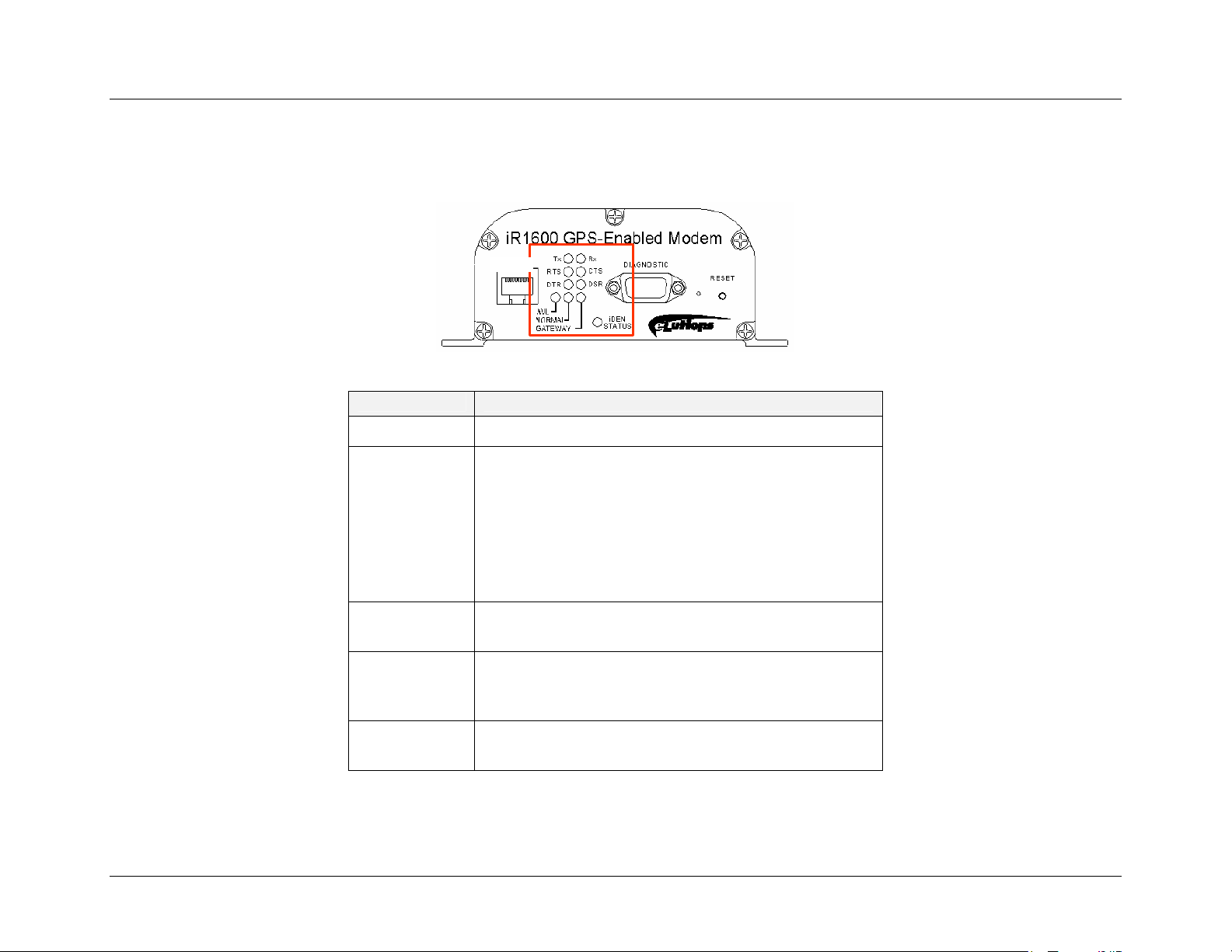
Installation Guide
iDEN
These LEDs and their statuses are described in the following table.
Network Status Indicators
Figure 18 – LEDs on Front Panel of GPS-Enabled Modem
Color Indication
Blinking Red Modem is attempting to connect to the iDEN network
Solid Red Out-of-Range – the modem is not connected to the
iDEN
network or is searching for signal within the
Nextel network. If the modem status changes from
blinking green back to solid red, the signal has been lost
and the modem is attempting to re-acquire.
NOTE: If after a period of several minutes the status does not
return to green, you may be out of range. The modem will attempt
to re-acquire automatically when you are back in range.
Blinking Green In-Range – the modem is connected to the iDEN
network.
Solid Green In Use – iDEN network communications is in progress.
This LED will only reflect solid green when the modem
is operating in circuit switched mode.
Off Off – vehicle ignition is off or has experienced loss of
12V input power.
52
nextel.com
Page 58
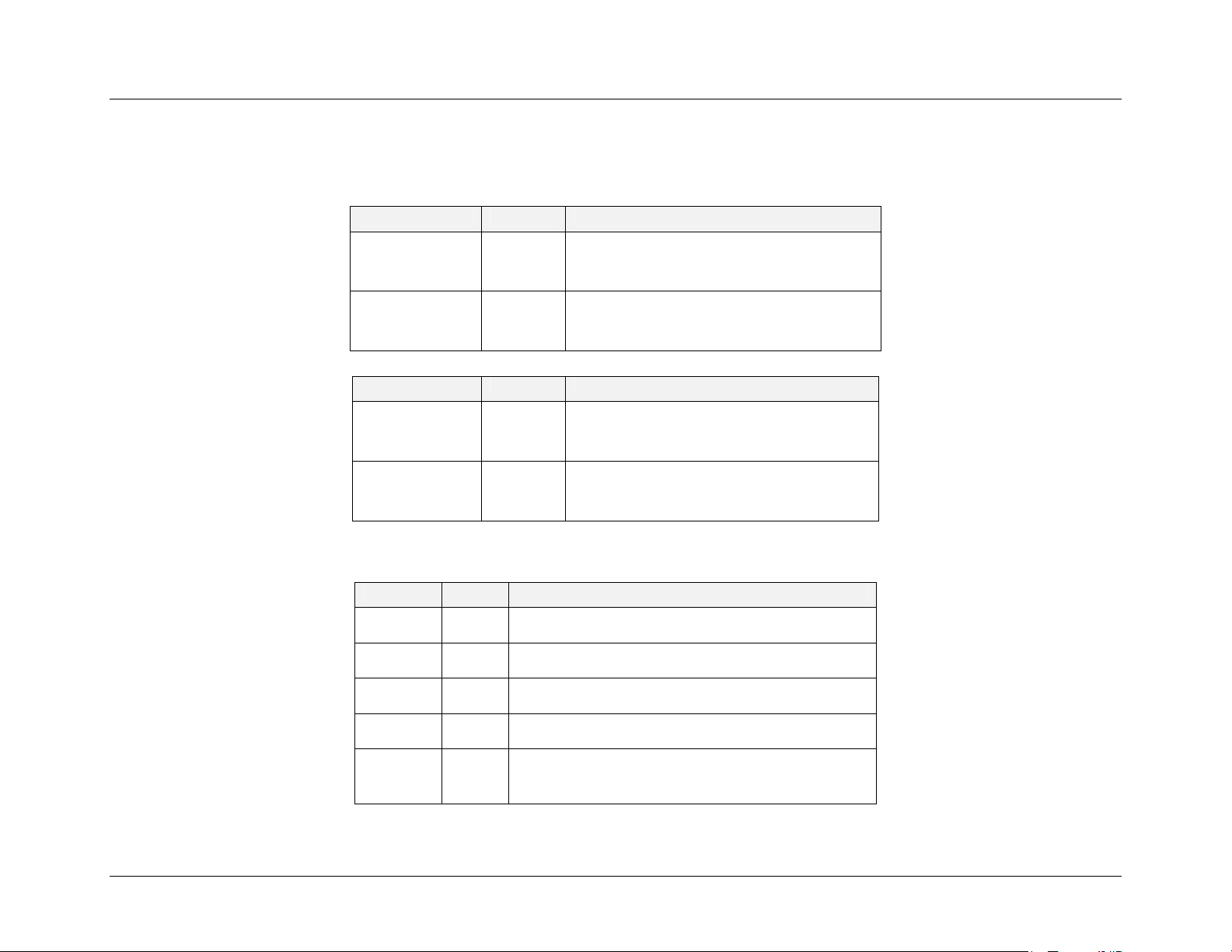
Installation Guide
The iDEN STATUS indicators differ, depending on the type of connection the modem is operating in. The following tables describe the iDEN
STATUS indicators for the Packet Data and Circuit Switched Data connection modes.
Packet Data
Signal Color Indication
In-range (modem is connected to the
iDEN
network) but idle (not passing
data).
The modem is in use – IDEN
network
communication is active and is passing
data.
In-range (modem is connected to the
iDEN
Network) but idle (not passing
data).
The modem is in use – iDEN
network
communication is active and is passing
data.
Circuit Switched Data
iDEN
STATUS
iDEN
STATUS
Blinking
Green
Blinking
Green
Signal Color Indication
iDEN
STATUS
iDEN
STATUS
Blinking
Green
Solid
Green
Signal Status Indicators
Signal Color Indication
Tx Green Modem is transmitting data to the host system.
Tx Off Modem is not transmitting data.
Rx Green Modem is receiving data from the host system.
Rx Off Modem is not receiving data.
RTS Green Request To Send from host system has been
asserted.
nextel.com
53
Page 59
Installation Guide
Operating Mode Indicators
Signal Color Indication
RTS Off Request To Send is not asserted.
CTS Green Clear To Send from modem is asserted.
CTS Off Clear To Send is not asserted.
DTR Green Host system is ready.
DTR Off Host system is not ready.
DSR Green Modem is ready.
DSR Off Modem is not ready.
Signal Color Indication
AVL
Normal
Gateway
Note: When the modem is in diagnostic mode, all of the operating mode indicators will be off.
Solid
Red
Solid
Red
Solid
Red
The modem is operating in AVL mode.
The modem is operating in Normal Mode.
The modem is operating in Gateway Mode.
Verify Mobile Installation
If ignition sense is utilized, the modem will automatically power-up when the vehicle’s engine is started. The following steps describe how to
power up the modem for a mobile installation and verify that the modem is successfully communicating within the iDEN
54
nextel.com
network.
Page 60

Installation Guide
Power up the Modem
1. Turn on the vehicle’s ignition.
2. The iDEN
within the iDEN
NOTE: The iDEN
STATUS LED light will initially blink Red. This indicates that the modem is searching for a signal
network.
Status LED should blink Green within 3 minutes from the time the vehicle’s ignition was turned ON.
Verify Communications
3. A blinking Green light indicates that a signal has been found the modem has successfully connected.
Verify Fixed Installation
To turn on the iR1600 modem, an ignition signal is required at the ignition connector. The ignition/power connector provides power and an
ignition signal to the modem. The following steps describe how to power up the modem for a fixed installation and verify that the modem is
successfully communicating within the iDEN
Power up the Modem
network.
1. Insert the ignition/power jack into the 4-prong IGN/PWR connector located on the rear panel of the modem (refer to
Figures 4 and 5 on Page 17).
2. Plug the AC power cord into a standard 2-prong polarized wall socket.
3. The iDEN
the Nextel
STATUS LED light will initially blink Red. This indicates that the modem is searching for a signal within
network.
Verify Communications
4. A blinking Green light indicates that a signal has been found the modem has successfully connected.
NOTE: The iDEN
Status LED should blink Green within 3 minutes from the time the vehicle’s ignition was turned ON.
nextel.com
55
Page 61

Installation Guide
This page intentionally left blank.
56
nextel.com
Page 62
CONFIGURING THE MODEM
IMPORTANT: Once the all the hardware for the modem is successfully installed, the next step is to configure the modem.
!
This process requires that you have knowledge of TCP/IP communication and modem operation. Please refer to the iR1600
Configuration Guide for detailed instructions on how to configure the iR1600 modem.
Installation Guide
nextel.com
57
Page 63

Installation Guide
This page intentionally left blank.
58
nextel.com
Page 64
pp
TROUBLESHOOTING
This chapter includes instructions on how to troubleshoot and resolve common installation problems.
Common Problems Page 59
Connect to Diagnostic Port Page 61
Installation Guide
Set up HyperTerminal Session
Modem Diagnostic Menu
Unsolicited Firmware Updates Page 67
Common Problems
The following table outlines the most common installation issues and instructions for resolution.
What’s the
Problem?
Nothing happens
when I power up
the modem.
The modem has
power but the LED
light is not blinking
green.
The modem
doesn’t a
ear to
What it means: How to Resolve:
This indicates that
there is no power
being supplied to the
modem.
- You may not be
within coverage
area.
- Signal strength
may be weak.
This could indicate a
number of things (see
There are several things that could be wrong. Go through
this list and eliminate all the possible problems:
• Is the ignition on?
• Check the power supply and make sure that everything
is connected properly.
• Is the battery voltage at least 12 volt?
• Check the cables and wiring.
• Antenna may be loose. Check to make sure the antenna
is properly connected.
• Reposition antenna.
• Is the data cable plugged into the diagnostic port?
Page 61
Page 64
nextel.com
59
Page 65

Installation Guide
What’s the
What it means: How to Resolve:
Problem?
be communicating. How to Resolve
column to eliminate
the possibilities).
GPS does not
operate.
Either:
- Coverage in the
area is bad.
- Antenna may be
improperly
installed or
defective.
• Is the data cable connected properly to the mobile
device or computer?
• Check that the iDEN status LED is blinking green.
• Verify signal quality (option 3 on Diagnostic Menu).
• Check that the modem has been
• Verify signal strength (option 4 on Diagnostic Menu).
• Check the RSSI.
• Check coverage.
• Move to another location to see if coverage is not
affected.
• Verify that the packet data has been registered (option 5
on Diagnostic Menu).
• Verify that your account has been activated. Contact
your technology administrator or designated field care
representative.
• Perform a master reset then check option R on the
Diagnostic Menu and make sure that the modem is
registered.
• Verify that the antenna has direct line of sight to
satellite. GPS does not operate effectively indoors.
• Move to another area.
60
nextel.com
Page 66
Installation Guide
What’s the
Problem?
GPS is slow. It is normal for GPS
Modem will not
power up or down
What it means: How to Resolve:
• Wait for an appropriate amount of time for
to take up to 5
minutes to acquire the
first reading.
The wiring to the
modem may not be
connected properly.
communication to take place. If attempts are taking
longer than 5 minutes, contact your system
administrator.
• Check the ignition sense wiring to be sure that it is
connected.
• Verify that the diagnostic port is plugged in correctly.
• Check iDEN
STATUS LED to see if the modem is
communicating.
NOTE: The Status LED remains red for up to 3 minutes after power is applied to the iR1600 or immediately after the Reset button
is pressed.
Connect to Diagnostic Port
The diagnostic port located on the front panel of the iR1600 modem (see Figures 2 or 3 on page 16) is used to retrieve data from the modem that
will help to analyze and diagnose possible communication issues. The following steps describe how to connect to the diagnostic port:
1. Insert the 9-pin male end of a serial signal cable into the RS-232 connector labeled DIAGNOSTIC port located on the
modem’s front panel, and tighten the screws.
2. Connect the other end of the serial signal cable to a serial COM port on the back of your computer or mobile device
and tighten the screws.
Set up HyperTerminal Session
The following steps describe how to set up a HyperTerminal session for the iR1600 modem:
1. From your computer, locate and select the HyperTerminal program.
nextel.com
61
Page 67
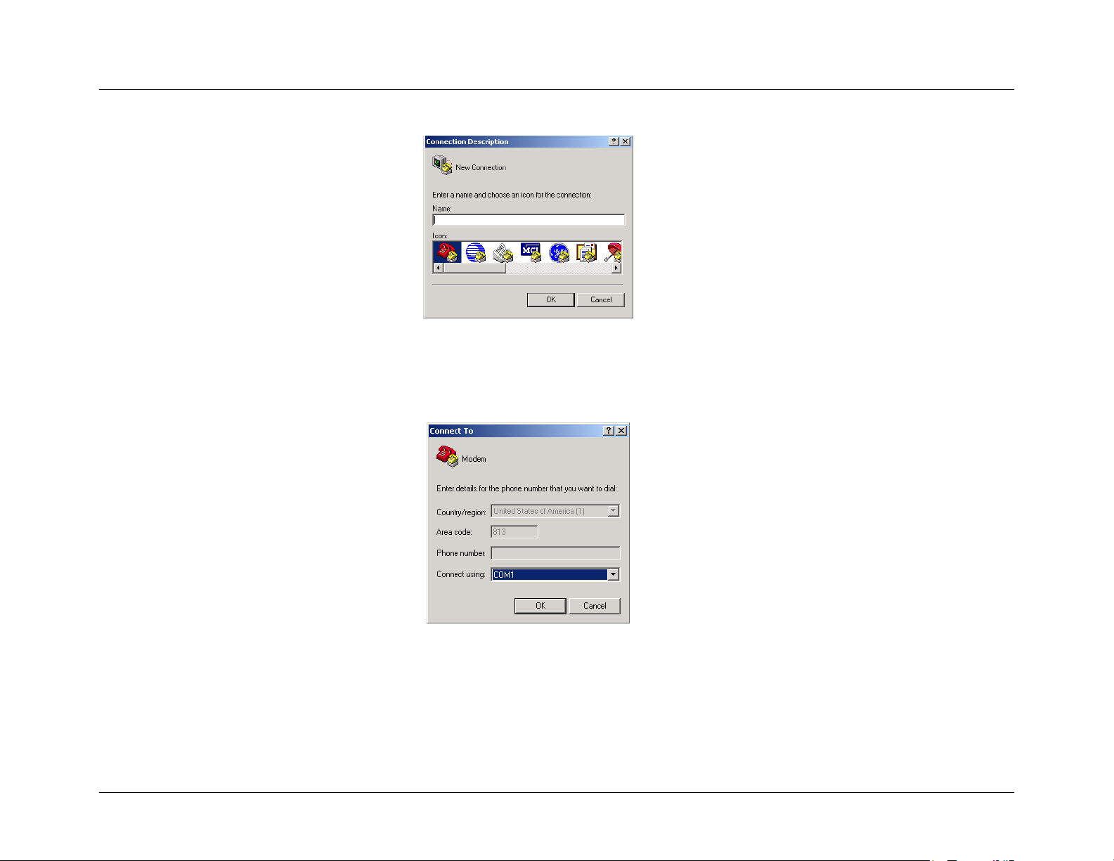
Installation Guide
2. The Connection Description screen appears.
3. Type a description of the connection in the “Name:” box (i.e. iR1600).
4. Select the dial function (red and yellow phone icon) and click OK.
5. The Connect To screen appears.
6. Select the appropriate communication port (typically COM1) from the “Connect Using:” drop-down list then Click
OK.
62
nextel.com
Page 68
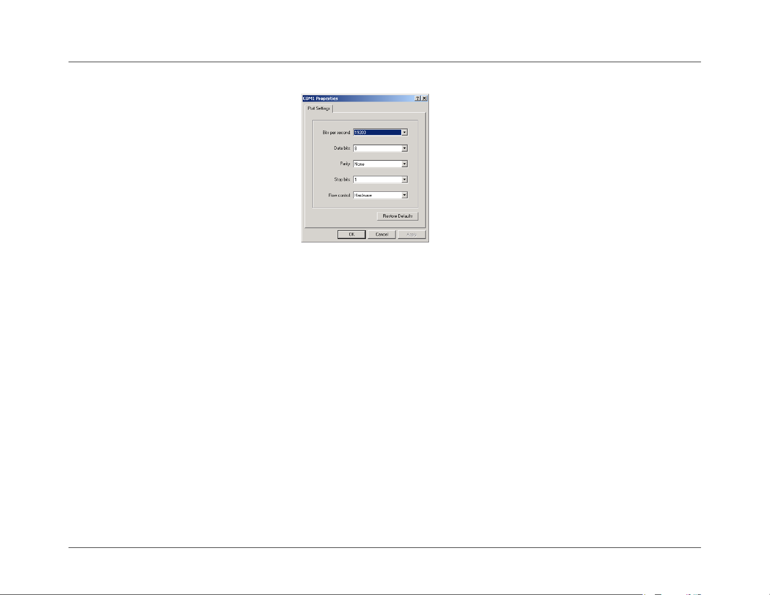
Installation Guide
7. The COM1 Properties screen appears.
8. Select the following parameters from each of the drop-down lists on the Port Settings tab:
•••• 19200 for Bits per second
•••• 8 for Data bits
•••• NONE for Parity
•••• 1 for Stop bits
9. None or Hardware for Flow control
10. Click OK when all the parameters have been selected.
nextel.com
63
Page 69
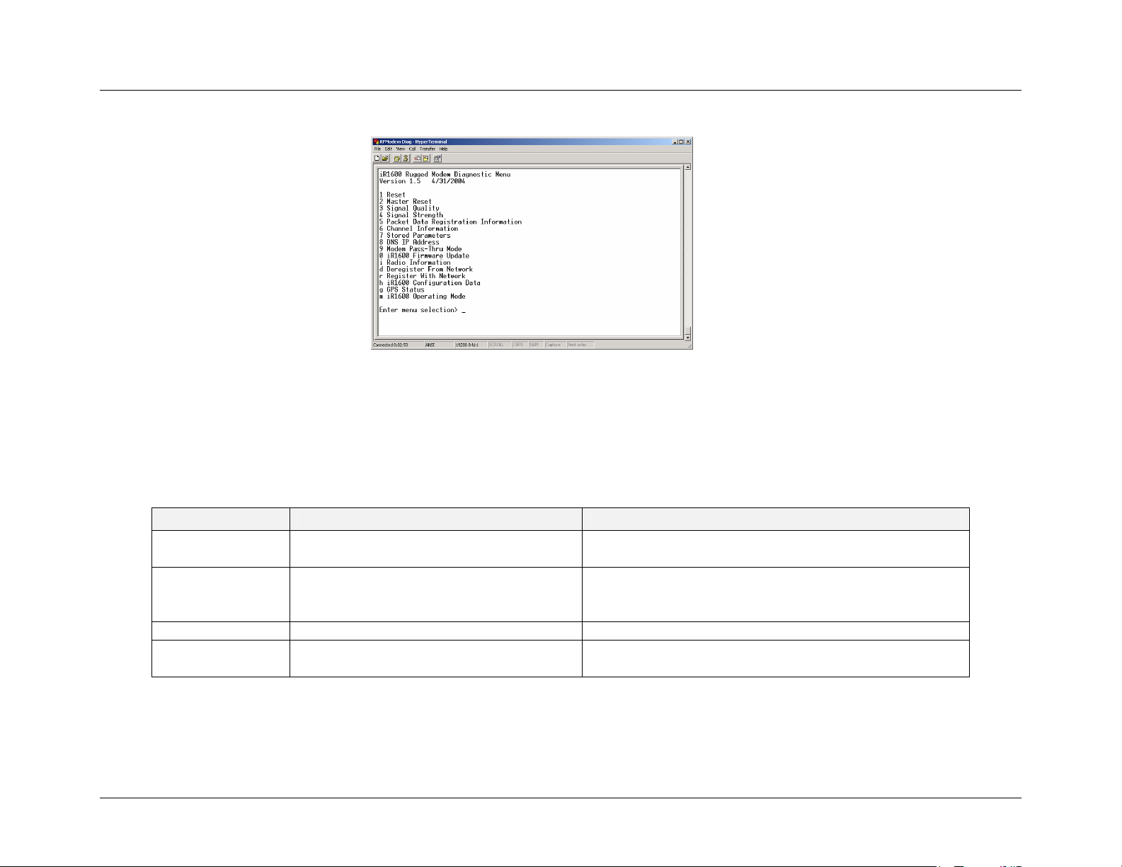
Installation Guide
11. Once the connection to the modem is successful, the iR1600 Rugged Modem Diagnostic Menu appears.
12. Click on File and Save as. Name this HyperTerminal Session (i.e. “iR1600 Modem Diagnostics”) and save to your
desktop for future use.
Modem Diagnostic Menu
The following table outlines the types of information that can be retrieved with commands on the diagnostic menu.
Command Action Reply
1 – Reset This command performs a soft reset to the
modem via RALP commands.
2 – Master Reset This command is used when certain
changes are made to the firmware and the
modem needs to acquire the changes.
3 – Signal Quality This determines the quality of the signal. Signal quality can be 0 – 100.
4 – Signal Strength This determines the signal strength of the
modem.
WARNING: We do not recommend that you perform this
command unless otherwise instructed by a Nextel
Customer Care representative.
Signal strength can be 0 – 100.
64
nextel.com
Page 70

Installation Guide
Command Action Reply
5 – Packet Data
Registration
Information
6 – Channel
Information
7 – Stored
Parameters
8 – DNS IP
Address
9 – Modem Pass-
Thru Mode
This will check for packet data registration
status.
This determines if channel data has been
obtained.
This provides the modem’s preset
parameters.
Displays the address of the Domain Name
Server.
Allows you to issue Hayes compatible AT
commands to the modem through the
diagnostic port.
• Service type: PACKET
• VALID NEI: (IP Address of the Modem)
• Registration Status: REGISTERED or
UNREGISTERED
• MIP Registration Status: REGISTERED or
UNREGISTERED
• Area
• RSSI
• Channel
• State
• TX Level
• Flow Control
• Character Framing
• Service Class
• DTE-side Stack
• WDS-side Stack
• Mobile IP Activation
• Mobile UP Registration Lifetime
• Security Parameter Index
• Home Agent IP Address
• +WPNEI Prefix Length
• Request Broadcast Datagrams
• DCE IP Addresses
• DTE IP Addresses
• Data Encryption
• Data Compression
• Header Compression
nextel.com
65
Page 71

Installation Guide
Command Action Reply
0 – iR1600
Firmware
Update
i – Radio
Information
d – Deregister
From Network
r – Register with
Network
H – iR1600
Configuration
Data
g- GPS Status Provides the modem’s GPS information.
m – iR1600
Operating Mode
Sends updates to the firmware. WARNING: We do not recommend that you perform this
command unless otherwise instructed by a Nextel
Customer Care representative.
Obtains information specific to the modem.
• Serial Number
• IMEI
• SIM ID
• Software Version
Forces the modem to deregister from the
DEREGISTERED
Nextel Network.
Forces the modem to register with the
REGISTERED
Nextel network.
Provides the modem’s build configuration
information.
• Hardware Part ID
• Serial number
• Boot Loader
• Application ID
• UTC
• Latitude
• Longitude
• Fixed Type
• Satellites Used
Allows for verification and configuration of
the modem’s operating mode. (Refer to
Configuration Guide for details of the
menus and options).
• Operational Mode (Normal, Gateway, AVL)
• Gateway/AVL Protocol Mode
• TCP/UDP Configuration
• DTE Port Configuration
• PAD Configuration
• AVL Configuration
• Send Device ID
• Remote Support Configuration
• Security Configuration
• BSAP Router Configuration
• Ignition Shutdown Delay
66
nextel.com
Page 72
Installation Guide
Unsolicited Firmware Updates
We want to emphasize that this diagnostic option should be executed only when instructed by a Nextel® Customer Care Representative. However,
there are certain sequences of events that will prompt you for a firmware update.
IMPORTANT: The following lists the sequence of events that
!
will cause HyperTerminal to prompt you for firmware update.
The following steps describe how an unsolicited firmware update is trigger and how to correct the problem.
1. Modem is OFF (all cables are connected except for the power connector).
2. The computer is ON and the HyperTerminal is active.
3. Modem is switched ON (power connector is inserted into the power slot).
nextel.com
67
Page 73
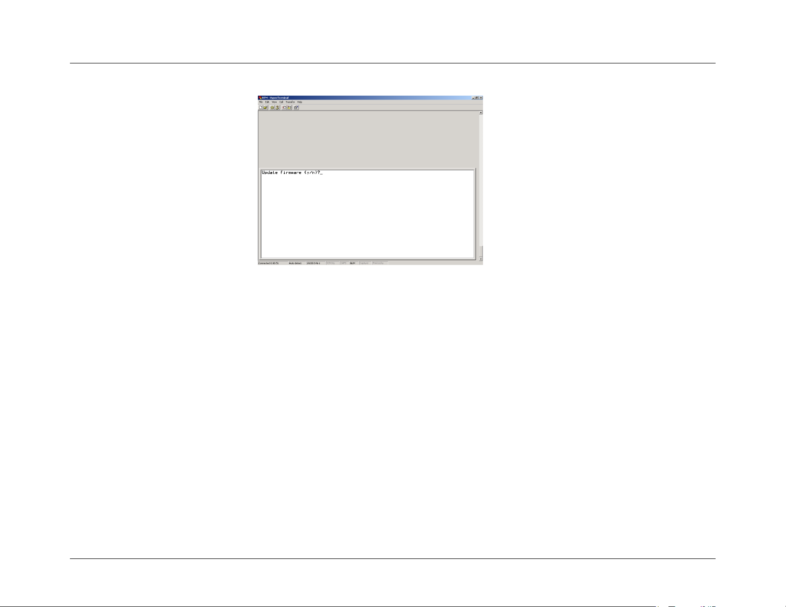
Installation Guide
4. HyperTerminal automatically presents the option 0 – Update Firmware (y/n)? prompt.
5. To safely exit out of the update firmware mode, enter “N” at the Update Firmware (y/n)? prompt. There will be
about a 1-minute delay before the system returns you to the diagnostic menu. This because the modem is attempting
to register with the iDEN network.
6. Once the modem has successfully registered with the network, the HyperTerminal will present you with the
Diagnostic Menu.
68
nextel.com
Page 74

Installation Guide
SAFETY NOTICE
The following information is important for the safe and efficient operation of the iR1600 modem. Please read this safety
notice before operating the modem.
Safe and Efficient Operation Guidelines
Your modem contains a transmitter and receiver. When it is ON, it receives and transmits radio frequency (RF) energy. The modem operates in the
frequency range of 806 MHz to 870 MHz and utilizes the digital modulation techniques. This product is authorized by FCC Rule Part 47CFR2.989
(b) which states that it should be used in such a way that it maintains a distance of at least 8 inches (20 cms) between the human body and the
radio's antenna or modem. When you use your modem, the system handling your call controls the power level at which your modem transmits.
The output power level typically varies from 0 mW to 700 mW.
Exposure to Radio Frequency Energy
Your modem is designed to comply with the United States Federal Communications Commission, Code of Federal Regulations; FCC part 90-sub
part S, and FCC-part 15, Class B. The modem complies with FCC’s national standards and guidelines regarding exposure of human beings to
radio frequency electromagnetic energy.
Medical and Personal Electronic Devices
Most electronic equipment is protected from RF energy. However, certain equipment may not be shielded against RF signals being emitted from
your modem.
Pacemakers
Operators should not use the modem if individuals with pacemakers are within 6 inches (0.15 meters) of the antenna.
Hearing Aids
The modem may interfere with hearing aid devices. Individuals who experience such interference should consult the hearing aid manufacturer
to discuss alternative solutions.
Other Medical Devices
Individuals who have other medical devices not specifically mentioned in this safety notice should consult their physician or the manufacturer
of the device to determine if it is adequately protected from external RF energy.
Interference with Other Electronic Devices
RF energy may affect improperly installed or inadequately protected electronic operating and entertainment systems in motor vehicles. Check with
the manufacturer or representative to determine if these systems are adequately shielded from external RF energy. It is recommended that you also
check with the manufacturer of any equipment that has been added to the vehicle.
nextel.com
69
Page 75

Installation Guide
This page intentionally left blank.
70
nextel.com
Page 76

Installation Guide
APPENDIX A: GLOSSARY
This glossary contains terms and definitions used within this guide. It is by no means exhaustive of terms that you may come across.
ASCII
American Standard Code for Information Interchange. A standard set of 128 characters, symbols and control codes used for computer communications. ASCII
characters require 7 bits of data to send, but are often sent 8 bits at a time with the extra bit being a zero.
Asynchronous Communication
A method of sending data in which the bits can be sent at random times. Data transmission is not synchronized to a clock. With asynchronous transmission, each
character is transmitted one at a time with a “start” bit at the beginning and one or more “stop” bits at the end. Any amount of time can elapse before the next
character can be sent.
AT Command
An order entered into the computer to request your modem to perform certain actions, such as dial a telemodem number. AT commands are Hayes-compatible
modem commands.
Baud
The signaling rate of a line, which is the number of transitions (voltage or frequency changes) that are made per second.
Baud Rate
Signaling speed of the modem. Common baud rates are 2400, 4800, 9600, 19200, and 56k.
Byte
A data unit of eight bits.
Circuit Switched Data
A networking technology that provides a temporary, but dedicated, connection between two stations no matter how many switching devices the data is routed
through. Circuit Switch was originally developed for the analog-based telephone system in order to guarantee steady, consistent service for two people engaged
in a phone conversation.
Command Mode
The mode that accepts AT commands. Also known as Terminal Mode. When your modem is in this mode, it is waiting to receive AT commands that you type
from your communication software.
Communication Software
A computer program designed to connect your computer to an external source, such as another computer or a fax machine.
nextel.com
71
Page 77

Installation Guide
Configuration
The term configuration defines the hardware components that comprise a subsystem and system. It is a set of conditions or parameters that define the structure of
an item such as the GPS processing and characteristics of the RS-232 interface ports.
Data Services
One of the functions of your iDEN modem. Data services uses both circuit-switched and packet data transmissions.
DCD
Data Carrier Detect. An acceptable carrier signal received by the modem over the modem line. Also known as Received Line Signal Indicator (RLSI).
DCE
Data Communication Equipment. The equipment that establishes, maintains, and terminates a connection. It converts data into units of sound and vice versa for
communication over telemodem or cellular networks.
Default
A factory preset choice that, under normal circumstances, works best for your system. You can either accept the default or change it.
Differential Capable
A term used to describe a GPS receiver capable of receiving and applying differential GPS corrections.
Differential GPS
A procedure of correcting GPS solutions to achieve improved position accuracy. Differential GPS provides 2 to 5 meter position accuracy. Differential accuracy
is obtained by applying corrections determined by the stationary Differential Reference Station to the GPS data collected by the RPU (receiver processing unit)
on-board the vehicle.
DNS
Domain Name Server. This is what converts names of domains (ex. : www.nextel.com) into IP addresses (ex. : 170.206.225.22). The DNS server that you use is
generally situated with your access provider.
DTE
Data Terminal Equipment. A computer or hand-held device that generates and receives data, and provides functions that control data communications through a
device like the modem.
Dial Up Networking (DUN)
A component in Windows that enables you to connect your computer to a network via modem. If your computer is not connected to a LAN and you want to
connect to the Internet, you need to configure Dial-Up-Networking (DUN) to dial a Point of Presence (POP) and log into your Internet Service Provider (ISP).
Your ISP will need to provide certain information, such as the gateway address and your computer’s IP address.
72
nextel.com
Page 78

Installation Guide
Firmware
A set of software computer/processor instructions permanently or semi-permanently resident in read-only memory.
Frequency
The number of vibrations per second of an audio or radio signal. Measured in hertz (Hz), Kilohertz (kHz), or megahertz (MHz). GPS frequencies are L1=
1575.42 MHz or L2= 1227.60 MHz.
GPS
(Global Positioning System) is a "constellation" of 24 well-spaced satellites that orbit the Earth and make it possible for people with ground
receivers to pinpoint their geographic location. The location accuracy is anywhere from 100 to 10 meters for most equipment. Accuracy can be
pinpointed to within one (1) meter with special military-approved equipment. The GPS is owned and operated by the U.S. Department of Defense
but is available for general use around the world.
GPS Antenna
An antenna designed to receive GPS radio navigation signals.
GPS Processor
An electronic device that interprets the GPS radio navigation signals (received by the GPS antenna) and determines a location solution. The GPS processor may
also be able to apply (and determine) differential GPs corrections.
GPS Receiver
The combination of GPS antenna and GPS processor.
Hand-Held Devices
Small computing appliances, such as palmtops, personal digital assistants and pen-based computers.
Hertz (Hz)
A frequency unit equal to one cycle per second.
Home Agent
The carrier or router responsible for determining the next network point to which a packet (data) should be forwarded toward its destination.
Internet
A series of interconnected local, regional, national and international networks, linked using TCP/IP. The Internet links many government, university, research
and commercial sites. It provides e-mail, Web browsing and file transfer services.
Internet Service Provider (ISP)
Provides your computer with Internet access. Also known as Service Provider.
nextel.com
73
Page 79

Installation Guide
Intranet
A network based on TCP/IP protocols (an internet) belonging to an organization, usually a corporation, accessible only by the organization’s members,
employees or others with authorization. An Intranet’s Web sites look and act just like any other Web sites, but the firewall surrounding an intranet fends off
unauthorized access.
Kbps
Kilobits per second. Generally represented at 1000 bits per second.
Laptops
Portable computers, such as notebooks and sub-notebooks.
Local Area Network (LAN)
A computer network that spans over a relatively small area. Most LANs are confined to a single building or group of buildings.
Mobile IP
An IP enhancement that provides forwarding of traffic to moving users. It uses agents in the user’s home network and in all foreign networks. When logging on
to a remote network, users register their presence with the foreign agent, and the home agent forwards the packets to the remote network. Mobile IP permits
mobile devices to inform a “visited” network that it is present and then arrange to have its home network forward data to it automatically.
Modem
An electronic device enabling digital data to be sent over analog transmission facilities. Converts a digital signal to analog and back to digital again. Modem
stands for Modulator/De-Modulator.
NMEA
National Marine Electronics Association. An association that defines marine electronic interface standards for the purpose of serving the public interest.
Non-Routable IP
A communications protocol that contains only a device address and not a network address. It does not incorporate an addressing scheme for sending data from
one network to another. Examples of non-routable protocols are NetBIOS and DEC’s LAT protocols. Also some TCP’IP addresses are considered non-routable.
Non-Volatile Memory
Memory that holds its content without power. Permanently stored information that is not lost when you power off. ROMs, PROMs, EPROMs and flash memory
are examples.
Packet of Data
A bundle or block of data, organized in a specific way for transmission.
74
nextel.com
Page 80

Installation Guide
Parallel Port
A low speed port, usually located on the rear of a computer which usually connects to printers. Parallel ports transmit data simultaneously over eight “parallel
wires” one byte at a time (as opposed to a serial port, which transmits data one bit at a time).
Parity Bit
Parity is a process for detecting whether bits of data have been altered during transmission. A Parity Bit is a non-data bit that is added to a group of data bits to
check for transmission errors. Parity Bits are used in Parity checking which is an error-checking method in asynchronous transmission. The parity bit tells the
receiving end of a transmission whether there should be an even or odd number of bits contained in that transmission.
PIN
Personal Identification Number.
PING
(Packet INternet Groper) An Internet utility used to determine whether a particular IP address is online. It is used to test and debug a network by sending out a
packet and waiting for a response. A program used to test whether or not a network component is available.
PPP
(Point-to-Point Protocol) The most common method for connecting to the Internet. PPP provides serial line (dial-up) connectivity, authentication, compression
and encryption between two computers and can handle several protocols simultaneously.
Protocol
Hardware and software standards that govern transmission between two communications devices. There are several layers, or levels, of functionality in a
protocol. Each layer may be available, as a separate software component, or several layers may be combined into one.
Public IP Address
See Routable IP Address.
RAM
Random Access Memory is the working memory of the computer where you can enter information and call up data.
Routable IP Address (Public IP Address)
A communications protocol that contains a network address as well as a device address, allowing data to be routed from one network to another. Examples of
routable protocols are SNA, OSI, TCP/IP, XNS, IPX, AppleTalk and DECnet.
RS-232
A communication standard for digital data. Specifies a number of signal and control lines. RS-232 is often associated with a 25-pin connector called DB-25.
nextel.com
75
Page 81

Installation Guide
Serial Port
An input/output (I/O) port transmits data one bit at a time, as opposed to a parallel port that transmits multiple (usually eight) bits simultaneously. RS232C is a
common serial interface standard.
Service Specific Software
A program designed for a designated online service such as AOL.
Start Bit
A data bit used in asynchronous transmission to signal the beginning of the character.
Stop Bit
A data bit used in asynchronous transmission to signal the end of the character.
System Administrator
The person responsible for monitoring computer activity in a specified area, such as a company.
Synchronous Communication
A method of sending digital data in which the bits come at fixed, rather than random, times and are synchronized to a clock.
TCP/IP (Transmission Control Protocol/Internet Protocol)
The two best-know Internet protocols, often erroneously thought of as one protocol. TCP enables two hosts to establish a connection and exchange streams of
data. TCP guarantees delivery of data and guarantees that packets will be delivered in the same order in which they were sent. IP acts as a postal system, allowing
you to address a package and drop it in the system, but doesn’t provide a direct link between you and the recipient. TCP/IP, on the other hand, establishes a
connection between two hosts so that they can send messages back and forth for a period of time.
Terminal Mode
The mode that accepts AT commands. Also known as Command Mode. When your modem is in this mode, it is waiting to receive AT commands that you type
from your communications software.
Transmission Rate
The rate at which data is transferred measured in bits per second. Common transfer rates are 9.6bps / 19200bps / 57600bps / 115200bps
UTC
Universal Time Coordinated. Uniform atomic time system/standard that is maintained by the US Naval Observatory. UTC defines the local solar mean time at
the Greenwich Meridian.
UTC Offset
The difference between local time and UTC (Example: UTC – EST = 5 hours).
76
nextel.com
Page 82

INDEX
3
3dB · 24, 29, 41
5
5 dBd · 24, 29, 41
A
Access Control List (ACL) · 14
AVL · 14, 15, 19, 54, 66
B
Installation Guide
Customer Care · 11, 64, 66
D
Data Account Activation · 9
Data bits · 63
Data Encryption · 65
DCD · 72
DCE · 72
Deregister · 66
desktop installation · 39
diagnostic · 64, 65
diagnostic port · 61
DNS IP Address · 65
DSR · 54
DTE · 33, 34, 43, 44, 65, 66, 72
DTR · 54
Bits · 63
Bristol Babcock · 14
BSAP · 14
building installation · 39
C
Channel Information · 65
chassis ground · 32, 36, 38
Circuit data · 15
coaxial cable · 30, 42
COM1 · 63
Config Data · 66
Coverage · 5, 11
CTS · 54
E
Electronic Devices · 69
Encryption · 18
F
FCC · 19, 24, 29, 30, 40, 41
Firmware Update · 66
Flow control · 63
nextel.com
77
Page 83

Installation Guide
G
Gateway · 14, 54, 66
GPS · 30, 41, 42
GPS Loop Back · 14
H
Hayes · 15, 65
Hearing Aids · 69
Heat · 22
human body · 29, 40
HyperTerminal · 21, 59, 61, 64, 67, 68
I
I/O Interfaces · 14
IGN/PWR · 32, 35, 37, 43, 55
ignition signal · 55
IP address · 14, 15
L
N
NMEA · 15, 19
Normal · 15, 54, 66
O
Operating Mode · 19, 51, 54, 66
P
Pacemakers · 69
Packet Data · 15, 65
Packet Data Applet · 9
PAD · 66
Parity · 63
PIN · 75
port number · 15
PPP · 15, 75
Protocol · 14, 18
R
line-of-sight · 24, 30, 40, 41, 42
M
Master Reset · 64
MCX · 30, 42
Mini UHF · 30, 41
Mobile IP · 74
Modem Pass-Thru Mode · 65
modem’s dimensions · 23
78
Radio Frequency · 69
Radio Information · 66
Register · 66
Remote Over the Air (OTA) Configuration · 14
Reset · 64
RF exposure · 29, 40, 41
RTS · 53
Rx · 53
nextel.com
Page 84

Installation Guide
S
serial protocol conversion · 13
Signal Quality · 64
Signal Strength · 64
STATUS LED · 55
Stop bits · 63
Store and Forward · 14
store-and-hold · 13
Stored Parameters · 65
T
TCP · 13, 14, 15, 18, 66
TCP/IP · 13, 14, 18
Tools · 25
Tx · 53, 54
U
UDP · 14, 15, 66
nextel.com
79
Page 85

 Loading...