

Page 1

TM
ELSA ERAZOR
ELSA ERAZOR
X
TM
X²
Manual
Page 2

© 1999 ELSA AG, Aachen (Germany)
While the information in this manual has been compiled with great care, it may not be deemed an assur-
ance of product characteristics. ELSA shall be liable only to the degree specified in the terms of sale
and delivery.
The reproduction and distribution of the documentation and software supplied with this product and the
use of its contents is subject to written authorization from ELSA.
ELSA is DIN EN ISO 9001 certified. The accredited TÜV CERT certification authority has confirmed ELSA
conformity to the worldwide ISO 9001 standard in certificate number 09 100 5069, issued on June 15,
1998.
This product incorporates copyright protection technology that is protected by method claims of certain
U.S. patents and other intellectual property rights owned by Macrovision Corporation and other right
owners. Use of this copyright protection technology must be authorized by Macrovision Corporation, and
is intended for home and other limited viewing uses only unless otherwise authorized by Macrovision
Corporation. Reverse engineering or disassembly is prohibited.
Trademarks
®
Windows
, Windows NT® and Microsoft® are registered trademarks of Microsoft, Corp.
All other names mentioned may be trademarks or registered trademarks of their respective owners. The
ELSA logo is a registered trademark of ELSA AG.
Subject to change without notice. No liability for technical errors or omissions.
ELSA AG
Sonnenweg 11
52070 Aachen
Germany
ELSA, Inc.
1630 Zanker Road
San Jose, CA 95112
USA
Aachen, November 1999
21638/1199
Page 3
Preface
Thank you for placing your trust in this ELSA product.
In chosing the
is just as well suited to professional users as to ambitious players. The graphics processor on the board ensures high-speed generation of on-screen graphics making this board
ideal for advanced CAD and visualization applications as well as for fast animation.
ELSA products are subject to the highest of standards in production and quality control
which are the foundation for consistently high product quality.
This manual provides all the information you will need to get the best out of your ELSA
graphics board. For instance, which resolution is best for which monitor, or how is the
board upgraded? The accompanying ELSA utility programs are described, and you will
find detailed information about 3D acceleration.
ELSA products are subject to continual further development. It is therefore possible that
the information printed in this manual is not current in all respects.
In the README files on the ERAZOR X CD can always be found current information about
updates.
If you have further questions or need additional help, you can rely on our online services
which are available to ELSA customers. Look for information on the ELSA's website.
ELSA ERAZOR X and ERAZOR X²
, you have selected a graphics board which
In very urgent cases the ELSA Hotline can be reached under the following number:
1-800-272-ELSA (3572)
or from outside the USA:
+1-408-961-4600
or in the United Kingdom:
+44-171 294 01 14
Page 4

Before you read on...
The installation of the ELSA ERAZOR X and ERAZOR X² hardware and software drivers is
described in full in the Installation Guide which accompanies this manual. You should
refer to that document before attempting to install your board, and before reading this
Page 5

V
Contents
Introduction .................................................................................................................... 1
ELSA ERAZOR X and ERAZOR X²
Video-out................................................................................................................. 1
What's in the box? .................................................................................................. 2
What hardware do I need? ..................................................................................... 2
CE conformity and FCC radiation standard............................................................. 2
After installing the drivers ........................................................................................... 5
Software installation from the CD.......................................................................... 5
The right settings.................................................................................................... 5
What are your options?...................................................................................... 6
What makes sense?........................................................................................... 6
Changing the resolution.......................................................................................... 7
Windows 95 and Windows 98........................................................................... 7
Windows NT 4.0 ................................................................................................ 9
highlights ........................................................... 1
Useful stuff and more .................................................................................................. 11
The Multimedia Player.......................................................................................... 11
Fine-tuning for performance freaks ...................................................................... 12
ELSA ChipGuard.................................................................................................... 13
Overclocking.......................................................................................................... 13
ELSAinfo................................................................................................................
Video out with the
Connecting to the Video Outputs..................................................................... 14
Settings under Windows 9x............................................................................. 15
All about graphics ....................................................................................................... 17
3D graphics representation................................................................................... 17
The 3D pipeline ................................................................................................ 17
3D interfaces......................................................................................................... 19
What APIs are available?................................................................................. 20
Direct 3D .......................................................................................................... 20
OpenGL............................................................................................................. 21
Color palettes, TrueColor and gray scales............................................................ 21
VGA .................................................................................................................. 21
DirectColor ....................................................................................................... 22
VESA DDC (Display Data Channel) ....................................................................... 22
DDC2B .............................................................................................................. 23
DDC2AB............................................................................................................ 23
ELSA ERAZOR X²....................................................................
14
14
Technical data ............................................................................................................. 25
ELSA ERAZOR X and ERAZOR X²
Page 6

VI
Characteristics of the graphics board .................................................................. 25
ELSA graphics board addresses ........................................................................... 25
Ports on the graphics board ................................................................................. 26
The VGA D-shell socket .................................................................................. 26
The S-Video connector .................................................................................... 26
Appendix .......................................................................................................................27
Declarations of conformity .................................................................................. 27
Warranty conditions ............................................................................................. 28
Glossary ........................................................................................................................ 31
Index .............................................................................................................................. 35
ELSA ERAZOR X and ERAZOR X²
Page 7

Introduction
1
Introduction
“Reading the manual is a waste of time.” A prejudice you are proving to be wrong right
now by reading this manual. And rightly so. In this case, it is really worth the effort.
Because the
described here in the manual.
So only those who read the manual will truly be taken with this card. We'll make it as
short and easy as we can–promise.
ELSA ERAZOR X and ERAZOR X²
has some smart features that are only
ELSA ERAZOR X and ERAZOR X²
The latest 3D graphics technology with the NVIDIA GeForce 256 processor
쮿
High-definition 3D—the latest games using DirectX7 use up to 4 times more poly-
쮿
gons at full speed!
Witness nearly true-life player skins and objects!
쮿
High-definition picture—high performance with up to 1900 x 1440 pixels, over
쮿
16 million colors and refresh rates of 200Hz provide an astounding picture—ideal
for 19" to 24" monitors
32-MB graphics memory give you scope for image processing and huge textures
쮿
ELSA SmartRefresh and ELSA SmartResolution provide optimal monitor settings
쮿
Supports the 3D shutter glasses,
쮿
Product support via Internet WWW site
쮿
Six-years warranty
쮿
This board complies with the CE and FCC regulations
쮿
ELSA 3D REVELATOR
highlights
Video-out
Play games on the big TV screen
쮿
Record games and applications to VCR
쮿
Edit video directly on the TV
쮿
High quality output with 10bit DAC and flicker filter
쮿
ELSA ERAZOR X and ERAZOR X²
Page 8

Introduction
2
What's in the box?
You will notice if your graphics board is missing. But you need to check that the box contained all of the following:
Graphics board
쮿
Installation Guide
쮿
Manual
쮿
CD-ROM with installation and driver software and utilities
쮿
CD-ROM with Direct3D demo programs
쮿
CD-ROM with 3D games
쮿
Only with video-equipped graphics boards:
쮿
Video adapter cable from S-Video (Hosiden) to Composite (Cinch)
If any part is missing please contact your dealer. ELSA reserves the right to vary the products supplied without prior notice.
What hardware do I need?
Computer:
쮿
300 processor.
Bus:
쮿
쮿
The
puter must have an AGP bus.
Monitor:
compatible horizontal scan frequency of 31.5 kHz while booting and in DOS operation.
Minimum requirements are a Celeron 300, Pentium II 300 or AMD K6
ELSA ERAZOR X and ERAZOR X²
ELSA ERAZOR X and ERAZOR X²
The
is available as an AGP version. Your com-
works with the standard IBM VGA
CE conformity and FCC radiation standard
CE
This equipment has been tested and found to comply with the limits of the European
Council Directive on the approximation of the laws of the member states relating to electromagnetic compatibility (89/336/EEC) according to EN 55022 class B.
FCC
This equipment has been tested and found to comply with the limits for a Class B digital
device pursuant to Part 15 of the Federal Communications Commission (FCC) Rules.
ELSA ERAZOR X and ERAZOR X²
Page 9
Introduction
CE and FCC
These limits are designed to provide reasonable protection against radio frequency interference in a residential installation. This equipment generates, uses, and can radiate
radio frequency energy. It may interfere with to radio communications if not installed and
used in accordance with the instructions. However, there is no guarantee that interference will not occur in a particular installation. If this equipment does cause interference
to radio or television reception (this can be determined by turning this equipment off and
on), the user is encouraged to try to correct the interference by one or more of the following measures:
Reorient or relocate the receiving antenna.
쮿
Increase the distance between this equipment and the receiver.
쮿
Connect the equipment to an outlet on a circuit other than that to which the receiver
쮿
is connected.
Consult your dealer or an experienced radio/TV technician.
쮿
3
Caution: To comply with the limits for an FCC Class B computing device, always use
쮿
a shielded signal cable.
Caution to the user: The Federal Communications Commission warns the user that changes or modifications to the unit not expressly approved by the party responsible for compliance could void the user's authority to operate the equipment.
ELSA ERAZOR X and ERAZOR X²
Page 10

Introduction
4
ELSA ERAZOR X and ERAZOR X²
Page 11
After installing the drivers
After installing the drivers
In this chapter you will find descriptions of
where you can find the software for operating your ELSA graphics board,
쮿
the performance characteristics of your graphics board, and
쮿
the most effective tuning for the combination of monitor and ELSA graphics board.
쮿
Software installation from the CD
5
The ELSA graphics board is normally supplied with software on a CD-ROM
all the utilities described in this manual on the Product CD—unless they are a component
of the operating system
Once you have successfully completed the steps described in the Installation Guide, your
ELSA ERAZOR X and ERAZOR X²
drivers. You are now likely to be familiar with the program ELSA CD setup. If the
autostart function for your CD-ROM drive under Windows has been switched off, the
setup program on the Product CD will not start automatically. It can be found and started
manually from the root directory of the CD and is called SETUP.EXE.
ELSA-Setup recognizes the operating system and the ELSA graphics board(s). First of all
select the language for the installation and then the components you wish to install.
.
is integrated into your computer system with installed
.
You will find
The right settings
Our tip is: Invest a little time at this stage and you won’t regret it. Take your time to set
up your system just right. Your eyes will thank you for it, and you are guaranteed to have
more fun in front of your screen.
To set up your system properly, the following questions should be answered:
What is the maximum resolution I can set on my system?
쮿
Which color depth do I want to use?
쮿
What value should I set for my display refresh rate?
쮿
To help you find the answers to these questions, this chapter has been divided according
to the operating systems available. Just look for the section about the operating system
you use. All the information you need is here and all the software you need, if not already
a part of your operating system, is on the Product CD.
ELSA ERAZOR X and ERAZOR X²
Page 12
After installing the drivers
6
What are your options?
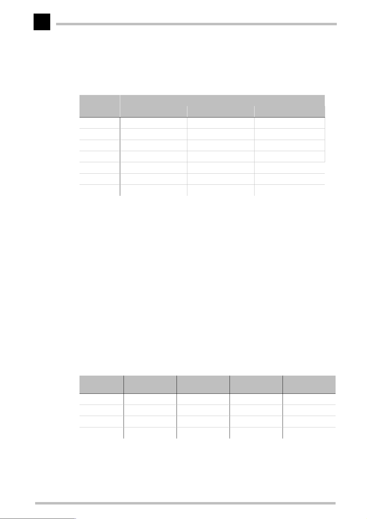
The tables below show the maximum possible resolutions for the ELSA graphics board.
Note that these resolutions cannot be achieved under all operating conditions.
Color depth: 256 colors (8 bit) HighColor (16 bit) TrueColor (32bit)
1900 x 1440 60 – 85 60 – 85 60 – 85
1600 x 1200 60 – 120 60 – 120 60 – 100
1280 x 1024 60 – 170 60 – 170 60 – 150
1152 x 864 60 – 200 60 – 200 60 – 160
1024 x 768 60 – 200 60 – 200 60 – 200
800 x 600 60 – 200 60 – 200 60 – 200
640 x 480 60 – 200 60 – 200 60 – 200
Max. Refresh Rate (Hz)
HighColor = 65,536 colors, TrueColor = 16.7 million colors
What makes sense?
There are some basic ground rules for you to follow when setting up your graphics system. On the one hand, there are the ergonomic guidelines, although nowadays these are
met by most systems, and on the other hand there are limitations inherent to your system, e.g. your monitor. The question of whether your applications need to run using large
color depths––perhaps even TrueColor––is also important. This is an important condition
for many DTP or CAD workstations. We recommend that games and “normal” Windows
applications are operated in HighColor with 65,536 colors.
“More Pixels, more fun”
This is an opinion which is widespread, but which is not entirely true under all circumstances. The general rule is that a refresh rate of 73Hz meets the minimum ergonomic
requirements. The resolution to be selected also depends on the capabilities of your monitor. The table below is a guide to the resolutions you might select:
Monitor
size
17“ 15.5“- 16“ 800 x 600 1024 x 768 1024 x 768
19“ 17.5“- 18.1“ 1024 x 768 1280 x 1024 1152 x 864
20“/21“ 19“- 20“ 1024 x 768 1600 x 1200 1280 x 1024
24“ 21“- 22.5“ 1600 x 1000 1920 x 1200 1600 x 1000
ELSA ERAZOR X and ERAZOR X²
Typical
image size
Minimum
resolution
Maximum
resolution
Ergonomic
resolution
Page 13
After installing the drivers
7
Changing the resolution
You set the resolution of your graphics board in the Control Panel under Windows..
Windows 95 and Windows 98
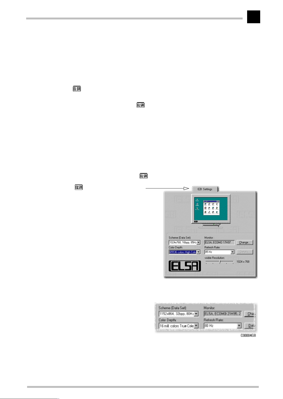
The ' Settings' are automatically integrated into the Control Panel during the installation of the
WINman Suite
for the best performance. The ' Settings' provide some great features. Once you
have specified the graphics board model and the monitor data, the program will automatically detect which settings are possible and which are not. This means, for instance,
that it is impossible for you to select an incorrect refresh rate which might damage your
monitor.
. You can use these Settings to tweak your graphics system
Click on
햲
You will find the
햳
Start
, then select
Display
Settings
Control Panel
왘
.
icon in the Control Panel. When you start this program,
you are shown a dialog box where you can modified the display settings.
Here you should click on the ' Settings' tab.
햴
' Settings' has all the options
for setting up the graphics board
for your monitor.
ELSA ERAZOR X
It is important to carry out the following settings or checks step by step:
the monitor type
쮿
the resolution of the monitor
쮿
image (Scheme, Data Set)
the color depth, and
쮿
the refresh rate.
쮿
ELSA ERAZOR X and ERAZOR X²
Page 14
After installing the drivers
8
Choosing the monitor
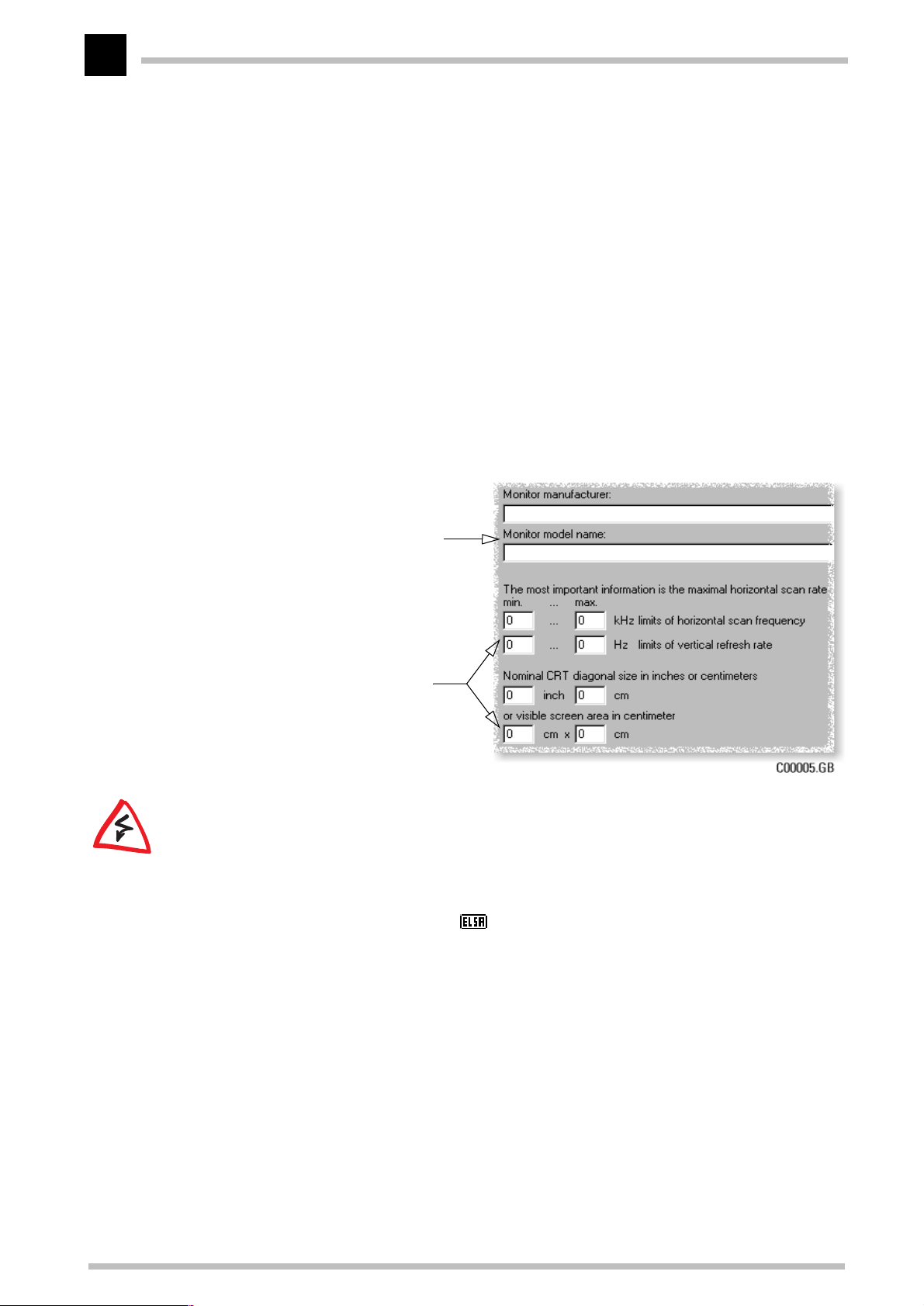
If your monitor supports DDC, the preset values will be displayed under 'Scheme'. If this
is not the case, click on
presented with a list of monitor manufacturers and monitor models. If your manufacturer
is present, click on the entry and then select your model. If your monitor is not listed,
there are two options. One option is to select the '_Standard monitor' from the list of
manufacturers and then select the resolution you wish to work with.
A second option requires information about the technical specifications for your monitor.
Consult your monitor manual to ensure that you have the correct information. Click on
Change...
ing the monitor manufacturer, and the model designation, you will have to enter the frequency ranges for the horizontal and vertical scan frequencies and specify the diagonal
size of your monitor.
Change...
to call up the database of monitor types. You will be
in the 'Monitor type database' window. In addition to the information regard-
If your monitor type is not listed in the
monitors database you can enter the
monitor manufacturer and model type
here.
The vertical and horizontal frequency
ranges and the diagonal size of the
screen are the important settings.
Check your entries for the image frequencies carefully, as otherwise you might damage
.
your monitor
Look these up in your monitor manual or consult the monitor manufacturer.
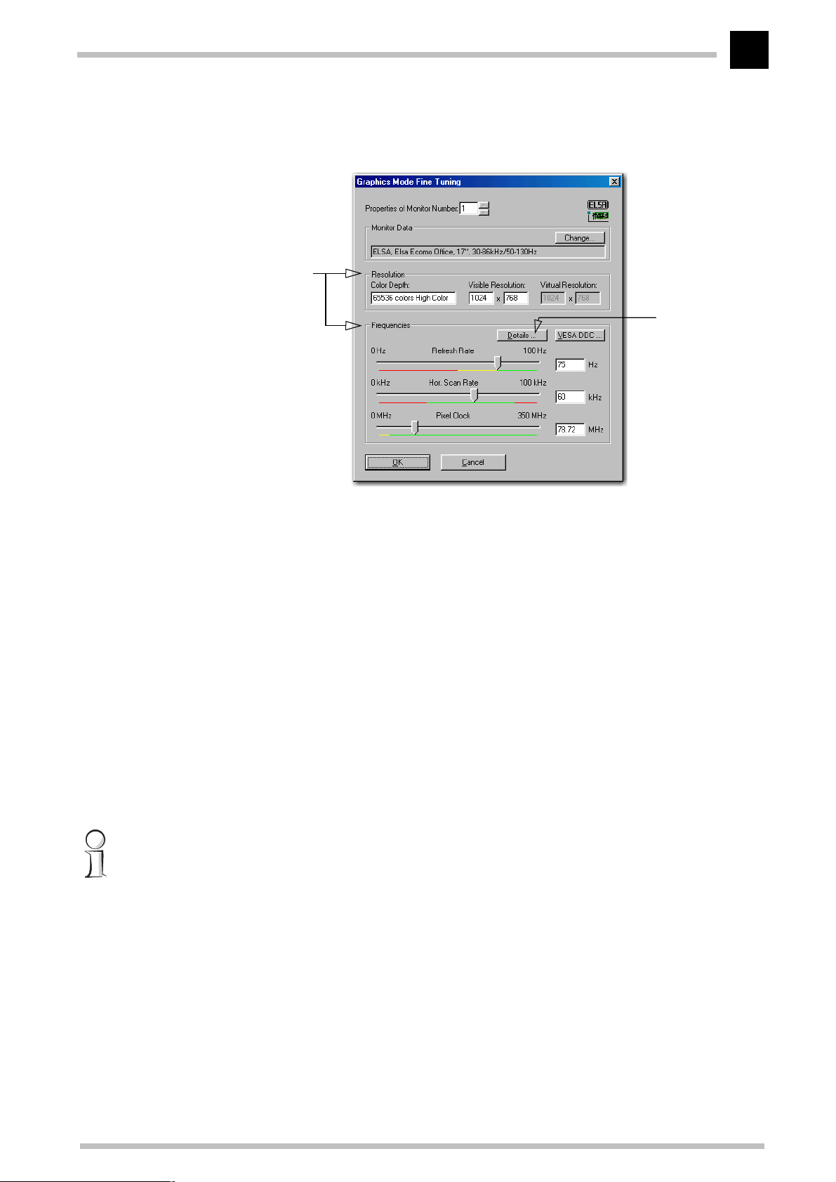
ELSA SmartRefresh and ELSA SmartResolution
Click on the
Details
button in the ' Settings' to open a dialog where you can adjust
the refresh rates and video timings individually. In addition you can change the resolution in steps of 32 pixels. The graphics mode fine-tuning tool is especially for screens in
ELSA ERAZOR X and ERAZOR X²
Page 15
After installing the drivers
9
portrait or wide-angle format, or with the 4:3 aspect ratio. In such cases it is clearly
advantageous to have the option of freely-selectable values.
Free choice:
and refresh rates can be
freely adjusted.
Resolution
Note:
The set-
tings for the moni-
tor timings should
only be changed
by specialists.
Windows NT 4.0
The settings for the graphics driver are included in the Control Panel under Windows NT
4.0. Use the command sequence
Start
to call the dialog window where you should find the icon for
Settings
왘
Control Panel
왘
Display
. Double click on
this symbol to open the window with its various tabs. Click on the 'Settings' tab.
You can select the possible settings for 'Color palette', 'Font size', 'Resolution' and 'Dis-
play frequency' from this dialog box. The available selection is determined by the ELSA
driver you have installed. You should always check the configuration you have selected
by clicking on the
Test
button.
You will find further information on how to customize your graphics settings under Windows NT 4.0 in your system manual.
ELSA ERAZOR X and ERAZOR X²
Page 16

After installing the drivers
10
ELSA ERAZOR X and ERAZOR X²
Page 17
Useful stuff and more
11
Useful stuff and more
Apart from the ELSA drivers, the CD also contains additional programs and utilities for
use with the
here. Information about other programs can be taken from the README files on the CD.
ELSA ERAZOR X and ERAZOR X²
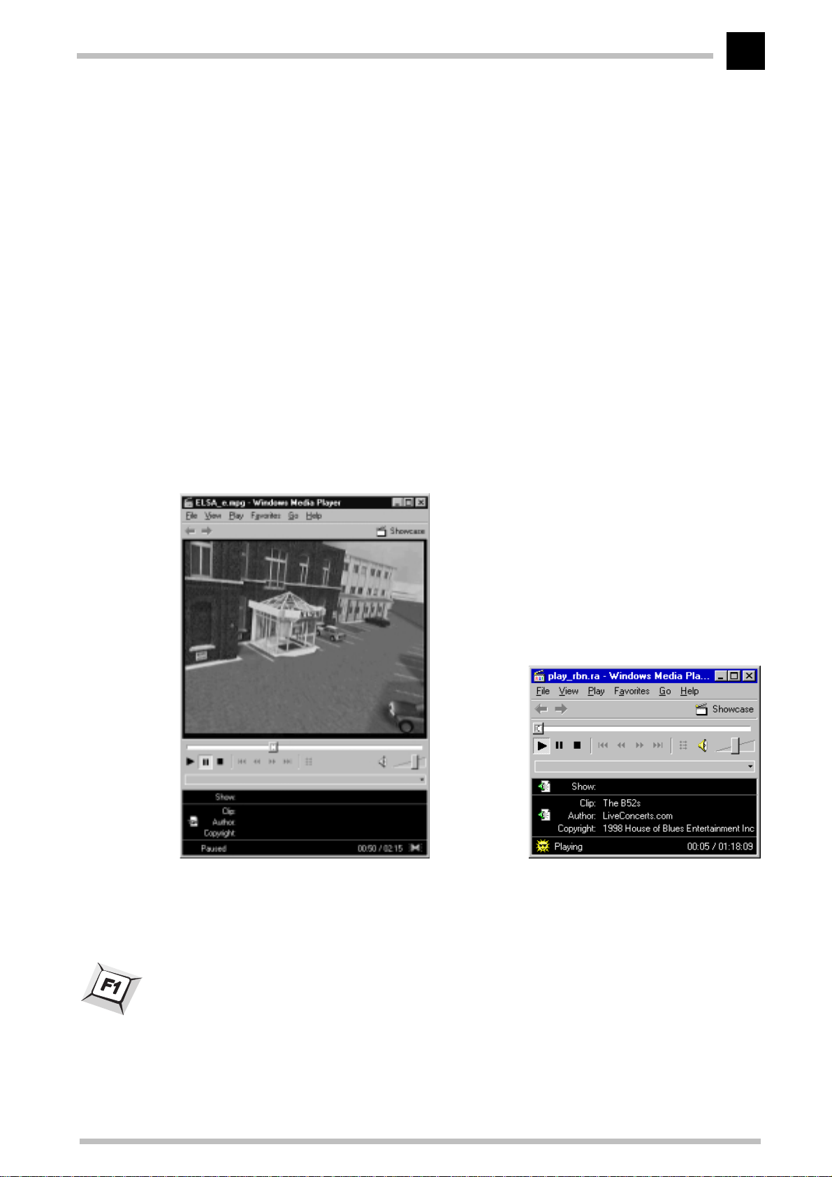
The Multimedia Player
Until now, a variety of programs for the playback of CDs, videos and other media was
available under Multimedia in the Accessories folder of the Windows start menu. These
have now been succeeded by the Microsoft Multimedia Player. It handles the most common multimedia formats, all under one common user interface—regardless of whether
the data is coming from the Internet or the local hard disk. The Multimedia Player is
responsible for the playback of RealAudio and RealVideo, as well as WAV, AVI and
Quicktime files.
, a selection of which we will introduce
Video playback or Internet live radio: The
Microsoft Multimedia Player handles all
common multimedia formats.
After the installation, the file extensions of media files are permanently associated with
the Multimedia Player. You can thus double-click the media files in the Windows
Explorer or My Computer folder to conveniently launch the Player and start the playback.
The use of the Multimedia Player is intuitive, and it includes a comprehensive help function to clarify questions or solve problems while working with the program.
ELSA ERAZOR X and ERAZOR X²
Page 18
Useful stuff and more
12
Fine-tuning for performance freaks
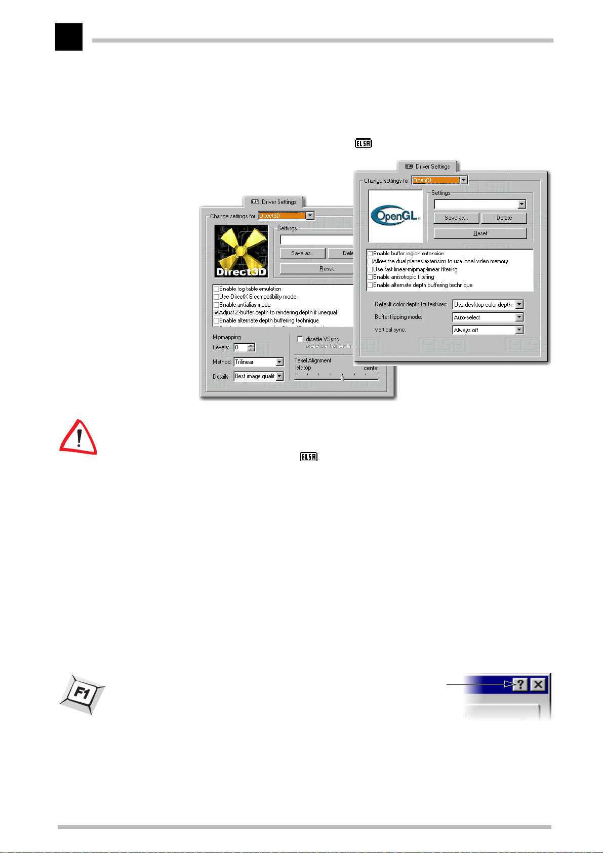
After installing the ELSA graphics drivers under Windows 95 and Windows 98 you will
find a new tab in the 'Display Properties': The ' 3D Settings'
Because Windows 98 allows the operation of multiple graphics boards, the 3D Settings
for the ERAZOR are to be found in another location. Under 'Display Properties' select in
'Settings' 왘
turn:
These settings let you set up the optimal games performance on your system. In most
cases you don’t need to adjust anything. Once in a while if you see display errors on
screen or if there are problems with the speed, you can adjust the driver settings. The
settings which are optimal for any game can saved under an identifiable name and
quickly recalled without having to restart your system.
Experimentation pays! Give your combatant a little extra “zip” and optimize his chances
against the competition. If the descriptions here are too cryptic, just take a look at the
glossary in this manual or use the comprehensive help system. Simply click on the question mark at the top right-hand corner of the dialog window, and then click on the item in
question. If you accidentally dump your system into the crawler-lane, just click on the
emergency button
The question mark provides the answers! If you want more information about any setting, just click on this symbol and then select the area in the dialog about which you want to know more .
Advanced...
Restore Defaults
왘 ' 3D Settings'
.
. The standard settings will be called into action.
ELSA ERAZOR X and ERAZOR X²
Page 19
ELSA ChipGuard
Useful stuff and more
13
ERAZOR X
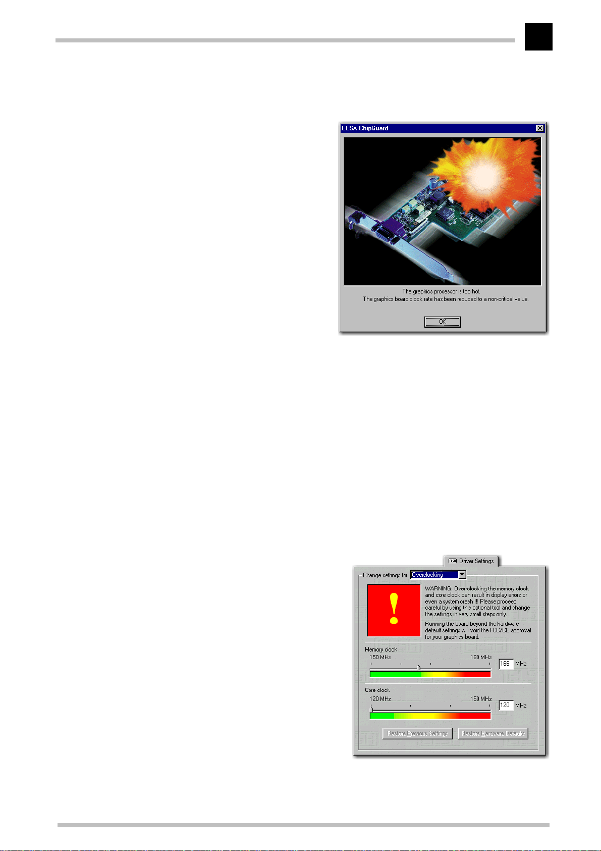
ELSA ChipGuard is your reliable helper
in the background. It is most useful
when you want to use the ELSA ➞overclocking tool to tease more than the
“allowed“ performance out of your
graphics board.
ChipGuard continually monitors the
temperature of the chip during use. As
soon as the temperature exceeds a critical value (approximately 100° Celsius),
the clock rate of the chip and memory is
automatically reduced to a non-critical
value below the default settings. After a
reboot the normal settings are active.
This protects the chip from thermal failure.
ELSA ChipGuard is installed automatically along with the drivers. It is started whenever
Windows ist started. ChipGuard functions fully automatically.
Despite its important role, ELSA's ChipGuard remains in the background. When the hardware is functioning, a green dot is displayed in the start menu. The dot becomes red as
soon as the hardware reaches a critical condition. If the fan is not working properly when
checked at startup, a window opens to notify the user that the fan is either working too
slowly, or not at all.
Overclocking
The overclocking tool enables you to
increase the values for memory clock and
core clock in order to push the performance
of the graphics board
If you like to increase these values please
be careful! In any case you should do it in
little steps (1MHz). Changing the settings
becomes active when you click the button
Accept
.
The first sign when putting great strain on
the graphics board are pixel errors, which
ELSA ERAZOR X and ERAZOR X²
Page 20
Useful stuff and more
14
you can easily notice on your monitor. If the values are too high the ➞ELSA ChipGuard
becomes active.
ELSAinfo
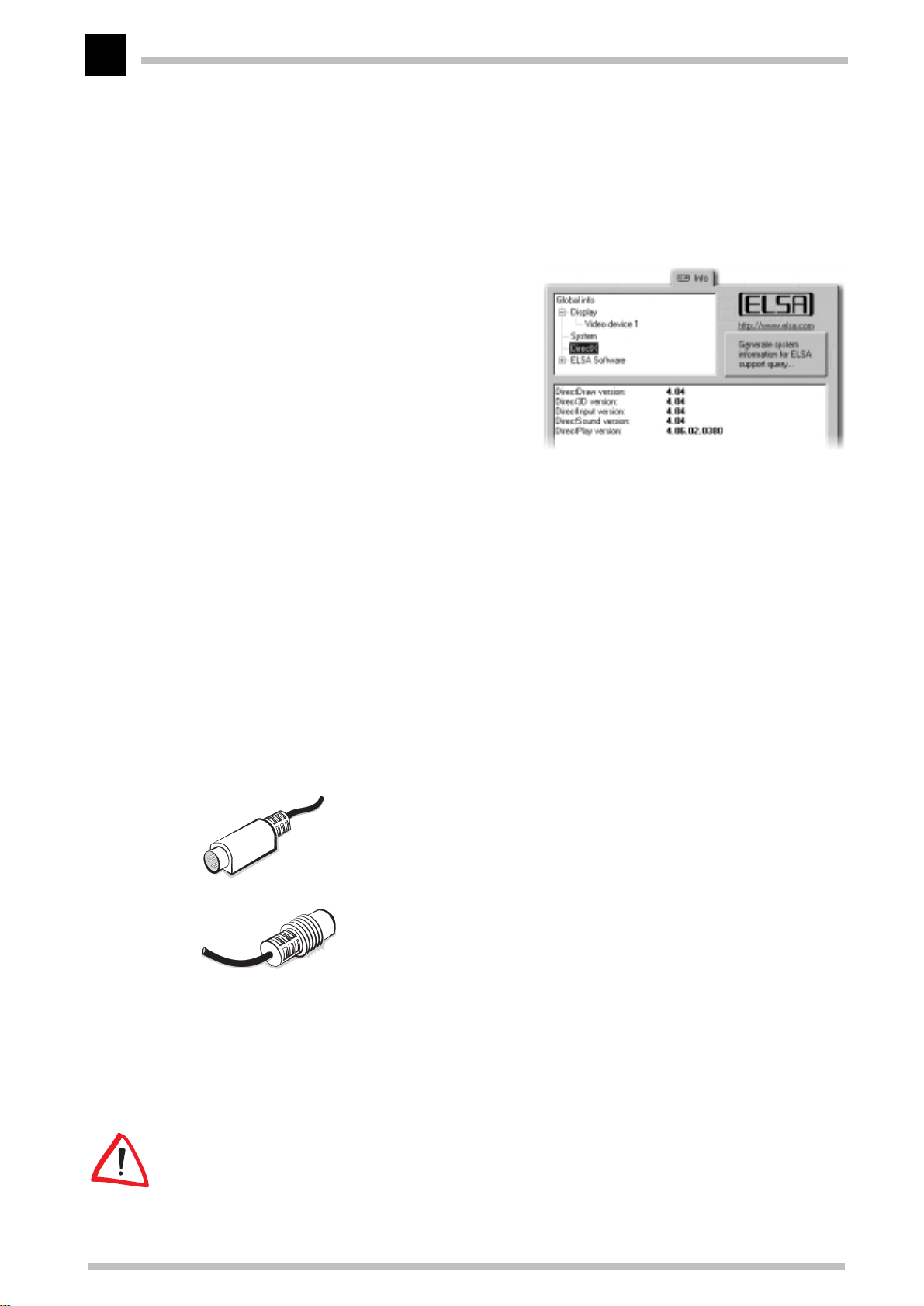
Use
ELSAinfo
In addition to the details about your
graphics board you will find information
about your computer system, the DirectX
and OpenGL driver versions and the ELSA
software you have installed. This information provides a basis for generating a
report that can be of use in case you
require support. This collection of information provides the ELSA Support with all the information they need to guarantee you
fast and relevant help.
Video out with the
to investigate your system.
ELSA ERAZOR X²
Connecting to the Video Outputs
Apart from the VGA socket for connecting your computer’s monitor, the graphics board
features an additional video output socket. You can connect video players or recorders
equipped with an S-Video input or with a Cinch socket (composite input). You can use the
supplied adapter for this. Be sure to check the Connector settings for the Video-Out.
Hosiden plug
Plug for connecting video signal sources and video players or recorders to the
graphics board. Your graphics board is supplied with a special adapter
➞
(Hosiden plug
signals.
Cinch socket
With the adapter’s Hosiden plug connected with the S-Video output of the
graphics board, you can use a Cinch cable from a video player or recorder and
connect this to the Cinch socket on the adapter.
Connection to a TV Set
You can connect any normal TV set to the graphics board. Refer to the operating manual
for your television to find out which video standards it supports, or ask your TV dealer.
You can connect PAL or NTSC devices to the graphics board.
Cinch socket) for supplying composite inputs with S-Video
Some VCRs and TV sets provide only a SCART connector for video input. To connect the
graphics board to the device you will need a SCART-to-S-Video/composite adapter which
ELSA ERAZOR X and ERAZOR X²
Page 21
Useful stuff and more
15
should be switchable between video-in and video-out. Your local TV/video dealer should
be able to provide you with a suitable adapter.
Settings under Windows 9x
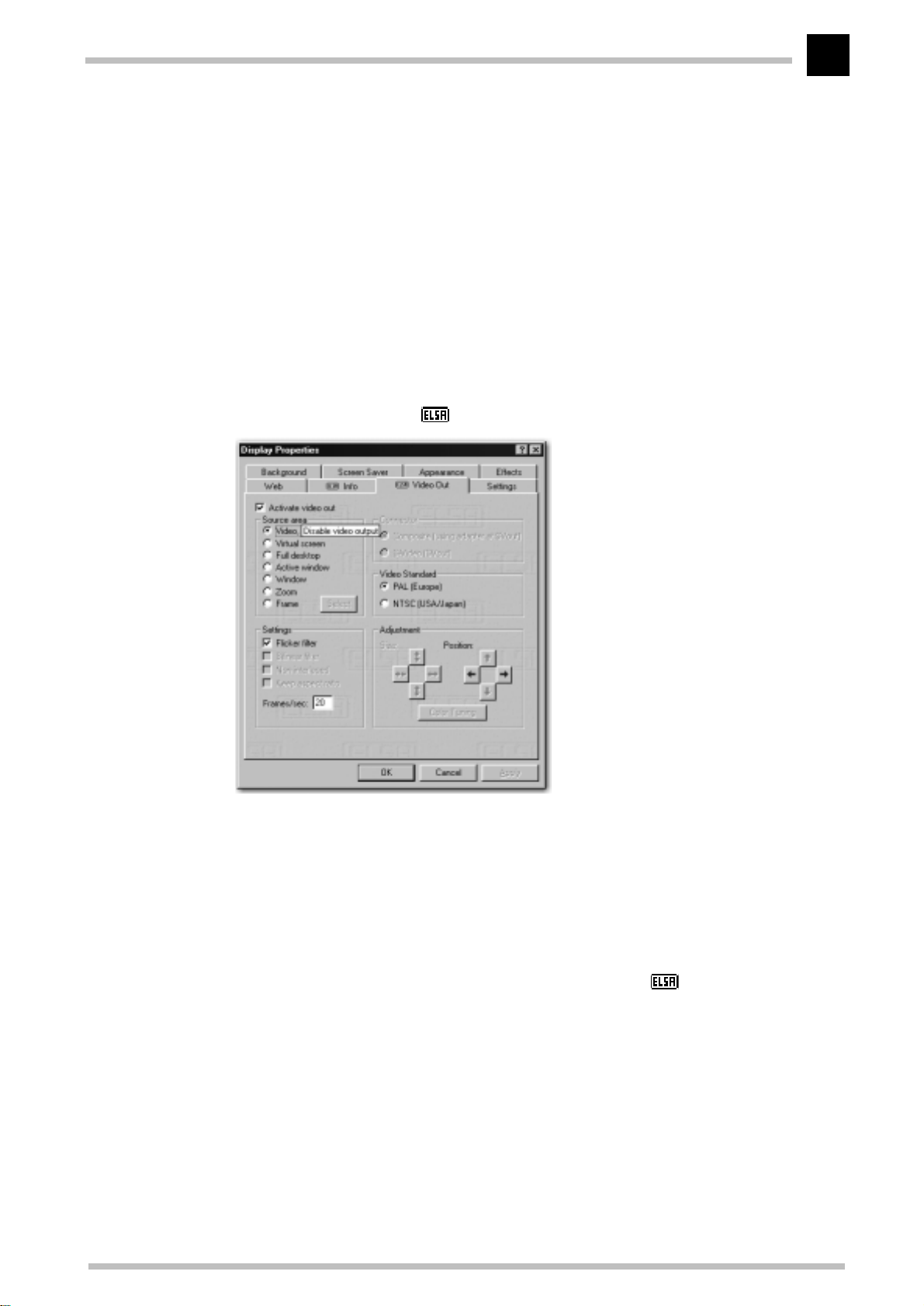
What you see on your computer monitor can also be displayed on video, TV, or via a video
beamer. The entire screen, or even just a part of it; the active window of any application,
for example.
Choose
햲
Start 왘 Settings 왘 Control Panel 왘 Display
to call the dialog for the ' Video Out'.
Next, check if the video output is active.
햳
Now check the video standard. Depending on the standard you require, activate
햴
either PAL or NTSC.
Under 'Connector', select the video input type, be it composite or S-Video.
햵
Should a black and white image appear on your TV, call the Video Out dialog and
click on
the color-carrier frequency until a colorful and stable picture is seen on your TV.
By now, you should see your monitor display on the video device. In the 'Source area''
field you will see several options for the deciding which part of the image should be displayed. Under 'Settings' and 'Adjustment' you can further optimize the quality, size and
position of the on-screen image.
Color Tuning
. In the Color Tuning window, move the slider left or right to adjust
ELSA ERAZOR X and ERAZOR X²
Page 22

Useful stuff and more
16
ELSA ERAZOR X and ERAZOR X²
Page 23
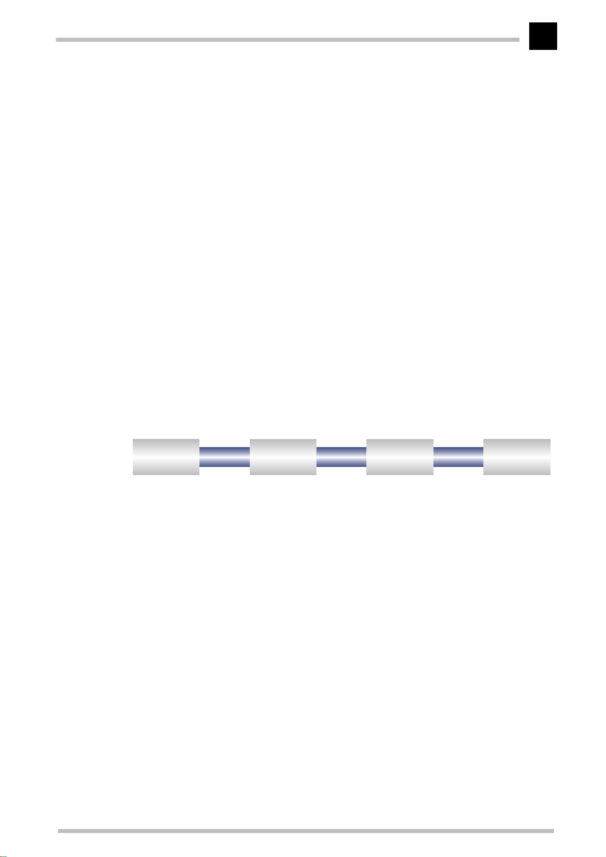
All about graphics
Object data
Geometrical
transformation
Rendering
Display on
the monitor
17
All about graphics
This is the chapter where we really get stuck in. Anyone who wants to know more about
graphics—especially in connection with the
a whole load of technical stuff right here.
ELSA ERAZOR X and ERAZOR X²
3D graphics representation
Today it is considered de rigeur to know all about 3D. Your curiosity will be aroused as
soon as you experience the first visual wizardry generated by your new graphics board.
Two features of the 3D display will leap out at you: it's both realistic and fast. The
amount of work required here is known only to the processor, but we will describe it in
detail to you below.
—will finde
The 3D pipeline
What actually happens when a monitor displays a 3D object? The data describing the 3D
object are passed through what is known as the 3D pipeline, in which the mathematical
calculations for its representation in space and perspective on the monitor are carried
out. What happens in detail?
Start: The object data
The pipeline starts at the object. The object description is made up of the data (points).
Geometrical transformation
This part of the 3D pipeline is very processor-intensive, as all the calculations for the 3D
scene are carried out at this stage. Simplified, it comprises of the following steps:
ELSA ERAZOR X and ERAZOR X²
Page 24

All about graphics
18
Illumination
쮿
Transformation
쮿
from the observer's point of view.
Back face culling
쮿
observation perspective chosen. Any object having an invisible front surface is
omitted.
3D clipping
쮿
partially or fully invisible. The invisible faces or parts of objects will be removed.
Scaling on the screen
쮿
sional space using normalized coordinates. The on-screen image coordinates will
only now be computed.
Rendering
At this stage, the 3D scene is filled with color shades and textures are applied. Different
processes and methods are also applied here.
Texture mapping
쮿
materials and textures are assigned. Different methods are used here to make the
textures appear realistic, even when enlarged or reduced. As a first step, the textures are computed:
– The illumination of the scene by different light sources is calculated.
– In transformation, the objects are aligned in perspective as seen
– This process computes hidden surfaces resulting from the
– In this process, each polygon is checked to determine whether it is
– The above steps are now calculated for three-dimen-
– At this stage, the 3D object undergoes a sort of ”face lift”. The
– Point sampling is the simplest method. A pixel-by-pixel comparison is made
between the texture template and the surface to be filled. This method leads to
a very coarse representation, especially when enlarged.
– In linear mapping, a new color value is interpolated from the adjacent pixels (or
telexes) of a texture. This gives better results than point sampling, as the hard
boundary between the coarse pixels is blurred.
– The MIP mapping method stores a large number of enlargement stages for the
texture. The depth information of a primitive is then used to determine which
enlargement stages of the texture will be used in drawing. Normal textures seldom contain more than 256 colors.
The first 15 bits of a 16-bit wide color representation are reserved for the colors
(5/5/5 > R/G/B). Information concerning the transparency of the texture is carried in the alpha channel. The last bit is reserved for this information. Finally, a
distinction is made in MIP mapping between bilinear and trilinear filtering. Bilinear filtering interpolates between two pixels of two textures, trilinear filtering
interpolates between four pixels for each of two textures.
– Bump mapping introduces a new dimension. Relief or raised textures can only
be generated with the other methods in two dimensions using light and shadow
effects. In bump mapping, the texture is additionally assigned height information, which allows very realistic three-dimensional effects to be created.
ELSA ERAZOR X and ERAZOR X²
Page 25

All about graphics
The staircase effect is corrected by anti-aliasing. This is either done by interpolating
mixed pixels, in which a new color value is computed from two adjacent color values, or by using transparent pixels of the same color which are overlaid over adjacent pixels.
19
Shading
쮿
on the 3D object and provide for a very realistic overall impression. Here, too, there
are different methods which are more or less processor-intensive:
– Flat shading assigns a color value to each polygon. This results in a mosaic-like,
– In Gouraud shading, all the vertices of the polygons are assigned a color value.
– The Phong shading method additionally takes a normal vector of reflectivity into
– Certain applications use ray tracing methods. This is a very computer-intensive
The frame buffer
쮿
The finished image will not be written to the frame buffer until this complex sequence of steps is completed. The frame buffer is made up of front and back buffer.
The back buffer acts as a buffer page, in which the next image to be displayed is
built up. This prevents the process of image drawing being visible. The duplicate
storage method is also known as double buffering.
– Shading takes account of the effects created by different light sources
jagged representation, which demands only a short processing time.
The remaining pixel information for the polygon is interpolated. This method
gives a very gentle color transition, even with fewer polygons than are required
for flat shading.
consideration when interpolating. An even more realistic impression is generated by the representation of reflections and mirror images.
and time-consuming process in which each individual pixel and its reflection in
3D space is calculated.
Flipping: Display on the monitor
The content of the front buffer is displayed on the monitor. When the drawing process
in the back buffer is completed, this image is then passed to the front buffer in a process
known as flipping.
The next image will only ever be displayed once the image drawing process in the back
buffer is completed. This procedure should be repeated at least 20 times a second to give
a smooth representation of 3D scenarios. In this context, we speak of frames per second
(fops), a very important value for 3D applications. A cinema film runs at 24 fps.
3D interfaces
Software interfaces, including 3D interfaces, are known as APIs (Application Program
Interface). The question is what are these interfaces used for, and how do they work.
ELSA ERAZOR X and ERAZOR X²
Page 26

All about graphics
20
In simple terms: They make developers' work easier. The methods by which the various
interfaces function, are comparable: In the past it was necessary to address the various
hardware components directly in programming if you wanted to exploit their capabilities
to the full. The APIs are a kind of translator operating between the hardware and the
software.
The specification of standard definitions was the precondition for the proper function of
these translation routines. These definitions are implemented by the hardware manufacturers during development and optimized for the hardware concerned. Developers can
implement complex procedures relatively easily by using these definitions. They can use
a uniform command set when programming and do not need to know the characteristics
specific to the hardware.
What APIs are available?
There are a good dozen more or less commonly found 3D APIs. However, in recent years,
two formats have established themselves as the favorites: Direct 3D and OpenGL. ELSA
graphics boards support these commonly found 3D interfaces. The functional differences
between the interfaces are slight. The decisive questions for the user concern extensibility, flexibility and possible portability to existing applications.
Direct 3D
As a development of Mode X and DirectDraw under Windows 3.1x, Direct 3D is a branch
of the DirectX multimedia family which was developed directly for Windows 95 to accelerate the slow 3D display characteristics of the operating system. Direct 3D is based on
Microsoft's Common Object Model (COM), which is also used as the foundation to OLE
technology (Object Linking and Embedding). Direct 3D cooperates with Direct Draw in
two-dimensional display. A typical situation would be, for instance, rendering a 3D
object while Direct Draw is placing a two-dimensional background bitmap.
Immediate mode and retained mode
As can be assumed from the two terms, immediate mode is a programming mode that is
close to the hardware. Retained mode, on the other hand, is a programming mode that
is largely predefined through an API interface. What does this mean in detail? Looking
at the two systems hierarchically, the immediate mode is also known as the low-level
mode. The programming interface level is close to the hardware level and permits the
programmer direct access to special functions in the hardware component concerned.
The retained mode (high-level mode) makes it possible, for example, to load a defined 3D
object with textures into a Windows application. Here it can be manipulated and moved
using simple API commands. Translation takes place in real time, without the need to
know the technical structure of the object.
For further information see the Internet WWW site http://www.microsoft.com
ELSA ERAZOR X and ERAZOR X²
Page 27
All about graphics
21
OpenGL
Following its success in gaining a good reputation amongst professionals using CAD/
CAM programs, OpenGL is now increasingly penetrating the PC market. OpenGL is platform-independent and makes a distinction between immediate and display list modes. A
display list stores specific sequences that can be recalled again later. The object descriptions can then be taken directly from the list, resulting in very high performance. However, if objects need to be manipulated frequently, the display list will have to be
generated again from new. In this case, the speed advantage is lost. OpenGL provides
a wide range of graphics features, from rendering a simple geometric point, line, or filled
polygon, to the most sophisticated representations of curved surfaces with lighting and
texture mapping. The some 330 routines of OpenGL provide software developers access
to these graphics capabilities:
For further information see the Internet WWW site http://www.sgi.com
Color palettes, TrueColor and gray scales
Common graphics modes are listed in the following table. Not all graphics modes are
available on the
Graphics mode bpp bpg
VGA 0x12
VGA 0x13
Standard 8
HighColor 15
TrueColor 24
(bpp = bits per pixel; bpg = bits per gun)
ELSA ERAZOR X and ERAZOR X²
4
8
8
16
16
32
6+6+6
6+6+6
6+6+6
6+6+6
5+5+5
6+6+4
5+6+5
8+8+8
8+8+8+8
VGA
boards.
Colors
(from palette)
16 of 262,144
256 of 262,144
256 of 262,144
256 of 16.7 million
32,768
65,536
65,536
16.7 million
16.7 million
Max. gray levels
16
64
64
256
32
16
32
256
256
In VGA graphics adapters, the digital color information stored in the video memory (4 bits
for 16 colors or 8 bits for 256 colors) is converted into a digital 18-bit value in the graphics
adapter in a CLUT (ColorLookUpTable). The 3 x 6 bits are converted separately for R/G/
B (red/green/blue) in the RAMDAC (D/A converter) and transferred to the monitor as analog signals on just three lines (plus sync lines). The original color values are converted
into completely different values by means of a translation table. The value stored in the
video memory is thus not a color value, but only a pointer to a table in which the actual
color value is found. The advantage of this method: Only 8 bits need to be stored for each
ELSA ERAZOR X and ERAZOR X²
Page 28

All about graphics
22
pixel, although the color values are 18 bits wide; the disadvantage: Only 256 colors can
be displayed simultaneously from a palette of 262,144 possible colors.
DirectColor
The situation is different in the case of DirectColor (TrueColor, RealColor and HighColor).
In this case, the value stored in the video memory is not translated but is passed directly
to the D/A converter. This means that the full color information must be saved for each
pixel. The meanings of the terms RealColor, TrueColor, and HighColor can be confused,
as they are not always used unambiguously.
HighColor and RealColor
HighColor and RealColor usually describe a 15 or 16-bit wide graphics mode, while TrueColor should only be used for the more professional 24-bit mode (or 32-bit) mode.
15 bits provide 5 bits each for the red, green and blue values, resulting in 32 levels per
RGB component and thus 32,768 (= 32 x 32 x 32) different color hues.
The 16-bit graphics modes are organized differently. Most common are (R-G-B) 5-6-5
(e.g. XGA) and 6-6-4 (e.g. i860). 5-6-5 means that 5 bits are used for each of red and
blue and 6 bits are used for green. In the case of 6-6-4, 6 bits are used for red and green
and 4 bits for blue. Both ways of assigning the bits correspond to the color sensitivity of
the human eye: this is highest for green and lowest for blue. 65,536 different colors can
be displayed.
TrueColor
The TrueColor mode is more complex, using 24 bits per pixel. Here, 8 bits are available
for each color component (256 levels), resulting in 16.7 million different color hues. There
are more colors available than pixels on the screen (1.3 million pixels at a resolution of
1280 x 1024 ).
VESA DDC (Display Data Channel)
The Display Data Channel provides a serial data channel between the monitor and the
graphics board, as long as both support DDC and the monitor cable includes the additional DDC wire. This feature allows the monitor data to be sent automatically to the
graphics board (e.g. name, type, max. horizontal frequency, timing definitions etc.) or
even for the graphics board to send instruction to the monitor.
There are various standards; DDC2B and DDC2AB.
ELSA ERAZOR X and ERAZOR X²
Page 29
All about graphics
23
DDC2B
A bi-directional data channel based on the I2C access-bus protocol is used for the communication between monitor and graphics board. In the case of a standard IBM VGA
compatible 15-pin monitor connector, pin 12 (formerly used as monitor ID bit 1) is used
for data transmission (SDA), and the pin 15 (formerly used as monitor ID bit 3) is used as
transmission clock (SCL). The graphics board can request the short EDID information (see
DDC1) as well as the more comprehensive VDIF information (VESA Display Identification
File).
DDC2AB
With DDC2AB additional to DDC2B, the computer can send commands for controlling the
monitor, e.g. for adjusting the screen position or the brightness (similar to ACCESS bus).
Modern monitors and graphics boards no longer use this standard.
The pin assignment of the VGA D-shell socket can be found in the chapter 'Technical
data'.
ELSA ERAZOR X and ERAZOR X²
Page 30

All about graphics
24
ELSA ERAZOR X and ERAZOR X²
Page 31
Technical data
Technical data
25
Those with a technical interest will find more detailed information regarding the
ERAZOR X and ERAZOR X²
in this chapter. All interfaces and their assignments are
described in detail.
Characteristics of the graphics board
ERAZOR X²
Graphics processor GeForce by nVidia
RAMDAC pixel timing
On-board memory
BIOS
Bus system
VESA DDC
Graphics processor GeForce by nVidia
350MHz
32MB DDR RAM
Flash BIOS with VBE 3.0 support
AGP, 2x/4x (AGP 4x is only supported by special mainboard chipsets, e.g.
Intel 820, Intel 840 and VIA Apollo Pro133A)
DDC2B
ERAZOR X
ELSA
RAMDAC pixel timing
On-board memory
BIOS
Bus system
VESA DDC
350MHz
32MB SyncRAM with over 1.6Gbps bandwidth
Flash BIOS with VBE 3.0 support
AGP, 2x/4x (AGP 4x is only supported by special mainboard chipsets, e.g.
Intel 820, Intel 840 and VIA Apollo Pro133A)
DDC2B
ELSA graphics board addresses
The ELSA graphics boards are 100% IBM VGA compatible and occupy the same memory
area and specific addresses in the I/O range. The memory range above 1MB is automatically assigned through the PCI BIOS interface.
If you come across any address conflicts, try to modify the I/O address of the expansion
board causing the conflict. The addresses of the ELSA graphics boards cannot be
changed! The ERAZOR X also requires an interrupt (IRQ) which is free. This may have to
be reserved in the computer’s BIOS. For help with this theme, refer to the manual for your
mainboard.
ELSA ERAZOR X and ERAZOR X²
Page 32
Technical data
26
To ensure that your system functions properly, the addresses and ranges occupied by the
ELSA graphics board must not be accessed simultaneously by other hardware components. The following addresses are assigned:
I/O addresses:
쮿
Standard VGA I/O (3B0-3DF)
Memory addresses:
쮿
Video RAM (A0000-BFFFF)
Video BIOS-ROM (C0000-C7FFF)
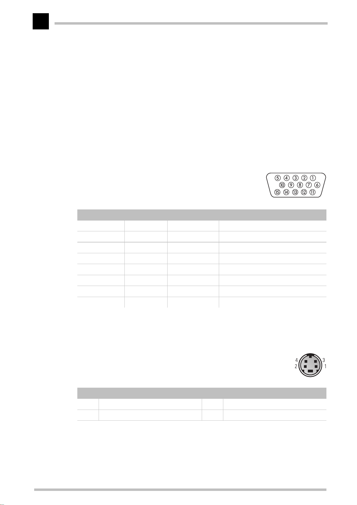
Ports on the graphics board
The VGA D-shell socket
Pin assignment
Connection Signal Connection Signal
1Red 9 +5 V
2 Green 10 Sync ground
3 Blue 11 Monitor ID2
4 Monitor ID0 12 Bidirectional data (SDA, DDC1/2B)
5 DDC ground 13 Horizontal synchronization
6 Red ground 14 Vertical synchronization
7 Green ground 15 Data timing (SCL, DDC2B)
8 Blue ground
ELSA ERAZOR X and ERAZOR X²
The
issues analog signals in accordance with the
requirements of directive RS-170. The synchronization information is sent separately.
The S-Video connector
Pin assignment
Pin Signal Pin Signal
1 GND, ground (Y) 2 GND, ground (C)
3 Y, intensity (luminance) 4 C, color (chrominance)
ELSA ERAZOR X and ERAZOR X²
Page 33
Appendix
Comply
Declarations of conformity
Appendix
27
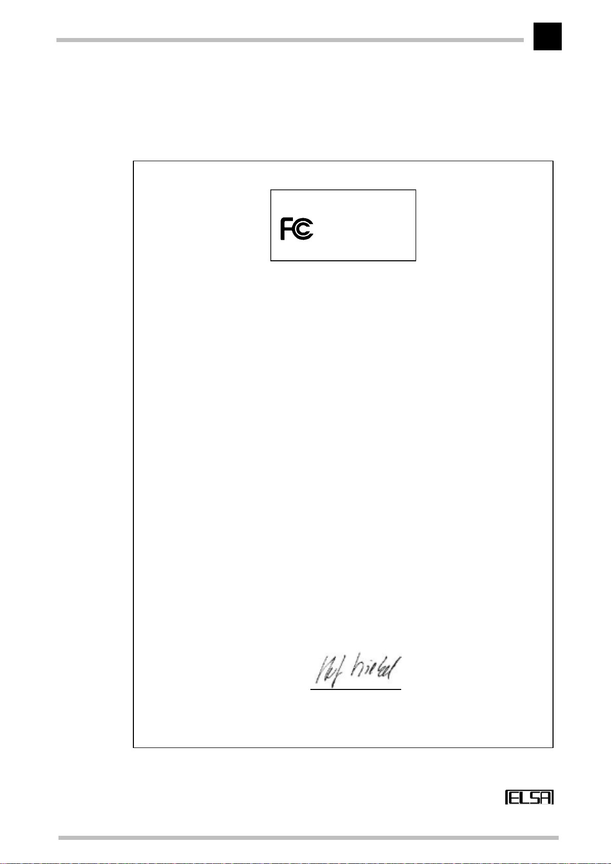
ELSA AG
Tested To
With FCC Standards
FOR HOME OR OFFICE USE
Compliance Information Statement
(Declaration of Conformity Procedure)
Responsible Party: ELSA Inc.
Address: 2231 Calle De Luna
Santa Clara, CA 95054
USA
Phone: +1-408-919-9100
Type of Equipment: Graphics Board
Model Name: ERAZOR X
ERAZOR X
This device complies with Part 15 of the FCC rules.
Operation is subject to the following two conditions:
(1) this device may not cause harmful interference, and
(2) this device must accept any interference received, including interference that may
cause undesired operation.
See user manual instructions if interference to radio reception is suspected.
On behalf of the manufacturer / importer
this declaration is submitted by
Aachen, October 06th 1999
Stefan Kriebel
VP Engineering
ELSA AG, Germany
ELSA ERAZOR X and ERAZOR X²
Page 34
28
Comply
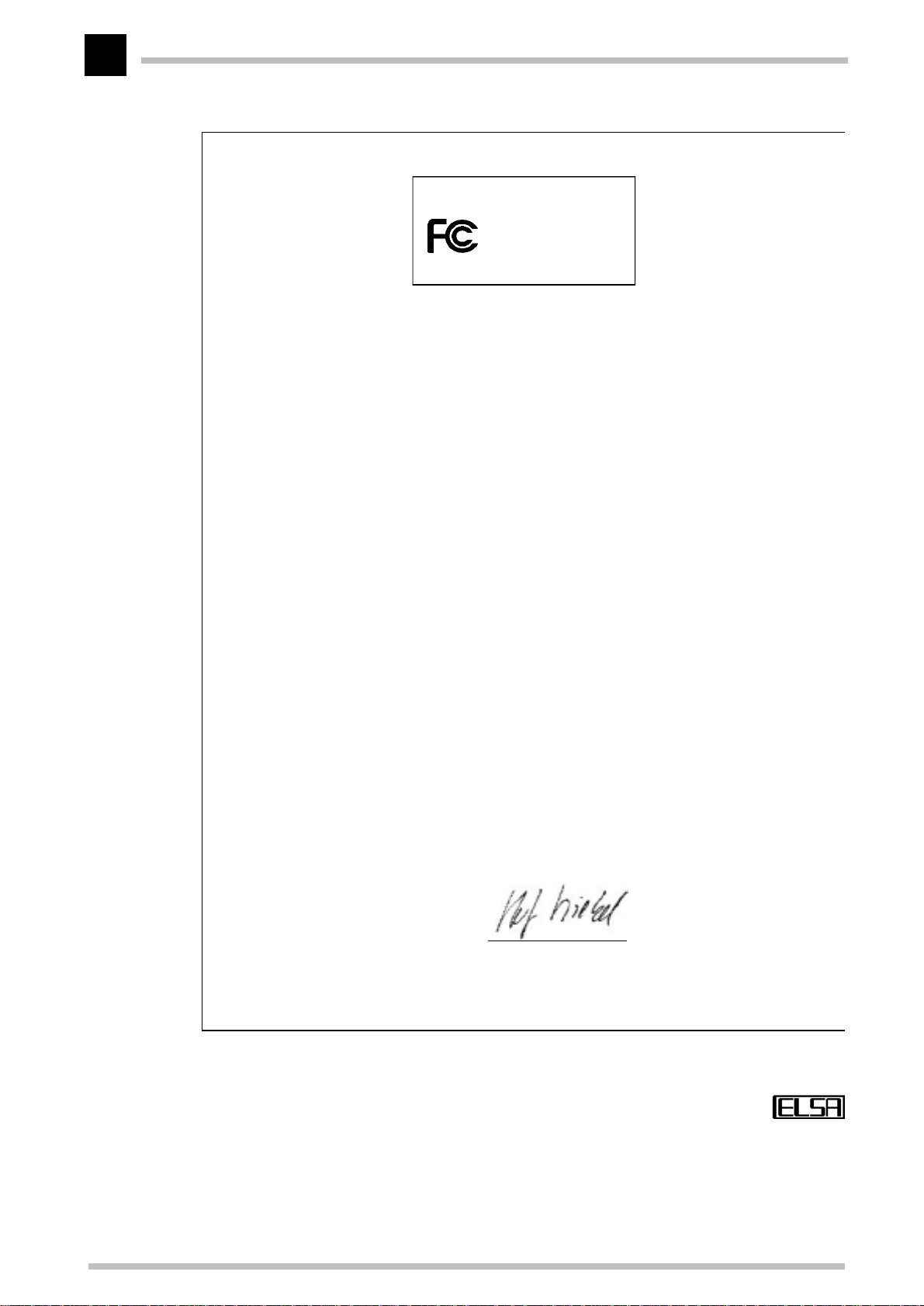
Compliance Information Statement
(Declaration of Conformity Procedure)
Responsible Party: ELSA Inc.
Address: 1630 Zanker Road
San José, CA 95112
USA
Phone: +1-408-961-4600
Type of Equipment: Graphics Board
Model Name: Erazor X²
This device complies with Part 15 of the FCC rules.
Operation is subject to the following two conditions:
(1) this device may not cause harmful interference, and
(2) this device must accept any interference received, including interference that may
cause undesired operation.
See user manual instructions if interference to radio reception is suspected.
On behalf of the manufacturer / importer
this declaration is submitted by
Aachen, November 08th 1999
Stefan Kriebel
VP Engineering
ELSA AG, Germany
Appendix
ELSA AG
FOR HOME OR OFFICE USE
Erazor X²
Tested To
With FCC Standards
ELSA ERAZOR X and ERAZOR X²
Page 35

Appendix
Warranty conditions
The ELSA AG warranty, valid as of June 01, 1998, is given to purchasers of ELSA products in addition to
the warranty conditions provided by law and in accordance with the following conditions:
1 Warranty coverage
a) The warranty covers the equipment delivered and all its parts. Parts will, at our sole discretion, be
replaced or repaired free of charge if, despite proven proper handling and adherence to the operating instructions, these parts became defective due to fabrication and/or material defects. Also we
reserve the right to replace the defective product by a successor product or repay the original purchase price to the buyer in exchange to the defective product. Operating manuals and possibly supplied software are excluded from the warranty.
b) Material and service charges shall be covered by us, but not shipping and handling costs involved
in transport from the buyer to the service station and/or to us.
c) Replaced parts become property of ELSA.
d) ELSA are authorized to carry out technical changes (e.g. firmware updates) beyond repair and re-
placement of defective parts in order to bring the equipment up to the current technical state. This
does not result in any additional charge for the customer. A legal claim to this service does not ex-
ist.
29
2 Warranty period
The warranty period for ELSA products is six years. Excepted from this warranty period are ELSA color
monitors and ELSA videoconferencing systems with a warranty period of 3 years. This period begins at
the day of delivery from the ELSA dealer. Warranty services do not result in an extension of the warranty
period nor do they initiate a new warranty period. The warranty period for installed replacement parts
ends with the warranty period of the device as a whole.
3 Warranty procedure
a) If defects appear during the warranty period, the warranty claims must be made immediately, at
the latest within a period of 7 days.
b) In the case of any externally visible damage arising from transport (e.g. damage to the housing), the
transport company representative and ELSA should be informed immediately. On discovery of dam-
age which is not externally visible, the transport company and ELSA are to be immediately informed
in writing, at the latest within 7 days of delivery.
c) Transport to and from the location where the warranty claim is accepted and/or the repaired device
is exchanged, is at the purchaser's own risk and cost.
d) Warranty claims are only valid if the original purchase receipt is returned with the device.
4 Suspension of the warranty
All warranty claims will be deemed invalid
a) if the device is damaged or destroyed as a result of acts of nature or by environmental influences
(moisture, electric shock, dust, etc.),
b) if the device was stored or operated under conditions not in compliance with the technical specifi-
cations,
ELSA ERAZOR X and ERAZOR X²
Page 36

30
Appendix
c) if the damage occurred due to incorrect handling, especially to non-observance of the system de-
scription and the operating instructions,
d) if the device was opened, repaired or modified by persons not authorized by ELSA,
e) if the device shows any kind of mechanical damage,
f) if in the case of an ELSA Monitor, damage to the cathode ray tube (CRT) has been caused especially
by mechanical load (e.g. from shock to the pitch mask assembly or damage to the glass tube), by
strong magnetic fields near the CRT (colored dots on the screen), or through the permanent display
of an unchanging image (phosphor burnt),
g) if, and in as far as, the luminance of the TFT panel backlighting gradually decreases with time, or
h) if the warranty claim has not been reported in accordance with 3a) or 3b).
5 Operating mistakes
If it becomes apparent that the reported malfunction of the device has been caused by unsuitable software, hardware, installation or operation, ELSA reserves the right to charge the purchaser for the resulting testing costs.
6 Additional regulations
a) The above conditions define the complete scope of ELSA’s legal liability.
b) The warranty gives no entitlement to additional claims, such as any refund in full or in part. Com-
pensation claims, regardless of the legal basis, are excluded. This does not apply if e.g. injury to
persons or damage to private property are specifically covered by the product liability law, or in cas-
es of intentional act or culpable negligence.
c) Claims for compensation of lost profits, indirect or consequential detriments, are excluded.
d) ELSA is not liable for lost data or retrieval of lost data in cases of slight and ordinary negligence.
e) In the case that the intentional or culpable negligence of ELSA employees has caused a loss of data,
ELSA will be liable for those costs typical to the recovery of data where periodic security data back-
ups have been made.
f) The warranty is valid only for the first purchaser and is not transferable.
g) The court of jurisdiction is located in Aachen, Germany in the case that the purchaser is a merchant.
If the purchaser does not have a court of jurisdiction in the Federal Republic of Germany or if he
moves his domicile out of Germany after conclusion of the contract, ELSA’s court of jurisdiction ap-
plies. This is also applicable if the purchaser's domicile is not known at the time of institution of
proceedings.
h) The law of the Federal Republic of Germany is applicable. The UN commercial law does not apply
to dealings between ELSA and the purchaser.
ELSA ERAZOR X and ERAZOR X²
Page 37

Glossary
3D –
쮿
쮿
쮿
쮿
쮿
쮿
쮿
쮿
쮿
쮿
Three-dimensional
3D clipping –
formation in which invisible surfaces or parts of
a 3D object are removed.
3D pipeline –
representation of virtual 3D scene on the monitor. These include ➞tesselation, ➞geometrical transformation and ➞rendering.
AGP –
and is a further development by INTEL based on
the PCI bus. The AGP bus provides a greater
bandwidth for data transmission and communicates directly with main memory. The bus is
primarily intended for 3D graphics boards.
Aliasing –
Jagged transitions are often formed between
adjacent pixels in the representation of diagonals or curves. These "jaggies" can be
smoothed out by anti-aliasing.
Alpha blending –
each pixel for creating transparent materials.
Back buffer –
region built up in the background in the frame
buffer during ➞double buffering.
Back face culling –
late the hidden faces of a 3D object.
BIOS –
System. A program code in the read-only memory (ROM) of a computer which performs the
self-test and several other functions during system startup.
Bump mapping –
are assigned depth information which allows
the display of relief or raised structures.
stands for Accelerated Graphics Port
Abbreviation of Basic Input/Output
Process in geometric trans-
Sum of all steps required for the
the familiar "staircase effect".
Additional information for
is the name for the image
Method used to calcu-
Process by which textures
Glossary
Bus system –
쮿
for the transfer of information between individual system components, especially to
expansion boards (e.g. PCI bus).
Chrominance –
쮿
signal.
Clipping –
쮿
representation are determined in clipping.
These parts are then not displayed.
D/A converter –
쮿
signal converter which converts a digital input
signal to an analog output signal.
DCC –
쮿
computer-based production of professional
visualizations and animations for the field of
digital media and the entertainment industry.
DDC –
쮿
special data channel through which a DDCcapable monitor can send its technical data to
the graphics board.
DirectColor –
쮿
RealColor and HighColor. The value that is
stored in the video RAM is not translated but
transferred directly to the D/A converter. This
means that the full color information must be
saved for each pixel.
Double buffering –
쮿
two display buffers. This means that the next
image can be drawn in the page of the display
buffer, which is initially invisible. This image
will be displayed once it is ready and the next
image will be prepared in the other page of the
buffer. Animations and games can be made to
look more realistic with this technique than
with simple single buffer.
(Digital Content Creation) DCC is the
stands for Display Data Channel. A
A system of parallel data lines
Color information in the video
parts of polygons invisible to the
Digital/Analog converter: A
Generic term for TrueColor,
means that there are
31
ELSA ERAZOR X and ERAZOR X²
Page 38

Glossary
32
DPMS –
쮿
Management Signaling. This standard allows
an energy-saving operation of monitors in several steps. The graphics boards described in
this manual support VESA DPMS.
DRAM –
쮿
Access Memory. Volatile memory for read and
write operations.
EDO-RAM –
쮿
Output Random Access Memory (Hyper Page
Mode). EDO-RAM is very common on graphics
boards, as the most recently used data persist
in memory. A number of read accesses to similar data occur during the generation of an
image, so that use of EDO-RAM gives a significant speed advantage.
FCC –
쮿
has been tested and found to comply with the
limits for a Class B digital device pursuant to
Part 15 of the FCC Rules, designed to provide
reasonable protection against harmful interference in a residential installation.
Abbreviation of VESA Display Power
Abbreviation of Dynamic Random
Abbreviation for Extended Data
FCC compliance means that a device
Geometrical transformation –
쮿
of the object in space is determined from the
observer's point of view.
Gouraud shading –
쮿
Graphics accelerator –
쮿
accelerator board, i.e a board particularly
suited for graphics intensive user environments.
HighColor –
쮿
(bits per pixel) graphics mode, i. e. 32,768 or
65,536 colors.
Horizontal frequency –
쮿
quency (scan frequency) of a monitor in kHz.
This value must be set in accordance with the
operating limits of the monitor, otherwise the
monitor might be damaged in extreme cases.
Horizontal scan frequency –
쮿
scan frequency of a monitor in kHz. This value
must be set in accordance with the operating
limits of the monitor, otherwise the monitor
might be damaged in extreme cases.
designates a 15-bpp or 16-bpp
'Shading'.
➞
The horizontal fre-
The position
refers to a graphics
The horizontal
FIFO method –
쮿
used in batch processing and queues in which
the first signal to arrive is processed first.
Fixed-frequency monitor –
쮿
can only be operated at a specific resolution
and refresh rate.
Flat shading –
쮿
Flipping –
쮿
buffer is displayed.
Frame buffer –
쮿
which the image next to be displayed on the
screen is generated. In addition, transparency
effects are calculated in the frame buffer.
Front buffer –
쮿
image page in ➞double buffering.
(first in, first out) a system
A monitor that
'Shading'.
➞
The image generated in the ➞back
Part of the graphics memory in
is the name for the visible
Interpolation –
쮿
stretched or shrunk in order to fit into the display window. If pixels are simply multiplied (for
example, a block of four equally colored pixels
represents the original pixel), aliasing effects
("blocks" and "stairs") will occur. This can be
avoided by interpolation procedures (using
average colors for inserted pixels). Horizontal
interpolation is relatively easy to perform, since
the pixels are drawn to the screen in lines.
Vertical interpolation is more difficult and
requires a complete pixel line to be buffered.
MIP mapping –
쮿
textures are assigned to an object depending
on distance. The representation of the object
becomes more detailed as the observer
approaches the object.
A video image must be
In MIP mapping a number of
ELSA ERAZOR X and ERAZOR X²
Page 39

Glossary
33
Multifrequency/Multisync monitor –
쮿
monitor that can be operated at various horizontal scan frequencies, or that automatically
adapts itself to different video signals (resolutions).
OpenGL –
쮿
E.g. implemented in Windows NT and available for Windows 95. Based on Iris GL from Silicon Graphics and licensed from Microsoft.
Page Flipping –
쮿
back buffer is displayed
➞
PCI bus –
쮿
nent Interconnect Bus. An advanced bus system, i.e. a system of parallel data lines to
transfer information between individual system
components, especially to expansion boards.
Phong shading –
쮿
Pixel –
쮿
Pixel frequency –
쮿
(number of pixels drawn per second in MHz).
Primitive –
쮿
object, such as a triangle. 3D landscapes are
generally broken down into triangles.
RAM –
쮿
ory. Chip memory of a computer or expansion
board that can be read from and written to
(unlike ROM = Read Only Memory).
RAMDAC –
쮿
signals to analog signals on a graphics board.
VGA monitors are only capable of processing
analog signals.
RealColor –
쮿
15-bpp or 16-bpp (bits per pixel) graphics mode,
i.e. 32,768 or 65,536 colors).
Refresh rate –
쮿
Hz) indicates how many times per second an
image on the monitor is refreshed.
3D software interface (3D API).
The image generated in the
Abbreviation of Peripheral Compo-
'Shading'.
➞
Picture element. Dot in the image.
Pixel clock frequency
Simple, polygonal geometrical
Abbreviation of Random Access Mem-
The RAMDAC converts the digital
RealColor normally designates a
or image refresh frequency (in
A
Rendering –
쮿
sentation of a 3D scene, in which the position
and color of each point in space is determined.
The depth information is held in the ➞Z buffer,
the color and size information is held in the
frame buffer.
➞
Resolution –
쮿
tal and vertical direction on the screen, for
example 640 horizontal by 480 vertical pixels
(640 x 480).
RGB –
쮿
Green/Blue color format.
ROM –
쮿
Semiconductor memory that can only be read
and not written to.
S-Video
쮿
video information, where the signals for
chrominance and ➞luminance are sepa-
➞
rated. This results in a higher picture quality.
Shading –
쮿
define the colors on curved surfaces in order to
give an object a natural appearance. To
achieve this, the surfaces are subdivided into
many small triangles. The three most important 3D shading methods differ in the algorithm
used to apply colors to these triangles:
Flat shading: the triangles are uniformly colored.
Gouraud shading: The color shades on a triangle are calculated by interpolating the vertex
colors, resulting in a smooth appearance of the
surface.
Phong shading: the color shades on a triangle
are calculated by interpolating the normal vector.
Shutter glasses –
쮿
scopic LCD projection of 3D scenery to give the
observer a strong impression of space.
Process for calculating the repre-
The number of pixels in horizon-
Color information is saved in the Red/
Abbreviation of Read Only Memory.
–
or S-VHS. Signal transmission of
Shading or rendering is a way to
Goggles which use stereo-
ELSA ERAZOR X and ERAZOR X²
Page 40

Glossary
34
Single buffer –
쮿
ering, where the image buffer is duplicated, the
single buffering mode is not able to access the
next image, which has already been calculated.
This means that animations will run jerkily.
Tearing –
쮿
buffering between the front buffer and the back
buffer. The image change between the front
buffer and the back buffer is synchronized in
tearing.
Tesselation –
쮿
are divided up into polygons (triangles) in tesselation. The vertices, color and, if required,
transparency values, are determined for the triangles.
Textures –
쮿
object, including perspective correction, for
example wallpaper on a wall or a wood texture
By contrast with double buff-
A distinction is made in double
The objects for 3D calculations
Wrapping a bitmap around an
on furniture. Even a video can be used as a texture map.
TrueColor –
쮿
colors (24 or 32 bits per pixel). In this mode, the
color information saved in the display memory
is not translated by a look-up table, but passed
directly to the D/A converter. This means that
the full color information must be saved for
each pixel.
VESA –
쮿
Standards Association. A consortium for the
standardization of computer graphics.
VRAM –
쮿
ory chip for fast graphics boards.
Z buffer –
쮿
the third dimension) for each pixel.
Graphics mode with 16.7 million
Abbreviation of Video Electronics
Abbreviation for video RAM. Mem-
3D depth information (position in
ELSA ERAZOR X and ERAZOR X²
Page 41

Index
Index
35
!
쮿
.............................................. 18, 31
3D clipping
3D pipeline
3D Settings
A
쮿
Addresses
AGP
Aliasing
Alpha blending
Anti aliasing
................................................................ 19
API
B
쮿
Back buffer
Back face culling
BIOS
Bump mapping
.......................................................... 25, 31
Bus
C
쮿
Chrominance
Clipping
Color palettes
Color Tuning
COM
D
쮿
D socket
DDC
............................................. 17, 31
................................................... 12
..................................................... 25
............................................................... 31
......................................................... 31
............................................. 31
................................................. 19
............................................. 19, 31
........................................................ 25, 31
........................................ 18, 31
................................................. 31
......................................................... 31
............................................... 21
................................................. 15
.............................................................. 20
........................................................ 26
............................................................... 31
Declaration of Conformity
....................................................... 21
Direct 3D
DirectColor
DirectDraw
DirectX
DMA
Double buffer
DPMS
DRAM
Driver versions
.............................................. 22, 31
................................................... 20
.......................................................... 14
............................................................. 25
................................................ 31
............................................................ 32
........................................................... 32
.............................................. 14
.......................................... 18
............................ 27
E
쮿
..................................................... 32
EDO-RAM
F
쮿
FCC
Filtering
Flat shading
Flipping
Frame buffer
Front buffer
G
쮿
............................................................ 2, 32
......................................................... 18
...................................... 19, 32, 33
................................................... 19, 32
........................................... 19, 32
............................................. 19, 32
Geometrical transformation
Gouraud shading
Grey scales
H
쮿
.................................... 19, 33
................................................... 21
Hardware description
................................................ 22, 32
HighColor
Horizontal frequency
I
쮿
................................................... 25
I/O address
Immediate mode
Interpolation
Interrupt
................................................................ 25
IRQ
M
쮿
Memory
Memory addresses
MIP mapping
Mode X
Monitor
O
쮿
................................................................ 20
OLE
OpenGL
P
쮿
Page flipping
PCI bus
Performance
........................................... 20
................................................. 32
........................................................ 25
........................................................ 25
.......................................... 18, 32
......................................................... 20
........................................................... 8
............................................. 14, 21, 33
................................................. 33
.......................................................... 33
................................................. 12
................... 17, 32
................................... 25
.................................... 32
................................. 25, 26
ELSA ERAZOR X and ERAZOR X²
Page 42

36
Index
Phong shading ........................................ 19, 33
Pin assignment
Point sampling
.................................................. 18, 33
Primitive
Products supplied
R
쮿
RAMDAC
Ray tracing
RealColor
Refresh rate
Rendering
Resolution
Retained mode
S
쮿
Scan frequency
Shading
................................................... 19, 33
Shutter glasses
............................................. 26
.............................................. 18
........................................... 2
................................................ 25, 33
.................................................... 19
................................................ 22, 33
.................................................. 33
............................................... 18, 33
..................................................... 33
............................................. 20
............................................. 32
............................................. 33
Single buffer
S-Video
T
쮿
Tearing
......................................................... 33
.......................................................... 34
Tesselation
Texture
.......................................................... 34
Texture mapping
Transformation
TrueColor
V
쮿
............................................................. 34
VESA
VESA DDC
............................................................... 21
VGA
VRAM
Z
쮿
Z buffer
........................................................... 34
......................................................... 34
................................................. 34
................................................... 34
........................................... 18
............................................. 18
.......................................... 21, 22, 34
..................................................... 25
ELSA ERAZOR X and ERAZOR X²
 Loading...