

Page 1

M
ELSA MicroLink
TM
Cable
Manual
Page 2

© 1999 ELSA AG, Aachen (Germany)
While the information in this manual has been compiled with great care, it may not be deemed an
assurance of product characteristics. ELSA shall be liable only to the degree specified in the terms of
sale and delivery.
The reproduction and distribution of the documentation and software supplied with this product and the
use of its contents is subject to written authorization from ELSA. We reserve the right to make any
alterations that arise as the result of technical development.
ELSA is DIN EN ISO 9001 certified. The accredited TÜV CERT certification authority has confirmed ELSA
conformity to the worldwide ISO 9001 standard in certificate number 09 100 5069, issued on June 15,
1998.
Trademarks
Windows
®
, Windows NT® and Microsoft® are registered trademarks of Microsoft, Corp.
All other names mentioned may be trademarks or registered trademarks of their respective owners. The
ELSA logo is a registered trademark of ELSA AG.
Subject to change without notice. No liability for technical errors or omissions.
ELSA AG
Sonnenweg 11
52070 Aachen
Germany
ELSA, Inc.
2231 Calle De Luna
Santa Clara, CA 95054
USA
www.elsa.com
Aachen, October 1999
No. 20840/1099
Page 3

Preface
Thank you for placing your trust in this ELSA product.
With the
Internet for you with unparalleled speeds and remain online permanently.
The highest quality standards in manufacturing and stringent quality control are the basis
for high product standards and consistent product quality.
This documentation contains the following chapters:
K Introducing the
K Installation and configuration
K Configuration modes
K Operating modes and functions
K Technical basics
K Technical reference
K Appendix
ELSA MicroLink Cable
ELSA MicroLink Cable
, you have chosen a modem that will open the door to the
Our online services (Internet server www.elsa.com) are available to you around the clock
should you have any queries regarding the topics discussed in this manual or require any
further support. In the Support file section under 'Know-How', you can find answers to
frequently asked questions (FAQs). The KnowledgeBase also contains a large pool of
information. Current drivers, firmware, tools and manuals can be downloaded at any
time.
The KnowledgeBase can also be found on the CD. Just open the file
\Misc\Support\MISC\ELSASIDE\index.htm.
Page 4

Page 5

Content
Content
V
Introducing the
The
ELSA MicroLink Cable
What does the unit look like?............................................................................ 1
Node or hub?...................................................................................................... 3
The highlights of the
Fast Internet....................................................................................................... 4
Internet at all times—always online ................................................................ 5
More than just Internet...................................................................................... 5
CE conformity and FCC radiation standard............................................................. 7
Installation and Configuration ....................................................................................9
First Steps............................................................................................................. 10
Quick Start: Quick configurations......................................................................... 11
Preparations..................................................................................................... 11
Configuration as a bridge ................................................................................ 11
Configuration as a router................................................................................. 13
Set up the workstation computers (Windows 95 or 98)....................................... 15
ELSA MicroLink Cable
takes the stage............................................................ 1
ELSA MicroLink Cable
..................................................................... 1
.......................................................... 4
English
Configuration modes ..................................................................................................17
The user-friendly method: inband......................................................................... 17
Requirements for inband configuration........................................................... 17
Alternatively: addresses can be managed by the DHCP server...................... 17
Starting inband configuration using
Start up inband configuration using telnet...................................................... 18
Configuration commands ..................................................................................... 19
What's happening on the line?............................................................................. 21
Trace Outputs................................................................................................... 21
New firmware with FirmSafe............................................................................... 22
This is how FirmSafe works............................................................................. 22
How to load new software.............................................................................. 23
Configuration using SNMP.............................................................................. 24
General............................................................................................................. 24
Accessing tables and parameters using SNMP.............................................. 25
The Management Information Base (MIB)...................................................... 27
Operating modes and functions ...............................................................................29
Security for your configuration............................................................................. 29
Password protection........................................................................................ 29
Login barring.................................................................................................... 29
Access control via TCP/IP................................................................................ 30
ELSA LANconfig
..................................... 18
ELSA Cable Modem
Page 6

English
VI
Content
Security for your LAN............................................................................................ 30
Encryption ........................................................................................................ 31
TCP/IP packet filters ........................................................................................ 31
The hiding place—IP masquerading (NAT, PAT) ............................................ 31
IP routing............................................................................................................... 32
The IP routing table.......................................................................................... 32
Dynamic routing with IP RIP ............................................................................ 34
Local routing .................................................................................................... 35
IP masquerading (NAT, PAT)............................................................................ 36
DNS forwarding............................................................................................... 38
Bridging............................................................................................................ 39
Automatic address administration with DHCP..................................................... 40
The DHCP client............................................................................................... 41
The DHCP server.............................................................................................. 41
DHCP – 'on', 'off' or 'auto'?.............................................................................. 42
How are the addresses assigned?................................................................... 42
Technical basics .........................................................................................................47
Cable modem technology..................................................................................... 47
Standards......................................................................................................... 47
Access.............................................................................................................. 47
Registration in the cable network ................................................................... 48
Network technology.............................................................................................. 50
The network and its components .................................................................... 50
Connection modes ........................................................................................... 50
Kinds of networks............................................................................................ 52
IP addressing......................................................................................................... 52
IP routing and hierarchical IP addressing........................................................ 55
Expansion through local networks................................................................... 57
Appendix .......................................................................................................................63
Technical data ...................................................................................................... 63
Warranty conditions............................................................................................. 65
Declaration of conformity..................................................................................... 67
Description of the menu options ..............................................................................73
Status.................................................................................................................... 75
Status/Operating-time..................................................................................... 76
Status/Current-time......................................................................................... 76
Status/cable-statistics..................................................................................... 76
Status/LAN-statistics ...................................................................................... 77
Status/bridge statistics ................................................................................... 78
Status/TCP-IP-statistics................................................................................... 79
ELSA Cable Modem
Page 7

Content
Status/IP-router-statistics ............................................................................... 83
Status/config statistics.................................................................................... 85
Status/Queue-statistics................................................................................... 85
Status/MCNS-statistics................................................................................... 87
Status/Init-status............................................................................................. 87
Status/DHCP-client-statistics.......................................................................... 88
Setup..................................................................................................................... 88
Setup/cable-module ........................................................................................ 89
Setup/LAN-module.......................................................................................... 89
Setup/bridge-module....................................................................................... 90
Setup/TCP-IP-module....................................................................................... 91
Setup/IP-router-module................................................................................... 94
Setup/SNMP-module..................................................................................... 101
Setup/DHCP-server-module........................................................................... 101
Setup/Config-module..................................................................................... 103
Firmware............................................................................................................. 104
Other................................................................................................................... 106
VII
English
ELSA Cable Modem
Page 8

English
VIII
Content
ELSA Cable Modem
Page 9
Introducing the ELSA MicroLink Cable
1
Introducing the
Internet access is the main application for the
cable network to which you have connected your modem may offer additional services or
regional information.
This chapter describes the display elements and connections of the modem, accessing
the Internet, and the characteristics and techniques that ensure fast, secure data
exchange.
The precise use of the
sections and with the aid of the examples in the 'Workshop'.
The term 'router', as used in the remainder of the manual, refers to the router functions
of our ELSA MicroLink Cable
The
This section introduces the unit's hardware. It covers the unit's display elements and
connection options.
ELSA MicroLink Cable
ELSA MicroLink Cable
.
ELSA MicroLink Cable
ELSA MicroLink Cable
's features will be explained in the following
takes the stage
. The operator of the
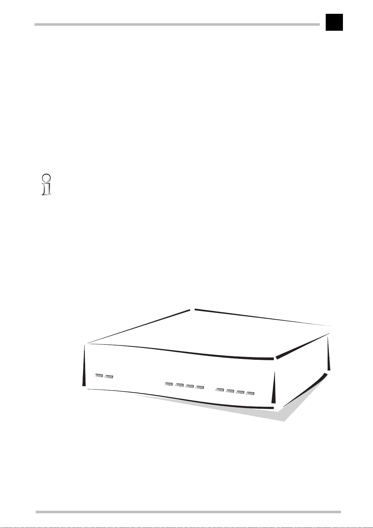
What does the unit look like?
We would first like to familiarize you with the device.
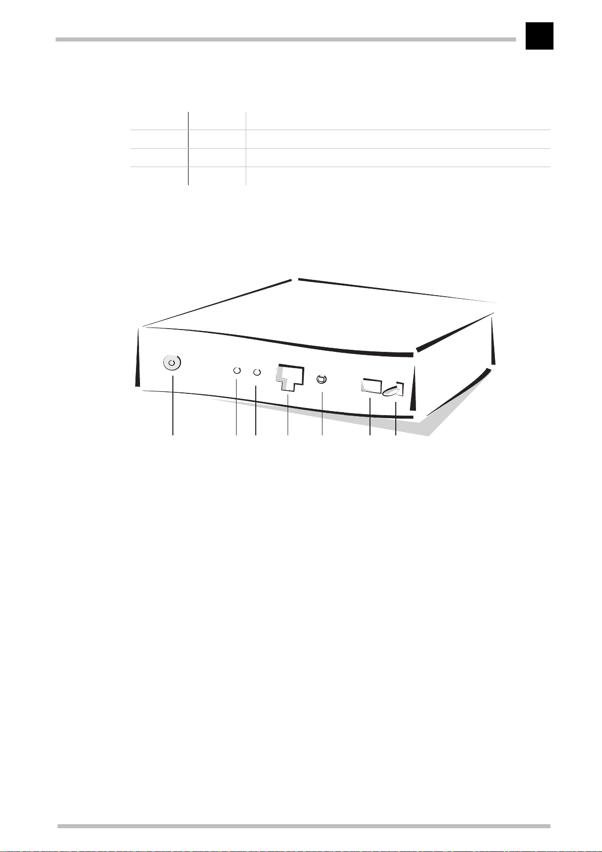
You will find a number of LEDs as display elements on the front panel.
ELSA MicroLink Cable
Page 10

Introducing the ELSA MicroLink Cable
2
ON
Standby
Cable-Tx, -Rx,
-Sync, Reg’d
This LED flashes once when the power supply is switched on. After the self-test, either
an error is output by a flashing light code or the device starts and the LED remains lit.
Off Unit switched off, power supply plugged in
red 1 x short Boot procedure (test and load) started
red flashing Display of a boot error (flashing light code)
red Device ready for use
This LED shows that the unit is in stand-by mode. The
ELSA MicroLink Cable
is registered
with the cable network provider in this state, but there is no active connection to the local
network. In other words, no data can be exchanged between the Internet and the LAN
in this state.
ELSA MicroLink Cable
The
can be switched to this mode by configuring the function of
the power switch correspondingly and then actuating this switch on the rear of the unit.
These LEDs display the status of the interface to the cable network:
Blink codes
Cable-Tx yellow Data packet sent from the device to the Internet
Cable-Rx green Data packet received from the Internet
Cable-Sync green The device has found a channel on which it can communicate with the
cable network operator's headend.
Cable-Reg’d green The registration and all required negotiations between the unit and the
headend have been completed and the registration confirmed by the headend. The unit is ready to exchange data with the Internet in this state.
The Sync and Reg’d LEDs can display the various phases of the cable modem registration
through combined blink codes, thus offering configuration troubleshooting information.
The meanings of the specific blink codes:
SYNC REG'd What has been achieved so
far?
off off channel search with 64/256QAM chan-
1 pulse off QAM lock FEC lock
2 pulse off FEC lock TRC lock
on off TRC lock initial ranging
What is the modem trying to do?
nel
on 1 pulse initial ranging DHCP
on 2 pulse DHCP ToD
on 3 pulse ToD Configuration file
on 4 pulse Configuration file Registration
on on Registration
ELSA MicroLink Cable
Page 11
Introducing the ELSA MicroLink Cable
3
LAN-Tx, -Rx,
LAN-Coll, -Link
These LEDs show the corresponding network controller status:
LAN -tx yellow Data packet sent from the device to the LAN
LAN-Rx green Data packet received from the LAN
LAN coll red Sending collision
LAN-Link green Connection to LAN is established and ready
Now turn the whole thing around and take a look at the rear. Beginning again on the lefthand side, you have:
ABC EFGD
1 Connector for the cable TV network (CATV)
2 Reset switch—performs a hardware reset
3 Factory Default button—the unit's factory defaults are restored after holding this
button for approx. 15 seconds
4 10Base-T network connection
5 Node/hub selector switch
6 Connection for power supply unit
7 On/standby switch
ELSA MicroLink Cable
Page 12

Introducing the ELSA MicroLink Cable
4
Node or hub?
Please check the position of the Node/Hub switch when connecting the unit to the LAN:
K As the factory default, the switch is set to 'Node'. In this setting, the device acts as
a node on a network. It can, in this case, only be connected to a hub, not directly to
the network card of a computer.
K Set the switch to 'Hub' if you do not wish to connect the device to a hub but directly
to a workstation. In this setting the lines for sending and receiving the data are
crossed.
Look at the link status LED (Link) to check if the node/hub switch is set correctly.
Shared media:
Multiple users
share a single
“cable”
The highlights of the
The cable modem is a new Internet-access technology that is now competing with
conventional modems, Internet modems and small ISDN routers. To take maximum
advantage of your
in which cable modems have the technological edge.
ELSA MicroLink Cable
ELSA MicroLink Cable
, you should know the areas and characteristics
Fast Internet
Cable modems use a split transfer rate depending on the direction of the signals.
Downstream refers to the transfer of data from the network operator to the participant,
upstream is the opposite direction. This asymmetrical split is quite acceptable, since
users generally receive far more information from the Internet than they send to it.
Cable network
Up to 43 Mbps can be transferred downstream; upstream transfer speeds reach up to 10
Mbps.
This colossal performance is shared by up to 2000 users connected to the same cable
section, however. This is referred to as the use of a shared media.
Bandwidth:
Throughput,
transfer
capacity
The data flow in the cable network does not take place at a constantly high volume, but
in irregular intervals. Also, it's unlikely that all 2000 participants will be using the
network simultaneously, so the available bandwidth is certainly adequate to ensure the
fast transfer of data.
The cable network operators have the option of limiting the available bandwidth for
individual participants, or offering several channels with 43 Mbps each. Please contact
your network operator for further information on transfer rates and pricing models.
ELSA MicroLink Cable
Page 13

Backbone
Introducing the ELSA MicroLink Cable
5
Backbone
direct
connection to
the Internet
:
The simple transfer rate between the network operator and participant does not by itself
determine the speed at which the Internet can be accessed. The network operator must
also forward data destined for the Internet to a backbone. The dimensioning of this
connection ultimately determines the speed at which you can surf. The backbone can
become a bottleneck if a large number of participants want to access Internet data
simultaneously and the network operator does not have an adequately dimensioned
connection to the Internet.
Internet at all times—always online
One of the biggest advantages of cable modem technology is the continuous availability
of the Internet. While “normal” Internet connections need to be established as required,
all cable modem users on a cable section can be permanently registered with the
headend. The multiport capabilities of the remote stations ensure that other participants
are not blocked due to a lack of connections. The advantages of this permanent Internet
connection:
K Immediate availability of all information
Your e-mail comes to you directly—not just when you pick it up. To view a Web
page, just open your browser and don't worry about connecting to your provider.
K Your own Internet server
Until now, running your own Internet server generally meant having an extremely
expensive leased line to the provider. Now you have one! If you would like to set
up your own Web server for your company, you can now do so and have it accessible
at all times via the cable modem at no additional cost.
More than just Internet
Together with the appropriate remote stations, cable modems form the connection
between network participants (private or business) and the network operator. Very high
throughputs—and thus very fast data transfers—can be realized using such a
connection. In addition to providing fast Internet access, this creates a number of other
interesting options for the evolution of network operators into information service
providers.
Regional content
Cable network operators generally have a local or regional orientation due to the
structure of the cable network. The headends that have to be additionally integrated into
the network with their restriction to around 2000 participants results in further area
limitations.
ELSA MicroLink Cable
Page 14

6
Proxy
Introducing the ELSA MicroLink Cable
Network operators can take advantage of this structure to provide regional content in
addition to the Internet. This can be accomplished by setting up Web servers that do not
need to be accessible from the Internet. These can then be used for special information
services for network participants, such as the programs of local cinemas, regional news,
information for clubs and special-interest groups, and so on—essentially, everything
that is of interest to the regional cable network participants, but that might be
superfluous on the Web.
Proxy servers
The network operator can also use local servers to speed up access to the Internet.
These proxy servers are used for the intermediate storage of information from the
Internet.
: Stand-in
Every page requested from the Internet by participants in the local cable network section
is stored in this proxy server for a specific period of time. As a rule, the storage period
on the proxy server is determined by the cable network operator. If another participant
requests the same page, the proxy server can serve the page directly without having to
find it on the Internet first.
This is generally beneficial, for example by speeding up downloads considerably.
However, when calling up information subject to frequent changes such as stock prices,
accessing the current Web page is usually a must. In such a case the version of the page
stored on the proxy server can already be out of date or incorrect. If this could be relevant
to you, please check with your network operators whether they deploy proxy servers.
Clicking the Refresh button will download the current information directly from the
Internet, however.
ELSA MicroLink Cable
Page 15

Introducing the ELSA MicroLink Cable
7
CE conformity and FCC radiation standard
CE
This equipment has been tested and found to comply with the limits of the European
Council Directive on the approximation of the laws of the member states relating to
electromagnetic compatibility (89/336/EEC) according to EN 55022 class B and EN55024.
FCC
This equipment has been tested and found to comply with the limits for a Class B digital
device pursuant to Part 15 of the Federal Communications Commission (FCC) Rules.
Operation is subject to the following two conditions:
1 This device may not cause harmful interference, and
2 This device must accept any inteference received, including interference that may
cause undesired operation.
The FCC ID of this device is KJGMLCABLE.
CE and FCC
These limits are designed to provide reasonable protection against radio frequency
interference in a residential installation. This equipment generates, uses, and can
radiate radio frequency energy. It may interfere with radio communications if not
installed and used in accordance with the instructions. However, there is no guarantee
that interference will not occur in a particular installation. If this equipment does cause
interference to radio or television reception (this can be determined by turning this
equipment off and on), the user is encouraged to try to correct the interference by one or
more of the following measures:
K Reorient or relocate the receiving antenna.
K Increase the distance between this equipment and the receiver.
K Connect the equipment to an outlet on a circuit other than that to which the receiver
is connected.
K Consult your dealer or an experienced radio/TV technician.
K Caution: To comply with the limits for an FCC Class B computing device, always use
a shielded signal cable.
The Federal Communications Commission warns the user that changes or modifications
to the unit not expressly approved by the party responsible for compliance could void the
user's authority to operate the equipment.
ELSA MicroLink Cable
Page 16

Introducing the ELSA MicroLink Cable
8
ELSA MicroLink Cable
Page 17
Installation and configuration
Installation and configuration
9
The aim of this chapter is to get you online as quickly as possible. First please check that
the contents of the package are complete:
ELSA MicroLink Cable
K
K Power supply
K Twisted-pair LAN connector cable
K WAN connector cable (coaxial) or corresponding adapter
K Documentation
K CD containing
Computers to be connected to the Internet using this device must fulfill the following
requirements:
K Any operating system that supports the TCP/IP network protocol, such as Windows
95, Windows 98, Windows NT 4.0, OS/2, Linux, BeOS
K Windows 95, Windows 98 or Windows NT 4.0 and a CD-ROM drive on the computer
on which you would like to install the
K Ethernet network adapter
K TCP/IP network protocol installed and bound to the network adapter
ELSA LANconfig
and electronic documentation
ELSA LANconfig
configuration software.
English
First, we will show you how to connect your new
ELSA LANconfig
the
unit will then be ready to connect your computer or network to the Internet.
If this is all going too fast for you or you're not familiar with the technical terms, you can
also find further information in this documentation, such as detailed descriptions of the
unit and its functions, sample configurations, descriptions of the software, glossaries,
etc.
This unit is designed to be connected to the broadband cable TV network. The connection
is made using the supplied coaxial cable or the appropriate adapter.
configuration software and perform the initial configuration. The
ELSA MicroLink Cable
, how to install
ELSA MicroLink Cable
Page 18
English
Installation and configuration
10
First Steps
Give it some power
1
First, give your device the power it needs through the power supply unit!
Onto the net
2
Connect the unit to your local network using the twisted pair cable. Please check the
position of the node/hub switch: 'Node' is the correct position when connecting the unit
to a network. Switch to 'Hub' when connecting the unit directly to a workstation.
The wire to the world
3
Connect the
adapter and a normal antenna cable. Data is transmitted through the cable TV network
in accordance with the MCNS (Multimedia Cable Network System)/DOCSIS standard.
ELSA MicroLink Cable
to the TV cable network using the coaxial cable or the
The connection to the cable TV network must provide a certain signal level. This value
will be checked by your cable network operator and adjusted as required.
And we're off
4
Switch the device on at the back. The 'Power' LED on the front panel lights up after a
short self-test. The 'LAN Link' LED indicates that the unit is correctly connected to the
LAN and that the Node/Hub switch is correctly set.
If this LED is not lit, change the position of the Node/Hub switch. If the LED still does not
light up, there may be a problem with the network adapter or the cabling.
Software installation
5
The
ELSA LANconfig
NT 4.0 may be used to configure the unit as required or to set it up for other applications.
Alternatively, you can perform the configuration via telnet from any other TCP/IP capable
computer (e.g. Linux, Solaris). Install the TCP/IP network protocol, followed by the
LANconfig
does not start up automatically after insertion of the CD, start Windows Explorer, click
on 'autorun.exe' on the
program.
on the computer that will be used to set up the device. If the setup program
configuration software for Windows 95, Windows 98 or Windows
ELSA MicroLink Cable
and follow the instructions in the install
ELSA
Configuring the
6
The first time
TCP/IP network and can immediately be configured.
When configuring the router with
quickly and conveniently guide you through the required settings.
ELSA MicroLink Cable
ELSA MicroLink Cable
ELSA LANconfig
is run, the new modem is automatically detected on the
ELSA LANconfig
, you can use the setup wizards to
Page 19

Installation and configuration
11
Quick Start: Quick configurations
We're sure that after you've installed the hardware and software, you'll want to get
going quickly without bothering with technical details. In the following sections, we'll
show you how to set up your
applications—without bothering with the whys and wherefores.
After the preparations that you should check in any case, we will introduce the
configuration of the unit as a bridge and IP router. Further information on the bridge and
router functions can be found in the 'Operating Modes' chapter.
ELSA MicroLink Cable
Preparations
The Internet is based on the TCP/IP network protocol. The individual devices in the
Internet (workstations, servers, routers, etc.) are identified using unique IP addresses. All
computers exchanging data on the Internet therefore must have the TCP/IP network
protocol installed and must be assigned a valid IP address.
quickly for the most common
English
IP addresses can either be manually entered, permanently for each computer, or assigned
automatically by a different computer, a so-called DHCP server. Your cable network
operator has such a DHCP server, and one is also contained in the
itself. For this quick-start, we prefer using the automatic assignment of an IP address by
a DHCP server. The cable network operator's DHCP server will be used when configuring
the unit as a bridge; in router mode the integrated DHCP server of the
will be used.
Cable
The following settings are required regardless of the operating mode you intend to use
with your
K Install the TCP/IP network protocol on all computers on the network.
K Activate the automatic assignment of IP addresses via DHCP for the workstations
Just how you do that will be explained in section 'How to set up the workstation
computers' towards the back of this chapter.
ELSA MicroLink Cable
(generally the default setting).
:
ELSA MicroLink Cable
ELSA MicroLink
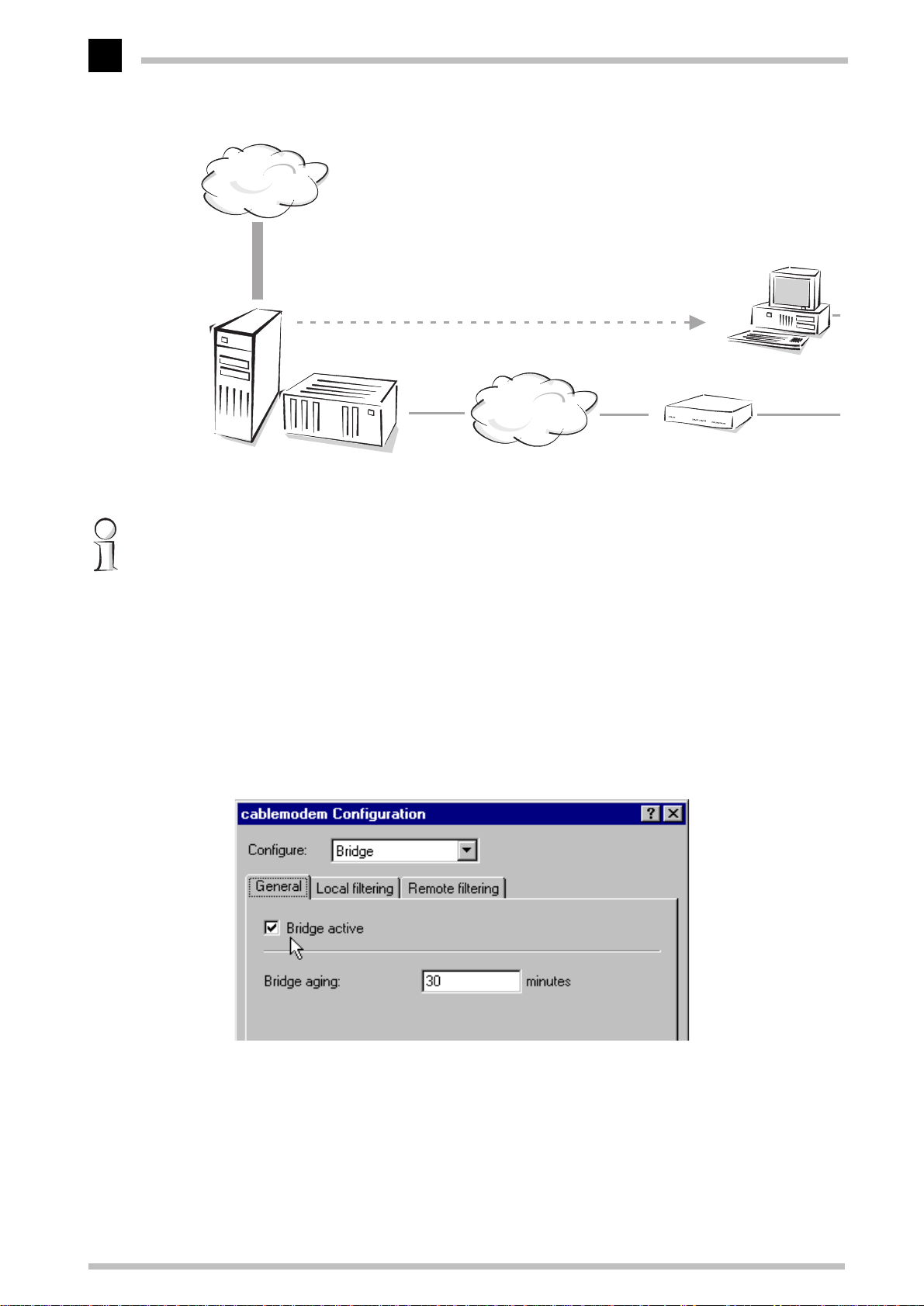
Configuration as a bridge
Bridge mode is the simplest configuration for the
the unit does not take IP addresses into consideration and transfers all data that is not
destined for workstations in the local network directly to the Internet. In the opposite
direction, all data coming from the Internet for a specific computer in the local network
is transferred (insofar as that computer has already sent data to the Internet). It's thus
not necessary to worry about the assignment of IP addresses. The computers in your
local network receive their IP addresses directly from the DHCP server of the cable
network operator.
ELSA MicroLink Cable
ELSA MicroLink Cable
. In this mode,
Page 20
English
Installation and configuration
12
Internet
Computer workstation in
LAN
IP address assignment
MCNS/
DOCSIS
Server with
DHCP
Headend Cable TV net-
work
ELSA MicroLink Cable
as bridge
In this example, only one computer is connected to the Internet via the ELSA MicroLink
Cable. In principle however, several computers can be connected to the ELSA MicroLink
Cable, using a hub for example, if the network operator permits.
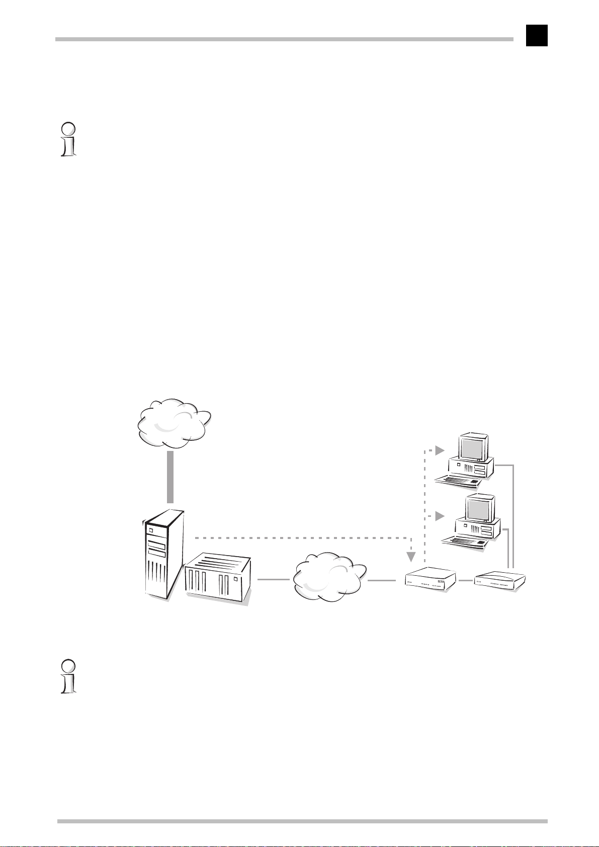
a Start up
LANconfig
ELSA LANconfig
.
b Click the entry for the
by clicking Start E Programs E ELSAlan E
ELSA MicroLink Cable
in the device list to open the
ELSA
configuration dialog. If an entry doesn't exist yet, create a new one using Device
E New. For the IP address, enter '10.0.0.254' or 'x.x.x.254', in which 'x.x.x' stands
for the addresses previously in use in your network, if applicable. Go to the 'Bridge'
section and activate the option 'Bridge' on the 'General' tab.
c Go to the 'TCP/IP' configuration section and on the 'Router' tab, disable the 'IP
Router' option. Also deactivate the DHCP server of your
the 'DHCP Server' tab, as well as the 'IP Masquerading' function on the
'Masquerading' tab.
d Save the configuration with OK.
ELSA MicroLink Cable
ELSA MicroLink Cable
on
Page 21
Installation and configuration
The
ELSA MicroLink Cable
is now ready for use in bridge mode. Open your Web browser,
and off you go into the Web with a whole new sensation of speed...
13
If you can only access the Internet with a single computer while using this configuration,
your cable network operator may have placed a limit on the maximum number of
connected computers. Either ask your network operator to increase the number, or
configure your ELSA MicroLink Cable as a router (with DHCP server and IP
masquerading).
If necessary, filters can be defined to restrict the exchange of data packets between the
local network and the Internet.
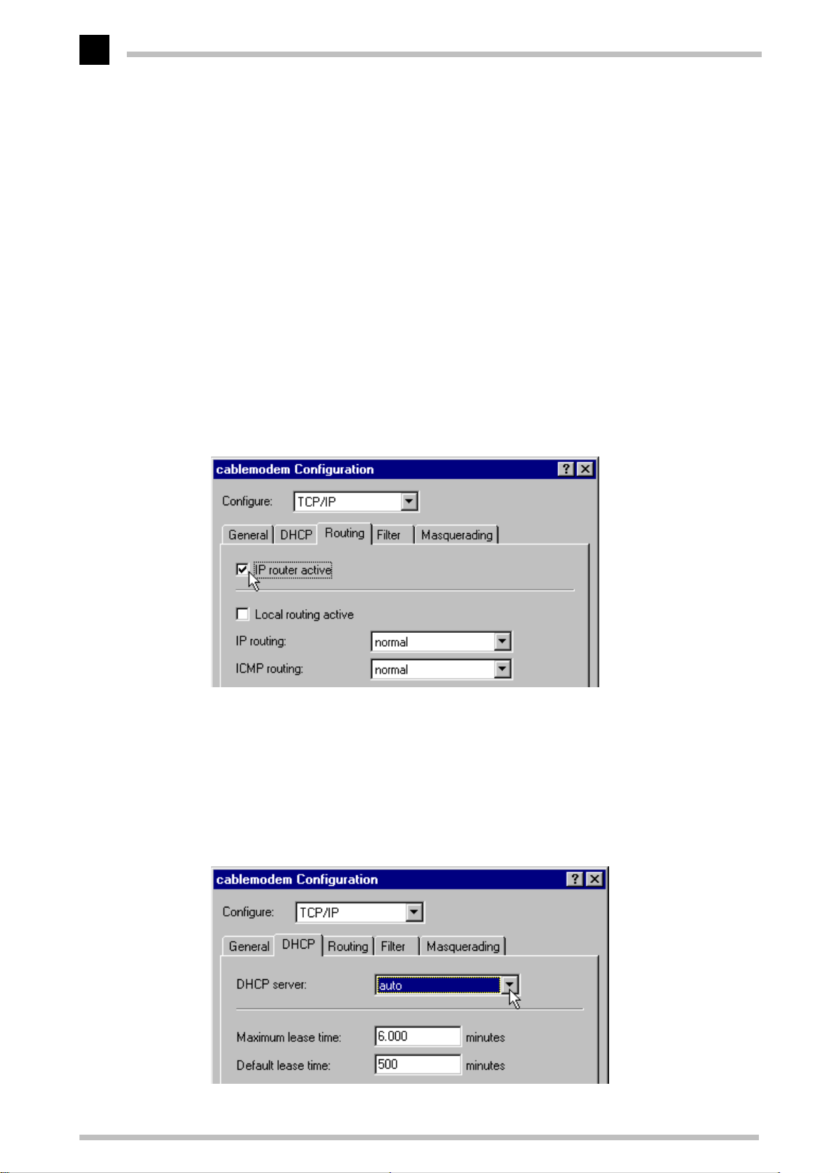
Configuration as a router
In addition to bridge mode, the
this mode, the
ELSA MicroLink Cable
computers exchanging data with the Internet. The exchange of data with the Internet can
thus be set up with much greater precision in this mode. The DHCP server and IP
masquerading functions will assist you with the administration of IP addresses in the
LAN.
Internet
ELSA MicroLink Cable
can also serve as an IP router. In
pays careful attention to the IP addresses of the
Computer workstation in
LAN
English
IP address assignment
IP address assignment
MCNS/
DOCSIS
Server with
DHCP
Headend Cable TV net-
work
ELSA MicroLink Cable
as router with DHCP server
Hub
In this example, several computers are connected to the ELSA MicroLink Cable, and thus
to the Internet, using a hub. In principle however, a single computer can also be
connected directly to the ELSA MicroLink Cable.
a Start up
LANconfig
ELSA LANconfig
.
by clicking Start E Programs E ELSAlan E
ELSA
ELSA MicroLink Cable
Page 22
English
Installation and configuration
14
b In order for a device to be able to assign addresses to other devices on a TCP/IP
network, it first needs an IP address valid in the LAN itself (LAN-IP address). Click
the entry in the device list to open the configuration dialog. If an entry doesn't exist
yet, create a new one using Device E New. For the IP address, enter '10.0.0.254'
or 'x.x.x.254', in which 'x.x.x' stands for the addresses previously in use in your
network, if applicable. Switch to the 'TCP/IP' configuration section and on the
'General' tab, enter the LAN IP address and the associated netmask.
– If you have not used any IP addresses on your network so far, you can assign any
address you like from the address space reserved for private use, e.g. '10.0.0.1'
with the subnet mask '255.255.255.0'. You are thereby also defining the address
space that the DHCP server will use for the other devices on the network.
– If you have already configured IP addresses on the computers on the LAN,
allocate a free address to the device from the address space you used previously.
c On the 'Router' tab, enable the 'IP Router' option.
d On the 'Masquerading' tab, enable the 'IP Masquerading' function. This will conceal
the IP addresses in use in your local network from the Internet. This protects your
network from intruders and avoids conflicts with other networks that may be using
the same addresses internally (also see IP addressing and IP masquerading).
e Go to the 'DHCP' tab and set the DHCP server to Auto mode. This lets the unit handle
the local IP address administration by itself. The
the valid address pool by itself unless you specify otherwise.
ELSA MicroLink Cable
determines
ELSA MicroLink Cable
Page 23

Installation and configuration
f Go then to the 'Bridge' section and deactivate the option 'Bridge' on the 'General'
tab.
15
g Save the configuration with OK.
ELSA MicroLink Cable
The
and off you go into the Web with a whole new sensation of speed...
is now ready for use in router mode. Open your Web browser,
If necessary, filters can be defined to restrict the exchange of data packets between the
local network and the Internet. This lets you define restrictions on the workstations that
can access the Internet, or on specific pages of the Internet that cannot be viewed.
Set up the workstation computers (Windows 95 or 98)
We will now briefly show you how the workstation computers must be set up (e.g. under
Windows 95 and Windows 98) to ensure problem-free communication between the
computers on the TCP/IP network and the router, if this has not already been done.
K TCP/IP installation
Install TCP/IP by clicking Start E Settings E Control Panel E Network E Add
E Protocol. Select 'Microsoft' under Manufacturers and 'TCP/IP' under Network
Protocols.
English
K Obtain IP addresses automatically (use DHCP)
Here's how to set individual workstations to automatically obtain an IP address:
Start E Settings E Control Panel E Network E TCP/IP E Properties E IP
Address E Obtain an IP address automatically . Delete any existing entries for
DNS servers and gateways on the 'Gateway' and 'DNS Configuration' tabs and
disable the 'DNS' option. When rebooting, the workstation will look for a DHCP
server in the network and will allow the server to assign it an IP address and a
netmask.
K Configuring fixed IP addresses (not using DHCP)
If you do not wish to use a DHCP server on your network you should configure fixed
IP addresses on your workstation computers: Start E Settings E Control Panel
E Network E TCP/IP E Properties E IP Address E Specify an IP address.
Allocate unique IP addresses, e.g. from a reserved address space. The workstations
can be assigned the addresses '10.1.1.2' to '10.1.1.253', for example, the
MicroLink Cable
Ensure that the address intended for the
available by opening a DOS box and entering the command
you do not receive a reply to this request the address is probably still unused.
the address '10.1.1.1', all with the netmask '255.255.255.0'.
ELSA MicroLink Cable
, i.e. '10.1.1.1', is
ping 10.1.1.1
ELSA
. If
ELSA MicroLink Cable
Page 24
English
Installation and configuration
16
Assign fixed IP addresses in router mode with activated IP masquerading only.
Otherwise, address conflicts with other users in your cable network may result when
using router mode without IP masquerading, or bridge mode.
K Specifying the gateway and the DNS server (not necessary if using DHCP)
Enter the LAN IP address of the
the gateway and domain name server (DNS server) in the individual workstations:
Start E Settings E Control Panel E Network E TCP/IP E Properties E
Gateway and DNS Configuration. You must also specify a host name for the DNS
configuration. Use the name of the PC for reasons of consistency, which, for
example, could be the same as the user name.
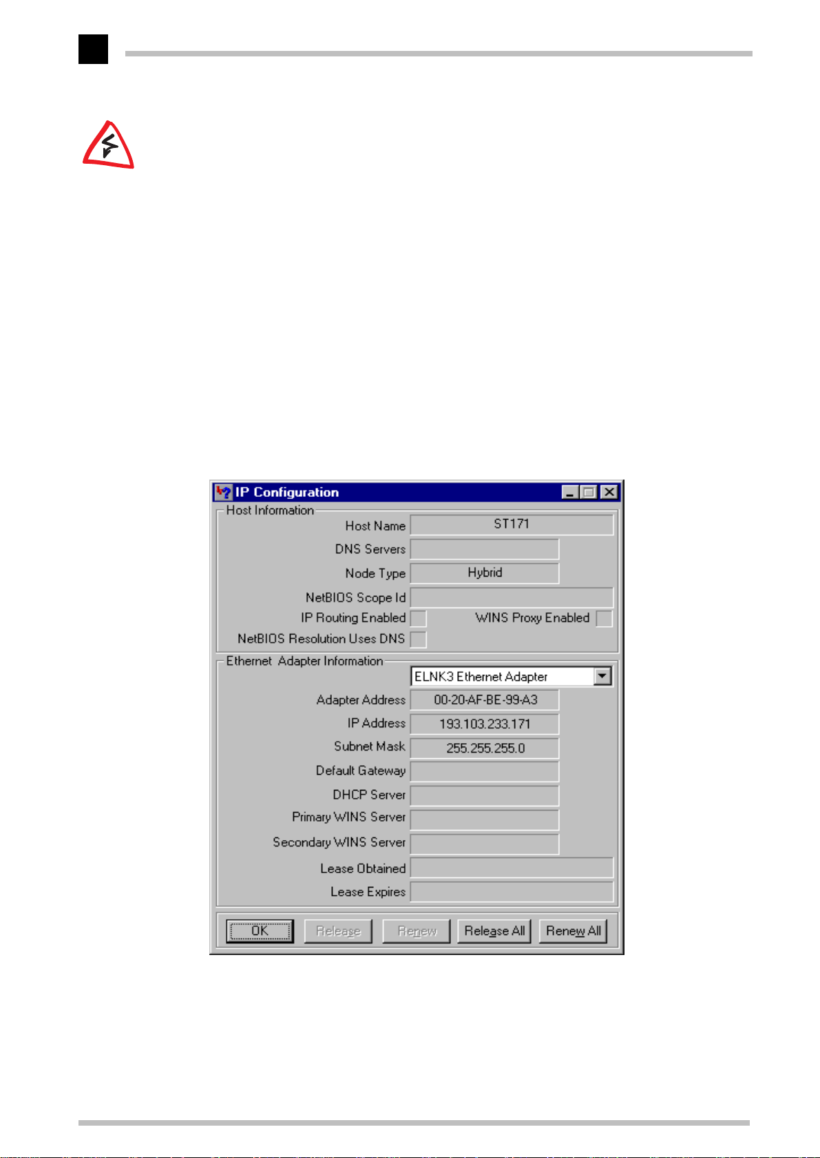
K Checking the IP configuration
Check the current IP configuration of the computer under Windows 95 or
Windows 98 by selecting Start E Run E winipcfg. Among other information, you
can see the IP address assigned to the computer by the DHCP server and the
addresses conveyed for the DNS server and gateway.
ELSA MicroLink Cable
in your own local network as
ELSA MicroLink Cable
Page 25

Configuration modes
Configuration modes
17
ELSA cable modems are always delivered with up-to-date software in which a number
of the settings have already been prepared for you.
It will nevertheless be necessary for you to add some information and configure them to
your specific needs. These settings are made as part of the configuration process.
This section will show you the programs and routes you can use to access the device and
set it up.
And, if the team at ELSA has produced firmware with new features, we will show you
how to load the new software.
The user-friendly method: inband
Using inband configuration allows any computer on the cable network or LAN to access
the router. However, this is only possible if the router permits it, as access from the
WAN or LAN can be restricted or completely blocked by the IP access list. Inband
configuration requires the use of either telnet (supplied with most operating systems) or
ELSA LANconfig
the
with your device. You can always obtain up-to-date releases from our online media.
configuration program for Windows.
ELSA LANconfig
is supplied
English
Requirements for inband configuration
TCP/IP or TFTP are used to make configurations using telnet or
TCP/IP protocol must therefore be installed on the computer being used and your cable
modem must be given an IP address which you will then use when addressing it.
A device that has not been configured yet will respond to the IP address
XXX.XXX.XXX.254, in which the Xs are placeholders for the network address in your LAN.
If the computers on your network have addresses such as 192.110.130.1, then you will
be able to address the router using 192.110.130.254.
If a computer with the address XXX.XXX.XXX.254 is already active on your network, shut
down the computer with this IP address before continuing. Give the device a new LAN
IP address as soon as you have established a connection to it, using ELSA LANconfig or
telnet.
ELSA LANconfig
. The
Alternatively: addresses can be managed by the DHCP server
If it is not absolutely essential that you configure the correct IP addresses manually, the
DHCP server can perform this task for you automatically. When using the DHCP server
you can have the IP addresses for all computers on the network assigned automatically
(see also chapter 'Automatic Address Administration with DHCP').
ELSA MicroLink Cable
Page 26
Configuration modes
18
English
Starting inband configuration using
After the installation (double-click on 'autorun.exe') is complete, call up the
LANconfig
ELSA LANconfig
E
network for
Just click on the Find button or call up the command with Device E Find to initiate a
search for a new device manually.
to search. You will only need to specify the local area network if using the inband
solution, and then you're off.
Once
found, together with their names and a description if available, the IP address and its
status.
configuration tool, for example by clicking on Start E Programs E ELSAlan
in the Windows task bar.
ELSA MicroLink Cable
devices.
ELSA LANconfig
ELSA LANconfig
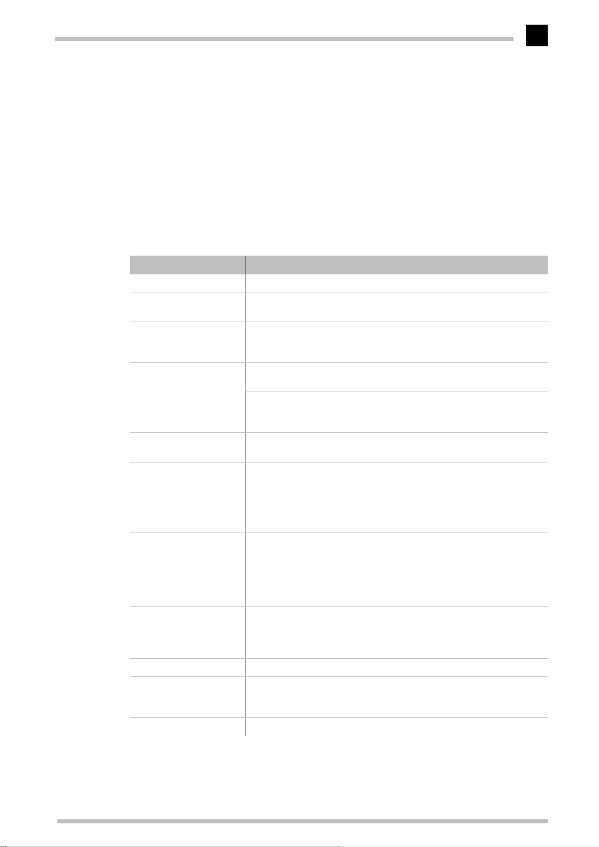
has finished its search, it displays a list of all the devices it has
ELSA LANconfig
ELSA LANconfig
will then prompt you for a location
searches the local area
ELSA
Double-clicking the entry for the highlighted device and then clicking the Configure
button or the Edit E Edit Configuration File option reads the device's current settings
and displays the general device information.
The remainder of the program's operation is essentially self-explanatory or covered in the
online help. You can click on the question mark top right in any window or right-click on
an unclear term at any time to call up context-sensitive help.
Start up inband configuration using telnet
Start inband configuration using telnet with the command from a DOS box:
telnet 10.1.80.125
Telnet will then establish a connection with the device using the IP address.
After the entry of the password (if you specified one to protect the settings) all
commands from the 'Configuration Commands' section are available.
ELSA MicroLink Cable
Page 27
Configuration modes
19
Configuration commands
Enter commands and path specifications using the normal DOS or UNIX conventions if
you are using telnet or a terminal program to configure the device.
Enter a forward slash or backslash to separate the path specifications. You do not need
to write out commands and table entries in full; an unambiguous abbreviation will do.
The entries for the categories MENU, VALUE, TABLE, TABINFO, ACTION and INFO will
be displayed while configurations are made and may be modified. You can use the
following commands to do this:
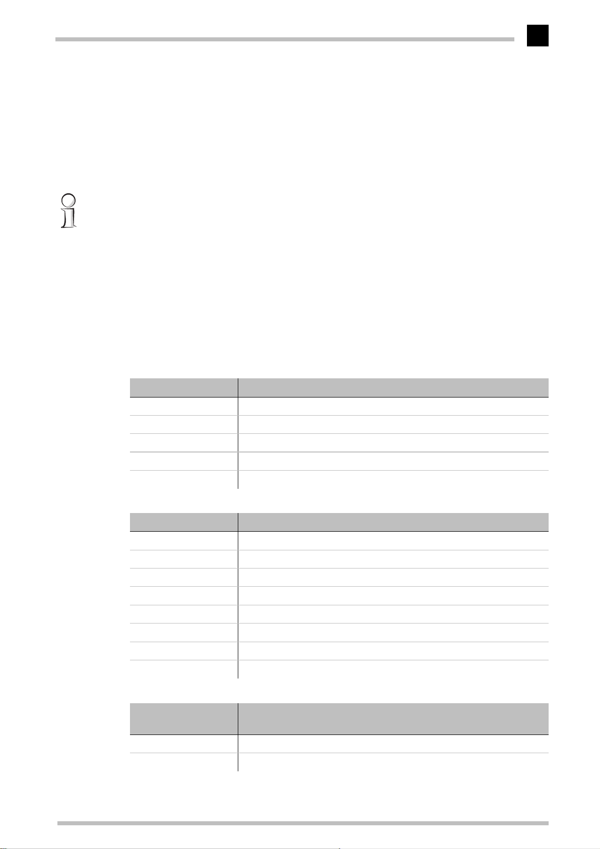
This command ... ... means this ... ... for instance:
? or help Calls up help text -
English
dir, list, ll, ls <MENU>,
<VALUE> or <TABLE>
cd <MENU> or <TABLE> Switches to the MENU or TABLE
set <VALUE> This resets the VALUE. set IP-address 192.110.120.140 sets a
set <VALUE> ? Shows you which values can be
del <VALUE> Deletes a table row. del /se/wan/nam/AACHEN
do <ACTION>
(parameters)
passwd Allows a new password to be
Displays the contents of MENU,
VALUE or TABLE
specified
Insert a space between all
entries in table rows. An *
leaves the entry unchanged.
specified here
Executes the ACTION according
to any parameters specified,
specified. The old password, if
there is one, must be entered
first. The new password must
then be entered twice and confirmed each time with y.
dir/status/wan-statistics displays the
current WAN statistics
cd setup/tcp-ip-module (or cd se/tc
for short) switches to the TCP/IP module
new IP address
set /setup/name AACHEN assigns
the name 'AACHEN' to the device.
Deletes the entry for the remote station AACHEN.
do /firmware/firmware-upload starts
the upload of new firmware.
repeat <sec> <ACTION> Repeats the ACTION at an inter-
val of the number of seconds
specified. Any key can be used
to terminate the repetition.
time Sets the system time and date. time 24.12.1998 18:00:00
language <language> Sets the language for the cur-
rent configuration session.
exit, quit, x Configuration is terminated.
repeat 3 dir/status/wan-statistics
displays the current WAN statistics
every 3 seconds
Languages currently supported:
English (language english)
German (language deutsch)
ELSA MicroLink Cable
Page 28

Configuration modes
20
Text entries with spaces are only accepted if they are placed in quotation marks, e.g.
set/se/snmp/admin "The Administrator"
.
English
Text entries (individual and table values) can be deleted as follows:
set /se/snmp/admin ""
ELSA MicroLink Cable
Page 29
What's happening on the line?
Configuration modes
21
Trace Outputs
Trace outputs may be used to monitor the internal processes in the cable modem during
or after configuration.
The trace outputs are slightly delayed behind the actual event, but are always in the
correct sequence. This will not usually hamper interpretation of the displays but should
be taken into consideration if making precise analyses.
How to start a trace
The command to call up a trace follows this syntax:
trace [code] [parameters]
The trace command, the code, the parameters and the combination commands are all
separated from each other by spaces. And what is lurking behind the code and
parameters?
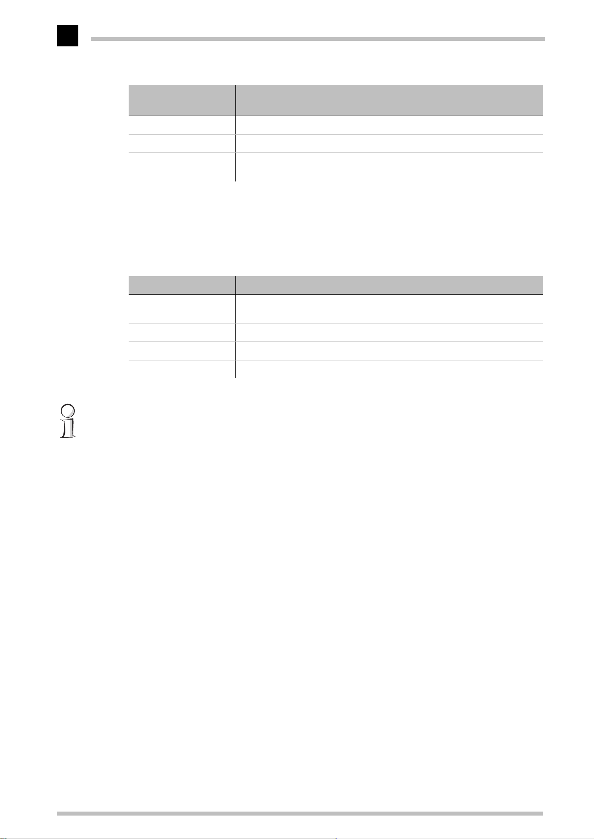
This code ... ... in combination with the trace causes the following:
? Displays a help text
+ Switches on a trace output
English
- Switches off a trace output
# Switches between different trace outputs (toggle)
no code Displays the current status of the trace
This parameter ... ... brings up the following display for the trace:
Status Status messages for the connection
Error Error messages for the connection
IP router IP routing
IP-RIP IP Routing Information Protocol
ICMP Internet Control Message Protocol
ARP Address Resolution Protocol
Masquerade Processes in the masquerading module
DHCP Dynamic Host Configuration Protocol
This combination
command
... brings up the following display for the trace:
All All trace outputs
Display Status and error outputs
ELSA MicroLink Cable
Page 30
Configuration modes
22
English
This combination
command
TCP-IP IP-Rt., IP-RIP, ICMP and ARP outputs
Time Displays the system time in front of the actual trace output
Source Includes a display of the protocol that has initiated the output in front of
... brings up the following display for the trace:
the trace.
Any appended parameters are processed from left to right. This means that it is possible
to call a parameter and then restrict it.
Examples
This code ... ... in combination with the trace causes the following:
trace Displays all protocols that can generate outputs during the configuration,
and the status of each output (ON or OFF)
trace + all Switches on all trace outputs
trace + all - icmp Switches on all trace outputs with the exception of the ICMP protocol
trace - time Switches off the system time output before the actual trace output.
You will find notes on the interpretation of trace outputs in the reference section of this
guide.
New firmware with FirmSafe
The software for the devices of ELSA is constantly being updated. We have fitted the
units with a flash ROM which makes child's play of updating the operating software so
that you can enjoy the benefits of new features and functions. No need to change the
EPROM, no need to open up the case: simply load the new release and you're away.
This is how FirmSafe works
FirmSafe makes the installation of the new software safe: The current firmware is not
simply overwritten but saved additionally in the device as a second firmware.
Only one of the firmware versions stored in the device can be active at any one time.
When new firmware is loaded the inactive firmware is overwritten. You can decide
which firmware version you want to activate after the upload:
K 'Immediate': The first option is to load the new firmware and activate it
immediately. The following situations can result:
– The new firmware is successfully loaded and then operates as desired.
Everything is then in order.
ELSA MicroLink Cable
Page 31
Configuration modes
– The device no longer responds after loading the new firmware. If an error occurs
during the upload, the router automatically reactivates the previous firmware
version and reboots the device.
K 'Login': To avoid problems with faulty uploads there is the second option with which
the firmware is uploaded and also immediately booted.
– The difference to the first option is that the router then waits five minutes for a
successful login to the device via outband or inband (via telnet). Only if this login
attempt is successful does the new firmware remain active permanently.
– If the device no longer responds and it is therefore impossible to log in, the router
automatically loads the previous firmware version and reboots the device with it.
K 'Manual': With the third option you can define a time period during which you want
to test the new firmware yourself. The router will start with the new firmware and
wait for the preset period until the loaded firmware is manually activated and
therefore becomes permanently effective.
23
English
How to load new software
There are various ways of carrying out a firmware upload (which is the term given to the
installation of software), all of which produce the same result:
K Configurations tool
K Terminal programs
K TFTP
All settings will remain unchanged by a firmware upload. All the same you should save
the configuration first for safety's sake (with Edit E Save Configuration to File if
ELSA LANconfig
using
If the newly installed release contains parameters which are not present in the device's
current firmware, the router will add the missing values using the default settings.
ELSA LANconfig
, for example).
ELSA LANconfig
When using the
selection list and click on Edit E Firmware Management E Upload New Firmware,
or click directly on the Firmware Upload button. Then select the directory in which the
new version is located and mark the corresponding file.
ELSA LANconfig
configuration tool, highlight the desired device in the
(recommended)
ELSA LANconfig
description and offers to upload the file. The firmware you already have installed will be
replaced by the selected release by clicking Open.
You also have to decide whether the firmware should be permanently activated
immediately after loading or set a testing period during which you will activate the
firmware yourself. To activate the firmware during the set test period, click on Edit E
Firmware Management E Upload New Firmware.
then tells you the version number and the date of the firmware in the
ELSA MicroLink Cable
Page 32

English
Configuration modes
24
TFTP
With TFTP you can use the writeflash command to install new firmware. To send a new
firmware version which, for example, is in the 'LC_1000U.130' file, to a router with the
IP address 194.162.200.17, you would enter the following command under Windows NT
for example:
tftp -i 194.162.200.17 put lc_1000u.130 writeflash
This command sends the corresponding file to the router using the writeflash
parameter. Binary file transfer must be set for TFTP. However, many systems have the
ASCII format preset. This example for Windows NT shows you how to achieve this by
using the '-i' parameter.
The device is booted up following a successful firmware upload and this activates the
new firmware switch directly. If an error occurs during the upload (write error in the flash
ROM, TFTP transmission error or similar) the device also boots and FirmSafe activates
the previous firmware. The configuration remains in operation.
It will only be possible to configure the device locally, i.e. via the outband interface, if it
is switched off during TFTP upload. The device will expect a firmware upload via the
serial port when it is switched back on.
You should therefore be sure to carry out a firmware upload only when you have a secure
(stable) connection.
With TFTP, other configuration commands can also be executed. The syntax is best
demonstrated with the following examples:
K tftp 10.0.0.1 get readconfig file1 : Reads the configuration from the device with the
address 10.0.0.1 and saves it as file1 in the current directory
K tftp 10.0.0.1 put file1 writeconfig : Writes the configuration from file1 to the device
with the address 10.0.0.1
K tftp 10.0.0.1 get dir/status/verb file2 : Saves the current connection information in
file2
Configuration using SNMP
General
The Simple Network Management Protocol (SNMP V.1 as specified in RFC 1157) allows
monitoring and configuration of the devices on a network from a single central instance.
This instance is commonly termed the“Manager” while the devices become“Agents”.
The structure permitted for SNMP information exchange is relatively simple. A manager
can access all SNMP-capable devices and services (agents) on the network. The access
rights are controlled via“Communities”.
ELSA MicroLink Cable
Page 33
Configuration modes
25
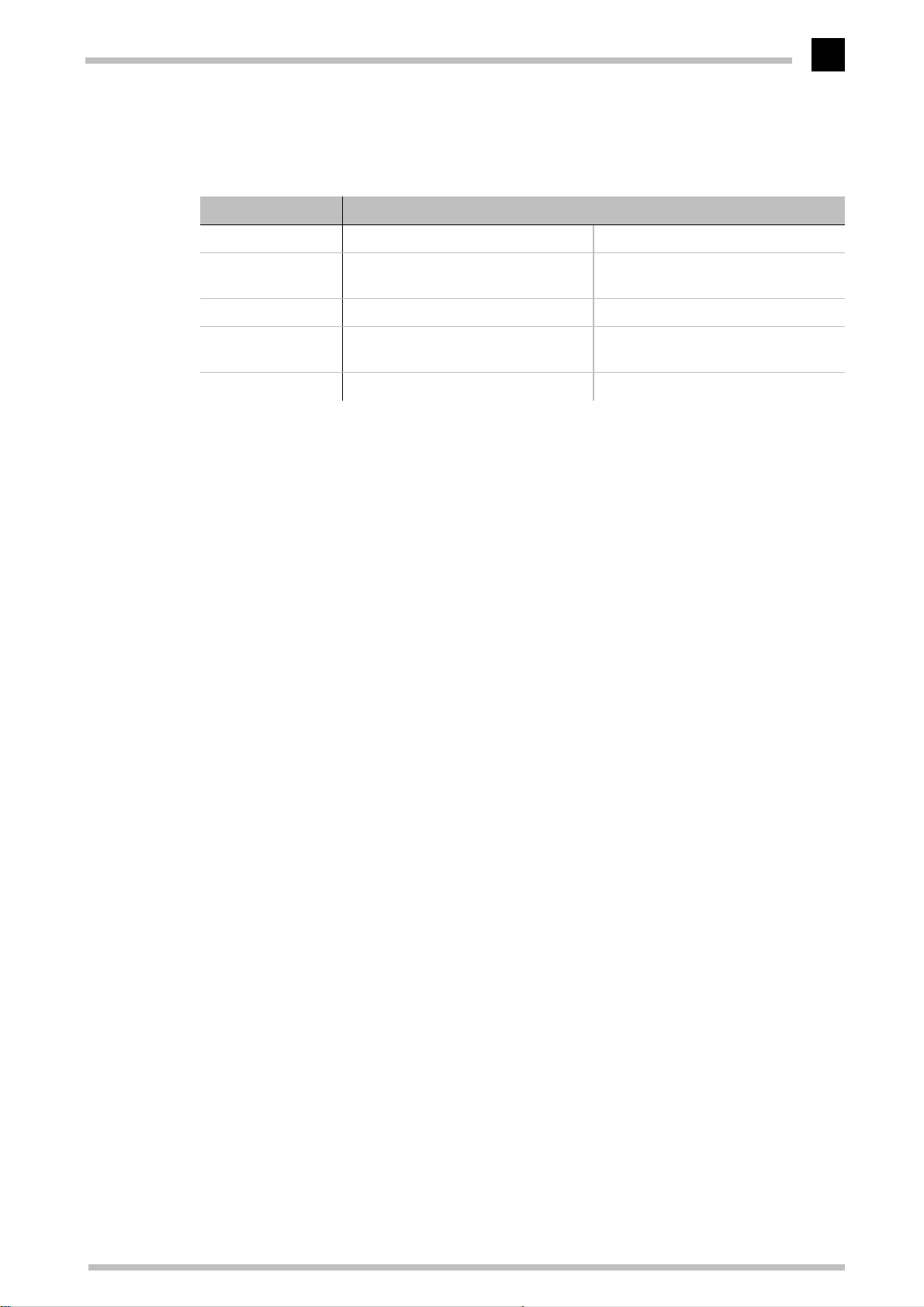
SNMP V.1 has only a very limited set of commands at its disposal, as the table below
shows:
Command Target/Source Function
GetRequest Manager – Agent retrieves information from the agent
GetNextRequest Manager – Agent retrieves the information contained in
the following MIB from the agent
SetRequest Manager – Agent modifies a setting in the agent
GetResponse Agent – Manager returns the queried value to the man-
ager
Trap Agent – Manager reports on an error or special status
These commands can be used for central monitoring and configuration of SNMP-capable
devices on a network. The SNMP capabilities of the agents are specified in so-called
MIBs = Management Information Bases.
The firmware of ELSA routers includes an implementation for an SNMP V.1 agent (in
accordance with RFC 1157). A part of MIB-2 and a private MIB, included in the product
as a separate file, are supported. This MIB must be loaded and translated by an SNMP
manager (HP OpenView, for example) to allow you to manage a device completely using
SNMP. All menus and parameters of the remote configuration will then be available to
you on a single branch of the SNMP management tree:
English
Accessing tables and parameters using SNMP
Any of the tables and parameters can be read and modified as necessary via the SNMP
interface. This also involves specifying in the MIB the variables which should have 'readonly' or 'read-write' status. Commercially available SNMP managers indicate 'read-only'
and 'read-write' status using color coding.
Access protection in SNMP V.1
Access to SNMP objects is controlled using so-called communities. A community is
basically a password used to govern access to particular classes of information. The
router permits read-only access to all parameters and tables through the 'public'
community. Bear in mind that this community cannot execute any write accesses.
You must use the device's password if you wish to write data using SNMP. Write access
using SNMP will not be granted as a matter of principle if the device's password is not
entered.
If the trapping mechanism is enabled and a failed access attempt is detected, an
'Authentication Failed' trap is triggered and sent to the manager(s) in the SNMP trap
table.
ELSA MicroLink Cable
Page 34
English
Configuration modes
26
Bear in mind that the access protection given by the community mechanism in the SNMP
V.1 is only very limited since the data, the MIB IDs and the communities are not encrypted
in the UDP data blocks of requests and responses as they are transmitted.
Deleting rows in tables using SNMP
SNMP itself has no mechanisms intended for deleting. You therefore have to use a trick
to delete entries from tables.
If you need to delete a row, you have to change the index entry value, i.e. the value in the
first column, to its current value.
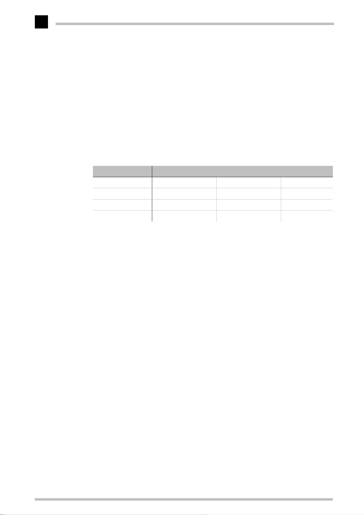
K Example: You want to delete the 3rd row from following IP routing table.
IP address IP-netmask Router name Distance
192.168.0.0 255.255.0.0 0.0.0.0 0
172.16.0.0 255.240.0.0 0.0.0.0 0
10.0.0.0 255.0.0.0 ROBERT 0
224.0.0.0 224.0.0.0 0.0.0.0 0
The entry '10.0.0.0' (i.e. the first cell of the third row) is amended in the manager to
its current value, i.e. to '10.0.0.0', and the Set command is sent off. The
SNMP SetRequest now contains the command to amend the first cell of the third
row to '10.0.0.0'. The SNMP software recognizes that this assignment to the index
is redundant and interprets it as a delete command.
Appending rows to tables using SNMP
There are two ways of inserting rows in a table:
K Using the set command will result in a new row through setting a new index entry.
By using the command in the syntax:
someTable.1.2.2 = xyz
a row with index '2' will be generated in the table 'someTable', with the entry 'xyz'
in its second column. The '1' after the table name is constant for this command and
stands for 'someEntry' in the SNMP-Syntax.
K When using SNMP managers that do not allow the entry of index values, it is
possible to amend any existing index entry to the new index value of the new row.
The row which has been used as the source for the amendment will itself remain
unchanged.
If we take Castlerock SNMPc as an example, the first possibility can be realized as
follows:
a Activate the Display MIB Table item in the Manage menu of Castlerock SNMPc.
ELSA MicroLink Cable
Page 35

Configuration modes
b Open the corresponding table. If the table is empty, then empty columns will be
displayed.
27
c Click on Edit. It is now possible to display the values for every single column in the
table.
d Enter the index of the table and the value for the column to be subsequently placed,
and click on Set at the right-hand side of the latter column.
A new column with the new index and the value for another column should now appear.
It is also possible to enter values for all columns of the row and simultaneously place all
columns, using Set All.
This procedure can also be carried out using Edit MIB Vars.. in the Manage menu. In
this case, click through to the table, single-click on the column to be placed, enter the
index in the field Variable Name after the name of this column and the new value in
Variable Value. After clicking Set, a new table row should appear.
Error messages via SNMP trap
Error or warning messages can be sent to a manager using the SNMP mechanism. The
SNMP agent contained in the router permits traps to be sent to up to 20 SNMP managers.
The IP addresses of these managers are configured in the Configuration menu under
/setup/SNMP-module/IP-Trap-Table
mission of trap messages using the
/setup/SNMP-module/Send-Traps
. You can enable and disable the trans-
switch.
English
The Management Information Base (MIB)
A textual representation of the configuration structure (the so-called private MIB) must
be supplied with the
access its configuration. The syntax of this MIB complies with ASN.1 (Abstract Syntax
Notation One, ISO 8824). There is usually a so-called MIB compiler included with the
SNMP management software. This compiler converts the MIB file into a form that can
be used by the manager.
The current ELSA MIB can be found both included with the product on CD and in the ELSA
online media.
ELSA MicroLink Cable
so that the SNMP management system can
ELSA MicroLink Cable
Page 36

English
Configuration modes
28
ELSA MicroLink Cable
Page 37

Operating modes and functions
29
Operating modes and functions
This section is an introduction to the functions and operating modes of your device. It
includes information on the following points:
K Security for your configuration
K Security for your LAN
K IP routing
K Bridging
K DHCP server
Along with the description of the individual points, we will also give you information to
support you as you configure your device.
Detailed sample configurations can be found in the Workshop.
Please refer to the electronic documentation for a detailed description of all parameters
and menus.
Security for your configuration
A number of important parameters for the exchange of data are established in the
configuration of the device. These include the security of your network, monitoring of
costs and the authorizations for the individual network users.
Needless to say, the parameters that you have set should not be modified by
unauthorized persons. The
protect die configuration.
ELSA MicroLink Cable
Password protection
The simplest option for the protection of the configuration is the establishment of a
password. As long as a password hasn't been set, anyone can change the configuration
of the device.
The password input field can be found in the configuration tool
'Management' configuration section on the 'Security' tab. The password prompt can be
activated in a terminal or telnet session in the
passw.prompt
passwd
.
menu. In this case, the password itself is set with the command
thus offers a variety of options to
ELSA LANconfig
/Setup/Config-Module/
in the
Login barring
The configuration in the
by barring logins. A brute-force attack is the attempt of an unauthorized person to crack
ELSA MicroLink Cable
is protected against “brute force attacks“
ELSA MicroLink Cable
Page 38

Operating modes and functions
30
a password to gain access to a network, a computer or another device. In order to do so,
a computer can, for example, go through all the possible combinations of letter and
numbers until the right password is found.
As a measure of protection against such attacks, the maximum allowed number of
unsuccessful attempts to Login can be set. If this limit is reached, the access will be
barred for a certain length of time.
These parameters apply globally to all configuration options (telnet, TFTP/
LANconfig
automatically barred too.
The following entries are provided in the configuration tool
configuring login barring in the 'Management' configuration area on the 'Security' tab or
under
K 'Lock configuration after' (
K 'Lock configuration for' (
and SNMP). If barring is activated on one port all other ports are
ELSA LANconfig
/Setup/Config-Module
Login-errors
Lock-minutes
in the menu:
)
)
ELSA
for
Access control via TCP/IP
Access to the internal functions of the devices through TCP/IP can be restricted using a
special filter list. Internal functions in this case means Telnet or TFTP sessions to
configure the
This table is empty by default and so access to the router can therefore be obtained by
TCP/IP using Telnet or TFTP from computers with any IP address. The filter is activated
when the first IP address with its associated network mask is entered and from that point
on only those IP addresses contained in this initial entry will be permitted to use the
internal functions. The circle of authorized users can be expanded by inputting further
entries. The filter entries can describe both individual computers and whole networks.
ELSA LANconfig
.
The access list can be found in the configuration tool
configuration section on the 'General' tab, or in the
Access List
Security for your LAN
You certainly would not like any outsider to access or edit the data on your computers.
ELSA MicroLink Cable
A
K Data encryption
K Data packet filtering
K IP masquerading (also known as NAT or PAT)
ELSA MicroLink Cable
menu.
ELSA LANconfig
/Setup/TCP-IP Module/
offers you various ways of restricting access from outside:
in the 'TCP/IP'
Page 39

Operating modes and functions
31
Encryption
Since cable modems transfer data via a cable shared by many participants, data should
be encrypted to prevent access by the other participants.
All data between the modem of the provider and the modem of the end users is
automatically transferred in an encrypted state. This is where the DES encryption (Data
Encryption Standard) with a code length of 56 comes in. In addition, the code in use is
repeatedly changed during the transfer of data. This guarantees the highest level of
protection.
TCP/IP packet filters
You can use your entries in the routing table to determine quite precisely which data
should be transferred. Additionally, you can use a special entry in the 'Router-name' field
to reject whole groups of IP addresses.
Occasionally, you may wish to restrict a transmission even further. You can do this using
a characteristic of TCP/IP, which is to send port numbers for destination and source as
well as the source and destination IP addresses with a data packet. The destination port
in a data packet stands for the service to be addressed in the TCP/IP network. The
destination ports are fixed for the various services on the TCP/IP network. The source
ports, on the other hand, may be selected freely within certain ranges.
The IP router can check the source and destination ports of data packets using the TCP
or UDP protocols. It can then deduce the purpose of the data from these ports. For
example, FTP accesses or Telnet sessions can be identified. The appropriate filter table
can be used to determine that certain data is not to be transferred from the LAN to the
remote station. Data for particular ports can also be blocked from entering the LAN in
the same way.
In addition to the definition of the port range and the associated protocols, the filter table
can be used to determine whether the data packet concerned will be accepted or
rejected. Both interfaces of the cable modem (for the cable network and for the LAN) can
be set separately for incoming and outgoing data transfer.
This filter table can be found in the configuration tool
configuration section on the 'Filter' tab, or in the
menu.
/Setup/IP router/firewall
ELSA LANconfig
in the 'TCP/IP'
The hiding place—IP masquerading (NAT, PAT)
One of today's most common tasks a for cable modem is connecting the numerous
workstation computers in a LAN to the ultimate network, the Internet. Everyone should
have the potential to access the WWW from his workstation and be able to fetch bang
up-to-date information for his work.
ELSA MicroLink Cable
Page 40

Operating modes and functions
32
But this provokes objections from the network manager responsible for the security of
data on the company's network: Every workstation computer on the WWW? Surely this
means that anyone can get in from outside?—Not true!
IP masquerading provides a hiding place for every computer while connected with the
Internet. Only the router module of the unit and its IP address are visible on the Internet.
The computers in the LAN then use the router as a gateway so that they themselves
cannot be detected. To do this, the router separates Internet and intranet, as if by a wall.
Therefore, IP masquerading is also called a “firewall function“.
For further information, see the 'IP Routing: IP masquerading' section.
IP routing
This chapter describes the function of the cable modem as an IP router. Whenever the
IP router (or simply the router) is mentioned in the next paragraphs, this is a reference to
the corresponding operating mode of the cable modem.
An IP router works between networks which use TCP/IP as the network protocol. This
only allows data transmissions to destination addresses entered in the routing table.
This chapter explains the structure of the IP routing table of an ELSA router, as well as
the additional functions available to support IP routing.
The IP routing table
Use the IP routing table to tell the router which remote station (which other router or
computer) it should send the data for particular IP addresses or IP address ranges to. This
type of entry is also known as a “route“ since it is used to describe the path of the data
packet. This procedure is also called “static routing“ since you make these entries
yourself and they remain unchanged until you either change or delete them yourself.
Naturally, there is also “dynamic routing“ too. The routers use the routes in this way to
exchange data between themselves and continually update it automatically. The static
routing table can hold up to 64 entries, the dynamic table can hold 128. The IP router
looks at both tables when the IP/RIP is activated.
The routing table can be found in the configuration tool
configuration section on the 'Router' tab, or in the
routing
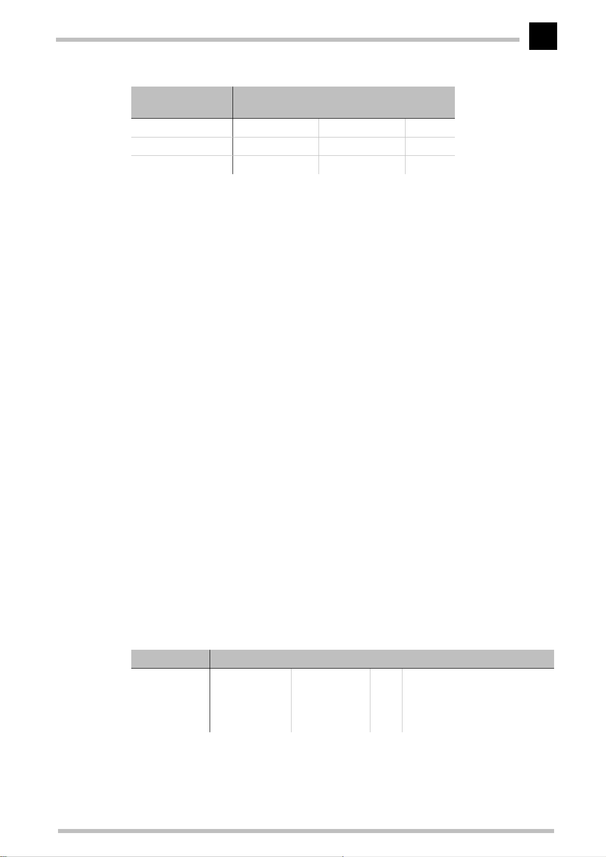
menu. This, then, is how an IP routing table might look:
ELSA LANconfig
/Setup/IP router/IP
in the 'TCP/IP'
IP address IP netmask Router Dis-
192.168.0.0 255.255.0.0 0.0.0.0 0
172.16.0.0 255.255.0.0 0.0.0.0 0
10.0.0.0 255.0.0.0 0.0.0.0 0
ELSA MicroLink Cable
tance
Page 41
Operating modes and functions
IP address IP netmask Router Dis-
tance
224.0.0.0 224.0.0.0 0.0.0.0 0
255.255.255.255 0.0.0.0 CABLE 1
192.168.130.0 255.255.255.0 191.168.140.123 1
What do the various entries on the list mean?
K IP addresses and IP network masks
This is the address of the destination network to which data packets may be sent
and its associated network mask. The router uses the network mask and the
destination IP address of the incoming data packets to check whether the packet
belongs to the destination network in question.
The route with the IP address "255.255.255.255" with a network mask of "0.0.0.0" is
the default route. Any data packets which cannot be routed by other routing entries
are transmitted via this route.
33
K Router Name
The router name indicates what should be done with the data packets that
correspond to the IP address and the network mask.
Routes with the router name "0.0.0.0" describe Exclusion routes. Data packets for
this “zero route“ are rejected and are not routed any further. This is how routes
which are forbidden on the Internet (private address spaces, e.g. 10.0.0.0), for
example, are excluded from transmission.
If a router name consists of an IP address, this means we are dealing with a locally
accessible router, responsible for the transmission of the appropriate data packets.
By default, you will find the entry „CABLE“ in the cable modem, as a router name at
the default route. All IP data packets transferred via this route are forwarded to the
cable interface.
K Distance
Number of routers between your own and the destination router.
Examples with explanatory notes:
IP address IP netmask Router name Dist. This is what happens:
192.168.130.0 255.255.255.0 192.168.140.123 0 All data packets with destination
IP addresses 192.168.130.x are
transmitted to the locally accessible router with the IP address
192.168.140.123.
ELSA MicroLink Cable
Page 42
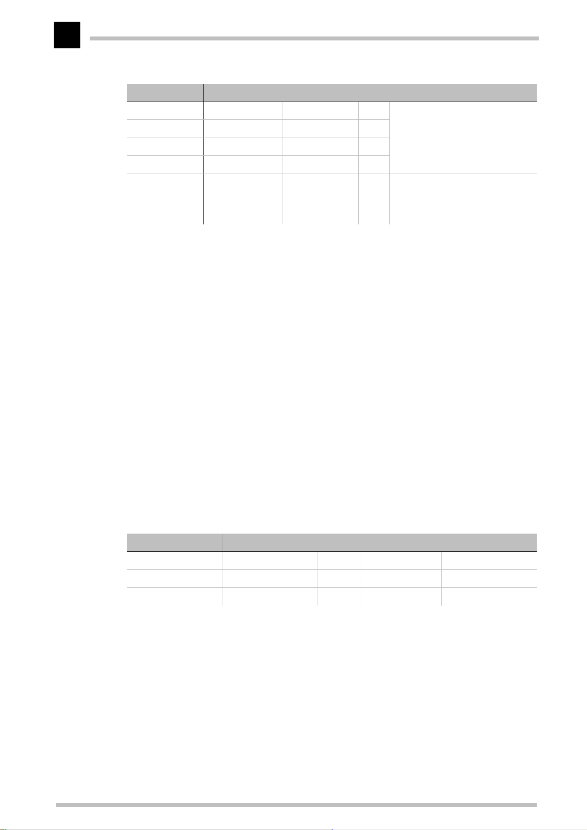
Operating modes and functions
34
IP address IP netmask Router name Dist. This is what happens:
192.168.0.0 255.255.0.0 0.0.0.0 0 Excludes transmission of all data
172.16.0.0 255.255.0.0 0.0.0.0 0
10.0.0.0 255.0.0.0 0.0.0.0 0
224.0.0.0 224.0.0.0 0.0.0.0 0
255.255.255.255 0.0.0.0 CABLE 1 All data packets which cannot be
Dynamic routing with IP/RIP
In addition to the static routing table ELSA routers also have a dynamic routing table
containing up to 128 entries. Unlike the static table, you do not fill this out yourself, but
leave it to be dealt with by the router itself. It uses the Routing Information Protocol (RIP)
for this purpose. This protocol is used by all devices with RIP to exchange information
regarding the reachable routes.
packets to networks using private
address spaces.
allocated to the entries listed
above are transmitted into the
cable network.
What information is propagated by IP/RIP?
A router uses the IP/RIP information to inform the other routers in the network of the
routes it finds in its own static table. The following entries are ignored in this process:
K Rejected routes with the '0.0.0.0' router setting.
K Routes referring to on other routers in the local network.
Which information does the router take from received IP/RIP packets?
When the router receives such IP/RIP packets, it incorporates them in its dynamic routing
table, which looks something like this:
IP address IP netmask Time Distance Router
192.168.120.0 255.255.255.0 1 2 192.168.110.1
192.168.130.0 255.255.255.0 5 3 192.168.110.2
192.168.140.0 255.255.255.0 1 5 192.168.110.3
What do the entries mean?
IP addresses and network masks identify the destination network, the distance indicates
the number of routers between sender and receiver, the final column indicates the router
which announced this route. This leaves the 'Time'. The dynamic table thus shows how
old the relevant route is. The value in this column acts as a multiplier for the intervals at
which the RIP packets arrive. A '1', therefore, stands for 30 seconds, a '5' for about 2.5
minutes and so on. New information arriving about a route is, of course, designated as
directly reachable and is given the time setting '1'. The value in this column is
ELSA MicroLink Cable
Page 43

Operating modes and functions
automatically incremented when the corresponding amount of time has elapsed. The
distance is set to '16' after 3.5 minutes (route not reachable) and the route is deleted
after 5.5 minutes.
Now if the router receives an IP/RIP packet, it must decide whether or not to incorporate
the route contained into its dynamic table. This is done as follows:
K The route is incorporated if it is not yet listed in the table (as long as there is enough
space in the table).
K The route exists in the table with a time of '5' or '6'. The new route is then used if
it indicates the same or a better distance.
K The route exists in the table with a time of '7' to '10' and thus has the distance '16'.
The new route will always be used.
K The route exists in the table. The new route comes from the same router which
notified this route, but has a worse distance than the previous entry. If a device
notifies the degradation of its own static routing table in this way, the cable modem
will take this into account and include the poorer entry in its dynamic table.
35
The interaction of static and dynamic tables
The router uses the static and dynamic tables to calculate the actual IP routing table it
uses to determine the path for data packets. In doing so, it includes the routes from the
dynamic table which it does not know itself or which indicate a shorter distance than its
own (static) route with the routes from its own static table.
Local routing
You know the following behavior of a workstation within a local network: The computer
searches for a router to assist with transmitting a data packet to an IP address which is
not on its own LAN. This router is usually notified to the operating system by its property
of being the default router or gateway. It is often only possible to enter one default router
which is supposed to be able to reach all the IP addresses which are unknown to the
workstation computer if there are several routers in a network. Occasionally, however,
this default router cannot reach the destination network itself but does know another
router which can find this destination.
How else can you assist the workstation computer?
By default, the router sends the computer a response with the address of the router
which knows the route to the destination network (this response is known as an ICMP
redirect). The workstation computer then accepts this address and sends the data packet
straight to the other router.
Certain computers, however, do not know how to handle ICMP redirects. To ensure that
the data packets reach their destination anyway, use local routing (in
the 'TCP/IP' configuration section on the 'Router' tab or in the /
Setup/IP Router
ELSA LANconfig
in
ELSA MicroLink Cable
Page 44

Operating modes and functions
36
Module/Local Routing On
the data packet to the other responsible router. The router will then no longer send any
ICMP redirects.
This may seem to be a good idea in principle, but local routing should still only be used
as a last resort, since this function leads to doubling of the number of data packets being
sent to the destination network required. The data is first sent to the default router and
is then sent on from there to the router in the local net which is actually responsible.
menu). This tells the router in your device to send
IP masquerading (NAT, PAT)
One continually growing problem for the Internet is the limited number of generally valid
IP addresses available. In addition to this, the allocation of fixed IP addresses for the
Internet by the Network Information Center (NIC) is an expensive process. What is more
obvious than having several computers share one IP address?
This particular solution is called IP masquerading. This is a procedure whereby only one
LAN router appears on the Internet with an IP address. This IP address is allocated to the
router either permanently by the NIC or temporarily by an Internet provider. All the other
computers on the network then “conceal“ themselves behind this one IP address. Aside
from the welcome savings, IP masquerading has the added benefit of guarding very
effectively against attacks on the local network from the Internet.
The IP masquerading function is connected to the operating mode of the cable modem as
a router. Whenever routers are mentioned in the following paragraphs, this is a
reference to the cable modem in the operating mode of an IP router.
Two addresses for the router
Masquerading pits two opposing requirements of the router against one another:
K On the one hand, it has to have a valid IP address in the local network of the user so
that it can be reached from the LAN.
K On the other hand, it has to have a valid address in the cable network.
Since these two addresses may not in principle be located on the same logical network,
there is only one solution: two IP addresses are required.
ELSA MicroLink Cable
Page 45
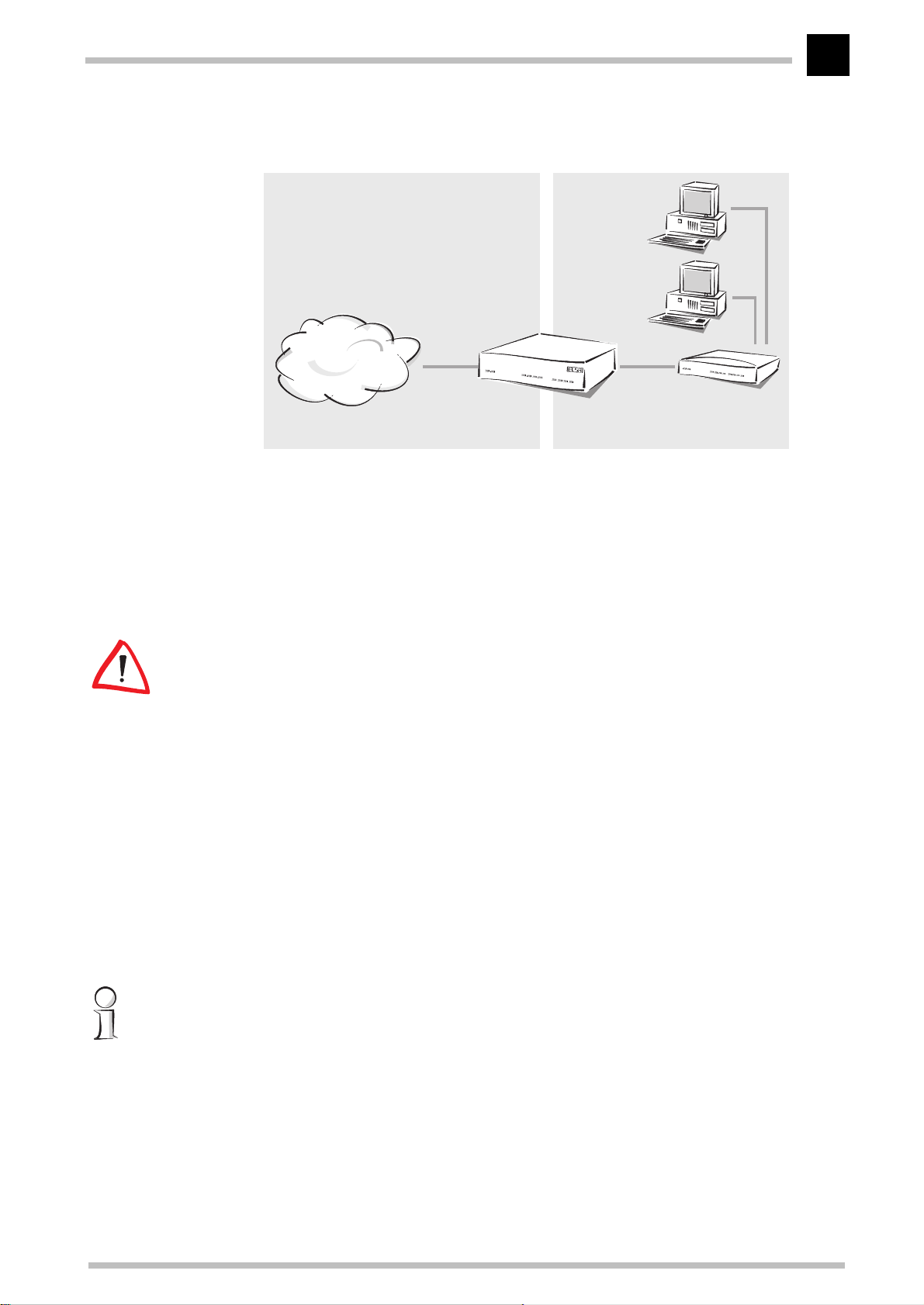
Operating modes and functions
37
Cable TV network
Cable IP address LAN IP address
MCNS
ELSA MicroLink
LAN of the user
Hub
Cable
The cable modem is therefore assigned a cable IP address and a LAN IP address, each
with its own appropriate network mask. Use the 'Masquerade' option to inform the cable
modem which of the two addresses to use when transferring the packets.
K 'Off': No masquerading.
K 'on': Use this entry to apply the cable IP address that was assigned during the
registration at the headend by the network operator.
If the cable modem is used as an IP router without masquerading, make sure that IP/RIP
is enabled. When using it as an IP router with masquerading, IP/RIP should be disabled.
How does IP masquerading work?
Masquerading makes use of a characteristic of TCP/IP data transmission, which is to use
port numbers for destination and source as well as the source and destination addresses.
When the router receives a data packet for transfer it now notes the IP address and the
sender's port in an internal table. It then gives the packet its unique cable IP address
and a random new port number. It also enters this new port on the table and forwards
the packet with the new information.
The response to this new packet is now sent to the cable IP address of the cable modem
with the new sender port number. The entry in the internal table allows the router to
assign this response to the original sender again.
You can view these tables in detail in the router statistics (see also 'Status').
Simple and inverse masquerading
This masking operates in both directions: The local network behind the cable IP address
of the router is masked if a computer from the LAN of the user sends a packet to the
Internet (simple masquerading).
If, on the other hand, a computer sends a packet from the Internet to, for example, an FTP
server on the LAN, from the point of view of this computer the router appears to be the
ELSA MicroLink Cable
Page 46

Operating modes and functions
38
FTP server. The router knows the IP address of the FTP server in the LAN from the entry
in the service table (in
'Masq.' tab or in the
Table
the FTP server in the local network (answers from the server) are hidden behind the IP
address of the router.
The only small difference is that:
K Access to a service (port) in the user's LAN from outside must be defined in advance
K When accessing the Internet from the LAN, on the other hand, the router itself
menu). The packet is forwarded to this computer. All packets that come from
by specifying a port number. The destination port is specified with the LAN IP
address of, for example, the FTP server, on a service table to achieve this.
makes the entry in the port and IP address information table.
The table concerned can hold up to 2048 entries, that is it allows 2048
simultaneous transmissions between the masked and the unmasked network.
ELSA LANconfig
Setup/IP Router Module/Masquerading/Service
in the 'TCP/IP' configuration section on the
After a specified period of time, the router, however, assumes that the entry is no
longer required and deletes it automatically from the table.
Which protocols can be transmitted using IP masquerading?
Naturally, only those which also communicate using ports. Protocols working without
port numbers or using ports above IP in the OSI model cannot be masked without special
treatment.
The current version of router implements masquerading for the following protocols:
K TCP (and all TCP-based protocols such as FTP, HTTP etc.)
K UDP
K ICMP
DNS forwarding
Names rather than IP addresses are generally used to access a server over the Internet.
Who knows which address is behind 'www.domain.com'? The DNS server, of course.
DNS stands for Domain Name Service refers to the assignment of domain names (such
as domain.com) to the corresponding IP addresses. This information must be constantly
updated and be accessible all over the world at any time. DNS servers holding long
tables containing IP addresses and domain names exist for this purpose.
If a computer calls up a home page from the intranet, it first sends out a DNS request:
“What is the IP address associated with www.domain.com?”
This request is dealt with as follows if the cable modem is registered as the DNS server
for the workstation computers:
ELSA MicroLink Cable
Page 47
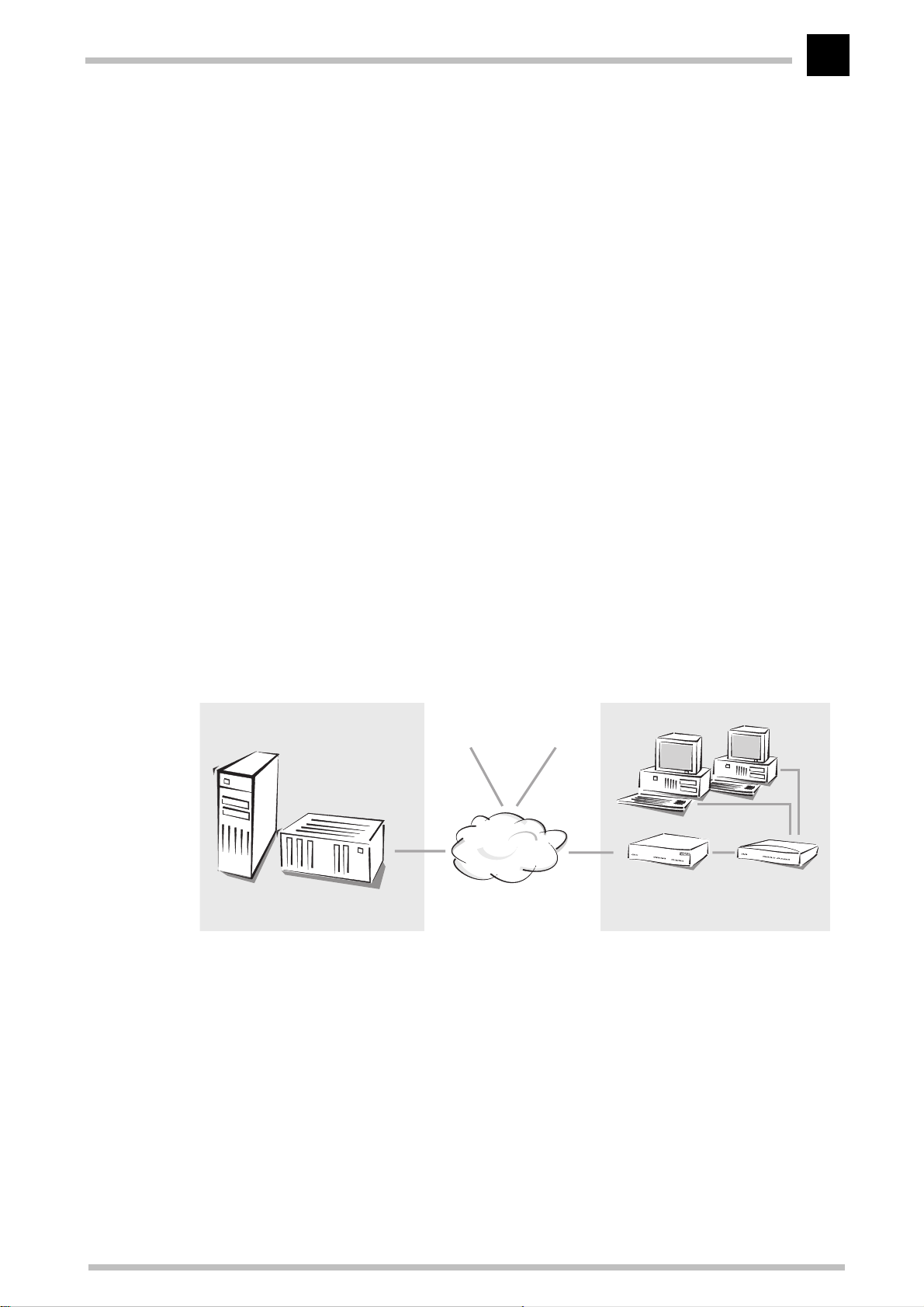
Operating modes and functions
39
K Initially the router checks whether a DNS server has been entered in its own
settings (in configuration tool
ELSA LANconfig
on the 'Addresses' tab or in the /
Setup/TCP-IP Module
in the 'TCP/IP' configuration section
menu). If it finds it
there, it will then retrieve the desired information from this server.
K If no DNS server has been entered in the cable modem, it tries to reach the network
operator's DNS server to retrieve the IP address associated with the name. The
address of the DNS at the network operator is transferred during the registration of
the cable modem by the headend.
This procedure does not require you to have any knowledge of the DNS server address.
Entering the LAN IP address of the cable modem as the DNS server for the workstation
computers is sufficient to enable name associations. This procedure also automatically
updates the address of the DNS server. Your local network always receives the most
current information even if, for example, the provider sending the address changes the
name of his DNS server or you change to another provider.
Bridging
A bridge connects two or more LANs in such a way that they appear to be a single large
network. When bridging via cable modems, the LAN of the cable network operator with
the headend is on one side and the LAN of the network participants with the cable
modem and the local workstations on the other.
LAN of the cable network operator
Headend
In the bridge operating mode, the
further connected cable
modems
MCNS
Cable TV network
ELSA MicroLink Cable
without locally assigned MAC addresses, between the local network or another local
area network (LAN) or a workstation on one side and the cable network on the other side.
LAN of the user
ELSA MicroLink
Cable
Hub
transfers all data to computers
The bridge thus learns on its own which MAC addresses are located on its own network
and which are located on the other side. After a very high level of data traffic that occurs
during the initial negotiations between the two LANs, the network load drops sharply.
When receiving data from the cable network, the bridge in the cable modem uses the
MAC addresses to determine whether the data is destined for its own LAN. The bridge
will only accept data packets that are addressed to MAC addresses in its LAN.
ELSA MicroLink Cable
Page 48

Operating modes and functions
40
What are the filter options?
You may not always wish to transfer all data. Much of the data which is bouncing around
in the LAN is of no interest to remote networks or computers. You can thus block transfer
of the following data packets via the bridge:
K Broadcast packets: Data directed at all devices accessible in a network (
Bridge-Module/LAN-config/Broadcast
K Multicast packets: Data which is transferred to all devices accessible in a group
Setup/Bridge-Module/LAN-config/Multicast
(
Special filter lists which exclude certain addresses from a transmission or only
allow certain addresses can be set up to handle this data. The bridge filters
differentiate here between destination and source addresses. You can first
establish for both address types whether the associated table contains the
addresses to which data is to be transmitted (
config/Dest.-address/Filter-type/pos
excluded (
filtered into the table itself.
.../Filter-type/neg
). You then enter the MAC addresses to be
).
).
Setup/Bridge-Module/LAN-
) or the addresses to be
Setup/
This method of filtering by entering the exact MAC address naturally demands a certain
degree of maintenance effort. Should the addresses change, when a network adapter is
changed for example, the new addresses must be entered to ensure that the bridge
continues to function.
Automatic address administration with DHCP
In order to operate smoothly in a TCP/IP network, all the devices in a local network must
have unique IP addresses.
In addition to the IP addresses, the devices in the LAN also need the addresses of DNSs
as well as that of a default gateway through which the data packets are to be routed from
addresses that are not available locally.
In a smaller network, it is still conceivable that these addresses could be entered
manually in all the computers in the network. In a larger network with many workstation
computers, however, this would simply be too enormous of a task.
In such situations, the DHCP (Dynamic Host Configuration Protocol) is the ideal solution.
Using this protocol, a DHCP server in a TCP/IP-based LAN can dynamically assign the
necessary addresses to the individual stations.
ELSA MicroLink Cable
Page 49

Operating modes and functions
The cable modem really belongs to two LANs:
K On one side it is a part of the LAN of the cable network operator and forms a LAN
together with the headend and all connected cable modems. The cable network
operator assigns the IP addresses to the participants via DHCP.
K On the other side the cable modem forms a separate LAN with one or more
connected computers. DHCP can also be used to manage addresses within your
own LAN.
The cable modem thus functions as a DHCP client and as a DHCP server.
41
Whenever IP addresses of the cable modem are mentioned in the following paragraphs,
this is a reference to the LAN IP address of the ELSA MicroLink Cable, unless something
else is explicitly stated.
The DHCP client
The cable IP address for the exchange of data in the cable network is assigned via DHCP
by the network operator during registration at the headend, i.e. the network participant
has no influence on this process. Apart from the IP address used by the cable modem
when active on the cable network, additional information is transmitted such as the cable
network operator's gateway into the Internet or the time server.
Since this assignment via DHCP from the cable network to the cable modem is
mandatory, it is not necessary to configure the DHCP client. Current assignments can be
read at any time in the
Status/DHCP client status
menu.
The DHCP server
As a DHCP server, the
network. In doing so, it passes the following parameters to the workstation computers:
K IP address
K Network mask
K Broadcast address
K DNS
ELSA MicroLink Cable
can manage the IP addresses in its TCP/IP
K NBNS
K Default gateway
K Period of validity for the parameters assigned
The DHCP server takes the IP addresses either from a freely defined address pool or
determines the addresses automatically from its own LAN IP address.
ELSA MicroLink Cable
Page 50

Operating modes and functions
42
DHCP – 'on', 'off' or 'auto'?
The DHCP server in the devices of ELSA can be set to three different states:
K 'on': The DHCP server is permanently active. The configuration of the server (validity
of the address pool) is checked when this value is entered.
– When correctly configured, the device will be available to the network as a DHCP
server.
– In the event of an incorrect configuration (e.g. invalid pool limits), the DHCP
server is disabled and switches to the 'off' state.
K 'off': The DHCP server is permanently disabled.
K 'auto': The server is in automode. In this mode, after switching it on, the device
looks for other DHCP server within the local network.
– The device then disables its own DHCP server if any other DHCP servers are
found. This prevents the unconfigured router from assigning addresses not in the
local network when switched on.
– The device then enables its own DHCP server if on other DHCP servers are found.
Whether the server is active or not can be seen in the DHCP statistics.
The default state is 'auto'.
How are the addresses assigned?
IP address assignment
Before the DHCP server can assign IP addresses to the computers in the network, it first
needs to know which addresses are available for assignment. Three options exist for
determining the available selection of addresses:
K The IP address can be taken from the address pool selected (start address pool to
end address pool). Any valid addresses in the local network can be entered here.
K If '0.0.0.0' is entered instead, the DHCP server automatically determines the
addresses (start or end) from the LAN IP address settings in the 'TCP/IP module'.
K If the cable modem has no LAN IP address of its own, the device will go into a
special operating mode. It then uses the IP address '10.0.0.254' for itself and the
address pool '10.x.x.x' for the assignment of IP addresses in the network. In this
state, the DHCP server only assigns IP addresses and their validity to the computers
in the network, but not the other information.
If only one computer in the network is booted and requests an IP address via DHCP with
its network settings, a device with an activated DHCP module will assign this computer
an address. A valid address is taken from the pool as an IP address. If the computer was
already assigned an IP address at some point in the past, it requests this same address
ELSA MicroLink Cable
Page 51

Operating modes and functions
and the DHCP server attempts to reassign it this address if it has not already been
assigned to another computer.
The DHCP server also checks whether the address selected is still available in the local
network. As soon as the uniqueness of an address has been established, the requesting
computer is assigned the address found.
Network mask assignment
The network mask is assigned in the same way as the address. If a network mask is
entered in the DHCP module, this mask is used for the assignment. Otherwise, the
network mask from the TCP/IP module is used.
Broadcast address assignment
Normally, an address yielded from the valid IP addresses and the network mask is used
for broadcast packets in the local network. In special cases, however (e.g. when using
subnetworks for some of the workstation computers), it may be necessary to use a
different broadcast address. In this case, the broadcast address to be used is entered in
the DHCP module.
43
The default setting for the broadcast address should be changed by experienced network
specialists only.
DNS server assignment
The addresses of the DNS servers are negotiated and entered during the registration at
the headend.
Default gateway assignment
The router always assigns the requesting computer its own IP address as a gateway
address.
If necessary, this assignment can be overwritten with the settings on the workstation
computer.
Period of validity for an assignment
The addresses assigned to the computer are valid only for a limited period of time. Once
this period of validity has expired, the computer can no longer use these addresses. In
order for the computer to keep from constantly losing its addresses (above all its IP
address), it applies for an extension ahead of time that it is generally sure to be granted.
The computer loses its address only if it is switched off when the period of validity
expires.
ELSA MicroLink Cable
Page 52

Operating modes and functions
44
For each request, a host can ask for a specific period of validity. However, a DHCP server
can also assign the host a period of validity that differs from what it requested. The
DHCP module provides two settings for influencing the period of validity:
K Maximum lease time in minutes
Here you can enter the maximum period of validity that the DHCP server assigns a
host.
If a host requests a validity in excess of 6000 minutes, this will nevertheless be the
maximum available validity!
The default setting is 6000 minutes (approx. 4 days).
K Default lease time in minutes
Here you can enter the period of validity that is assigned if the host makes no
request. The default setting is 500 minutes (approx. 8 hours).
Priority for the DHCP server – Request assignment
In the default configuration, almost all the settings in the Windows network environment
are selected in such a way that the necessary parameters are requested via DHCP. Check
the settings by clicking Start E Settings E Control Panel E Network. Select the
'TCP/IP' entry for your network adapter and open Properties.
Check the various tabs for special entries, such as for the IP address or the standard
gateway. If you would like all of the values to be assigned by the DHCP server, simply
delete the corresponding entries.
Priority for a workstation—overwriting an assignment
If a computer uses parameters other than those assigned to it (e.g. a different default
gateway), these parameters must be set directly on the workstation computer. The
computer then ignores the corresponding parameters assigned to it by the DHCP server.
Under Windows, this can, for example, be performed via the properties of the network
environment.
Click Start E Settings E Control Panel E Network. Select the 'TCP/IP' entry for
your network adapter and open Properties.
You can now enter the desired values by selecting the various tabs.
The assignment of IP addresses to the various computers can be checked using the
'Setup/DHCP/Table-DHCP' item in the router's DHCP module. This table contains the
assigned IP address, the MAC address, the validity, the name of the computer (if
available) and the type of address assignment.
The 'Type' field specifies how the address was assigned. This field can assume the
following values:
K new
ELSA MicroLink Cable
Page 53

Operating modes and functions
The computer has made its initial request. The DHCP server verifies the uniqueness
of the address that is to be assigned to the computer.
K unknown
While verifying uniqueness, it was determined that the address has already been
assigned to another computer. Unfortunately, the DHCP server has no means of
obtaining additional information on this computer.
K status
A computer has informed the DHCP server that it has a fixed IP address. This
address can no longer be used.
K dynamic
The DHCP server assigned an address to the computer.
45
ELSA MicroLink Cable
Page 54

Operating modes and functions
46
ELSA MicroLink Cable
Page 55

Technical basics
47
Technical basics
This chapter is a short introduction into the technology used by your device. Network
professionals will find themselves just skimming these pages, but novices will find this
section to be very helpful for understanding the technical terms and processes.
Cable modem technology
The cable modem belongs to a new, promising generation of Internet access technology.
This device differs from conventional analog and ISDN modems in that it communicates
via the broadband radio and cable TV available in nearly all households, rather than the
usual telephone lines.
Downstream
Transfer of data
from the
provider to the
Internet user
Upstream
Transfer of data
from the
Internet user to
the provider
:
:
This cable is well-suited for the transfer of large volumes of data. Up to now, the oneway flow of data from the provider to the user (downstream) has been a problem for such
applications, however. Videotext uses this downstream data transfer: the provider, in
this case the television broadcaster, continuously transmits a selection of information in
the form of individual pages over the cable network.
The user can then choose a page, by entering a number for example. However, the user
is restricted to the broadcaster's selection and cannot send data back (upstream).
Standards
Two standards get around this problem:
K The first solution accepts the restriction of the cable network to downstream
transfers and handles the upstream using normal telephone lines. The
disadvantage is obvious: it requires an additional line on the telephone network
(through a normal modem, for example) subject to telephone connect charges.
K A standard that was successfully applied in the USA equips the cable network with
suitable amplifiers and remote stations for the transfer of data back to the provider.
These remote stations are called headends or CMTSs (Cable Modem Termination
S
ystem). Connections using the MCNS standard (Multimedia Cable Network
S
ystem) no longer need an extra telephone connection. Access to the Internet is
thus no longer subject to time-related connect charges, in effect providing the user
with a permanent connection to the Internet.
Access
To clarify access to the Internet through the cable network (using a simplified
description), let's have a look at both sides of the connection. On one side we have the
user, who would like to connect to the Internet with a local network or an individual
ELSA MicroLink Cable
Page 56
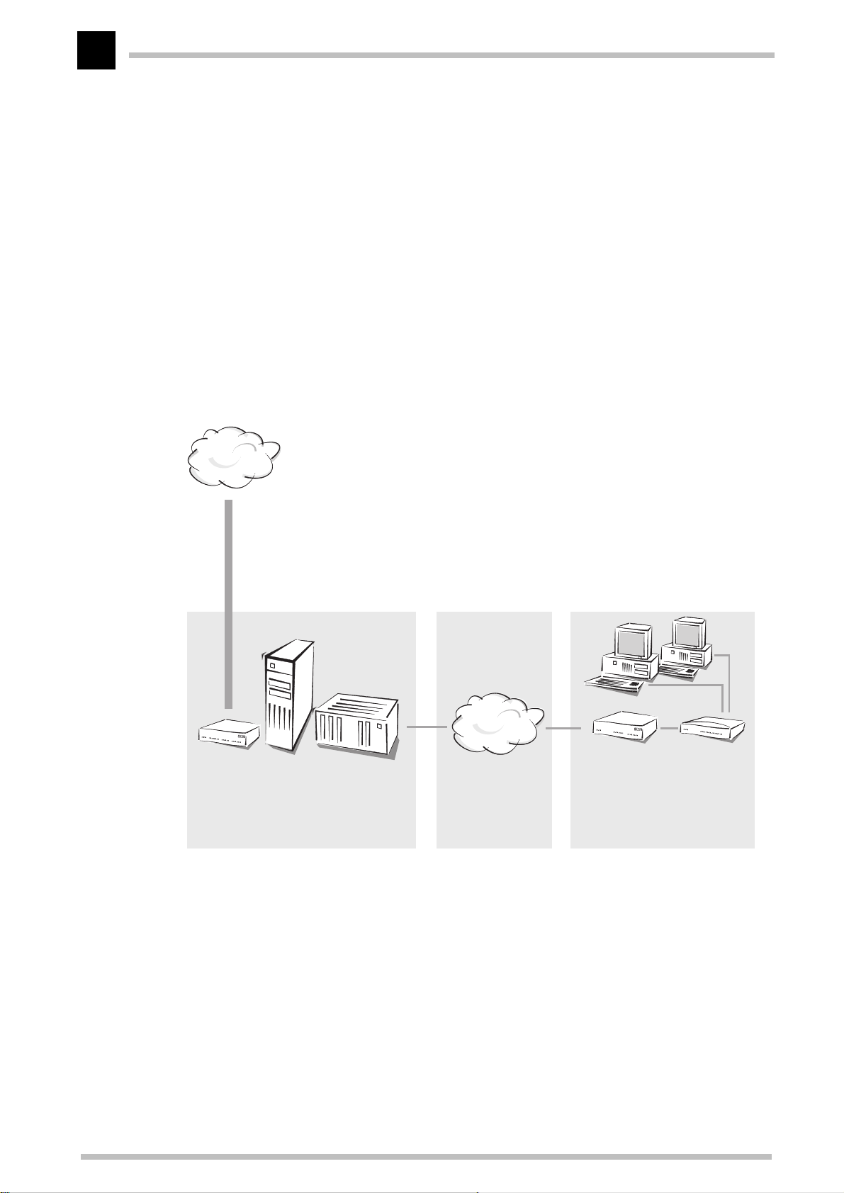
Technical basics
p
48
computer. On the other side is the operator of the broadband cable network who would
like to provide more than just radio and TV.
A headend can accommodate up to 2000 individual users with cable modems like the
ELSA MicroLink Cable
. The headend functions as a multiport, however, giving every user
access to the cable network at any time. Unlike access through analog or ISDN modems,
there are no connection attempts that could fail because all of the provider's ports are
already in use. No further hardware is needed for the connection between the Internet
user and the network operator as long as both the cable modem and the headend use the
bidirectional MCNS standard.
On the other side, the network operator has to establish a connection to the Internet. He
can either act as an Internet service provider (ISP) himself and directly establish access
to the Internet, or he can outsource this task on to another ISP or an online service.
Internet
Backbone
Server with
DHCP
Network of the cable network
o
erator
Headend
MCNS
Cable TV network
Computer workstation in
LAN
ELSA MicroLink
Cable
Network of the user
Hub
This connection to the backbone is of little relevance to the user. However, the greater
the performance of the network operator's backbone line, the quicker the users receive
information from the Internet.
Registration in the cable network
In comparison to other data transfer media, the cable TV network has a very high
bandwidth at its disposal—thus the term broadband cable network. The full bandwidth
is divided up into a variety of channels that are reserved for the transmission of different
kinds of information. You know this from television, where you also find different
ELSA MicroLink Cable
Page 57

Technical basics
49
programs on their respective channels. Specific channels are also set up for the
transmission of Internet content.
Synchronizing
Finding a
channel in the
broadband
network
Registration
Exchange of
administration
information
between headend and cable
modem
After being switched on, the cable modem searches the entire frequency band for a
channel used by the provider to send information from the Internet. Because the
bandwidth is so great, the first time the log-on procedure might take a while. As soon
as the corresponding channel is found, the Sync LED on the
ELSA MicroLink Cable
flashes. The next time the cable modem is switched on, it will first look for the channel
it found the previous time, and thus find the wanted information at a substantially faster
rate. However, if the cable modem is used on another connection, it may have to search
the entire frequency band again.
To speed up the search, providers can preset the
ELSA MicroLink Cable
to search the
particular frequency bands that they normally use.
Do not change these settings yourself without consulting your provider.
When a channel for communication with the provider has been found, the headend gives
a set of instructions to the cable modem that is important to the operation in the cable
network. This process is called registration. It includes:
K The confirmation of the found channel or the transfer to another channel
K The allocation of an IP address that is valid in the cable network, along with a
suitable netmask
K Information on the provider’s server addresses
K The current time
After the registration is completed successfully, the Reg’d LED on the
Cable
lights up and the cable modem is ready to access the Internet.
ELSA MicroLink
ELSA MicroLink Cable
Page 58

Technical basics
50
Network technology
This section will give you a brief introduction to the basics of network technology. These
descriptions do not cover all possible techniques, processes and terms associated with
network technology. They only cover the topic to the degree necessary to provide an
understanding of the product information.
The network and its components
Network,
transmission
medium,
interfaces
Packets
Cells
Host
Router
Whenever several computers communicate with one another, this connection is called a
network. For computers to be able to communicate, they need a physical medium
through which the information can be transmitted. This can be a cable or radio link, for
example, that is connected to the computers using special interfaces (e.g. network
adapters).
The term network cable (or simply cable) in the following text also refers to any other
physical medium that can take on the function of the cable, such as wireless links.
The individual bits of electronic information that are sent from one computer to another
through a medium are called packets or cells, depending on the process.
For most of the following explanations, the difference between packets and cells is
irrelevant. Therefore, we will use the term packet or data packet in a general sense and
only detail the special characteristics of cells as necessary.
The computer and other terminal devices (e.g. the printer) in a network that generate or
process information are called hosts. Ideally, a host is not responsible for the task of
forwarding information. A host normally has exactly one interface to the network.
The transport of packets between two hosts occurs indirectly through exchanges that
pass packets on to the target computer. These exchanges are called routers. A router
has at least two interfaces so that it can receive the data from a sender and pass them
on to a recipient. Apart from the exchange function, the router also has the properties of
a host so that it can also be the recipient of data packets, for configuration purposes for
example.
Connection modes
Point-to-point
connection
ELSA MicroLink Cable
The connection of exactly two hosts via a medium is called a “point-to-point connection”.
In this case a host sends packets that can only be received by
(unambiguous connection).
one
specific recipient
Page 59
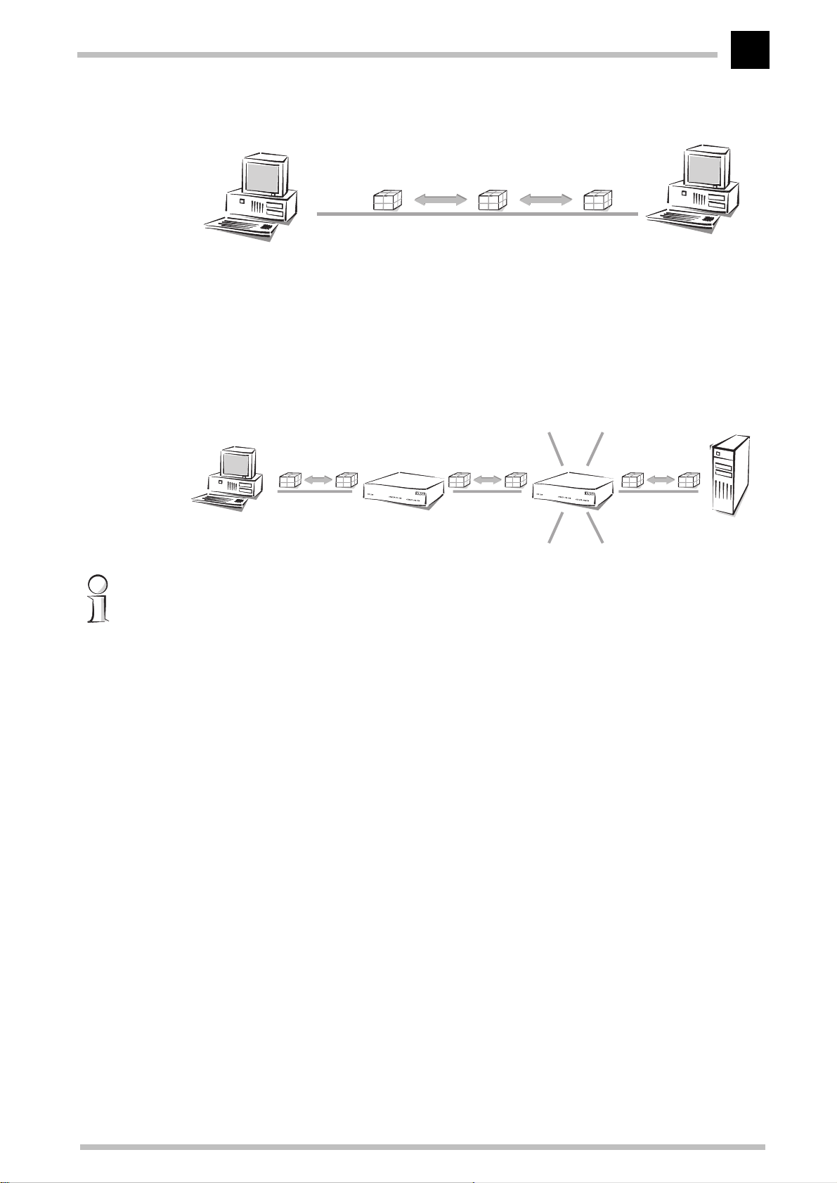
Technical basics
Host Host
Data packet
Medium
51
Access to the Internet is also established through point-to-point connections. Even
though the data packets are sent from the host at the Internet user to the host at the
Internet provider (server) via several routers, every data packet still has its own specific
destination. Furthermore, the routers will only forward the data packets to one recipient.
That's why we also call this connection unambiguous.
Connections to other
Host Host
Router
routers
Point-tomultipoint
connection
Internet user Web server
Strictly speaking, the term “point-to-point connection” is not quite correct. For our
purposes though, it is sufficient to distinguish this kind of connection from the following
“point-to-multipoint connections”.
Generally speaking, it would be uneconomical to directly connect all computers in a
network via point-to-point connection cables, as the computers would then require
multiple interfaces. Computers in a network are therefore plugged into a joint medium
shared by all hosts. The sender simply sends its packet with instructions concerning the
recipient to the medium to which other hosts are connected. The data packet arrives at
every host in the network. Each host then decides whether it is the recipient of the
packet or not. If the packet is addressed to the corresponding host, it will then accept it.
If not, the host will ignore (reject) it. This is a“point-to-multipoint connection”, since we
are not dealing with an unambiguous connection.
ELSA MicroLink Cable
Page 60
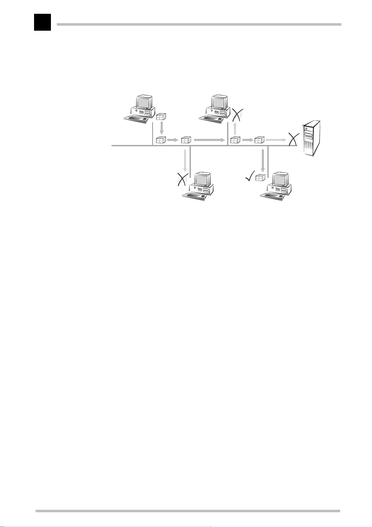
Technical basics
52
Host:
Sender
Data packet
with recipient
information
Host
Host
Host:
Recipient
Protocol
TCP/IP
IP network
Internetwork
Internet
Local network
(LAN)
Kinds of networks
An important prerequisite for communications between computers is a common
language among the hosts. In the world of network technology this language is
called“network protocol” or simply“protocol”.
The most broadly distributed network protocol is the TCP/IP (Transmission Control
P
rotocol/Internet Protocol). It is used mainly in the Internet, but nowadays more and
more company networks use it. Examples of other network protocols are IPX or Apple
Talk. Because of its wide use, this chapter deals mainly with the TCP/IP.
All hosts wanting to communicate using the TCP/IP protocol have to be plugged into the
same network and have to have the TCP/IP protocol (also known as TCP/IP stack)
installed. Such a network is referred to as an IP network.
The connection of multiple networks based on the IP protocol is referred to as an
internetwork. The largest union of many small, public IP networks is the Internet.
A network covering a limited area with hosts on the same hierarchical level and using
the same medium (shared medium) is called a local network (Local Area Network, LAN).
IP addressing
Packet-oriented
transfer
ELSA MicroLink Cable
In IP networks the communication between computers takes place in a packet-oriented
fashion. This means that data or messages are packed together in packets of variable
length and are as such sent from the source computer to the target computer. Apart from
Page 61
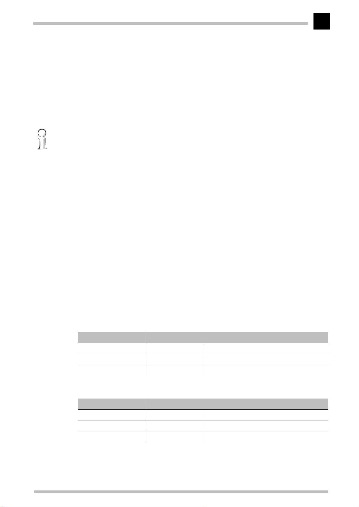
Technical basics
53
the actual information to be transmitted (useful data), the data packet also contains
address and control information.
IP address
Network
address
Netmask
IP addresses are used in IP networks for communications between various devices. In
this case, every host has its own unique address by which it can be identified
unambiguously. What does an IP address look like? It consists of four bytes separated
by dots, making a total of 32 bits. Each of the four bytes can take on values from 0 to
255, e.g. 192.168.130.124.
To be precise, the IP address refers to the interface, and not the host itself. A terminal
device with more than one interface (such as a router) has to have an IP address at its
disposal for every single interface. This is why ISDN routers from ELSA for example,
have an IP address for communication with the hosts in their own network, as well as a
second IP address for communication with the “outside world” using the ISDN. In the
same way, ELSA cable modems have an IP address for their own network and another IP
address for the exchange of data with the cable network.
An IP address contains the address of the network as well as that of the host. The
network address is the same for all hosts on one network, whereas the address of the
host is exclusive and unique to the network. A router, for example, can have more than
one IP address, each one unique to the network.
How then can you differentiate between the part that determines the network and the
part that identifies the host? With the netmask. You know what masks are: they cover
up one part of something and only allow a different part to be visible. This is exactly how
a netmask operates. It is a number which is identical in structure to the IP address, i.e.
32 zeros or ones. The netmask usually starts with ones at the beginning and ends with
zeros. The zeros at the end thus cover the part of the IP address which does not belong
to the network address.
Examples:
This address... ...in bytes... ...looks like this in bits:
IP address 192.168.120.253 11000000.10101000.01111000.11111101
Netmask 255.255.255.0 11111111.11111111.11111111.00000000
Network address 192.168.120.0 11000000.10101000.01111000.00000000
The same IP address, this time with another netmask:
This address... ...in bytes... ...looks like this in bits:
IP address 192.168.120.253 11000000.10101000.01111000.11111101
Netmask 255.255.0.0 11111111.11111111.00000000.00000000
Network address 192.168.0.0 11000000.10101000.00000000.00000000
You can see from this that an IP address alone is not enough. A host can only be
identified unambiguously in combination with a netmask.
ELSA MicroLink Cable
Page 62

Technical basics
54
And you can also see that there are more bits available to identify the individual hosts in
a connected network if there are fewer bits in a netmask that contain a one. While only
254 different addresses could be allocated in the first example with the netmask
255.255.255.0, the second example has as many as 254x254 = 64516 different addresses
available! The first and the last digit of an address space are reserved for the network
address and the broadcast address (addresses for packets to all hosts in an IP network).
In the netmask 255.255.255.0 this is the '0' for the network address and the '255' for the
broadcast address.
A new notation of the netmask simply attaches the number of bits available for the
network address to the IP address: 137.226.4.101/24. The number after the slash tells
us that the first 24 bits indicate the network address. This notation reduces the length
of the entries in the routing tables.
IP address
management
Private address
spaces
The IP addresses must be unique within a specific network in order to avoid confusion.
Since the Internet is based on TCP/IP and thus uses IP addresses for its millions of
connected computers, all Internet addresses must also be unique. Bodies exist that
manage and distribute these publicly-accessible addresses. Since the number of IP
addresses theoretically available is limited, these distributing bodies charge high rates
for the addresses.
A range of IP addresses are reserved for use free of charge (private address spaces) so
that companies do not have to purchase individual IP addresses for every workstation. In
a closed network, these addresses can be used as desired, in a private network or
company, for example. The same address can be used in other closed networks (e.g. in
different companies), but the addresses within one network must be unique.
However, these reserved IP addresses must not be made public (on the Internet). Only
those devices in a network that are connected to a public network (e.g. the router at the
interface to the Internet) must have a registered IP address.
The allocation of IP addresses by the IANA (Internet Assigned Numbers Authority)
permits the following address ranges to be used for private use:
IP address Netmask Remark
10.0.0.0 255.0.0.0 “10” networks: All IP addresses beginning with 10. and whose mask
172.16.0.0 255.240.0.0 All IP addresses beginning with 172.16.–172.31. which are associ-
192.168.0.0 255.255.0.0 All IP addresses beginning with 192.168. and whose mask begins
224.0.0.0 224.0.0.0 All IP addresses beginning with a 224 which are associated with a
ELSA MicroLink Cable
begins with 255. belong to the address range reserved for private
use.
ated with a net mask greater than or equal to 255.240.0.0 are within
the address range reserved for private networks.
with 255.255. belong to the address range reserved for private use.
net mask also beginning with 224 are within the reserved address
range.
This range is reserved for broadcasting purposes and should not be
used for private networks.
Page 63

Technical basics
55
There are two considerations when using these IP addresses:
K The IP addresses used in a private network should not leave this network, i.e. an
Internet connection is only possible when using IP masquerading, for example.
K The packets for these IP addresses will not be routed in the Internet, i.e. backbone
routers will simply reject such IP packets. Depending on the provider, serious
consequences may result if such IP packets are released on the Internet.
IP routing and hierarchical IP addressing
Routing
Routing-table
Hierarchical IP
addresses
Every IP packet contains the IP addresses of the source and of the recipient. A router
receives IP packets at its interface, interprets the destination address and passes the
packets on to those interfaces that are nearest to the recipient. Finding the appropriate
path is called routing.
Every router manages a table (routing table). This table indicates the quickest interface
connection to the host for every host in the network. You can imagine that, as they grow,
these tables may exceed the capacity of the router—the Internet, as a worldwide linking
up of publicly accessible IP computers contains several millions of hosts.
For this reason, hierarchical IP addresses were introduced. This means dividing the IP
network into subnets in which IP addresses are appointed from a coherent numerical
range. It is possible to establish several hierarchy levels, so that different subnets can
be merged. The principle is similar to the hierarchical address used by paper mail,
consisting of a country, a city, a street and a number.
The consequences of this hierarchical IP addressing:
K Since all hosts within one network have the same network address, the host
address is sufficient for the hosts within this network to communicate with one
another.
K A router has to know both the addresses of the hosts that are directly connected to
it, and the addresses of all networks and subnets that are reachable via adjacent
routers.
K It is
not
necessary for a router to know
all
other possible IP addresses.
ELSA MicroLink Cable
Page 64
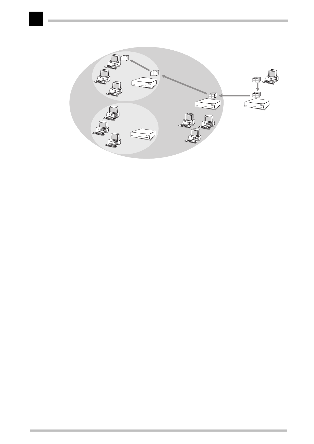
Technical basics
56
Host 'Smith'
External host
Marketing
Superordinate
network:
Example Inc.
Development
Example
Inc.'s router
External router as a
connection to other networks
As an example, think of a company with one large network, in which the different
divisions are incorporated as small subnets. The address of the network for the
marketing division is made up hierarchically from the address of the company and that of
the department.
Whenever a host external to the company network sends a packet to a host in the
Example Inc., this is what happens:
a The sender gives the packet the destination address “host 'Smith' – Marketing –
Example Inc.”.
b All an external router that establishes the connections to other networks has to
know is how to reach Example Inc. As soon as it receives a packet with the address
for Example Inc., it passes the packet on to the router responsible for Example Inc.
c The router at Example Inc. receives the packet and extracts from the address the
information that it is directed at Example Inc. Since it is itself part of Example Inc.,
it takes a closer look at the address to find the name of the division. It then passes
the packet on to the router in the marketing division.
d The router in the marketing division receives the packet and extracts from the
address the information that it is directed at the marketing division of Example Inc.
Since it is itself part of this division, it takes a closer look at the address to find the
name of the host. It then passes the packet on to the host of the employee Sam
'Smith'.
Now we shall take a look at the example using proper IP addresses instead of symbolic
names. The network of Example Inc. has the numerical space '192.168.100.0' to
'192.168.100.255' at its disposal, with the '0' for the network address and the '255' for
the sender address.
ELSA MicroLink Cable
Page 65

Technical basics
57
All the router has to remember is that every address beginning with '192.168.100' is
located within the network of Example Inc.
Now imagine a router that is connected to the network of Example Inc. through an
interface. If it receives a packet with destination address '192.168.100.4' and netmask
'255.255.255.0', it will compare this with every network address it knows. In doing so it
carries out a logical AND with the netmask, and compares the results with the network
address: '192.168.100.4' AND '255.255.255.0' is '192.168.100.0'. This is the network
address of the Example Inc. network. The router recognizes that the recipient is located
within Example Inc. and passes the packet on to the appropriate interface for Example
Inc. Within Example Inc. the packet is then passed on to the appropriate subnet.
The same procedure is used for the transfer of IP packets within a network:
a If a host in the subnet of the development department wants to send a data packet
to Mr. 'Smith', the sender attaches the destination address "Host 'Smith' –
Marketing – Example Inc.".
Media access
control
b The router in the development division receives the packet and extracts from the
address the information that it is directed at the marketing division of Example Inc.
Since it is itself part of Example Inc., but not of the marketing division, it passes the
packet on to the router in the superordinate network.
c The router at the Example Inc. receives the packet and extracts from the address the
information that it is directed at Example Inc. Since it is itself part of Example Inc.,
it takes a closer look at the address to find the name of the division. It then passes
the packet on to the router in the marketing division, where the packet is passed on
to the recipient.
Expansion through local networks
Up to now we have only considered the point-to-point connections. However, many
computer networks are based on multipoint cabling such as Ethernet. All computers
connected to the same network can then receive the signals of all other computers (socalled broadcast transfer to a shared medium). If several computers are sending
simultaneously, the superimposed signals are destroyed. A variety of access methods
such as CSMA/CD or Token Ring are implemented in the MAC layer (Media Access
C
ontrol, MAC) for the avoidance and resolution of such collisions.
LAN and IP
network
The connection of all computers communicating through a shared medium using a MAC
protocol is called a LAN. A LAN forms an independent network and is subordinate to the
IP network, i.e. IP networks can use the physical connections of the LAN to establish
connections between the hosts and the routers. LAN refers to a limitation of the area
covered by the network, not a restriction of the number of workstations connected to it.
ELSA MicroLink Cable
Page 66
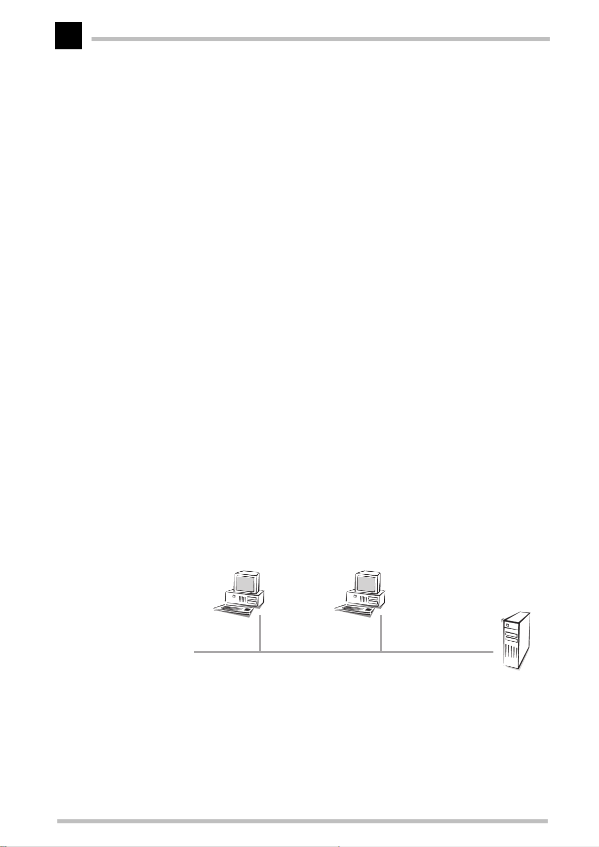
Technical basics
58
MAC address
IP in the LAN
Specific LAN addresses hardwired into the interfaces by their manufacturers are used to
manage the transfer in the LAN. Since the LAN addresses are used for communication
via the MAC protocol, they are called MAC addresses. They can be thought of as the
fingerprint of the interface hardware. MAC addresses can look like this, for example: 0080-C7-6D-A4-6E.
MAC addresses are independent of IP addresses. An IP host whose interface works
through a LAN has an IP and a MAC address. Whereas the structure of IP addresses with
its similarity to postal addresses is supposed to simplify routing in enormous IP networks,
the fingerprint-like MAC addresses are designed to make the connection to a LAN as
easy as possible.
Transfer in LAN is also packet-oriented. Every MAC packet contains the MAC addresses
of the source and of the recipient. Although every packet is received by all computers, it
is processed only by the target computer. There is an additional MAC broadcast address
that is processed by all computers in the LAN.
Every LAN packet contains an entry with the type of the network protocol. An IP packet
can be transferred through a LAN by packing it in a LAN packet and adding the 'IP'
protocol type to it. Because of the IP entry, the LAN interface at the receiving host
recognizes that the LAN packet contains an IP packet, extracts it and processes it as an
ordinary IP packet. In this way, IP packets and packets of other network protocols like
IPX can be transferred simultaneously through the same LAN without conflicts (this is
why a LAN is called multiprotocol-capable).
To an IP host, a LAN behaves as if it were an independent network with a router. The
hosts gives the packets to the LAN which handles the further distribution of the data
packets. This is why only IP addresses from the numerical space of the specific network
should be used for the internal communication of the hosts in a LAN through the IP
protocol.
IP host
in the LAN
LAN with router function:
distributes the LAN packets
IP host
in the LAN
IP host
in the
LAN
To a router in the LAN, a host in its own LAN seems to be located behind another router.
So the task for the router is very simple: all it has to know for operating in the IP network
are the IP addresses
K of the directly connected hosts and
K of the available networks and subnets,
ELSA MicroLink Cable
Page 67
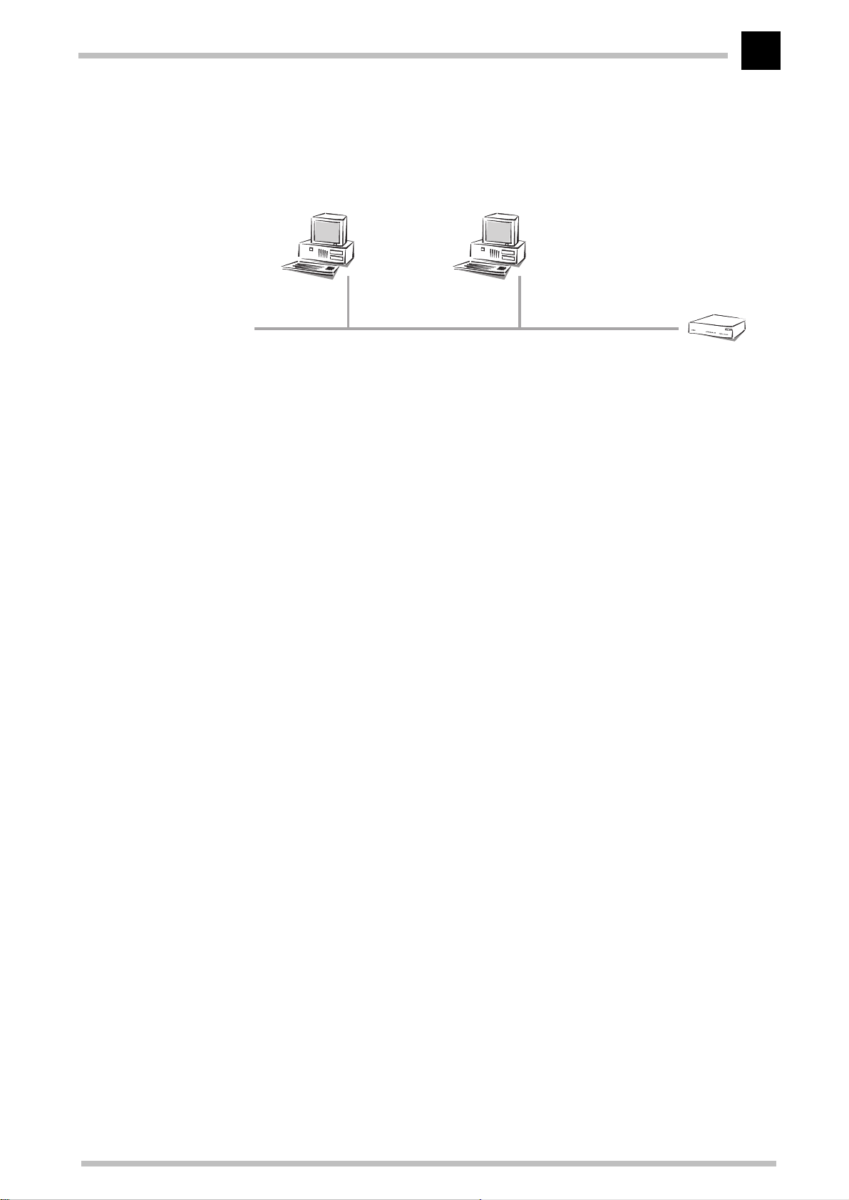
Technical basics
59
i.e. all it has to remember is the network address and the netmask of the subnet in the
LAN.
IP host
in the LAN
LAN with router function
IP host
in the LAN
The router in the
LAN:
knows only the
address of the LAN
In contrast, the host is confronted with a more difficult task than the router. In case of
an interface with a point-to-point cable, the host knows that all packets that it sends
through the interface automatically arrive at its router, for example. In case of the pointto-multipoint connection to the LAN, it has to distinguish two cases, however.
K A packet with an address outside the LAN is passed on to a router in the LAN that
takes care of the further processing of the packet.
K The sending host must send a packet with an address within the LAN directly to the
target host, since the router in the network does not know the addresses of all the
different hosts.
Data transfer within the LAN
Let's use an example to explain this. Imagine the hosts of the subnet in the marketing
division are linked via a LAN. The hosts have IP addresses from the numerical space
'137.226.4.1' to '137.226.4.254' (the addresses '137.226.4.0' and '137.226.4.255' are
reserved), the network address is '137.226.4.0' and the netmask is '255.255.255.0'. A
router connected to the LAN provides access to the wide world of the Internet. Its LAN
interface has the IP address '137.226.4.1' and the MAC address '00-80-C7-6D-A4-6E'.
Imagine wanting to send an IP packet from host 'Smith' (with IP address '137.226.4.10'
and MAC address '00-10-5A-31-20-DF') to host 'Miller' (with IP address '137.226.4.20'
and MAC address '00-10-5A-31-20-EB'). Using the network address and the netmask,
host 'Smith' recognizes that host 'Miller' is located in the own network. It therefore has
to send the packet through the LAN, directly to host 'Miller'. Unfortunately the LAN
interface cannot say: “Send the IP packet to IP address 137.226.4.20”, because the LAN
interface only understands MAC addresses.
This is why every host has to manage a table that translates IP addresses to MAC
addresses. But how do the entries end up in the table? They could be entered manually,
but that would not satisfy the objective of making the connection of a new computer to
the LAN as easy as possible.
ARP
Therefore the LAN has a special mechanism that automates this process: the Address
Resolution Protocol, ARP. The table itself is called the ARP table. Whenever a host does
ELSA MicroLink Cable
Page 68
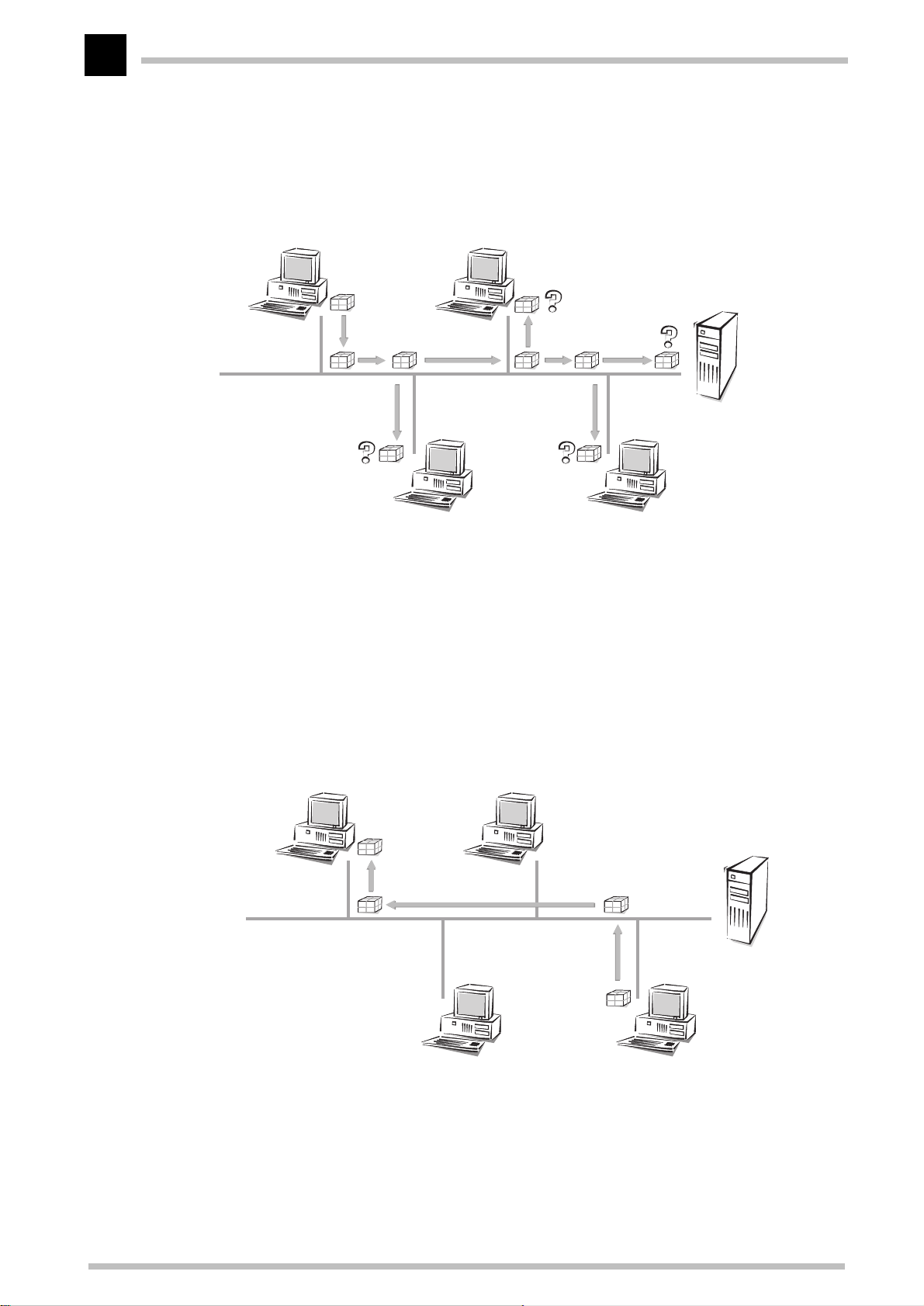
Technical basics
60
not find an entry in the table for a particular IP address (in our example '137.226.4.20'), it
sends an ARP request packet to all hosts in the LAN (with the LAN broadcast address as
a target address).
Host 'Smith'
ARP request to
'137.226.4.20'
Host 'Miller'
This ARP request packet is simply a question to all hosts listening to the IP address
'137.226.4.20'. Host 'Miller' receives the packet, feels addressed and answers with an
ARP response packet that it sends directly to host 'Smith' (the MAC address '00-10-5A31-20-DF' of host 'Smith' is extracted from the sender field in the ARP request packet).
Host 'Smith' recognizes this as an answer to its request, extracts the MAC address '0010-5A-31-20-EB' from the ARP response packet and enters it into its ARP table.
Host 'Smith'
Host 'Miller'
ARP response
'137.226.4.20' =
'00-10-5A-31-20-EB'
Then it can finally turn to its original task: sending the IP packet to host 'Miller'. It now
finds the entry “IP address 137.226.4.20 corresponding to MAC address '00-10-5A-31-20-
ELSA MicroLink Cable
Page 69

Technical basics
EB'” in the ARP table and tells its LAN interface: “Send this IP packet to the computer
with the MAC address '00-10-5A-31-20-EB'”.
Data transfer from the LAN onto the Internet
Imagine the second task, sending an IP packet from host 'Smith' to the remote host
'External' with IP address 151.189.12.43. Host 'Smith' compares the IP address with its
network address and realizes that host 'External' is located outside the LAN. So host
'External' can only be reached through the router. Host 'Smith' finds out the MAC
address of the router '00-80-C7-6D-A4-6E' by looking up the router’s IP address in the
ARP table (if necessary another ARP request is made). So host 'Smith' tells its LAN
interface: “Send this IP packet to the computer with the LAN address '00-80-C7-6D-A46E'”. The router extracts the IP packet from the LAN packet and finds out about the IP
address of host 'External'. In the routing table the router then looks for the network
address of this host and thus finds the interface through which to pass on the IP packet.
61
LAN coupling on MAC basis
You know how LANs simplify the connection of computers to a local network. Nearly all
house networks are thus LAN based. In some cases a LAN is covers such a large area
that the physical characteristics of the cable prohibit the connection of any more
computers. This results in the necessity to couple up several LANs in such a way that
electrically and in terms of the MAC protocol they act as independent LANs, but for the
IP protocol look like one big LAN.
This coupling of LANs is carried out using bridges. A bridge works somewhat like a
router, but uses only MAC addresses for routing, not IP addresses. Since MAC addresses
do not give any information on the structure of the network the way IP addresses do,
every bridge has to know all MAC addresses in the entire LAN.
And so we encounter the same problem that we had with the routers before the
introduction of subnets: As the LAN expands, it will at some point exceed the capacity of
the address tables of the bridges. So one cannot use bridges to connect an infinite
number of LANs. On the other hand, the unstructured MAC addresses allow the bridges
to learn automatically about the location of computers in the network, using the received
packets. This is called an “intelligent bridge”.
ELSA MicroLink Cable
Page 70

Technical basics
62
ELSA MicroLink Cable
Page 71

Appendix
Technical data
Appendix
63
Technical data
LAN interface Ethernet IEEE 802.3, 10Base-T (Twisted Pair, RJ45, Node/Hub switch)
Cable TV interface MCNS DOCSIS (ITU-T J.112, physical layer as per Annex A & Annex B, MAC as per Annex B)
ELSA MicroLink Cable
Socket: F –socket (IEC169-2 connection via included adapter)
Reception frequency band: 88 - 860 MHz
Reception channel width: 6 MHz or 8 MHz
Receiver level: 48 W – 78 dBµV
Receiver modulation: 64QAM, 256QAM
Receiver data rate: 30.34 Mbps (64QAM), 42.88 Mbps (256QAM)
S/N ratio in receive direction: > 21 dB (64 QAM)
> 28 dB (256 QAM)
Transmission frequency band: 5 – 42 MHz (5 – 65 MHz optional)
Transmission channel width: 200 – 3200 kHz
Transmission level: 85 – 122 dBµV
Transmission modulation: QPSK, 16QAM
Transmission data rate: 0,32 – 5,12Mbps (QPSK), 0,64 – 10,24Mbps (16QAM)
S/N ratio in transmit direction: > 14 dB (Burst QPSK)
> 20 dB (Burst 16QAM)
Network protocols Bridge mode: Bridging of all IEEE 802.3-based protocols
IP router: IP, TCP, ICMP, ARP, RIP-1, RIP-2, PROXY ARP, DHCP
Filter possibilities Bridge mode: Broadcast, multicast, destination MAC address,
source MAC address, automatic filtering of local and
remote stations
IP router TCP, UDP port filtering, source and destination net-
work filter
IP masquerading
(NAT/PAT)
Management Cable network operator: Via SNMP and TFTP (transfer of configuration files and
Display/operation LEDs for LAN and cable TV network status, factory-default button, reset button
Power supply 12VAC with AC adapter for 230 V (US version: 110V), 10 VA
Ambient conditions Temperature: 5 - 40°C, humidity: 0 - 80%, non-condensing
Dimensions and
design
Internet access using a single IP address via IP address and port implementation, static/
dynamic IP address assignment via DHCP, masking of TCP, UDP, ICMP and FT P; DNS forwarding; inverse masquerading for intranet IP services
firmware updates)
User: Via the cable TV network or LAN with TCP/IP, pass-
word protection,
Rugged metal case, LEDs on front panel, connections on rear panel;
Dimensions: 158 x 32 x 135 mm (W x H x D)
ELSA LANconfig
, SNMP, TFTP, telnet
ELSA MicroLink Cable
Page 72
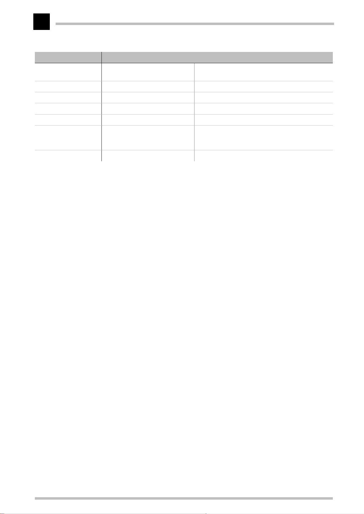
64
Appendix
Technical data
Package contents Accessories: AC adapter , F-to-IEC169-2 adapter, connector cable for
Service Warranty: 6 years
ELSA MicroLink Cable
cable TV network, 10Base-T cable
Software: Configurations software
Documentation: Comprehensive manual and
Installation Guide: German, English, French, Italian, Dutch, Spanish
ELSAcare: In the event of a warranty claim within the first 100
days following the purchase, replacement product will
be provided.
Support: Via hotline and Internet
ELSA LANconfig
ELSA
CD-ROM
, TFTP client
ELSA MicroLink Cable
Page 73

Appendix
65
Warranty conditions
The ELSA AG warranty, valid as of June 01, 1998, is given to purchasers of ELSA products in addition to
the warranty conditions provided by law and in accordance with the following conditions:
1 Warranty coverage
a) The warranty covers the equipment delivered and all its parts. Parts will, at our sole discretion, be
replaced or repaired free of charge if, despite proven proper handling and adherence to the
operating instructions, these parts became defective due to fabrication and/or material defects.
Also we reserve the right to replace the defective product by a successor product or repay the
original purchase price to the buyer in exchange for the defective product. Operating manuals and
any supplied software are excluded from the warranty.
b) Material and service charges shall be covered by us, but not shipping and handling costs involved
in transport from the buyer to the service station and/or to us.
c) Replaced parts become property of ELSA.
d) ELSA are authorized to carry out technical changes (e.g. firmware updates) beyond repair and
replacement of defective parts in order to bring the equipment up to the current technical state.
This does not result in any additional charges for the customer. A legal claim to this service does
not exist.
2 Warranty period
The warranty period for ELSA products is six years. Excepted from this warranty period are ELSA color
monitors and ELSA videoconferencing systems with a warranty period of 3 years. This period begins at
the day of delivery from the ELSA dealer. Warranty services do not result in an extension of the warranty
period nor do they initiate a new warranty period. The warranty period for installed replacement parts
ends with the warranty period of the device as a whole.
3 Warranty procedure
a) If defects appear during the warranty period, the warranty claims must be made immediately, at
the latest within a period of 7 days.
b) In the case of any externally visible damage arising from transport (e.g. damage to the housing), the
transport company representative and ELSA should be informed immediately. On discovery of
damage which is not externally visible, the transport company and ELSA are to be immediately
informed in writing, at the latest within 7 days of delivery.
c) Transport to and from the location where the warranty claim is accepted and/or the repaired device
is exchanged, is at the purchaser's own risk and cost.
d) Warranty claims are only valid if the original purchase receipt is returned with the device.
4 Suspension of the warranty
All warranty claims will be deemed invalid
a) if the device is damaged or destroyed as a result of acts of nature or by environmental influences
(moisture, electric shock, dust, etc.),
b) if the device was stored or operated under conditions not in compliance with the technical
specifications,
ELSA MicroLink Cable
Page 74

66
Appendix
c) if the damage occurred due to incorrect handling, especially to non-observance of the system
description and the operating instructions,
d) if the device was opened, repaired or modified by persons not authorized by ELSA,
e) if the device shows any kind of mechanical damage,
f) if in the case of an ELSA Monitor, damage to the cathode ray tube (CRT) has been caused especially
by mechanical load (e.g. from shock to the pitch mask assembly or damage to the glass tube), by
strong magnetic fields near the CRT (colored dots on the screen), or through the permanent display
of an unchanging image (phosphor burnt),
g) if, and in as far as, the luminance of the TFT panel backlighting gradually decreases with time, or
h) if the warranty claim has not been reported in accordance with 3a) or 3b).
5 Operating mistakes
If it becomes apparent that the reported malfunction of the device has been caused by unsuitable
software, hardware, installation or operation, ELSA reserves the right to charge the purchaser for the
resulting testing costs.
6 Additional regulations
a) The above conditions define the complete scope of ELSA’s legal liability.
b) The warranty gives no entitlement to additional claims, such as any refund in full or in part.
Compensation claims, regardless of the legal basis, are excluded. This does not apply if e.g. injury
to persons or damage to private property are specifically covered by the product liability law, or in
cases of intentional act or culpable negligence.
c) Claims for compensation of lost profits, indirect or consequential detriments, are excluded.
d) ELSA is not liable for lost data or retrieval of lost data in cases of slight and ordinary negligence.
e) In the case that the intentional or culpable negligence of ELSA employees has caused a loss of data,
ELSA will be liable for those costs typical to the recovery of data where periodic security data back-
ups have been made.
f) The warranty is valid only for the first purchaser and is not transferable.
g) The court of jurisdiction is located in Aachen, Germany in the case that the purchaser is a merchant.
If the purchaser does not have a court of jurisdiction in the Federal Republic of Germany or if he
moves his domicile out of Germany after conclusion of the contract, ELSA’s court of jurisdiction
applies. This is also applicable if the purchaser's domicile is not known at the time of institution of
proceedings.
h) The law of the Federal Republic of Germany is applicable. The UN commercial law does not apply
to dealings between ELSA and the purchaser.
ELSA MicroLink Cable
Page 75

Declaration of conformity
KONFORMITÄTSERKLÄRUNG
DECLARATION OF CONFORMITY
Diese Erklärung gilt für folgendes Erzeugnis:
This declaration is valid for the following product:
Geräteart: Modem
Type of Device:
Typenbezeichnung:
Product Name:
MicroLinkTM Cable
Appendix
67
Hiermit wird bestätigt, daß das Erzeugnis den folgenden Schutzanforderungen entspricht:
This is to confirm that this product meets all essential protection requirements relating to the
Niederspannungs Richtlinie (73/23/EWG)
Low Voltage Directive (73/23/EEC)
EMV Richtlinie (89/336/EWG)
EMC Directive (89/336/EEC)
Zur Beurteilung der Konformität wurden folgende
The assessment of this product has been based on the following
EN 50082-1: 1992 Teile/
EN 50081-1: 1992 Teile/
.
Normen
Parts
: EN61000-4-2,3,4,6,11
Parts
: EN 55022B+A1: 1995 +A2: 1997
herangezogen:
standards
EN 60950: 1992+ A1: 1993 +A2: 1993 +A3: 1995 +A4: 1997 +A11: 1997
Diese Erklärung wird verantwortlich für den Hersteller / Importeur
On behalf of the manufacturer / importer
ELSA AG
Sonnenweg 11
D-52070 Aachen
abgegeben durch
this declaration is submitted by
Aachen, 19. Juli 1999
Aachen, July 19th 1999
i.V. Peter Wieninger
Bereichsleiter Entwicklung
VP Engineering
ELSA MicroLink Cable
Page 76

68
Appendix
ELSA MicroLink Cable
Page 77

Index
Index
69
A
K
Access control
Access protocols
Access time
Access-list
Address Administration
Address administration
Address pool
Address ranges
Apple Talk
ARP cache
ARP table
ARP-aging-minute(s)
Auto mode
B
K
Barring
..........................................................30
Boot system
..............................................30
..........................................57
..................................................90
....................................................93
................................17
................................40
.........................................42, 102
.............................................95
.....................................................52
.....................................................93
......................................................93
.....................................94
..................................................102
................................................106
Bridge
filtering data packets
Bridge
Bridge mode
Bridge table
Broadcast
...........................................................39
.................................................90
..................................................90
......................................................90
Broadcast address
Broadcast data packets
Broadcast transfer
Brute force
C
K
Cable
Cable network
Cache
....................................................................7
CE
Cells
Communities
....................................................29
.............................................................50
..............................................53
............................................................93
..............................................................50
.................................................25
Config-aging-minute(s)
..................................40
........................................54
................................90
........................................57
...............................104
Configuration
Commands
SNMP
Configuration options
...................................................19
..........................................................24
.................................103
D
K
Data packet
Default route
Destination addresses
Destination network
Destination port
DHCP
DHCP client
DHCP server
Display elements
Distance of a route
........................................................38, 93
DNS
DNS Forwarding
DNS server
Domain Name Service
Dst-address
Dst-netmask
..................................................50
................................................95
..................................91
.....................................95
..........................................100
.....................................................40, 101
...................................................41
....................................17, 41, 101
............................................1
.......................................33
...........................................38
.............................................40, 43
..................................38
................................................100
...............................................100
Dynamic Host Configuration Protocol
Dynamic IP routing table
Dynamic routing
E
K
Encryption
End address
...........................................32
.....................................................30
..................................................42
End-address-pool
Exclusion routes
F
K
..................................................................7
FCC
..............................................................30
Filter
Filter-table
Filter-type
Firewall function
FirmSafe
...............................................22, 105
Firmware
.....................................................91
.....................................................104
...........................................33
....................................................91
...........................................32
........................................101
..............................97
Firmware Upload
with LANconfig
Firmware upload
using TFTP
Firmware-upload
Flash ROM
...........................................23
...........................................23
...................................................24
........................................104
....................................................22
..........40
ELSA MicroLink Cable
Page 78

Index
70
K G
Gateway
...........................................32, 40, 43
K H
Heap reserve
Hierarchical IP addresses
..............................................................50
Host
Hub
.................................................................4
................................................90
.............................55
K I
.............................................................54
IANA
.......................................................96, 99
ICMP
Inband
Install software
Interface
Internet
Internetwork
Inverse masquerading
IP
IP access list
IP address
IP addresses
IP broadcast
IP header
IP masquerading
IP multicast
IP network
...........................................................17
Requirements
using Telnet
...................................................31, 52
...................................................................96
simple masquerading
supported protocols
..............................................17
.................................................18
............................................22
.......................................................50
.................................................52
..................................98
.................................................17
.........................................17, 32, 92
.................................................53
..................................................97
.......................................................96
.........................30, 31, 36, 98
..................................37
....................................38
...................................................97
.....................................................52
IP routing
............................................................31
Filter
FTP
...............................................................31
Telnet
IP routing table
IP-netmask
IPX
ISDN network
..........................................................31
.......................................32, 95
....................................................92
.................................................................52
...............................................53
K L
.........................................................52, 57
LAN
LAN-Coll
LANconfig
.........................................................3
.........................................17, 18, 23
LAN-filter tab.
Language
LAN-Link
LAN-Rx
LAN-Tx
LED
............................................................3
............................................................3
..................................................................1
Link Status LED
Loc. routing
Local Area Network
local network
Lock-minutes
Login
.......................................................23, 30
Login barring
Log-in block
Login-errors
...............................................96
....................................................104
.........................................................3
...............................................4
...................................................96
......................................52
................................................52
..............................................104
.................................................29
................................................104
................................................104
K M
..............................................................57
MAC
MAC address
MAC addresses
MAC protocol
................................................89
............................................58
...............................................58
Management Information Base
Manager
Masquerading
Masquerading table
Media Access Control
Medium
MIB
Multicast
Multipoint cabling
.......................................................27
........................................92, 98
.....................................99
..................................57
........................................................50
...............................................................25
......................................................90
........................................57
Multiprotocol capability
K N
Name
............................................................ 89
...................................................30, 31, 36
NAT
Netmask
Network
Network adapter
Network address
Network cable
Network connection
.......................................................53
........................................................50
..........................................50
..........................................53
..............................................50
.....................................89
Network Information Center
Network protocol
................................................................36
NIC
..........................................52
...................27
...............................58
........................36
ELSA MicroLink Cable
Page 79

Index
71
Node ...............................................................4
K O
Objects
Online media
Operating
Operating modes
Other
..........................................................25
................................................17
..........................................90, 92, 94
..........................................29
...........................................................106
K P
Packet
Password
Password protection
Password-required
PAT
Period of validity
Physical medium
Point-to-multipoint connection
Point-to-point connection
Port number
PPP negotiation
Private address spaces
Prohibited address ranges
Protocol
Proxy ARP
...........................................................50
......................................................93
.....................................29
.....................................104
...................................................30, 31, 36
.....................................41, 43
...........................................50
.....................51
.............................50
..................................................38
............................................92
.................................54
............................95
.........................................................52
.....................................................95
K R
R1-mask
Registered IP address
Remote station
RIP
RIP-type
Router
Router name
Routing
Routing table
........................................................97
.............................54, 92
.............................................90
.................................................................97
........................................................97
...........................................................50
.................................................33
.........................................................55
................................................55
K S
Security
Serial port
Service table
.............................................29, 30, 32
.....................................................24
.................................................98
Setup
bridge-module
DHCP-module
IP-router-module
.............................................90
............................................101
.........................................94
LAN-module
................................................89
TCP-IP-module
WAN-module
Shared Medium
Single user access
SNMP
...................................................24, 101
Agents
Manager
MIB
.........................................................24
......................................................24
..............................................................25
Source addresses
Source port
Start address
.................................................100
................................................42
Start-address-pool
Static routing
Status
...........................................................75
................................................32
Config-statistics
IP-router-statistics
operating time
Queue-statistics
TCP-IP-statistics
Subnet
..........................................................55
System-administrator
System-location
K T
Table-RIP
TCP
......................................................97
................................................................99
TCP max. connections
TCP/IP
TCP/IP stack
...............................................17, 32, 52
..................................................52
TCP-aging-minute(s)
Technical data
Telnet server
.............................................................. 17
TFTP
TFTP server
..............................................................76
Time
Timeout
TOS
...............................................................96
.................................................93
...................................................93
.......................................................103
Trace
code and parameters
Examples
starting
Trace Outputs
.....................................................22
........................................................21
...............................................21
.............................................91
..............................................89
......................................52, 57
........................................31
.........................................91
......................................101
..........................................88
......................................83
.............................................76
....................................85, 87
..........................................79
.................................101
..........................................101
..................................94
.....................................94
.............................................. 63
..................................21
ELSA MicroLink Cable
Page 80

Index
72
Trap ...............................................................27
Trap-IP
Traps-active
Type-of-service
........................................................101
................................................101
.............................................96
K U
...............................................................99
UDP
Upload
..........................................................22
Upload-system
K V
Version-table
K W
Wireless links
WWW
...........................................................32
............................................106
..............................................105
...............................................50
ELSA MicroLink Cable
Page 81
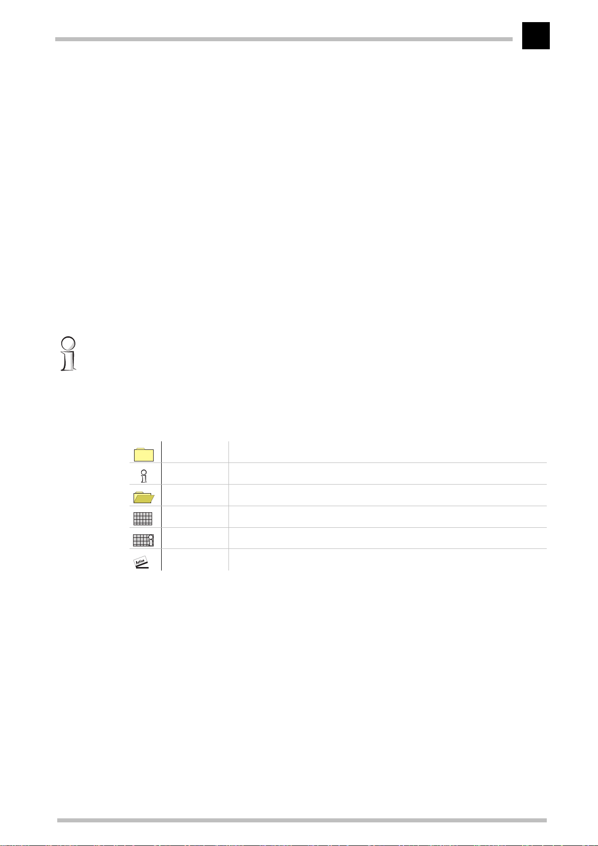
Description of the menu options
Description of the menu options
R73
The menu tree for
information, setup parameters, firmware information and 'other'.
In order to help you familiarize yourself with the system, you will first be given an
overview of the menu structure.
In the complete list of all menu options you will find a detailed description of all displays,
menus and actions along with their associated parameters, default settings and input
options.
You can access the menus when configuring via telnet or terminal programs and via
SNMP (also see 'Configuration Modes').
When configuring with
that gives you brief descriptions of the individual parameters.
ELSA MicroLink Cable
ELSA LANconfig
, you are provided with an integrated help system
configuration is divided up into status
All channel-related statistics and menus in this documentation refer to two channels
only, even if more than two channels are available to the specific devices. Interfacerelated information is also provided for a single interface only. The information is equally
applicable to the additional channels and interfaces.
Symbols
Menu Indicates a further submenu.
Info Indicates a value that cannot be modified.
Value Indicates a value that can be modified.
Table Indicates a table whose entries can be modified.
Info table Indicates a table whose entries cannot be modified.
Action Performs an action.
ELSA MicroLink Cable
Page 82
R74
Description of the menu options
Overview of the menus
Setup
Name
Cable-module
LAN-module
Bridge-module
TCP-IP-module
IP-router-module
SNMP-module
DHCP-server-module
Config-module
SYSLOG-module
Firmware
Version-table
Table-firmsafe
Status
Operating-time
Current-time
Cable-statistics
LAN-statistics
Bridge-statistics
TCP-IP-statistics
IP-router-statistics
Config-statistics
Queue-statistics
MCNS-statistics
Init-status
DHCP-client-status
Output-internal-status messages
Mode-firmsafe
Timeout-firmsafe
Test-firmware
Firmware-upload
Delete-values
Other
Boot-system
Factory-default-system
Upload-system
ELSA MicroLink Cable
Page 83
Description of the menu options
R75
Status
The Status menu contains information on the current status and the internal sequences
of operations in the LAN and in the cable network, which can relate to the data
transmission route (e.g. registration with the headend) or to statistics (e.g. number of
data blocks received and transmitted). The statistics displays are an important aid for
verifying correct operation and optimizing parameter settings. In addition, they provide
valuable information for error analysis when malfunctions occur.
Most status displays are continually updated and can be deleted with a
value
or set to
0 in the current menu.
The menu has the following layout:
Status Running status displays
Operating-time Period of time the device has operated since it was last switched
on
Current-time Current time in device
Cable-statistics Display of statistics related to the cable network
LAN-statistics Displays LAN statistics
Bridge-statistics Bridge area statistics
TCP-IP-statistics Statistics from the TCP/IP area
IP-router-statistics Statistics from the IP router
Config-statistics Remote configuration statistics
Queue-statistics Statistics relating to the packets in the queues of the individual
modules
MCNS-statistics Statistics relating to MCNS packets and MCNS timeouts
Init-status Status of initialization process
DHCP-client-status Status of the DHCP client and the negotiated values
Info-connection Information on the last connection for each interface
Layer-connection Information on the B-channel protocol used for each interface
Channel-statistics Information of the status of the individual channels
Time-statistics Time module information
LCR-statistics Least-cost router information
Output-internal-status
messages
Delete-values Deletes all values except tables with substatistics.
Query of the internal system status messages
ELSA MicroLink Cable
Page 84
R76
Description of the menu options
Status/Operating-time
The operating time of the router since it was last started is displayed here in days, hours,
minutes and seconds.
Status/Current-time
This displays the current device time transferred by the headend.
Status/Cable-statistics
This option allows you to display the various statistics parameters for the cable network
port. A large number of values related to the data volume transferred provide you with
useful information on cable port load, errors that have occurred and the internal
resources of the cable modems that are available in the current operating state.
Status/cable-statistics
The
menu has the following layout:
/Cable-statistics Running status displays
Cable-tx-discarded Number of packets discarded due to an error/lack of
resources
Cable-heap-packets Number of buffers available
Cable-queue-packets Number of buffers in use
Cable-queue-errors Number of packets discarded due to a lack of buffers
Cable-tx-MAC-queue-pak-
kets
Cable-rx-MAC-queue-pak-
kets
Cable-rx-fifo-full Number of receive FIFO overruns
Cable-resp.-bandwidthrequests
Cable-rx-overflows-datapackets
Cable-rx-overflows-Msgpackets
Cable-rx-CRC-mistake-pakkets
Number of buffers to be sent in the MAC chip
Number of buffers for reception in the MAC chip
Number of unanswered bandwidth request packets
Number of packets not received due to a lack of buffers
Number of control packets not received due to a lack of
buffers
Number of control packets incorrectly received
Cable-rx-CRC-mistakeMCNS-header
Cable-tx-data packets Number of data packets sent
Cable-rx-data packets Number of data packets received
Cable-tx-msg-packets Number of control packets sent
Cable-rx-msg-packets Number of control packets received
ELSA MicroLink Cable
Number of MCNS-header incorrectly received
Page 85
Description of the menu options
/Cable-statistics Running status displays
R77
Cable-rx-MCNS-headervalid
Cable-FEC-lock-losts-notrecovered
Cable-FEC-lock-losts-recovered
Cable-TRC-lock-losts-notrecovered
Cable-TRC-lock-losts-recovered
Delete-values Deletes Cable statistics
Number of MCNS headers correctly received
Number of cable FEC lock losses not synchronized
Number of cable FEC lock losses resynchronized
Number of cable TRC lock losses not synchronized
Number of cable TRC lock losses resynchronized
Status/LAN-statistics
Similarly to the previous menu option, this option allows you to display the statistics
relating to the LAN connection. The
layout:
/LAN-statistics Running status displays
Status/LAN-statistics
menu has the following
LAN-rx-packets N umber of data packets received
LAN-tx-packets N umber of data packets sent
LAN-rx-errors Number of data packets incorrectly received
LAN-tx-errors Number of data packets incorrectly sent
LAN-stack-errors Number of packets without a suitable receive module (bridge/
router)
LAN-NIC-errors Number of data packets discarded by the NIC
LAN-heap-packets Number of buffers available
LAN-queue-packets Number of buffers in use
LAN-queue-errors Number of packets discarded due to a lack of buffers
LAN-collisions Number of collisions during a send procedure
LAN-rx-bytes Number of bytes received from the LAN
LAN-tx-bytes Number of bytes sent to the LAN
LAN-rx-broadcasts Number of broadcast packets received from the LAN
LAN-rx-multicasts Number of multicast packets received from the LAN
LAN-rx-unicasts Number of directly addressed packets received from the LAN
WAN-rx-broadcasts Number of broadcasts received from the WAN
ELSA MicroLink Cable
Page 86
R78
Description of the menu options
/LAN-statistics Running status displays
WAN-rx-multicasts Number of multicasts received from the WAN
WAN-rx-unicasts Number of unicasts received from the WAN
Delete-values Deletes LAN statistics
Status/Bridge-statistics
This option allows you to display statistical information relating to the bridge. The bridge
statistics contain the following parameters:
/Bridge-statistics Running status displays
Brg-LAN-rx Number of data packets received from the LAN
Brg-LAN-tx Number of data packets sent to the LAN
Brg-LAN-filters Number of filtered data packets by the LAN
Brg-LAN-broadcasts Number of broadcasts received from the LAN
Brg-LAN-multicasts Number of multicasts received from the LAN
BRG-Cable-rx Number of data packets received from the cable network
BRG-Cable-tx Number of data packets sent to the cable network
BRG-Cable-filters Number of filtered data packets from the cable network
BRG-Cable-broadcasts Number of broadcasts received from the cable network
BRG-Cable-multicasts Number of multicasts received from the cable network
Brg-addresses Number of addresses currently known
Brg-address-disc Number of discarded CPEs
Brg-CPE-addresses Number of CPEs permitted by the network operator
Table-bridge Displays bridge filter table
Delete-values Deletes bridge statistics
Table-bridge
bridge table
The
time when the last packet was received from this device (specified in tics), and whether
the relevant device is local or remote. This table is for internal bridge module use only
and cannot be modified manually.
Node ID Last-access Forward-Flag
00a0570308e1 396442 tics local
00a0570308e2 29442 tics remote
ELSA MicroLink Cable
provides information on the MAC addresses known to the bridge, the
Page 87
Description of the menu options
R79
Status/TCP-IP-statistics
The TCP/IP-related statistics are shown here, broken down according to the various TCP/
IP sub-protocols. The TCP-IP statistics contain the following parameters:
/TCP-IP-statistics
ARP-statistics Statistics from the ARP area
IP-statistics Statistics from the IP area
ICMP-statistics Statistics for ICMP packets
TFTP-statistics Statistics for TFTP operations
TCP-statistics Statistics for TCP packets from TCP sessions to the router
DCHP-statistics Statistics from the DCHP server
Delete-values Deletes TCP/IP statistics
Statistics from the TCP/IP area
The substatistics then provide you with further parameters for the individual menus.
Status/TCP-IP-statistics/ARP-statistics
These statistics include the following values:
ARP-LAN-rx Number of ARP requests and responses received from the LAN
Table-ARP
ARP-LAN-tx Number of ARP requests and responses sent to the LAN
ARP-LAN-errors Number of ARP requests incorretly received from the LAN
ARP-cable-rx Number of ARP requests and responses received from the cable network
ARP-cable-tx Number of ARP requests and responses sent to the cable network
ARP-cable-error Number of ARP requests incorrectly received from the cable network
Table-ARP Displays ARP table
Delete-values Deletes ARP statistics
There are 128 entries with ARP information in the
IP-address Node ID Last-access Connect
IP address that has previously been
found by ARP request
Associated MAC
address
ARP table
Time since the last
access in tics
. It has the following layout:
local or
remote
ELSA MicroLink Cable
Page 88

R80
Description of the menu options
Status/TCP-IP-statistics/IP-statistics
These statistics include the following values:
IP-LAN-rx Number of IP packets received from the LAN
IP-LAN-tx Number of IP packets sent to the LAN
IP-LAN-checksum-errors Number of IP packets incorrectly received from the LAN
IP-LAN-service-errors Number of IP packets received from the LAN for an incorrect service
IP-LAN-fragmentation-errors Number of packets from the LAN that actually should have been
fragmented prior to transmission due to their size, but which could
not be fragmented.
IP-Cable-rx Number of IP-packets received from the cable network
IP-Cable-tx Number of IP-packets sent to the cable network
IP-Cable-checksum-errors Number of IP packets incorrectly received from the cable network
IP-Cable-service-errors Number of IP packets received from the cable network for an incor-
rect service
IP-Cable-fragmentation-errors Number of packets from the cable network that actually should have
been fragmented prior to transmission due to their size, but which
could not be fragmented.
IP-Cable-rx-disconnect Number of packets discarded by the cable network due to timeout
Delete-values Deletes IP statistics
Status/TCP-IP-statistics/ICMP-statistics
These statistics include the following values:
ICMP-LAN-rx Number of ICMP packets received from the LAN
ICMP-LAN-tx Number of ICMP packets sent to the LAN
ICMP-LAN-checksum-errors Number of ICMP packets incorrectly received from the LAN
ICMP-LAN-service-errors Number of non-supported ICMP packets received from the LAN
ICMP-Cable-rx Number of ICMP-packets received from the cable network
ICMP-Cable-tx Number of ICMP-packets sent to the cable network
ICMP-Cable-checksum-errors Number of ICMP packets incorrectly received from the cable
network
ICMP-Cable-service-errors Number of non-supported ICMP packets received from the cable
Delete-values Deletes ICMP statistics
ELSA MicroLink Cable
network
Page 89

Description of the menu options
Status/TCP-IP-statistics/TCP-statistics
These statistics include the following values:
TCP-LAN-rx Number of TCP packets received from the LAN
TCP-LAN-tx Number of TCP packets sent to the LAN
TCP-LAN-tx-repeats Number of TCP packets repeatedly sent to the LAN
TCP-LAN-checksum-errors Number of TCP packets incorrectly received from the LAN
TCP-LAN-service-errors Number of TCP packets received from the LAN for an incorrect
port
TCP-LAN-connections Current number of TCP connections from the LAN
TCP-Cable-rx Number of TCP-packets received from the cable network
TCP-Cable-tx Number of TCP-packets sent to the cable network
TCP-Cable-tx-repeats Number of TCP packets repeatedly sent to the cable network
TCP-Cable-checksum-errors Number of TCP packets incorrectly received from the cable net-
work
R81
TCP-Cable-service-errors Number of TCP packets received from the cable network for an
incorrect port
TCP-Cable-connections Current number of TCP connections from the WAN
Delete-values Deletes TCP statistics
Status/TCP-IP-statistics/TFTP-statistics
These statistics include the following values:
TFTP-LAN-rx Number of TFTP packets received from the LAN
TFTP-LAN-rx-read-request Number of TFTP read requests received from the LAN
TFTP-LAN-rx-write-request Number of TFTP write requests received from the LAN
TFTP-LAN-rx-data Number of TFTP data packets received from the LAN
TFTP-LAN-rx-ack. Number of TFTP acknowledges received from the LAN
TFTP-LAN-rx-option-ack. Number of TFTP option acknowledges received from the LAN
TFTP-LAN-rx-errors Number of TFTP error packets received from the LAN
TFTP-LAN-rx-bad-packets Number of unknown TFTP packets received from the LAN
TFTP-LAN-tx Number of TFTP packets sent to the LAN
TFTP-LAN-tx-data Number of TFTP data packets sent to the LAN
TFTP-LAN-tx-ack. Number of TFTP acknowledges sent to the LAN
TFTP-LAN-tx-option-ack. Number of TFTP option acknowledges sent to the LAN
TFTP-LAN-tx-errors Number of TFTP error packets sent to the LAN
TFTP-LAN-tx-repeats Number of TFTP packets repeatedly sent to the LAN
TFTP-LAN-connections Number of TFTP connections established to the LAN
TFTP-cable-rx Number of TFTP-packets received from the cable network
ELSA MicroLink Cable
Page 90

R82
Description of the menu options
TFTP-cable-rx-read-request Number of TFTP read requests received from the cable network
TFTP-cable-rx-write-request Number of TFTP write requests received from the cable network
TFTP-cable-rx-data Number of TFTP data packets received from the cable network
TFTP-cable-rx-ack. Number of TFTP acknowledges received from the cable network
TFTP-cable-rx-option-ack. Number of TFTP option acknowledges received from the cable net-
work
TFTP-cable-rx-errors Number of TFTP error packets received from the cable network
TFTP-cable-rx-bad-packets Number of unknown TFTP packets received from the cable network
TFTP-cable-tx Number of TFTP packets sent to the cable network
TFTP-cable-tx-data Number of TFTP data packets sent to the cable network
TFTP-cable-tx-ack. Number of TFTP acknowledges sent to the cable network
TFTP-cable-tx-option-ack. Number of TFTP option acknowledges sent to the cable network
TFTP-cable-tx-errors Number of TFTP error packets sent to the cable network
TFTP-cable-tx-repeats Number of TFTP packets repeatedly sent to the cable network
TFTP-cable-connections Number of TFTP connections established to the cable network
Delete-values Deletes TFTP statistics
Status/TCP-IP-statistics/DHCP-statistics
These statistics include the following values:
DHCP-LAN-rx Number of DHCP packets received from the LAN
DHCP-LAN-tx Number of DHCP packets sent to the LAN
DHCP-cable-rx Number of DHCP packets received from the cable network
DHCP-discard Number of DHCP packets discarded
DHCP-rx-discover Number of discover messages received
DHCP-rx-request Number of request messages received
DHCP-rx-decline Number of decline messages received
DHCP-rx-inform Number of inform messages received
DHCP-rx-release Number of release messages received
DHCP-tx-offer Number of offer messages sent
DHCP-tx-ack. Number of DHCP packets acknowledged
DHCP-tx-nak. Number of DHCP packets not acknowledged
DCHP-server-err. Number of DHCP packets received that were not intended for this server
DHCP-assigned Number of addresses currently assigned
DHCP-MAC-conflicts Number of assignments rejected because IP addresses were in use
Table-DHCP Table containing assignments of IP addresses to MAC addresses
Delete-values Deletes DHCP statistics.
ELSA MicroLink Cable
Page 91
Description of the menu options
R83
Table-DHCP
There are entries with DHCP information in the DHCP table. It contains 16 entries (or
multiples of 16). The table adapts dynamically to the given requirements and grows or
shrinks accordingly. It has the following layout:
IP-address Node ID Timeout Hostname Type
IP address assigned via
DHCP
Associated
MAC address
Duration of assignment
validity in minutes
Computer
name
Assignment type
Status/IP-router-statistics
This menu groups together the statistics from the IP router module.
/IP-router-statistics Statistics from the IP router area
IPr-LAN-rx Number of data packets to be routed from the LAN
IPr-LAN-tx Number of data packets routed to the LAN
IPr-LAN-local-routings Number of packets received from the LAN and routed to the
LAN
IPr-LAN-network-errors Number of LAN packets that were not routed
IPr-LAN-routing-errors Number of LAN packets that must be sent to another router
IPr-LAN-ttl-errors Number of LAN packets with an expired time-to-live value
IPr-LAN-filters Number of LAN packets filtered by the filter table
IPr-LAN-discards Number of LAN packets discarded
IPr-Cable-rx Number of data packets to be routed from the cable net-
work
IPr-Cable-tx Number of data packets routed to the cable network
IPr-Cable-network-errors Number of cable network packets that were not routed
IPr-Cable-ttl-errors Number of cable network packets with an expired time-to-
live value
IPr-Cable-filters Number of cable network packets filtered by the filter table
IPr-Cable-discarded Number of cable network packets discarded
IPr-Cable-type-errors Number of packets from the cable network without an IP
router ID
IPr-ARP-errors Number of unsuccessful accesses to the ARP cache
Protocol-table Table of routed packets arranged by protocol
RIP-statistics Statistics from the IP/RIP area
Delete-values Deletes IP router statistics
ELSA MicroLink Cable
Page 92
R84
Description of the menu options
Protocoltable
The protocol table also supplies valuable information on the volume of packets
transferred to the LAN or cable network. These values are broken down according to the
various IP protocols, such as ICMP, TCP, UDP.
A protocol table might have the following appearance:
Protocol LAN-tx Cable-tx
tcp 14 30
udp 15 50
icmp 60 40
Status/IP-router-statistics/RIP-statistics
This option allows you to display the IP-RIP packets received by the device. These
substatistics provide you with the following entries:
RIP-rx Number of IP-RIP packets received
RIP-request Number of IP-RIP request packets received
RIP-response Number of IP-RIP response packets received
RIP-discards Number of IP-RIP packets discarded
RIP-errors Number of damaged IP-RIP packets
RIP-entry-errors Number of erred entries in IP-RIP packets
RIP-tx Number of IP-RIP packets sent
Table-IP-RIP Routing table of routes learned through RIP broadcast
Delete-values Deletes RIP statistics
The associated IP-RIP table contains all of the routes learned from the network. The
router itself maintains this table; you cannot modify it manually.
An IP-RIP table might have the following appearance:
IP-address IP-netmask Time Distance Router
223.245.254.0 255.255.255.0 1 1 192.38.9.100
223.245.257.0 255.255.255.0 1 1 192.38.9.200
ELSA MicroLink Cable
Page 93
Description of the menu options
R85
Status/Config-statistics
This menu allows you to display the statistics from the remote configuration area. It
allows you to retrieve information on the number of past and present configuration
sessions at any time. The informaton is broken down into the categories LAN, WAN and
outband port.
/Config-statistics Remote configuration statistics
LAN-active-connections Current number of active configuration connections from the
LAN
LAN-total-connections Total number of configuration connections from the LAN up
until the present
Cable-active-connections Current number of active configuration connections from the
cable network
Cable-total-connections Previous number of active configuration connections from
the cable network
Login-errors Total number of defective logins
Login-locks Number of login locks
Login-rejects Number of login attempts while the login lock was active
Delete-values Deletes the config statistics
Status/Queue-statistics
These statistics allow you to observe the flow of the individual packets through the
various modules of the devices.
/Queue-statistics Statistics on the queue
LAN-heap-packets Number of buffers available
LAN-queue-packets Number of buffers in use
Cable-heap-packets Number of buffers available
Cable-queue-packets Number of buffers in use
Bridge-internal-queue-packets Number of bridge packets from the LAN
Bridge-external-queue-packets Number of bridge packets from the WAN
ARP-query-queue-packets Number of ARP packets in the query queue
ARP-queue-packets Number of ARP packets in the normal queue
IP-queue-packets Number of IP packets in the normal queue
IP-urgent-queue-packets Number of IP packets in the secured queue
ICMP-queue-packets Number of ICMP packets
TCP-queue-packets Number of TCP packets
ELSA MicroLink Cable
Page 94
R86
Description of the menu options
/Queue-statistics Statistics on the queue
TFTP-server-queue-packets Number of packets in the receive queue of the TFTP
server.
DHCP-server-queue-packets Number of packets in the receive queue of the DHCP
server.
DHCP-client-queue-packets Number of packets in the receive queue of the DHCP
clients
IPr-RIP-queue-packets Number of packets in the receive queue of the IP-RIP
module (for RIP queries, RIP propagations ...)
TFTP-queue-packets Number of TFTP packets
Cable-tx-MAC-queue-packets Number of packets to be sent in the MAC chip queue
Cable-rx-MAC-queue-packets Number packet buffers for reception in the MAC chip
queue
SNMP-queue-packets Number of SNMP packets
TFTP-client-queue-packets Number of packets in the receive queue of the TFTP
clients
DNS-tx-queue-packets Number of packets to be forwarded to DNS or NBNS
servers
DNS-rx-queue-packets Number of packets that come from DNS or NBNS ser-
vers and are to be forwarded to the host
IP-Masq.- tx-queue-packets Number of packets to be sent masked (to the Inter-
net)
IP-Masq.- rx-queue-packets Number of packets received from the Internet and
have to be demasked
ELSA MicroLink Cable
Page 95
Description of the menu options
Status/MCNS-statistics
/MCSN-statistics
MCNS-T1-timeouts Number of timeouts while waiting for the upstream
channel descriptor
MCNS-T2-timeouts Number of broadcast ranging timeouts
MCNS-T3-timeouts Number of ranging response timeouts
MCNS-T4-timeouts Number of unicast ranging timeouts
MCNS-T6-timeouts Number of registration response timeouts
R87
MCNS-upstream-channel-descriptors
MCNS-ranging-requests Number of ranging request packets were sent
MCNS-ranging-responses Number of ranging response packets received
MCNS-ranging-aborts Number of ranging aborts
MCNS-registration-requests Number of registration request packets sent
MCNS-registration-responses Number of registration response packets received
MCNS-SYNCs Number of SYNC packets received
MCNS-Maps Number of MAP packets received
Delete-values Deletes MCNS statistics
Number of received upstream channel descriptors
Status/Init-status
/Cable-statistics
Current-downstream-frequency Display of the downstream frequency in Hz
Channel-found Channel of the current downstream frequency found
Synchronization state QAM, FEC and TRC synchronization
Upstream-descriptor-found A suitable upstream configuration found in the down-
stream
Upstream power Current transmission power in dBm
Ranging state Status of the ranging process
DHCP state Status of the DHCP negotiation
ToD state Display of the Time-of-day negotiation
Configuration file state Status of the configuration file download
Registration state Status of the registration with the headend
Service ID Service ID during and after registration
ELSA MicroLink Cable
Page 96
R88
Description of the menu options
/Cable-statistics
Class-ID Class ID after registration
Upstream channel-ID Number of the upstream channel
Downstream channel-ID Number of the downstream channel
Status/DHCP-client-statistics
/DHCP-client-statistics
State Status of the DHCP client, on or off
Lease-time Validity for the values assigned
Your-IP-address IP address assigned by the headend
Your-IP netmask IP netmask assigned by the headend
Gateway-IP-address IP address assigned by the headend for BOOTP
Server-IP-address Server IP address assigned by the headend
Security-server Security server IP address assigned by the headend
Time-offset Offset in seconds relative to GMT
Time-server Currently used time server
Table-time-server Table of time servers
Table-router Table of routers
Table-name-server Table of name servers
Table-domain-name-server Table of domain name servers
Table-log-server Table of log servers
Configuration file Current configuration file
Setup
This menu allows you to query and modify all the system parameters that are necessary
to the functioning of the devices.
/Setup System configuration
Name Entering the device name
Cable-module Cable network settings
LAN-module LAN settings
Bridge-module Remote bridge settings
TCP-IP-module TCP/IP module settings
ELSA MicroLink Cable
Page 97
Description of the menu options
/Setup System configuration
IP-router-module IP router module settings
SNMP-module Settings for configuration via SNMP
DHCP-server-module DHCP server settings
Config-module Configuration module settings
R89
Name
Here you can enter the device name (maximum 16 characters). The set of characters
available includes uppercase and lowercase letters as well as some special characters.
You can display the full range of available characters during a configuration session by
entering the following command:
set \setup\name ?
In the default configuration, no name is entered.
Setup/Cable-module
This menu groups together all the settings necessary for starting up the interface to the
cable network and for the connection to the headend.
These settings should only be changed by the cable network operator, as operation
within the cable network will be impossible otherwise. The relevant menu items are
therefore not covered in this documentation.
Setup/LAN-module
This menu item displays the connection values relevant for the local network. The menu
has the following layout:
/LAN-module LAN settings
Connector Network connection
Node-ID MAC layer address of the device
This option allows you to display the router’s own Ethernet address. The value displayed
here was set at the factory and cannot be changed. The Ethernet address is displayed
as a 12-digit hexadecimal value, with the first six digits '00a057' standing for an ELSA
device.
ELSA MicroLink Cable
Page 98
R90
Description of the menu options
Setup/Bridge-module
This menu allows you to select the settings necessary for bridge mode. The menu has
the following layout:
/Bridge-module Bridge settings
Operating Bridge active or inactive
Bridge-table Displays bridge table.
LAN-config Settings for the LAN side
Cable-config Settings for the cable side
Operating
Bridge table
This option allows you to activate or deactivate the bridge. In the default configuration,
the bridge is activated.
If the device is used just as an IP router connection, the bridge should be deactivated.
This option allows you to display the entries in the current bridge table. The table is
automatically created and managed by means of a hash procedure. It comprises max.
512 entries.
Entries in the bridge table may appear as shown below when the bridge has acquired
local and remote MAC addresses over time:
Node ID Last-access Forward-, Filter-Flag
00a05702000a 4 tics local
0800096483D 4 105073354 tics local
00001b157de0 105079059 tics remote
The last access time to occur since the system was switched on is stored as a multiple
of 9 ms (tics). The forward flag reflects the location of the MAC address. An entry in the
form 00a057XXXXXX is the unique MAC address of the device.
The 'forward flag' column is output for remote configuration only. This column is not
included in the display.
Broadcast
Multicast
This option allows you to specify whether broadcast data packets are to be transmitted
always (
pos
This option allows you to specify whether multicast data packets are to be transmitted
always (
pos
ELSA MicroLink Cable
= default), never (
= default), never (
neg
), or only when a connection exists (
neg
), or only when a connection exists (
sem
sem
).
).
Page 99
Description of the menu options
R91
The pos setting for broadcast or multicast may lead to higher charges depending on the
pricing model of the cable network operator during due to the higher data volume
transferred.
Setup/Bridge-module/LAN-configuration/Dest.-addresses
This menu item enables all settings required to filter destination addresses.
/Dest.-address Destination address filtering
Filter-type Positive or negative filter
Filter-table Processing of address filter table
Filter-type
Filter-table
The filter type to be used for the destination address list may be specified here. The
settings pos are possible, so only data packets whose destination address is included in
the destination address filter table will be transferred. The setting neg default value
transfers all frames whose destination addresses are not included in the destination
address filter table.
The destination addresses can be administered in this table. Entries simply comprise the
MAC-address field.
Dest
0000c051d266
Setup/Bridge-module/LAN-configuration/Source-addresses
The settings for source addresses are made in the same way as the settings for the
destination addresses.
Setup/Bridge-module/cable-configuration
This option allows you to select the settings for cable data packets. The settings in this
menu are exactly the same as the settings in the LAN-configuration menu except that
they serve to filter the data packets received from the cable network.
Setup/TCP-IP-module
This menu allows you to enter settings for the TCP/IP module. The menu has the
following layout:
/TCP-IP-module TCP/IP module settings
Operating Activates or deactivates the TCP/IP module.
Cable IP address IP address of the device in the cable network
Cable-IP-netmask Cable network’s matching IP network mask
LAN-IP-address IP address for the device in the local network (LAN)
ELSA MicroLink Cable
Page 100
R92
Description of the menu options
/TCP-IP-module TCP/IP module settings
LAN-IP-mask LAN's matching IP network mask
Access-list Restricts access to internal functions via TCP/IP.
Table-ARP ARP table for mapping an IP address onto a MAC address
ARP-aging-min. Dwell time for entries in the ARP table
TCP-aging-min. Time limit for configuration connections that are inactive
TCP-max.-conn. Max. number of simultaneous configuration connections to the
ELSA MicroLink Cable
Operating
Cable IP address
IP netmask
Cable-IPnetmask
The TCP/IP module of the router may be activated or deactivated here. In the default
configuration, the TCP/IP module is activated.
Configuration via TCP/IP using Telnet and the IP router can only be used if the TCP/IP
module is activated.
The IP address for the device as transmitted by the headend during the registration is
displayed here. The default address on delivery is '0.0.0.0'.
This IP address is used by the cable modem for the connection to the provider's (cable
network operator) network.
The network mask belonging to the IP address must be entered here. The default setting
is 255.255.255.0 (class C network). A network mask of 255.255.255.255 means that there
is only one computer in this network (the router itself). This setting (an IP address
registered in the Internet with a fully assigned network mask) can be used for
masquerading via a raw IP access. With such an access an IP address is not assigned to
the router by a PPP negotiation, but it must have a fixed IP address registered in the
Internet.
The netmask associated with the IP address as transmitted by the headend during the
registration is displayed here.
LAN-IPaddress
The LAN-side IP address for the device can be entered here. The second IP address
enables the device to be used as a router for two logical IP networks and also this
address has a specific meaning with the use of IP masquerading:
In this case, all computers that are in the network linked by the LAN-side IP address and
IP netmask are “hidden” behind the address assigned by the provider (or the cable IP
address).
LAN-IP-netmask
The network mask belonging to the IP address of the local network must be entered here.
The default setting is 255.255.255.0 (class C network).
If no LAN-IP address has yet been specified, the device responds to a default IP address,
the first three digits of which are identical to the first three digits of the sending device
XXX.XXX.XXX.YYY. The device can then be reached by dialing the IP address
XXX.XXX.XXX.254.
ELSA MicroLink Cable
 Loading...