

Page 1
Pos: 4 /953-Elo ma/Deckbla tt/Deckblatt _Produktname _GeniusT un d Multimax @ 9\ mod_13795 96208431_6.doc @ 88210 @ @ 1
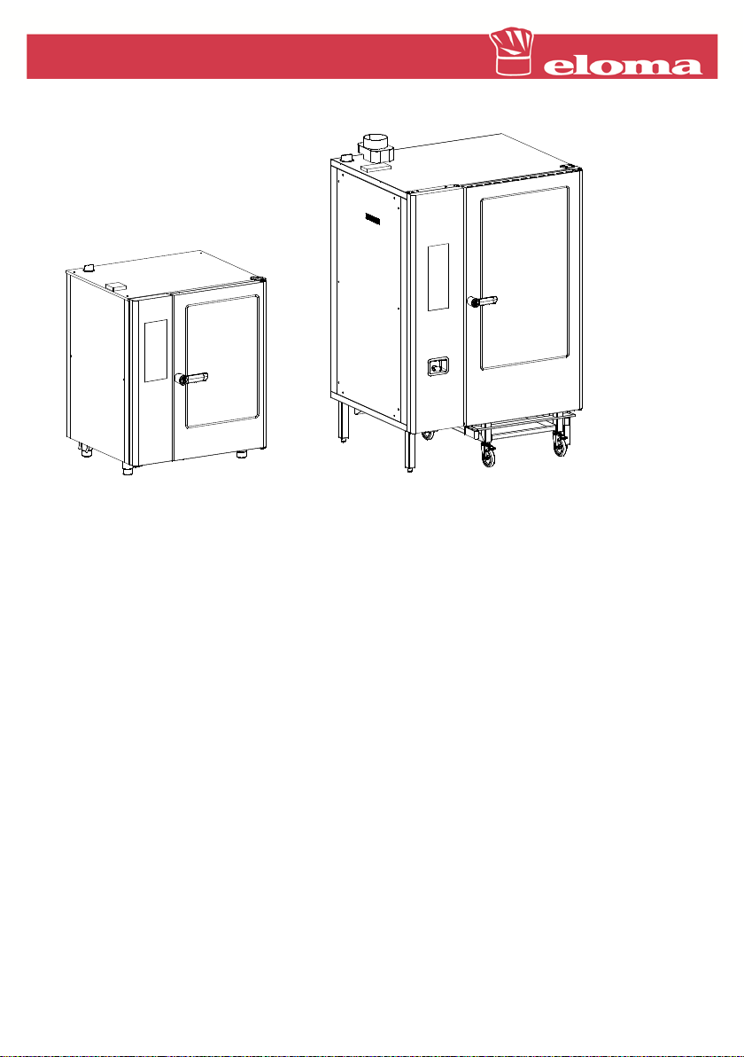
GeniusMT
Pos: 2 /953-Elo ma/Deckbla tt/Deckblatt _INS_Titelbil d_GeniusT _Multimax @ 9\ mod_13795950 14563_6.doc @ 88124 @ @ 1
=== Ende der Liste für Tex tmarke Inhal t ===
=== Ende der Liste für Tex tmarke Inhal t1 ===
Pos: 6 /953-Elo ma/Deckbla tt/Deckblatt _Größen_Ene rgieart @ 9\mod _13795962624 31_6.doc @ 8 8231 @ @ 1
Sizes: 6-11, 10-11, 20-11, 12-21, 20-21
Type of energy: Gas and elect ri c
=== Ende der Liste für Tex tmarke Inhal t2 ===
Pos: 8 /953-Elo ma/Deckbla tt/Deckblatt _Installatio nsanleitung @ 9\mod_1379 596324705_6.d oc @ 88252 @ @ 1
Installation instructions
Subject to technical changes.
Read carefully before use.
Keep for future use.
=== Ende der Liste für Tex tmarke Inhal t3 ===
Page 2

Pos: 10 /953 -Eloma/Standar dtexte Dok umentart unabh ängig/Impre ssum @ 10\m od_1384361530 020_6.doc @ 101234 @ 44 4 @ 1
Imprint
Eloma GmbH . Innovative cooking and baking technology
Otto-Hahn-Str. 10
82216 Maisach
Germany
Phone: +49 (0) 8141 395-0
Fax: +49 (0) 8141 395-130
Cooking forum and user tips
Website: www.eloma.com
User hotline: + 49 ( 0) 35023 63887
Service
Service hotli ne: +49 (0) 35023 63888
Appliance type: ……………
Appliance no.: …………….
Dealer: Installer:
Date: …………… Installed on: ……………
=== Ende der Liste für Tex tmarke Inhal t4 ===
Page 3

About this d oc um e nt
Pos: 12 /953 -Eloma/Standar dtexte Dok umentart unabh ängig/IHZ @ 1 0\mod_138 9601392776_6.d oc @ 113662 @ @ 1
Table of Contents
1 About this document .................................................................. 5
1.1 Content and target audienc e ...................................................................5
1.2 Handling this document ...........................................................................5
1.3 Symbols used and layout of warnings .....................................................5
1.4 Use of images .........................................................................................6
1.5 Warranty and discl aim er of liability ..........................................................6
1.6 Models ....................................................................................................7
2 Safety ........................................................................................... 8
2.1 Qualifications of installation staff .............................................................8
2.2 Safety information ...................................................................................8
2.3 What to do in the event of a gas leak (wit h gas appli ances) ................... 11
3 Planning the installation ........................................................... 12
3.1 Appliance ov erview ............................................................................... 12
3.2 Appliance data ...................................................................................... 14
3.3 Connection data .................................................................................... 15
3.4 Installation location requirements .......................................................... 19
3.5 Minimum distances for operation and maintenance work ....................... 20
3.6 Minimum distances to ot her appliances ................................................. 21
4 Transporting the appliance ...................................................... 22
4.1 Transporting t he appliance with a lifting truck ........................................ 22
4.2 Unpacking the appliance ....................................................................... 22
5 Positioning the appliance ......................................................... 23
6 Connecting the appliance ......................................................... 25
6.1 Water connection .................................................................................. 25
6.2 Waste water connecti on ........................................................................ 30
3
Page 4

About this d oc um e nt
6.3 Electrical connection ............................................................................. 31
6.4 Exhaust air system (f or gas appli anc es) ................................................ 34
6.5 Gas connection (for gas appliances) ..................................................... 36
7 Initial start-up ............................................................................ 38
8 Dimension drawings ................................................................. 40
8.1 Dimension drawing: Si z e 6-11 and 10-11, electric ................................. 40
8.2 Dimension drawing: Si z e 6-11 and 10-11, gas ....................................... 41
8.3 Dimension drawing: Si z e 12-21 and 20-21, electric ............................... 42
8.4 Dimension drawing: Si z e 12-21 and 20-21, gas ..................................... 43
8.5 Dimension drawing: Si z e 20-11, electric ................................................ 44
8.6 Dimension drawing: Si z e 20-11, gas ..................................................... 45
=== Ende der Liste für Tex tmarke Inhal t5 ===
4
Page 5
About this d oc um e nt
1 About this document
Pos: 15 /953 -Eloma/Standar dtexte Ins tallationsanl eitungen/INS _Zu_Dokument _Inhalt un d Zielgruppe @ 9\ mod_13748 47313394_6.doc @ 78263 @ 2 @ 1
1.1 Content and target audience
These installation instructions describe how to transport, posi tion and
install the appliance safely. The installati on instructions are directed t o
people who will tr ansport , position and install the applianc e.
Pos: 16 /953 -Eloma/Standar dtexte Ins tallationsanl eitungen/INS _Zu_Dokument _Umgang mit diesem Doku ment @ 9\mod_1 3748474990 42_6.doc @ 7 8324 @ 2 @ 1
1.2 Handling this document
Keep these installation instructions accessible for installation staff .
Keep these installation instructions throughout the appliance's entire
life cycle.
Pass these install ation instructions on to subsequent owner s.
These install ation instructions incl ude a wiri ng diagr am of t he
appliance. The wiring diagram is supplied with the appliance. The
wiring diagram can be f ound in the installation area of table t op units
and in the control panel of fl oor-m ounted appliances. Make sure that
the wiring diagram is kept in the installation area or in the control
panel.
Pos: 17 /953 -Eloma/Standar dtexte Dok umentart unabh ängig/Zu_Dok ument_Verw endete Symb ole @ 9\mod_ 1374846264619 _6.doc @ 782 03 @ 2 @ 1
1.3 Symbols used and layo ut of wa r nings
Symbol Explanation
Warning: a warning follows this symbol.
Multi-step instruction: multiple instructions must be followed
1.
2.
in the given order.
Single-step instruc tion: exactly one instruc tion must be
followed.
Li s t of several single-step instructions:
instructions can be followed in any order.
Tab. 1: Explanation of the symbols used
5
Page 6

About this d oc um e nt
Information
DANGER!
Type and source of the danger!
Consequence: non-com pliance will result in death.
Action to avoid the danger.
WARNING!
Type and source of the danger!
Consequence: non-com pliance will result in serious i njury.
Action to avoid the danger.
CAUTION!
Type and source of the danger!
Consequence: non-compliance will result in minor injury.
Action to avoid the danger.
NOTE!
Type and source of the danger!
Consequence: non-com pliance will result in material damage.
Action to avoid the danger.
Technical not e or tip on oper ation.
Pos: 18 /953 -Eloma/Standar dtexte Dok umentart unabh ängig/Zu_Dok ument_Vew endung von Ab bildungen @ 9\ mod_13812997 70030_6.do c @ 90091 @ 2 @ 1
1.4 Use of images
Images are provided as ex am ples onl y and m ay differ from the appliance
supplied.
Pos: 19 /953 -Eloma/Standar dtexte Dok umentart unabh ängig/Zu_Dok ument_Gewäh rleistung und Haftungsa uschluss @ 9\mod_1374846 116382_6.doc @ 78183 @ 2 @ 1
1.5 Warranty and disclaimer of liability
You will find information on liability for material defects and warranty
conditions in our gener al terms and conditions of business (T&C).
Pos: 20 /953 -Eloma/Standar dtexte Dok umentart unabh ängig/Zu_Dok ument_Ger ätegrößen @ 11 \mod_14024963 59703_6.d oc @ 145048 @ 2 @ 1
6
Page 7

About this d oc um e nt
1.6 Models
The models are labelled with the number and type of levels.
Example: 6-11 means 6 levels of type GN 1/1.
Pos: 21 /953 -Eloma/Standar dtexte Dok umentart unabh ängig/Siche rheit_[Titel ] @ 9\mod_137 4846566048 _6.doc @ 78223 @ 1 @ 1
7
Page 8

Safety
2 Safety
Pos: 22 /953 -Eloma/Standar dtexte Ins tallationsanl eitungen/Si cherheit/INS_ Zu_Dokument _Qualifikati on des Install ationsperso nals_Gasgerät @ 9\mod_1 374847896576_ 6.doc @ 7836 4 @ 2 @ 1
2.1 Qualifications of installation staff
This appliance must be installed by an Eloma service partner.
Make sure that this appliance is only installed and started up by
persons who have read these entire installation instr uc tions and the
entire operati ng instr uc tions carefully and have understood the safety
information.
Make sure that the appliance is only connected to the water supply
by approved and authori sed skilled staff.
Make sure that the appliance is connected to the power supply only
by a qualified el ectri ci an: Comply with locally applicable regulations,
VDE regulations and the r egulations of the power supply company.
In the USA and Canada: Comply with locally applicable regul ations
and valid local codes with the National Electrical Code ANSI / NFPA
70 or the Canadian El ec trical Code CSA C22.2.
Make sure that the appliance is only connected to the gas supply by
the following skil led staff:
– Skilled staff from the gas supply company
– A competent officer provided by the manuf actur er ( c ertified by
the DVGW, the German Techni c al and Scientific Association for
Gas and Water)
– Skilled staff from the contracted installation company registered
with the gas supply com pany
– Skilled staff from an agency authori sed by a liquid gas bulk
Pos: 23 /953 -Eloma/Standar dtexte Dok umentart unabh ängig/Siche rheit_Sicher heitshinweise _[Titel] @ 9\mod_137542 7652506_6.doc @ 81001 @ 2 @ 1
2.2 Safety informatio n
Pos: 24 /953 -Eloma/Standar dtexte Ins tallationsanl eitungen/Si cherheit/INS_Si cherheit_U nsachgemäß e_Installati on @ 9\mod_137 9432441187_6. doc @ 87799 @ 3 @ 1
2.2.1 Imp rop er in st allation
distributor
Risk of injury from improper installation
Only perform the installation in accordance with these installation
instructions.
Do not modify the appliance.
Do not open the housing.
Pos: 25 /953 -Eloma/Standar dtexte Ins tallationsanl eitungen/Si cherheit/INS_Si cherheit_ Transport @ 9\ mod_137699898 5576_6.doc @ 82411 @ 3 @ 1
8
Page 9

Safety
2.2.2 Transport Risk of injury and material d amage from improper transport
Do not stack the appli anc e on a pallet.
Secure the applianc e against falling down on a pallet.
Risk of tipping and uncontro ll ed mo vements of appliances on
castors due to uneven floors
Only transport t he appliance on an even floor (max. 10° inclinat ion).
Move the appliance c ar efully.
When the appliance is i n the resting position, secure its castors with
the immobilisation brake.
Pos: 26 /953 -Eloma/Standar dtexte Ins tallationsanl eitungen/Si cherheit/INS_Si cherheit_Au fstellung @ 9\mod_137943 2555112_6. doc @ 87841 @ 3 @ 1
2.2.3 Positioning Risk of injury and material d amage from improper positioning
The appliance must be positioned by at least two persons.
Only position floor models on level gr ound.
Only stack applianc es that are intended for stacking.
With appliances i ntended for stacking:
– Only stack two appliances
– Secure the appliance against falling down
Pos: 27 /953 -Eloma/Standar dtexte Inst allationsanl eitungen/Si cherheit/INS_Si cherheit_ Gas_Anschluss @ 9\mod_13769 99699268_6 .doc @ 82431 @ 3 @ 1
2.2.4 Gas connection and exhaust gas equipment Risk of explosion from imp rop er gas connection
Make sure that only suit ably qualified experts connect the appliance
to the gas supply.
Comply with the locally applicable regulations of the professional
association and gas supply c ompany.
Switch off the appliance before connecting to the gas supply .
Observe the data on the type plate.
Check that the gas system is tight.
Route lines (particularly for appliances on castors) such that they
cannot become damaged.
If there is a smell of gas, observ e the rules of what to do in the event
of a gas leak (see section 2.3).
9
Page 10

Safety
Risk of poisoning and suffocation from improper dissipation of
exhaust gas
Install the exhaust gas system in accordance with legal
specifications.
Perform an exhaust gas test.
Risk of fire from hot exhaust gas pipe
Make sure that connecti ng c ables cannot touch the gas exhaust pipe
or the flow safeguard.
Make sure that the gas exhaust pi pe does not touch the flow
safeguard.
Pos: 28 /953 -Eloma/Standar dtexte Ins tallationsanl eitungen/Si cherheit/INS_Si cherheit_El ektrischerAns chluss @ 10\ mod_13862337 89847_6.doc @ 107652 @ 3 @ 1
2.2.5 Elect rical connection Electric shock from live parts
Make sure that only suit ably qualified experts connect the appliance
to the electric al suppl y .
Observe the data on the appliance type plate.
Replace any damaged el ectr ic al c ables immediately. Do not connect
any appliances with dam aged electrical cables.
Route lines (particularly for appliances on castors) such that they
cannot become damaged.
Do not connect the applianc e if you suspect it is damaged inside.
Pos: 29 /953 -Eloma/Standar dtexte Ins tallationsanl eitungen/Si cherheit/INS_Si cherheit_W asseranschl uss @ 10\mod_13 862338710 06_6.doc @ 1 07676 @ 3 @ 1
2.2.6 Water con nection
10
Water damage from improp er in st all at io n of the water connection
Make sure that only suit ably qualified experts connect the appliance
to the water supply.
Observe the data on the appliance type plate.
Route lines (particularly for appliances on castors) such that they
cannot become damaged.
Do not connect the applianc e if you suspect it is damaged inside.
Install a non-retur n v alv e c onforming to DIN EN 13959, Type EA in
the on-site drinking water installation upstream of the appliance.
Pos: 30 /953 -Eloma/Standar dtexte Dok umentart unabh ängig/Siche rheit_Verhal tensregeln_ Gasaustritt @ 9 \mod_1375709 071611_6.d oc @ 81402 @ 2 @ 1
Page 11

Safety
2.3 What to do in the event of a gas leak (with gas appliances)
1. Shut off the gas supply on sit e.
2. Do not touch any electrical switches.
3. Ventilate the room well.
4. Avoid creati ng nak ed flames or sparks.
5. Leave the room.
6. Contact the gas supply com pany .
Pos: 31 /953 -Eloma/Standar dtexte Ins tallationsanl eitungen/Inst allation plan en/Installa tion_planen_ [Titel] @ 9\mo d_1376046 242910_6.doc @ 8 1832 @ 1 @ 1
11
Page 12
Planni ng the ins t allatio n
3 Planning the installation
Pos: 32 /953 -Eloma/Standar dtexte Ins tallationsanl eitungen/INS _Installatio n_planen_Ge räteübersich t_[Titel] @ 9\m od_137948379 5494_6.doc @ 87914 @ 2 @ 1
3.1 Appliance overview
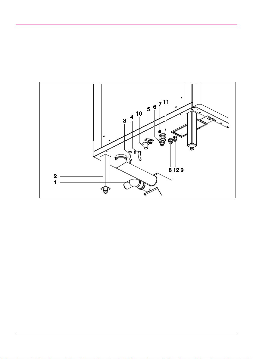
3.1.1 Connections on floor models
For appliances with door hinged on left: the connections are a mirror
image of those shown here.
Pos: 33 /953 -Eloma/INS_Ko mbidämpfer/G erätedaten /Gas-Gerät/INS_Ger äteü be rsicht (Gas ) @ 9\mod_1378 132140583 _6.doc @ 841 32 @ 3 @ 1
12
Fig. 1: Connections: size 12-21, 20-11 or 20-21, electric, gas
1 Connection for waste water line
2 Feet, adjustable
3 Connection for cleaning agent
4 Connection for rinse agent
5 Connection for soft water
6 Connection for har d water
7 Connection for potent ial equalisation
8 Connection for elec tric al c able (only for gas appliances)
Floating contact (optional) (only for elect ri c al appliances)
9 Air filter
10 Connection for gas li ne
11 Connection for elec tric al c able (only for electrical appliances)
12 Connection for ener gy optim iser (only for electrical appliances)
Pos: 34 /953 -Eloma/INS_Ko mbidämpfer/G erätedaten /INS_Geräteüb ersicht (El ektro) @ 9\ mod_13794836 46686_6.doc @ 87891 @ 3 @ 1
Page 13
Planni ng the ins t allatio n
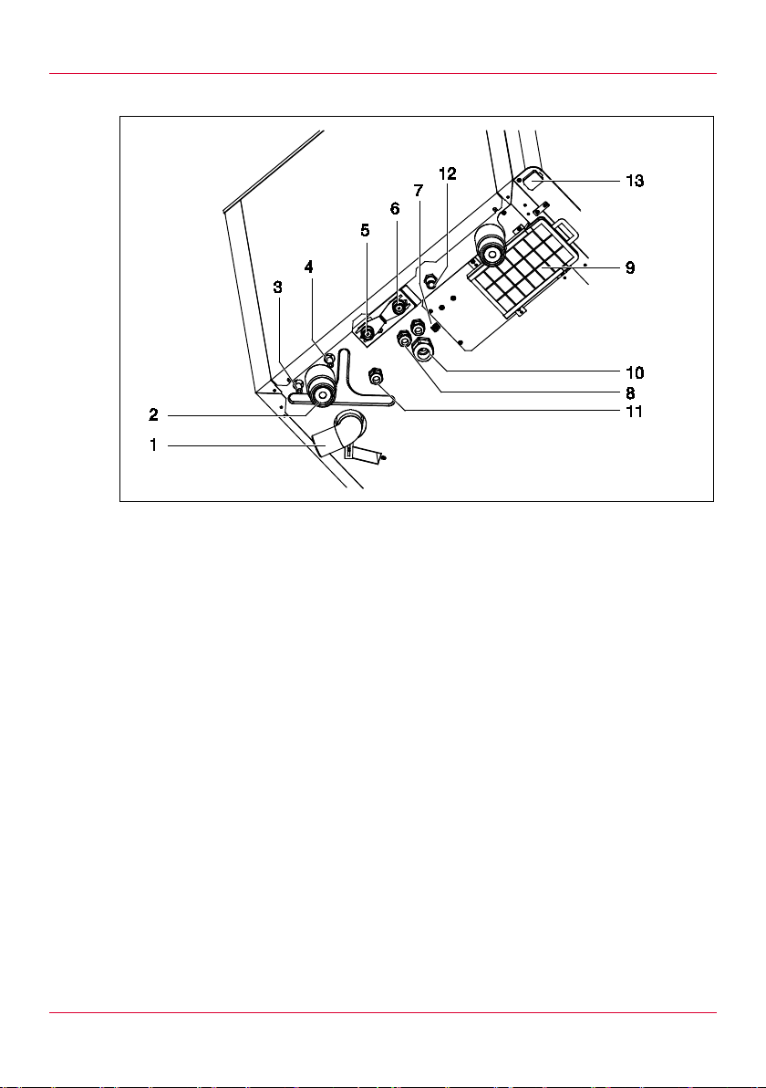
3.1.2 Connections on table top units
Fig. 2: Connections: size 6-11 or 10-11, electric, gas
1 Connection for waste water line
2 Feet, adjustabl e
3 Connection for cleaning agent
4 Connection for rinse agent
5 Connection for soft water
6 Connection for har d water
7 Connection for potent ial equalisation
8 Connection for elec tric al c able
9 Air filter
10 Connection for ener gy optim iser (only for electrical appliances)
11 Floating contact (optional) (only for elect ri c al appliances)
12 Connection for gas pi pe (onl y for gas appli anc es)
13 USB port
Pos: 35 /953 -Eloma/INS_Ko mbidämpfer/G erätedaten /INS_Daten_ Gerätedaten @ 9\ mod_13781 19463514_6.do c @ 84003 @ 2 @ 1
13
Page 14
Planni ng the ins t allatio n
Values in brackets apply to 1/1 appliances.
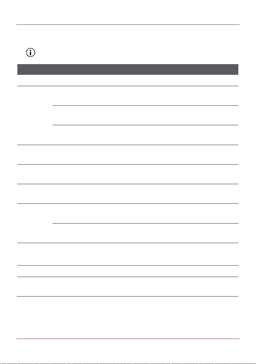
Grid spacing
3.2 Applianc e da ta
Applianc e da ta 6-11 10-11 20-11 12-21 20-21
Housing Stainless steel
Appliance
Width
dimensions
[mm (inch)]
Depth
Height
Number of levels
[mm (inch)]
Temperature in the
chamber [°C (°F)]
Weight [kg
Electric
(lb)]
Gas
Packaging weight
[kg (lb)]
925
(36 3/8)
805
(31 5/8)
840
(33 1/8)
7 x
GN1/1
925
(36 3/8)
805
(31 5/8)
1120
(44 1/8)
11 x
GN1/1
67 (2.6)
30 – 300 (86 – 572)
130
(286.6)
140
(308.6)
31
(68.3)
167
(368.2)
177
(390.2)
35
(77.2)
1030
(40 1/2)
875
(34 1/2)
1941
(76 3/8)
20 x
GN1/1
295
(650.4)
320
(705.5)
133
(293.2)
1312
(51 5/8)
1088
(42 7/8)
1495
(58 7/8)
12 (24) x
GN2/1 (1/1)
350
(771.6)
365
(804.7)
101
(222.7)
1312
(51 5/8)
1088
(42 7/8)
1928
(75 7/8)
20 (40) x
GN2/1 (1/1)
495
(1091.3)
530
(1168.4)
107
(235.9)
Noise level [db (A)] <70
Permissible am bient
+4 (+39)
temperature [°C ( °F) ]
Tab. 2: Appliance data
Pos: 36 /953 -Eloma/Standar dtexte Ins tallationsanl eitungen/Inst allation plan en/Installa tion_planen_A nschlussdate n @ 9\mod_1376046 419939_6.d oc @ 81872 @ 2 @ 1
14
Page 15
Planni ng the ins t allatio n
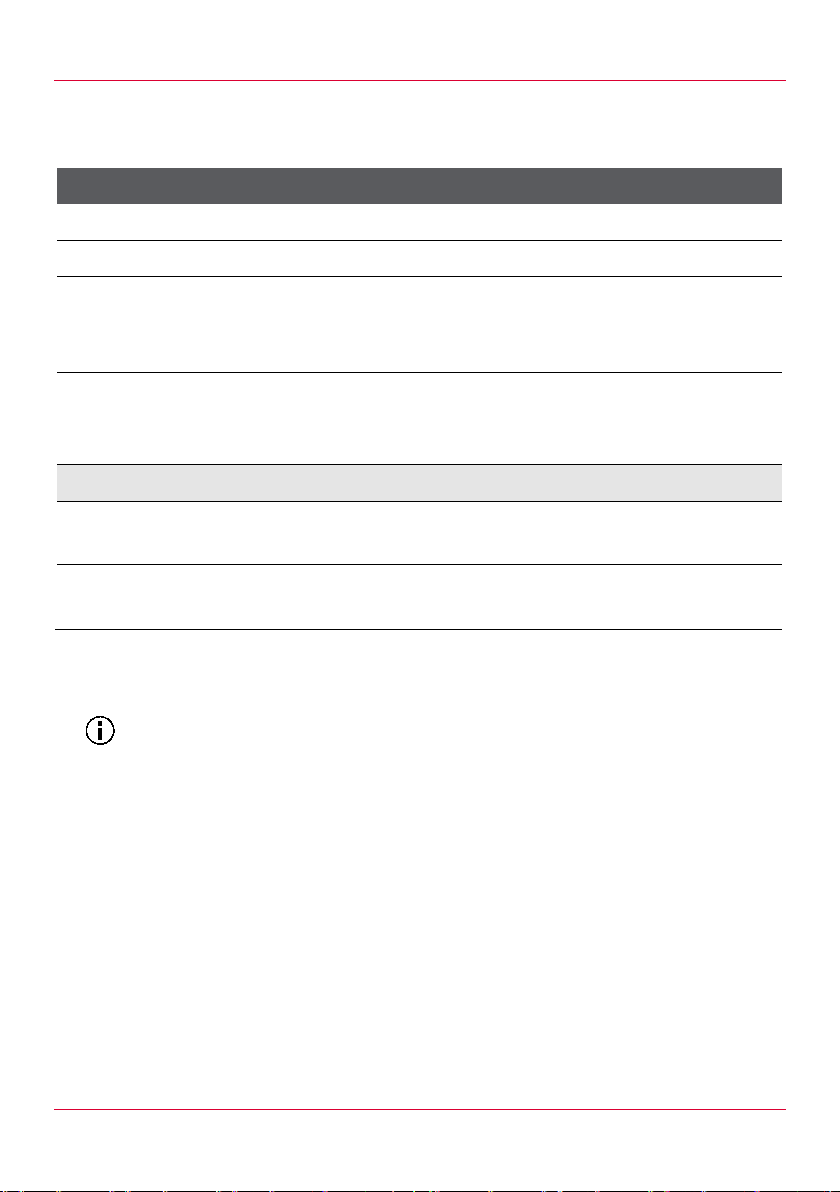
Connection
The specified values for hard water are dependent on pressure and
3.3 Connec tion data
Pos: 37 /953 -Eloma/INS_Ko mbidämpfer/G erätedaten /INS_Wassera nschluss @ 9 \mod_13781317 76686_6.do c @ 84071 @ 3 @ 1
3.3.1 Water con nection
Water connection 6-11 10-11 20-11 12-21 20-21
Water type Drinking water
Water connecti on 2 x G ¾ A
Connection ty pe ½“ hose with ¾“ screw union and fl at packi ng
(flexible, pr essure-re si stant, tested by the DVGW and
approved in accordanc e with EN 61770)
2 – 6/200 – 600 (29.0 – 87.0)
pressure [bar]/
[kP (PSI)]
Flow rate (dependent on pr essure)
Soft water
[l/h (oz/h)]
Hard water
[l/h (oz/h)]
Tab. 3: Water connection
correspond to a pressure of 4 bar / 400 kPa.
Pos: 38 /953 -Eloma/INS_Ko mbidämpfer/G erätedaten /INS_Abwass er @ 9\mod_137813 1871980_6. doc @ 84091 @ 3 @ 1
16
(541.0)
55
(1859.8)
19
(642.5)
55
(1859.8)
20
(676.3)
65
(2197.9)
25
(845.4)
55
(1859.8)
25
(845.4)
65
(2197.9)
15
Page 16
Planni ng the ins t allatio n
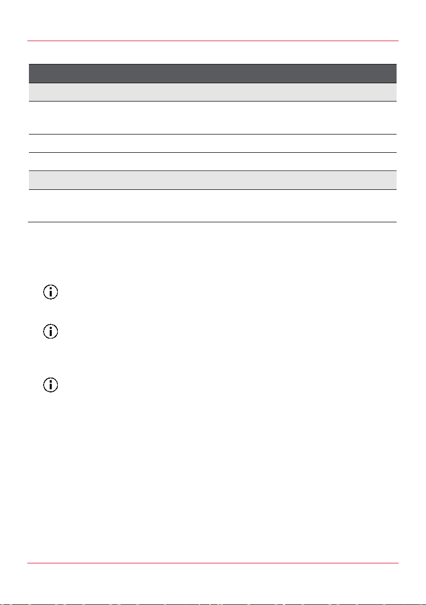
Waste water connection
Value
Values in brackets apply for reduced heating power.
Applicable for all electrical connections: Use residual current operated
In view of the components i n the devic e ( transformers, capacitors, etc.),
3.3.2 Waster water connection
Waste water line
Minimum diamete r
50 (1.97)
[mm (inch)]
Maximum length [m (yd)] 1 (1.1)
Material HT pipe PA-I 1818 DIN 16560
Waste water
Maximum temperature
80 (176)
[°C (°F)]
Tab. 4: Waste water connection
Pos: 39 /953 -Eloma/INS_Ko mbidämpfer/G erätedaten /INS_Elektroan schluss_Gas @ 9\mod_13 78190428291_6 .doc @ 84323 @ 3 @ 1
3.3.3 Elect rical connection
circuit breaker.
we recommend a miniature circuit-breaker with cut-out characteristic D
for connecting t he appliance.
16
Page 17
Planni ng the ins t allatio n
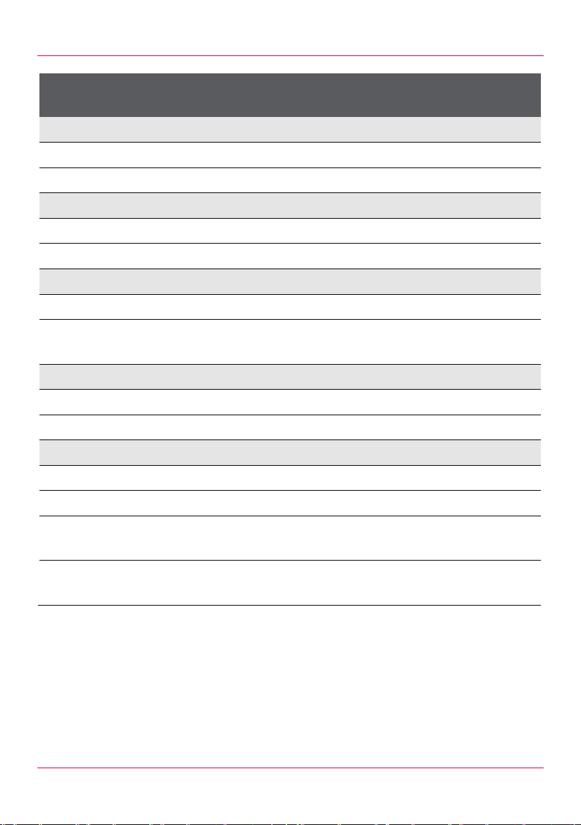
Electrical connection for
6-11 10-11 20-11 12-21 20-21
electrical appli ances
3 AC 200 V
Connected load [kW] 9 17 35 20 40
Electrical protection [A] 3x32 3x63 3x125 3x63 3x125
3 AC 230 V
Connected load [kW] 12 22 45 26 52
Electrical protection [A] 3x32 3x63 3x125 3x80 3x160
3 AC 400 V/3 NAC 400 V
Connected load [kW] 12 17 45 (35) 34 (26) 68 (52)
Electrical protection [A] 3x20 3x32
3x80
(3x63)
3x63
(3x50)
3x100
(3x75)
3 AC 208 V
Connected load [kW] 9.25 18.32 36.55 21.52 42.75
Electrical protection [A] 3x32 3x63 3x125 3x63 3x125
3 AC 480 V
Connected load [kW] 9.5 18.5 36.5 21.5 43
Electrical protection [A] 3x16 3x32 3x50 3x32 3x63
Dissipation of heat, latent 3.960 6.120
Dissipation of heat,
2.772 4.284
sensitive
Tab. 5: Electrical connection for electrical appliances
16.200
(12.240)
11.340
(8.568)
12.240
(9.360)
8.568
(6.552)
24.480
(18.720)
17.136
(13.104)
17
Page 18
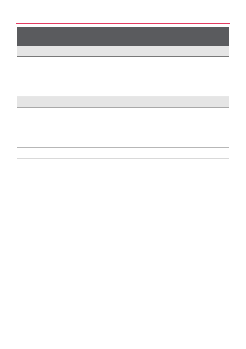
Planni ng the ins t allatio n
Electrical con ne c t io n f or
6-11 10-11 20-11 12-21 20-21
gas appliances
1 NAC 230 V
Connected load [kW] 12 20 40 35 70
Connected load, elec trical
1.0 1.0 1.92 1.44 2.4
[kW]
Electrical protection [A] 1x16 1x16 1x16 1x16 1x16
1 NAC 110 V
Connected load [kW] 12 20 40 35 70
Connected load, elec trical
1.0 1.0 1.92 1.44 2.4
[kW]
Electrical protection [A] 1x16 1x16 1x20 1x16 1x25
Dissipation of heat, latent 4.320 7.200 14.200 12.600 25.200
Dissipation of heat, sensit ive 3.672 6.120 12.240 10.710 21.420
Prescribed minimum
3x1.5
connection cr oss-section
2
[mm
]
18
Tab. 6: Electrical connection for gas appliances
Pos: 40 /953 -Eloma/INS_Ko mbidämpfer/G erätedaten /INS_Gasansc hluss @ 9\mod_ 137813353 4788_6.doc @ 84 111 @ 3 @ 1
Page 19
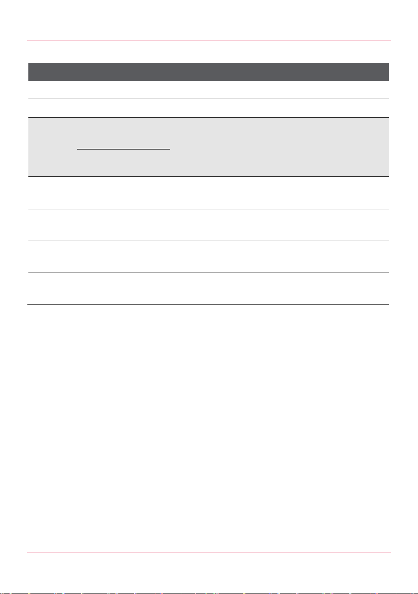
Planni ng the installation
3.3.4 Gas connection for gas appliances
Gas connection 6-11 10-11 20-11 12-21 20-21
Connected load [kW] 12 20 40 35 70
Gas connection [i n] 1/2 1/2 3/4 3/4 3/4
Gas type
Connection
pressure
[mbar] [kPa]
Heating
value
3
[MJ/m
(Btu/ft³)]
Natural
18 – 25 1.8 – 2.5
gas E(H)
Natural
20 – 30 2.0 – 3.0
gas L
Propane 25 – 57 2.5 – 5.7
34
(912.5)
29
(778.3)
88
(2361.8)
Butane 25 – 57 2.5 – 5.7
116
(3113.3)
Tab. 7: Gas connection for gas appliances
Pos: 41 /953 -Eloma/INS_Ko mbidämpfer/G erätedaten /Gas-Gerät/INS_ Installation _planen_A nforderung an den Aufstello rt (Elektr o und Gas) @ 9\m od_1374849 640893_6.doc @ 78391 @ 2 @ 1
3.4 Installation locat ion requirements
Ambient temperatures: >4 °C (>39 °F)
Free of toxic or explosive gases or substances
If the appliance is to be operated outdoors: protect ed from rain,
thunderstorms, lightning strikes and wind
If a gas appliance is being used with liquid gas: above ground lev el
We recommend positi oning the appliance underneath an extrac tion
hood.
Pos: 42 /953 -Eloma/INS_Ko mbi dä mpf er/I nst alla t ion plan en/ INS _I nstal la ti on_ plan en_R aumbedarf @ 9\mod _137604648129 3_6.doc @ 81 892 @ 2 @ 1
Maximum gas consumption at rated
thermal load [m3/h])/[kg/h]
1.3 2.1 4.2 3.5 7.0
1.4 2.5 4.9 4.1 8.2
0.47/
0.85
0.37/
0.86
0.82/
1.6
0.62/
1.6
1.6/
3.2
1.2/
3.3
1.4/
2.7
1.0/
2.7
2.7/
5.3
2.0/
5.4
19
Page 20
Planni ng the ins t allatio n
Clearance for mobile tray rack
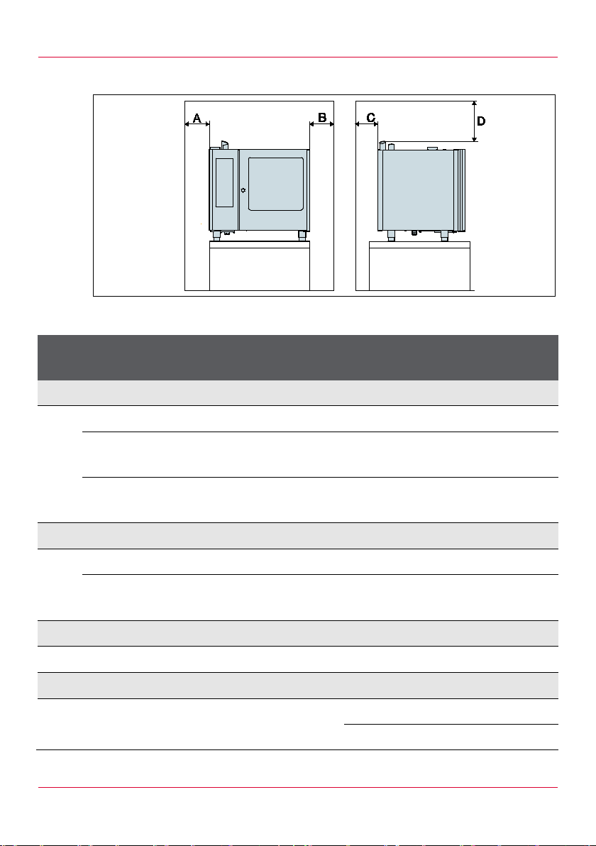
3.5 Minimum distances for operat ion and maintenance work
Fig. 3: Minimum distances for table top units and floor models
Item Spacing [mm (inch)]
Table top
Floor model
unit
A Side with Control Panel to wall
Minimum distance >50 (1.97) >50 (1.97)
Clearance for maintenance work
– >500 (19.7)
(recommended)
– 800 (31.5)
(recommended)
B Side opposite Cont r ol P anel to wall
Minimum distance >50 (1.97) >50 (1.97)
Clearance for mobile tray rack
– 800 (31.5)
(recommended)
C Rear of appliance to wall
Minimum distance >50 (1.97) >50 (1.97)
D Top edge of appliance to ceiling
Extraction hood pr ov ided on site >50 (1.97) >50 (1.97)
No extraction hood prov ided on site >1000 (39.4) >1000 (39.4)
Tab. 8: Minimum distances for table top units and floor models
20
Page 21
Planni ng the ins t allatio n
Item
Spacing [mm (inch)]
Table top unit
Floor model
Pos: 43 /953 -Eloma/INS_Ko mbidämpfer/I nstallation planen/INS_I nstallation_ planen_Mind estabstände @ 9\mod_137948 4467132_6. doc @ 87935 @ 2 @ 1
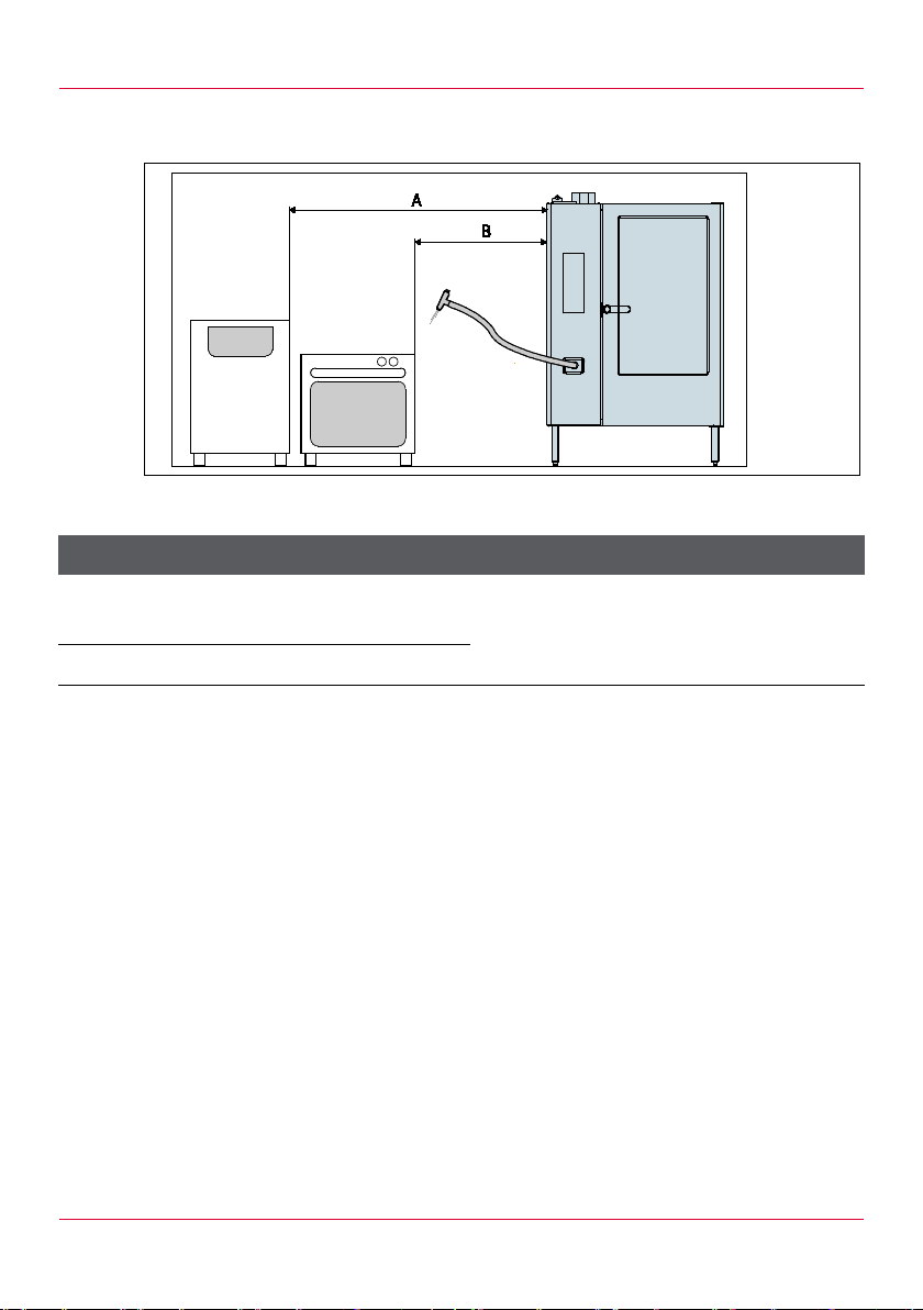
3.6 Minimum distances to oth er appliances
Fig. 4: Minimum distances to other appliances
A
Appliance to sources of heat or
moisture (e.g. baking oven)
B Appliance to deep fat fryer
Tab. 9: Minimum distances to other appliances
Pos: 44 /953 -Eloma/Standar dtexte Ins tallationsanl eitungen/Ger ät_transpo rtieren/INS_Ger ät_transpor tieren_[Titel] @ 9\mod_13 76046581735_ 6.doc @ 8191 2 @ 12 @ 1
>500 (19.7)
> radius of action of
the hand shower
21
Page 22

Transporting the appliance
4 Tra nsporting the appliance
4.1 Transporting the appliance with a lifting truck
Use a lifting truc k to transport , lift and lower the appliance.
Only transport t he appliance on a pallet.
Observe the requir ed cl ear anc e height and width.
Pos: 45 /953 -Eloma/Standar dtexte Inst allationsanl eitungen/Ger ät_transporti eren/INS_Ger ät_auspacken @ 9\mod_13 76049012641_6 .doc @ 81982 @ 2 @ 1
4.2 Unpacking the appliance
1. Take all boxes, pack aging m aterial, accessories and documents out
of the chamber.
2. Dispose of packagi ng in ac c or danc e with local regulations.
3. Remove the protective film from the sides, rear and top.
4. Remove residue wit h a glass cleaner .
5. Check the appliance for damage. If the appliance is damaged:
– Do not install the appliance.
– Contac t your Eloma service partner .
Pos: 46 /953 -Eloma/Standar dtexte Ins tallationsanl eitungen/Ger ät_aufstellen/ INS_Gerät_ aufstellen_ (Tisch/Standge räte) @ 9\m od_137604884 5027_6.doc @ 81942 @ 1 @ 1
22
Page 23
Positioning the appliance
Gas appliances must not be used as mobile devices.
5 Positioning the appliance
WARNING!
Injury from uncontrol led movements of the appliance!
Crushing under the appliance feet
The appliance must be lif ted from the pallet by at least two persons.
Pay attention to fi nger s when setting the appliance down.
Do not install gas appli anc es on moving surfaces (e.g. on castors)
1. Observe local and general rules relating to kitchen equipment.
2. If the appliance is installed in the vicinity of materials that are
sensitive to heat or at ri sk of cat c hing fire, observe the relevant fire
protection regulations.
3. Ensure that the instal lation location requirem ents are met (see
section 3.4).
4. Ensure that the minimum distanc es are complied with (see
section 3.5, see section 3.6).
5. Secure the applianc e against tilting, falli ng down and becoming
displaced.
6. Remove the transportation locking device from the chamber.
7. Remove the protective cap from the core probe.
8. Check the appliance for external damage. Do not connect the
appliance if you suspect i t is damaged inside.
9. Make sure that the air baffle is locked in place.
10. Make sure that the fat filter and drain filter are secure.
11. Make sure there ar e no c om bustible materials above the appl iance.
12. Make sure that the supply air opening and the ventilation slots are
unobstructed and not c ov er ed.
13. Keep the area between the appliance feet unobstruc ted to ensure
sufficient v entilation below the appliance.
14. For t able top units: make sure that the install ation position can bear
the weight of the applianc e ( see section 3.2).
23
Page 24
Positioning the appliance
We recommend placing t able top units on support stands, cabinets or
1
2
thermal cabinets.
15. For appliances on castors: secure the castors with the foot brake.
16. For appliances with appliance feet: posi tion the appliance so it is
level. If necessary, use the height-adjustable appliance feet to
compensate for any minor unevenness.
17. For floor models:
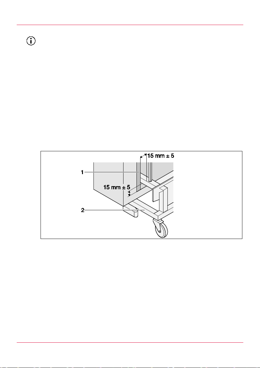
– Adj ust the appliance so a distance of 15 ±5 mm (0.59 ±0.2 in) is
maintained between the mobile tray rack and the top edge of the
chamber floor.
– Adjust the appliance so the mobile t r ay rack (2) is not in contac t
with the door seal (1).
Fig. 5: For floor models: distance between door seal and mobile tray rack
Door seal
Mobile tray rack
Pos: 47 /953 -Eloma/Standar dtexte Ins tallationsanl eitungen/Ger ät_anschließe n/INS_Gerä t anschließen _[Titel] @ 9\mod_1376049 119270_6.doc @ 82003 @ 1 @ 1
24
Page 25

Connecting the appliance
6 Connecting t he appliance
Pos: 48 /953 -Eloma/Standar dtexte Ins tallationsanl eitungen/Ger ät_anschließe n/INS_Wass eranschluss_[ Titel] @ 9\mod _13781405 36982_6.doc @ 84234 @ 2 @ 1
6.1 Water connection
Pos: 49 /953 -Eloma/INS_Ko mbidämpfer/G erät anschli eßen/Wasse ranschluss/INS _Wasseransc hluss_Grenz werte @ 9\mod_ 137604915 6544_6.doc @ 82023 @ 3 @ 1
6.1.1 Li mit values
Parameter Limit value
Total hardness ≤3° dH
pH value 7.0 – 8.5
Conductivity ≤90 µS/cm
Cl- <60 mg/l
SO4 <100 mg/l
SiO4 <10 mg/l
Fe <0.05 mg/l
Mn <0.05 mg/l
Cu <0.05 mg/l
CI2 <0.1 mg/l
Tab. 10: Water limit values
Pos: 50 /953 -Eloma/INS_Ko mbidämpfer/G erät anschli eßen/Wasse ranschluss/INS _Wasseransc hluss_Varia nten @ 9\mod _13781366469 17_6.doc @ 8 4152 @ 3444 @ 1
25
Page 26
Connecting the appliance
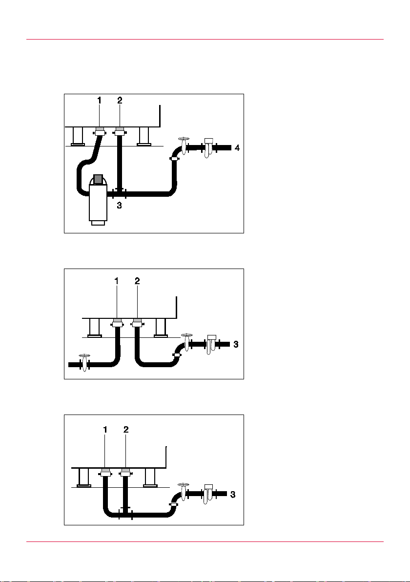
6.1.2 Water con nection versions Water connection for raw water f rom the mains supply, with a water
softeni n g unit
Water connection for so f t wat er and raw water
1 Soft water connecti on
2 Hard water connection
3 Water softening unit
4 Water connecti on
1 Soft water connecti on
2 Hard water connection
3 Water connecti on
26
Water connection for o smosi s f rom the mains supply
1 Soft water connecti on
2 Hard water connection
3 Water connecti on
Pos: 51 /953 -Eloma/INS_Ko mbidämpfer/G erät anschli eßen/Wasse ranschluss/INS _Wasseransc hluss_install ieren @ 9\mo d_13781402 98109_6.doc @ 84194 @ 3 @ 1
Page 27

Connecting the appliance
The soft water connection and hard water connection are labell ed on
6.1.3 Installing the soft water connection and hard water connection
NOTE!
Material damage f rom improper water connection!
Water damage
Make sure that the appliance is only connected to the water supply
by approved and authori sed skilled staff.
Observe the connection labels on the appliance.
NOTE!
Material damage from installing the wrong wat er treatmen t syst ems!
Damage to glass pane, cham ber and par ts of the appliance
Do not install a sodium ion exc hanger .
Do not install any system s that use silicate dosing.
Do not install any system s based on electromagnetic fields.
the applianc e.
Check the water qualit y and water har dnes s with y our loc al water
supply company.
Observe the connection labels on the appliance.
If the water contai ns impurities such as sand, iron particles or
suspended partic les: install a 5 – 15 µm fine filter (e.g. activated
carbon filt er ) for the soft and hard water connections.
27
Page 28
Connecting the appliance
Install a hydrogen ion exchanger for
Install an activated carbon filter for
-
Install a reverse osmosi s system for
Reverse osmosis systems are an alternative to full and parti al
If limit values are exc eeded, perform the following acti ons:
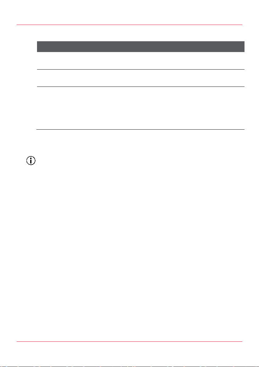
Limit value exceeded Action
Total hardness >3 °dH
the soft water connection.
Cl
>0.1 mg/l
2
the soft and hard water connect ions.
Cl
>60 mg/l and
≥ 10 mg/l
SiO
4
the soft and hard water connections.
Make sure that a residual hardnes s
with a conductivit y of 10 µS/cm is
maintained.
Tab. 11: Actions to take if limit values are exceeded
demineralisation via filter systems. A reverse osmosi s system removes
water-hardening substanc es and no n-har dening minerals from water.
Pos: 52 /953 -Eloma/Standar dtexte Betri ebsanleitu ngen/Gerät_rei nigen/Gerät_ reinigen_V orgeschriebe ne Reiniger @ 1 0\mod_138 4174860658_6. doc @ 100545 @ 3 @ 1
6.1.4 Prescribed cleaning and rinse agents
The following cleaning and rinse agents are approv ed for cl eaning the
chamber:
Eloma multi-clean special cleaner
Eloma multi-clean rinse aid
Pos: 53 /953 -Eloma/Standar dtexte Inst allationsanl eitungen/Ger ät_anschließe n/INS_autocl ean_Anschlus s_installi eren_[Titel] @ 9\mod_13760 49228490_6 .doc @ 82063 @ 3 @ 1
28
Page 29

Connecting the appliance
The connecti ons f or the cl eaning and rinse agents are labelled on the
6.1.5 Installing the autoclean connection
WARNING!
Risk of chemical burns f rom cl eaning ag ents!
Chemical burns to the skin and eyes
Wear protective clothing (e.g. long-sleeved clothing, protective glov es
and glasses).
Observe the safet y information for the prescribed cl eaning and ri nse
agents (see section 6.1.4).
NOTE!
Material damage from mixing up cleaning and rinse agents!
Observe the connection labels on the appliance.
Attach the cleani ng agent to the red canister connection.
Attach the rinse agent to the blue canister connection.
NOTE!
Material damage from incorrect cleaning or rinse agent!
Only use the prescribed cleaning and rinse agents (see
section 6.1.4).
appliance.
1. Determine the installation location of the canisters:
– For floor models: position the canister s on the floor:
– For table top units: position the canisters below the bottom edge
of the appliance.
– Maximum delivery head: 1.5 m (1.64 yd)
– Maximum delivery distance: 10 m (10. 9 yd)
2. Observe the connection labels on the appliance:
– At tach the cleaning agent to the red cani ster c onnec tion.
– At tach the rinse agent to the blue canister connec tion.
Pos: 54 /953-Elom a/Standardtex te Installati onsanleitun gen/Gerät_ anschließen/IN S_Abwasser anschluss_[ Titel] @ 9\mo d_13781406669 43_6.doc @ 8 4254 @ 2 @ 1
29
Page 30
Connecting the appliance
6.2 Waste water connection
Pos: 55 /953 -Eloma/INS_Ko mbidämpfer/G erät anschli eßen/Abwasse ranschluss/ INS_Abwass eranschluss_V arianten @ 9\mod_1376049 193519_6.d oc @ 82043 @ 3444 @ 1
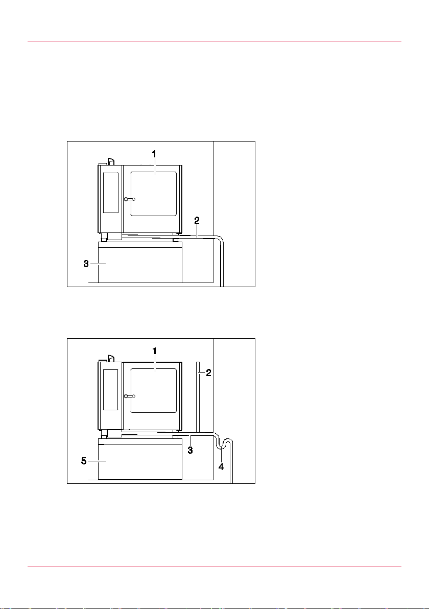
6.2.1 Waste water connection versions Fixed connection
Application: any , as the appliance is intrinsically safe as per the
regulati ons of the DVGW .
Fixed connection with air exhaust pipe
Application: when an ex ternal siphon is present.
1 Appliance
2 Fixed connection
3 Cabinet
1 Appliance
2 Air exhaust pipe
3 Fixed connection
4 Siphon
5 Cabinet
30
Page 31
Connecting the appliance
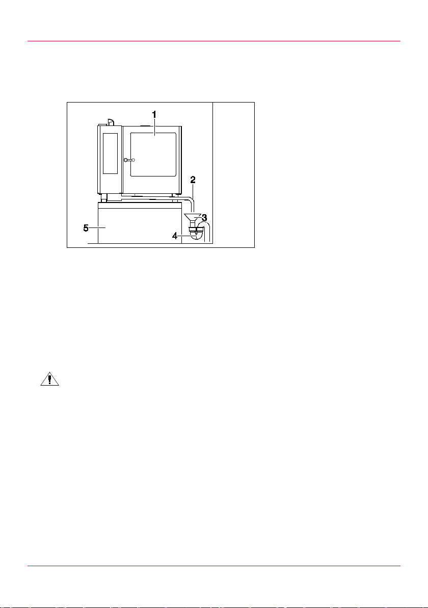
Waste water drain into ven t tundi sh
Application: when an ex ternal siphon is present or the diameter of t he
external waste water pipe is too small.
1 Appliance
2 Waste water pipe
3 Vent tundish
4 Siphon
5 Cabinet
Pos: 56 /953 -Eloma/INS_Ko mbidämpfer/G erät anschli eßen/Abwasse ranschluss/ INS_Abwass er_installie ren @ 9\mod_13 78140777810_6 .doc @ 84274 @ 3 @ 1
6.2.2 In st all in g the waste water connection
1. Observe the local waste water regul ations.
2. Determine the connection version (see section 6.2.1).
3. Install the waste water pipe such that the slope is at least 5%.
4. Add three litres of water (101.4 oz) to the chamber to fill the siphon.
Pos: 57 /953 -Eloma/INS_Ko mbidämpfer/G erät anschli eßen/Elektro anschluss/INS _Elektroans chluss_ins tallieren @ 9\ mod_137819024 9628_6.doc @ 84302 @ 23 3 @ 1
6.3 Electrical connect ion
DANGER!
Electric shock from improper installation!
Make sure that the appliance is connected to the power supply only
by a qualified el ectri ci an:
Comply with locally applicable regulations, V DE regulations and the
regulati ons of the power suppl y c om pany .
Incorporate t he appliance into the equipotential bonding system.
31
Page 32
Connecting the appliance
The appliance must be connec ted via a fixed connection.
DANGER!
Electric shock from damaged cables!
Replace any damaged el ectr ic al c ables immediately. Do not connect
any appliances with dam aged electrical cables.
Route cables such that t hey ar e protec ted against becoming
damaged during operation.
6.3.1 Installing the electrical connection
Observe the data on the type plate.
Establish the fixed connection:
– Connect the power cable to the terminals securely .
– Make sure t hat the phases are connected correct ly.
Customer to provi de and install an all-pole electric disconnecting
device upstream of the appliance. This device must comply with t he
applicable regulations and standards and provide complete
disconnection under c ategory III overvoltage.
If a connecting cabl e is not incl uded in the scope of supply, use a
cable which meets the r elev ant applicable regulations and standard s
and the following specifications:
– Mains connecting cables must be oil-resistant, sheathed, flexible
cables. They must not be lighter than a standard polychloroprene
or other equivalent synthetic elastomer-sheathed cabl e that is
identified as compliant with 60245 IEC 57.
32
Page 33
Connecting the appliance
a
a
a
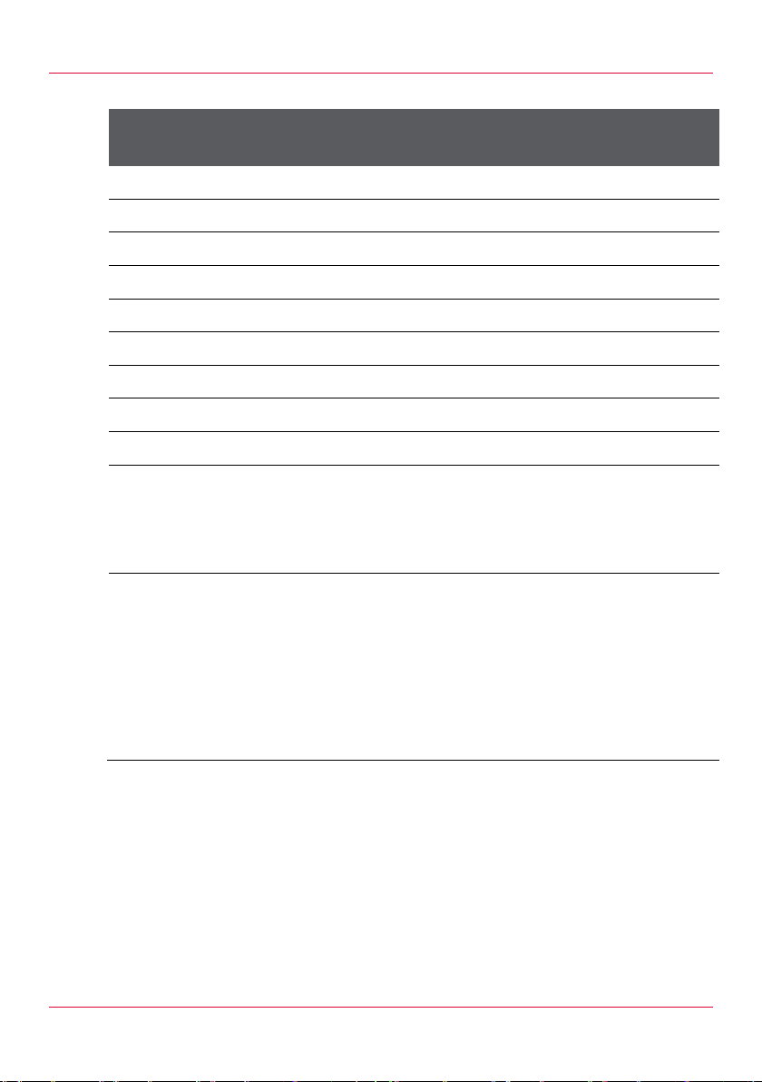
– The following cable cross-sections must be observed:
Rated current of the
Nominal cross-section [mm²]
appliance [A]
≤ 0.2 Tinsel conductor cable
> 0.2 and ≤ 3 0.5
> 3 and ≤ 6 0.75
> 6 and ≤ 10 1.0 (0.75)b
> 10 and ≤ 16 1.5 (1.0)b
> 16 and ≤ 25 2.5
> 25 and ≤ 32 4
> 32 and ≤ 40 6
> 40 and ≤ 63 10
NOTE: For mains connecting cables of polyphase appliances, t he
nominal conductor c r oss-section is based on the largest conduct or crosssection for each phase at the point where the mains connecting c able is
connected to the appliance terminals.
These cables may only be used provided that the length of the
cable between the point at which the cable or bend protection
grommet enters the appliance and the entry to the plug is no
more than 2 m.
b
Cables with the cross-sectional values specified in br acket s may
be used for portable appli anc es provided that they are no more
than 2 m long.
Tab. 12: Minimum conductor cross-section
Install a residual-current-operated circuit -br eak er on si te in
accordance with the r elevant applicable regul ations. We recommend
a type B residual-current-operated circuit-breaker with a tripping
current of 30 mA.
For appliances with t he ener gy optimiser system: connect the
appliance t o an energy optimiser system (not included in the scope of
supply).
33
Page 34
Connecting the appliance
6.3.2 Connectin g po t e ntial equalisation
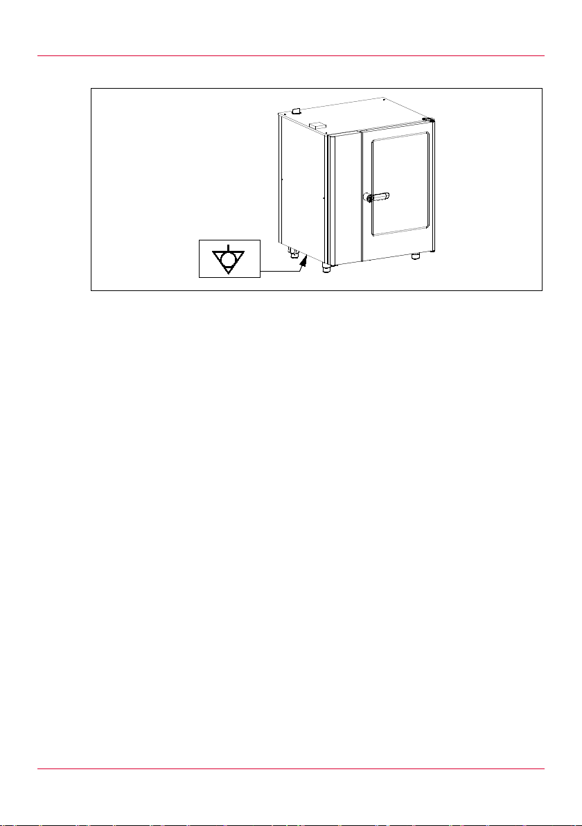
Fig. 6: Connection label for equipotential bonding
Connect the equipotential bonding cable to the appliance(see
section 3.1.1).
Pos: 58 /953 -Eloma/INS_Ko mbidämpfer/G erät anschli eßen/Abgas anlage/INS_Ab gasanlage @ 9 \mod_1378 195708021_6.d oc @ 84345 @ 234 @ 1
6.4 Exhaust air system (for gas appliances)
Agree the design of the exhaust gas system with the responsible
district chim ney sweep.
Place the design of t he exhaust gas system on record.
If exhaust air and exhaust gas are bei ng discharged from type B gas
appliances toget her , observe the relevant national/state building
regulations.
Type B gas appliance: gas appl iance with exhaust gas system
, B23 with fan upstream of the burner)
(B
13
34
Page 35
Connecting the appliance
Type B
gas appliances do not require fl ow protec tion.
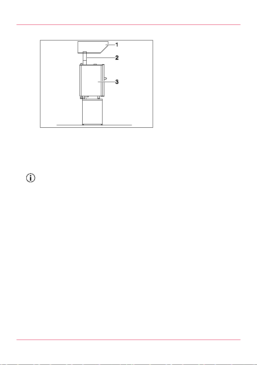
6.4.1 Positioning the appliance under a vapour extraction hood (B23)
1 Vapour extracti on
hood
2 Exhaust gas pipe
3 Appliance
Make sure that the vapour extr ac tion hood meets the relevant
specifications (DVGW work sheet G 634).
Make sure that the vapour extr ac tion hood is suitable for exhaust gas
temperatures of 500 ° C ( 932 °F).
23
Install a flame protection filter.
Maintain a distance equivalent to 1.25 to 2 times the diamet er of the
exhaust gas pipe between the exhaust gas pipe and the flam e
protection filter.
Install a safety dev ic e whic h ensures that gas can only be supplied to
the burner when the vapour ex traction hood is switched on.
35
Page 36
Connecting the appliance
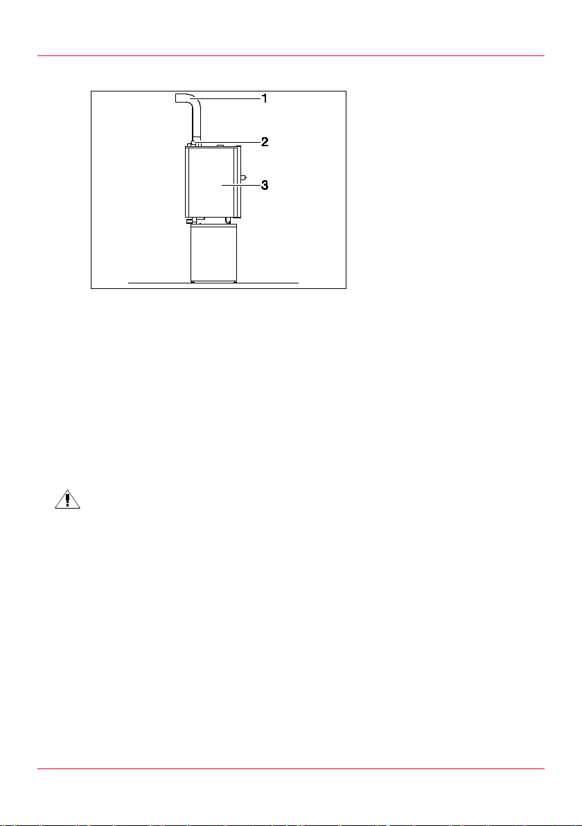
Connecting the appli ance to the exhaust gas system (B13)
Make sure that the house chimney meets the relevant specific ations
(DIN 18160, Part 1).
Make sure that the exhaust gas system m eets the relevant
specifications (DVGW work sheet G 660).
Install flow protection.
Make sure that the pipes which come into contact with exhaust gases
are resistant to heat .
Pos: 59 /953 -Eloma/INS_Ko mbidämpfer/G erät anschli eßen/Gasans chluss/INS_G asanschluss @ 9\mod_13760 49493280_6 .doc @ 82123 @ 2 @ 1
6.5 Gas connection (for g as appliances)
DANGER!
Risk of explosion from in correct gas connection!
Serious burns on the skin
Make sure that the appliance is only connected to the gas supply by
the following skil led staff:
– Skilled staff from the gas supply company
– A com petent officer provided by the manufacturer (certified by
the DVGW, the German Techni c al and Scientific Association for
Gas and Water)
– Skilled staff from the contr acted installation company registered
with the gas supply com pany
– Skilled staff from an agency authorised by a liquid gas bulk
distributor
1 Exhaust gas pipe
2 Flow protection
3 Appliance
36
Page 37

Connecting the appliance
It is not permitted t o install third-party burner s, individual parts and gas
fittings, or t hose of different types.
Pos: 60 /953 -Eloma/INS_Ko mbidämpfer/G erät anschli eßen/Gasans chluss/INS_G asanschluss _Vorbereitend eMaßnahmen @ 9\mod_137 9490191259_6. doc @ 87988 @ 3 @ 1
6.5.1 Preparat ory work
Inform the responsible gas supply company.
Observe the DVGW-TRGI Tec hnic al Rules for Gas Installations.
Observe the data on the type plate. The gas type, gas pressure and
power set must match the condi tions at the installation location.
Comply with the locally applicable regulations of the professional
association and gas supply c ompany.
Observe the noti c e at the gas connection.
Pos: 61 /953 -Eloma/INS_Ko mbidämpfer/G erät anschli eßen/Gasans chluss/INS_G asanschluss _installieren @ 9\mod_13794 90008322_ 6.doc @ 8795 7 @ 3 @ 1
6.5.2 Installing the gas connection Prerequisite
The gas supply company has been i nformed.
NOTE!
Short circuit from l eak spray on electrical cables!
Only apply leak spray to t he lines of the gas system.
1. Connect the gas lines to the appliance (see section 3.1.1).
2. Route gas lines such that t hey ar e protec ted against mechanical
movement and heat.
3. Secure the applianc e against becoming displaced.
4. Use leak spray to check ti ghtness.
5. Perform an exhaust gas analy si s i n ac c or danc e with the start-up
report.
6. Document the exhaust gas v alues i n the start-up report.
7. In the event of deviati ng ex haust gas values: have an Eloma service
partner adjust t he bur ner settings.
Pos: 62 /953 -Eloma/INS_Ko mbidämpfer/G erät anschli eßen/Gas-Ger äte/INS_Erste _Inbetriebn ahme_(Gas) @ 9\mod_13760 49349661_ 6.doc @ 8210 3 @ 1 @ 1
37
Page 38

Initial start-up
7 Initial start-up
Prerequisite
The appliance has been installed in accordance with the install ation
instructions.
All foreign objects have been removed from the chamber.
NOTE!
Condensation fo rms du e to the change in ambien t temperature!
Damage to the control group
On changing from a cold to a warm environm ent: only start up the
appliance once it has reached room temperature (after around
2 hours).
1. Lock the mobile tray rack in plac e.
2. Open the on-site water t ap.
3. Observe the instruc tions for use provided with the water treatment
system and adjust it if necessary.
4. Open the on-site gas tap.
5. Switch on ventilati on and air-conditioning systems.
6. Switch on the appli anc e (see operating instructions).
7. Start the cooking progr am with the following cooking settings:
– Nominal temperature: 250 °C (482 °F)
– Cooking time: 60 minutes
8. For appliances with an aut oc lean program: start the "Start up" clean
program (see operating instructions).
38
Page 39
Initial start-up
Error message if no gas is suppli ed:
The error message may appear m ultiple times if the gas lines are long.
Internal gas valve is closed.
Buzzer sounds.
For appliances with a t ouc h screen: symbol with a small flame
appears.
For appliances with a t ur ning k nob: "GrES" and "711" appear
alternately on the "Step/program number" display.
For appliances with a t ouc h screen: touch the symbol with a small
flame to acknowledge err or s and restart the gas system.
For appliances with a t ur ning k nob: press the Up/Down
step/pr ogr a m number butt ons simultaneously for 3 seconds to
unlock the appliance.
Pos: 63 /953 -Eloma/Standar dtexte Ins tallationsanl eitungen/INS _Maßskizzen @ 9\mod_137819 7803961_6. doc @ 84395 @ 1222222 @ 1
39
Page 40
Dimension drawin gs
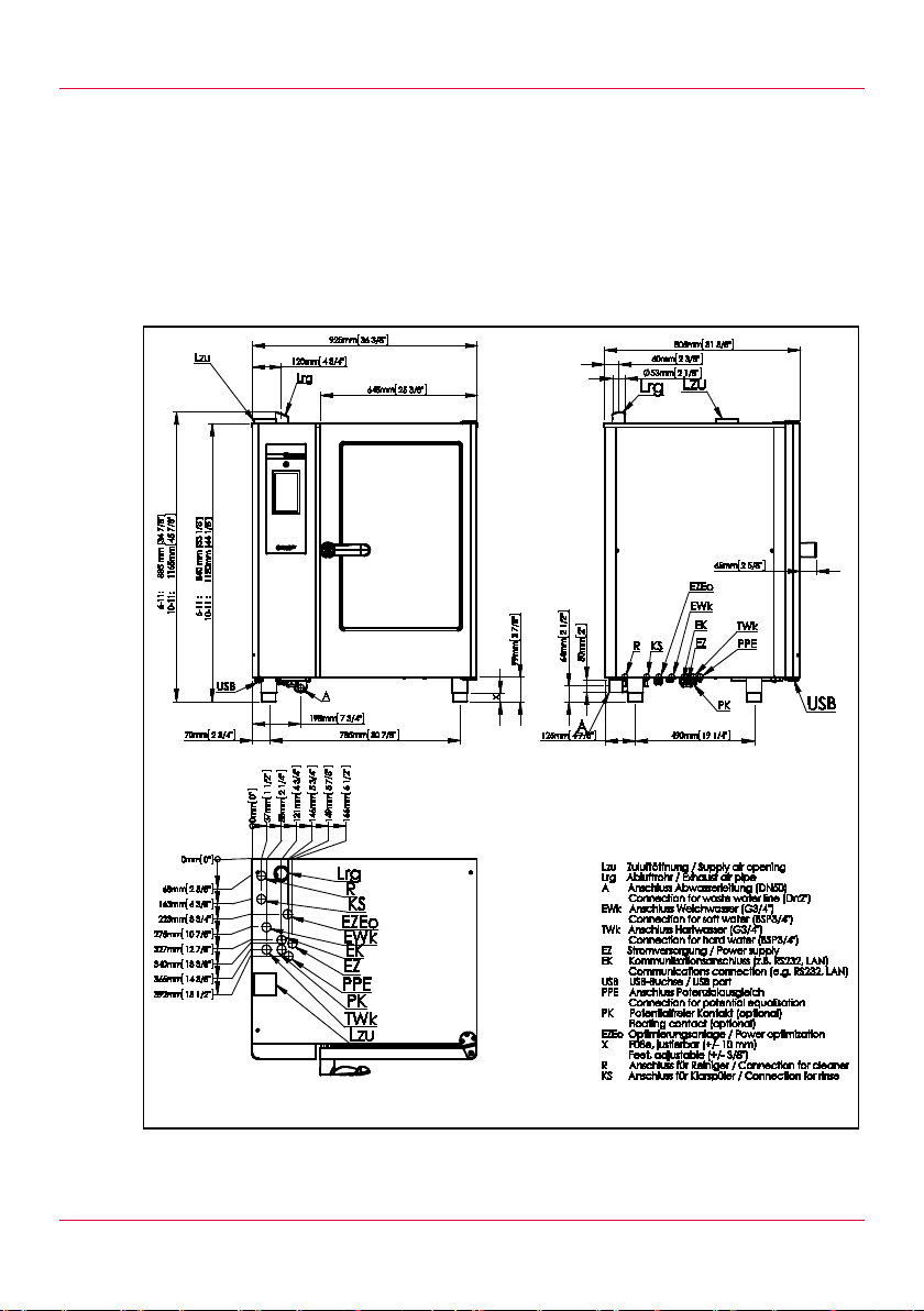
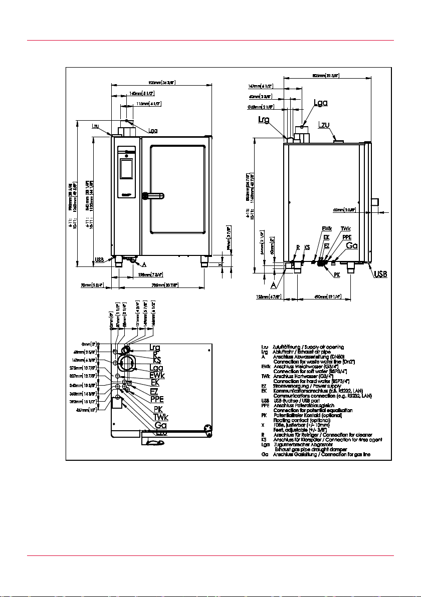
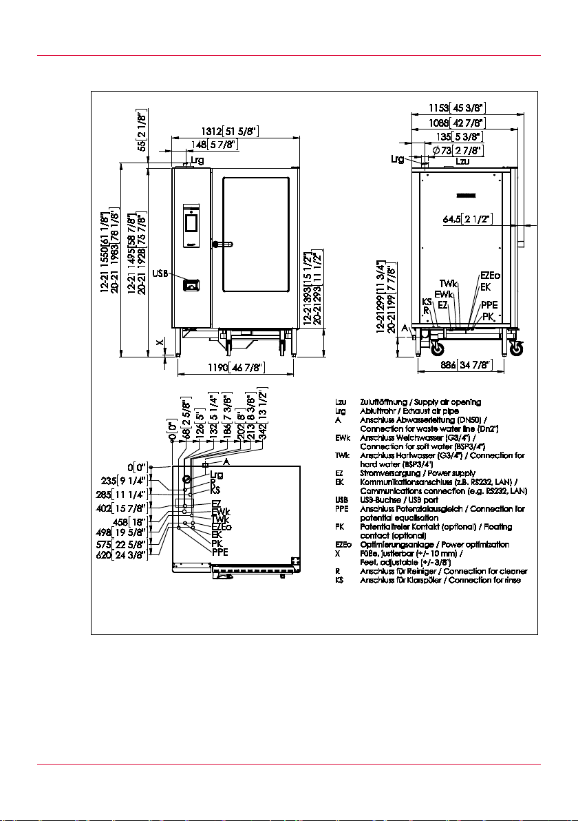
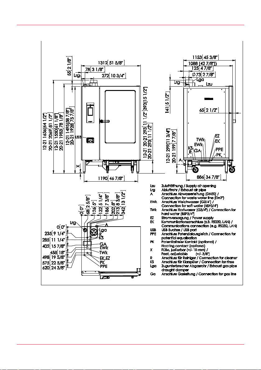
8 Dimension drawings
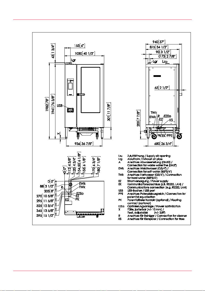
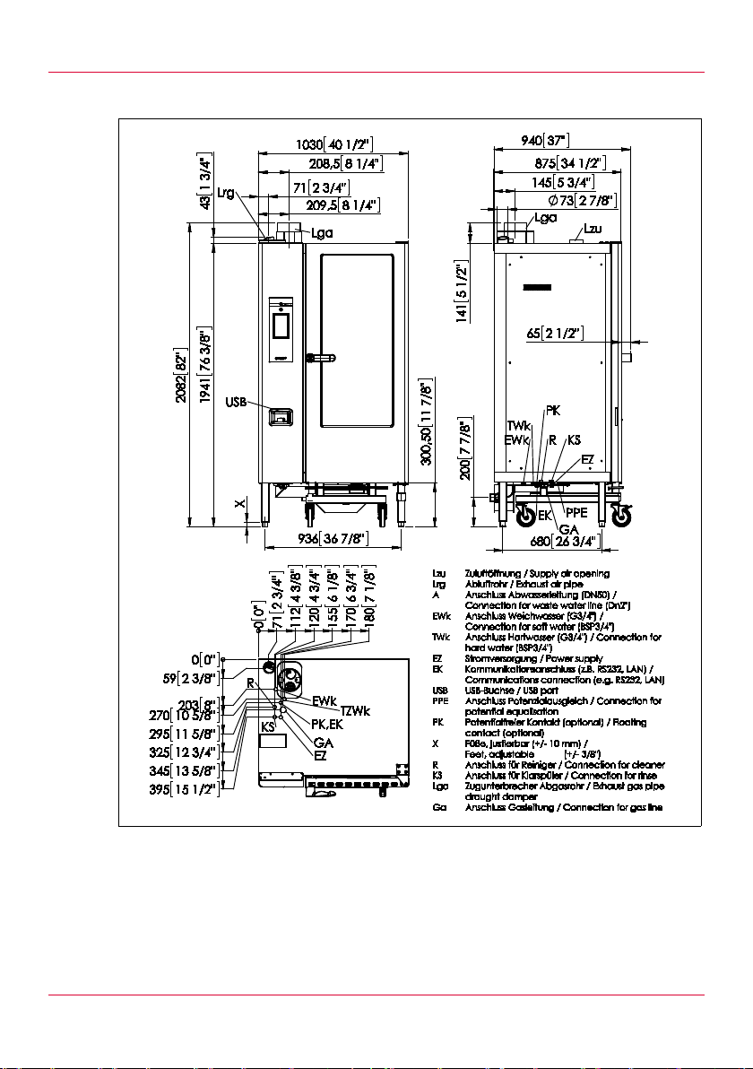
The dimension drawings appl y to appliances with doors hinged on the
right. For applianc es with door hinged on left: the dimension drawing i s a
mirror image of that shown here.
8.1 Dimension drawin g: Siz e 6-11 and 10-11, electric
40
Fig. 7: Size 6-11 and 10-11, electric, right hinged
Page 41
Dimension drawin gs
8.2 Dimension drawin g: Siz e 6-11 and 10-11, gas
Fig. 8: Size 6-11 and 10-11, gas, right hinged
41
Page 42
Dimension drawin gs
8.3 Dimension drawing: Size 12-21 and 20-21, electric
42
Fig. 9: Size 12-21 and 20-21, electric, right hinged
Page 43
Dimension drawin gs
8.4 Dimension drawing: Size 12-21 and 20-21, gas
Fig. 10: Size 12-21 and 20-21, gas, right hinged
43
Page 44
Dimension drawin gs
8.5 Dimension drawing: Size 20-11, electric
44
Fig. 11: Size 20-11, electric, right hinged
Page 45
Dimension drawin gs
8.6 Dimension drawing: Size 20-11, gas
Fig. 12: Size 20-11, gas, right hinged
=== Ende der Liste für Textma rke Inhal t6 ===
45
Page 46

Dimension drawin gs
46
Page 47

ins_EL2000885_ge_m_v03_en | 06/2014
Eloma GmbH . Innovative Koch- & Backtechnik
 Loading...