

Page 1

Xpressive II
07.10.2005
Elna International Corp. SA
User’s Guide
Page 2

COPYRIGHT
© Copyright 2005 Pulse Microsystems Ltd. All rights reserved.
This Xpressive User’s Guide and the Xpressive software are copyrighted by the deve l-
oper of the software, Pulse Microsystems Ltd. Al l rights reserved. US Patent Nos. 5 270
939; 5 343 401; 5 430 658; 5 506 784; 5 510 994; 5 541 847; 5 668 730; 5 771 173; 5
809 921; 6 196 146; 6 216 618; 6 390 005. European Patent Nos. 0545773. Other patents pending.
Information in this document is subject to change without notice.
The software described in this document is furnished under a license agreement and/or
nondisclosure agreement. The software may be used or copied only in accordance
with the terms of those agreements. No part of this publication and the software may be
copied, photocopied, reproduced, translated, or reduced to any electronic medium or
machine-readable form without the manufacturer’s written permission.
Commercial or industrial use of trademark and copyrighted works (For example, books,
paintings, drawings, photos, fanciful characters, and so forth) owned by other companies or persons, for creation of embroidery patterns without permission is illegal and
may result in either criminal or civil liability.
Microsoft and Windows®2000/XP are registered trademarks of Microsoft Corporation.
All other product names are copyrighted and registered trademarks or trademarks of
their respective holders. All computer and software names identified by TM or tm are
trademarks of their respective manufacturers.
Page 3

Table of Contents
Chapter 1 Getting Started
The Xpressive package ............................................................. 10
System Requirements......................................................... 10
Backing up files ................................................................... 10
Connecting Hardware................................................................ 10
Connecting the Elna embroidery machine ...........................11
Configuring the Elna embroidery machine ...........................11
Installing Xpressive.....................................................................11
Using other disk formats................................ ... ... .... ... ... ... ... .......11
Registering Xpressive.................................................................11
Obtaining a License for Xpressive from the Internet ........... 12
Obtaining a License for Xpressive without Internet Access. 13
Transferring a License from a Second Computer................ 15
Opening and Closing Xpressive................................................. 18
Calibrating your Screens for Accurate Measurements .............. 19
ELNA XPRESSIVE II 1
User’s Guide
Chapter 2 Setting up Xpressive
Setting up the workspace environment...................................... 22
Showing and hiding toolbars...... .... ... ... ... .... ... ... ... .... ... ............... 22
Showing and hiding the draw ribbon....... .... ... ... ... .... ... ... ... ....... .. 23
Customizing the draw ribbon ..................................................... 23
Setting user preferences............................................................ 23
Chapter 3 Learning the Basics
Understanding the Xpressive Workspace.................................. 26
Title Bar............................................................................... 26
Menu Bar............................................................................. 26
Status Bar......... ... .... ... ... ... ... .... ... ......................................... 26
Xpressive Tools ................................................................... 26
Tools on the Ribbon............................................................. 26
Draw Ribbon Tools .............................................................. 28
Editing Tools........................................................................ 29
Viewing Tools....................................................................... 30
Stitch Edit Tools................................................................... 30
Page 4

2
Lettering Tools..................................................................... 30
Punching Tools.................................................................... 31
File Tools ............................................................................. 31
Correcting mistakes................................................................... 32
Creating new designs ................................................................ 32
Entering measurements............................................................. 32
Opening and closing designs..... ................................................ 32
Opening designs using the Library feature.................... ... ......... 34
Saving designs........................................................................... 35
Saving a Copy of a Design ........................................................ 36
Setting up design worksheets.................................................... 36
Using the scroll bars .................................................................. 37
Working with Thread Charts ...................................................... 38
Changing the colors in designs ........................................... 38
Adding custom thread colors to a custom thread chart....... 39
Adding standard thread colors to a custom thread chart..... 39
Choosing a thread chart...................................................... 40
Changing the thread chart................................................... 40
Removing a thread color from the custom thread chart...... 40
Removing all threads in the custom thread chart................ 40
Printing Designs...................................... .... ... ... ... .... ... ............... 41
Changing a design’s print settings....................................... 41
Previewing a design before printing.................................... 42
Printing design worksheets......................................... ... .... .. 42
Printing in 3D View.............................................. ... ... ... .... .. 42
Inputting and Outputting Designs............................................... 43
Inputting a design................................................................ 43
Outputting a design ............................................................. 43
Outputting a design to the Elna embroidery machine ......... 45
Chapter 4 Viewing and Measuring Designs
Viewing Methods and Tools ....................................................... 48
Magnifying and reducing the view....................................... 48
Viewing designs................................................................... 48
Viewing the actual size of designs....................................... 49
Viewing the whole design on-screen................................... 49
Viewing a design selection on-screen................................. 50
Viewing parts of a design not visible in the design
workspace ........................................................................... 50
Viewing Buttons......................................................................... 50
Changing the background color of the current window ....... 50
Page 5

ELNA XPRESSIVE II 3
User’s Guide
Showing and hiding outline segments................................. 50
Showing and hiding machine commands............................ 51
Showing and hiding the stitch placements in designs......... 51
Showing and hiding beads...................... ... ... .... ... ... ... ... .... .. 52
Showing and hiding stitches in design files......................... 52
Defining grid settings........................................................... 53
Showing and hiding grids..................... ... ... ... .... ... ... ... ... .... .. 54
Showing and hiding 3D stitches ......................................... 54
Viewing the sewing order of designs................................... 54
Viewing Commands................................................................... 55
Displaying a hoop while designing ...................................... 55
Finding potential stitch problems......................................... 56
Hiding outlines in design files.............................................. 56
Setting the 3D View options ............................................... 56
Viewing a design by thread color order............................... 57
Aligning and Measuring Designs ............................................... 57
Adding guidelines................................................................ 57
Moving guidelines............. ... .... ... ......................................... 58
Changing the ruler origin..................................................... 58
Defining ruler units............................................................... 58
Measuring designs.............................................................. 59
Chapter 5 Creating Lettering and Merging Designs
Creating Embroidery and TrueType® Lettering ......................... 62
Creating lettering using the Text tool ................................... 62
Creating horizontal lettering................................................. 62
Creating circle lettering........................................................ 63
Converting TrueType® lettering to Satin stitches................ 64
Inserting color changes................. ... .... ... ... ... .... ... ... ... ......... 65
Kerning the space between letters...................................... 65
Modifying Text segments..................................................... 67
Drawing mode for lettering .................................................. 68
Merging Designs........ .... ... ......................................................... 69
Merging designs with lettering............................................. 71
Chapter 6 Changing your Segment Settings
Changing the settings of a segment .......................................... 75
Changing Text properties............................................ ... ... ... .... .. 75
Choosing an embroidery font .............................................. 75
Choosing a TrueType® font................................................. 76
Choosing the Fill type for TrueType® lettering.................... 76
Page 6

4
Changing the shape of lettering manually........................... 76
Changing the vertical position of lettering ........................... 78
Changing the size and position of circle lettering................ 79
Rotating lettering manually.................................................. 81
Changing the shape of lettering .......................................... 82
Setting the lettering height................................................... 82
Setting the justification ........................................................ 82
Setting lock stitches for lettering.......................................... 83
Changing Satin properties ...... ............................................. .... .. 84
Selecting a Fill pattern for Satin stitches ............................. 84
Setting the density for Satin stitches ................................... 84
Changing Satin Effect properties................................ ... ... ... .... .. 85
Applying a jagged effect to Satin stitches...................... .... .. 85
Changing Run properties........... .... ... ... ... .... ... ... ... .... ... ... ... ... ...... 86
Choosing a style for Run stitches........................................ 86
Setting the stitch length for Run stitches............................. 86
Changing Steil properties.................................. ... .... ... ... ... ... .... .. 87
Setting the width for Steil stitches........................................ 87
Changing Complex Fills properties............................................ 87
Adjusting the stitch length for the selected Fill pattern........ 87
Selecting a pattern for Fills.................................................. 87
Setting the stitch density for Fills......................................... 88
Changing Carved Fill properties ................................................ 89
Choosing a Carved Tile pattern........................................... 89
Creating Carved Fills........................................................... 89
Changing Programmed Fill properties..................................... .. 91
Adjusting the stitch length for Programmed Fill patterns..... 91
Choosing a Programmed Fill pattern................................... 91
Changing Pull Compensation properties ................................... 92
Adjusting pull-compensation ............................................... 92
Changing Underlay properties....................................... ... ... .... .. 92
Selecting the underlay type................................................. 92
Changing the inset distance.............................................. .. 93
Increasing the number of lines for perpendicular under lay. 93
Specifying the underlay density........................................... 94
Specifying the underlay stitch length................................... 94
Changing Commands properties...................................... ... .... .. 94
Adding machine commands................................................ 94
Applying lock stitches.............................................. ... ... .... .. 95
Changing a thread color number......................................... 96
Page 7

Chapter 7 Design Editing in Stitch Mode
Editing Stitches and Stitch Groups............................................. 98
Selecting stitches in various ways....................................... 98
Deleting stitches.................................................................. 99
Flipping stitches in a design file......................................... 101
Mirroring stitches in a design file....................................... 102
Moving through Stitch designs .......................................... 103
Moving stitches in a design file......... .... ... ... ... .... ... ... ... ... .... 105
Moving or copying stitches................................................ 105
Resizing stitches in a design file ....................................... 107
Rotating stitches in a design file.................... .... ... ... ... ... .... 109
Editing Stitches.........................................................................110
Adding a trim ......................................................................111
Changing thread colors in design files ...............................111
Changing existing machine commands..............................113
Inserting a stitch ............ ... ... .... .......................................... .114
Chapter 8 Design Editing in Outline Mode
Editing Segments......................................................................116
Selecting segments............................................................116
Converting stitches to outline segments .............................118
Converting stitches to stitch segments...............................118
Deleting segments..............................................................119
Moving through Outline designs.........................................119
Reflecting segments.......................................................... 121
Resizing segments............................................ ... ... ... ... .... 122
Rotating segments............................................................. 124
Closing Open Segments.................................................... 125
Copying segments................................................................... 125
Copying segments using the Clipboard............................. 125
Moving segments. ............................................. ... .................... 126
Moving segments manually........................ ... .... ... ... ... ... .... 126
Moving segments using Power Edit .................................. 126
Moving segments using the Clipboard .............................. 127
Nudging segments ............................................................ 128
Sequencing Outline Segments ................................................ 128
Inserting segments earlier in the segment sequence........ 128
Inserting segments later in the segment sequence........... 129
Moving a segment backward or forward ........................... 130
Moving a segment to the start or end of a design ............. 132
Locking Segments in Sequence View............................... 135
ELNA XPRESSIVE II 5
User’s Guide
Page 8

6
Resequencing by color..................... .... ... ... ....................... 136
Chapter 9 Using Paths
Drawing Lines...................................... ... .... ... ... ... .... ................ 138
Forcing horizontal and vertical lines.................................. 139
Drawing diagonal lines.................. ... .... ... ... ... .... ... ... ... ... .... 140
Drawing mode for lettering ................................................ 140
Drawing modes for punching......... ... .... ... ... ... .... ... ... ... ... .... 141
Drawing straight lines........................................................ 141
Vertex and Point Editing........................................................... 142
Adding and deleting anchor points.................................... 142
Changing the properties of an anchor point ...................... 142
Moving anchor points.................... ... .... ... ... ... .... ... ... ... ... .... 143
Resetting Handles............................................................. 144
Working with Beads....................................... ... ... .... ... ... ... ... .... 144
Different bead types .......................................................... 144
Changing the location of start and stop points .................. 144
Adding angle lines to segments......................................... 145
Chapter 10 Working with Images
Scanning images ..................................................................... 148
Loading images for punching..... .............................................. 148
Rotating scanned images ........................................................ 149
Resizing scanned images....... ... .... ... ... ... .... ... ... ... .... ... ... ... ... .... 151
Removing scanned images.................................. .... ... ... ... ... .... 152
Hiding and showing images..................................................... 153
Lightening images.................................................................... 153
Auto Tracing Images................................................................ 153
Chapter 11 Using Punching Tools
Common embroidery stitch types ............................................ 156
Digitizing tips............................................................................ 157
Embroidery........................................................................ 158
Other items to consider ..................................................... 158
A successful digitizer......................................................... 158
Manual and Run Stitches......................................................... 158
Creating Bean stitches ...................................................... 158
Creating Manual and Jump stitches.................................. 159
Creating Run stitches........................................................ 160
Creating Two-Ply stitches.................................................. 160
Page 9

Satin and Fill Stitches........................................................... .... 161
Creating Satin or Fill stitches with the Enhanced
Column tool ................ ... ... ... .... ... ... ... .... ... ... ....................... 161
Creating Satin or Fill segments with holes ........................ 161
Creating stitches with the Complex Fill tool....................... 163
Creating Steil stitches........................................................ 164
Adjusting Satin and Fill Stitches............................................... 164
Changing the angle lines in Complex Fill segments ... ... .... 164
Appliqué................................................................................... 165
Creating an appliqué border.............................................. 165
Programmed Runs.. ............................................. .... ... ... ... ... .... 165
Using Programmed Runs.................................................. 165
Carved Fills.......... ... ... .... ... ... .................................................... 166
Applying Carved Fills to TrueType® lettering.................... 166
Chapter 12 Using Autodigitizing and Cross-Stitch Wizards
Using the Autodigitizing Wizard............................................... 168
Creating a New Xpressive Cross-Stitch Design....................... 169
Selecting an Image............................................................ 170
Color Reductions............................................................... 171
Transforming an Image ..................................................... 173
Image Edit.................. .......................................... ... ... ... .... 177
Adding Outlines to an Image............................................. 179
Final Preview..................................................................... 181
ELNA XPRESSIVE II 7
User’s Guide
Appendix A Keyboard Shortcuts and Commands
Keyboard Shortcuts ... .... ... ... ............................................. ... .... 184
Keyboard Commands.................................... ... ... .... ... ... .......... 186
Appendix B Getting Help
Xpressive documentation......................................................... 190
Using the Xpressive online Help.............................................. 190
Opening the online Help.................................................... 190
Using the Contents........................... .... ... ... ... .... ................ 191
Using the Index ................................ .... ... ... ... .... ... ... ... ... .... 191
Using Search.................... ... .... ... ... ... .... ... ... ....................... 191
Using the Font Help........................................................... 192
Using the Fill Help................... ... ... ... .... ... ... ... .... ... ............. 192
Saving your favorite topics ................................................ 192
Printing online Help topics................................................. 192
Page 10

8
Glossary....................................................................................195
Index..........................................................................................221
Page 11

CHAPTER 1
Getting Started
Welcome to the Xpressive II embroidery design system for the Elna
home-based embroidery machine. The Xpressive
provides you with the information you need to install the software
and hardware and to learn about Xpressive.
Before you begin, you should be familiar with basic
Windows®2000/XP usage and conventions. To learn more about
Windows®2000/XP, see the Windows online Help.
In this chapter:
• Find out what you receive in the Xpressive package.
• Learn how to connect the Elna machine to your computer.
• Learn how to install the Xpressive software.
User’s Guide
II
Page 12

10
The Xpressive
package
We recommend that you follow the
procedures outlined in the Getting
Started Guide to ensure that you install
Xpressive correctly.
Each Xpressive package includes the
following components:
• Xpressive Getting Started Guide.
• Xpressive User’s Guide.
• Xpressive CD-ROM.
System Requirements
Specifications are subject to change
without prior notice. For additional
information on setup and system
requirements, contact your distributor.
Minimum Recommended System
Requirements:
• Genuine Intel Pentium 4, 2GHz PC
computer (or higher) with a CD-ROM
drive
• 17" or 21" monitor with 1024x768 video
resolution with 16-bit color display (or
higher).
• 256 megabytes of RAM
• Microsoft® Windows®2000/XP operating
system
• 3.5-inch high-density disk drive for most
disk formats
• Minimum 1 gigabyte hard disk drive
space available
• Mouse (3 button is preferred for punching)
Backing up files
If Microsoft Backup is not currently
installed on your computer, refer to the
Windows®2000/XP online Help fo r
installation instructions.
Windows®2000/XP comes with an efficient
file Backup program called Microsoft Backup.
We recommend you use Microsoft Backup to
backup files and designs on a regular basis.
Backing up your work protects your designs
in case the data on your computer is lost or
damaged.
To back up files:
1 Click Start.
2 Choose Programs—Accessories—System
Tools—Backup.
3 Follow the instructions provided.
If you have any problems, consult the
Microsoft Backup’s online Help.
Connecting Hardware
You can now set up all the hardware you
want to use with Xpressive. This section
describes how you can connect these
devices. The most important device is the
Elna embroidery machine.
Xpressive supports many different peripheral
devices. The most important device you need
to connect is your Elna embroidery machine.
First, you need to connect the peripheral
devices to the ports at the back of your
computer. Then, when you install Xpressive,
these hardware components are configured
to run with Xpressive.
Page 13
Connecting the Elna
embroidery machine
We recommend that your embroidery
machine settings be configured using the
Xpressive Installation.
Serial embroidery machines are configured
during the Xpressive installation once the
machine’s hardware has been set up.
To connect the Elna embroidery
machine:
1 Use the Elna documentation to set the
correct port settings.
2 Connect the machine to an available
serial port on the computer using the
serial cable provided with Xpressive.
3 Turn on your computer.
Now, when you install Xpressive, the
machine settings will be set accordingly.
Configuring the Elna
embroidery machine
See the Elna documentation for more
information on how to set up the Elna
embroidery machine.
Installing Xpressive
Y ou must be runni ng Windows®2000/XP
to install Xpressive.
ELNA XPRESSIVE II 11
User’s Guide
2 Click Next to follow the installation.
3 Follow the instructions on each screen.
Using other disk
formats
Xpressive supports other disk formats such
as Elna, Tajima, Pfaff, and Brother, Pfaff,
Janome, Viking, Poem, and Singer.
Registering Xpressive
Initially you can use the Xpressive software
for up to 30 days without a license. To use it
in this 30-day trial mode, select this option
when you install the program. Each time you
run the program the remaining number of
days in the trial period will be displayed.
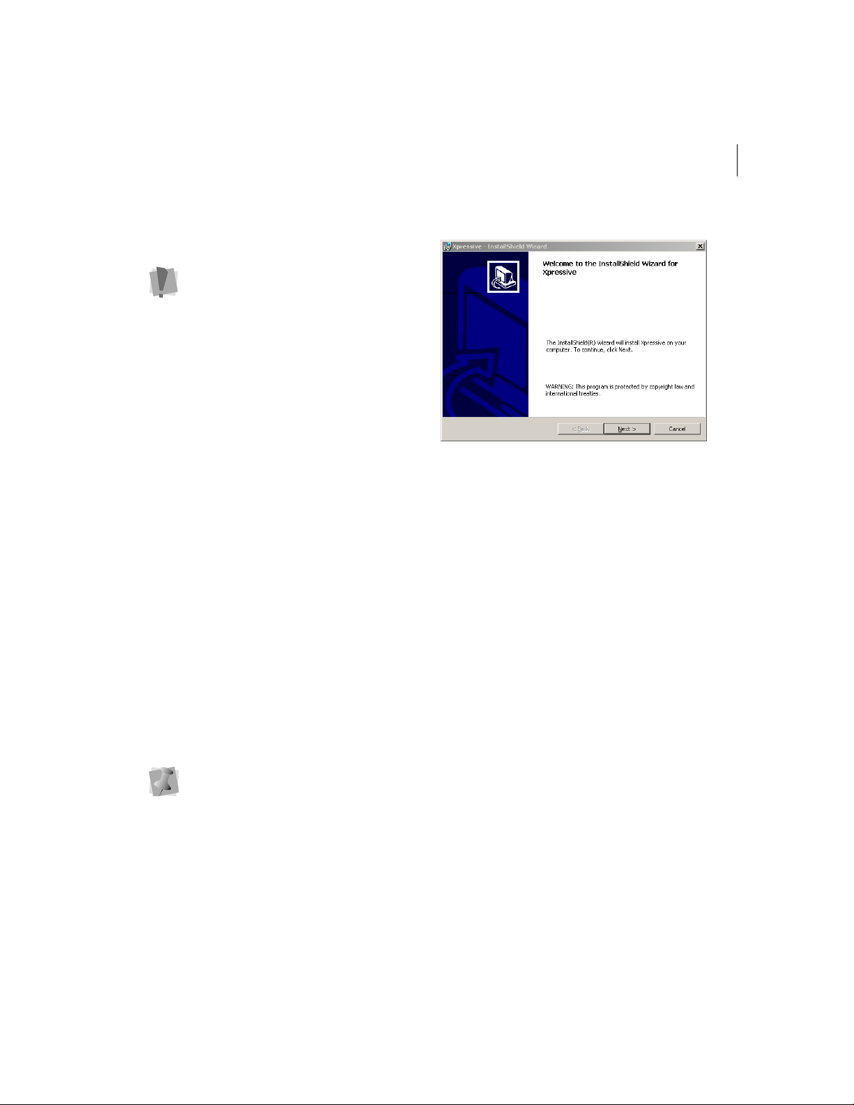
To install Xpressive:
1 Insert the Xpressive CD into the CD-
ROM drive.
You see the InstallShield introductory
screen.
Page 14
12
Any time during the evaluation period you
can start the registration using the Help
menu. You can choose one of the following
options to obtain a license:
• U sing a serial number (requires Internet
connection).
• Providing an unlocking key given to you
by phone or e-mail.
• Transferring a license from another
computer.
Obtaining a License for
Xpressive from the
Internet
If you received a product serial number with
the program, the number can be used to
obtain a license. If you have an Internet
connection, you can have the program
automatically obtain a license.
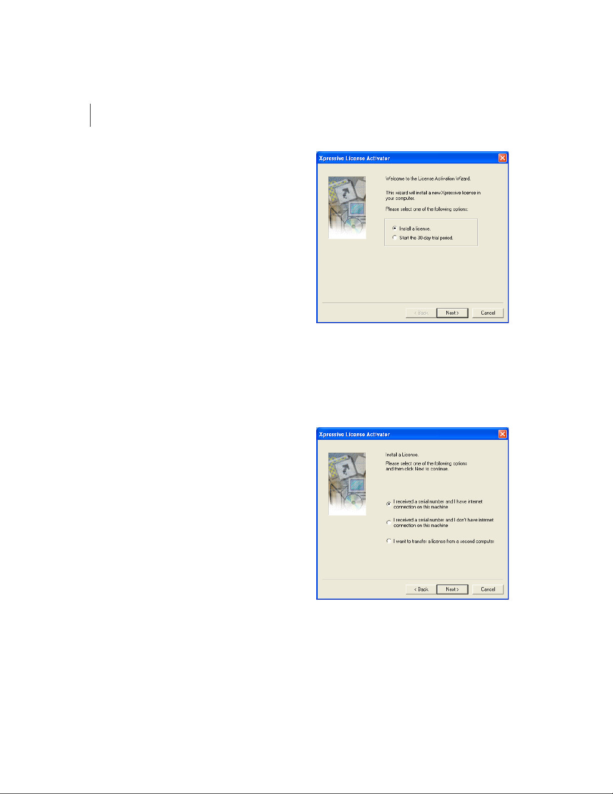
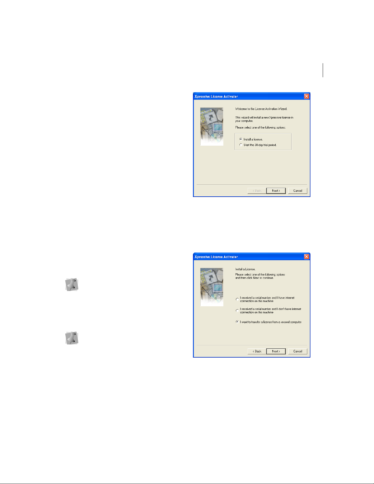
2 Select the Install a license option and
click Next.
You will see another Xpressive License
Activator wizard page appear.
To obtain a license from the Internet:
1 To open the Xpressive License Activator
wizard, select one of the following
procedures:
If you are using the 30-day trial mode
for Xpressive, choose Help—Open
License Activator.
If your 30-day trial mode has expired,
double-click the Xpressive link on your
computer desktop.
You will see the Xpressive License
Activator wizard appear.
Page 15
3 Select I received a serial number & I have
an internet connection on this machine
and click Next.
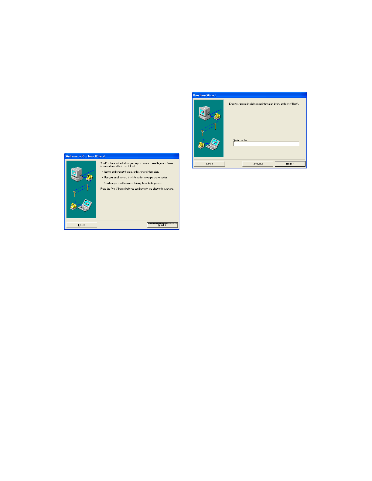
You will see the Welcome to Purchase
Wizard page appear.
ELNA XPRESSIVE II 13
User’s Guide
5 In the Serial number field, enter the serial
number you received and click Next.
You will see another Purchase Wizard
page appear.
6 To finish obtaining a license for Xpressive,
click Finish.
4 Read the information shown and click
Next.
You will see the Purchase Wizard page
appear.
Obtaining a License for
Xpressive without Internet
Access
If you do not have an Internet connection,
you will need to contact your dealer or
distributor to obtain a license. Please refer to
the contact information that you received with
your package.
To obtain a license without Internet
access:
1 To open the Xpressive License Activator
wizard, select one of the following
procedures:
If you are using the 30-day trial mode
for Xpressive, choose Help—Open
License Activator.
Page 16
14
If your 30-day trial mode has expired,
double-click the Xpressive link on your
computer desktop.
You will see the Xpressive License
Activator wizard appear.
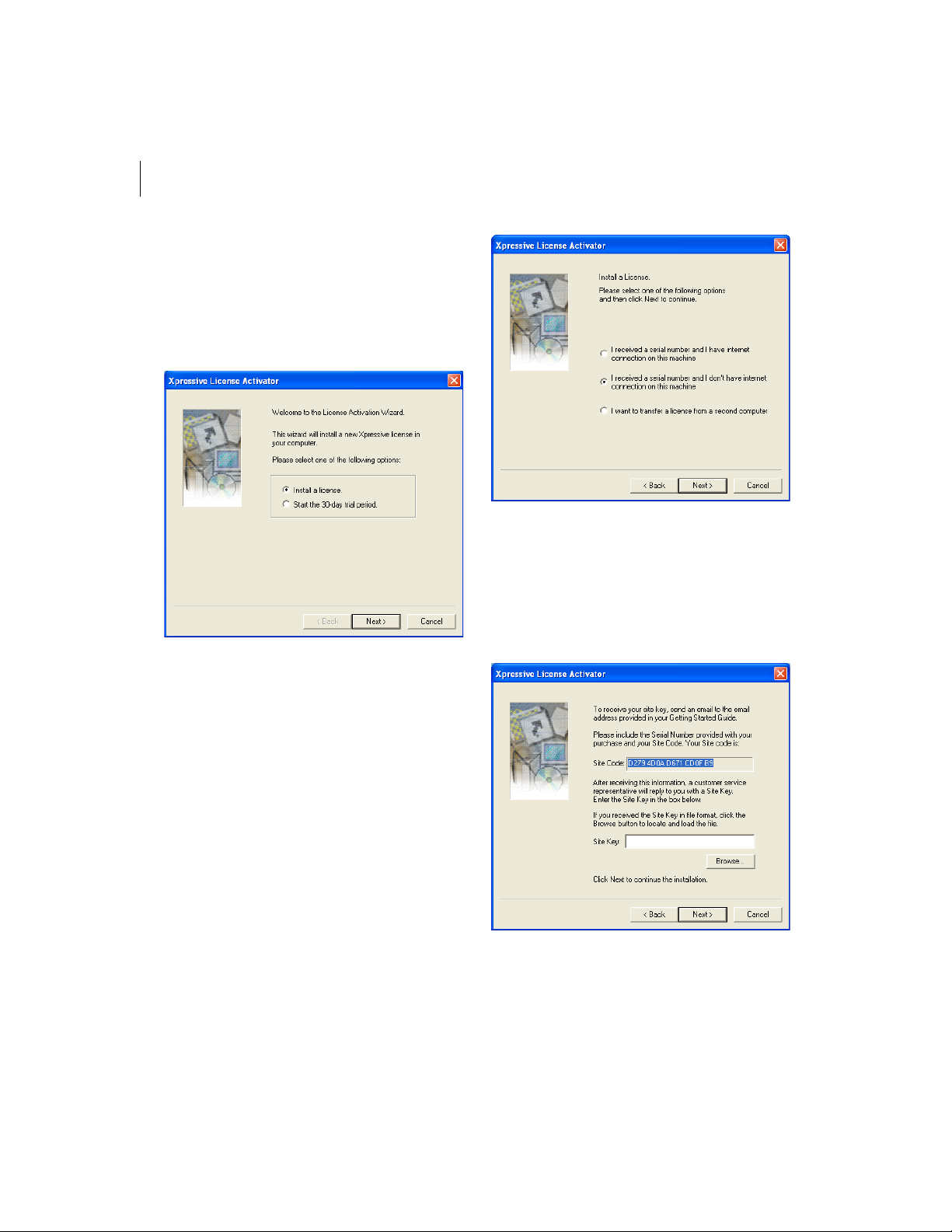
3 Select I received a serial number & I don’t
have internet connection on this machine
and click Next.
You will see another Xpressive License
Activator wizard page appear.
2 Select the Install a license option and
click Next.
You will see another Xpressive License
Activator wizard page appear.
Page 17
4 In the Site Key field, enter the site key you
were given for your computer or click
Browse and find the location of the site
key. Click Next to continue.
You will see another Xpressive License
Activator wizard page appear.
5 Click Next to continue.
You will see another License Activator
wizard page appear.
6 Click Finish to complete your installation.
Transferring a License
from a Second Computer
If you are running an installation of Xpressive
on your computer, without a license, you can
transfer an existing license from a second
computer. You can copy an Xpressive license
onto a floppy disk, USB device or network
directory folder. Only the Xpressive
installation with a lice nse can r un the
software.
ELNA XPRESSIVE II 15
User’s Guide
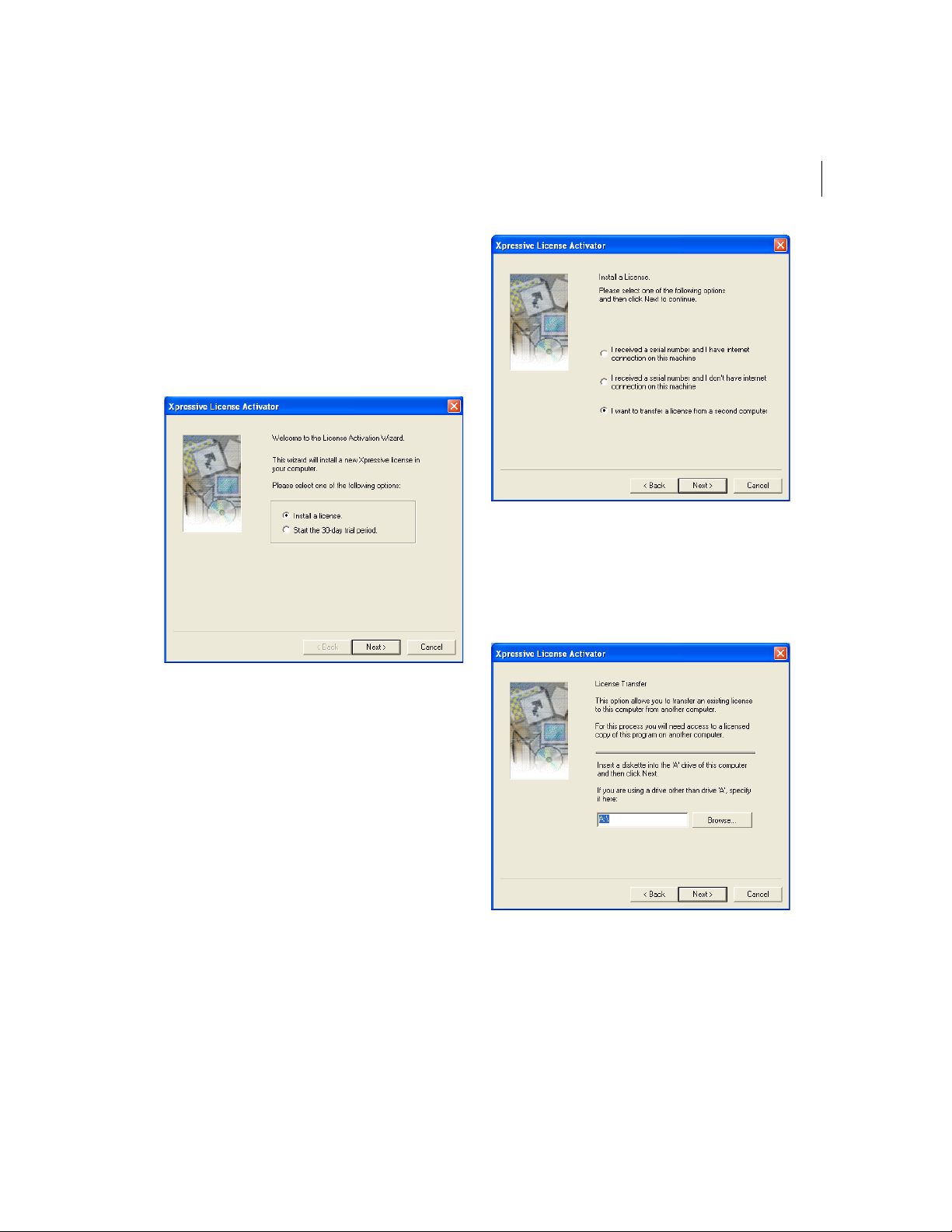
2 Select the Install a license option and
click Next.
You will see another Xpressive License
Activator Wizard page appear.
If you are using the 30-day trial, it is
considered a temporary license.
To transfer a license to a floppy disk:
1 On the computer without a license, open
Xpressive.
The first time you open Xpressive you
will see the License Agreement dialog.
To continue, click I agree.
You will see the Xpressive License
Activator wizard appear.
Page 18
16
3 Select I want to transfer a license from a
second computer and click Next.
You will see another Xpressive License
Activator wizard page appear.
9 Browse to your A:\ drive that contains
your floppy disk.
10 Click OK.
You see the License Transfer confirmation
dialogs. Click OK. Xpressive will
shutdown.
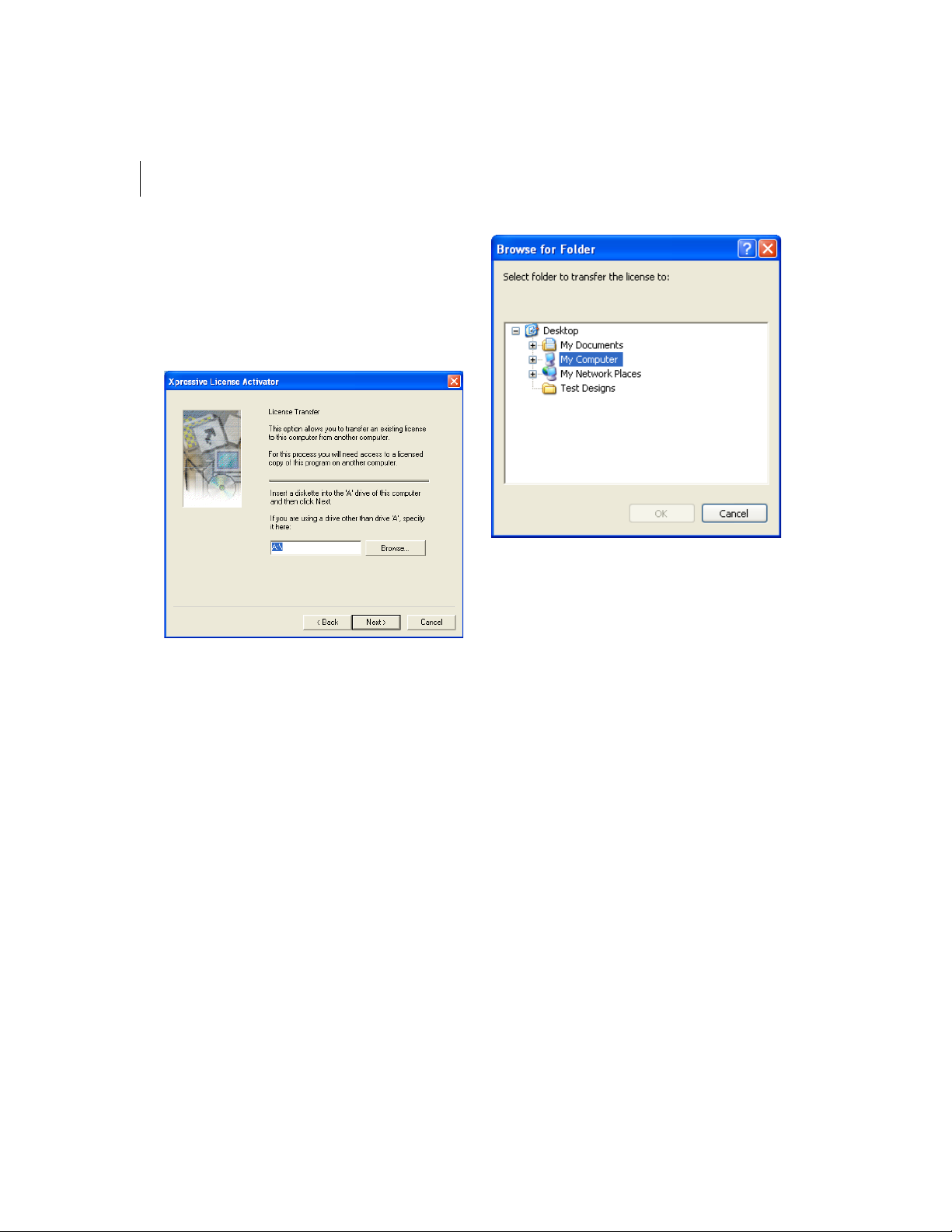
4 Insert an empty floppy disk into your A:\
drive.
5 Click Next and a registration file will be
copied to your floppy disk.
You will see another Xpressive License
Activator wizard page appear. Leave this
wizard page open.
6 Remove your floppy disk.
7 On the computer with a license, open
Xpressive and insert the floppy disk into
your A:\ drive.
8 Choose Help—Transfer License.
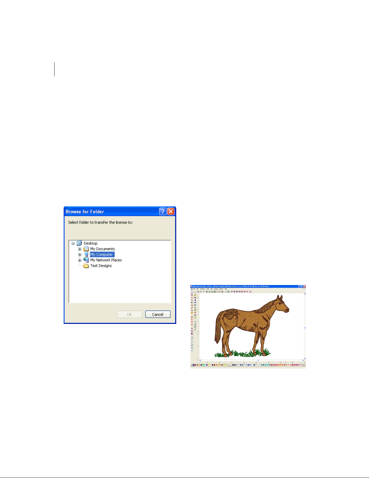
You will see the Browse for Folder dialog
The installation of Xpressive on this
computer will no longer have a license.
11 Remove your floppy disk.
12 On the computer without a license, insert
your floppy disk into the A:\ drive and
click Next.
The license will be copied to this
installation of Xpressive. You see another
License Activator wizard page appear.
13 Click Finish.
Xpressive will be launched. You can begin
using Xpressive on this computer.
appear.
Page 19
T o transfer a license t o directory or USB
device:
1 On the computer without a license, open
Xpressive.
You will see the Xpressive License
Activator wizard appear.
ELNA XPRESSIVE II 17
User’s Guide
3 Select I want to transfer a license from a
second computer and click Next.
You will see another Xpressive License
Activator wizard page appear.
2 Select the Install a license option and
click Next.
You will see another Xpressive License
Activator Wizard page appear.
Page 20
18
4 Click Browse and locate the network
directory you want to transfer your license
to.
5 Click Next.
You will see another Xpressive License
Activator wizard page appear. Leave this
wizard page open.
6 On the computer with a license, open
Xpressive.
7 Choose Help—Transfer License.
You will see the Browse for Folder dialog
appear.
The installation of Xpressive on this
computer will no longer have a license.
10 On the computer without a license, click
Next.
The license will be copied to this
installation of Xpressive. You see another
License Activator wizard page appear.
11 Click Finish.
Xpressive will be launched. You can begin
using Xpressive on this computer.
Opening and Closing
Xpressive
To open Xpressive:
• Do one of the following:
Double-click the Xpressive icon
created on your desktop.
Choose Start—Programs—Xpressive.
You will see the Xpressive window appear.
8 Browse to location of the specified
network directory or USB device you
want your license transferred to.
9 Click OK.
You see the License Transfer confirmation
dialogs. Click OK. Xpressive will
shutdown.
To close Xpressive:
• Choose File—Exit.
Page 21
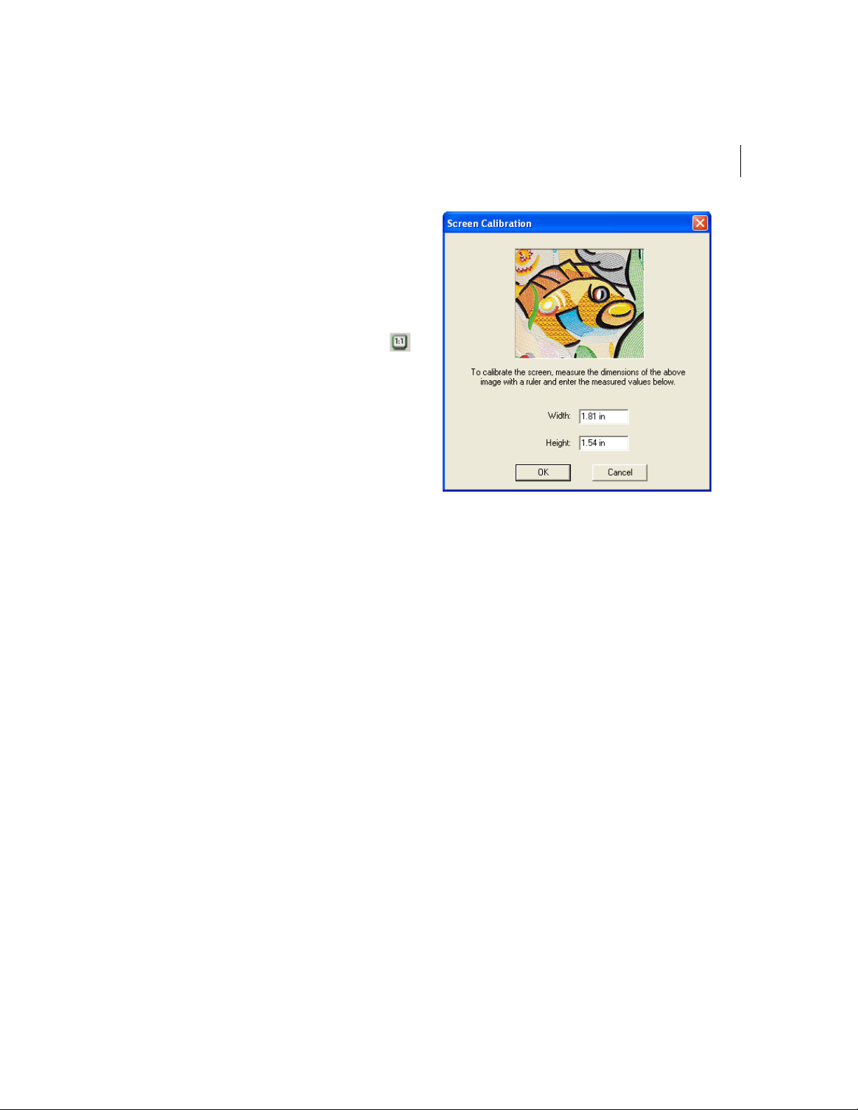
Calibrating your
Screens for Accurate
Measurements
Xpressive allows you to calibrate your
monitor to display design dimensions
accurately. When you use the Back to 1:1
tool, a tool used to display designs in their
original size, the ruler measurements will be
accurate and mat c h t h e n u m b e r o f
centimeters or inches that the design
measures.
To calibrate your screen:
1 Start Xpressive.
2 Choose Tools—Configuration—Calibrate
Screen...
You see the Screen Calibration dialog
appear.
ELNA XPRESSIVE II 19
User’s Guide
3 To calibrate the screen, place a ruler
against your monitor and measure the
dimensions of the image shown in the
dialog.
4 In the Width box, enter your width
dimensions for the image shown.
5 In the Height box, enter your height
dimensions for the image shown.
6 Click OK.
Page 22

20
Page 23

CHAPTER 2
Setting up Xpressive II
Elna Xpressive II allows you to arrange your toolbar in a way
that suits your needs. To set up Xpressive, you can change the
settings for user preferences such as Company Name and Units
of Measurement. Once Xpressive is set up to suit your needs, you
will find learning the basic components of the software a lot
easier.
In this chapter:
• Find out how to set up your workspace environment and user
preferences.
• Learn how to arrange your toolbars in a way that best suits
your needs.
Page 24
22
Setting up the
workspace
environment
The Xpressive workspace includes the
toolbars, menus, ribbon, and the design
window containing the design you are editing.
The way many of the tools work and the look
of the workspace is controlled in the
Environment Display user settings. You can
change the look and functionality of your
design workspace by changing these
settings. For more information on the design
workspace, see the section on
"Understanding the Xpressive Workspace".
Activate Auto-panning. When you
select Activate Auto-panning, the
system automatically pans for you
when you reach the edge of the
window while you are designing.
4 Click OK.
Showing and hiding
toolbars
You can hide or move a toolbar if it is
blocking your view of the workspace and
cluttering the screen. You can move the
toolbars anywhere on the screen. If you drag
a toolbar to the edge of the design
workspace, it attaches to the sides, top, or
bottom edge of the workspace. You can
arrange the toolbars in an order that is
comfortable for you. You can also leave
toolbars floating on your workspace.
To see the name of each tool on the
various toolbars, simply move your
pointer over the tools. A small Tool Tip
box pops up and displays the tool name.
To set up the workspace environment
display:
1 Choose Tools—Configuration—User
Settings.
You see the Settings property pages.
2 Click the Environment - Display property
page.
3 In the Tool button size box, choose Large
or Small button sizes for the toolbars.
To show or hide the toolbar:
1 Choose the toolbar you want to show or
hide from the Toolbars menu.
A check mark indicates that the toolbar is
visible on your screen.
2 To move the toolbars, drag the floating
toolbar by its title bar or drag by the gray
area around the buttons.
Page 25
ELNA XPRESSIVE II 23
User’s Guide
Showing and hiding
the draw ribbon
You can show or hide the draw ribbon. The
draw ribbon tools control which parts of the
design are drawn.
For more information on using Draw
Ribbon tools, see “Draw Ribbon Tools”.
To show or hide the draw ribbon tools:
• Click the Hide/Show tool.
Customizing the draw
ribbon
Xpressive makes it easy to customize draw
ribbon settings.
To customize the draw ribbon:
1 From the draw ribbon, click the draw
ribbon mode setting tool.
You see the Draw Ribbon Setting dialog
appear.
2 In the Draw Mode area, select one of the
following draw modes:
Normal. All stitches in the design are
drawn and the design window position
remains fixed.
Auto-pan. All stitches in the design
are drawn. While the design sews out,
the system automatically pans the
design each time it reaches the edge
of the window. This feature is useful if
you want to zoom in and see stitches
in more detail.
Only show stitches inside the
window. Only stitches displayed in
the design window are drawn and the
design window position remains fixed.
Inside the design window, you will
only see stitches being sewn for
visible areas of the design. This
feature is useful if you zoomed into a
specific area and only want to have
this area of your design drawn to save
time.
3 To show the design as gray until the
system sews each of its stitches in color,
click Show gray after active.
4 In the Stop at area, select one or more
machine commands you want the Play
backward one color button and Play
forward one color button to pause at as
the design sews out. For example, you
can enable the design to pause its
drawing whenever it encounters a Trim. If
you do not select any commands, the
design will pause at all color changes
while drawing.
5 Click OK.
Setting user
preferences
You can change user preferences such as
Language, Company Name, and Units of
measurement.
Y ou need to rest art Xpressive if you hav e
selected another language.
Y ou must have the p roper *.dll files to run
Xpressive in another language. Without
these files, the program will not run in the
language you choose.
Page 26

24
To set user preferences:
1 Choose Tools—Configuration—User
Settings.
You see the Settings property pages.
2 Click the User Preferences property page.
3 Select the following settings:
From the Language list, select the
language for Xpressive’s menus and
dialog boxes.
In the Company Name box, enter your
company’s name.
In the Units of measurement area,
select Metric or Imperial as your unit
of measurement.
4 Click OK.
Page 27
CHAPTER 3
Learning the Basics
Before you start using Xpressive, we recommend you learn a
few of the basics outlined in this chapter and then try the
lesson at the end of this chapter.
In this chapter:
• Learn basics such as how to start a new design, open and
close existing designs, and save designs.
• Find out how to set your preferences and use basic tools on
the design workspace.
• Learn how to print designs.
• Learn how to input and output designs.
Page 28
26
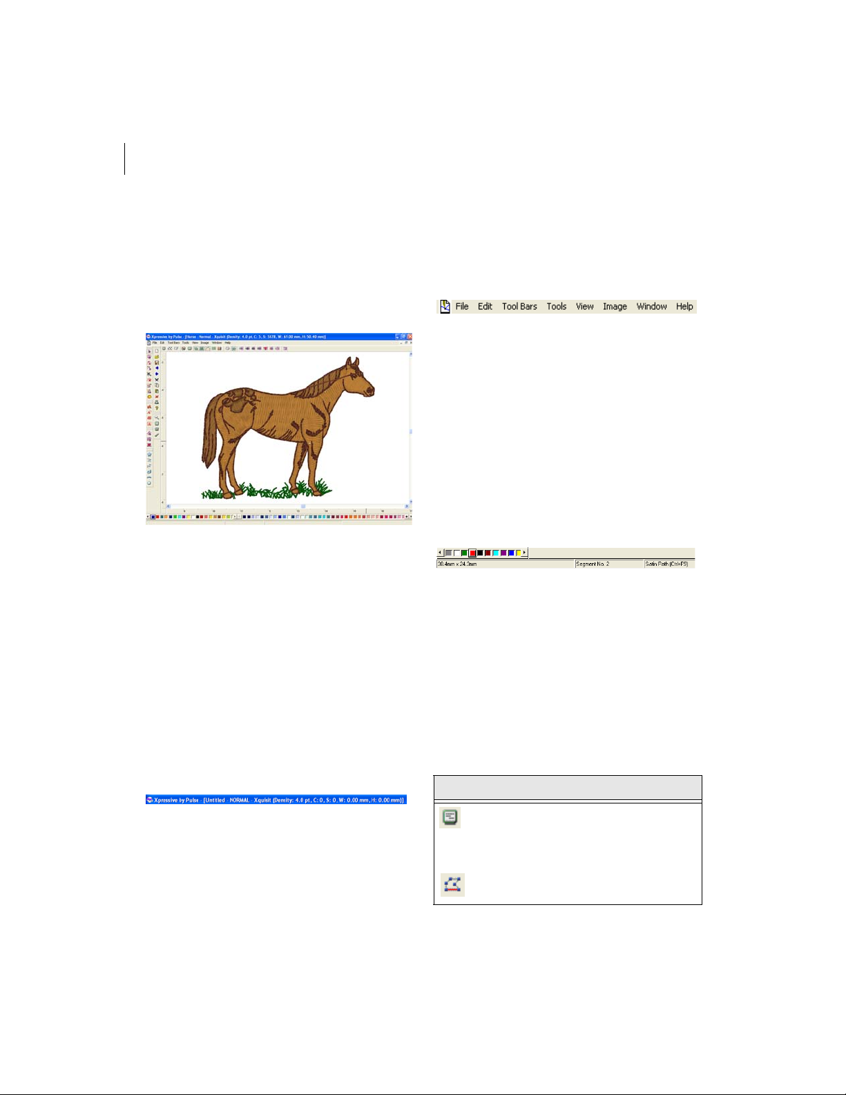
Understanding the
Xpressive Workspace
The Xpressive workspace contains several
areas. The screen below shows the
Xpressive workspace.
Title Bar
The Title Bar appears at top of the Xpressive
design window and the top of a minimized
design workspace. When you open a design,
the design’s name, recipe (style), machine
format settings, and design information are
displayed in the title bar. The number of
thread colors in a design as well as its stitch
count are automatically updated in the title
bar. A design’s stitch count is consistent with
the stitch count printed or sewn out using the
specified machine format settings.
Menu Bar
The Menu Bar appears below the Title Bar.
The Menu Bar contains a list of menus
specific to Xpressive.
Status Bar
The Status Bar appears at the bottom of the
Xpressive design window. On the left-side of
the status bar, the color palette shows the
thread colors used in the active design. You
will also find specific design information in
other areas of the status bar. For example,
the status bar shows the design dimensions
of the active segment or stitch, the scale of
zoom, the names of segments, etc.
Xpressive Tools
Xpressive has many tools available in the
Toolbar and on the ribbon of the design
window. The following charts describe the
tools specific to Xpressive.
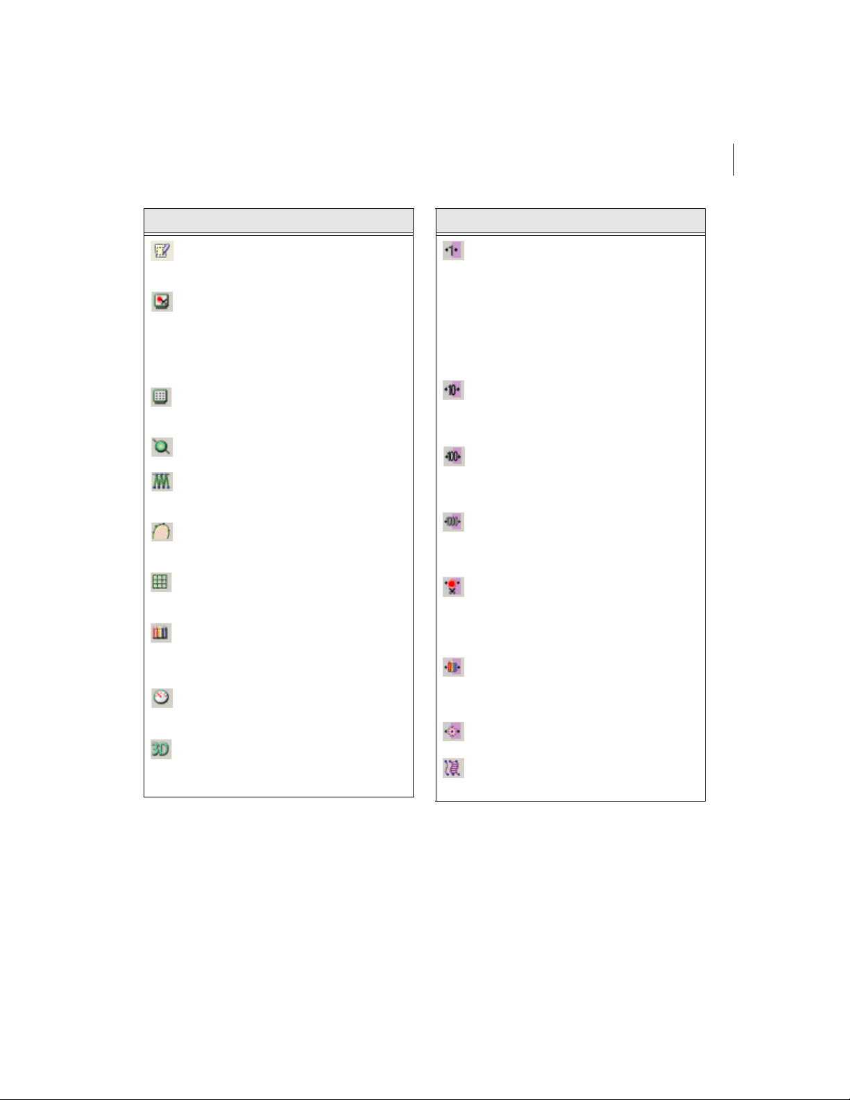
Tools on the Ribbon
Tool What it means
Segment Settings: Displays a
Segment Settings dialog that
allows you to view and change
segment settings.
Auto Close: Closes a segment
when punching.
Page 29
ELNA XPRESSIVE II 27
User’s Guide
Tool What it means
Autotrace: Detects contours and
traces an image to produce stitch
segments.
Show Commands: Shows
symbols at the locations on the
design where the embroidery
machine performs commands,
such as stop, trim, and
changeover.
Show Dots: Shows the stitch
penetrations represented by a
black dot.
Show Beads: Shows start, stop,
and angle line beads.
Show Stitches: Shows the
stitches of segments in the design
window (default setting).
Show outlines. Shows the outlines
of segments in the design window
(default setting).
Show Grid: Shows a background
grid to help you align anchor points
or measure a design.
Change Background Color:
Displays a color palette that allows
you to change the background
color of the window.
Hides/shows the draw ribbon:
Hides or shows the design draw
ribbon.
Show 3-D Stitches: Use to provide
a realistic view of your design and
give a better idea of how stitches
will look.
Tool What it means
Move by 1: Use to move backward
or forward through a design by 1
unit (segment or stitch).
Left-click the tool to move
backward through the design by 1
unit. Right-click to move forward,
by 1 unit, from the currently
selected stitch or segment.
Move by 10: Use to move
backward or forward through a
design by 10 units (segment or
stitch).
Move by 100: Use to move
backward or forward through a
design by 100 units (segment or
stitch).
Move by 1000: Use to move
backward or forward through a
design by 1000 units (segment or
stitch).
Move to Previous/Next
Command: (Only available in
Stitch Mode). Use to move the
stitch select pointer to the previous
or next command in a design.
Move to Previous/Next Color:
Use to change the selection to the
previous or next color change in
the design.
Move to Start/End: Use to mov e to
the start or end of the design.
Convert: Use to convert lettering
to segments or segments to other
stitch types.
Page 30
28
Draw Ribbon Tools
Draw Ribbon tools make it easy to see how
your design will sew out on-screen. You can
use the Draw Ribbon tools to eliminate
potential sewing problems.
When you click the tool on the ribbon,
the draw ribbon tools (scrollbar slider, sewing
simulator, and draw ribbon mode setting) will
appear on the ribbon of the design window.
The draw ribbon controls which parts of the
design are drawn. You can draw stitches
while the draw bar is active, as well as
commands and stitch dots when turned on.
When the draw ribbon is active, you can
not draw a full screen crosshair , selection
box, outlines or beads.
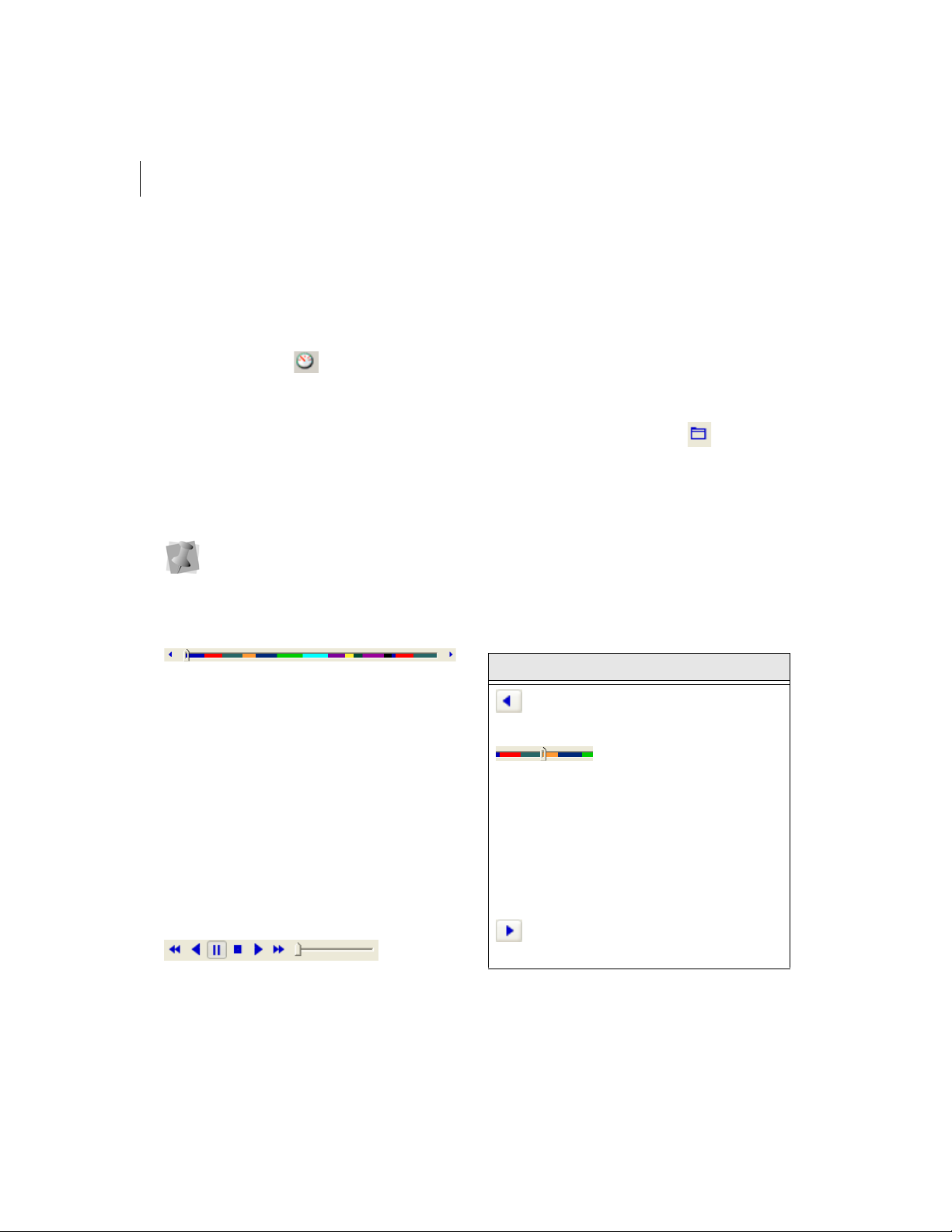
Scrollbar Slider
The length of the scrollbar slider represents
all of the stitches in the opened design. You
can move the scrollbar slider by dragging it to
see a design as it will look sewn to a
particular point. The color display within the
scrollbar indicates the thread color that will
be sewn when the scrollbar slider is
positioned over it. Clicking on the arrows at
the ends of the scrollbar will advance or
retrace the design position by one stitch.
Sewing Simulator
The sewing simulator allows you to watch
your design draw on a stitch-by-stitch basis,
simulating the sewing action of your machine.
The simulator controls are similar to a CD
player or VCR. You can push various control
buttons and slide the speed control to vary
the rate of sewing.
Draw Ribbon Mode Setting
The draw ribbon mode setting tool allows
you customize draw ribbon commands to suit
your needs. You can select various drawing
modes, show segments as gray after being
active and select commands that the sewing
simulator buttons will stop at.
Using Draw Ribbon Tools
The following table explains how to use the
draw ribbon tools in more detail:
Tools What is does
Play backward one stitch:
Move backward in the design
by one stitch.
Scrollbar slider: Drag the
scrollbar slider to advance the
design to a specific position.
When the scrollbar slider is
positioned over a color, you
will see the specified thread
color being sewn in the
design. The entire length of
the scrollbar slider represents
the entire design.
Play forward one stitch:
Move forward in the design by
one stitch.
Page 31

ELNA XPRESSIVE II 29
User’s Guide
Tools What is does
Play backward one color:
Move backward in the design
to the beginning of the
previous color or selected
command.
Play backward: Move
backward through the design.
Pause: Pause the design
while drawing. When you play
or resume sewing your
design, stitching will continue
from the location of the last
stitch.
Stop: Stop the design while
drawing.
Play forward: Move forward
through the design.
Play forward one color:
Move forward in the design to
the beginning of the next
color or selected command.
Speed Control: Slide the
speed control to vary the rate
of sewing.
Draw ribbon mode setting:
Use these settings to
customize draw ribbon
commands. You can select
draw modes, show segments
as being gray after being
active or select commands
that sewing simulator buttons
will stop at.
Editing Tools
Tool
What it
means
Select:
Selects
outline
segments.
Vertex
Select:
Selects
points and
individual
outline
segments,
allowing
for
advanced
editing.
Insert
Trim at
End:
Inserts
trim at the
end of
current
segment.
Tool
What it
means
Lasso
Select:
Selects
one or
more
outline
segments
to edit
(with a
polygon).
Angle
Lines:
Adds
angle
lines.
Delete
Outline:
Deletes
one
outline
point at a
time in
design
files.
Page 32

30
Tool
What it
means
Merge
Design:
Merges
existing
design file
with
another
design file.
Library:
Opens the
Library
window.
Viewing Tools
Tool
What it
means
Zoom:
Magnifies
the
design.
Fit to
Window:
Displays
the entire
design
and
loaded
images in
window.
Tool
Tool
What it
means
Backdrop
Select:
Selects
image files
to use as
backdrop
for onscreen
punching
or for auto
tracing.
What it
means
Back to
1:1:
Returns
design to
original
size.
Measure:
Measures
distance
between
parts of
design.
Stitch Edit Tools
Tool
What it
means
Stitch
Select:
Selects
stitches.
Delete
Stitch:
Deletes
one stitch
at a time
in design
files.
Tool
Lettering Tools
Tool
What it
means
Text:
Creates
lettering
placed
along a
baseline.
Line
Angle:
Creates
horizontal
lettering
that fills a
text box.
Tool
What it
means
Lasso
Stitch
Select:
Selects a
group of
stitches
to edit
(with a
polygon).
What it
means
Circle:
Creates
curved
lettering.
Page 33

Punching Tools File Tools
ELNA XPRESSIVE II 31
User’s Guide
Tool
What it
means
Enhanced
Column:
Creates
Satin or Fill
stitches by
traditional
punching
method.
Run:
Creates run
stitches.
Steil:
Creates steil
stitches.
Tool
What it
means
Manual:
Creates
manual and
jump
stitches.
Complex
Fill: Creates
a segment
filled with
Satin or
advanced
Fill stitching.
Appliqué:
Creates an
appliqué
border
around an
appliqué.
Tool
What it
means
New:
Creates a
new
untitled
design.
Save:
Saves
designs in
a variety
of file
formats.
Redo:
Reverses
the action
of the
Undo
command.
Copy to
Clipboard:
Copies the
selection
to the
clipboard.
Clear:
Clears the
current
selection.
Contents:
Opens the
online help
window.
Tool
What it
means
Open:
Opens an
existing
design file.
Undo:
Reverses
your last
action.
Cut to
Clipboard:
Cuts the
selection
and copies
it to the
clipboard.
Paste
from
Clipboard:
Pastes the
clipboard
contents at
the
insertion
point.
Print:
Prints the
active
design file.
Page 34

32
Correcting mistakes
Undo and Redo are two significant features
that allow you to correct mistakes. If you
make a mistake and change your mind about
an action you just made, Undo reverses the
action. Redo puts back the change. If Undo
or Redo are grayed out in the Edit menu, you
cannot Undo or Redo.
To use Undo:
• Do one of the following:
Choose Edit—Undo.
Press Ctrl+Z on your keyboard.
From the File toolbar, click the Undo
tool.
To use Redo:
• Do one of the following:
Choose Edit—Redo.
Press Ctrl+Y on your keyboard.
From the File toolbar, click the Redo
tool.
Entering
measurements
Xpressive converts measurements that you
enter in text boxes to the type of units
selected on the User Preferences property
page. For example, if you have set the units
of measurement to metric and then enter 1
inch in a text box, Xpressive converts the
measurement to 25.40 mm.
You can use the following units and
abbreviations in text boxes:
Unit Abbreviations
Imperial • inch, inches, in
• stitches per inch, spi
Metric • millimeter,
millimeters, mm
• centimeter,
centimeters, cm
• points, pts
Creating new designs
When you open Xpressive, you can
immediately begin creating a new, untitled,
design in the unified design window that
holds both outlines and stitches.
To create a new design:
1 To create a new design, do one of the
following:
Choose File—New.
In the File toolbar, click the New
tool.
You see a new design window.
Opening and closing
designs
Xpressive allows you to open designs in a
wide variety of file formats such as the
Xpressive Unified File (*.ESX), Xpressive
Outline File (*.ESE), Xpressive Stitch File
(*.EMD), etc.
When you open a Xpressive Unified File
(*.ESX), the default file type, into the unified
design window, your single design file
contains both outlines and stitches. The icon
and imported bitmaps are also stored in this
design file. When you open an Outline file
Page 35

ELNA XPRESSIVE II 33
User’s Guide
such as the Xpressive Outline File (*.ESE)
into the unified design window, your design
file holds outlines and stitches as well. You
can open Stitch or Machine Format File such
as the Xpressive Stitch File (*.EMD) or the
Tajima Stitch File (*.DST) in the unified
design window too; however, you must
choose how you want to treat the stitches in
your design.
When you open a Stitch or Machine Format
File, the Open Stitch File Options dialog
automatically appears and you can open the
design file in two ways:
• Open as stitch segments. This option
allows you to convert the stitches into a
series of stitch segments. Stitches get
grouped together where groups are
separated by trims, color changes,
changeovers, and stops. Each group is
added to the design as a stitch segment.
The stitches in stitch segments should be
identical to the stitch file.
Outline changes made to any part of the
design will not affect stitch segments. You
cannot perform any outline editing on
stitch segments except to resize, reflect,
rotate, and change the color of these
stitch segments; however , major editing is
not advisable. With the exception of the
previously mentioned outline edits, the
stitches which are part of a stitch segment
can only be modified by direct stitch
editing. This helps keep the stitches true
to what was in the stitch file. If you want to
perform more advanced outline edits on
stitch segments, then you must selectively
perform a Stitch to Outline conversion
(STO) to the segments and convert them
to our more advanced segment types.
However, this will not guarantee the
preservation of your stitches.
For more information on STO, see
"Converting stitches to outline
segments".
• Convert stitches to outlines. This option
performs STO on the Stitch or Machine
Format File first and then opens the
resulting Outline segments. Convert
stitches to outlines is ideal for performing
significant edits to the design file such
as resizing or changing the density.
You can open multiple design files at one
time in the design window . When you open an
existing design, the design’s name, fabric
settings, and machine format settings are
displayed in the title bar.
To open an existing design:
1 To open an existing design, do one of the
following:
Choose File—Open.
In the File toolbar, click the Open
tool.
You see the Open Design dialog box.
2 In the Look in list, browse to the location
of the file you want to open. Y ou can ope n
design files stored on your hard drive, a
disk, or CD-ROM.
3 In the File name box, enter the file name,
or select the file you want to open by
clicking the file. To open multiple files,
press Ctrl on your keyboard while
Page 36

34
selecting the files you want to open. To
open all files, select any file and press
Ctrl+A on your keyboard.
4 In the Files of type list, select a design file
type for the design you want to open.
5 If desired, do one or more of the following
optional steps:
Select Open as read-only to open the
design as read-only. Design editing is
restricted and “View Only” will be
displayed in the design window’s title
bar.
Select Information to view the
design’s name, stitch count, size, and
color.
Select Icon preview to view a
thumbnail (a small representation) of
the design.
Click Icons to view all the designs in
the Designs folder. To open designs
directly from the Design Information
dialog that appears, double-click the
icon you want.
6 If you are opening stitch files, select one
of the following options from the list:
Convert stitches to outlines
Open as stitch segments
7 Click Open.
To close a design:
• Choose File—Close.
When closing design files, other than
*.esx files, that have not been saved, you
will be prompted to save these files as
*.esx design files and preserve all recent
design edits.
Tips
• To open a file you have recently worked
on, choose File and then choose the
design file from the list.
• To limit the number of displayed designs
in the Open Design dialog, you can enter
the first letter of the design name,
followed by an asterisk (*) and the file
extension. For example, if you have an
Embroidery design file named Cats, enter
C*.esx in the File Name box and press
ENTER on your keyboard. You see a list of
all the designs starting with C.
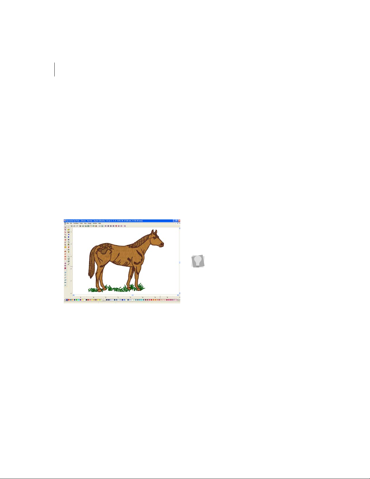
Opening designs
using the Library
feature
Xpressive allows you to open designs using
the Library feature. With the Library feature
you can organize your designs into
categories such as Sports, Animals,
Holidays, and so on.
To open designs with the Library
feature:
1 Do one of the following:
Choose Tools—Library.
From the Edit toolbar, click the Library
tool.
The Library window opens. In this window,
you can view the different design
categories and view the designs found in
each folder.
Page 37

2 To open a design, click on a design and
then click Open Design.
The cursor turns into a box with a cross
hair.
3 Click to place the design in the Xpressive
design workspace.
ELNA XPRESSIVE II 35
User’s Guide
Saving designs
You can use Save or Save As to save
designs in a variety of file formats such as the
Xpressive Unified File (*.ESX), Xpressive
Stitch File (*.EMD), Tajima Stitch Files
(*.DST) etc.
The Save As command lets you save an
alternative version of the design with a
different name, location, or file format. Save
As is handy when you want to keep your
original design and create another design
with slight modifications. The Save command
saves the changes you make to the current
design.
As a general rule, you should perform all
outline edits to a design first (in outline mode)
and save the design file. Next, you should
perform all stitch edits to the same design (in
stitch mode) and save the design file with a
different file name. If you follow this general
rule, you can avoid possibly losing your stitch
edits while doing significant design editing.
The design is placed on your workspace.
For more information on the general
rules of editing segments, see "Editing
Segments".
Page 38

36
To save a design:
1 Choose File—Save As.
You see the Save As dialog box.
2 In the Save in list, browse to the location
you want to save your file. You can save
design files to your hard drive, a disk, or
CD-ROM.
3 In the File Name box, enter the file name
for the design you want to be saved.
4 In the Save As type list, select the file
type you want the design to be saved as,
such as the Xpressive Unified File
(*.ESX).
5 Click Save.
To save changes to the current design:
• Choose File—Save.
Saving a Copy of a
Design
Xpressive allows you to easily save a copy of
designs using the Save As Copy command
from the File menu. You can save an
alternative version of any design with a
different name, location, or file format. This
command, however, differs slightly from the
Save As command.
When you save a design using Save As
Copy, the saved design file has no
connection to the open design. Any
subsequent saves made to a design using
the Save command from the File menu will
not be saved on top of the saved copy. This
feature is useful if you are creating many
variations of a design.
To save a copy of a design:
1 Choose File—Save As Copy.
You see the Save As dialog box.
2 In the Save in list, browse to the location
you want to save a copy of your file. You
can save design files to your hard drive, a
disk, or CD-ROM.
3 In the File Name box, enter the file name
for the design you want to be saved.
4 In the Save As type list, select the file
type you want the design to be saved as,
such as the Xpressive Unified File
(*.ESX).
5 Click Save.
Setting up design
worksheets
You can create helpful worksheets for your
designs including various settings such as
company name, design name, estimated
cost, and thread sequence. Y ou can also print
your customer’s name and other special
design commands. In addition, you now can
set the font and font size you want for your
design worksheet. You can also print
barcodes; however, you must first purchase
the barcode font.
You can also change the worksheet
settings before you print by clicking Print
Settings in the Print dialog box.
Page 39

ELNA XPRESSIVE II 37
User’s Guide
To set up worksheets for designs:
1 Choose Tools—Configuration—User
Settings.
You see the Settings property pages.
2 Click the Print Setting property page.
3 In the Print design as area, select one of
the following settings:
Outlines. Select to print the design
image with only outlines.
Stitches. Select to print the design
image with only stitches.
4 In the Image Setting area, select one or
more of the following settings:
Print actual size, or Scale Design or
Fit to Page. Select one of these
settings control how you view the
design in the worksheet. If you want to
scale the design, enter a percentage
value in the Scale Design box and the
design will be scaled to the specified
value when printed.
Simplify. Select this setting to print a
basic thread sequence view that
includes a simplified view of the colors
used and the color sequence rather
than the expanded thread sequence
that includes the name of the thread
color, thread number, thread chart
name, length of thread used, and the
number of stitches in the segment.
You must also have Thread Sequence
selected under Worksheet Setting.
Hide Jumps.
Hide Crosshairs.
Print 3D to print the design in 3D.
Print Outline files as Stitch files to
print a Stitch file worksheet from an
Outline file.
Print Hoop to print the hoop along with
the design.
Extend Crosshairs to the entire
worksheet’s width and height.
Print Images to print design
background images along with the
design.
5 In the Worksheet setting area, select the
information you want to print on your
worksheet.
6 In the Font setting area, click Font.
Browse and choose a different font type
and size for your worksheet. Click OK.
The default font is Arial at 12pt.
7 Click the User Preferences property page.
8 In the Company Name box, enter your
company name so that it is printed on the
worksheet.
9 Click OK.
Using the scroll bars
Scroll bars are the bars located along the
bottom and right side of the screen used to
view parts of a design outside the current
viewing area.
To use the scroll bars:
There are three movements you can perform
with the scroll bars:
Click a scroll arrow, on either end of a
scroll bar, to move the current view in
the selected direction.
Click and drag the scroll box to view
any part of your design in any
direction.
Click the inside of the bar itself to
move the view by one length or width
of the window.
Page 40

38
See your Windows®2000/XP documentation
for more information.
Working with Thread
Charts
Changing the colors in
designs
Xpressive provides several thread
manufacturer charts you can use to add or
change the thread colors in your design. The
color palette on the left side of the screen is
the default set of thread colors or the colors
that are used in the active design.
If your design is not a Xpressive Unified
File (*.ESX), we recommend that you
save your design as a Xpressive Stitch
File (*.EMD). Some embroidery machine
formats do not include thread color
information. Saving your file as a *.EMD
allows you to recall the design with the
same colors in the future.
To change the colors in designs:
1 At the bottom left-hand corner of your
screen, right-click the color you want to
change.
2 Choose Thread Change from the shortcut
menu.
You see the Thread Chart Dialog appear.
3 In the Chart list, select the thread chart
you want to view.
4 To select a color from the color chart, do
one of the following:
In the Thread Chart Dialog box, use
the left and right navigation arrows to
browse through the colors in the color
chart and select the color you want to
use.
In the Color box, enter the name of
the color you want to use and click
Search.
In the Code box, enter the code of the
color you want to use and click
Search.
5 Click OK.
The new color replaces the existing color
in the design workspace.
Page 41

Adding custom thread
colors to a custom thread
chart
Using the Windows®2000/XP Color palette,
you can add new thread colors to a custom
thread chart. The available manufacturer’s
thread charts may not have all the colors you
want or the colors are not a close enough
match to your colors; therefore, you can
create your own using the Thread Chart.
To add custom colors to a custom
thread chart:
1 Click at the bottom right-hand corner
of the screen.
You see the Thread Chart Dialog box.
2 In the Chart list, select Custom.
3 Click Add Thread.
You see the Thread Property Page.
4 Click the black square to change the
thread color.
You see the Color dialog box.
5 Select a color from the palette.
6 Click Add to Custom Colors.
You see the color appear in the Custom
Colors squares.
7 Click OK.
You see the Thread Property Page.
8 In the Color box, enter a name for the
thread color.
9 In the Type box, enter the type of thread
for the color.
10 In the Thickness box, enter a value for the
thread thickness.
11 Click OK.
The new color is added to a custom
Thread chart.
ELNA XPRESSIVE II 39
User’s Guide
Adding standard thread
colors to a custom thread
chart
You can create custom color palettes for your
designs. For example, you may want to
combine colors found in various thread
manufacturers’ thread charts to achieve a
certain look or color combination for your
designs.
Y ou cannot add colo rs to the pre-inst alled
manufacturers thread charts.
To add standard thread colors to a
custom thread chart:
1 Click at the bottom right-hand corner
of the screen.
You see the Thread Chart Dialog box.
2 In the Chart list, select a chart.
You see a new set of thread colors.
3 Click the color you want to add to a
custom color palette.
4 Click Add Thread.
You see the Thread Property Page.
5 Click OK.
6 In the Chart list, select Custom.
You see the thread color chosen in a
custom palette.
7 Click OK.
8 Repeat the steps above to add other
colors to a custom palette.
Page 42

40
Choosing a thread chart
The Thread Database consists of two color
palettes. The palette on the right shows a full
set of thread colors based on a color chart
from a thread manufacturer. You can also
create a custom palette of thread colors for
your designs. The color palette on the left
side of the screen is the default set of thread
colors or the colors that are used in the
current design.
To choose a thread chart:
1 Click at the bottom right-hand corner of
the screen.
You see the Thread Chart dialog box.
2 In the Chart list, select a thread chart.
The thread chart you select remains active
until you select another thread chart.
Changing the thread chart
If you know that a certain brand of thread has
colors that suit your designs, you can change
the manufacturer.
Removing a thread color
from the custom thread
chart
You can quickly remove a thread color from
the custom thread chart.
To remove a thread color from the
custom thread chart:
1 On the design color palette, right-click the
thread you want to remove from the
custom thread chart.
You see a menu appear.
2 Choose Delete.
You see the thread removed from the
custom chart.
To change the thread chart:
1 Click at the bottom right-hand corner
of the screen.
You see the Thread Chart Dialog box.
2 In the Chart list, select another thread
chart.
The color chart changes to show the
colors the manufacturer provides.
3 Click OK.
The colors on the bottom of the screen
change to the thread chart you selected.
Removing all threads in
the custom thread chart
You can empty all threads in the custom
thread chart.
To remove a thread from the custom
thread chart:
1 On the design color palette, right-click the
thread you want to remove from the
custom thread chart.
You see a menu appear.
Page 43

2 Choose Clear.
You see a warning message appear. If you
want to empty the custom thread chart
database, click OK. All threads will be
removed from the custom chart.
Printing Designs
Changing a design’s print
settings
You can customize embroidery design’s print
settings. Xpressive allows you to adjust the
image and worksheet information displayed
in design printouts.
You can also change the worksheet
settings before you print by clicking Print
Settings in the Print dialog box.
To change a design’s print settings:
1 Choose Tools—Configuration—User
Settings.
You see the Settings property pages.
2 Click the Print Setting property page.
3 In the Print design as area, select one of
the following settings:
Outlines. Select to print the design
image with only outlines.
ELNA XPRESSIVE II 41
User’s Guide
Stitches. Select to print the design
image with only stitches.
4 In the Image Setting area, select one or
more of the following settings:
Print actual size, or Scale Design or
Fit to Page. Select one of these
settings control how you view the
design in the worksheet. If you want to
scale the design, enter a percentage
value in the Scale Design box and the
design will be scaled to the specified
value when printed.
Simplify. Select this setting to print a
basic thread sequence view that
includes a simplified view of the colors
used and the color sequence rather
than the expanded thread sequence
that includes the name of the thread
color, thread number, thread chart
name, length of thread used, and the
number of stitches in the segment.
You must also have Thread Sequence
selected under Worksheet Setting.
Hide Jumps.
Hide Crosshairs.
Print 3D to print the design in 3D.
Print Outline files as Stitch files to
print a Stitch file worksheet from an
Outline file.
Print Hoop to print the hoop along with
the design.
Extend Crosshairs to the entire
worksheet’s width and height.
Page 44

42
Print Images to print design
background images along with the
design.
The hoop must be displayed in the
design window.
5 In the Worksheet setting area, select the
information you want to pr int on yo ur
worksheet.
6 In the Font setting area, click Font.
Browse and choose a different font type
and size for your worksheet. Click OK.
The default font is Arial at 12pt.
7 Click OK.
Previewing a design
before printing
You can preview a worksheet on the screen
before sending it to the printer.
To preview a design:
1 Choose File—Print Preview.
2 To zoom in and out of the previewed
worksheet, do the following:
To zoom in on the worksheet, click
Zoom In and scroll to view specific
parts of the design.
To zoom out on the worksheet, click
Zoom Out and scroll to view specific
parts of the design.
3 To change the settings for the design
worksheet, click Settings.
4 Click OK.
5 To close print preview and return to the
design window, click Close.
Printing design
worksheets
You can print worksheets for design files.
When you print a worksheet for a design file,
the worksheet information depends on the
selected settings in the Print Setting property
page. You can choose to include the design’s
name, dimensions, stitch count, estimated
cost, and other available settings when
printing your worksheet.
To print a worksheet for your design:
1 Choose File—Print Preview to view the
worksheet before you print.
2 To change the settings for the design
worksheet or check the information that
will be printed on the worksheet, click
Settings.
3 Click OK.
4 Click Print.
Printing in 3D View
You can print your design in 3D View. By
printing a design in 3D, you can show your
customers a realistic view of the design,
before you show them a sewn sample.
To print in 3D View:
1 Choose Tools—Configuration—User
Settings.
2 Click the Print Setting property page.
3 Select Print 3D.
4 Click OK.
5 Choose File—Print.
Page 45

Inputting and
Outputting Designs
To input and output designs you will need a
Smart Media card and a Floppy Disk Adapter .
Please refer to the Smart Media Card
definition in the “Glossary” section for more
detailed information.
Before you use the adapter you will need
to install the software that comes with th e
adapter. Please see the adapter’s
documentation for more information.
When you have installed the adapter
software, you are ready to input and output
designs to the Smart Media card. You insert
the Smart Media card into the adapter so that
the card works like a regular floppy disk.
Inputting a design
Using the Smart Media command, you can
input designs from disk. You can then modify
the design if you want, and then output the
design to sew on the Elna embroidery
machine.
You can use Windows® standard
commands with the mouse as well as the
Shift and Ctrl keyboard functions. You
can also right-click to open a shortcut
menu.
To input a design:
1 Insert the disk that has the designs you
want to input into the appropriate drive.
2 Choose File—Smart Media—Input.
You see the Smart Media Input dialog.
ELNA XPRESSIVE II 43
User’s Guide
3 In the Drive list box, choose the Drive
location.
4 Click on the design you want to input . To
input more than one design, press the
Shift key.
5 To import a continuous hoop design, click
the Continous hoop check box.
6 Click OK.
The design is loaded into Xpressive.
Outputting a design
Using the Smart Media command, you can
output a design to disk then export the design
to the Smart Media cards that the Elna
embroidery machine uses to read the design.
Once a design is output to the Smart Media
card, you can then sew it on the Elna
embroidery machine.
Page 46

44
To output a design:
1 Insert the disk into the appropriate drive.
2 Choose File—Smart Media—Output.
You see the Smart Media Input dialog.
Creating Multiple Hoop Designs
To create multiple hoop designs:
1 Open a new design file or load an existing
design.
2 Load the multiple hoop using the View—
Display Hoop—Load command. You will
see a dialog to select the proper hoop.
3 Select Multiple Hoop.
Create or edit your design planning to
place the parts that will be stitched in
different parts of the hoop separately. The
thick green lines show you the area that
you can use to adjust your design.
You can export each part of the design as
a separate file onto the Smart Media disk.
4 To select and export each part, select
File—Smart Media—Output. Repeat this
step to export all the parts of your design.
Creating Continuous Hoop
Designs
3 In the Drive list box, choose the Drive
location.
4 Choose the tag page to which you want to
output the design.
5 Click OK.
The design is output to the tag page you
selected.
Continuous hoop designs use separate
memory space on the Smart Media card;
they do not conflict with normal or
multiple hoop designs.
To create continuous hoop designs:
1 Open a new outline file or load an existing
design.
2 Load the proper hoop using the View—
Display Hoop—Load command.
You will see a dialog to select the proper
hoop.
3 Select Continous Hoop.
Create or edit your design planning to
place the parts inside the hoop edges. The
Page 47

thick green lines show you the area that
you can use to adjust your design.
4 To export the design to the SmartMedia
disk use Files—Smart Media—Output.
Outputting a design to the
Elna embroidery machine
You can output designs directly to the Elna
embroidery machine using the Output to
Machine command. The Output to Machine
commands works like a printer where you cue
your designs and the machine signals for
your design when it is ready to sew.
To output a design to the Elna
embroidery machine:
1 Open the design you want to output.
2 Choose File—Output to Machine.
You see the Machine Link dialog.
3 Choose the serial port (COM1, COM2,
and so on) and the machinespeed.
The design is then sent to the Elna
embroidery machine.
4 Click Close.
ELNA XPRESSIVE II 45
User’s Guide
Page 48

46
Page 49

CHAPTER 4
Viewing and Measuring
Designs
Xpressive gives you the methods you need to view your designs
with accuracy. You can view your entire design on-screen or pan
to view only parts of your design not visible in the design
workspace. Changing the background color of your design
window and altering how you view segments is simple when
using the Xpressive viewing buttons. If you want to view the
location on a design where the embroidery machine performs
commands, such as trims or jumps, you can use various Show
Commands available.
You can use Xpressive’s measurement tools to customize your
design space. Working with guidelines to align text and
segments, changing ruler settings, and defining measurement
units for rulers are simple when using our software. Xpressive’s
measurement tools make editing and working with designs easier
and more efficient.
In this chapter:
• Learn how to use the fundamental viewing tools, buttons, and
commands.
• Learn how to add, move and remove guidelines.
• Find out how to change the ruler origin and define ruler units.
• Learn how to measure designs.
Page 50

48
Viewing Methods and
Tools
Magnifying and reducing
the view
Use Zoom to magnify or enlarge parts of your
design. Reducing a design lets you see more
of your design on-screen. With Zoom you can
either left-click to enlarge your design or
right-click to make your design smaller.
To use Zoom:
1 Choose View—Zoom.
The pointer becomes a magnifying glass
with a plus sign.
2 Left-click the design.
3 Do one of the following steps:
Right-click to make your design
smaller.
Left-click that area to zoom-in on a
specific area.
To increase the zoom, continue
clicking and dragging the flexible box.
By doing so, you can view a single
stitch.
In the View toolbar, click the Back to
1:1 tool to zoom back out.
To disable Zoom:
• In the Edit toolbar, click the Select
tool once you get to the level of
magnification you want.
Viewing designs
You can view designs in a variety of ways
using one of the options in the Multi View
Paradigm. The different views are Enhanced
Main View, Sequence View, and 3-D View.
You can have all views open in Xpressive at
the same time.
To zoom-in on a specific area:
1 Choose View—Zoom.
The pointer becomes a magnifying glass
with a plus sign.
2 Click and hold your left mouse button and
drag your mouse to form a flexible box
around the specific area you want to see
in detail.
3 Drag the mouse across the area you want
to zoom-in until it is inside the box.
4 Do one of the following steps:
You can also press 1 on your keyboard
to zoom back to the original design size.
Multi View Paradigm
Viewing a design in Enhanced Main
View:
• Open the design.
The design opens in Enhanced Main View.
Page 51

To view a design in 3D View:
1 Open the design.
2 Select View—3D View.
You see the 3D View’s Option dialog box.
3 Adjust the Display and Light Source
options appropriately.
See "Setting 3D View options" for more
information on setting Display and Light
Source options.
4 Click OK.
You see the design appear in 3D view.
ELNA XPRESSIVE II 49
User’s Guide
Viewing the actual size of
designs
Click the Back to 1:1 tool to have the
design appear within its true measurements
where 1 centimeter equals 1 cent imeter onscreen. The rulers change to match the
number of centimeters or inches that the
design measures. Back to 1:1 is useful when
you have used Zoom and want to go back
and view the design based on its
measurements.
You can also press 1 on your keyboard
to go back to the original design size.
To view 3D stitches in Enhanced Main
View:
1 Open the design.
2 Click the Show 3-D Stitches tool in
the active window.
3 Click the Show 3-D Stitches tool
again to remove 3D stitches.
Viewing a design in Sequence View:
1 Open the design.
2 Select View—Sequence View.
You will see the Sequence View dialog
appear.
3 Select one of the views available.
4 To hide artwork segments in the
Sequence View dialog and on your
design workspace, click Hide Artwork
.
To use the Back to 1:1 tool:
• In the View toolbar, click the Back to 1:1
tool to go back to the original design
size.
Viewing the whole design
on-screen
Fit to Window allows you to view your whole
design in the active window, as well as any
loaded images. For example, after using
Zoom to examine different parts of your
design, you may want to see the design as a
whole before you close it or send it to the
machine.
You can also press W on your keyboard
to view your whole design on-screen.
To use the Fit to Window tool:
• In the View toolbar, click the Fit to Window
tool to view your whole design on-
screen.
Page 52

50
Viewing a design
selection on-screen
The Fit Selection to Window command allows
you to fit the current segment selection to the
design window. You can use this command to
focus on a specific area of an embroidery
design.
You can also press K on your key b oa rd
to view your design selection on-screen.
To view a design selection on-screen:
1 Select one or more segments from the
design window.
For more information, see “Selecting
segments”.
2 Choose View—Fit Selection to Window.
The selected segments will fill the entire
design window.
Viewing parts of a design
not visible in the design
workspace
You can move to parts of your design that go
beyond the window’s borders.
To pan up:
• Use the key to move up.
To pan right:
• Use the key to move right.
Viewing Buttons
Changing the background
color of the current
window
Depending on the type of artwork you are
using or the type of design you are creating,
you may want to change the background
color of your window. For example, if you are
creating a design with light color threads, you
may want your background darker so that the
stitches are more visible on-screen. Use the
change background color button located at
the top of the design window to change the
background color.
To change the background color:
1 Click the Change Background Color
tool.
You see the Color palette.
2 Select the color you want for your
background.
3 Click OK.
The new color replaces the old color on
your design workspace.
To pan down:
• Use the key to move down.
To pan left:
• Use the key to move left.
Showing and hiding
outline segments
Xpressive allows you to show and hide
outline segments. You can use the Show
outlines tool to quickly show and hide
segments as well as segment outlines.
Page 53

ELNA XPRESSIVE II 51
User’s Guide
Showing and hiding segments
and segment outlines using
various ribbon tools
You can use ribbon tools to hide selected
segments, hide unselected segments and
show all hidden segments. The Show outlines
tool also allows you to show and hide
segment outlines in any emb roidery design.
To show segment outlines:
• Click the Show outlines tool, if not
already selected.
You will see the segment outlines in your
design.
To hide segment outlines:
• Click the Show outlines tool again.
Showing and hiding
machine commands
Use Show Commands to view the locations
on the design where the embroidery machine
performs commands. These locations are
marked with different symbols to display the
command type.
This table shows you the symbol for each
command.
Command Symbol
Trim
Command Symbol
End
Start
Jump
Blank No symbol
No Command No symbol
Color Change
Changeover
To show commands:
• Click the Show Commands tool in the
window.
To hide commands:
• Click the Show Commands tool
again.
Showing and hiding the
stitch placements in
designs
Use the Show Dots tool to see the anchor
points and stitch penetration points in the
design window. The blue squares in your
design represent the anchor points that
control the shape of the design. The black
dots in your design represent the point where
the embroidery machine needle will penetrate
the fabric.
Stop
Page 54

52
To show the stitch placements:
1 Click the Show Dots tool in the active
window.
You can also press P on your keyboard
to show and hide the stitch placements.
2 To select the type of dots you want
displayed in your design, do one or more
of the following:
To view anchor points, right-click the
Show Dots tool and select Outline
Dots from the menu, if not already
selected.
To view stitch penetration points,
righ t-cli ck the Sho w D ots tool and
select Stitch Dots from the menu, if
not already selected.
To hide the stitch placements:
• Click the Show Dots tool again.
To show the beads:
1 Click S on your keyboard to activate the
Select tool.
2 Select the design or the segment.
3 Click the Show Beads tool.
4 Right-click the Show Beads tool.
You see a shortcut menu listing the bead
types available.
5 Select the beads types you want to view
from the shortcut menu:
Start Beads
Stop Beads
Angle Line Beads
Corner Beads
The bead types you select for viewing are
indicated by a check mark.
6 To hide a bead type, remove the
checkmark beside it’s name.
To hide the beads:
Showing and hiding
beads
You can show or hide the beads in a design
window. Positioning beads al ong paths allows
you to change exit and entry points and the
angle of stitches. Depending on what you are
editing, you can view the beads specific to
the type of segment.
• Click the Show Beads tool again.
Showing and hiding
stitches in design files
If you are using the Show Stitches tool to
view stitches in the design window, you first
need to generate the stitches. By generating
and showing stitches, you can see what the
stitches look like in your design file.
Page 55

ELNA XPRESSIVE II 53
User’s Guide
To show stitches:
1 Select the segment.
2 Press G on your keyboard to Generate
Stitches.
3 Click the Show Stitches tool.
To show stitches in a segment or group:
1 Select the segment.
2 Press G on your keyboard to Generate
Stitches.
You can press SHIFT+G on your
keyboard to generate stitches for all the
segments in your design.
3 Choose View—Stitches in Outline
Window—Show Active Group.
4 Click the Show Stitches tool.
You can now view the stitches of the
active segment.
To hide stitches:
• Click the Show Stitches tool again to
view regular outlines.
Defining grid settings
The Grid Settings help you align and
measure artwork and design elements. You
can set the grid to measure in centimeters or
inches according to your preference. When
you are working on a design file, you can
display the grid by clicking the Show Grid tool
on your ribbon.
By default, every horizontal and vertical line
will be highlighted in the major grid. If you
want to have additional guide lines, you can
add more major grid lines as well as a minor
grid. You can increase the spacing values for
the minor grid; however, zero and negative
spacing values are not supported. The minor
grid can also have different horizontal and
vertical spacing values.
To make grid lines more visible on particular
backgrounds, you can now change the color
of the major and minor grids. You should
choose separate colors for each grid type.
Tips
• You can turn on Snap to Grid (Shift+3) to
make sure that segments are aligned
along the grid lines when you move them.
When you draw baselines for lettering or
paths for shapes, those paths and
baselines snap to increments that
correspond with the grid. Press Shift+3 on
your keyboard to turn off Snap to Grid.
• You can show and hide grid lines by
clicking the Show Grid tool.
To define grid settings:
1 Do one of the following:
Choose View—Grid Settings—Grid
Settings.
Right-click on the rulers at t he left or
bottom of the window.
You see the Grid Settings dialog.
2 In the Minor grid area, complete the
following:
In the Horizontal spacing box, enter
the measurements for horizontal
spacing in millimeters or inches.
In the Vertical spacing box, enter the
measurements for vertical spacing
millimeters or inches.
Page 56

54
In the Color list, select a predefined
color to use for the minor grid. If you
want to choose from a larger selection
of colors, click More Colors from the
color box.
3 In the Major grid area, complete the
following:
In the Horizontal lines box, enter how
often you want horizontal lines to be
highlighted in the major grid. For
example, if you enter 3 in the
horizontal lines box, every third
horizontal line will be highlighted in
the major grid.
In the Vertical lines box, enter how
often you want vertical lines to be
highlighted in the major grid. For
example, if you enter 5 in the vertical
lines box, every fifth vertical line will
be highlighted in the major grid.
In the Color list, select a predefined
color to use for the major grid. If you
want to choose from a larger selection
of colors, click More Colors from the
color box.
4 In the Grid style area, select one of the
three grid styles.
You can choose from solid lines, dashed
lines, or dotted lines.
5 Do the following optional steps:
Select Snap to Grid to cause objects
to fasten to the grid.
Select the Snap style. Select Corner
or Center.
6 Click OK.
Showing and hiding grids
You can show the grids or, if they are in the
way, you can hide them.
To show the grids:
• Click the Show Grid tool in the active
window or choose View—Grid Settings—
Show Grid.
To hide the grids:
• Click the Show Grid tool or choose
View—Grid Settings—Show Grid.
Showing and hiding 3D
stitches
Use the Show 3-D Stitches tool to
preview a realistic 3D view of your design.
To show 3D stitches:
• Click the Show 3-D Stitches tool in
the active window.
You can also press 3 on your keyboard
to show 3-D stitches.
To hide the 3D stitches:
• Click the Show 3-D Stitches tool
again in the active window.
Viewing the sewing order
of designs
You can view the sewing order of designs by
using the draw ribbon tools located on top of
the design workspace. The speed control
determines the speed at which the design is
Page 57

ELNA XPRESSIVE II 55
User’s Guide
drawn on the screen. You can slide the speed
control from left to right to vary the rate of
sewing.
To view the sewing order of a design and
adjust the drawing speed, use any of the
following sewing simulator settings from the
Draw Ribbon:
For more information on using Draw
Ribbon tools, see “Draw Ribbon Tools”.
Tools What is does
Play backward one stitch:
Move backward in the design
by one stitch.
Play forward one stitch:
Move forward in the design by
one stitch.
Play backward one color:
Move backward in the design
to the beginning of the
previous color or selected
command.
Play backward: Move
backward through the design.
Pause: Pause the design
while drawing.
Stop: Stop the design while
drawing.
Play forward: Move forward
through the design.
Play forward one color:
Move forward in the design to
the beginning of the next
color or selected command.
Speed Control: Slide the
speed control to vary the rate
of sewing.
Viewing Commands
Displaying a hoop while
designing
Viewing the hoop or frame on the screen lets
you ensure that your design fits properly
when you run it on the machine. Use Display
Hoop to load and display embroidery
machine hoop files. The hoop serves as a
guide to help size and position your design in
the design window. Xpressive comes with
many different Tajima pre-loaded hoop sizes.
You can also create your own hoops
using programs like CorelDRAW™ and
AutoCAD™. You can Load, Remove,
Hide, and Rotate 90° any hoop you l oad.
To load a hoop:
1 Choose View—Display Hoop—Load.
You see the Load Hoop file dialog box.
The hoop types are separated into
different folders.
2 Choose from Round and Square hoop
files for specific Tajima embroidery
machine models.
3 Double-click the folder you want.
4 Select the hoop type you want.
5 Click Open.
6 Xpressive loads the hoop.
You see the hoop appear in your design
window.
To remove a hoop:
• Choose View—Display Hoop—Remove.
The hoop is removed.
Page 58

56
To hide a hoop:
• Choose View—Display Hoop—Hide.
The hoop is temporarily hidden from view.
To bring the hoop back in view:
• Choose View—Display Hoop—Hide
again.
To rotate the hoop 90°:
• Choose View—Display Hoop—Rotate
90°.
Xpressive rotates the hoop at a 90° angle
for you.
Finding potential stitch
problems
You can see possible problems in your
design before you sew it out. You can set
various lengths for stitches. Any stitches
outside the set ranges are highlighted to warn
you of potential problems that co uld cause
thread breaks, needle breaks, and undesired
machine stops.
To view stitch problems:
• Choose View—Display Markers—
Highlight Stitch Exception.
To hide outlines:
• Do one of the following:
Choose View—Stitches in Outline
Window—Hide Outlines.
Press Shift+X on your keyboard.
Setting the 3D View
options
Images need a certain amount of light to
display properly in 3D View. You can adjust
the light source settings and display options.
In most cases, you can use the default
settings for 3D View.
To set Display options:
1 Open a design.
2 Select View—3D View.
You see the 3D View’s Option dialog box.
3 Adjust the following Display and Light
Source options.
4 In the Thread Width box, enter the
thread’s width.
5 In the Bitmap box, click Browse to select a
background.
In the Fabrics folder, you see a list of the
background files installed with Xpressive.
6 Select Show actual size to show the
design in 3D View at its actual size rather
than at the default size.
Hiding outlines in design
files
Xpressive allows you to hide the outlines in
your design window and focus on the stitches
in your design file. You can use the Hide
Outlines option to temporarily remove
outlines from your view.
To set the Light source options:
1 In the Horizontal Angle box, enter an
angle for the horizontal light source.
To visualize how the light source works,
Page 59

ELNA XPRESSIVE II 57
User’s Guide
imagine a person in the middle of a circle
lying down horizontally and light shining
down on him or her.
2 In the Vertical Angle box, enter an angle
for the vertical light source.
To visualize how the light source works,
imagine a person in the middle of a circle
standing up vertically and light shining
down on him or her.
3 In the Intensity box, enter the intensity
setting based on how intense you want
the light source to be.
Viewing a design by
thread color order
Viewing a design by thread color lets you
view the stitches in your design window one
color at a time, which is important for viewing
a design’s sewing sequence. The View by
Color command follows a design’s thread
color order. For example, if Thread 1 is red,
Thread 2 is blue, and Thread 3 is yellow,
when you select View by Color, all your red
stitches appear first, blue stitches second
and so on.
To view a design by thread color:
1 Click the tool on the ribbon.
2 From the draw ribbon, click the draw
ribbon mode setting tool.
You see the Draw Ribbon Setting dialog
appear.
3 In the Stop at area, select one or more
machine commands you want the Play
backward one color button and Play
forward one color button to pause at as
the design sews out. For example, you
can enable the design to pause its
drawing whenever it encounters a Trim. If
you do not select any commands, the
design will pause at all color changes
while drawing.
Aligning and
Measuring Designs
Adding guidelines
You can use guidelines to help you precisely
align text and segments in your embroidery
designs. Guidelines are straight horizontal or
vertical lines that you drag from the rulers
into your design. These guidelines are easy
to make and they are useful for setting
alignment lines across the length or width of
the design workspace.
To create a horizontal guideline:
1 Position the pointer inside the ruler at the
bottom of the window.
2 Hold down the left mouse button and drag
the guideline into the design window.
3 Release the mouse when the guideline is
in the position you want.
To create a vertical guideline:
1 Position the pointer inside the ruler at the
left side of the window.
2 Hold down the left mouse button and drag
the guideline into the design window.
3 Release the mouse when the guideline is
in the position you want.
Page 60

58
Moving guidelines
You can use ruler guidelines to help you
precisely align text and segments in your
embroidery designs. Guidelines are straight
horizontal or vertical lines that you drag from
the rulers into your design. These guidelines
are easy to make and they are useful for
setting alignment lines across the length or
width of the design workspace.
To move existing guidelines:
1 Position the pointer on the guideline you
want to move.
2 Press Ctrl+Shift on your keyboard while
clicking and dragging your pointer to the
appropriate area of your design
workspace.
3 Release the mouse bu tton when y ou
reach the desired position for your
guideline.
The guideline is placed.
Changing the ruler origin
The ruler origin is the point where the
horizontal and vertical axes meet at zero on
the rulers. When you change the ruler
setting, the new setting becomes the default
for any existing or new design you open.
Changing the origin is also useful for
realigning the grid to your design.
To change the ruler origin:
1 Move the pointer to the lower left corner
of the rulers, where the rulers intersect.
2 Click the intersection, hold down the
mouse button and drag the ruler to the
location you want to place the origin.
As you drag, a large cross hair appears so
you can place the cross hair exactly where
you want it.
3 Let go of your mouse when the center of
the cross hair is where you want the
origin (0 point) to appear.
Defining ruler units
Large numbered rulers indicate the
measurement unit, such as inches or
centimeters. The small ticks indicate the
increments of the units such as ¼ inch. When
you magnify or reduce the view, the
increments of the unit measure adjust to
reflect the changes. In addition, if you change
the grid settings, the rulers change to fit the
measurements you set. The default for the
ruler measurement is inc hes.
The rulers change to fit the
measurements you set in the next
window you open.
To set the ruler units:
1 Choose Tools—Configuration—User
Settings.
2 Click the User Preferences property page.
3 Select Metric or Imperial.
4 Click OK.
Page 61

Measuring designs
The Measure tool lets you measure the
distance between any two points in your
design workspace. When you measure from
one point to another, the distance is
displayed in the status line located at the
bottom of the window. The status line shows
the horizontal and vertical distances the
Measure tool travels from the x and y axes,
the angle measured, and the total distances.
All measurements except the angle are
calculated in the unit of measure you set
in the User Preferences.
To measure designs:
1 In the View toolbar, click the Measure
tool.
Your cursor changes to a measuring tape
when in the Design Workspace.
2 Click and drag your mouse until you are
finished measuring the item.
3 Let go of your mouse when you are
finished measuring.
4 Look in the status line at the bottom of
your screen for the measurement.
5 Right-click to stop the measuring tool.
ELNA XPRESSIVE II 59
User’s Guide
Page 62

60
Page 63

CHAPTER 5
Creating Lettering and Merging
Designs
You can create beautiful lettering within your designs using
various Xpressive tools. Generate unique embroidery text in an
array of shapes and sizes using our powerful Text tool, as well as
the vast selection of commercially available TrueType® fonts. You
can edit the shape, color, size, and spacing of your lettering.
Xpressive also allows you to merge lettering and add any stock
design with just a few clicks of your mouse.
In this chapter:
• Learn how to create embroidery and true type lettering.
• Learn how to use the Text, Line Angle and Circle tools as well
as how to insert color changes and kern your lettering.
• Learn how to merge designs with and without lettering.
Page 64

62
Creating Embroidery
and TrueType®
Lettering
Creating lettering using
the Text tool
You can create a variety of lettering by using
the Lettering tools. Text creates lettering that
fits any curve you draw.
Important
• Xpressive only displays text and
characters found within font files. If you
enter text containing letters or characters
not found in the selected font file, only the
text found in the font file will be displayed
in the design workspace.
To create lettering:
1 Choose File—New to create a new file.
For more information, see "Creating New
Designs".
You see a new design window.
To create a corner point or to begin
creating a straight line again, release
CTRL on your keyboard.
Curved points should be entered as a set
of 3 points that define the arc of the
curve.
5 Press ENTER on your keyboard to
complete the baseline.
You see the Enter Text dialog appear.
6 In the Enter Text box, enter your text .
7 Click OK.
The lettering appears in the design
workspace.
To change the properties for your
lettering using the Segment Settings
property pages, press Ctrl+E on your
keyboard and choose Properties from
the menu or double-click the segment. To
change any of the settings, click the
appropriate property page.
2 In the Lettering Toolbar, click the Text
tool.
3 To place a straight point, left-click the
design workspace.
4 To place a curved point, complete the
following:
While you left-click the design
workspace, press and hold CTRL on
your keyboard.
You will see a preview of the curve
before you place the next anchor point.
Creating horizontal
lettering
You can create a variety of lettering by using
the Lettering tools. Line Angle creates
horizontal lettering. You can justify the
lettering to fill the box that you draw.
Page 65

Important
• Xpressive only displays text and
characters found within font files. If you
enter text containing letters or characters
not found in the selected font file, only the
text found in the font file will be displayed
in the design workspace.
To create horizontal lettering:
1 Choose File—New to create a new file.
For more information, see "Creating New
Designs".
You see a new design window.
2 In the Lettering Toolbar, click the Line
Angle tool.
3 To form the base of your box (the text
length), left-click and drag your mouse to
the right. Do not let go of the mouse until
you have drawn the height of your box.
4 To form the height of your box (the text
height), move your mouse upwards.
When the box is the size you want, let go
of the mouse button.
5 Left-click the design workspace to enter
the text.
You see the Enter Text dialog appe ar.
6 Enter the text in the Enter Text box.
7 Click OK.
You see the lettering appear in the design
workspace.
To change the properties for your
lettering using the Segment Settings
property pages, press Ctrl+E on your
keyboard and choose Properties from
the menu or double-click the segment. To
change any of the settings, click the
appropriate property page.
ELNA XPRESSIVE II 63
ser’s Guide
U
Creating circle lettering
You can create a variety of lettering by using
the Lettering tools. Circle creates circular
lettering with upper and lower text.
To change the properties for your
embroidery lettering using the Segment
Settings property pages, press Ctrl+E on
your keyboard and choose Properties
from the menu or double-click the
segment. To change any of the settings,
click the appropriate property page.
To create circle lettering:
1 Choose File—New to create a new file.
For more information, see "Creating New
Designs".
You see a new design window.
2 In the Lettering Toolbar, click the Circle
tool.
3 Click and drag to form the base of your
circle.
Your cursor becomes a flexible circle with
a line in it. The flexible circle allows you to
make the circle any size you want, and the
line guides the direction of your lettering.
Page 66

64
To convert TrueType® lettering to Satin
If you want the upper portion of the
circle's lettering to be on the top, make
sure the line is facing upwards. Check
the status line for measurements.
4 Let go of your mouse button. Click and
drag your mouse again to form the height
of your lettering.
You see the Circle baseline text box.
5 In the Upper and Lower boxes, enter your
lettering.
6 Click OK.
You see the lettering appear in the design
workspace.
stitches:
1 Choose File—New to create a new file.
For more information, see "Creating New
Designs".
You see a new design window.
2 In the Lettering Toolbar, click one of the
Lettering tools: Text , Line Angle ,
or Circle .
3 Form the text baseline.
For more information, see specific
sections on how to create the Lettering
tool you want to use.
4 Complete the baseline.
The lettering appears in the design
workspace.
5 Click the Segment Settings tool on
the ribbon.
You see the Segment Settings property
pages.
7 You can alter the text by shifting the
beads at the base of each letter.
If you add or remove letters, the text will
be adjusted accordingly without altering
the height of the existing letters.
Converting TrueType®
lettering to Satin stitches
For a different look, try converting your
TrueType® lettering to Satin stitches.
You can also press Ctrl+E on your
keyboard and choose Properties from
the menu or double-click the segment to
display the Segment Settings property
pages.
Page 67

6 Click the Te xt property page.
7 In the Fill Type list, select Satin Path.
8 To change any other settings, click the
appropriate property page and make
necessary changes.
9 Click OK.
The lettering is converted to Satin stitches.
ELNA XPRESSIVE II 65
User’s Guide
To insert a color change:
1 Select the lettering segment.
2 Click the Segment Settings tool on
the ribbon.
You see the Segment Settings property
pages.
3 Click the Text property page.
4 In the Text box, enter the tilde (~) sign
between the letters.
For example, if you want to add a color
change between each letter in the name
Jane, you would enter: J~A~N~E.
5 Click OK.
You see the lettering altered accordingly.
The colors in your lettering will change
according to the color palette on the left
side of your screen.
Inserting color changes
You can insert color change codes between
two letters using the tilde (~) mark. You can
enter only one color change between each
letter.
Kerning the space
between letters
Kerning adjusts the space between two
adjacent letters, making text more visually
appealing and easier to read. You can kern
text segments visually by clicking and
dragging on the letter you want to adjust,
helping you create lettering that looks
balanced and evenly spaced. You can also
adjust the kerning by entering any number of
kerning marks in the Text box. One mark
represents 1/20th of the letter M’s width.
Page 68

66
To kern the space between letters
visually:
1 Create your lettering.
2 Select your lettering, if it is not already
selected.
3 Place your pointer over the kerning point
located at the base of the letter you want
to move.
The mouse changes to a small triangle.
4 Click the point and drag the letter.
The lettering changes accordingly.
To kern the space between groups of
letters visually:
1 Create your lettering.
2 Select your lettering, if it is not already
selected.
3 Place your pointer over the kerning point
located at the base of the letters you want
to move.
The mouse changes to a small triangle.
4 Press CTRL on your keyboard.
5 Click the point and drag the letters.
All the letters to the left of the selected
letters, including the selected letter, are
moved as a group. The spacing between
these letters remains unaltered.
The lettering changes accordingly.
Page 69

ELNA XPRESSIVE II 67
User’s Guide
To move letters closer together:
1 Create your lettering.
2 Select your lettering, if it is not already
selected.
3 Click the Segment Settings tool on
the ribbon.
You see the Segment Settings property
pages.
4 Click the Text property page.
5 In the Text box, enter the less than sign
(<) between the letters you want to kern.
For example, if you wanted to tighten the
space between the "K" and "e" in the
word Kerning, you would enter:
K<<<<erning.
6 Click OK.
You see the lettering altered accordingly.
To move letters farther apart:
1 Create your lettering.
2 Select your lettering, if it is not already
selected.
Normal and adjusted kerning
Modifying Text segments
With Visual Text Editing you can modify text
segments and the segment will automatically
make the changes as you type. You can
manipulate text in a way similar to word
processing programs.
When modifying text segments, you
should be careful of how other segments
will be affected. For more information on
the general rules of editing segments,
see "Editing Segments".
3 Click the Segment Settings tool on
the ribbon.
You see the Segment Settings property
pages.
4 Click the Text property page.
5 In the Text box, enter the more than sign
(>) between the letters you want to kern.
For example, if you wanted more space
between the "K" and "e" in the word
Kerning, you would enter: K>>>>erning.
6 Click OK.
You see the lettering altered accordingly.
To modify text segments visually:
1 In the Edit toolbar, click the Select
tool and select the existing text.
You will see the handles around the
selected text segment.
Page 70

68
2 Press Ctrl+E on your keyboard.
You will see a shortcut menu.
3 Choose Modify Text… from the menu.
You will see the Enter Text dialog. You edit
the text in this box.
4 In this case, try deleting the "R" from
Mary.
Drawing mode for
lettering
A drawing mode is a method of inputting
anchor points. The drawing mode chosen
depends on the shape you want to create.
When you create lettering with the Text tool,
the QuickDraw drawing mode lets you make
unique baselines for your lettering.
QuickDraw mode
QuickDraw mode gives you the flexibility and
control you need to toggle between entering
straight and curved points for lettering.
You now can place straight and curved points
in Xpressive. To place a straight point, leftclick the design works pace. To place a
curved point, right-click the design
workspace.
Curved points should be entered as a set
of 3 points that define the arc of the
curve.
5 Click OK.
You see the change you made.
Lettering created in QuickDraw mode
Page 71

ELNA XPRESSIVE II 69
ser’s Guide
U
Merging Designs
You can merge design files into an active
design window. Use the Merge Design
tool to bring in a design and add lettering
around it. You can also import and edit the
design.
When performing major design editing,
you should be careful of how other
segments will be affected. For more
information on the general rules of
editing segments, see "Editing
Segments".
Xpressive allows you to merge design files
using a variety of file formats such as the
Xpressive Unified File (*.ESX), Xpressive
Outline File (*.ESE), etc. You can merge
Stitch and Machine Format Files such as the
Xpressive Stitch File (*.EMD), Melco
Condensed Files (*.CND), or Barudan Stitch
Files (*.DSB) into the unified design window
too; however, you mu st cho ose how you want
to treat the stitches in the design being
merged.
When you merge a Stitch or Machine Format
File, the Merge Stitch File Options dialog
automatically appears and you can merge the
design file in three ways:
• Merge a stitch file. This is the
standard merging option.
• Merge as stitch segments. This
option allows you to convert the
stitches into a series of stitch
segments. During the merging
process, stitches get grouped together
where groups are separated by trims,
color changes, changeovers, and
stops. Each group is added to the
design as a stitch segment. The
stitches in stitch segments should be
identical to the stitch file.
Outline changes made to any part of
the design will not affect stitch
segments. You cannot perform any
outline editing on stitch segments
except to resize, reflect, rotate, and
change the color of these stitch
segments; however, major editing is
not advisable. With the exception of
the previously mentioned outline edits,
the stitches which are part of a stitch
segment can only be modified by
direct stitch editing. This helps keep
the stitches true to what was in the
stitch file. If you want to perform more
advanced outline edits on stit ch
segments, then you must selectively
perform a Stitch to Outline conversion
(STO) to the segments and convert
them to our more advanced segment
types. However, this will not gua rantee
the preservation of your stitches.
For more information on STO, see
"Converting stitches to outline
segments".
• Convert merged stitches to
outlines. This option performs a STO
on the Stitch file first and then merges
the resulting Outline segments.
Convert merged stitches to outlines is
ideal for major editing such as density
reduction or vertex editing.
Page 72

70
With the Merge Design Tool, you can
merge a design with fish underwater with
another design containing additional fish to
create a unique effect.
To merge designs:
1 Do one of the following steps:
Choose File—Open to open an
existing file.
For more information, see "Opening
and closing designs".
Choose File—New to create a new file
and create a design.
For more information, see "Creating
new designs".
2 In the Edit toolbar, click the Merge Design
tool.
You see the Merge Design File dialog.
3 Do one or more of the following steps:
In the File Name box, select the
design file that you want to merge with
the opened design file.
The default is a Xpressive Unified File
(*.ESX).
In the Files of type list, select a
design file type for the design you
want to merge with the opened
design file.
Select Icon preview to view a small
picture of the design’s Stitch file.
Select Information to view the
design’s name, stitch count, size, and
color.
Click Icons to view all the designs in
the Designs folder.
If you are opening stitch files, select
one of the following options from the
list:
Page 73

ELNA XPRESSIVE II 71
User’s Guide
Convert stitches to outlines
Open as stitch segments
4 Click Open.
5 Move the cursor to the design workspace.
The cursor turns into a box with a large
cross hair that contains the design.
Before you place the design, press CTRL
on your keyboard to insert a color
change at the beginning of the merged
design.
6 Left-click to place the design.
The merged design file will appear in the
design workspace.
7 Alter the merged and existing designs
accordingly.
See the sections on "Design Editing in
Stitch Mode" and "Design Editing in
Outline Mode".
Merging designs with
lettering
Merging a design file with lettering allows you
to create many unique designs using stock
designs, or existing designs with lettering.
You can create your lettering first and merge
a design, or vice-versa.
To merge a design with lettering:
1 Choose File—New to create a new file.
For more information, see "Creating New
Designs".
You see a new design window.
2 Create the lettering for your design.
3 In the Edit toolbar, click the Merge Design
tool.
You see the Merge Design File dialog box.
Page 74

72
Open as stitch segments
6 Click Open.
7 Move the cursor to the design workspace.
The cursor turns into a box with a cross
hair.
8 Left-click and place the box where you
want the design merged.
The merged design appears in the design
workspace.
4 Select the design file that you want to
merge.
The default is a Xpressive Unified File
(*.ESX).
Before you place the design, press CTRL
on your keyboard to insert a color
change at the beginning of the merged
design.
5 If you are opening stitch files, select one
of the following options from the list:
Convert stitches to outlines
9 Alter the merged and existing designs
accordingly.
See the sections on "Design Editing in
Stitch Mode" and "Design Editing in
Outline Mode".
Page 75

CHAPTER 6
Changing your Segment
Settings
Xpressive provides an easy and efficient way to help you change
the settings and properties of your design segments.
When you make major changes to the properties of segments,
you should be careful of how other segments will be affected.
For more information on the general rules of editing segments,
see "Editing Segments".
Page 76

74
In this chapter:
• Learn how to adjust the settings of a segment.
• Learn how to adjust Text properties.
• Learn how to adjust Satin and Run properties.
• Learn how to adjust Steil stitch properties.
• Learn how to adjust Complex Fill properties.
• Learn how to adjust Carved Fill and Programmed Fill
properties.
• Learn how to adjust Pull-Compensation and Underlay
properties.
• Learn how to adjust Appliqué settings and properties.
• Learn how to adjust Cross-Stitch properties.
• Learn how to adjust Machine Command properties.
Page 77

Changing the settings
of a segment
In a design window, you can change the
segment settings. For exam ple, you c an
adjust the pull-compensation of the segment.
To open the Segment Setting property
pages, select the segment and click the
Segment Settings tool on the ribbon
or press Ctrl+E on your keyboard and
choose Properties from the menu.
To change the settings of a segment:
1 Open the design.
2 Select View—Sequence View.
You will see the Sequence View dialog
appear.
3 In the Sequence View box, browse to find
the segment you want to change.
4 Double-click the segment you want to
change.
You see the Segment Settings property
pages.
5 Make the necessary adjustments to the
settings.
6 Click OK.
ELNA XPRESSIVE II 75
User’s Guide
Embroidery Fonts
To choose an embroidery font:
1 Create your lettering or select an existing
lettering segment.
2 Press Ctrl+E on your keyboard and
choose Properties from the menu.
You see the Segment Settings property
pages.
To open the Segment Setting property
pages, you can also select the segment
and click the Segment Settings tool
on the ribbon or double-click the
segment.
Changing Text
properties
Choosing an embroidery
font
You can choose from a variety of embroidery
fonts. These fonts were digitized specifically
for the embroidery industry and are installed
in the C:\Program Files\Xpressive\Fonts
folder.
3 Click the Text property page.
4 Under Font Type, select Embroidery
Fonts.
5 In the Font list, select an embroidery font.
6 Click OK.
You see the lettering altered accordingly.
Page 78

76
Choosing a TrueType®
font
When you install Xpressive, the software
locates all the TrueType® fonts you have
installed on your computer.
TrueType® fonts are installed by the
operating system not by Xpressive.
3 Click the Text property page.
4 Under Font Type, select TrueType® Font.
5 In the Font list, select a font.
6 Click OK.
To open the Segment Setting property
pages, you can also select the segment
and click the Segment Settings tool
on the ribbon or double-click the
segment.
You see the lettering altered accordingly.
Choosing the Fill type for
TrueType® lettering
You can choose different Fills for TrueTy pe®
lettering using the Fill Type setting on the
Text property page.
TrueType® fonts
To choose a TrueType® font:
1 Select the lettering segment.
2 Press Ctrl+E on your keyboard and
choose Properties from the menu.
You see the Segment Settings property
pages.
To choose the Fill type:
1 Select the lettering segment.
2 Click the Segment Settings tool on the
ribbon.
You see the Segment Settings property
pages.
3 Click the Text property page.
4 In the Fill Type list, select the Fill type.
5 Click OK.
Changing the shape of
lettering manually
Xpressive allows you to change the shape of
text by resizing and skewing characters.
Page 79

You can easily edit individual characters in
lettering. You no longer have to convert
lettering into segments in order to perform
character edits.
You can open and work with lettering
segments saved in older design file
formats. To save character edits made in
the latest version of Xpressive, you must
save the design file in *.ESX format.
To resize lettering manually:
1 Create your lettering.
2 Select the center bead of the character
you want to edit.
You see an editing box appear around the
selected character.
To Do this
Resize the width of a
character
Resize the height of a
character
At the right side of the
editing box, drag the
middle squared bead.
At the top of the editing
box, drag the middle
squared bead.
ELNA XPRESSIVE II 77
User’s Guide
3 You can now resize the selected
character in one of the following ways:
Resize the width and
height of a character
simultaneously
At the top of the editing
box, drag the right
squared bead.
4 To resize another character in the
lettering segment, select the center bead
of the character and use the editing box
to resize.
5 When you are finished resizing a
character, click its center bead again.
The editing box will disappear.
Page 80

78
At the top of the editing box, drag the
left squared bead to the left or right.
To skew lettering manually:
1 Create your lettering.
2 Select the center bead of the character
you want to edit.
You see an editing box appear around the
selected character.
3 To skew a character left or right, do the
following:
Character skewed
left
4 To skew another character in the lettering
segment, select the center bead of the
character and use the editing box to
skew.
5 When you are finished skewing a
character, click its center bead again.
The editing box will disappear.
Character skewed
right
Changing the vertical
position of lettering
You can easily change the vertical position of
lettering segments with Xpressive. When you
manually move the vertical position of
individual characters, the original shape of
the character will remain the same.
You can open and work with lettering
segments saved in older design file
formats. To save character edits made in
the latest version of Xpressive, you must
save the design file in *.ESX format.
Page 81

To change the vertical position of
lettering:
1 Create your lettering.
2 Select the center bead of the character
you want to edit.
You see an editing box appear around the
selected character.
ELNA XPRESSIVE II 79
User’s Guid
4 To change the position of another
character in the lettering segment, select
the center bead of the character and
change the vertical position accordingly.
5 When you are finished changing the
vertical position of a character, click its
center bead again.
The editing box will disappear.
e
3 To change the vertical position of the
character, click and drag the center bead
up and down.
Changing the size and
position of circle lettering
You can control the height and position of
circle lettering with Xpressive.
T o change the size and position of circle
lettering:
1 Select the circle lettering.
Page 82

80
Do this Get this
Change the height of
the lettering and not
affect the upper
At the top of the upper
baseline, drag the
white square bead.
baseline.
2 Do one or more of the following to change
the size and position of the lettering:
Do this Get this
Change the height of
the lettering and not
affect the lower
At the top of the lower
baseline, drag the
white square bead.
baseline.
Change the position
and size of the upper
baseline.
Click and drag the top
overlapping square
bead at the center.
Page 83

Do this Get this
Change the position
and size of the lower
baseline.
Click and drag the
second overlapping
square bead at the
center.
Rotating lettering
manually
Xpressive allows you to easily rotate
characters in lettering segments. You no
longer have to convert lettering into
segments in order to perform character edits.
You can open and work with lettering
segments saved in older design file
formats. To save character edits made in
the latest version of Xpressive, you must
save the design file in *.ESX format.
To rotate lettering manually:
1 Create your lettering.
2 Select the center bead of the character
you want to edit.
You see an editing box appear around the
selected character.
ELNA XPRESSIVE II 81
User’s Guide
3 To rotate a character, do the following:
At the line above the editing box, drag
the round bead to the left or right.
4 To rotate another character in the lettering
segment, select the center bead of the
character and use the editing box to
rotate.
5 When you are finished rotating a
character, click its center bead again.
The editing box will disappear.
Page 84

82
Changing the shape of
lettering
You can change the shape of text using
envelopes.
Envelope examples
T o choose an envelope:
1 Select the lettering segment.
2 Press Ctrl+E on your keyboard and
choose Properties from the menu.
You see the Segment Settings property
pages.
3 Click the Text property page.
4 In the Envelope list, select a shape.
5 Click OK.
You see the lettering altered accordingly.
Setting the lettering
height
Use the Height setting to set the height you
want for your embroidery lettering. You can
override this height when drawing the box for
the text or by dragging the handles.
Lettering at different heights
To set the lettering height:
1 Select the lettering segment.
2 Press Ctrl+E on your keyboard and
choose Properties from the menu.
You see the Segment Settings property
pages.
3 Click the Text property page.
4 In the Height box, enter the height you
want for your lettering.
5 Click OK.
You see the lettering altered accordingly.
Setting the justification
You can change the justification for your
lettering.
Page 85

To change the justification:
1 Select the lettering segment.
2 Press Ctrl+E on your keyboard and
choose Properties from the menu.
You see the Segment Settings property
pages.
3 Click the Text property page.
4 In the Justify list, select one of the
following justification types:
5 Click OK.
You see the lettering altered accordingly.
Setting lock stitches for
lettering
You can add lock stitches to your lettering. A
lock stitch keeps your stitches from pulling
apart by firmly attaching the thread at the
location before a long stitch or a trim.
However, if a trim is placed between two
letters then a lock stitch is inserted before the
trim.
ELNA XPRESSIVE II 83
User’s Guide
Zoomed-in view of a standard lock stitch.
To set a lock stitch:
1 Select the lettering segment.
2 Press Ctrl+E on your keyboard and
choose Properties from the menu.
You see the Segment Settings property
pages.
3 Click the Commands property page.
4 In the Lock stitch-End list, select a lock
type:
Select None to place a lock stitch at
the end of the text segment only.
Select Basic to place a lock stitch
after each letter in the text segment.
5 Click OK.
You see the lettering altered accordingly.
Page 86

84
Changing Satin
properties
Selecting a Fill pattern for
Satin stitches
You can select a pattern for Satin stitches on
the Satin property page. You can choose
from any of the standard Fill patterns that are
installed with Xpressive. Embroidery text
lettering uses Satin stitches.
To change the properties for your
embroidery lettering using the Segment
Settings property pages, you can use
one of three methods after selecting the
segment. You can click the Segment
Settings tool on the ribbon, press
Ctrl+E on your keyboard and choose
Properties from the menu or double-click
the segment. To change any of the
settings, click the appropriate property
page.
In the Carved Tile Pattern list, select
the Carved Tile pattern you want to
use.
7 Click OK.
You see the lettering altered accordingly.
Setting the density for
Satin stitches
You adjust density according to the design’s
size and the fabric you are using. Lighter
fabrics and smaller designs require less
density.
To select a pattern for satin stitches:
1 Create your lettering, select an existing
lettering or Satin segment.
2 Press Ctrl+E on your keyboard and
choose Properties from the menu.
You see the Segment Settings property
pages.
3 Click the Satin property page.
4 In the Fill Pattern Type list, select the
Standard or Carved Tile pattern type.
5 If you selected a Standard Pattern type,
complete the following:
In the Standard Pattern list, select the
Standard pattern you want to use.
6 If you selected a Carved Tile Pattern type,
complete the following:
Various densities—tight density to loose density
Page 87

ELNA XPRESSIVE II 85
ser’s Guide
U
To set the density:
1 Select the Satin segment.
2 Click the Segment Settings
ribbon.
You see the Segment Settings property
pages.
3 Click the Satin property page.
4 In the Density box (-/+) area, use the
density slider to specify the density
level for your Satin stitches.
To create stitches with a looser density,
move the density slider to the left. To
create stitches with a tighter density,
move the density slider to the right.
In the Segment Settings dialog, look at
the image beside the density slider. As
you adjust the density level of your
segment and move the density slider to
the left or right, you can see how the
stitches in your design will be affected.
5 Click OK.
You see the lettering altered accordingly.
tool on the
Changing Satin Effect
properties
Applying a jagged effect
to Satin stitches
You can apply jagged edges to your stitches.
You need to choose a minimum and
maximum setting for the jagged edge. The
range can be a positive or a negative value. If
you set a negative value, the jagged edge is
placed on the inside of the column. If you set
a positive value, the jagged edge is placed on
the outside of the column.
Jagged effects Jagged range
To apply a jagged effect:
1 Select the Satin Path segment.
2 Click the Segment Settings
ribbon.
You see the Segment Settings property
pages.
3 Click the Satin Path/Column Effects
property page.
4 In the Jagged list, select one of the
following jagged effect types:
None.
Both to make both sides of the
stitches jagged.
First to make the first side of the
stitches jagged.
Second to make the second side of
the stitches jagged.
5 In the Min. Jagged Range area, use th e
jagged range slider to specify the
minimum jagged range for your Satin
Path stitches.
To place the jagged edge on the inside of
the column (positive value), mo ve t he
jagged range slider to the left. To place
tool on the
Page 88

86
the jagged edge on the outside of the
column (negative value), move th e
jagged range slider to the right.
In the Segment Settings dialog, look at
the image beside the jagged range
sliders. As you adjust the minimum and
maximum jagged ranges for your
segment and move the jagged range
sliders to the left or right, you can see
how the stitches in your design will be
affected.
6 In the Max. Jagged Range area, use t he
jagged range slider to specify the
maximum jagged range for your Satin
Path stitches.
To place the jagged edge on the inside of
the column (positiv e value), m o ve t h e
jagged range slider to the left. To place
the jagged edge on the outside of the
column (negative value), move th e
jagged range slider to the right.
7 Click OK.
You will see your segment altered
accordingly.
Changing Run
properties
To choose a style:
1 Select the Run segment.
2 Click the Segment Settings
ribbon.
You see the Segment Settings property
pages.
3 Click the Run property page.
4 In the Run Style list, select one of the
following styles:
Run. For more information, see
"Common Embroidery stitch types".
Two-ply. For more information, see
"Common Embroidery stitch types".
Bean. For more information, see
"Common Embroidery stitch types".
Programmed. For more information,
see “Using Programmed Runs.”
5 Click OK.
You will see your segment altered
accordingly.
tool on the
Setting the stitch length
for Run stitches
You can control the length for the Run
stitches using the Stitch Length setting. You
set the stitch length in the Run property page.
Choosing a style for Run
stitches
You can choose a style for Run stitches to
create unique stitch effects for detailing or
borders.
Page 89

ELNA XPRESSIVE II 87
User’s Guide
To change the stitch length:
1 Select the Run segment.
2 Click the Segment Settings
the ribbon.
You see the Segment Settings property
pages.
3 Click the Run property page.
4 In the Stitch Length box, enter the stitch
length.
5 Click OK.
tool on
Changing Steil
properties
Setting the width for Steil
stitches
You can set the width of Steil stitches.
To set the width for Steil stitches:
1 Select the Steil segment.
Changing Complex
Fills properties
Adjusting the stitch
length for the selected Fill
pattern
You can adjust the stitch length for Fill
patterns on the Satin or Fills property pages.
To adjust the stitch length:
1 Select the Complex Fill segment.
2 Click the Segment Settings
the ribbon.
You see the Segment Settings property
pages.
3 Click the Satin or Fills property page.
4 In the Stitch Length box, enter the stitch
length.
5 Click OK.
tool on
2 Click the Segment Settings
the ribbon.
You see the Segment Settings property
pages.
3 Click the Steil property page.
4 In the Steil Width box, enter the width.
5 Click OK.
You will see your segment altered
accordingly.
tool on
Selecting a pattern for
Fills
When you work with TrueType® fonts and the
Complex Fill tool, you can select a
pattern for Fills from the Complex Fills
property page. You can choose from any of
the Fill patterns that are installed with
Xpressive.
When you work with embroidery fonts
and Satin tools, you select a pattern fr om
the Satin property page.
Page 90

88
Setting the stitch density
for Fills
You adjust density according to the design’s
size and the fabric you use. Generally
speaking, lighter fabrics and smaller designs
require less density. You can set the density
in the Complex Fills property page.
Fill pattern
To select a pattern:
1 Create your lettering, select an existing
lettering or Complex Fill segment.
2 Click the Segment Settings
the ribbon.
You see the Segment Settings property
pages.
3 Click the Complex Fills property page.
4 In the Fill Pattern Type list, select the
Standard or Carved Tile pattern type.
5 If you selected a Standard Pattern type,
complete the following:
In the Standard Pattern list, select the
Standard pattern you want to use.
6 If you selected a Carved Tile pattern type,
complete the following:
In the Carved Tile list, select the
Carved Tile pattern you want to use.
7 Click OK.
You will see your segment altered
accordingly.
tool on
Fill pattern with various density measurements.
To set the stitch density:
1 Select the Complex Fill segment.
2 Click the Segment Settings
the ribbon.
You see the Segment Settings property
pages.
3 Click the Complex Fills property page.
4 In the Density box (-/+) area, use the
density slider to specify the density level
for your Satin stitches.
To create stitches with a looser density,
move the density slider to the left. To
create stitches with a tighter density,
move the density slider to the right.
In the Segment Settings dialog, look at
the image beside the density slider. As
you adjust the density level of your
segment and move the density slider to
the left or right, you can see how the
stitches in your design will be affected.
tool on
5 Click OK.
Page 91

ELNA XPRESSIVE II 89
User’s Guide
Changing Carved Fill
properties
Choosing a Carved Tile
pattern
When you install Xpressive, Carved Tile
patterns are installed on your computer. You
can select a Carved Tile pattern from the
Carved Tile Pattern property page. Carved
Tile patterns create a grooved or chiseled
effect for the designs that you create.
To choose a Carved Tile pattern:
1 Select the Carved Tile segment.
2 Click the Segment Settings
the ribbon.
You see the Segment Settings property
pages.
3 Click the Satin or Complex Fills property
page.
4 In the Carved Tile Pattern list, select a
pattern.
5 Click OK.
You will see your carved tile segment
altered accordingly.
tool on
To create Carved Fills:
1 In the Punching toolbar, click the Complex
Fill tool.
2 Click the Segment Settings
the ribbon.
You see the Segment Settings property
pages.
3 Click the Satin or Complex Fills property
page.
4 In the Fill Pattern Type list, select Carved
Tile.
5 In the Carved Tile Pattern list, select a
Carved Tile pattern.
In this case, we have chosen pattern 212.
6 Click OK.
7 Punch the segment in the design
workspace.
8 Click the Auto Close tool on the
ribbon or press
close the segment.
9 Press ENTER on your keyboard.
Your cursor turns into a green arrow. You
now need to set the entry and exit points
and the angle line.
H on your keyboard to
tool on
Creating Carved Fills
To create a Carved Fill, you need to create a
segment with the Complex Fill tool. A
variety of patterns are installed with
Xpressive and you can also create custom
Carved Fill patterns. Carved Fill segments
are often used as background Fills.
Page 92

90
Now, you need to change the properties of
10 To set the start and stop points and the
angle line for your segment, do the
your segment to match the fabric and
thread you will be using.
following steps:
When the pointer becomes a green
arrow, click where you want to set the
start point.
You will see a green bead where you
Once you close the segment, you can
right-click repeatedly to quickly set the
default start and stop points and ang le
line.
clicked and the pointer becomes a red
arrow.
When the pointer becomes a red
arrow, click where you want to set the
stop point.
You will see a red triangle bead where
you clicked and the pointer becomes a
small arrow with a bead.
When the pointer becomes a small
arrow with a bead, click and drag from
11 Click the Segment Settings tool on
the ribbon.
You see the Segment Settings property
pages.
12 Click the appropriate property page and
make the setting changes.
Important settings include Pull
Compensation and Underlay.
the left of the segment to right of the
segment to place an angle line in your
segment.
Page 93

Changing
Programmed Fill
properties
Adjusting the stitch
length for Programmed
Fill patterns
When you create Programmed Fill patterns
you may need to adjust their stitch length.
You can adjust the stitch length in the Stitch
Length text box in the Programmed Fill
property page. Adjusting the stitch length can
help control the pattern’s size.
To adjust the stitch length of
Programmed Fills:
1 Select the Programmed Fill segment.
ELNA XPRESSIVE II 91
User’s Guide
Stitch Length set to
50 pts
Stitch Length set to
70 pts
Choosing a Programmed
Fill pattern
When you install Xpressive, Programmed Fill
patterns are installed on your computer. You
can select a Programmed Fill pattern from
the Programmed Fill Patt ern box in the
Complex Fills property page.
2 Click the Segment Settings
the ribbon.
You see the Segment Settings property
pages.
3 Click the Complex Fills property page.
4 In the Stitch Length text box, enter the
stitch length
5 Click OK.
You will see your segment altered
accordingly.
tool on
To choose a Programmed Fill pattern:
1 Select the Programmed Fill segment.
2 Click the Segment Settings
the ribbon.
You see the Segment Settings property
pages.
3 Click the Complex Fills property page.
4 In the Programmed Fill Pattern list, select
a pattern.
5 Click OK.
You will see your segment altered
accordingly.
tool on
Page 94

92
Changing Pull
Compensation
properties
Adjusting pullcompensation
You can adjust the pull-compensation in your
design. You use the settings in the Pull Comp
property page to adjust the pullcompensation.
None and Percentage pull-compensation
To adjust the pull-compensation:
1 Select the Satin segment.
2 Click the Segment Settings
the ribbon.
You see the Segment Settings property
pages.
3 Click the Pull Comp property page.
4 Select one of the following options:
None. Makes no adjustments to pull-
compensation.
Percentage. Move the Value slider to
specify the amount of pullcompensation you want your segment
to have and, if necessary, enter the
tool on
maximum value of pull-compensation
in the Maximum range box.
In the Segment Settings dialog, look at
the image beside the V alue sl ider . As you
adjust the amount of pull-compensation
for your segment and move the value
slider to the left or right, you can s ee how
the stitches in your design will be
affected.
5 Click OK.
You see the segment altered accordingly.
Changing Underlay
properties
Selecting the underlay
type
You can select underlay types for various
types of stitches. Choose from Contour and
Perpendicular.
You can combine underlay types to get
maximum coverage.
Page 95

ELNA XPRESSIVE II 93
User’s Guide
To select an underlay type:
1 Select the segment.
2 Click the Segment Settings
the ribbon.
You see the Segment Settings property
pages.
3 Click the Underlay property page.
4 In the Type area, select the underlay type
you want: Contour or Perpendicular.
5 Adjust any of the other settings. Refer to
the related procedures for more
information.
6 Click OK.
tool on
Changing the inset
distance
Y ou can change the inset dist ance. Xpressive
calculates the inset distance (the dista nce the
underlay stitches are placed from the edge of
the top stitching.) Inset distance changes the
amount of underlay coverage. The smaller
the inset distance, the more coverage you
have.
To change the inset distance:
1 Select the segment.
2 Click the Segment Settings
the ribbon.
You see the Segment Settings property
pages.
3 Click the Underlay property page.
4 In the Type area, select the underlay type:
Contour or Perpendicular.
You can combine underlay types to get
maximum coverage.
5 In the Inset Distance box, enter the
amount of distance you want.
Enter a zero value if you want to place the
underlay directly on the edge of the
segment. The default is 0.6 mm.
6 Click OK.
tool on
Increasing the number of
lines for perpendicular
underlay
When you select perpendicular underlay, you
can set the inset distance and increase the
number of perpendicular lines.
Inset
distance 0.60
mm
Inset
distance
0.120 mm
Inset
distance
0.180
To increase the number of lines:
1 Select the segment.
2 Click the Segment Settings
the ribbon.
You see the Segment Settings property
pages.
3 Click the Underlay property page.
4 In the Type area, select Perpendicular.
5 In the Number of Lines box, enter the
number of perpendicular lines you want.
6 Click OK.
tool on
Page 96

94
Specifying the underlay
density
You can specify the density for underlay
stitches. Just like density for your top
stitches, underlay density is measured in
embroidery points (pts) and stitches per inch
(spi). In embroidery points, you measure the
distance between stitches. In stitches per
inch, you determine the number of stitches
per inch.
To set the underlay density:
1 Select the segment.
2 Click the Segment Settings
the ribbon.
You see the Segment Settings property
pages.
3 Click the Underlay property page.
4 In the Type area, select one of the
following underlay types:
Contour
Perpendicular
tool on
To specify the underlay stitch length:
1 Select the segment.
2 Click the Segment Settings
the ribbon.
You see the Segment Settings property
pages.
3 Click the Underlay property page.
4 In the Type area, select one of the
following underlay types:
Contour
Perpendicular
You can combine underlay types to get
maximum coverage.
5 In the Stitch Length box, enter the stitch
length that you want for your underlay
stitches.
The default is 25.0 pts.
6 Click OK.
tool on
Changing Commands
You can combine underlay types to get
maximum coverage.
5 In the Density (+/-) box, enter the density
value in pts.
The default is 20.0 pts.
6 Click OK.
Specifying the underlay
stitch length
You can specify the stitch length for your
underlay stitches. You can increase or
decrease the length according to your
underlay needs.
properties
Adding machine
commands
You can add specific machine commands to
your design such as stops, jumps, and
changeovers.
Page 97

ELNA XPRESSIVE II 95
User’s Guide
To add a machine command:
1 Select the segment.
2 Click the Segment Settings
the ribbon.
You see the Segment Settings property
pages.
3 Click the Commands property page.
4 In the Command list, select one of the
following commands:
• Select Trim to trim the thread.
• Select Stop to stop the machine.
• Select No Command to not add
commands.
5 Click OK.
tool on
Applying lock stitches
You can apply predefined and custom lock
stitches using the Commands property page.
You can apply lock stitches to the start and
end of segments. You can also spe cif y th e
length of start and end lock stitches or
create custom lock stitches.
The line (lock stitch type) adds 4 stit ches
in a straight line. Each stitch will match
the specified lock stitch length.
A zoomed-in view of a basic lock
stitch
To apply a lock stitch:
1 Select the segment.
2 Click the Segment Settings
the ribbon.
You see the Segment Settings property
pages.
3 Click the Commands property page.
4 In the Lock Stitch - End list, select the
type of end lock stitch you want applied to
your segment:
None
Basic
Line
5 Click OK.
tool on
Page 98

96
Changing a thread color
number
You can change the thread color of a design
by using the property pages rather than the
thread palette at the bottom of the Xpressive
workspace. The first color in the palette is
Thread 1, the second color in the palette is
Thread 2, and so on.
To change a thread color number:
1 Select the segment.
2 Click the Segment Settings
the ribbon.
You see the Segment Settings property
pages.
3 Click the Commands property page.
4 In the Thread list, select the thread
number.
5 Click OK.
You see the segment altered accordingly.
tool on
Page 99

CHAPTER 7
Design Editing in Stitch Mode
When you use the Stitch Select tool from the Stitch Edit
toolbar, Xpressive automatically chan ges to Stitch Mode. In Stitch
Mode, you can edit stitches in the unified design window.
Stitch-by-stitch editing is easy and you can edit designs in a
variety of ways. Use the Navigation bar to move through the
stitches of a design. Y ou can move stitch-by-stitch if you want and
then select and highlight the exact stitches for editing.
When performing major stitch editing, you should use caution.
For more information on the general rules of stitch editing, see
"Editing Stitches and Stitch Groups".
You can also edit groups of stitches. Moving portions of a design
is simple with the Lasso Stitch Select tool. You can save
valuable time by cutting and pasting stitch groups into other
designs. You can combine parts of several designs to create
something completely new.
In this chapter:
• Learn the different ways to move through the design window
and how to edit stitch and stitch groups.
• Find out how to group and ungroup stitches.
Page 100

98
Editing Stitches and
Stitch Groups
In Xpressive’s unified window, you can edit a
design’s stitches and stitch groups while in
stitch mode. When you use the Stitch Select
tool from the Stitch Edit toolbar,
Xpressive automatically changes to Stitch
Mode.
As a general rule, you should perform all
outline edits to a design first (in outline mode)
and save the design file. Next, you should
perform all stitch edits to the same design (in
stitch mode) and save the design file with a
different file name. If you follow this general
rule, you can avoid possibly losing your stitch
edits while doing significant design editing.
A segment’s stitch edits may be lost if you
perform an outline editing action that forces
Xpressive to regenerate stitches for the
segment. The following are design editing
actions that can force stitch regeneration in
your design:
• Resizing a segment.
• Modifying the settings for a segment.
• Moving a segment.
Typically, when you add or modify segments
in a design, Xpressive will not regenerate
stitches for the entire design. The software
will, however, generate stitches for the
segment being modified unless region
carving or line carving requires regeneration.
If region carving segments require
regeneration, segments affected by region
carving will be regenerated. If line carving
segments require regeneration, segments
affected by line carving will be regenerated.
Selecting stitches in
various ways
You can select stitches in a variety of ways.
The Stitch Select tool allows you to select
and modify individual or groups of stitches in
your designs. You select stitches by clicking
on a single stitch or by clicking and dragging
to draw a box around parts of the design.
With the Lasso Stitch Select tool, you
can draw a polygon to fit around parts of the
design instead of a box.
The spacebar is a hotkey that toggles
between stitch editing using the Stitch
Select tool and outline editing using
the Select tool. One of these tools
must be selected.
Remember to use caution while editing
stitches and segments. For more
information, see "Editing Stitches and
Stitches Groups".
T o select stitches using the S titch Select
tool:
1 In the Stitch Edit toolbar, click the Stitch
Select tool.
2 To select a single st itch, click the stitch
you want.
3 To select multiple stitches, do one of the
following:
Click and drag to form a rectangle box
around the stitches you want to select.
 Loading...