

Page 1
PART NAMES
AND
FUNCTIONS
SETTING UP STORING
OPERATION
PROCEDURE
VARIOUS
FUNCTIONS
AND
OPERATIONS
TROUBLE
SHOOTING
SPECIFICATIONS
English
Document Camera
INSTRUCTION
MANUAL
Please read this instruction manual carefully
before using this product and keep it for future
reference.
Page 2
2
English
Follow these guidelines to use the product safely.
These "IMPORTANT SAFEGUARDS" indicate important points that
should be followed to use this product safely and correctly and prevent
damage to the product or other property and injury to you and others.
Re ad care fully befo re oper ating the prod uct and re tain for futur e
reference.
Read the manual after making sure that you understand the meaning of
the following displays and symbols.
Warning
This symbol indicates information that,
if ig nored , could poss ibly res ult in
serious personal injury or even death
due to incorrect handling.
Attention
This symbol indicates information that,
if ignored, could possibly re s ul t in
personal injury or damage to property
due to incorrect handling.
IMPORTANT SAFEGUARDS
Page 3
3
English
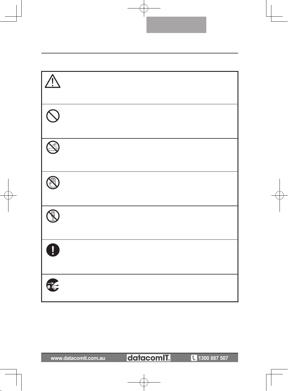
Symbols Used in this Manual
Name: Caution
Meaning:Indicates that the user must, without fail, pay careful attention
to any sentences or illustrations marked with a Caution
symbol.
Name: Prohibited
Meaning: Indicates that the user must pay careful attention to any
sentences or illustrations marked with a Prohibited (do not
do) symbol.
Name: Do not use in a bathroom or shower cubicle
Meaning: Indicates that using the product in a bathroom or shower
cubicle could result in injuries through a fire or electric
shock, and is strictly prohibited.
Name: Do not touch
Meaning: Indicates that touching the area could result in injuries
through electric shock, and is strictly prohibited.
Meaning: Do not disassemble
Meaning: Indicates that disassembling the product could result in
injuries through electric shock, and is strictly prohibited.
Name: Compulsory
Meaning: Indicates that the user must pay careful attention to any
sentences or illustrations marked with a Compulsory (must
do) symbol.
Name: Unplug the power plug and the AC adapter
Meaning: Indicates that the user must unplug the AC adapter.
Page 4
4
English
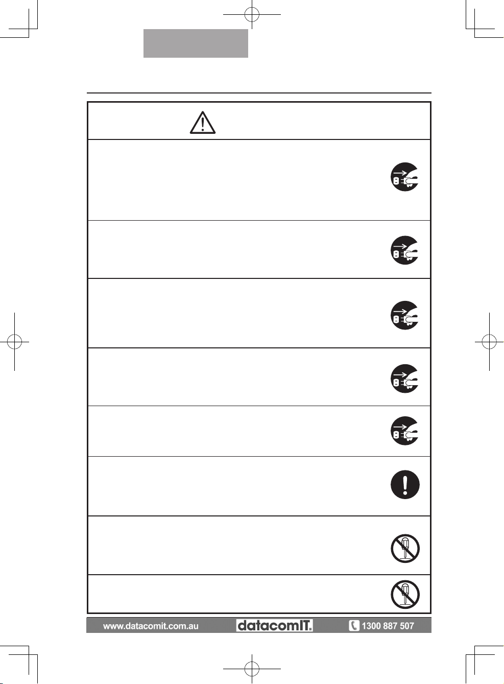
Warning
If for any reason smoke comes out of the product, or you notice any
unusual odors or sounds, immediately turn off the power switch on the
product and then unplug the power plug and AC adapter.
Continuing to use the product while it is operating unusually could result
in a fire or electric shock. Check that smoke is no longer coming out of
the product, and then contact your local dealer to request maintenance.
Do not attempt to service this product yourself.
If for any reason liquid is spilled into the product, immediately turn off the
power switch on the product and then unplug the power plug and AC
adapter.
Contact your local dealer immediately. Continuing to use the product in
this condition could result in a fire or electric shock.
If for any reason foreign objects enter the product, immediately turn off
the power switch on the product and then unplug the power plug and AC
adapter.
Contact your local dealer immediately. Continuing to use the product in
this condition could result in a fire or electric shock.
(Be extra careful if there are children in the area when using the product.
If f o r any rea son th ere is a bre akdo wn ca usin g no im ages t o be
projected, turn off the power switch on the product and then unplug the
power plug and AC adapter.
Then contact your local dealer to request maintenance. Continuing to
use the product in this condition could result in a fire or electric shock.
If for any reason the product is dropped or the cabinet is damaged, turn
off the power switch on the product and then unplug the power plug
and AC adapter. Then contact your local dealer. Continuing to use the
product in this condition could result in a fire or electric shock.
If the power plug or AC adapter cord is damaged (e.g. if the inside of
the cord is exposed or broken), contact your local dealer and request a
replacement.
Continuing to use the product in this condition could result in a fire or
electric shock.
Do not remove the back panel, cabinet, or cover from this product.
Doing so may expose you to dangerous voltage and could result in
electric shock.
Contact your local dealer for any internal inspections, maintenance, or
repair.
Do not remodel this device.
This could result in a fire or electric shock.
Page 5
5
English
Warning
Do not place this product on an uneven surface of unstable stand.It
could fall or topple over and result in an injury.
Do not place any heavy objects on the power plug or AC adapter, and
do not place this product on top of the cord.
The cord could be damaged and result in a fire or electric shock. (If the
cord is covered by a carpet, there are times when you may not notice
that a heavy object has been placed on the cord.)
Do not damage, process, pinch, twist, pull, or heat the power plug or AC
adapter.
The cord could be damaged and result in a fire or electric shock.
Do not touch the product, connector cable, power plug, or AC adapter
during a thunder storm. This could result in an electric shock.
Be sure to use the power plug or AC adapter supplied with the product.
This could result in a fire or electric shock.
Do not spill water or insert any foreign objects into this product.
This could result in a fire or electric shock. Pay particular attention when
using the product in rainy weather, during a snowfall, on the coast, or on
a water front.
Do not use in a bathroom or shower cubicle.
This could result in a fire or electric shock.
If there is dust on the prongs of the power plug or the connector surface,
turn off the power switch on the product, unplug the power plug, and
then remove the dust.
The drop in insulation for the power plug could result in a fire.
Keep batteries out of children's reach as there is a danger they could be
swallowed.
If a battery is swallowed, consult a doctor immediately as this could
result in suffocation or an obstacle to digestion etc.
Page 6
6
English
Attention
Whenever moving the product, turn off the power switch on the product
and then unplug the power plug and AC adapter. Move after checking
that the external connection cord is disconnected. Otherwise, the cord
could be damaged and result in a fire or electric shock.
For safety reasons, if this product is not used for a long time, be sure to
unplug the power plug and the AC adapter.
Otherwise, it could result in a fire.
Do not connect or disconnect the power plug or AC adapter with wet
hands.
Failure to do so could result in an electric shock.
Do not place the product in a damp or dusty location.
This could result in a fire or electric shock.
Make sure the power plug is securely inserted into the socket.
If it is not inserted correctly, it could generate excess heat and dust
could enter which could result in a fire.
Also, touching a prong of the power plug could result in electric shock.
Do not disconnect the power plug or AC adapter by pulling the cord.
Otherwise, the cord could be damaged and result in a fire or electric
shock.
Disconnect by pulling the power plug or AC adapter.
If the product is placed on a stand with casters, make sure the caster's
brakes are on. It could result in an injury if it moves and falls.
Do not place the product in a location where it could be exposed to
smoke, steam, or water droplets such as on a kitchen counter or near a
humidifier.This could result in a fire or electric shock.
Do not sit on, or place any heavy objects on, this product. Be extra
careful if there are any small children in the area when using the product.
It could result in an injury if it breaks.
Do not place the power plug or AC adapter cables next to a heater.
The cord covering could melt and result in a fire or electric shock.
The power plug is loose in the socket, even when it is fully inserted.
Ex c ess he a t coul d be gene r ated an d res u lt in a fi re. Re quest a
replacement socket from your local dealer or electrical appliance store.
Page 7
7
English
BEFORE YOU USE
n B e sur e to us e t h e pow e r c o rd app l ic ab le to yo u r loc a l p o w er
specifications. If the product was sold in Japan, use the AC adapter sold
with the product with 100 VAC and 50 or 60 Hz.
n W
hen storing the product, do not leave it under direct sunlight or by
heaters.
n
It may be discolored, deformed, or damaged.
n Do not place this product in any humid, dusty, salt bearing wind, or
vibrating locations.
Use it under the following environmental conditions:
Temperature: 0°C - 40°C (32°F - 104°F)
Humidity:
30% - 85% (No condensation)
n Use a soft, dry cloth for cleaning.
Do not use any volatile solvent such as thinner or benzene.
n Do not point the camera lens directly at the sun. It may be damaged and
you may not be able to take pictures.
n
Luminescent and Black Spots
There may be some pix e l s that do not properly operate due to
th e use of CMOS Area Imag e Sen s ors made- u p of man y pix els.
Though luminescent or black spots may be found on the screen, it is a
phenomenon peculiar to the CMOS Area Image Sensors and is not a
malfunction.
n F
ol low the guid elines bel ow to pre vent the uni t from droppi ng or
overturning.
•
Use the product on a stable base, desk, or table. Do not place the
product on an unstable base or slanted location.
• Place or wire the unit to prevent the AC adapter cord or video cable
from pulling.
n Carry the product by holding the lower part of the main unit in both
hands. Never hold the product by the column or the camera head.
Page 8

8
English
n Pay careful attention when using (including setting-up and storing) or
transferring the product to prevent the camera head from receiving any
shocks.
n Do
not bring any magnetic media such as FDs, magnetic cards, magnetic
tapes, prepaid cards, MOs, or MDs near to the magnetic sheet. The data
on the recorded media could be corrupted.
n W
hen a magnetic sheet is brought close to a cathode ray tube (Braun
tube), a speaker, a CD-player, a DVD player, or a cellular phone, etc.,
normal operation may be interrupted or failure may occur.
n Do
not look directly into the LED light. If you look directly into it at point-
blank range, your eyes may be injured.
n Transfer
the data from the SD card onto a device such as a PC to save
a backup copy. Malfunction of the product or repairs to it may cause the
data saved in the SD card to be deleted.
n If
this product is used for longer than the warranty period, its performance
and quality may deteriorate due to the lifetime of its parts. To purchase
replacement parts, consult the dealer from whom you purchased this
product or our branch/office near your location.
n Battery precautions:
If
this product is not going to be used for a long time, take the batteries
out of the remote control.
Do not use rechargeable batteries (e.g., Ni-Cd (NiCad batteries)).
Do not use new and old batteries or batteries of different types together.
Do not try to recharge or short-circuit the batteries.
W
hen disposing of used batteries, follow the instructions of your local
government.
I
nsert from one side and pay particular attention to the polarity (+/-
directions).
Be sure to use AAA batteries.
n If
any liquid from a battery leaks onto your skin or clothes, flush the area
with clean water immediately. If it gets into your eye, flush immediately
with clean water and then contact a doctor.
Page 9
9
CONTENTS
PART NAMES
AND
FUNCTIONS
SETTING UP STORING
OPERATION
PROCEDURE
VARIOUS
FUNCTIONS
AND
OPERATIONS
TROUBLE
SHOOTING
SPECIFICATIONS
English
IMPORTANT SAFEGUARDS ..................................................................2
BEFORE YOU USE ......................................................................................... 7
Contents ........................................................................................................9
1.PART NAMES AND FUNCTIONS ..................................................11
PART NAMES ................................................................................................11
Appearance ................................................................................................11
Functions .........................................................................................................12
Operating Panel ........................................................................................12
Rear panel ...................................................................................................14
Side panel ...................................................................................................15
Remote Control .........................................................................................16
Functions ....................................................................................................17
OSD (On Screen Display) ..........................................................................19
Camera Mode OSD Menu......................................................................21
SD Mode OSD Menu ...............................................................................25
SD ..................................................................................................................26
2. SETTING UP .......................................................................................28
Setting Up .......................................................................................................28
Connecting the AC adapter and Video cable .....................................30
3. STORING ...............................................................................................32
Storing ..............................................................................................................32
4. OPERATION PROCEDURE ............................................................. 34
Presentation using printed materials, etc. .........................................34
Presentation using printed materials, etc. ........................................35
(Using the stage) .........................................................................................35
Presentation using an SD card (commercially-available) .............. 36
Transferring images from the SD card to a USB-connected PC
.........40
Presentation using the supplied software with a USB-connected PC
.........42
Presentation using a Microscope ..........................................................43
Presentation using a Microscope (Installing the attachment supplied)
......45
Shooting a 3-D object ................................................................................47
Shooting wall surface or distant view...................................................48
5. VARIOUS FUNCTIONS AND OPERATIONS .........................49
Zoom .................................................................................................................49
Focus ................................................................................................................50
Zoom Focus ...............................................................................................50
Manual focus .............................................................................................51
Zoom Sync Focus ....................................................................................51
Illumination lamp ...........................................................................................52
Adjusting the brightness ...........................................................................53
Automatic brightness adjustment ....................................................53
Manual brightness adjustment ...........................................................53
Image selection .............................................................................................54
White Balance ...............................................................................................55
How to use [Auto] ...................................................................................55
Page 10
10
PART NAMES
AND
FUNCTIONS
SETTING UP STORING
OPERATION
PROCEDURE
VARIOUS
FUNCTIONS
AND
OPERATIONS
TROUBLE
SHOOTING
SPECIFICATIONS
English
How to use [One-Push] .........................................................................55
How to use [Manual]...............................................................................55
Save/call settings .......................................................................................56
How to save settings .............................................................................56
How to call settings ...............................................................................57
Highlight Function ........................................................................................58
Highlight settings ..................................................................................58
Highlight operations ..............................................................................59
Mask Function ...............................................................................................60
Mask settings ..........................................................................................60
Mask operations .....................................................................................60
Scroll Function ..............................................................................................61
Digital zoom settings ............................................................................61
Scroll operations .....................................................................................61
PinP (Picture in Picture) Function..........................................................62
PinP operations .......................................................................................62
Using a Desktop Recorder (Optional) ...................................................63
Connecting the desktop recorder ......................................................63
Operating the desktop recorder by remote control .....................63
6.TROUBLE SHOOTING ........................................................................64
Symptoms and Confirmation ....................................................................64
7.SPECIFICATIONS ............................................................................... 66
General .............................................................................................................66
Main Camera ..................................................................................................66
Illumination Device .......................................................................................67
Supplied Accessories .................................................................................68
Contact details ........................................................................................68
Page 11
11
PART NAMES
AND
FUNCTIONS
English
(8)
(9)
(1)
(2)
(3)
(7)
(6)
(4)
(5)
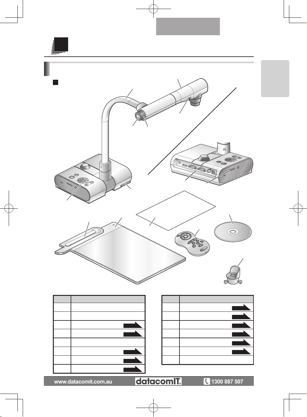
No Name No Name
(1) Camera head (9) Side panel
P.15
(2) Illumination lamp switch (10) Magnetic sheet
P.35
(3) Zoom dial
P.49
(11) Stage
P.35
(4) AF Button
P.50
(12) Anti-glare sheet
P.35
(5) Camera column (13) Remote control
P.16
(6) Operating panel
P.12
(14)
Microscope attachment
P.45
(7) Stage positioning
P.35
(15)
Image Mate CD-ROM
(8) Rear panel
P.14
(10)
(11)
(12)
(15)
(13)
(14)
Front
PART NAMES
Rear
Appearance
PART NAMES AND FUNCTIONS
1
Page 12
12
PART NAMES
AND
FUNCTIONS
English
Functions
(1)
(2)
(6)
(7)
(8)
(11)(13)
(3)
(9)
(4)(5)(14)
(10)(12)
Operating Panel
Page 13
13
PART NAMES
AND
FUNCTIONS
English
Name Function Name Function
(1)
POWER
(POWER ON/OFF
standby status)
To turn the power
ON/OFF.
Power ON:
Blue lamp
Power OFF
standby status:
Red lamp
(7) Image
select
(SD mode)
To switch the output
image to images
stored on the SD
card.
The SD Mode LED
is illuminated in SD
Mode.
P.54
(2)
OSD
Procedure
P.19
MENU
To show/hide the
OSD menu.
The LEDs for operation buttons are
not lit during OSD
menu display.
P.19
(8)
(CAMERA)
To switch the output
image to camera
image.
The LED is illuminated
when camera image is
selected as the output
image.
P.54
(3)
(Direction)
To select an OSD
menu item.
(9)
(PC)
To switch the output
image to the image
input to RGB IN.
The LED is illuminated when RGB IN
image is selected as
the output image.
P.54
(4)
(Decision)
To decide the
OSD item.
(10)
Brightness
Adjust
To brighten the
camera image.
P.53
(5)
(Pause)
To pause the
camera image.
Press this button
again to unpause
the video.
(11)
To darken the
camera image.
P.53
(12)
SD
mode
operation
When SD single
is displayed, it
returns to the
previous image.
In 4 x 4 display, the
cursor for selecting
the image returns
to the previous
image.
(6)
(Image save)
To save the image on the SD
card.
P.37
(13)
When SD single is
displayed, it moves to
the following picture.
When 4
x
4 is displayed, the cursor for
selecting the image
moves to the following image.
(14)
Change between
SD image single
display and 4 x 4
display.
Page 14
14
PART NAMES
AND
FUNCTIONS
English
(1)
(7)
(2)
(3)
(4)
(5)
(6)
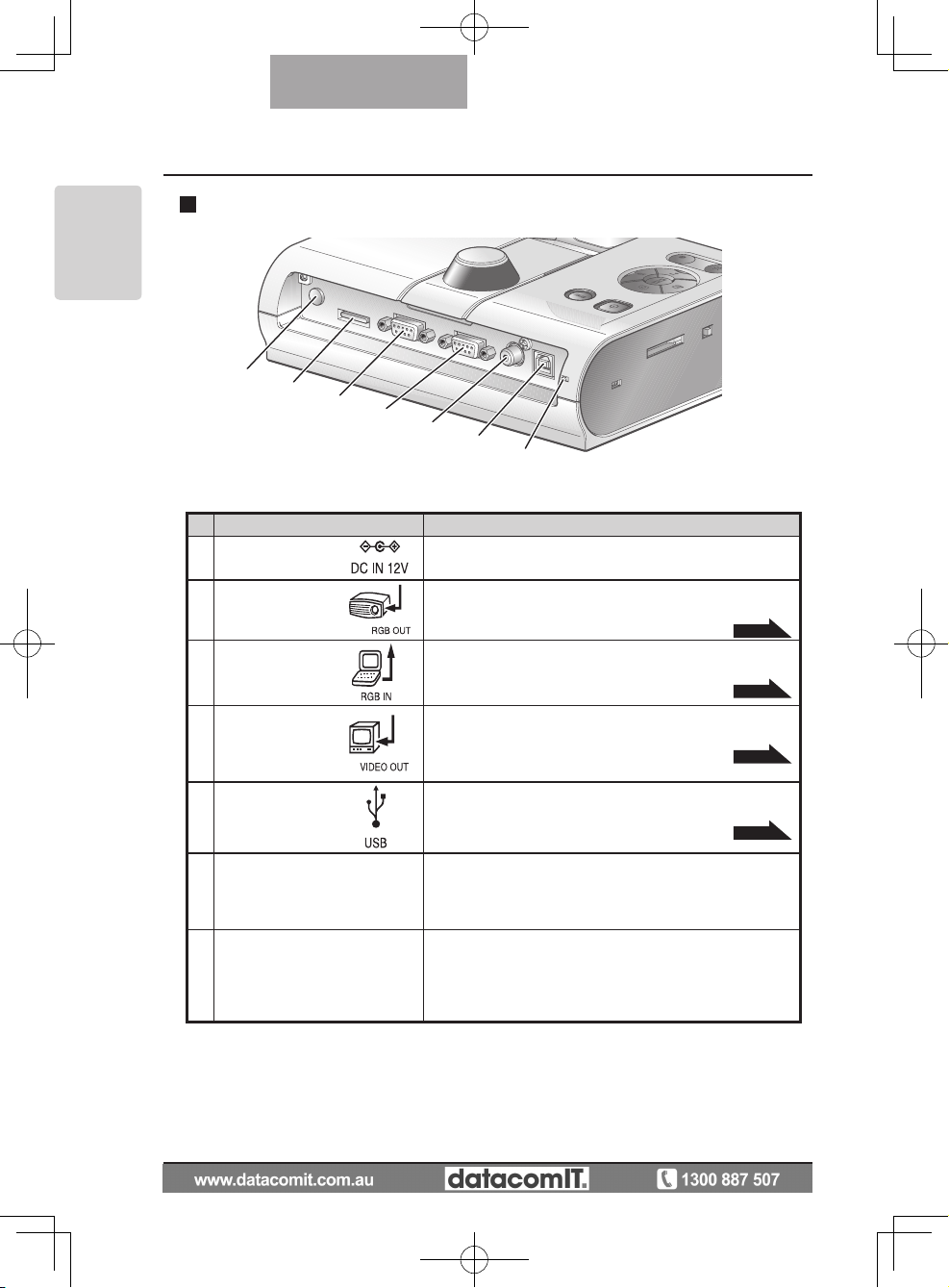
Name Function
(1) DC IN 12V
(Power Socket)
Plug-in for the AC adapter.
(2) RGB OUT
(Analog RGB
Output Terminal)
To output analog video signal to a projector, a PC monitor, or other RGB input device.
P.30
(3) RGB IN
(Analog RGB
Input Terminal)
To output the image input to this terminal when [PC] is
selected by Image select button.
P.30
(4) VIDEO OUT
(Composite
Video Output
Terminal)
To output images from the RCA pin-jack terminal to the
NTSC/PAL-system monitor (e.g., TV monitor).
P.31
(5) USB
(2.0 Compliant)
To transfer image or control the main unit using the software contained in the supplied Image Mate CD-ROM
by connecting with the PC.
P.42
(6) RESOLUTION
(Change Resolution Switch)
To change the resolution of the output analog image.
SXGA: 1280×1024
WXGA: 1280×800
XGA: 1024×768
(7) RECORDER
(Recorder Terminal)
Terminal to connect the optional desktop recorder via a
dedicated cable. By connecting to the desktop recorder, you can record camera images from this device.
Refer to the manual for the optional desktop recorder
for more details.
Rear panel
Page 15
15
PART NAMES
AND
FUNCTIONS
English
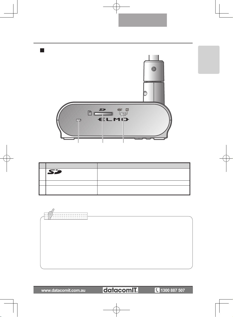
(1)(2) (3)
Name Function
(1)
(SD Card Slot)
To insert an SD card into the SD card slot.
Push the card again to remove the SD card.
(2) Security slot
(3) RGB/VIDEO Switch To change the output image to RGB or VIDEO.
• Factory setting: RGB
Side panel
N o t e
• Only one image can be output at a time; either [RGB OUT] or [VIDEO OUT]. ([RGB
OUT] and [VIDEO OUT] cannot be output simultaneously.
•
When the RGB/VIDEO switch is set to [VIDEO], the image input to [RGB IN] is not
output from [RGB OUT].
(Unable to operate the [PC] button on the main unit.
(Unable to r
ecord or playback from the optional desktop recorder.
• Enters [CAMERA] mode when the output is [RGB OUT] and [VIDEO] is set for [PC]
mode.
Page 16
16
PART NAMES
AND
FUNCTIONS
English
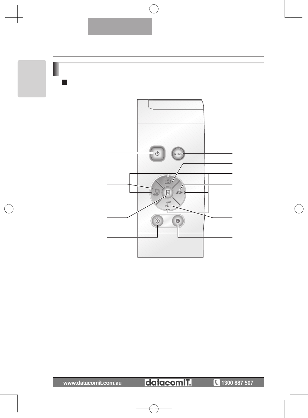
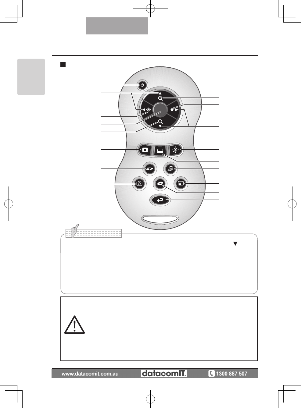
Remote Control
(1)
(2)
(5)
(6)
(12)
(11)
(14)
(17)
(16)
(18)
(6)
(4)
(3)
(10)
(13)
(15)
(7)(8)(9)
N o t e
• When setting the batteries, remove the battery case cover by pushing the [ ] mark
in the arrow direction on the back side of the remote control, and set 2 AAA batteries
in the case.
•
Insert from one side and pay particular attention to the polarity (+ / - directions).
• Do not use new and old batteries or batteries of different types together.
• Be sure to use AAA batteries.
• Replace the batteries with new ones at least once a year.
• Use the supplied batteries for an initial operation check. The operating life is not
guaranteed.
Warning
Because there is a ch a n c e that
small batteries could be ingested,
be su re to keep th em out of the
re a ch of chi l dr en. If a ba tt e ry
is sw a l lo we d, co n su lt a doc t o r
immediately as this could result
in suf focation or an obsta cle to
digestion etc.
Page 17
17
PART NAMES
AND
FUNCTIONS
English
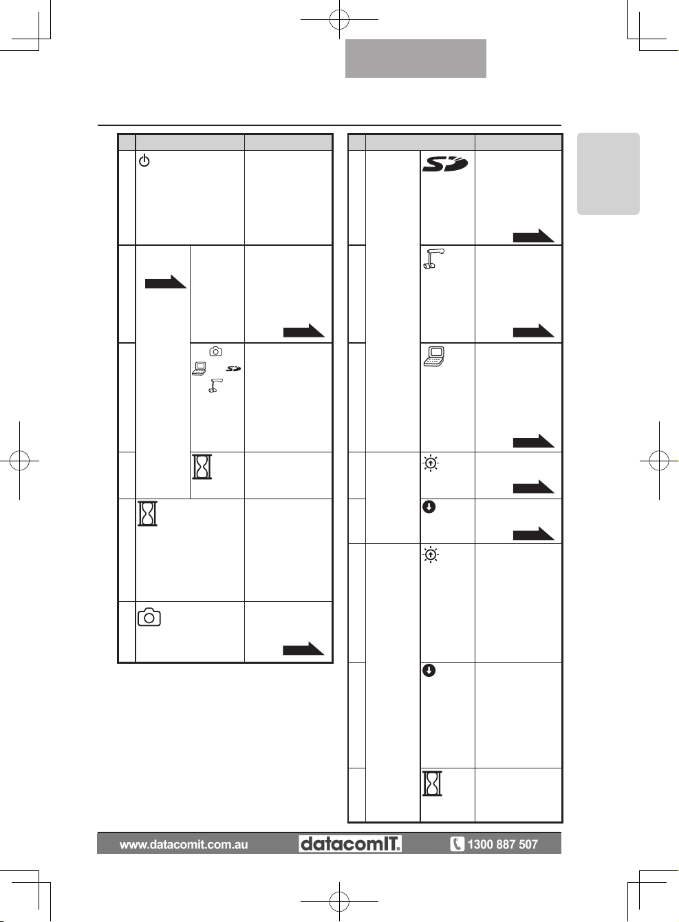
Functions
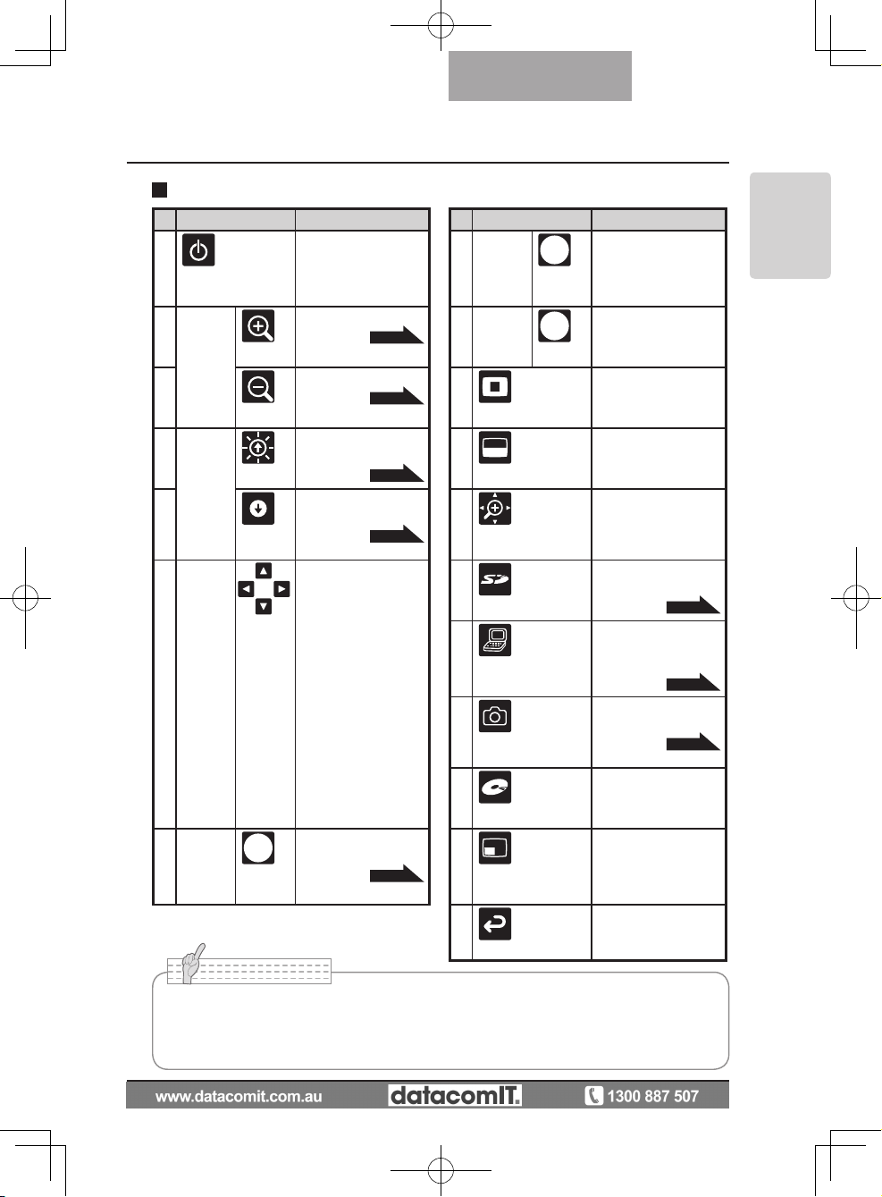
Name Function Name Function
(1)
(POWER ON/OFF
standby status)
To turn the power
ON/OFF.
(8) SD
Mode
operations
Change between SD
image single display
and 4 x 4 display. *2
(2)
ZOOM
(TELE)
To tele zoom.
P.49
(9)
Recorder
Mode
operations
To decide the OSD
cursor for the recorder.
(3)
(WIDE)
To wide zoom.
P.49
(10)
(Highlight)
To highlight part of
the image displayed.
*1
(4)
BRIGHT
NESS
(Brightness
adjust)
(Bright)
To brighten the camera image.
P.53
(11)
(Mask)
To mask an area of
the output image. *1
(5)
(Dark)
To darken the camera image.
P.53
(12)
(Scroll)
To enlarge the image
currently displayed
and move up, down,
left, and right. *1
(6)
SD mode/
highlight/
mask/
scroll
operations
(Direction)
To move forward/
backward through the
images saved in SD
mode.
Moves the highlight
section in highlight
mode, moves the
mask section in mask
mode, and moves the
displayed image in
scroll mode.
Moves the small
screen during PinP.
To decide the OSD
cursor for the recorder
in Recorder Mode.
(13)
(SD mode)
To switch the output
image to SD mode.
P.54
(14)
PC
To switch the output
image to the image
input to RGB IN.
P.54
(15)
(Capture)
To save the image
on the SD card.
P.37
(16)
(Recorder)
To operate an
optional desktop
recorder. *3
(7)
AF
(Auto Focus)
To automatically
focus the camera.
P.50
(17)
PinP
(Picture in Picture)
To display a still image as a small picture
while displaying a
camera image.
(18)
Back
To return the output
image to camera image.
N o t e
*1 This function can only be operated while displaying camera mode/SD mode.
(Cannot be operated in conjunction with other functions.)
*2 This function can only be operated while displaying SD mode.
*3 Cannot be operated when the desktop recorder is not connected.
Page 18
18
PART NAMES
AND
FUNCTIONS
English
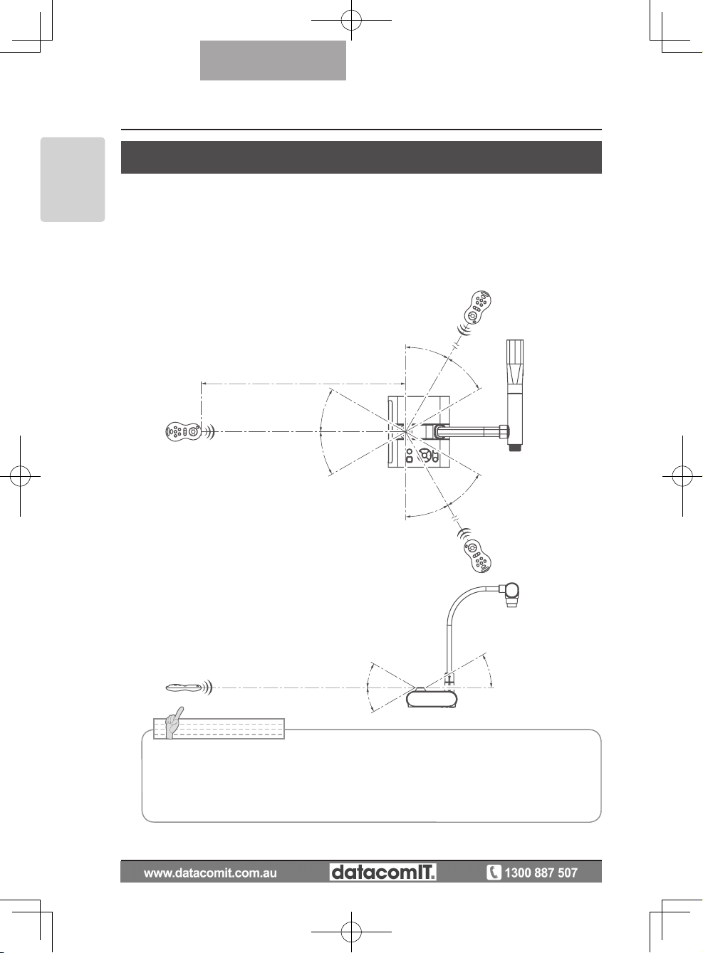
Remote control reception
Point the transmission unit of the remote control at the sensor unit located on the front of
the camera main unit, press the operation button for the intended operation, and operate
the camera main unit accordingly.
Receivable Range
Distance: Within approx. 7m from the front face of the remote control sensor unit.
Angle: Within 30º up, down, left, and right from the remote control sensor unit.
within 7m
30°
30°
30°
30°
30°
30°
30°
30°
30°
N o t e
• The receivable range may be shortened or narrowed and the laser beam from the
remote control may not be sensed depending on the surrounding circumstances
(e.g., sunlight, position adjacent to inverter fluorescent lamp). In this case, relocate
the receiving side or shield the sun light or fluorescent lamp.
Page 19
19
PART NAMES
AND
FUNCTIONS
English
OSD (On Screen Display)
OSD is used to display characters such as text and icons on a monitor or projection screen.
It displays this device's menu screens for various operations and settings.
In this manual, this is referred to as the OSD menu.
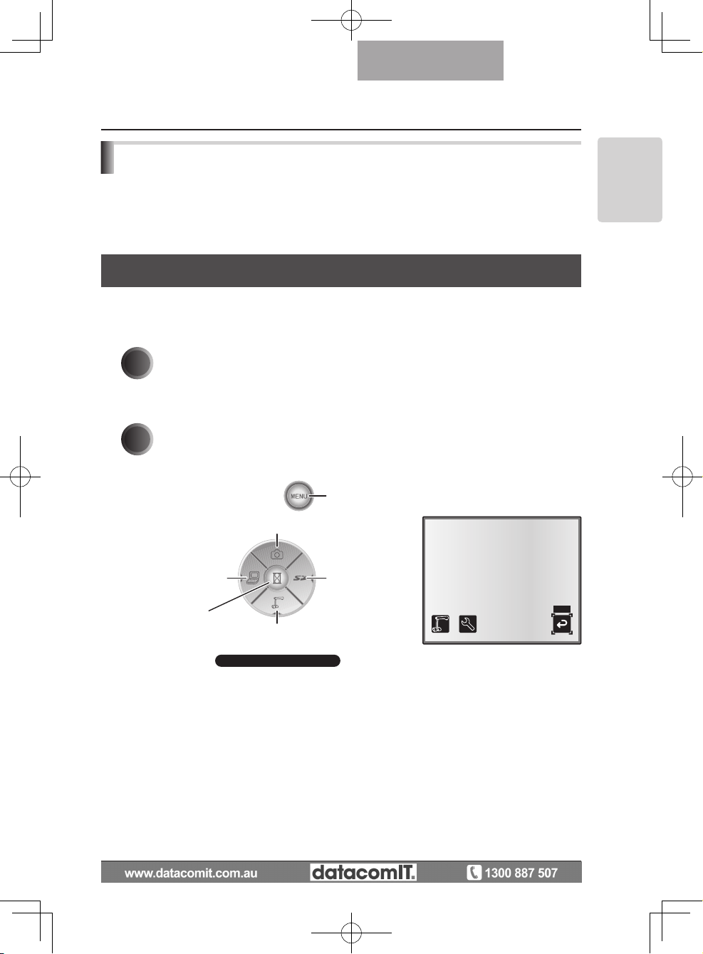
OSD Basic Operations
The following procedure shows button operations used when setting or operating via OSD.
n Operations for selecting and deciding icons
1
Press the [MENU] button on the front panel to display the OSD, and
then use the [↑↓←→] buttons to move to the icon you want to operate or
set.
2
Use the [Decision] button on the front panel to enter the setting value.
[Decision] button
[↑] button
Move the cursor up
[←] button
Move the cursor left
[→] button
Move the cursor right
[MENU] button
[↓] button
Move the cursor down
Front operating panel
BACK
Page 20
20
PART NAMES
AND
FUNCTIONS
English
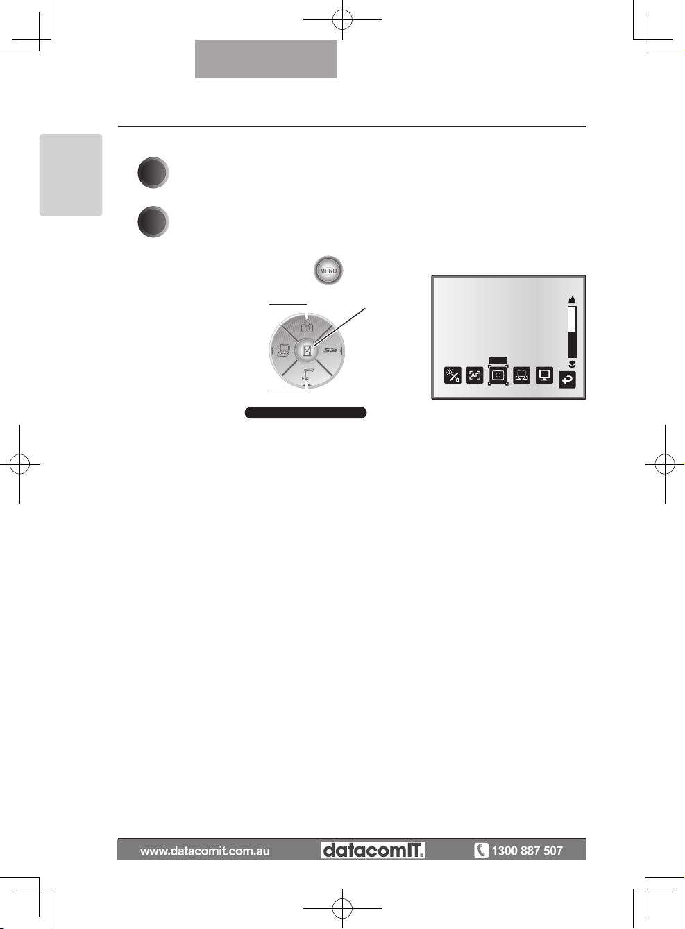
n Adjusting the level bar
1
Use the [↑↓] buttons on the front panel to adjust the setting value.
2
Use the [Decision] button on the front panel to enter the setting value.
Decide the
level bar setting
Increase the
level bar setting
Reduce the
level bar setting
Front operating panel
ピント
Page 21
21
PART NAMES
AND
FUNCTIONS
English
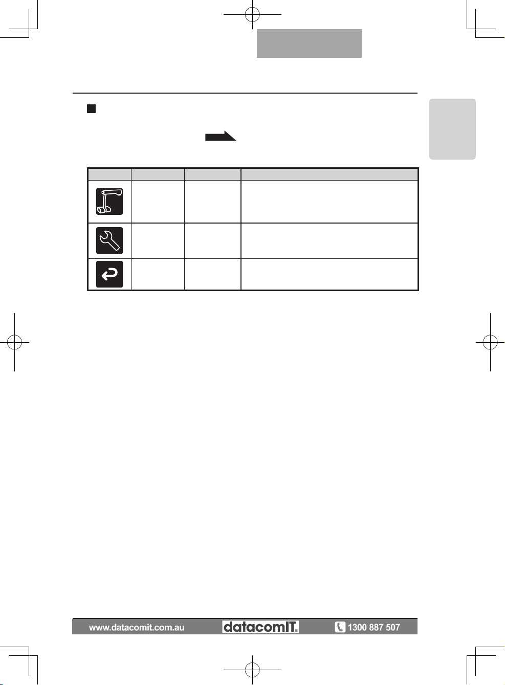
Icon
Name
Selection Item
Function Explanation
Image Setting
Image Setting
Menu
Displays the menu for adjusting and displaying
camera images.
Function
Setting
Function
Setting Menu
Displays the menu for function settings.
Back - Hides the OSD menu display.
After using Image select to change the output image to camera image, press the "MENU"
button to display the OSD menu.
P.54
Camera Mode OSD Menu
n Top menu
Page 22

22
PART NAMES
AND
FUNCTIONS
English
n
Image Setting Menu
Icon
Name
Conditions
Selection Item
Function Explanation
Brightness
Auto
To automatically adjust the brightness of
the camera image to suit the subject of
the image. You can adjust the amount
of auto adjustment.
Manual
To set the cam era i mage to a fi xed
brightness.
Reset
Brightness
Brightness
[Auto]
To reset the amount of auto adjustment
to the default setting.
AF Mode
Push
Press the AF button to automa tically
focus.
Zoom Sync
The focu s is auto matical ly adj us ted
when zooming.
Focus Use the level bar to fine-tune the focus.
White
Balance
Auto
To automatically adjust the white balance.
One-Push
To set the white balance to a fixed setting after carrying out automatic correction.
Manual
To manually adjust the [R-Gain] and [BGain].
R-Gain
Tint
[Manual]
-
Use the level bar to adjust the [R-Gain]
for the camera image. Use [↑] or [↓] to
increase or decrease the red tint.
B-Gain
Tint
[Manual]
-
Use the level bar to adjust the [B-Gain]
for the camera image. Use [↑] or [↓] to
increase or decrease the blue tint.
Image
Mode
Text1
To c lea rly rep ro duc e b lack & w hit e
subjects such as characters and lines.
Use this when shooting materials such
as documents or text based data. The
effect grows stronger as the number is
increased.
Text2
Text3
Graphics1
To beautifully reproduce color subjects.
Use this when shooting materials such
as color figures and photo based data.
Graphics2
At t im es it i s eas ie r to view imag es
when using a DLP projector.
* The "
" symbol indicates the factory settings.
Page 23

23
PART NAMES
AND
FUNCTIONS
English
Icon
Name
Conditions
Selection Item
Function Explanation
Edge Effect
Image Mode
[Graphics1]
Low
Emphasizes the outline of images making them crisper and clearer.
Middle
High
Gamma
Image Mode
[Graphics1]
Low
To change the tone reproduction characteristics of the image. (The effect
grows stro nger as the number is increased.)
Middle
High
Image
Rotation
Of
f
Turn ON to rotate the camera image by
180º.
On
Microscope
Off
SE T to ente r Mic ros c ope Shoot i ng
mode.
Set
Color/B&W
Color To output a color camera image.
B&W
To output a black & white camera image. To make the image easier to view,
select this when shooting black & white
documents etc.
Posi/Nega
Posi
To output a positive camera image.
Nega To output a negative camera image.
Back
To return to the OSD menu display top
menu.
* The "
" symbol indicates the factory settings.
Page 24

24
PART NAMES
AND
FUNCTIONS
English
n
Function Setting Menu
Icon
Name Selection Item Function Explanation
USB Mode
Mass Storage
After connecting to a PC via a USB cable, data on the SD card loaded in this
device can be sent to the PC.
Application
(∗)
After connecting to a PC via a USB cable, it is possible to take control of this
device and import images by PC.
Flickerless
60Hz
(∗)
To reduce fluorescent lamp flickering
du e t o the power suppl y f re que ncy.
Select the same value as used for the
power supply frequency.
50Hz
Video Format
NTSC (∗) Video is output using the NTSC system.
PAL Video is output using the PAL system.
Highlight
Darkness -
To set the darkness of the masked section using the level bar, except for when
using the Highlight display.
Size - To set the size of the Highlight display.
Mask Darkness -
To set the darkness of the masked section using the level bar.
Scroll
x2
To set the electron expansion magnification for scroll display to 2x, 3x, or 4x.
x3
x4
Preset
1
To store preset settings in the memory of
the selected number.
2
3
Power On
The preset settings stored here are automatically called the next time the power
is turned on.
Exit
Exits without saving settings.
* The " " symbol indicates the factory settings.
N o t e
• Selecting [Power On] or [Default] from [Call] provides the factory settings when the
power is turned on. However, for items with (∗) in the [Factory Settings] column, the
last status set is maintained.
Page 25

25
PART NAMES
AND
FUNCTIONS
English
Icon
Name Selection Item Function Explanation
Call
1
To call the setting saved in the memory
of the selected number.
2
3
Power On
Cu rrent setti ngs are ret urn ed to the
Power On status. (∗)
Default
Current settings are returned to the Default status. (∗)
Exit Exits without calling settings.
Guide
On
When turned on, the device's operating
status and an explanation of the icons is
displayed on the screen.
Off
Language
Japanese
(∗) To display the OSD menu in Japanese.
English To display the OSD menu in English.
Back
To return to the OSD menu display top
menu.
* The "
" symbol indicates the factory settings.
After using Image select to change the output image to SD Mode, press the "MENU" button
to display the OSD menu.
P.54
SD Mode OSD Menu
Icon
Name Selection Item Function Explanation
SD SD Menu
To display the setting menu for SD images.
Slide Show Slide Show Menu
To display t he setting me nu for Slide
Show.
Back - Hides the OSD menu display.
n OSD Top menu
N o t e
• Selecting [Power On] or [Default] from [Call] provides the factory settings when the
power is turned on. However, for items with (∗) in the [Factory Settings] column, the
last status set is maintained.
Page 26

26
PART NAMES
AND
FUNCTIONS
English
Icon
Name Selection Item Function Explanation
Delete
Current
To delete the image currently displayed.
Locked images cannot be deleted. Select [Yes] to format or [No] to cancel.
All
To delete all images stored on the SD
card. Locked images cannot be deleted.
Select [Yes] to format or [No] to cancel.
Exit Exit without deleting anything.
Lock
Current
To lock the image currently displayed.
Locked images cannot be deleted.
All
To lock all images stored on the SD card.
Locked images cannot be deleted.
Exit Exit without locking anything.
Unlock
Current
To unlock the image currently being displayed.
All
To unlock all images stored on the SD
card.
Exit Exit without unlocking anything.
Format Media
To format an SD card. When this item is
selected, a confirmation message is displayed. Select [Yes] to format or [No] to
cancel.
When formatting, all of the data on the
SD card, including locked images, is deleted. Check before formatting the card.
Back
To return to the OSD menu display top
menu.
On this menu, when any item except for [Back] is selected, a [Yes] or [No] confirmation
message is displayed. Select [Yes] to perform the operation, or [No] to cancel.
SD Menu
Page 27

27
PART NAMES
AND
FUNCTIONS
English
n
Slide Show Menu
Icon
Name Selection Item Function Explanation
Start Slide
Show
To start a slide show.
Interval
5sec
The image changes at the interval set
when a slide show is performed.
10sec
15sec
30sec
Select
All
To use all images stored on the SD card
for the slide show.
Locked Only
To use only locked images from the images stored on the SD card for the slide
show.
Repeat
Off The slide show is only shown once.
On The slide show is repeated.
Order
Forward
To give a slide show in ascending order
of serial No.
Backward
To give a slide show in descending order
of serial No.
Back
To return to the OSD menu display top
menu.
* The "
" symbol indicates the factory settings.
Page 28

28
SETTING UP
English
Setting Up
1
Tu r n th e ca m er a co l um n in th e
direction shown in the figure.
2
Rotate the camera head.
90°
N o t e
•
Never turn the column in the opposite direction.
•
Be sure to ho ld the colu mn when tur ning it.
Never hold the camera head.
N o t e
• Carr y t he product by holding the lower part
of the main unit in both hands. Never hold the
product by the column or the camera head.
• Pay
attention to prevent the camera head from
knocking against a desk or the like.
SETTING UP
N o t e
• Proper set up position of the camera head is
as shown in the figure on the right. Never apply
excessive force to the camera.
180°
2
Page 29

29
SETTING UP
English
3
A f t e r c o n n e c t i n g t h e i m a g e
c a bl e, an d c o nn ec t i n g t h e AC
ad apter to the DC IN 12 V (Power
S o c k e t) , pl ug t h e AC a d a pt e r
i n t o t h e w a l l s o c k e t .
P.30
(The [POWER
] button is illuminated
red.)
4
P r e ss t he [ PO W E R ] b u t t o n
o n t h e o p e r a t i n g p a n e l o r
the r
emote control.
After the [POWER
] button flashes
blue, [Power On] is illuminated a few
seconds later.)
N o t e
• Do not operate this device while it is flashing.
Page 30

30
SETTING UP
English
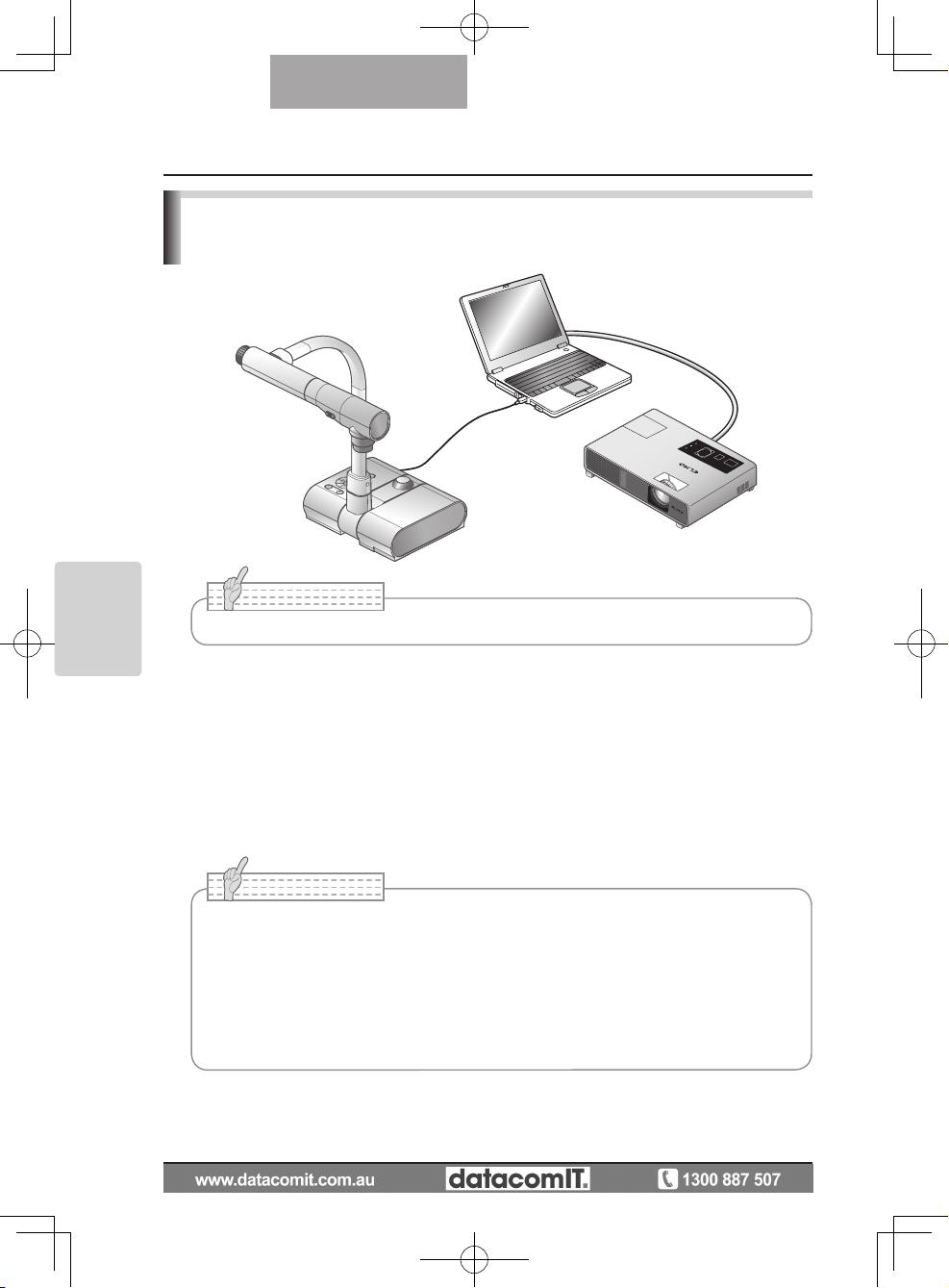
Connecting the AC adapter and Video cable
(1) Connecting to the unit with analog RGB input terminal equipped.
Connect the supplied analog RGB cable to the [RGB OUT] terminal on the rear panel.
•
The display position may be displaced from the center of the screen. In such a case,
adjust the horizontal and vertical positions manually from the connected device.
•
Vertical stripes may appear on the projector or PC monitor screen. This can be mitigated
by manually adjusting the dot clock from the connected device of the unit with analog
RGB output terminal equipped.
(
2) Connecting to the unit with analog RGB output terminal equipped.
Connect the supplied or commercially available analog RGB cable to the [RGB IN] terminal
on the rear panel.
(1) RGB OUT
terminal
· To projector
· To PC monitor
(5) DC IN 12V terminal
· To power plug
(6) RECORDER terminal
· To desktop recorder
(sold seperately)
(3) VIDEO OUT
terminal
· To TV monitor
(2) RGB IN
terminal
· To PC
(4) USB
terminal
· To PC
N o t e
• When using a laptop PC with external output mode capability, set the laptop PC to
external output mode after pressing the manual operation button [PC] on the main
unit.
Page 31

31
SETTING UP
English
(3) Connecting to the unit with a composite video input terminal equipped.
Connect a commercially available RCA pin plug video cable to the [VIDEO OUT] terminal
on the rear panel.
(
4) Connecting to the PC with a USB cable.
Connect the supplied or commercially available USB cable to the [USB] terminal on the rear
panel.
N o t e
• We recommend using a USB 2.0 compliant USB cable.
•
If you plug into a USB connector with the power on, the PC may not recognize this device.
• Depending on the USB environment used by the PC or peripheral equipment using
the USB 2.0 compliant cable, image transfer may be disrupted.
•
Operation is not guaranteed for all environments.
N o t e
• Only one image can be output at a time; either [RGB OUT] or [VIDEO OUT]. For more
information on switching the image output, refer to "RGB/Video Switch".
P.15
• To pro tect the unit and peripher al devices, unplug the power plug and the AC
adapter, and turn off all other devices before connecting the video cable.
•
When plugging in or unplugging the power plug, the AC adapter, or video cable, hold the plug
of the cable.
(5) Connecting the AC adapter.
Connect the DC plug of the supplied AC adapter to the [DC IN 12V] terminal on the rear
panel before inserting the AC adapter in an outlet.
n Specifications of the analog RGB input terminal of this product.
Signal allocation
10
9 8 7 6
5 4 3 2 1
15 14 13
DSUB 15P shrink terminal (Female)
12 11
Video signal: Analog 0.7V (p-p) with 75Ω terminated
Horizontal synchronized signal: TTL level (Positive/negative polarity)
Vertical synchronized signal: TTL level (Positive/negative polarity)
Pin assignment
Pin No. Name Pin No. Name Pin No. Name
1
Video signal (Red)
6 GND (Red) 11 GND
2
Video signal (Green)
7 GND (Green) 12 N.C
3
Video signal (Blue)
8 GND (Blue) 13
Horizontal syn-
chronized signal
4 N.C 9 N.C 14
Vertical synchro-
nized signal
5 GND 10 GND 15 N.C
Page 32

32
STORING
English
Storing
1
Press th e [POWER ] button on the
operating panel or the remote control.
(H o l d dow n th e [PO W E R ] bu t t on fo r
ap p ro x imat e ly two secon d s or mor e. The
lamp changes form blue to red and the power
switches off.)
2
Unplug the AC adapter from the wall
soc k et. The n , di scon n ec t th e AC
adapter and the video cable.
3
Turn the camera head in the direction
shown in the figure.
90°
STORING
3
N o t e
• Before storing the main unit, be sure to turn the
power off.
Page 33

33
STORING
English
4
Turn the camera column in the direction
shown in the figure.
180°
N o t e
• Never turn the column in the opposite direction.
• Be sure to hold the column when turning it. Never hold the camera head.
•
The proper storage position for the camera head is shown in the figure above. Never
apply excessive force to the camera.
• Pay attention to prevent the camera head from knocking against a desk or the like.
• Unplug the power cord and the AC adapter when the unit is not being used.
• Turn off the illumination lamp switch when folding the main unit.
Page 34

34
OPERATION
PROCEDURE
English
Presentation using printed materials, etc.
N o t e
• Before connecting the main unit to other devices, be sure to turn off the power for all
of the devices.
• W
hen copying B&W characters or documents etc., use TEXT1 to 3 from the OSD
(Camera image) as the image mode.
A better image may be produced by selecting Graphics1 mode with DLP projector
.
• When con ne cted to a DL P projector, selec t the image mode accord ing to th e
displayed image as both text and photos can be beautifully reproduced by switching
to Graphics2 mode.
n Setting the main unit
Set the main unit as shown in the figure above. Then connect it to a projector or a PC
monitor, and turn on the power for the main unit.
n Adjusting the size
Place an object on the stage, and then adjust the zoom dial on the main unit or the zoom
buttons [
/
] on the remote control so that the part you want to shoot fits the screen
size.
P.49
n Adjusting the focus
Press the [AF] button on the main unit or on the remote control to focus the camera on the
object.
P.50
n Adjusting the brightness
Press the [BRIGHTNESS
]/[BRIGHTNESS ] buttons on the operating panel or on
the remote control to adjust the image brightness.
P.53
n Turning the illumination lamp ON/OFF
Move the illumination lamp switch on the main unit to the left/right to turn it ON/OFF.
OPERATION PROCEDURE
4
Page 35

35
OPERATION
PROCEDURE
English
Presentation using printed materials, etc.
(Using the stage)
You can give an effective presentation by using the supplied stage, magnetic sheet, and antiglare sheet.
n Setting the main unit
Attach the stage to the main unit in the specified position as shown in the figure above.
Then connect the main unit to a projector or a PC monitor, and turn on the power for the
main unit.
•
To prevent the printed materials, etc. from moving, use the supplied magnetic sheet to
properly fix the printed materials, etc. on the stage.
n Adjusting the size
Place an object on the stage, and then adjust the zoom dial on the main unit or the zoom
buttons [
/
] on the remote control so that the part you want to shoot fits the screen
size.
P.49
n Adjusting the focus
Press the [AF] button on the main unit or on the remote control to focus the camera on the
object.
P.50
n Adjusting the brightness
Press the [BRIGHTNESS
]/[BRIGHTNESS ] buttons on the operating panel or on
the remote control to adjust the image brightness.
P.53
n Turning the illumination lamp ON/OFF
Move the illumination lamp switch on the main unit to the left/right to turn it ON/OFF.
N o t e
• When shooting glossy documents etc., the images may be hard to see due to glare
etc. In this case, place the supplied Anti-glare sheet on the reflecting section to
reduce the amount of reflection and make the image easy to see.
Page 36

34
OPERATION
PROCEDURE
English
Presentation using printed materials, etc.
N o t e
• Before connecting the main unit to other devices, be sure to turn off the power for all
of the devices.
•
When copying B&W characters or documents etc., use TEXT1 to 3 from the OSD
(Camera image) as the image mode.
A better image may be pr
oduced by selecting Graphics1 mode with DLP projector.
• When con ne cted to a DL P projector, selec t the image mode accord ing to th e
displayed image as both text and photos can be beautifully reproduced by switching
to Graphics2 mode.
n Setting the main unit
Set the main unit as shown in the figure above. Then connect it to a projector or a PC
monitor, and turn on the power for the main unit.
n Adjusting the size
Place an object on the stage, and then adjust the zoom dial on the main unit or the zoom
buttons [
/
] on the remote control so that the part you want to shoot fits the screen
size.
P.49
n Adjusting the focus
Press the [AF] button on the main unit or on the remote control to focus the camera on the
object.
P.50
n Adjusting the brightness
Press the [BRIGHTNESS
]/[BRIGHTNESS ] buttons on the operating panel or on
the remote control to adjust the image brightness.
P.53
n Turning the illumination lamp ON/OFF
Move the illumination lamp switch on the main unit to the left/right to turn it ON/OFF.
OPERATION PROCEDURE
4
Page 37

37
OPERATION
PROCEDURE
English
n Saving the image
(1) Press the [
] button on the operating panel or the [
] button on the remote control
to switch the output image to the camera image.
(2) Make sure that the OSD is not displayed, and then press the [
] button on the
operating panel or on the remote control.
(3) Saving begins when the [
] mark is displayed on the screen. Saving is complete when
the symbol disappears.
N o t e
• Zoomed images cannot be saved during digital zooming. However, images which are
zoomed to the maximum [ZOOM-IN
] limit within the range of the optical zoom can
be saved.
•
Image data cannot be recorded with the correct date and time.
• Be sure to try shooting and confirm that the images are saved correctly beforehand.
If images cannot be saved normally due to some problem with this camera or the SD
card, ELMO is not liable to compensate for such failure.
•
The [
] mark is only displayed on the screen when [Function Setting] → [Guide] is set to ON
from the Camera OSD menu.
• When the SD card is write-protected, images cannot be saved in the SD card.
• If the SD card is full when recording, an [X] mark is displayed on the screen. Delete
any unnecessary images or use another SD card.
•
Never remove the S D card while it is reading or wr it in g data. This may caus e
malfunctions to occur.
n Displaying the image
There are two display modes for SD images. You can use Single display to display one
image only, or 4 x 4 display to display 16 images.
Single display
(1)
Make sure that the OSD is not displayed, and then press the [ ] button on the
operating panel or on the remote control. The output image changes to SD mode, and the
images stored on the SD card are displayed as single images.
(2) Make sure that the OSD is not displayed, and then press the [ ] button on the
operating panel or the [
] button on the remote control to change to the next image.
Press the [
] button on the operating panel or the [ ] button on the remote control
to return to the previous image.
(3)
You can zoom in or out of the image being displayed by using the zoom dial on the
main unit, and you can reset zoom in/out by using the AF button on the main unit.
◦
N o t e
• When an SD image is enlarged, the Scroll function cannot be used. If you want to
use the Scroll function, press the AF button to reset the image enlargement, and then
scroll.
Page 38

38
OPERATION
PROCEDURE
English
Changing display mode
(1) During Single display in SD Mode, make sure that OSD is not displayed, and then
press the [
] button on the operating panel or the [AF ] button on the remote
control to change the display from Single display to 4 x 4 display.
(2)
Press the [
] and [ ] buttons on the operating panel or the [ ] and [ ] buttons
on the remote control to move the image selection cursor.
(3)
Press the [
] button on the operating panel or the [AF ] button on the remote
control to display the image selected with the image selection cursor in Single
display.
n Deleting, locking, and unlocking images
(1)
Make sure that the OSD is not displayed, and then press the
[ ]
button on the
operating panel or on the remote control. The output image changes to SD mode,
and
the images stored on the SD card are displayed as single images. When you want to
work in 4
x
4 display, press the [
] button on the operating panel or the [AF ] button
on the remote control to change to 4 x 4 display.
(2)
Use the [
] / [ ] buttons on the operating panel to select the image you want to
delete.
In Single display, the image you want to delete is displayed. In 4 x 4 display, use the
image selection cursor to select the image you want to delete.
(3)
Press the [MENU] button on the operating panel to display the SD Mode OSD menu.
Deleting images
From the OSD menu, select [SD] → [Delete].
To delete the image currently selected, select [Current]. To delete all images, select [All].
Select [Yes] to start deleting. (If you do not want to delete, select [No].)
Locking images
From the OSD menu, select [SD] → [Lock].
To lock the image currently selected, select [Current]. To lock all images, select [All].
Unlocking images
From the OSD menu, select [SD] → [Unlock].
To unlock the image currently selected, select [Current]. To unlock all images, select [All].
◦
◦
◦
◦
Page 39

39
OPERATION
PROCEDURE
English
n Formatting the SD card
When you need to format the SD card, insert the SD card into this product, and execute
formatting.
(1)
Make sure that the OSD is not displayed, and then press the [
]
button on the
operating panel or on the remote control to switch the output image to SD mode.
(2)
Press the [MENU] button on the operating panel to display the SD Mode OSD menu.
(3) From the OSD menu, select [SD] → [Format Media].)
(4)
Select [Yes] to start formatting. (If you do not want to format, select [No].
n Slide Show
(1)
Make sure that the OSD is not displayed, and then press the [ ] button on the
operating panel or on the remote control to switch the output image to SD mode.
(2) Press the [MENU] button on the operating panel to display the SD Mode OSD menu.
(3) From the OSD menu, select [Slide Show] → [Start Slide Show].
(4)
When any button (excluding the [POWER
] button) on the operating panel or the
remote control is pressed, the slide show stops.
•
You can set Interval, Repeat, or Order from the Slide Show menu of the OSD.
N o t e
• When [Mass Storage] is set from [Function Setting] → [USB Mode] on the OSD menu
and the product is connected to a PC, you cannot delete, lock, or unlock SD images
or format an SD card.
• Do not tur
n off the power while formatting the SD card.
Page 40

40
OPERATION
PROCEDURE
English
Transferring images from the SD card to a USBconnected PC
Whe n t his product is conne cted to a PC via USB, image data on the SD card can be
transferred to the PC.
The Operating System (OS) for the connected PC should be Microsoft Windows 2000 (SP4 or
later) / XP (SP2 or later) / Vista.
(1)
Turn on the power supply to this product and to the PC.
(2) Connect this product to the PC with the supplied USB cable.
N o t e
• Set [USB Mode] to [Mass Storage] on the OSD Camera settings menu.
• I
nsert the SD card with the label facing up. Forcing it into the slot in the wrong
orientation may cause a malfunction.
N o t e
• When this product is connected to the PC for the first time, the required drivers are
installed automatically using the plug-and-play function of Windows. From the second
time and thereafter, the drivers are no longer installed.
Page 41

41
OPERATION
PROCEDURE
English
N o t e
• An SD card set in this product cannot be save d, deleted, locked, unlocked, or
formatted with image data from the PC.
•
Image data cannot be recorded with the correct date and time.
• When the operating panel or the remote control is in operation, do not connect or
disconnect the USB cable, as this could cause the product to malfunction. This may
cause malfunctions to occur.
•
Do not switch [USB Mode] on the OSD when this product is in USB-connection.
• We recommend using a USB 2.0 compliant USB cable.
• Depending on the USB environment used by the PC or peripheral equipment using
the USB 2.0 compliant cable, image transfer may be disrupted.
•
Operation is not guaranteed for all environments.
• When [USB Mode] has been set to [Mass Storage] and a USB cable has been
connected to the PC, an SD card cannot be deleted, locked, unlocked, formatted,
and saved with image data on this device.
(3)
This product is recognized as a removable disk. You can view the image data on an SD
card on the PC's viewer software.
•
The image data is stored in JPEG format in the following folders:
My Computer
DCIM
Removable disk
100_ELMO
IMAG0001.JPG
IMAG0002.JPG
•
•
•
Page 42
42
OPERATION
PROCEDURE
English
Presentation using the supplied software with a
USB-connected PC
N o t e
• When the operating panel or the remote control is in operation, do not connect or
disconnect the USB cable, as this could cause the product to malfunction.
•
We recommend using a USB 2.0 compliant USB cable.
• Depending on the USB environment used by the PC or peripheral equipment using
the USB 2.0 compliant cable, image transfer may be disrupted.
•
Operation is not guaranteed for all environments.
“Image Mate” can be found on the supplied CD-ROM.
The "Image Mate" and TWAIN driver "Image Mate TWAIN" software for controlling this device
can be found on the CD-ROM and allows you to perform the following functions.
• Transfer moving/still images to the PC
• Operate this product from the PC
For information such as PC hardware requirements, OS type, software guides, and the
"Image Mate" installation manual, see the "HELP folder" on the CD-ROM.
N o t e
• Set [USB Mode] to [Application] on the OSD.
Page 43

43
OPERATION
PROCEDURE
English
n Setting a microscope
Place an ob ject such as a prepared slide on the microscope, and t hen l ook into the
microscope and adjust the focus.
Install the supplied microscope attachment.
P.45
n Setting the main unit
Connect the main unit to a projector or a PC monitor and then turn on the power for the
main unit.
n Changing to Microscope mode
From the OSD, select [Microscope] → [Set].
n
Adjusting the focus
The [AF] button on the main unit or on the remote control focuses the camera on the object.
n Adjusting the brightness
Adjust the brightness with the mirror on the microscope.
Presentation using a Microscope
Adjust
Adjust
N o t e
• Be careful not to hit the main unit lens with the microscope attachment.
• When changing to microscope mode, [Graphics1] is automatically selected as the
[Image Mode].
Page 44

44
OPERATION
PROCEDURE
English
n Adjusting Zoom
By rotating the zoom dial on the main unit, you can adjust the angle of the zoomed image.
n
Closing microscope mode
From the OSD, select [Microscope]
→ [Off].
N o t e
• When using the document camera straight after using the microscope, set [Set] →
[Off] in the OSD.
•
When setting [Set]
→ [Off] in the OSD, [Image Mode] returns to the [Image Mode]
selected before changing to the microscope mode.
•
In Mic ro sco pe Mode , the bri ght nes s does not chang e eve n if y ou pres s the
[BRIGHTNESS
]/[BRIGHTNESS ] button on the operating panel.
Page 45

45
OPERATION
PROCEDURE
English
Presentation using a Microscope (Installing the
attachment supplied)
1
Place the object you want to view on
the microscope, and then look into
the microscope and adjust the focus.
Stand the microscope up straight.
2
C o v e r t h e e y e p i e ce w i th t h e
microscope attachment.
3
Fix the center of the cross and the
center of the eyepiece together with
the screw.
Align the center
Page 46

46
OPERATION
PROCEDURE
English
4
Ho r izontal l y slide th e mi croscop e
attachment and the lens for the main
unit together.
5
Sli d e in from the side and adjust
the lens for the main unit to the top
surface of the microscope attachment.
N o t e
• The microscope attachment can be used when the eyepiece is 20 to 28 mm. When
using an eyepiece of a different size, shoot without using the microscope attachment.
Page 47

47
OPERATION
PROCEDURE
English
Shooting a 3-D object
By adjusting the angle of the camera column and the camera head, a 3-D object can be shot
from the side.
Adjust
Adjust
Adjust
n Setting the main unit
Connect the main unit to a projector or a PC monitor, and then turn on the power for the
main unit. Adjust the angle of the camera column and the camera head as shown in the
above figure to shoot the 3-D object.
n Adjusting the size
Adjust the zoom dial on the main unit or the zoom buttons [
/
] on the remote
control so that the part of the object you want to shoot fits the screen size.
n Adjusting the focus
Press the [AF] button on the main unit or on the remote control to focus the camera on the
object. In cases where the object cannot be brought into focus, select [Focus] from the
OSD and use [Manual] to focus.
P.50
n Adjusting the brightness
Press the [BRIGHTNESS
] and [BRIGHTNESS ] buttons on the main unit to adjust
the image brightness.
P.53
n Turning the illumination lamp ON/OFF
Move the illumination lamp switch on the main unit to the left/right to turn it ON/OFF.
N o t e
• The focus can be achieved from 50mm - .
Page 48

48
OPERATION
PROCEDURE
English
Shooting wall surface or distant view
When the camera head is set horizontally, you can shoot walls, distant views, etc.
Forward shooting Backward shooting
N o t e
• To shoot an object in front of the main unit, set [Image Rotation] to [On] in the OSD to
rotate the image by 180°.
•
Camera head rotation angle: Forward shooting : 110°from the normal downward
shooting position; Backward shooting: 110°from the normal downward shooting
position.
•
Focus range
50mm -
(2.0 in x ) from lens top
• To take shots of people, turn off the illumination lamp switch.
(Make sure that the light from the illumination lamp does not shine directly into their
eyes.)
Page 49

49
VARIOUS
FUNCTIONS
AND
OPERATIONS
English
Zoom
The display range of the document can be adjusted by rotating the zoom dial on the main
unit or by pressing the zoom buttons on the remote control.
•
WIDE (ZOOM-OUT
) : Object can be shown in small size.
•
TELE (ZOOM-IN
) : Object can be shown in large size.
N o t e
• Zoom ratio: Optical 5.2x, Digital 8x
• Within the digital zoom range, the image quality is degraded.
• In SD mode, SD images can be digitally zoomed (enlarged/r
educed).
TELE
WIDE
VARIOUS FUNCTIONS AND OPERATIONS
5
Page 50

50
VARIOUS
FUNCTIONS
AND
OPERATIONS
English
Focus
Zoom Focus
Press the [AF] button to automatically focus. This unit provides a one-shot auto-focus
system. Once the camera is focused, the auto focus operation is released, and then the
focus position is maintained.
■
N o t e
• The objects listed below may not be brought into focus by the auto focus. In such
cases, use the manual focus.
• Low contrast objects
• Objects with fine r
epeated patterns, such as lateral stripes and criss-cross stripes
• Objects glittering or r
eflecting strong light
• Objects with a bright backgr
ound or excessive contrast
• Objects that ar
e entirely dark
• Objects located near and far away at the same time
• Objects in motion
• Focus range
50mm -
(2.0 in x ) from lens top
• In SD mode, digital zoom settings for SD images can be r
eset.
Push
Page 51

51
VARIOUS
FUNCTIONS
AND
OPERATIONS
English
Manual focus
You can change the focus position by pressing the [
] and [ ]
buttons on the main unit
after selecting [Focus] from the OSD menu.
Use this function (manual focus) to focus on any part of a 3-D object.
■
Zoom Sync Focus
You can automatically adjust the focus by selecting [AF Mode] → [Zoom Sync] from the
OSD menu and operating zoom dial on the main unit and the zoom buttons on the remote
control.
■
Move the
cursor up
Move the
cursor down
ピント
TELE
WIDE
ズーム連動
>プッシュ
Page 52

52
VARIOUS
FUNCTIONS
AND
OPERATIONS
English
Illumination lamp
By sliding the illumination lamp switch, the illumination lamp can be turned ON/OFF.
• [ON]
: The illumination lamp lights.
• [OFF]
: The illumination lamp goes out.
N o t e
• To take shots of people, turn off the illumination lamp switch.
(Make sure that the light from the illumination lamp does not shine directly into their
eyes.)
•
This product is equipped with a high-brightness LED lamp. You can safely use
the lamp to light up objects, however its brightness will gradually degrade with
long-term usage. This is not a malfunction of the lamp, but a feature of the LED
performance.
•
Do not touch the illumination lamp while it is on as the temperature may be too
high.
ON
OFF
ON
OFF
Illumination lamp
Page 53

53
VARIOUS
FUNCTIONS
AND
OPERATIONS
English
Adjusting the brightness
P r e s s t h e [ B R I G HT NE S S ] o r
[ B R IG HT N E SS
] bu tt on s on th e
operating panel or on the remote control to
adjust image brightness.The following two
adjustment modes can be set by selecting
[Brightness] from the OSD menu.
Automatic brightness adjustment
([Brightness] → [Auto] in the OSD)Brightness of the image
changes automatically according to the brightness of the
object.
Manual brightness adjustment
([Brightness] → [Manual] in the OSD)
The brightness of the image is fixed to the specified level.
■
■
手動
>自動
N o t e
• Factory setting is set to [Auto].
•
Manu al adj ustme nt fix es t he b ri ghtne ss a nd doe s not adj ust to c ha nges in
brightness of the object.
•
When the brightness becomes dark, the frame rate slows, and the image may
become hard to see.
•
By setting [Guide] to [On] in the OSD menu, the setting details are displayed on the screen.
•
To g o b a c k to the fact o r y se ttin g s, pre s s th e [BRIG H T NESS ] and
[BRIGHTNESS
] buttons on the operating panel at the
same time, or set [Reset Brightness] from the OSD menu.
•
In places where the object is exposed to bright sunlight
(e. g. near a window), o r e xtremely bright ligh ts, the
brightness of the screen may not dim sufficiently, even
when the [BRIGHTNESS
] button is pressed.
In such cases, adjust the amount of light by closing the
curtains or moving the source of the light.
Page 54

54
VARIOUS
FUNCTIONS
AND
OPERATIONS
English
Image selection
You can switch to camera image by pressing the
[
]
button on the operating panel or the
[
]
button on the remote control, switch to the image input to the analog RGB input terminal
[RGB IN] by pressing on the operating panel or the [
] button on the remote control, and
switch to images saved on the SD card by pressing the [
] button on the operating
panel or on the remote control.
By connecting PCs and other devices to the analog RGB input terminal [RGB IN], you can
switch output images without disconnecting cables.
N o t e
• The operating panel and remote control [ ] buttons cannot be used when the
RGB/VIDEO Switch is set to VIDEO.
•
When using a laptop PC equipped with external output selection, set the output
mode of the PC to “external” after pressing the [
] button on the operating panel
or the remote control.
•
Enters [CAMERA] mode when the output is [RGB OUT] and [VIDEO] is set for [PC]
mode.
Page 55

55
VARIOUS
FUNCTIONS
AND
OPERATIONS
English
White Balance
How to use [Auto]
Adjust the white balance automatically according to the color
status of the document.
Factory setting: Auto
How to use [One-Push]
To be used when the color balance of the image is lost.
Shoot a sheet of white paper and then set [White Balance] →
[One-Push] from the OSD menu. The white balance for the
color temperature is then fixed.
How to use [Manual]
Setting [White Balance] → [Manual] from the OSD menu
fixes the white balance to allow [R-Gain] and [B-Gain] for the
OSD to be adjustable.
■
■
■
N o t e
• The color temperature that can be automatically followed ranges from approx.
3000K to 8000K.
• By
setting [Guide] to [On] in the OSD menu, the setting details are displayed on the
screen.
手動
固定
>自動
手動
固定
>自動
手動
固定
>自動
赤の強さ
Page 56

56
VARIOUS
FUNCTIONS
AND
OPERATIONS
English
How to save settings
Select [Preset] → [1] to [3] from the OSD menu to save
current unit configuration as the selected number. (Excluding
USB Mode settings)
Select [Preset] → [Power On] from the OSD menu to save
the settings that are called when the power is turned on for
the main unit. (Excluding USB Mode settings)
■
Save/call settings
The operation status of the unit can be saved to or called from the memory. The unit saves
4 conditions (1 to 3 and Power ON) under the following storage conditions.
•
Current zoom ratio (The range of the optical zoom) • Status of white balance
• Brightness • Intensity of red color (when selecting [White
Balance] →
→ [Manual])
• Image Mode Settings • In t en s it y of blu e col o r (when s el e ct i ng
[White Balance] →
→ [Manual])
• Edge enhancement (in Graphics mode) • Posi/Nega settings
• Gamma value setting (in Graphics mode) • Color/B&W switch settings
• Status of image rotation • AF Mode/Zoom Sync settings
N o t e
• The saved conditions are saved even if the power is turned off.
Exit
ON設定
3
2
1
N o t e
• The status of a presentation given with a microscope cannot be saved.
• The status of image r
otation can be only be saved in [1] to [3].
• Zoomed a reas cannot be saved during digi tal zooming. Howe ver, when saving
the settings in digital zoom mode, when the zoom angle of view is at the maximum
position [ZOOM-IN
] the area within the range of the optical zoom can be saved.
Page 57

57
VARIOUS
FUNCTIONS
AND
OPERATIONS
English
How to call settings
Select [Call] → [1] to [3] from the OSD menu to call t he
settings for the selected number.
Select [Call] → [Power On] from the OSD menu to call the
settings for when the power is turned on.
Select [Call] → [Def ault] from the OSD menu to call the
factory settings. (Excluding USB Mode settings)
■
Exit
ON設定
3
2
1
出荷設定
N o t e
• Unable to operate the zoom dial on the front operation panel or the remote control
while calling settings.
Page 58

58
VARIOUS
FUNCTIONS
AND
OPERATIONS
English
Highlight Function
It you want to draw attention to a particular section of the output image, you can use Highlight
display.
Highlight settings
From the Camera Mod e OSD Men u sele ct [ Functio n Sett ing] → [Highli ght]. When
[Darkness] is selected the level bar is displayed, and you can then set the darkness for the
areas outside the highlighted section with the [
] and [ ] buttons. Also, when you select
[Size], you can adjust the size of the highlighted section vertically by using the [
] and [
] buttons on the operating panel, and you can adjust the size horizontally using the [ ]
and [
] buttons.
■
Page 59

59
VARIOUS
FUNCTIONS
AND
OPERATIONS
English
Highlight operations
When you press the [
] button on the remote control while the output image is Camera
Image or SD Mode, the highlight display uses the darkness and size set previously.
You can move the highlighted area using the [
], [ ], [ ]. and [ ] buttons on the remote
control. The highlight display is cleared when you press the [
] button on the remote
control again.
■
N o t e
• The Highlight function cannot be used when the output image is PC.
•
In the optical zoom range, the highlight size remains the same. In the digital zoom
range, the highlight size expands and contracts depending on the magnification ratio.
•
Cannot perform a capture of a highlighted image.
•
When the highlight size is selected from the OSD menu, the highlight size currently
displayed returns to the initial settings.
Page 60

60
VARIOUS
FUNCTIONS
AND
OPERATIONS
English
Mask Function
You can mask a section of the output image.
Mask settings
From the Camera Mode OSD Menu select [Function Setting] → [Mask]. When [Darkness] is
selected the level bar is displayed, and you can then set the darkness for the areas outside
the highlighted section with the [
] and [ ] buttons.
■
Mask operations
When you press the [
] button on the remote control while the output image is Camera
Image or SD Mode, the mask display uses the darkness set previously.
You can move the masked area using the [
], [ ], [ ]. and [ ] buttons on the remote
control.
The mask display is cleared when you press the [
] button on the remote control again.
■
N o t e
• The scroll function cannot be used when the output image is PC.
• In
the optical zoom range, the mask size remains the same. In the digital zoom range,
the mask size expands and contracts depending on the magnification ratio.
• Cannot mask the entir
e output image.
Page 61

61
VARIOUS
FUNCTIONS
AND
OPERATIONS
English
Scroll Function
The image expands to the digital zoom set previously, and the screen can be scrolled.
Digital zoom settings
From the Camera Mode OSD Menu, select [Function Setting] → [Scroll], and set the digital
zoom ratio to x2, x3, or x4.
Scroll operations
When you press the [
] button on the remote control while the output image is Camera
Image or SD Mode,
the image expands to the digital zoom set previously.
You can scroll the enlarged image by using the [
], [ ], [ ], or [ ] buttons
on the remote
control. Digital zoom is canceled when you press the
[ ]
button on the remote control.
■
■
N o t e
• The Scroll function cannot be used when the output image is PC.
• When
digital zoom has already been performed from the zoom dial on the main unit
or the zoom buttons on the remote control, digital zoom is released and the scroll
function works at the magnification ratio currently set.
• Cannot use digital zoom while scr
olling.
• Within the digital zoom range, the image quality is degraded.
Page 62

62
VARIOUS
FUNCTIONS
AND
OPERATIONS
English
PinP (Picture in Picture) Function
When you press this button, you can display a quarter-size still image on a live camera
display.
PinP operations
If you press the [
] button on the remote control while the output image is Camera Image,
a quarter-size still image is displayed at the bottom left of the screen.
By using the [
], [ ], [ ], and [ ] buttons on the remote control, you can move the still
image to the bottom left, top left, top right, and bottom right.PinP display is canceled when
you press the [
] button on the remote control.
■
N o t e
• PinP can only be used when the output image is Camera image. It cannot be used
during SD mode or PC mode.
•
Then the output image is digitally zoomed, the still screen is at the edge of the optical
zoom image.
•
Cannot use digital zoom while using PinP.
Live image
1/4 still image sub-screen
Page 63

63
VARIOUS
FUNCTIONS
AND
OPERATIONS
English
Using a Desktop Recorder (Optional)
By connecting the optional desktop recorder to the main unit with a dedicated cable, you
can record camera images from the main unit with the desktop recorder, and output video
playback for the desktop recorder from the analog RGB output terminal of the main unit.
Connecting the desktop recorder
(1) Turn off the power supply to the desktop recorder and to this product.
(2)
Connect this product to the desktop recorder using the cable supplied with the desktop
recorder.
(3) Turn on the power supply to the desktop recorder and to this product.
■
N o t e
• Refer to the manual for the optional desktop recorder for operating details.
• Cannot use the r
emote control while using the desktop recorder.
Operating the desktop recorder by remote control
(1) Connect the desktop recorder to this product and press the [
] button on the remote
control.
(2) Operate the desktop recorder by using the [↑], [↓], [←], [→], and [
MENU]
buttons on the remote control.
■
←
→
ENTER
↑
↓
Page 64

64
TROUBLE
SHOOTING
English
Symptoms and Confirmation
Check the following items. If any abnormality is found, consult the dealer from whom you
purchased this product or our nearest branch/office.
Symptom Possible cause/counter measure
No image is
displayed.
• The cable is not correctly connected.
• The AC adapter is disconnected from the wall outlet.
• The AC adapter is disconnected from the power supply socket of the
presenter.
• The power is not on. (Blue lamp)
• Zoom is set at the TELE side, displaying only the white/black part of
the document.
• If you turn the power on immediately after turning it off, the unit may
not start. Wait for several seconds after turning the power off, and
then turn it back on.
• The slide switch is not set to the correct image output (RGB/VIDEO).
In such case, set the dip switch correctly by referring to "RGB/VID-
EO Switch".
P.15
No image is
di spl ayed from t he
USB.
• No image is output from USB during USB Mode (Mass Storage)
or SD Mode.Check whether or not it is set to Mass Storage or SD
mode. Switch the USB mode from Mass Storage to Application referring to "Function Setting Menu". When using SD mode, change
the output image to Camera image.
P.24
The image is out of
focus
• The document (object) is too close to the lens.
• Zoom is set at the TELE side after focusing at a wide angle (WIDE
side). Focus to its maximum limit at the TELE side.
• Some auto focus may be difficult to adjust. Focus on an image manually referring to “Manual focus”.
P.51
The video output
image is disarrayed.
• Video output is set to [PAL]. If this product is set to the PAL system
and connected to a monitor specially designed for the NTSC system,
the video image may not be normally output but be disarrayed or in
black and white. Check if the video output system is PAL.
The image is
too dark.
• The intensity of the lighting is insufficient. Press the [BRIGHTNESS
] button on the operating panel or on the remote control to adjust
the brightness.
The image is striped. • This may be interference fringes between dots of printed matter and
TV scanning lines or CMOS pixels. Changing the projection range
may mitigate the trouble.
• Vertical stripes may appear on an LCD projector image. Manually
adjusting dot clock at projector side may mitigate the trouble.
TROUBLE SHOOTING
6
Page 65

65
TROUBLE
SHOOTING
English
Symptom Possible cause/counter measure
The image does not
move.
• Camera image is set to [Pause]. Press the Pause button on the operating panel again to unpause.
The remote cont rol
does not work.
• Battery performance is reduced. Replace the batteries with new
ones.
• The incorrect remote control is being used. Use the supplied remote
control.
About the lamp (LED lighting)
The brightness of the lamp with which this product is equipped will degrade with long-term usage.
If its brightness has been degraded greatly, we will replace the part for a charge. Consult the seller
from whom you have purchased this product or our branch/office near your location.
About long-term usage of this product
If this produc t is used for longer than th e warranty period, its performance and qu ali ty may
deteriorate due to the lifetime of its parts. In this case, we will replace the parts for a charge.
Consult the dealer from whom you purchased this product or our nearest branch/office.
Page 66

66
SPECIFICATIONS
English
General
Item Specifications
Power source 12VDC (AC adapter AC100 - 240V)
Power consumption 15W (AC adapter included)
Outside dimensions
W350 x D370.5 x H411.5mm (W13.8 x D14.6 x H16.2 in)
(When setup)
W195 x D254.5 x H444.5mm (W7.7 x D10.0 x H17.5 in)
(When folded)
Weight Approx. 2.9kg (6.4 lbs) (Main body only)
Input selection Main/External
Output terminal RGB output Mini Dsub 15P connector, female x 1
Composite video output RCA pin jack/75 Ω unbalanced x 1
(NTSC/PAL)
Input terminal Input terminal RGB input Mini Dsub 15P connector female x 1
Recorder terminal Dedicated connector
Ext. control terminal USB (2.0 compliant) Type B receptacle x 1
Memory Interface SD card slot x 1
∗Use pin plug for RCA pin in accordance with EIAJ RC-6703.
Main Camera
Item Specifications
Lens f = 3.85mm – 20.02mm (5.2-time zoom) F2.8 – 3.2
Frame rate Max. 30 frames/sec.
Shooting area SXGA : Max 417x331mm Min. 92x74mm
WXGA : Max 417x246mm Min. 92x56mm
XGA : Max 417x309mm Min. 92x69mm
Limit of focus
adjustment
50mm -
(2.0 in x ) from lens top
Optical zoom 5.2X
Digital zoom 8X
Focus Auto/Manual
Image pick-up element
1/3” CMOS
Total pixels Horizontal 1384, Vertical 1076 ... Approx. 1,490,000 pixels
Effective pixels Horizontal 1329, Vertical 1049
Synchronized signal
Internal
Resolution Analog RGB Horizontal 800TV lines or more Vertical 800TV lines or
more
Video output Horizontal 500TV lines or more
SPECIFICATIONS
7
Page 67

67
SPECIFICATIONS
English
Item Specifications
Analog RGB output Analog RGB output 0.7 V(p-p)
75 Ω unbalanced
Synchronized signal
SXGA:
Positive polarity
WXGA: Horizontal negative polarity,
Vertical positive polarity
XGA:
Negative polarity
SXGA: 1280x1024@60Hz
Horizontal frequency: 63.981kHz
Vertical frequency: 60.020Hz
WXGA:1280x800@60Hz
Horizontal frequency: 49.306kHz
Vertical frequency: 59.910Hz
XGA:1024x768@60Hz
Horizontal frequency: 48.363kHz
Vertical frequency: 60.004Hz
Composite video
output
Compliant with NTSC/PAL
White balance Full auto/One-push/Manual
Video output
selection switch
Provided (NTSC/PAL)
Adjusting the
brightness
Auto (level control provided)/Manual
Posi/Nega conversion Provided
Color/B&W selection Provided
Image rotation Provided (0°/180°)
Mode
Text1/Text2/Text3/Graphics1/Graphics2
Gamma setting Provided (Only for graphic mode)
Edge Effect Provided (Only for graphic mode)
Pause Provided
Image storage Provided (SD card)
Slide Show Provided (SD image data)
Illumination Device
Illumination lamp White LED
Page 68

68
SPECIFICATIONS
English
Supplied Accessories
Name Quantity
AC adapter 1
AC cord 1
Analog RGB cable (Dsub 15P connector) (2m) 1
Stage 1
Magnetic sheet 1
Anti-glare sheet 1
Dust cover 1
INSTRUCTION MANUAL 1
Warranty Card 1
Image Mate CD-ROM 1
Image Mate Installation Manual 1
USB cable (1.8m) 1
Remote control (infrared wireless type) 1
AAA batteries 2
Microscope attachment 1
Microscope attachment screw 3
Operating Tool 1
Quick Start Guide L-1ex 1
3S Service Registration Form 1
3S Service Registration Manual 1
3S Guarantee Label 1
∗The above specifications are subject to change without notice.
Trademarks
is a trademark of ELMO Co., Ltd.
VESA is the registered trademark of Video Electronics Standards Association.
: SD card is a trademark.
All other company/product names described in this manual are trademarks or registered
trademarks of their respective companies.
If you have any questions regarding this or other products, please contact our nearest branch office.
Headquarters 467-8567 Meizen-cho6-14, Mizuho-ku, Nagoya-city, Aichi-prefecture (052)811-5131
Tokyo branch 108-0073 Sankou-building 4th floor, Mita3-12-16, Minato-ku, Tokyo (03)3453-6471
Nagoya branch 467-8567 Meizen-cho6-14, Mizuho-ku, Nagoya-city, Aichi-prefecture (052)811-5261
Osaka branch 540-0039 Higashikouraibashi2-4, Chuo-ku, Osaka-city, Osaka (06)6942-3221
Sendai office
980-0023
Peace building Kitamemachi 4th floor, Kitame-machi1-18, Aoba-ku, Sendai-city, Miyagi- prefecture
(022)266-3255
Hiroshima office
730-0041
Dolce 2nd floor, Komachi5-8, Naka-ku, Hiroshima-city, Hiroshima-prefecture
(082)248-4800
URL: http://www.elmo.co.jp
 Loading...