

HC7501
INSTRUCTION MANUAL
The exclamation point within an equilateral
triangle is intended to alert the user to the
presence of important operating and maintenance
(servicing) instructions in the literature
accompanying the appliance.
CAUTION
CAUTION : TO REDUCE THE RISK OF ELECTRIC SHOCK.
DO NOT REMOVE COVER (OR BACK).
NO USER SERVICEABLE PARTS INSIDE.
REFER SERVICING TO QUALIFIED SERVICE PERSONNEL.
RISK OF ELECTRIC SHOCK
DO NOT OPEN
The lightning flash with arrowhead symbol, within
an equilateral triangle, is intended to alert the user
to the presence of uninsulated "dangerous
voltage" within the product's enclosure that may
be of sufficient magnitude to constitute a risk of
electric shock to persons.
CAUTION
· Do not use any power supply other than
specified.
WARNING
TO REDUCE THE RISK OF FIRE OR
ELECTRIC SHOCK, DO NOT EXPOSE
THIS APPLIANCE TO RAIN OR MOISTURE.
* The CAUTION label is attached on the
bottom of camera.
INFORMATION
This equipment has been tested and found
to comply with the limits for Class A digital
device, pursuant to Part 15 of the FCC
Rules. These limits are designed to
provide reasonable protection against
harmful interference when the equipment
is operated in a commercial environment.
This equipment generates, use, and can
radiate radio frequency energy and, if not
installed and used in accordance with the
instruction manual, may cause harmful
interference to radio communications.
Operation of this equipment in a
residential area is likely to cause harmful
interference in which case the user will be
required to correct the interference at his
own expense.
USER-INSTALLER CAUTION:
Your
authority to operate this FCC verified
equipment could be voided if you make
changes or modifications not expressly
approved by the party responsible for
compliance to Part of the FCC Rules.

- 1 -
IMPORTANT SAFETY INSTRUCTIONS
1. Read these instructions.
2. Keep these instructions.
3. Heed all warnings.
4. Follow all instructions.
5. Do not use this apparatus near water.
6. Clean only with dry cloth.
7. Do not block any ventilation openings, install in accordance with the
manufacturer's instructions.
8. Do not install near heat sources such as radiators, heat registers, stoves or other
apparatus (including amplifiers) that produce heat.
9. Only use attachment/accessories specified by the manufacturer.
10. Unplug this apparatus during lighting storms or when unused for long periods of
time.
11. Refer all servicing to qualified personnel. Servicing is required when the apparatus
has been damaged in any way, such as power-supply cord or plug is damaged,
liquid has been spilled or objects have been fallen onto the apparatus, the
apparatus has been exposed to rain or moisture, does not operate normally, or has
been dropped.
- 2 -
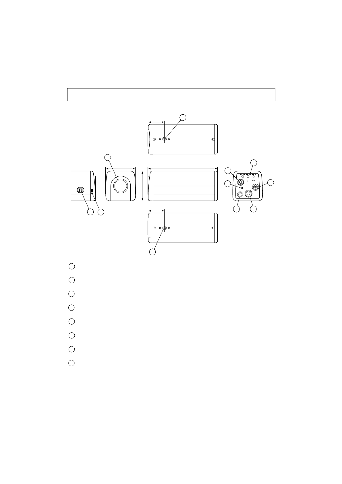
PART NAMES AND FUNCTIONS
33 (1.3)
Lens mount
Mount a CS-mount lens. For C-mount lens or C-mount coupler, use supplied C-mount ring.
Camera mount
For mounting a camera on bracket, tripod, etc. (1/4"-20UNC thread)
Back focus dial
Refer to "HOW TO USE" on page 4 for details.
IRIS terminal
Connect when an automatic iris lens is used.
VIDEO OUT terminal
Connect to a monitor TV, etc. (BNC connector)
S-VIDEO OUT terminal
Connect to a VCR with S-video terminal. (MiniDIN4Pjack)
SC-phase adjustment
Adjustment the SC phase of external synchronous control.
Camera control switches
[Display button, Shift button, Select button, Data button (up, down)]
Refer to "CAMERA CONTROLS (OSD)' on page 6.
All dimensions in mm (inch)
2
4
1
60 (2.4)
60 (2.4)
33 (1.3)
140 (5.5)
3
2
1
2
3
4
5
8
6
7
9
10
5
6
7
8
- 3 -
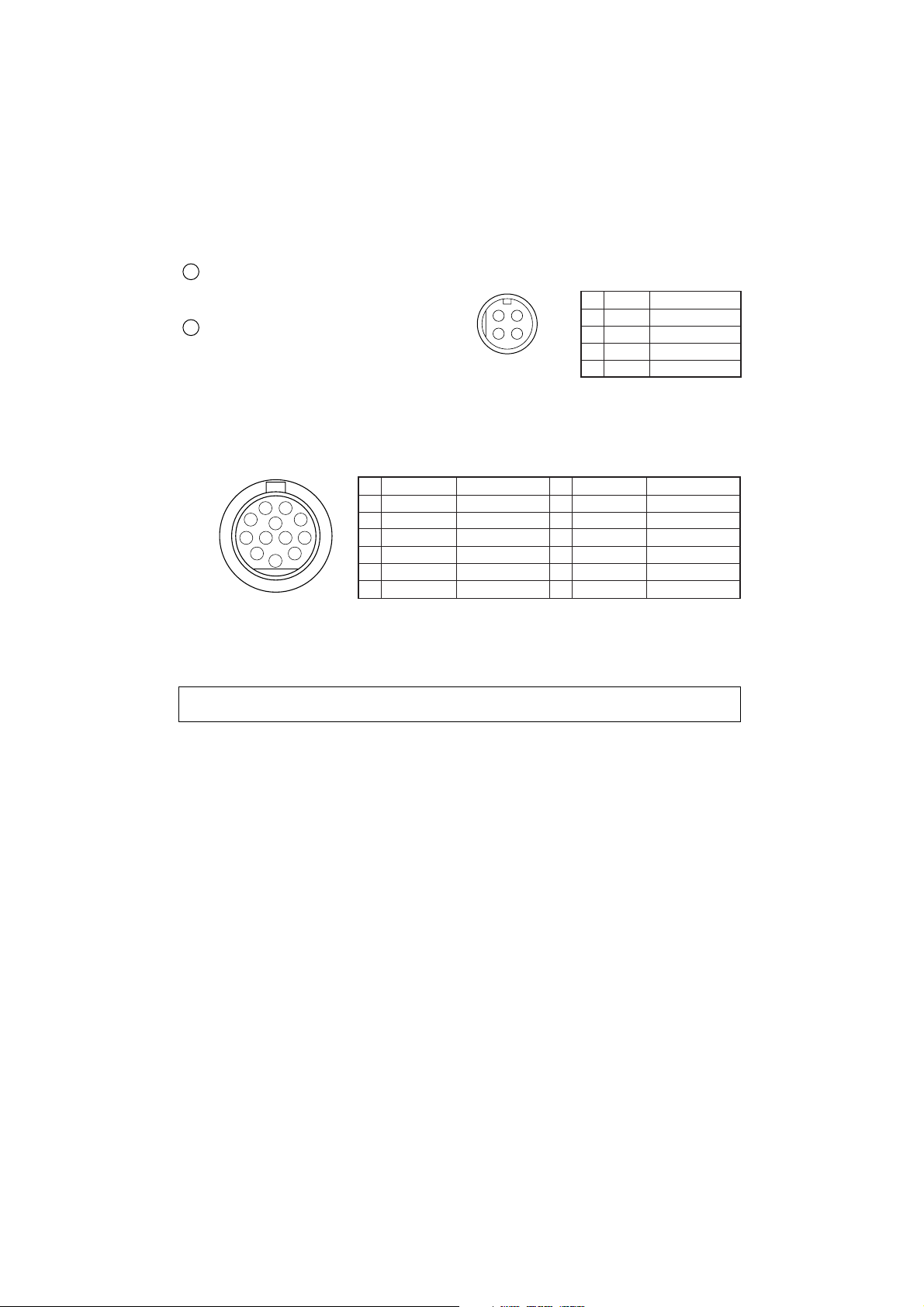
HOW TO CONNECT
Before connection, make sure that power of all units to be connected are OFF and cords are unplugged.
1. Mount a lens onto the camera. Refer to "HOW TO USE" on page 4 for usable lens.
2. Connect video terminal of the camera and the video input terminal of a monitor TV, etc. with a
75Ω coaxial cable.
3. Connect the 4P-connector cable for 12VDC power and the 12P-connector, which
accommodates 12VDC input, external sync input and Y/C output. (You may procure separately
the cable assemblies by using supplied connectors or purchase them from ELMO as an option)
Caution: Installation should be made by a qualified service personnel and should conform to
all local codes.
Lens, coaxial cable for video signal and power supply are not supplied with a
camera.
Don't connect the S-VIDEO terminal and "Y/C OUT" of 12P terminal at the same
time.
Do not supply 12VDC from 4P-connector and 12P-connector simultaneously.
4P terminal
Connect this to the DC 12V power supply.
(Refer to Fig.1)
12P terminal
This 12-pin connector has following inputs
and an output.
· DC 12V input (Do not use DC 12V from
4P terminal simultaneously.)
· External sync. input.
· S-VIDEO (Y/C) output. (Refer to Fig.2)
9
Soldering side
Connector Pin Assignments
Soldering side
Connector Pin Assignments
(Fig. 2)
Supplied plug
(HIROSE HR10A-7P-4S)
Supplied plug
(HIROSE HR10A-10P-12S)
(Fig. 1)
10
3
2
4
1
10
11 12
5
9
8
7
6
Name
1
GND
2
12V
3
GND
4
Y
5
NC
6
NC
1
4
2
3
1
2
3
4
Role of Signal
GND
DC IN 12V
GND
Y OUT
No connection
No connection
7
EXT. SYNC
8
9
10
11
12
Name
GND
C
GND
12V
GND
Name
12V
12V
GND
GND
Role of Signal
DC IN 12V
DC IN 12V
GND
GND
Role of Signal
EXT. SYNC IN
GND
C OUT
GND
DC IN 12V
GND
- 4 -
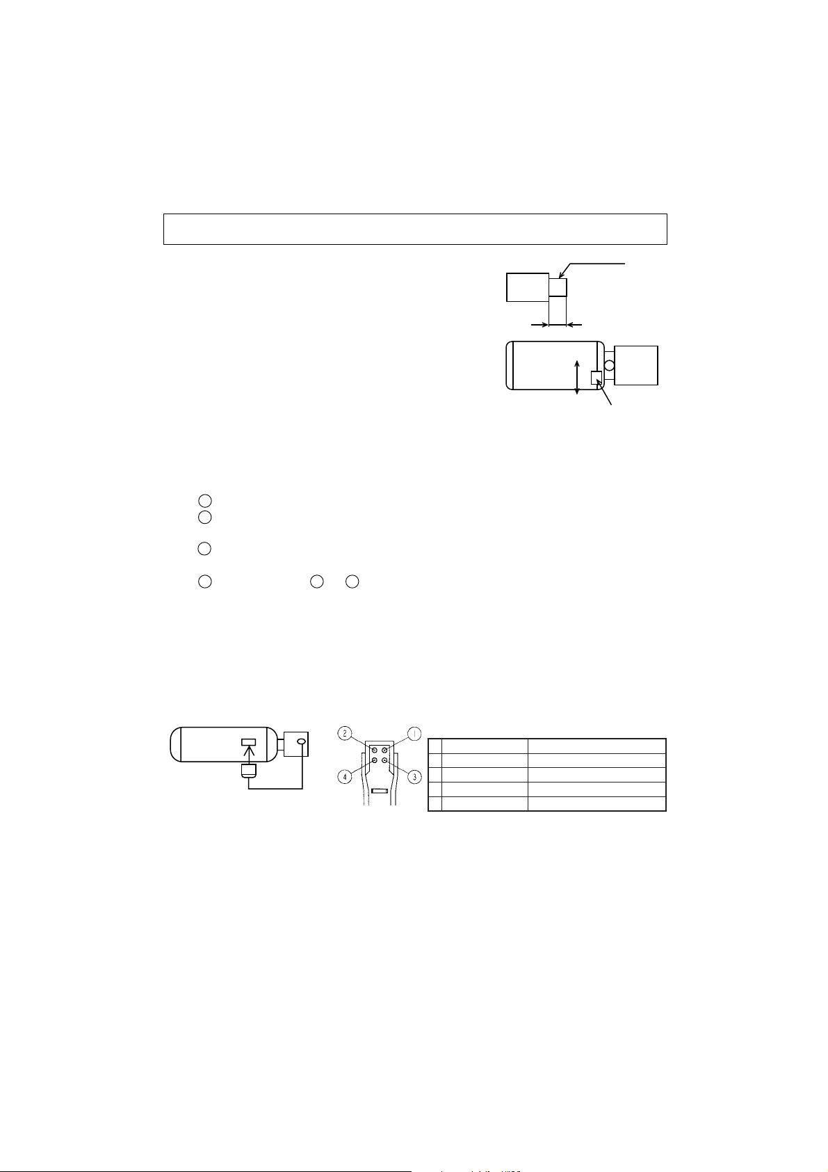
HOW TO USE
1. Adjust the iris and focus of the lens so that optimum image
may be obtained.
* Usable lenses
CS-mount lenses, whose length "L" (in the illustration)
from the bearing surface of the mount is 5mm or less if
protruded, should be used.
*For C-mount lenses or C-mount coupler, use a supplied
5mm ring between the lens and camera.
Adjust the back-focus only when necessary.
Note: Adjustment of the lens back-focus.
The camera is set at the factory for standard back focus position. Some zoom lenses may
require slight adjustment to the back focus. In those cases, follow these instructions.
Adjust the lens back-focus by turning the back focus dial in either direction as per the
illustration, referring to the following instructions.
Place an object at any fixed distance and set the focus ring of the zoom lens accordingly.
Set the zoom lens to full TELE position and obtain the best focus position by turning the
focus ring on the zoom lens.
Set the zoom lens to full WIDE position and obtain the best focus position by turning the
back focus dial located on the side of the camera.
Lens
l
Repeat procedures and until focus remains constant throughout the zooming range.
Note: When the weight of the lens is more than 1kg (2.2lbs), the camera should be supported by
the lens rather than relying on camera mounting screw.
* Using an auto iris lens
When a DC driven type auto iris lens is used, set the IRIS address (OSD) at DC and connect the
plug of the lens to the IRIS terminal at the side of the camera.
When a video feedback type auto iris lens is used, set the IRIS address (OSD) at VIDEO and
connect the plug from the lens to the IRIS terminal at the side of the camera. (Refer to the lens
manual for the level adjustment.)
* When a video feedback type auto iris lens (peak/average selectable type) is used at peak mode,
the BLC feature of the camera may not function correctly. In such a case, change the mode to
average.
* When using at auto iris lens, set the shutter mode at OFF (OSD).
* The shutter mode at AUTO (OSD) may increase smears on monitors, which is caused by
characteristics of CCD and that is not fault of the camera.
Plug for IRIS terminal
(CHUOMUSEN E4-191J-150) Soldering side
CS-mount
5mm or less
L
1
2
3
324
IRIS terminal Pin Assignments
DC setting (OSD)
Control -
1
Control +
2
Drive +
3
Drive - (GND)
4
Camera
VIDEO setting (OSD)
+9V iris power (50mA Max.)
0.7Vp-p auto iris video signal
Lens
Back focus dia
GND
GND

- 5 -
(a) Internal Synchronous Control
(b) External Synchronous Control by VBS
The internal sync. mode automatically changes to the external sync. mode when the VBS signal
from an external control unit is supplied to 'EXT. SYNC' of 12P terminal on the back of the
camera.
*Required signal for the external synchronization
VBS (75Ω unbalanced) SYNC 0.3Vp-p ± 0.1Vp-p
BURST 0.3Vp-p ± 0.1Vp-p
Limits of frequency deviation within ± 50ppm against the NTSC standard system.
(Horizontal frequency approx. 15.7335kHz ~ 15.7350kHz)
In case of synchronous use of more than two cameras. Horizontal phase and Sub-carrier (SC)
phase can be adjusted to match the images from respective cameras, if necessary.
CAMERA
INT./EXT. SYNCHRONOUS CONTROL
Monitor TV
To DC 12V power supply
Monitor TV
CAMERA
C-SYNC./C-VIDEO
PG/CAMERA
To DC 12V power supply

- 6 -
CAMERA CONTROLS (OSD
)
To set up the camera, use the SETUP screen displayed on your monitor TV.
1. SETUP OF EACH FUNCTION
UP
1. Press the DISPLAY button on the back side of the camera to display the SETUP screen on
your monitor TV.
2. Use the SHIFT button to choose the mode.
3. Use the SELECT button to choose the address.
4. Use the DATA (UP and DOWN) buttons to choose the data.
5. When the setup is completed, move the cursor to END by pressing the SHIFT button.
Choosing MEMORY and pressing DISPLAY button stores the latest settings to the
memory. Choosing CLEAR and pressing DISPLAY button clears the settings and the
camera returns to the factory settings.
6. When you have made changes to the setting, make sure to move the cursor to END and
press the DISPLAY button to clear the setup screen. At that point, the settings are stored to
the camera. Remember that turning off the unit while the setup screen is displayed will not
store the settings and it returns to the previously-stored settings.
DISPLAY SHIFT
DATA
SELECT
(Back side of the camera)
DOWN

- 7 -
2. CAMERA CHARACTER (CHR)
(Factory setting is OFF.)
(1) ON:
You can display up to 7 characters.
The blinking character is the one currently
selected. Each time you press the DATA
button, the character changes in the order listed
in the following table.
Press the DISPLAY button to move the
blinking mode to the next character, and you
can select it by pressing the DATA buttons.
When the OSD display disappears, characters
are displayed in white at the bottom of the
screen.
(2) OFF:
Characters do not appear.
Characters that can be used

- 8 -
3. WHITE BALANCE (WB)
Allows you to make the white balance adjustment automatically or manually, for a color
temperature range 2900K - 8000K. (Factory setting is AUTO.)
(1) AUTO:
Sets the automatic color temperature tracking mode. White balance may not be adjusted if
the lighting conditions are bad.
(2) MANU:
Sets the manual adjustment mode. This mode is effective for imaging with low variations
in color temperature.
(3) PUSH:
Use when you want to adjust the white balance with one-push operation. This allows you
to make more accurate adjustment than the AUTO mode. This mode is effective for
imaging with low variations in color temperature. Pressing the UP button after selecting
PUSH sets the data.
4. AGC (AGC)
When the sensitivity selection switch at the left side of the camera is ON, the following
adjustments are enabled: (Factory setting is ON.)
(1) ON:
Allows you to specify the maximum gain for
AGC.
Choices include 6dB, 12dB, and 18dB.
(Factory setting is 12dB.)
(2) OFF:
Allows you to adjust the camera gain manually.

5. SHUTTER (SHUT)
Select either manual or automatic selection of the electronic shutter. (Factory setting is OFF.)
(1) OFF:
Factory setting (1/60 sec)
(2) AUTO:
Automatically selects the electronic shutter.
(3) HS1:
You can select among the 8 shutter speeds.
Choose one from:
1/100 1/125 1/250 1/500 1/1,000 1/2,000
1/4,000 and 1/10,000 sec.
(4) HS2:
You can specify the shutter speed from 1H to
262H in 1H increments.
(approx. 1/10,000 sec - 1/60 sec)
Choosing the AUTO mode or the high speed shutter
mode under the illumination of a flurescent light
may cause flicker or change in the white balance.
In this case, set SHUT to the OFF mode and use
the auto iris lens.
(5) LS1:
In the slower-side shutter, you can specify the
speed from 2F (field) - 510F (field) in 2F
increments.
NTSC: (2/60 sec - 510/60 sec)
(6) AUTO2:
Automatically changes the slower-side shutter
depending on the quantity of light. You can
also choose the upper-limit speed from 2F, 4F,
8F, 16F, 32F and 64F.
* If you choose 1/100, there will be no flicker
even when the object becomes brighter.
* In case the accumulated time becomes long
in the slower-side shutter mode while
shooting a fast-moving object, the picture
may viewed with after-image.
FREEZE PICTURE MODE
You can enter the freeze picture (field) mode by pressing the DOWN button of the data
button while the SHUTTER mode is OFF.
To return to the original live picture, press the DOWN button again.
- 9 -

- 10 -
6. BACKLIGHT CORRECTION (BLC)
Backlight correction prevents the object from becoming dark when there is a strong light (such
as spotlight) in the background. (Factory setting is OFF.)
(1) OFF:
Factory setting
(2) AUTO:
Depending on the position of the object in the
screen, Area 0, Area 1, or Area 2 will
automatically be selected.
(3) ON:
Allows you to manually select from Area 0,
Area 1, or Area 2.
Metering area
Metering area
Area 0 Area 1 Area 2
Metering area

- 11 -
7. SYNC (SYNC)
(Factory setting is H.PH)
(1) H.PH:
Allows you to make horizontal phase
adjustment during external sync. Use the dualtrace oscilloscope to observe the waveform of
external sync signal and of the picture output
signal from the camera and then use the DATA
(UP or DOWN) buttons to make an adjustment
so that the phases will match.
(2) SC.PH:
Allows you to make SC phase adjustment
during external sync. Choose either 0, 90, 180
or 270 and make fine-adjustment in the SCPHASE volume on the back side. Using the
vector scope for the phase adjustment enhances
the accuracy.
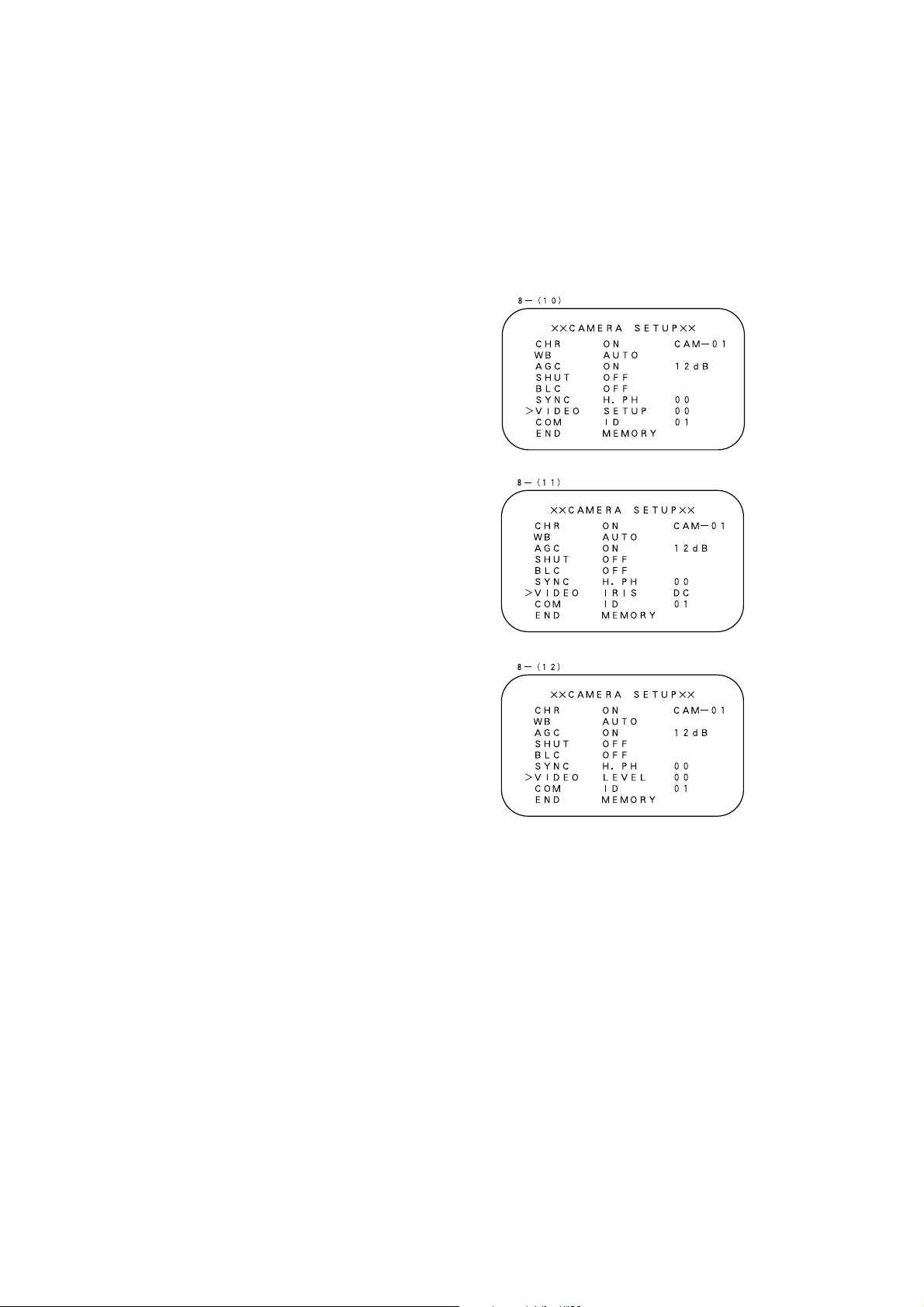
8. VIDEO ADJUSTMENT (VIDEO)
(Factory setting is 0.)
When you set the white balance to the AUTO or the PUSH mode, the following functions are
enabled:
(1) AWB R:
Select UP to increase the red in the whole
image.
(2) AWB B:
Select UP to increase the blue in the whole
image.
When you set the white balance to MANU mode,
the following functions are enabled:
(3) MWB R:
Select UP to increase the red in the whole
image.
(4) MWB B:
Select UP to increase the blue in the whole
image.
- 12 -
The following functions work regardless of the
white balance mode:
(5) R GAIN:
Adjusts the depth of red.
(6) B GAIN:
Adjusts the depth of blue.
(7) R.PH:
Adjusts the tone of red.
(8) B.PH:
Adjusts the tone of blue.
(9) VH.AP:
Adjusts the aperture level. Select UP to
sharpen the picture.
(10) SET UP:
Adjusts the pedestal level (black level) of the
picture. Select UP to brighten the picture.
(11) IRIS:
When using the DC type auto iris lens, set
the IRIS address to DC and connect the lens
plug to the IRIS terminal on the right side of
the camera. When using the video feedback
type auto iris lens, set the IRIS address to
VIDEO and connect the lens plug to the IRIS
terminal on the right side of the camera.
(12) LEVEL:
Adjusts brightness of the DC type auto iris
lens when the IRIS mode is set to DC.
Adjustments in LEVEL are disabled when
you set the IRIS address to VIDEO.
Note: When using the auto iris lens in the VIDEO
mode, the backlight compensation (BLC)
may not function properly.

- 13 -
9. COMMUNICATION (COM)
Don't use this function in this camera model.
10. END (END)
To finish the setup operations, press SHIFT and enter into the END mode.
(1) MEMORY:
Saves the settings and disappers from the setup screen.
(2) CLEAR:
Resets all settings to the factory values and disappers from the setup screen. (You cannot,
however, clear the ID number and the terminal resistance status.)

- 14 -
Model HC7501
Power source DC12V (DC11V~16V)
Power consumption Approx.4.2W
Pick-up device 1/2" Color interline-transfer CCD
Effective picture element 768 (H) x 494 (V)
Scanning area 6.45mm (H) x 4.84mm (V)
Scanning system 2:1 interlaced
Scanning frequency 15.734kHz (H), 59.94Hz (V)
Sync. system Internal/External
Resolution 480 TV lines (Horizontal) 350 TV lines (Vertical)
S/N ratio More than 50dB
Recommended illumination 120 lx (F1.4 under incandescent lamp)
Minimum illumination 2.0 lx (F1.4 under incandescent lamp, AGC at 18dB)
0.12 lx (F1.4 under incandescent lamp, sens up at 16F)
AGC Built-in (Factory-set at ON, 12dB)
White balance AUTO/Manual/Push-set (Factory-set at ON, AUTO)
BLC (Backlight Compensation) Built-in (Factory-set at OFF)
AES (Automatic Electronic Shutter) Built-in 1/60 ~ 1/10,000 sec. (Factory-set at OFF)
Electronic shutter Built-in
1/60 1/100 1/250 1/500 1/1,000 1/2,000 1/4,000 1/10,000 sec.
Frame accumulation Built-in 64 frame in Auto mode
Menu (On Screen Display) AGC, White balance, BLC, AES, Electronic shutter, SYNC. Adjust,
Video adjust, Character
Video Output VBS 1.0 V(p-p), 75Ω, NTSC, compatible
Y/C Output Y: 1.0 V(p-p), 75Ω
C: 0.286 V(p-p), 75Ω
S-VIDEO terminal or 12P terminal
External sync. Input VBS 1.0 V(p-p), 75Ω 12P terminal
Auto-iris terminal 4P (DC/Video)
Power terminal 4P terminal or 12P terminal
Lens mount CS-mount/C-mount with 5mm ring
Ambient temperature -10°C ~ +50°C (14°F~122°F)
Ambient humidity 30% ~ 90%
Dimensions 60 (W) x 60 (H) x 140 (D)mm (2.4 x 2.4 x 5.5 inches)
Weight 410grm (0.9lbs)
SPECIFICATIONS
Note: Weight and dimensions are approximate.
Design and specifications are subject to change without prior notice.

- 15 -
PRECAUTIONS FOR USE AND INSTALLATION
* Never aim the camera at the sun.
Never aim or point the camera at the sun even if you
are not shooting.
* Do not shoot intense light.
Strong light such as a spot light on the image plane will
cause blooming or smear. When strong light comes
into the image plane, vertical stripes may appear on it.
However, this does not mean that the camera is defect.
* Take precautions when handling a camera.
Do not drop your camera, or give it a strong shook
or vibration. This may cause camera to malfunction.
* Do not touch internal parts.
Be sure not to touch the internal parts. This may
cause to electrical shock.
* Do not let the camera get wet.
Install the camera at the place where it will not get wet.
Should it gets wet, turn off the power immediately
and contact your dealer.
* Install your camera where no video noise appears.
When camera cables have been laid near electric wires
or television receivers, a noise may interfere the image.
If noise occurs, relocate cables or reinstall equipment.
* Check the ambient temperature and humidity.
Avoid using camera in areas where temperature is
consistently hotter or colder than the specified range
(See Specifications chart below) or poor image
quality or damaged parts may occur. Precautions
should also be taken to avoid areas of high humidity.
* Should you notice any trouble.
If any trouble occurs while you are using the
camera, turn off the camera and contact your dealer.
Failure to do so may cause damage to the camera.
* The socket-outlet should be installed near the
equipment and should be easily accessible.
* Do not place this video product on an unstable cart,
stand, tripod, bracket, or table. The video product may
fall, causing serious injury to a child or adult, and
serious damage to the appliance. Use only with stand,
tripod, bracket, or table recommended by the
manufacturer, or sold with the video product. Any
mounting of the appliance should follow the
manufacturer's instructions, and should use a mounting
accessory recommended by the manufacturer.
* This video product should be operated only from the
type of power source indicated on the marking label.
If you are not sure of the type of power supply to
your location, consult your appliance dealer or local
power company.
* Power-supply cords should be routed so that they
are not likely to be walked on or pinched by items
placed upon or against them, paying particular
attention to cords at plugs, screws, and the point
where they exit from the appliance.
* Do not overload power supply and extension cords,
as this can result in a risk of fire or electric shock.
* Never push objects of any kind into this video
product through openings as they may touch
dangerous voltage points or short-out parts that
could result in a fire or electrical shock. Never spill
liquid of kind on the video product.
* When replacement parts are required, be sure the
service technician has used replacement parts
specified by the manufacturer or that have the same
characteristics as the original parts. Unauthorized
substitutions may result in fire, electric shock or
other hazards.
* Upon completion of any service or repairs to this
video product ask the service technician to perform
safety checks to determine that video product is in
proper operating condition.
ELMO CO., LTD.
OVERSEAS SUBSIDIARY COMPANIES
ELMO Mfg. Corp.
1478 Old Country Road,
Plainview, NY 11803-5034
U.S.A.
516-501-1400
Tel.
Fax. 516-501-0429
E-mail:elmo@elmousa.com
Web:http://www.elmousa.com/
6X1NHRB02 Printed in CHINA
6-14, Meizen-cho, Mizuho-ku,
Nagoya, 467-8567 Japan
ELMO Canada Mfg. Corp.
44 West Drive, Brampton,
Ontario, L6T 3T6,
Canada
905-453-7880
Tel.
Fax. 905-453-2391
E-mail:info@elmocanada.com
Web:http://www.elmocanada.com/
ELMO (Europe) G.m.b.H.
Neanderstr. 18
40233 Dusseldorf,
Germany
0211-376051-53
Tel.
Fax. 0211-376630
E-mail:elmoeurope@AOL.com
Web:http://www.elmo.de/
 Loading...