

Page 1
Elmo Motion Control
CANopen DSP 305
Implementation Guide
Version 1.1- April 2006
Page 2

Important Notice
This guide is delivered subject to the following conditions and restrictions:
This guide contains proprietary information belonging to Elmo Motion Control Ltd.
Such information is supplied solely for the purpose of assisting users of
servo drives in implementing CANopen networking.
The text and graphics included in this manual are for the purpose of illustration and
reference only. The specifications on which they are based are subject to change
without notice.
Information in this document is subject to change without notice. Corporate and
individual names and data used in examples herein are fictitious unless otherwise
noted.
SimplIQ
Doc. No. MAN-
CAN305IG
Copyright 2006
Elmo Motion Control Ltd.
All rights reserved.
Revision History
Ver. 1.1 Apr. 2006 COB-ID Changes (MAN-CAN305IG)
Ver. 1.0 Nov. 2004 Initial Release (MAN-CAN305IG)
Elmo Motion Control Ltd.
64 Gisin St., P.O. Box 463
Petach Tikva 49103
Tel: +972 (3) 929-2300
Fax: +972 (3) 929-2322
Elmo Motion Control Inc.
1 Park Drive, Suite 12
Westford, MA 01886
USA
Tel: +1 (978) 399-0034
Fax: +1 (978) 399-0035
Elmo Motion Control GmbH
Steinbeisstrasse 41
D-78056, Villingen-Schwenningen
Germany
Tel: +49 (07720) 8577-60
Fax: +49 (07720) 8577-70
www.elmomc.com
Page 3

CANopen DSP 305 Implementation Guide
MAN-CAN305IG (Ver. 1.1)
iii
Contents
1 Introduction ................................................................................................................ 1-1
1.1 Objectives of LSS ......................................................................................................... 1-1
1.2 Abbreviations and Terms........................................................................................... 1-1
1.3 LSS Hardware Restrictions (LSS Address) ............................................................... 1-2
1.4 LSS Operating Restrictions......................................................................................... 1-2
1.5 Elmo Documentation .................................................................................................. 1-3
2 LSS Modes................................................................................................................... 2-1
2.1 Configuration and the Operation Modes................................................................. 2-1
3 LSS Services ................................................................................................................ 3-1
3.1 LSS Master-Slave Synchronization & Protocol......................................................... 3-1
3.2 Switch Mode Services ................................................................................................. 3-2
3.2.1 Switch Mode Global.......................................................................................... 3-2
3.2.2 Switch Mode Selective...................................................................................... 3-3
3.3 Configuration Services................................................................................................ 3-4
3.3.1 Configuration Node-ID .................................................................................... 3-4
3.3.2 Configuration Bit Timing Parameters............................................................. 3-5
3.3.3 Activate Bit Timing Parameters....................................................................... 3-6
3.3.4 Store Configuration Parameters ...................................................................... 3-7
3.4 Inquiry Services........................................................................................................... 3-8
3.4.1 Inquire LSS Address ......................................................................................... 3-8
Inquire Vendor-ID Protocol............................................................................. 3-8
Inquire Product-Code Protocol........................................................................ 3-8
Inquire Revision-Number Protocol................................................................. 3-9
Inquire Serial-Number Protocol...................................................................... 3-9
3.4.2 Inquire Node-ID................................................................................................ 3-9
Inquire Node-ID Protocol ...............................................................................3-9
3.5 Identification Services............................................................................................... 3-10
3.5.1 LSS Identify Remote Slaves............................................................................ 3-10
Inquire Node-ID Protocol .............................................................................3-10
3.5.2 LSS Identify Slave Protocol............................................................................ 3-11
3.5.3 Example............................................................................................................ 3-12
4 Implementation Rules ............................................................................................... 4-1
Page 4

CANopen DSP 305 Implementation Guide
MAN-CAN305IG (Ver. 1.1)
1-1
1 Introduction
This document describes the objects and operational modes of the Elmo DSP-based
motion controller implementation of the CiA DSP 305 protocol. The Elmo Harmonica
digital servo drive (part of the
examples are shown in this document.
Notes:
The DSP in CiA DSP 305 stands for Draft Standard Proposal.
The DSP in Elmo DSP-based motion controller stands for Digital Signal Processor.
With the DSP 305 Layer Setting Services and protocol, unconfigured devices in a
network can be identified by their unique manufacturer, product, serial and revision
number. After identification Bit Rate and Node ID can be configured for each device.
SimplIQ family of digital servo drives ) is used whenever
1.1 Objectives of LSS
CiA DSP 305 CANopen Layer Setting Service and Protocol (LSS) services and protocols
were created to enable the following parameters to be read and changed through the
network:
The CANopen Node ID
The CAN baud rate
The LSS address
This increases the “plug–and-play” capabilities of devices on CANopen networks as preconfiguration of the network is less restrictive.
The LSS Master is responsible for configuring these parameters on one or more LSS
Slaves on a CANopen network.
1.2 Abbreviations and Terms
The following terms are used in this document:
COB (Communication Object): A unit of transportation in a CAN network.
Data must be send across a CAN network inside a COB. A COB can
contain at most 8 bytes of data.
COB-ID Each COB is uniquely indentified in a CAN network by a number called
the COB Identifier (COB-ID). The COB-ID determines the priority of the
COB for the MAX sub-layer.
Elmo Composer An Elmo software application used for controller setup, application
downloading and monitoring.
Hexadecimal Numbers marked with either “h” (such as 1000h) or “0x” (such as
0x1000) refer to a hexadecimal value. Objects and numbers may appear
in either form in different CAN documents
Page 5

CANopen DSP 305 Implementation Guide
MAN-CAN305IG (Ver. 1.1)
1-2
LMT (Layer Management): Functions to inquire and change the settings of
certain parameters of the local layers on a CAL module.
LSS (Layer Setting Services): Functions to inquire and change the settings of
certain parameters of the local layers on a CANopen network. An LSS
Master can change the following parameters of LSS Slaves:
Node ID
Timing parameters of the physical layer (Baud Rate)
LSS address
The LSS Slave can be configured for a CANopen network without using
any hardware based devices such as DIP-switches.
LSS Master The device that configures other modules via a CANopen Network.
There may be only one LSS Master in a network.
LSS Slave The device that is configured by the LSS Master via a CANopen Network
is called the LSS Slave.
MAC (Medium Access Control): One of the sub-layers of the Data Link Layer
in the CAN Reference Model that controls who gets access to the
medium to send a message.
NMT (Network Management): One of the service elements of the application
layer in the CAN Reference Model. The NMT serves to configure,
initialize, and handle errors in a CAN network.
1.3 LSS Hardware Restrictions (LSS Address)
All LSS Slaves must support valid Object Dictionary entries for Identity object [1018h]
which has 32 bits for each part of the LSS Address:
Vendor-ID (numerical number)
Product-Code (numerical number)
Revision-Number (major an minor revision as numerical number)
Serial-Number (numerical number)
A Product-Code, Revision-Number and a Serial-Number are assigned by the device
supplier. The LSS address which must be absolutely unique. No other LSS slave may
have the same LSS address.
1.4 LSS Operating Restrictions
To function properly the following restrictions apply:
All devices on a CANopen network must support LSS.
There can be only one LSS Master.
All nodes are required to start-up with the same initial baud rate.
LSS communication can take place during any NMT state such as “stopped”
or "pre-operational".
Page 6
CANopen DSP 305 Implementation Guide
MAN-CAN305IG (Ver. 1.1)
1-3
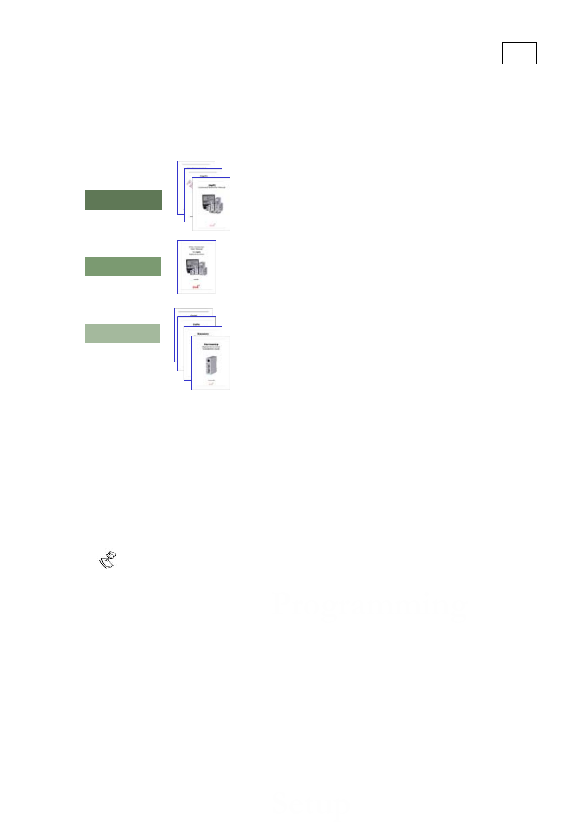
1.5 Elmo Documentation
This manual – included in the Elmo CANopen Implementation Guide – is part of the Elmo
SimplIQ digital servo drive documentation set, as outlined in the following diagram:
In addition to this document, the
SimplIQ documentation set includes:
The Harmonica, Bassoon, Cello and Cornet Installation Guides, which provides full
instructions for installing
SimplIQ digital servo drives.
The Composer User Manual, which includes explanations of all the software tools that
are a part of Elmo’s Composer software environment.
The
SimplIQ Software Manual, which describes the comprehensive software used with
the
SimplIQ line of digital servo drives.
The CANopen Implementation Guide, which explains how to implement CANopen DS
301-based communication (including DSP 402) with a
SimplIQ digital servo drive.
Note:
SimplIQ drives are fully compliant with CiA’s DSP305 protocol for Layer Setting
Service (LSS).
Page 7

CANopen DSP 305 Implementation Guide
MAN-CAN305IG (Ver. 1.1)
2-1
2 LSS Modes
Devices that communicate with the LSS protocol can be in one of two modes,
‘Configuration Mode’ and ‘Operation Mode’. Any device on the network that is not in
‘Configuration Mode’ is in ‘Operation Mode’. In ‘Configuration Mode’ all LSS services
are available. In ‘Operation Mode’ only the switch mode services are available.
Switching the mode of a device to ‘Configuration Mode’ must be explicitly initiated by
the LSS Master. Mode switching is independent of the NMT state. With the exception of
the LSS service ‘Configure Node-ID’ the NMT state of the device is not affected by LSS
services.
If the Node-ID of the LSS Slave is changed with the LSS service ‘Configure Node-ID’, and
the slave is switched back from ‘Configuration Mode’ to ‘Operation Mode’, a power-on
like reset must be performed by the LSS slave; this affects the NMT state. For this reason
the LSS-Master must reside on the same device that holds the NMT-Master.
2.1 Configuration and the Operation Modes
An LSS Slave can be in one of two LSS modes:
Configuration Mode
When an LSS Slave is in this mode, it actively listens for and processes
configuration commands from the LSS Master.
Some configuration commands configure only one LSS Slave at the time
(for example, to change of CANopen node ID)
Some configuration commands configure multiple or all LSS Slave nodes (for
example, to change the baud rate)
Operation Mode
An LSS Slave in this mode ignores the configuration commands from the LSS
Master.
Page 8

CANopen DSP 305 Implementation Guide
MAN-CAN305IG (Ver. 1.1)
3-1
3 LSS Services
LSS services can be functionally grouped into four categories:
Switch Mode Services provide a way to logically connect the LSS Master
and LSS Slave(s) for configuration purposes. They change the LSS mode
attribute of the LSS Slave (see the Figure
Configuration Services perform the actual task of configuring the layer
parameters of LSS Slave(s). The configuration services are only available
in configuration mode.
Inquiry Services provide a way for the LSS Master to determine layer
parameters. The inquiry services are available only in configuration mode.
Identification Services provide a way for the LSS Master to determine the
presence of a device and to check for devices with invalid Node-ID. The
identification services are available in configuration and operation mode.
3-1).
Configuration Mode
Switch Mode Global
Operation_Mode
parameter with Node
I.D. unchanged
Operation Mode
Switch Mode Global
Operation_Mode
parameter with Node
I.D. unchanged
Switch Mode global
Operation Mode
parameter with NodeID changed.
Switch Mode
selective with
Matching LSSaddress parameter.
Power-on
Reset
Node Diagram
Figure 3-1 LSS Slave Modes and Switching Services
3.1 LSS Master-Slave Synchronization & Protocol
In the LSS Protocol all slaves use the same Communications Object (COB) to send
information to the LSS Master. In order to ensure that only one LSS Slave
communicates with the LSS Master at a time, a switching mechanism, under the
control of the LSS Master is implemented.
A slave can only communicate with the Master after it has been switched into
Configuration Mode by the master. In other words, the Master must first take the
initiative. Furthermore, the Slave only communicates specific information requested
by the Master.
Page 9

CANopen DSP 305 Implementation Guide
MAN-CAN305IG (Ver. 1.1)
3-2
The protocols described below all have the same structure: a specific sequence of
COBs are exchanged between the LSS Master and LSS Slave for a particular LSS
service. Requesting Messages use COB-ID 7E5h while Response Messages use COB-ID
7E4h.
LSS uses Command Specifiers (CS) to identify the commands. CSs from 00 - 03fh are
reserved for use by the LMT. 040h - 07fh are reserved for use by standard LSS
services. Command Specifiers 080h – 0ffh are free for application specific purposes,
but may only be used with one Slave in Configuration Mode at a time.
In the COB data format bytes are numbered from 0 to 7. Bits within a byte are also
numbered from 0 to 7 with bit 0 being the least significant bit (LSB), and 7 the most
significant (MSB).
3.2 Switch Mode Services
Switch Mode Services controls the mode of LSS Slaves. There are two ways to put an
LSS Slave into configuration mode, with Switch Mode Global and with Switch Mode
Selective. Switch Mode Selective switches one LSS Slave between configuration and
operation mode. Switch Mode Global switches all LSS Slaves between configuration and
operation mode.
If the Node-ID of a slave is changed with the LSS ‘Configure Node-ID’ service, a
Switch Mode Global with the operation_mode parameter causes a power-on-like reset
of the LSS Slave to force a change in the slave’s default set-up parameters.
3.2.1 Switch Mode Global
This service is used to switch all LSS Slaves in the network between operation mode
and configuration mode.
COB-ID = 7E5h
012345678
CS mode
04 00 reserved for future use by CiA
Figure 3-2 Switch all Slaves to Operation Mode
COB-ID = 7E5h
012345678
CS mode
04 01 reserved for future use by CiA
Figure 3-3 Switch all Slaves to Configuration Mode
Page 10

CANopen DSP 305 Implementation Guide
MAN-CAN305IG (Ver. 1.1)
3-3
3.2.2 Switch Mode Selective
This service is used to switch a specific LSS Slave device to configuration mode.
COB-ID = 7E5h
012345678
CS
lsb Vendor-ID msb64 reserved for future use by CiA
Figure 3-4 Switch Slaves, from Specific Vendor, to Configuration Mode
COB-ID = 7E5h
012345678
CS
lsb Product-Code msb65 reserved for future use by CiA
Figure 3-5 Switch Slave, with Specific Product-Code, to Configuration Mode
COB-ID = 7E5h
012345678
CS
lsb Revision-Number msb66 reserved for future use by CiA
Figure 3-6 Switch Slaves, with Specific Revision-Number, to Configuration Mode
COB-ID = 7E5h
012345678
CS
lsb Serial-Number msb67 reserved for future use by CiA
Figure 3-7 Switch Slaves, with Specific Serial Number to Configuration Mode
To switch to a specific device, all four of the above commands must be sent.
Page 11

CANopen DSP 305 Implementation Guide
MAN-CAN305IG (Ver. 1.1)
3-4
3.3 Configuration Services
Configuration services are available only in configuration mode. Some of the services
are only available to one LSS Slave device.
3.3.1 Configuration Node-ID
This service enables the LSS Master to configure the NMT-address of an LSS Slave.
Only one LSS Slave at a time can be configured with this service. A remote result
message confirms the success or failure of the service.
This service works in Configuration Mode. A change in the Node-ID causes a poweron like reset to the device.
COB-ID = 7E5h
012345678
CS NID
17 ## reserved for future use by CiA
Figure 3-8 Switch the Node-ID of a Slave
NID (Node-ID):
If NID is set to FFh it becomes invalid when switching to operation mode. As a
result, the slave enters the ‘LSS Init State’ autonomously.
COB-ID = 7E4h
012345678
CS
Error
Code
17 ## reserved for future use by CiA
Specific
Error
##
Figure 3-9 Confirm the Node-ID of a Slave
Error Codes:
0: protocol successfully completed
1: Node-ID out of range
2 ... 254: reserved for further use by CiA
255: implementation specific error occured.
Specific Error Codes:
If error_code is 0 … 254, then a specific_error_code will be 0.
If error_code is 255, then a specific_error_code will be:
2: incorrect mode
no other options at this time
Page 12
CANopen DSP 305 Implementation Guide
MAN-CAN305IG (Ver. 1.1)
3-5
3.3.2 Configuration Bit Timing Parameters
The LSS Master’s Configure Bit Timing Parameters service sets new bit timing on an
LSS Slave. The bit timing parameters for different baud rates are specified in the Bit
Timing Parameter Table below. With table_selector value ´0´ the standard CiA bit
timing parameter table is used. The table_index selects the entry (baud rate) in the
selected table (value ‘0’ refers to the highest baud rate).
Table Selector Table: Standard CiA Bit Timing Table:
Table
Selection
0: standard CiA Bit Timing Table
1…127: reserved for further use by CiA
128…255: for use by manufacturer for
specific but timings
Note:
Elmo drives only work with the
standards CiA Bit Timing Table.
Table Index
0
1
2
3
4
5
6
7
8
Baud Rate
1000 kBit
800 kBit
500 kBit
250 kBit
125 kBit
reserved
50 kBit
not supported
not supported
This service can be performed on only one LSS Slave, in configuration mode, at a time.
The service must be followed by an Activate Bit Timing Parameters service. After
executing this service the node may not execute any remote LSS services other than
Configure Bit Timing Parameters, Activate Bit Timing Parameters and Switch Mode.
COB-ID = 7E5h
CS
012345678
19 ## reserved by CiA for future use
Table
Selector
Table
Index
##
Figure 3-10 Select Bit Timing
A remote message confirms the success or failure of the service. In case of a failure, the
reason is given.
COB-ID = 7E4h
012345678
CS
Error
Code
19 ## reserved by CiA for future use
Spe c if ic
Error
##
Figure 3-11 Bit Timing Confirmation Message
Error Codes:
0: protocol successfully completed
1: Node-ID out of range
2...254: reserved for further use by CiA
255: implementation specific error occured.
Specific Error Codes:
If error_code is 0 … 254, then a specific_error_code will be 0.
If error_code is 255, then a specific_error_code will be:
2: incorrect mode
Page 13

CANopen DSP 305 Implementation Guide
MAN-CAN305IG (Ver. 1.1)
3-6
3: out of range
3.3.3 Activate Bit Timing Parameters
The LSS Master's Activate Bit Timing Parameters service activates the bit timing as
defined by the Configure Bit Timing Parameters service.
The switch_delay parameter specifies the length of two delay periods of equal length,
which are necessary to avoid operating the bus with differing bit timing parameters.
Each node performs the actual switch of the bit timing parameters switch_delay
milliseconds after the reception of the command. After performing the switch, a node
does not transmit any messages before the second time ´switch_delay´ has passed.
This service can be performed on all LSS Slaves in ‘Configuration Mode’.
COB-ID = 7E5h
CS
012345678
21 reserved by CiA for future use
lsb msb
Switch
Delay
Figure 3-12 Activate Bit Timing Parameters
switch_delay:
The duration of the two periods of time to wait until the bit timing parameters
switch is performed (first period). This is the length of time before any CAN
message can be transmitted with the new bit timing parameters.
Note:
Nodes may have different processing times for performing the Activate Bit
Timing Parameters command. Messages that are transmitted before this
command may still be in the receive queue of a node. This means that a node may
still transmit CAN messages with the old bit timing due to processing delay.
Therefore switch_delay must be longer than the longest processing time of any
node in the network. After the switch_delay time has passed, every node must
perform the switch during the second switch_delay. Only after the second
switch_delay has passed are all nodes guaranteed to be listening with the new bit
timing parameters. Figure
3-13 shows the durations of the two switch_delays.
Page 14

CANopen DSP 305 Implementation Guide
MAN-CAN305IG (Ver. 1.1)
c
LMT Master
********
d1 d2
t
3-7
LMT Slave 1
LMT Slave 2
p2
c: initiation of command
p1, p2: individual processing delay
d1: duration of first switch_delay period
d2: duration of second switch_delay period
********: node may be transmitting
d1 d2
d1 d2p2
********
t
t
Figure 3-13 Switch_Delay Periods
3.3.4 Store Configuration Parameters
The Store Configured Parameters service is used to store the configured parameters in
non-volatile memory.
COB-ID = 7E5h
CS
12345678
23 reserved by CiA for future use
Figure 3-14 Store Configuration Parameters
A return message confirms the success or failure of the service. The reason is specified
if the effort fails. This service is available for only one LSS Slave in ‘Configuration
Mode’ at a time.
COB-ID = 7E4h
012345678
CS
Error
Code
23 ## reserved by CiA for future use
Spe c if ic
Error
##
Figure 3-15 Confirm Configuration Parameters
Error Codes:
0: protocol successfully completed
1: store configuration is not supported
2: storage media access error
3 ... 254: reserved for further use by CiA
255: implementation specific error occurred.
Specific Error Codes:
If error_code is 0 … 254, then a specific_error_code will be 0.
Page 15

CANopen DSP 305 Implementation Guide
MAN-CAN305IG (Ver. 1.1)
3-8
If error_code is 255, then a specific_error_code will be:
2: incorrect mode
no other options at this time
3.4 Inquiry Services
The inquiry services are available only in configuration mode.
3.4.1 Inquire LSS Address
This service finds the LSS-address of a Slave in configuration mode. Since the LSS
address has four parts (Vendor-ID, Product-Code, Revision-Number and SerialNumber), four inquiries are required.
Only one LSS slave may be in configuration mode when this service is executed. A
return message contains the LSS sub-address of the Slave in configuration mode, or
returns an error message.
Inquire Vendor-ID Protocol
COB-ID = 7E5h
CS
12345678
90 reserved for future use by CiA
Figure 3-16 Inquire Vendor-ID
COB-ID = 7E4h
012345678
CS
90 Vendor-ID reserved for future use by CiA
lsb
msb
Figure 3-17 Confirm Vendor-ID
Inquire Product-Code Protocol
COB-ID = 7E5h
CS
12345678
91 reserved for future use by CiA
Figure 3-18 Inquire Product Code
COB-ID = 7E4h
012345678
CS
91 Product-ID reserved for future use by CiA
lsb
msb
Figure 3-19 Confirm Product Code
Page 16

CANopen DSP 305 Implementation Guide
MAN-CAN305IG (Ver. 1.1)
3-9
Inquire Revision-Number Protocol
COB-ID = 7E5h
CS
12345678
92 reserved for future use by CiA
Figure 3-20 Inquire Revision-Number
COB-ID = 7E4h
012345678
CS
92 Revision-Number reserved for future use by CiA
lsb
msb
Figure 3-21 Confirm Revision-Number
Inquire Serial-Number Protocol
COB-ID = 7E5h
CS
12345678
93 reserved for future use by CiA
Figure 3-22 Inquire Serial-Number
COB-ID = 7E4h
CS
12345678
93 Serial-Number reserved for future use by CiA
lsb
msb
Figure 3-23 Confirm Serial -Number
3.4.2 Inquire Node-ID
This command is used to determine the Node-ID of a LSS Slave in configuration
mode.
Only one LSS slave may be in configuration mode when this command is executed.
The return message is the Node-ID of the LSS Slave.
Inquire Node-ID Protocol
COB-ID = 7E5h
0
CS
12345678
94 reserved for future use by CiA
Figure 3-24 Inquire Node-ID
Page 17

CANopen DSP 305 Implementation Guide
MAN-CAN305IG (Ver. 1.1)
3-10
COB-ID = 7E4h
012345678
CS NID
94 ## reserved for future use by CiA
Figure 3-25 Confirm Node-ID
If the Node-ID was recently changed with a Configure Node-ID command, the
original Node-ID will continue to be returned until the next power on reset. A value of
FFh is returned if the Node-ID is not configured … this is only possible if the slave is
in ‘LSS Init State’.
3.5 Identification Services
This protocol is used to implement the 'LSS Identify Remote Slaves' service.
3.5.1 LSS Identify Remote Slaves
By means of this service, the LSS Master requests all LSS slaves, whose LSS address
meets the LSS_Address_sel to identify themselves by means of the 'LSS Identify Slave'
service.
LSS_Address_sel consists of a fixed Vendor ID and Product Code and a span of
revision and serial numbers. This service goes unconfirmed.
Inquire Node-ID Protocol
COB-ID = 7E5h
012345678
CS
lsb Vendor-ID msb70 reserved for future use by CiA
Figure 3-26 Slave Vendor-ID Inquiry
COB-ID = 7E5h
012345678
CS
lsb Product-Code msb71 reserved for future use by CiA
Figure 3-27 Slave Product-ID Inquiry
COB-ID = 7E5h
012345678
CS
lsb Revision-Number-Low msb72 reserved for future use by CiA
Figure 3-28 Slave Revision Number Inquiry
Page 18

CANopen DSP 305 Implementation Guide
MAN-CAN305IG (Ver. 1.1)
3-11
Revision-Number-Low:
The lower boundary of the requested revision numbers range. The Minor range
must be set to 0000h.
COB-ID = 7E5h
012345678
CS
lsb Revision-Number-High msb73 reserved for future use by CiA
Figure 3-29 Slave Revision Number Inquiry
Revision-Number-High:
The higher boundary of the requested revision numbers range. The Minor range
must be set to FFFFh.
COB-ID = 7E5h
012345678
CS
lsb Serial-Number-Low msb74 reserved for future use by CiA
Figure 3-30 Slave Serial-Number Inquiry
Serial-Number-Low:
The lower boundary of the requested serial numbers range
COB-ID = 7E5h
012345678
CS
lsb Serial-Number-High msb75 reserved for future use by CiA
Figure 3-31 Slave Serial-Number Inquiry
Serial-Number-High:
The higher boundary of the requested serial numbers range
The boundaries are included in the interval. All LSS Slaves with matching Vendor-ID
and Product-Code whose major Revision-Number and Sserial-Numbers lie within the
given ranges, are requested to identify themselves with the LSS Identify Slave service.
3.5.2 LSS Identify Slave Protocol
By means of this command, an LSS Slave indicates that it is a Slave with an LSS
address. This address is within the LSS_Address_sel of an 'LSS Identify Remote Slave'
service (CS: 70 to 75) that was executed prior to this command. The result is
unconfirmed.
Note:
If all six Identification messages are valid for an Elmo drive, the drive responds
with a CS 79 message.
Page 19

CANopen DSP 305 Implementation Guide
MAN-CAN305IG (Ver. 1.1)
3-12
COB-ID = 7E4h
0
CS
12345678
79 reserved for future use by CiA
Figure 3-32 Slave Serial-Number Confirmation
3.5.3 Example
If the Master knows that there are several nodes of the same LSS type that only differ
in their serial number, it can ask the following questions to locate them:
Are there any devices with serial numbers between 1276h and 2468h?
COB-ID = 7E5h
012345678
CS
76 12 0 074 reserved for future use by CiA
COB-ID = 7E5h
012345678
CS
68 24 0 075 reserved for future use by CiA
Figure 3-33 Inquire About Slaves with Serial Numbers between 1276h and 2468h?
All Slaves with Serial-Number between 1276h and 2468h send confirmation:
COB-ID = 7E4h
0
CS
12345678
79 reserved for future use by CiA
Figure 3-34 Confirmation from Slaves with Serial-Numbers between 1276h and 2468h
Page 20

CANopen DSP 305 Implementation Guide
MAN-CAN305IG (Ver. 1.1)
4-1
4 Implementation Rules
When implementing the LSS protocols, the following rules must be followed to
guarantee interoperability:
CAL Layer Management (LMT)
To distinguish between LMT and LSS, all LSS services must use command specifiers
in the 040h – 07fh range.
Invalid COB's
A COB is invalid if it has a COB-ID that is used by the LSS Protocol, but contains
invalid parameter values according to the LSS Protocol. This can be caused by errors
in the data link layer or implementation errors. Invalid COB's must be handled locally
in an implementation specific way. As far as the LSS Protocol is concerned, an invalid
COB must be ignored.
Time-Outs
Since COBs may be ignored, the response of a confirmed LSS service may never arrive.
To resolve this situation, an implementation may, after a certain amount of time,
indicate this to the service user (time-out). A time-out is not a confirm of the LSS
service. A time-out indicates that the service has not completed yet. The application
must deal with this situation. Time-out values are considered to be implementation
specific so it is recommended that the implementation provide facilities to adjust these
time-out values to the requirements of the application.
 Loading...