

Page 1
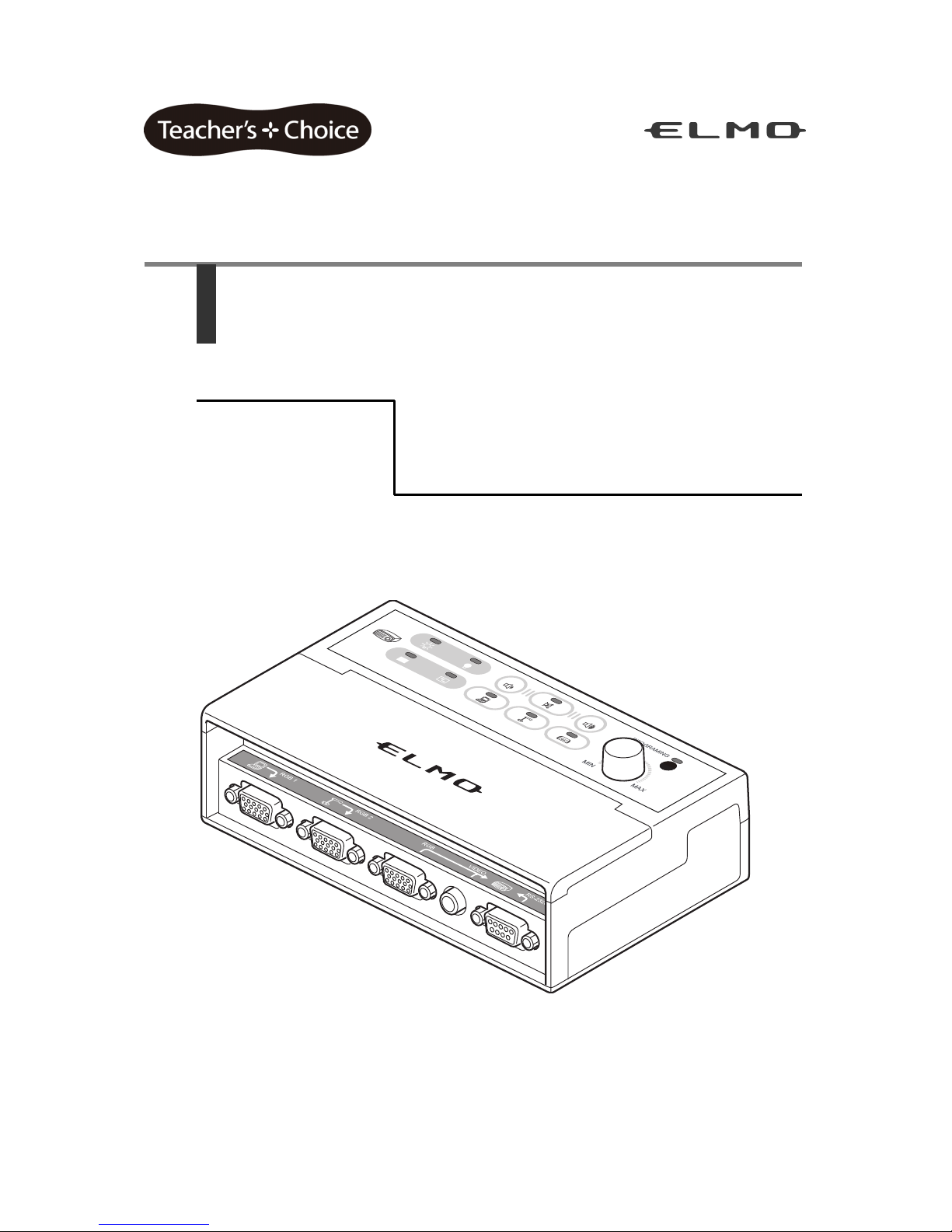
CRC-1
Instruction Manual
Page 2

2
Contents
1. IMPORTANT SAFEGUARDS ........................................................................................... 3
Usage precautions ..................................................................................................... 6
2. List of Contents ............................................................................................................... 8
3. Part Names and Functions ............................................................................................. 9
Exterior ...................................................................................................................... 9
Operation panel ....................................................................................................... 10
Connectors .............................................................................................................. 11
4. Preparations................................................................................................................... 12
Connection diagram ................................................................................................ 12
Installation method................................................................................................... 13
Cable connections ................................................................................................... 14
Controlling with RS-232C ........................................................................................ 16
Infrared learning function ......................................................................................... 18
5. Operating the Unit ......................................................................................................... 21
Operation ................................................................................................................. 21
When there are connectors not connected to peripheral devices ........................... 23
6. Troubleshooting ............................................................................................................ 24
7. Specifications ................................................................................................................ 26
8. Appendix ........................................................................................................................ 28
Selecting a projector to use ..................................................................................... 28
RS-232C command tables....................................................................................... 29
9. Separately Sold Options ............................................................................................... 31
Page 3

3
1. IMPORTANT SAFEGUARDS
■ Read Instructions
All the safety and operating instructions should be read before the appliance is operated.
■ Retain Instructions
The safety and operating instructions should be retained for future reference.
■ Heed Warnings
All warnings on the product and in the operating instructions should be adhered to.
■ Follow Instructions
All operating and use instructions should be followed.
■ Cleaning
Unplug this product from the wall outlet before cleaning. Do not use liquid cleaners or
aerosol cleaners. Use a damp cloth for cleaning.
■ Attachments
Do not use attachments not recommended by the product manufacturer as they may
cause hazards.
■ Water and Moisture
Do not use this product near water - for example, near a bath tub, wash bowl, kitchen sink,
or laundry tub, in a wet basement, or near a swimming pool, and the like.
■ Placement
Do not place this product on an unstable cart, stand, tripod, bracket, or table. The product
may fall, causing serious injury to a child or adult, and serious damage to the product. Use
only with a cart, stand, tripod, bracket, or table recommended by the manufacturer, or sold
with the product. Any mounting of the product should follow the manufacturer's
instructions, and should use a mounting accessory recommended by the manufacturer.
■ Ventilation
Slots and openings in the cabinet are provided for ventilation and to ensure reliable
operation of the product and to protect it from overheating, and these openings must not
be blocked or covered. The openings should never be blocked by placing the product on a
bed, sofa, rug, or other similar surface. This product should not be placed in a built-in
installation such as a bookcase or rack unless proper ventilation is provided or the
manufacturer's instructions have been adhered to.
Page 4

4
■ Power Sources
This product should be operated only from the type of power source indicated on the
marking label. If you are not sure of the type of power supply to your home consult your
appliance dealer or local power company. For products intended to operate from battery
power, or other sources, refer to the operating instructions.
■ Grounding or Polarization
This product may be equipped with either a polarized 2-wire AC line plug (a plug having
one blade wider than the other) or a 3-wire grounding type plug, a plug having a third
(grounding) pin. The 2-wire polarized plug will fit into the power outlet only one way. This is
a safety feature. If you are unable to insert the plug fully into the outlet, try reversing the
plug. If the plug still fails to fit, contact your electrician to replace your obsolete outlet. Do
not defeat the safety purpose of the polarized plug. The 3-wire grounding type plug will fit
into a grounding type power outlet. This is a safety feature. If you are unable to insert the
plug into the outlet, contact your electrician to replace your obsolete outlet. Do not defeat
the safety purpose of the grounding type plug.
■ Power-Cord Protection
Power-supply cords should be routed so that they are not likely to be walked on or pinched
by items placed upon or against them, paying particular attention to cords at plugs,
convenience receptacles, and the point where they exit from the product.
■ Lightning
For added protection for this product during a lightning storm, or when it is left unattended
and unused for long periods of time, unplug it from the wall outlet and disconnect the
antenna or cable system. This will prevent damage to the product due to lightning and
power-line surges.
■ Overloading
Do not overload wall outlets, extension cords, or integral convenience receptacles as this
can result in a risk of fire or electric shock.
■ A product and cart combination should be moved with care.
Quick stops, excessive force, and uneven surfaces may cause
the product and cart combination to overturn.
■ Object and Liquid Entry
Never push objects of any kind into this product through openings as they may touch
dangerous voltage points or short-out parts that could result in a fire or electric shock.
Never spill liquid of any kind on the product.
■ Servicing
Do not attempt to service this product yourself as opening or removing covers may expose
you to dangerous voltage or other hazards. Refer all servicing to qualified service
personnel.
Page 5
5
■ Damage Requiring Service
Unplug this product from the wall outlet and refer servicing to qualified service personnel
under the following conditions:
- When the power-supply cord or plug is damaged.
- If liquid has been spilled, or objects have fallen into the product.
- If the product has been exposed to rain or water.
- If the product does not operate normally by following the operating instructions. Adjust
only those controls that are covered by the operating instructions as an improper
adjustment of other controls may result in damage and will often require extensive
work by a qualified technician to restore the product to its normal operation.
- If the product has been dropped or damaged in any way.
-
When the product exhibits a distinct change in performance - this indicates a need for service.
■ Replacement Parts
When replacement parts are required, be sure the service technician has used
replacement parts specified by the manufacturer or have the same characteristics as the
original part. Unauthorized substitutions may result in fire, electric shock or other hazards.
■ Safety Check
Upon completion of any service or repairs to this product, ask the service technician to
perform safety checks to determine that the product is in proper operating condition.
■ Heat
The product should be situated away from heat sources such as radiators, heat registers,
stoves, or other products (including amplifiers) that produce heat.
SA 1965
The lightning flash with arrowhead symbol, within an equilateral triangle, is
intended to alert the user to the presence of uninsulated "dangerous voltage"
within the product's enclosure that may be of sufficient magnitude to constitute a
risk of electric shock to persons. This marking is located at the bottom of product.
SA 1966
The exclamation point within an equilateral triangle is intended to alert the user to
the presence of important operating and maintenance (servicing) instructions in
the literature accompanying the product.
WARNING:
TO REDUCE THE RISK OF FIRE OR ELECTRIC SHOCK, DO NOT EXPOSE
THIS PRODUCT TO RAIN OR MOISTURE.
Page 6

6
Usage precautions
• Read the Instruction Manual carefully before using this product.
• A power cord is supplied that is suitable for the country of sale.
• The supplied power cord and AC Adapter is for this device only. Do not use them with
other devices. Also, do not use other power cords or AC Adapters.
• Do not store in a location exposed to direct sunlight or frequent vibration.
The operating environment conditions are as follows.
Temperature: 0°C to 40°C (32°F - 104°F) Humidity: 30% to 85% (no condensation)
• When cleaning the unit, wipe it with a soft, dry cloth.
Do not use any volatile solvents such as thinner or benzene.
• Observe the following to prevent the unit from falling or overturning.
- Fix the unit with screws to prevent it from falling or overturning.
- Install and wire the unit in such a way that the AC Adapter cord and video cable will
not be pulled during use.
• If this product is used for a long time beyond the warranty period, its performance or
quality may deteriorate as the parts approach the end of their service lives. We can
replace parts for a fee, so contact the dealer where you purchased the product, or our
nearest branch office or sales office.
Page 7

7
■ FCC Notice
This equipment has been tested and found to comply with the limits for a class B digital
device, pursuant to part 15 of the FCC Rules. These limits are designed to provide against
harmful interference in a residential installation. This equipment generates, uses, and can
radiate radio frequency energy and, if not installed and used in accordance with the
instructions, may cause harmful interference to radio or television reception.
However, there is no guarantee that interference will not occur in a particular installation. If
this equipment does cause interference radio and television reception, which can be
determined by turning the equipment off and on, the user is encouraged to try to correct
the interference by one or more of the following measures.
- Reorient or relocate the receiving antenna.
- Increase the separation between the equipment and receiver.
- Connect the equipment into an outlet on a circuit different from that to which the
receiver is connected.
- Consult the dealer or an experienced radio/television technician for help.
User-Installer Caution:
- Your authority to operate this FCC verified equipment could be voided if you make
changes or modifications not expressly approved by the party responsible for
compliance to Part 15 of the FCC rules.
The connection of a non-shielded equipment interface cable to this equipment will
invalidate the FCC Certification or Declaration of this device and may cause interference
levels which exceed the limits established by the FCC for this equipment. It is the
responsibility of the user to obtain and use a shielded equipment interface cable with this
device. If this equipment has more than one interface connector, do not leave cables
connected to unused interfaces. Changes or modifications not expressly approved by the
manufacturer could void the user’s authority to operate the equipment.
WARNING:
Handling the cord on this product or cords associated with accessories sold with this
product, will expose you to lead, a chemical known to the State of California to cause birth
defects or other reproductive harm.
Wash hands after handling.
Page 8

8
2. List of Contents
The contents of this package are shown in the list below.
No. Name Quantity
(1) Main unit 1
(2) AC Adapter 1
(3) Power cable 1
(4) RS cable 1
(5) IR cable 1
(6) Bracket 1
(7) CD-ROM (Instruction Manual) 1
(8) Warranty Card (US only) 1
Page 9

9
3. Part Names and Functions
Exterior
No. Name
(1) Operation panel
(2) Front cover
(3) Remote control receiver
(4) Connectors
Page 10
10
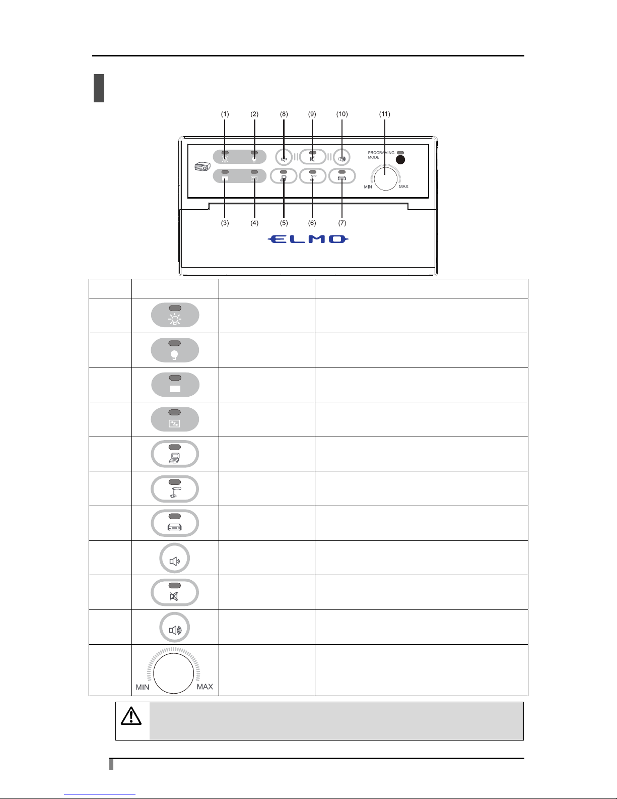
Operation panel
No. Button Button name Description
(1)
ON Turns on the power of the projector.
(2)
OFF Turns off the power of the projector.
(3)
BLANK
Blanks the projector output image, or
cancels the blanking.
(4)
SYNC Adjusts the screen.
(5)
Computer Enables RGB1 and AUDIO1.
(6)
Document Camera Enables RGB2 and AUDIO2.
(7)
VIDEO Enables VIDEO and AUDIO (L/R).
(8)*1
Volume Down Lowers the AUDIO volume.
(9)*1
MUTE Mutes AUDIO, or cancels the mute.
(10)*1
Volume Up Raises the AUDIO volume.
(11)*1
MIC Volume Adjusts the MIC volume.
Caution
*1 The volumes of the AUDIO and MIC are adjusted separately.
Page 11

11
Connectors
No. Symbol Connector name Description
(1)*1
AUDIO1 Audio input from “Computer”
(2)*1
AUDIO2 Audio input from “Document Camera”
(3)*1
MIC Audio input from “MIC”
(4)
VIDEO Image input from “VIDEO”
(5)*1 AUDIO L Audio input(left) from “VIDEO”
(6)*1 AUDIO R Audio input(right) from “VIDEO”
(7)*1
AUDIO Audio output
(8)
DC IN DC 12 V power supply
(9)
RGB1 Image input from “Computer”
(10)
RGB2 Image input from “Document Camera”
(11)
RGB Image output from “RGB”
(12) VIDEO Image output from “VIDEO”
(13)
RS-232C Projector control output
Caution
*1 MIC and the AUDIO1, AUDIO2 or AUDIO (L/R) output that is selected are
mixed before output.
Page 12

12
4. Preparations
Connection diagram
*1 Use the items that are supplied with this product. (For (8) and (9), use either one or the other.)
*2 For details on selecting the projector, see "Selecting a projector to use" on p.28.
*3 The bracket can be used for fixing the IR emitter. Fix it within the receiving range of the projector
with double-sided tape or screws.
*4 Use items that match the projector side terminal.
Page 13

13
Installation method
The procedure for fixing the unit in the fixing location with screws is described below.
Remove the two screws under the front cover, and remove the rear cover.
Cut out the oval perforated areas, and fix the unit in the fixing location
with screws.
The rectangle perforations are the holes for the expansion board. Do not
cut them out.
After fixing the unit with screws, reinstall the rear cover.
Page 14

14
Cable connections
The methods for connecting peripheral devices to the unit are described below. When
connecting the cables, fully and securely insert them into the connectors. If a connector
has fixing screws, tighten them securely.
1. AUDIO1 and RGB1
The input from the Computer. Connect RGB1 to the Computer output with a VGA cable,
and connect AUDIO1 to the Computer output with an audio cable (Φ3.5 mm stereo mini
plug).
2. AUDIO2 and RGB2
The input from the Document Camera. When the Document Camera is used, AUDIO2 is
not used.
Connect RGB2 to the Document Camera output with a VGA cable.
Caution
When using audio, connect the output terminal of the unit to AUDIO2 with an
audio cable (Φ3.5 mm stereo mini plug).
3. MIC
The microphone input. Connect with a Φ6.5 mm microphone plug.
4. RGB
The image output from “RGB”. Connect to the projector with a VGA cable.
5. VIDEO
The image output from “VIDEO”. Connect to the projector with a video cable.
6. VIDEO and AUDIO (L/R)
The composite video input. Connect the output of a VCR player or similar device to the
VIDEO and AUDIO (L/R) connectors with an RCA cable, matching the yellow (VIDEO),
white (L) and red (R) connector colors.
7. AUDIO
The audio output connector. Connect to an external speaker with an audio cable (Φ3.5
mm stereo mini plug).
Page 15

15
8. RS-232C
Connect the RS-232C connector of the unit to the projector control connector with the
supplied RS cable. For details on the projector to use, see "Selecting a projector to use"
on p.28.
A command table that is suitable for the projector must be selected. For details on
selecting the command table, see "Controlling with RS-232C" on p.16.
Projector settings must also be performed.
Caution
If you want to change the control command of the projector or there is no table
for the manufacturer of your projector, the contents of the command table must
be edited with the programming tool (sold separately). Contact your local
dealer.
If the projector does not have a control connector, operate it with IR control.
When performing IR control, see "Infrared learning function" on p.18.
9. IR
Connect the supplied IR cable to the RS-232C connector of the unit. Fix the LED area of
the IR cable in a position where the infrared receiver of the projector responds to it.
Perform learning for the unit to learn the remote control signals of your projector. For
details on the learning function, see "Infrared learning function" on p.18.
Not used when RS-232C control is performed.
10. DC IN
Connect the supplied AC Adapter to the power cable.
Page 16

16
Controlling with RS-232C
RS-232C protocol is used in control communication with the projector. Eight preset
command tables for projectors are available in the unit. Select the correct command table
that is suitable for your projector. The factory setting for the command table of the unit is
SANYO.
Caution
Command control for RGB applies when the unit is connected to the RGB1
connector of a projector. If a projector has multiple RGB connectors, connect
the cable to RGB1.
■ Procedure for selecting a preset table
While pressing and holding the unit's (ON) button and
(OFF) button (3 seconds), insert the AC Adapter.
When the buttons are released, all the LEDs other than PROGRAMMING
MODE flash and turn off.
Page 17

17
Press the button below that is suitable for your projector.
(Default: Table 1)
ON button - Table 1 (SANYO)
OFF button - Table 2 (HITACHI)
MUTE button - Table 3 (NEC)
BLANK button - Table 4 (EPSON)
SYNC button - Table 5 (SHARP)
Computer button - Table 6 (Canon)
Document Camera button - Table 7 (EIKI)
VIDEO button - Table 8 (InFocus)
The LED of the selected button turns on for 2 seconds, and after the
command table changes, the LED turns off and normal operation returns.
Connect the supplied RS cable to the unit and the projector.
Check that the projector you connected operates correctly when you
press the different buttons of the unit.
Caution
If you want to set a different table, perform this procedure again.
Page 18

18
Infrared learning function
■ Learning method
The unit is equipped with a learning function for infrared signals. This is for learning the
signals of the remote control that is supplied with a projector, to enable the remote control
operation of the projector from the unit.
Perform the learning by following the procedure below.
■ Learning procedure
While pressing and holding the unit's (BLANK) button and
(SYNC) button (3 seconds), insert the AC Adapter.
When the buttons are released, all the LEDs flash for 3 seconds, and then
all the LEDs except MUTE turn on.
Caution
In infrared learning mode, the LED of PROGRAMMING MODE is lit.
Page 19

19
Select the button that you want the unit to learn.
The selected button LED turns on.
ON button - Remote 1 (power button)
OFF button - Remote 2 (power button)
BLANK button - Remote 3 (image blank)
SYNC button - Remote 4 (image adjustment)
Computer button - Remote 5 (RGB input selection)
Document Camera button - Remote 6 (RGB input selection)
VIDEO button - Remote 7 (VIDEO input selection)
Caution
1) Make the unit learn the same signals for ON and OFF, and Computer and
Document Camera.
2) To cancel the learning, press the MUTE button.
Make the unit learn the remote control signal that corresponds to the
button.
Point the remote control of the projector toward the infrared receiver of the unit and press
the button you want the unit to learn for 1 to 2 seconds.
When pointing the remote control toward the infrared receiver of the unit, keep it
perpendicular to the receiver and within 3 cm.
Caution
Perform learning within 35 seconds of selecting the button on the unit.
When learning is successful, the LED flashes, and then all the LEDs
except MUTE turn on again.
Repeat the procedure from step until all the buttons have learned remote control
signals.
Caution
If learning fails, the MUTE LED turns on. Press the MUTE button and perform
learning again from step . Also repeat in this way if you make a mistake in
the learning operation.
Page 20

20
To finish learning, press the (MUTE) button.
Normal operation returns.
Connect the supplied IR cable to the unit, and fix the IR emitter in a
position where the remote control receiver of the projector responds to it.
Check that the projector you connected operates correctly when you
press the different buttons of the unit.
Caution
1) Learning may not be possible with some remote control signals.
2) If you make the unit learn two or more functions for a single button, you
must be very careful when operating it.
(1) ON/OFF button of the remote control
If you performed learning for a remote control signal that controls power
on and off, and you press the ON button of the unit while the projector is
running, a message such as "Press again to turn off the projector
power" will be displayed. If you press the button again, the projector will
turn off. Do not touch the unit's ON button while the projector is running.
Also, if you press the OFF button while the projector is in standby, the
projector will start up. Do not touch the unit's OFF button while the
projector is not running.
(2) Video image selection button of the remote control
Projectors that have multiple video image inputs may have a single
remote control button that changes the inputs in sequence.
With such projectors, if you continuously input this selection remote
control signal, the projector input may change and the video image that
you want to display may not be shown. Press down the video image
selection button in short intervals until the video image that you want to
display is shown.
Page 21

21
5. Operating the Unit
Operation
Select either the Computer, Document Camera or VIDEO input to determine the image and
audio to output from the unit.
Below is a simple description of how to operate the unit.
Complete all the peripheral device connections and unit settings, and
then connect the power cord to the outlet.
To turn on the projector power, press the (ON) button.
The projector power turns on, the green LED of the ON button flashes. When the LED of
the ON button stops flashing and stays on, the red LED of Computer turns on and the
RGB1 image and AUDIO1 audio are output.
To turn off the projector power, press the (OFF) button.
The audio output and projector power turn off. The red LED of the OFF button flashes.
When the LED of the OFF button stops flashing, the OFF LED stays on.
Caution
After pressing the OFF button, leave some cooling time before using the
projector again.
Do not press the ON button while the projector is cooling.
To adjust the AUDIO volume, press / (Volume Up/Down).
To mute, press the (MUTE) button.
When the mute is operating, the red LED on the button is lit.
To cancel the mute, press the button again.
Caution
The MIC volume does not change with Volume Up/Down.
Adjust the volume of a connected microphone with MIC Volume.
To mute, turn MIC Volume until it stops on the MIN side.
Caution
The AUDIO volume does not change with MIC Volume.
To blank the image, press the (BLANK) button.
When the image is blanked, the red LED is lit. To cancel, press the BLANK button again.
The LED turns off.
Page 22

22
To adjust the image, press the (SYNC) button.
The image that is output from the input signal is adjusted. When the button is pressed, the
red LED flashes 3 times, the adjustment is performed, and then the LED turns off.
To output the image and audio from "Computer", press the (Computer)
button.
The red LED turns on and the RGB1 image and AUDIO1 audio are output.
To output the image from "Document Camera", press the
(Document Camera) button.
The red LED turns on and the RGB2 image is output.
Caution
If there is an input to AUDIO2, audio is also output.
To output the image and audio from "VIDEO", press the (VIDEO)
button.
The red LED turns on and the VIDEO image and AUDIO (L/R) audio are output.
Page 23

23
When there are connectors not connected to peripheral devices
After connecting the peripheral devices, if there are connectors that are not connected to
anything, be careful of the following.
1. RGB1 and AUDIO1 are not connected
Do not use Computer on the operation panel.
Select a selection button that has image input.
2. RGB2 and AUDIO2 are not connected
Do not use Document Camera on the operation panel.
3. VIDEO (input) and AUDIO (L/R) are not connected
Do not use VIDEO on the operation panel.
4. AUDIO (input) or MIC are not connected
Audio is not input.
5. RGB (output) is not connected
The image from an RGB input device is not displayed. If there is an RGB image input, be
sure to connect it to the projector.
6. VIDEO (output) is not connected
The image from VIDEO input is not output. If there is a VIDEO image input, be sure to
connect it to the projector.
7. AUDIO (output) is not connected
The audio from AUDIO input and MIC input is not output.
8. RS-232C is not connected
If the RS-232C connector is not connected, projector control is not possible. Connect with
the supplied RS cable or IR cable so that the projector can be controlled.
Page 24

24
6. Troubleshooting
If there is still an abnormality after checking the items below, contact the dealer where you
purchased the unit, or our nearest branch office or sales office. We will perform repairs in
accordance with our policy.
Item Checks
Unit does not function
Is the AC Adapter connected?
Check the connection between the unit and the outlet.
Has the power cable disconnected?
Check the connection between the AC Adapter and the
power cable.
Projector does not operate
Is the projector's power turned on?
Are the projector and the unit connected correctly?
Is the pin of the MiniDIN8 connector short-circuiting for
some reason?
Remove the cause of the problem.
Is the command table of the projector set correctly?
See "Controlling with RS-232C" on p.16.
Have the suitable remote control signals been learned?
See "Infrared learning function" on p.18.
Is the installation location of the IR emitter suitable?
If installed in a location exposed to strong light, the IR
signal may not reach the receiver.
Image is not output
Are the video cables fully inserted?
Is a cable broken?
Do not use old cables.
Is the LED of the BLANK button lit?
If the LED is lit, press the BLANK button again.
Cannot change the image
Is the button you selected correct?
Select a button that has image input.
Is the projector control cable connected and positioned
correctly?
If the projector input cannot be selected, output may not be
possible.
Is there an input from a video device?
Image is distorted
Are the connectors fully and securely inserted?
Is the input signal capable of being displayed by the
projector?
Is the cable securely fixed to the connector?
Is a cable broken?
Do not use old cables.
Page 25

25
Item Checks
No sound
Has a cable disconnected?
Are the cables connected correctly?
Check that the insertion location is correct.
Is there an input from an audio device?
Is the AUDIO volume set to the minimum?
Is the MUTE LED lit?
If the LED is lit, press the MUTE button to cancel the mute.
Is the speaker's power turned on?
Is the speaker volume set to the minimum?
Cannot hear the microphone
sound
Has a cable disconnected?
Is the MIC Volume set to MIN?
Is the speaker's power turned on?
Is the speaker volume set to the minimum?
Cannot perform infrared
learning
Are you performing the operations correctly?
See "Infrared learning function" on p.18.
Is learning possible for the remote control that you want to
use?
If the LED of the MUTE button turns on no matter how
many times you perform the operation, learning is not
possible.
Is there enough power remaining in the remote control's
batteries?
Caution
If proper operation is still not possible after checking the items above, there
may be a malfunction in the unit.
Contact your local dealer for repair.
Page 26

26
7. Specifications
These are the specifications of the unit. Check these before using the unit.
Item Connector Check item Specification
Analog RGB RGB1 Connector type Dsub15 (female)
Video signal 0.7 Vp-p/75 Ω
Synchronizing signal level TLL level
Video frequency characteristics 400 MHz, 3 dB or higher
Resolution VGA to SXGA, 1080p
RGB2 Connector type Dsub15 (female)
Video signal 0.7 Vp-p/75 Ω
Synchronizing signal level TLL level
Video frequency characteristics 400 MHz, 3 dB or higher
Resolution VGA to SXGA, 1080p
RGB Connector type Dsub15 (female)
Video signal 0.7 Vp-p/75 Ω
Synchronizing signal level TLL level
Video frequency characteristics 400 MHz, 3 dB or higher
Resolution VGA to SXGA, 1080p
Video VIDEO Connector type RCA pin jack
VBS signal 0.7 Vp-p/75 Ω
VIDEO
(Output)
Connector type RCA pin jack
VBS signal No output distortion or
attenuation.
Audio AUDIO1 Connector type Φ3.5 mm stereo mini jack
Input impedance 8000 Ω (right/left)
Maximum input level Maximum volume at 1.0 V:
Gain=1.89
AUDIO2 Connector type Φ3.5 mm stereo mini jack
Input impedance 8000 Ω (right/left)
Maximum input level Maximum volume at 1.0 V:
Gain=1.89
VIDEO
(L/R)
Connector type RCA pin jack
Input impedance 8000 Ω (right/left)
Maximum input level Maximum volume at 1.0 V:
Gain=1.89
AUDIO Connector type Φ3.5 mm stereo mini jack
Audio frequency band 280 Hz to 20 KHz
Output impedance 500 Ω (right/left)
Output level variable range 2.0 V
Microphone MIC Connector type Φ6.5 mm microphone jack
Microphone type Condenser microphone,
moving-coil microphone
Input impedance 21400 Ω
Page 27

27
Item Connector Check item Specification
RS-232C RS-232C Connector type Dsub9 (female)
No. of tables 8
No. of commands 6
Baud rate 4800/9600/19200/38400/115200
bps
Data bits 7 bits, 8 bits
Stop bits 1 bits, 1.5 bits, 2 bits
Parity bit non/odd/even
Cable length 15 m (standard value)
Cable type When using a specified projector,
use the supplied cable
In other cases, an option and cable
are required
Supported projectors SANYO, HITACHI, NEC, EPSON,
SHARP, Canon,
EIKI, InFocus
Infrared
output
RS-232C Connector type Dsub9 (female)
Learning Operating distance Max 3 cm
No. of learning items 7 buttons
Frequency 30 KHz - 42 KHz
Output No. of operations 7
ON, OFF, BLANK, SYNC,
Computer, Document Camera,
VIDEO
Cable type Use the supplied cable
Main unit Item Specification
Unit
specifications
Power voltage 12 VDC (AC Adapter AC100 – 240 V)
Power
consumption
No device connected - 2.1 W All connected - 3.3 W
External
dimensions
L-168 mm/H-90 mm/W-43 mm (including volume knob:
58 mm)
Weight 306 g
Operating
temperature
range
0 - 40°C
Supplied items AC Adapter
Power cable
RS cable
IR cable
Bracket
CD-ROM (Instruction Manual)
Warranty certificate
Page 28

28
8. Appendix
Selecting a projector to use
■ Recommended models (as of February 2010)
1. Use the RS cable's Dsub9 connector
SANYO : LP-XW200 / LP-XW250 / LP-XW300
HITACHI : CP-X308J / CP-X417J / CP-X3010J / CP-X2510J
NEC : NP600SJ / NP500WSJ / NP215J / NP210J / NP115J / NP110J
EPSON : EB-410W / EB-826W / EB-825 / EB-85
SHARP : PG-F255W / PG-F312X / PG-F212X
Canon : LV-7375 / LV-7370 / LV-7275 / LV-8300
EIKI : LC-XS25D / LC-XS30D
InFocus : IN2100 / IN2104EP
2. Use the RS cable's MiniDIN8 connector
SANYO : LP-XW60 / LP-XW65 / LP-WXL46
EIKI : LC-XB42D
The command table can be changed using the supplied programming tool.
To use the programming tool, a programming cable (sold separately) is required to
connect the Computer on which the programming tool is installed to the unit.
To purchase, contact your local dealer.
Caution
If your projector is not in the recommended list or it does not have a control
connector, control it using IR.
If you cannot make it operate properly, contact your local dealer.
Page 29

29
RS-232C command tables
This section shows the RS-232C commands that are registered in the unit.
The commands in the tables are HEX codes.
Computer and Document Camera use the same commands.
SANYO(table1) HITACHI(table2)
BUTTON COMMAND BUTTON COMMAND
Baud rate 19200 Baud rate 19200
ON 4330300D ON BEEF030600BAD2010000600100
OFF 4330310D OFF BEEF0306002AD3010000600000
SYNC ON 4338390D SYNC ON BEEF03060091D006000A200000
SYNC OFF 4338390D SYNC OFF BEEF03060091D006000A200000
BLANK ON 4330440D BLANK ON BEEF0306006BD9010020300100
BLANK OFF 4330450D BLANK OFF BEEF030600FBD8010020300000
Computer 4330350D Computer BEEF030600FED2010000200000
Document Camera Document Camera
VIDEO 4330370D VIDEO BEEF0306006ED3010000200100
NEC(table3) EPSON(table4)
BUTTON COMMAND BUTTON COMMAND
Baud rate 19200 Baud rate 9600
ON 020000000002 ON 505752204F4E0D
OFF 020100000003 OFF 505752204F46460D
SYNC ON 020F000002050018 SYNC ON 4B45592034410D
SYNC OFF 020F000002050018 SYNC OFF 4B45592034410D
BLANK ON 021000000012 BLANK ON 4D555445204F4E0D
BLANK OFF 021100000013 BLANK OFF 4D555445204F46460D
Computer 0203000002010109 Computer 534F555243452031310D
Document Camera Document Camera
VIDEO 020300000201060E VIDEO 534F555243452034310D
Page 30

30
SHARP(table5) Canon(table6)
BUTTON COMMAND BUTTON COMMAND
Baud rate 9600 Baud rate 19200
ON 504F5752202020310D ON 020000000002
OFF 504F5752202020300D OFF 020100000003
SYNC ON 41444A53202020310D SYNC ON 020F000002050018
SYNC OFF 41444A53202020310D SYNC OFF 020F000002050018
BLANK ON 494D424B202020310D BLANK ON 021000000012
BLANK OFF 494D424B202020300D BLANK OFF 021100000013
Computer 49524742202020310D Computer 0203000002010109
Document Camera
Document Camera
VIDEO 49564544202020320D VIDEO 020300000201060E
EIKI(table7) InFocus(table8)
BUTTON COMMAND BUTTON COMMAND
Baud rate 19200 Baud rate 115200
ON 4330300D ON 50575231
OFF 4330310D OFF 50575230
SYNC ON 4338390D SYNC ON 41494D
SYNC OFF 4338390D SYNC OFF 41494D
BLANK ON 4330440D BLANK ON 424C4B31
BLANK OFF 4330450D BLANK OFF 424C4B30
Computer 4330350D Computer 44534330
Document Camera Document Camera
VIDEO 4330370D VIDEO 44534332
Page 31

31
9. Separately Sold Options
These options expand the functions of the product.
Description Item Specification
Expansion board
Connector DC IN, AUDIO, RGB, VIDEO (Output), RS-232C
External
dimensions
L-112 mm/H-20 mm/W-84 mm
Weight 105 g
Programming cable -
A cable for connecting the unit to the Computer on
which the programming tool is installed
is a registered trademark of ELMO Co., Ltd.
Company/product names described in this manual are trademarks or registered trademarks of
their respective companies.
6-14, Meizen-cho, Mizuho-ku
Nagoya, 467-8567, Japan
OVERSEAS SUBSIDIARY COMPANIES
ELMO USA CORP.
Headquarters
1478 Old Country Road
Plainview, NY 11803-5034, U.S.A.
Tel. (516) 501-1400 Fax. (516) 501-0429
E-mail:elmo@elmousa.com
Web:http://www.elmousa.com
West Coast Branch
Cypress Pointe Business Park
5676 Corporate Avenue
Cypress, CA 90630, U.S.A.
Tel. (714) 828-8457 Fax. (714) 828-8429
ELMO (Europe) G.m.b.H.
Neanderstr. 18,
40233 Düsseldorf, Germany
Tel. (0211) 386470 Fax. (0211) 376620
E-mail:info@elmoeurope.com
Web:http://www.elmoeurope.com
6X1CRCA02 R1-Xb
 Loading...