

Elmo Bassoon Installation Manual

Bassoon
Digital Servo Drive
Installation Guide
August 2008 (Ver. 1.4)
www.elmomc.com
Notice
This guide is delivered subject to the following conditions and restrictions:
This guide contains proprietary information belonging to Elmo Motion
Control Ltd. Such information is supplied solely for the purpose of assisting
users of the Bassoon servo drive in its installation.
The text and graphics included in this manual are for the purpose of
illustration and reference only. The specifications on which they are based
are subject to change without notice.
Elmo Motion Control and the Elmo Motion Control logo are trademarks of
Elmo Motion Control Ltd.
Information in this document is subject to change without notice.
Document No. MAN-BASIG
Copyright © 2008
Elmo Motion Control Ltd.
All rights reserved.
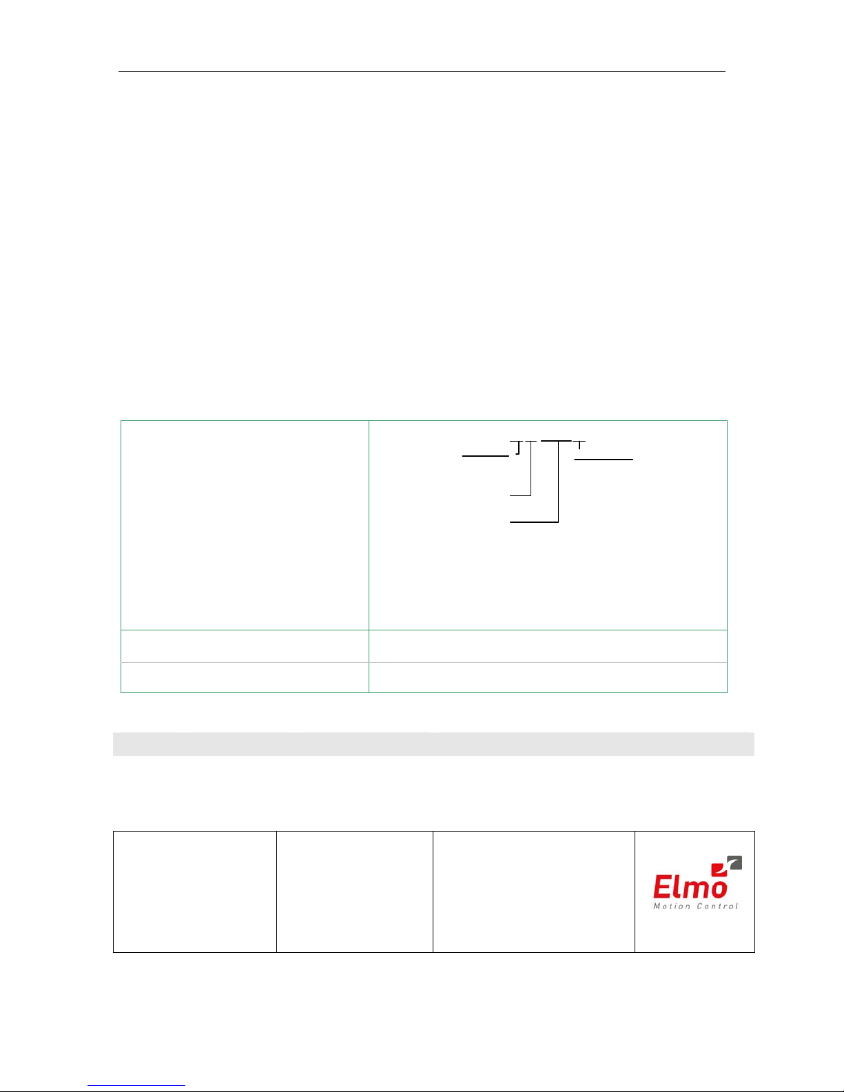
Bassoon Catalog Number:
Nominal AC
Operating Voltage
Continuous Current
(Amp s )
Version:
Blank = Standard
A = Advanced
Feedback:
Blank = Incremental
Encoder
and/or Halls
R=Resolver
BAS- A 1/230R
T=
Tachometer &
Potentiometer
I = Interpolated
Analog
Encoder
A=
Absolute
Encoder
S=
Stegmann
Absolute
Encoder
Cable Kit Catalog Number
HAR-CABLEKIT (kit available upon request)
Related Document
MAN-CABLEKIT (available on our website)
Revision History:
Version Release Date Status/Doc Code Changes/Remarks
Ver 1.4 August 2008 draft Added 3.5.6.4: Differential pulse-and–direction input
Ver. 1.3 April 2008 MAN-BASIG.pdf Updated Power Ratings Table in Appendix
Elmo Motion Control Ltd.
64 Gissin St., P.O. Box 463
Petach Tikva 49103
Israel
Tel: +972 (3) 929-2300
Fax: +972 (3) 929-2322
info-il@elmomc.com
Elmo
Motion Control Inc.
1 Park Drive, Suite 12
Westford, MA 01886
USA
Tel: +1 (978) 399-0034
Fax: +1 (978) 399-0035
info-us@elmomc.com
Elmo Motion Control GmbH
Steinkirchring 1
D-78056, Villingen-Schwenningen
Germany
Tel: +49 (0) 7720-85 77 60
Fax: +49 (0) 7720-85 77 70
info-de@elmomc.com
www.elmomc.com

Contents
Chapter 1: Safety Information.............................................................................................. 1-1
1.1 Warnings ......................................................................................................... 1-2
1.2 Cautions........................................................................................................... 1-2
1.3 Directives and Standards............................................................................... 1-3
1.4 CE Mark Conformance .................................................................................. 1-3
1.5 Warranty Information.................................................................................... 1-3
Chapter 2: Introduction ......................................................................................................... 2-1
2.1 Drive Description ........................................................................................... 2-1
2.2 Product Features............................................................................................. 2-1
2.2.1 Current Control.........................................................................................2-1
2.2.2 Velocity Control........................................................................................2-1
2.2.3 Position Control ........................................................................................2-2
2.2.4 Advanced Position Control (Advanced model only)...............................2-2
2.2.5 Communication Options .........................................................................2-2
2.2.6 Feedback Options .....................................................................................2-2
2.2.7 Fault Protection.........................................................................................2-3
2.3 System Architecture....................................................................................... 2-3
2.4 How to Use this Guide................................................................................... 2-4
Chapter 3: Installation........................................................................................................... 3-1
3.1 Before You Begin ............................................................................................ 3-1
3.1.1 Site Requirements.....................................................................................3-1
3.1.2 Hardware Requirements .........................................................................3-1
3.1.3 AC Power Requirements .........................................................................3-3
3.2 Unpacking the Drive Components ............................................................... 3-3
3.3 Assembling the Heatsink............................................................................... 3-4
3.4 Mounting the Bassoon ................................................................................... 3-4
3.4.1 Mounting on a DIN Rail ..........................................................................3-4
3.4.2 Mounting Directly onto a Wall...............................................................3-5
3.5 Connecting the Cables ................................................................................... 3-5
3.5.1 Wiring the Bassoon...................................................................................3-5
3.5.2 Connecting the Power Cables .................................................................3-8
3.5.2.1 Connecting the Motor Cable.....................................................3-8
3.5.2.2 Connecting the Main Power Cable...........................................3-9
3.5.3 Connecting the Auxiliary Power Cable (J4)....................................... 3-10
3.5.4 Feedback and Control Cable Assemblies ........................................... 3-11
3.5.5 Main Feedback Cable (Port J3)............................................................. 3-12
3.5.6 Main and Auxiliary Feedback Combinations.................................... 3-20
3.5.6.1 Main Encoder Buffered Outputs or Emulated Encoder
Outputs Option on FEEDBACK B (J2) (YA[4]=4) ..............................
3-21
3.5.6.2 Differential Auxiliary Encoder Input Option on
FEEDBACK B (J2) (YA[4]=2)................................................................
3-22
Bassoon Installation Guide Contents
MAN-BASIG (Ver 1.4)
i

3.5.6.3 Single-ended Auxiliary Input Option on FEEDBACK B (J2)
(YA[4]=2)................................................................................................
3-23
3.5.6.4 Pulse-and-Direction Input Option on FEEDBACK B (J2)
(YA[4]=0)................................................................................................
3-25
3.5.7 I/O Cables ..............................................................................................3-27
3.5.7.1 Digital Input (Port J5) ............................................................. 3-27
3.5.7.2 Digital Output (Port J6) .......................................................... 3-29
3.5.7.3 Analog Input (Port J7) ............................................................ 3-30
3.5.8 Communication Cable (Port J1, J8, J9) ................................................3-31
3.5.8.1 RS-232 Communication.......................................................... 3-31
3.5.8.2 CANopen Communication .................................................... 3-32
3.6 Powering Up..................................................................................................3-34
3.7 Initializing the System ..................................................................................3-34
Appendix: Technical Specifications.................................................................................... A-1
A.1 Features .......................................................................................................... A-1
A.1.1 Motion Control Modes............................................................................ A-1
A.1.2 Advanced Positioning Motion Control Modes ................................... A-1
A.1.3 Advanced Filters and Gain Scheduling................................................ A-1
A.1.4 Fully Programmable................................................................................ A-1
A.1.5 Feedback Options .................................................................................... A-1
A.1.6 Input/Output........................................................................................... A-2
A.1.7 Built-In Protection.................................................................................... A-2
A.2 Bassoon Dimensions......................................................................................A-3
A.3 General Specifications................................................................................... A-4
A.4 Environmental Conditions ........................................................................... A-4
A.5 Bassoon Connectors ......................................................................................A-5
A.5.1 Connector Types ...................................................................................... A-5
A.5.2 Control and Feedback Connector Specifications................................. A-5
A.6 Auxiliary Power Supply (J4) ........................................................................ A-7
A.7 Control Specifications ................................................................................... A-7
A.7.1 Current Loop............................................................................................ A-7
A.7.2 Velocity Loop ........................................................................................... A-8
A.7.3 Position Loop............................................................................................ A-8
A.8 Feedback......................................................................................................... A-9
A.8.1 Feedback Supply Voltage ....................................................................... A-9
A.8.2 Incremental Encoder ............................................................................... A-9
A.8.3 Digital Halls............................................................................................ A-10
A.8.4 Interpolated Analog Encoder (Sine/Cosine) ..................................... A-10
A.8.5 Resolver................................................................................................... A-11
A.8.6 Tachometer*............................................................................................ A-11
A.8.7 Potentiometer ......................................................................................... A-12
A.8.8 Encoder Outputs.................................................................................... A-12
A.9 I/Os............................................................................................................... A-13
A.9.1 Digital Input Interfaces ......................................................................... A-13
A.9.2 Digital Output Interface........................................................................ A-14
A.9.3 Analog Input (J7) ................................................................................... A-16
A.10 Communications.......................................................................................... A-16
A.11 Pulse Width Modulation (PWM) ............................................................... A-18
A.12 Heatsink Specifications............................................................................... A-18
A.13 Standards Compliance ................................................................................ A-19
Bassoon Installation Guide Contents
MAN-BASIG (Ver 1.4)
ii

A.13.1 Quality Assurance ................................................................................. A-19
A.13.2 Design...................................................................................................... A-19
A.13.3 Safety ....................................................................................................... A-20
A.13.4 EMC ......................................................................................................... A-20
A.13.5 Workmanship......................................................................................... A-20
A.13.6 PCB .......................................................................................................... A-20
A.13.7 Packing .................................................................................................... A-20
Index...........................................................................................................................................I-1
Bassoon Installation Guide Contents
MAN-BASIG (Ver 1.4)
iii
Chapter 1: Safety Information
In order to achieve the optimum, safe operation of the Bassoon servo drive, it is
imperative that you implement the safety procedures included in this installation
guide. This information is provided to protect you and to keep your work area safe
when operating the Bassoon and accompanying equipment.
Please read this chapter carefully before you begin the installation process.
Before you start, ensure that all system components are connected to earth ground.
Electrical safety is provided through a low-resistance earth connection.
Only qualified personnel may install, adjust, maintain and repair the servo drive. A
“qualified person” has the knowledge and authorization to perform tasks such as
transporting, assembling, installing, commissioning and operating motors.
The Bassoon servo drive contains electrostatic-sensitive components that can be
damaged if handled incorrectly. To prevent any electrostatic damage, avoid contact
with highly insulating materials, such as plastic film and synthetic fabrics. Place the
product on a conductive surface and ground yourself in order to discharge any
possible static electricity build-up.
To avoid any potential hazards that may cause severe personal injury or damage to
the product during operation, keep all covers and cabinet doors shut.
The following safety symbols are used in this manual:
Warning:
This information is needed to avoid a safety hazard, which might
cause bodily injury.
Caution:
This information is necessary for preventing damage to the product
or to other equipment.
Note:
This is auxiliary information that ensures the correct operation of
the equipment.
Bassoon Installation Guide
MAN-BASIG (Ver 1.4)
1-1
1.1 Warnings
To avoid electric arcing and hazards to personnel and electrical
contacts, never connect/disconnect the servo drive while the power
source is on.
Power cables can carry a high voltage, even when the motor is not in
motion. Disconnect the Bassoon from all voltage sources before it is
opened for servicing.
The Bassoon servo drive contains grounding conduits for electric
current protection. Any disruption to these conduits may cause the
device to become “hot” (live) and dangerous.
After shutting off the power and removing the power source from
your equipment, wait at least 1 minute before touching or
disconnecting parts of the equipment that are normally loaded with
electrical charges (such as capacitors or contacts). Measuring the
electrical contact points with a meter before touching the equipment
is recommended.
1.2 Cautions
The Bassoon servo drive contains hot surfaces and electrically-charged
components during operation.
The maximum AC power supply connected to the instrument must
comply with the parameters outlined in this guide.
The Bassoon drive must be connected to an approved 24VDC
auxiliary power supply through a line that is separated from
hazardous line voltages using reinforced or double insulation in
accordance with approved safety standards.
The Bassoon X/230 series is designed to gets its power from a 30 ~
255 VAC single phase power source. It can be connected directly to
the line voltage. An isolation transformer is not needed.
Before switching on the Bassoon, verify that all safety precautions
have been observed and that the installation procedures in this manual
have been followed.
Bassoon Installation Guide Safety Information
MAN-BASIG (Ver 1.4)
1-2

1.3 Directives and Standards
The Bassoon conforms to the following industry safety standards:
Safety Standard Item
In compliance with UL508c and
UL840
Conformance to the following safety standards:
Power Conversion Equipment
Insulation Coordination, Including
Clearance and Creepage Distances of
Electrical Equipment
In compliance with UL60950
(formerly UL1950)
Safety of Information Technology Equipment,
Including Electrical Business Equipment
In compliance with EN60204-1 Low Voltage Directive, 73/23/EEC
The Bassoon servo drive has been developed, produced, tested and documented in
accordance with the relevant standards. Elmo Motion Control is not responsible for
any deviation from the configuration and installation described in this documentation.
Furthermore, Elmo is not responsible for the performance of new measurements or
ensuring that regulatory requirements are met.
1.4 CE Mark Conformance
The Bassoon servo drive is intended for incorporation in a machine or end product.
The actual end product must comply with all safety aspects of the relevant
requirements of the European Safety of Machinery Directive 98/37/EC as amended,
and with those of the most recent versions of standards EN60204-1 and EN292-2 at the
least.
According to Annex III of Article 13 of Council Directive 93/68/EEC, amending
Council Directive 73/23/EEC concerning electrical equipment designed for use within
certain voltage limits, the Bassoon meets the provisions outlined in Council Directive
73/23/EEC. The party responsible for ensuring that the equipment meet the limits
required by EMC regulations is the manufacturer of the end product.
1.5 Warranty Information
The products covered in this manual are warranted to be free of defects in material
and workmanship and conform to the specifications stated either within this
document or in the product catalog description. All Elmo drives are warranted for a
period of 12 months from the time of installation, or 18 months from time of shipment,
whichever comes first. No other warranties, expressed or implied — and including a
warranty of merchantability and fitness for a particular purpose — extend beyond this
warranty.
Bassoon Installation Guide Safety Information
MAN-BASIG (Ver 1.4)
1-3

Bassoon Installation Guide
MAN-BASIG (Ver 1.4)
2-1
Chapter 2: Introduction
This installation guide describes the Bassoon servo drive and the steps for its wiring,
installation and powering up. Following these guidelines ensures maximum
functionality of the drive and the system to which it is connected.
2.1 Drive Description
The Bassoon is a powerful servo drive that operates in digital current, velocity,
position and advanced position modes, in conjunction with a permanent-magnet
synchronous brushless motor or DC brush motor. The Bassoon features flexible
sinusoidal and trapezoidal commutation, with vector control. The Bassoon can operate
as a stand-alone device or as part of a multi-axis network in a distributed
configuration.
The Bassoon drive is set up and tuned using Elmo’s Composer software. This
Windows-based application enables users to quickly and simply configure the servo
drive for optimal use with their motor.
The Bassoon connects directly to 110/230 VAC single-phase power source. A separate
24 VDC power supply serves as both the auxiliary supply and the backup supply. This
allows a safe and economical "power backup" feature that is essential for positioning
systems.
Two variations of the Bassoon are available: the Standard version and the Advanced
version, which features advanced positioning capabilities. Both versions operate with
RS-232 and/or CANopen communications.
2.2 Product Features
2.2.1 Current Control
y Fully digital
y Sinusoidal commutation with vector control or trapezoidal
commutation with resolver, encoder and/or digital Hall sensors
y 12-bit current loop resolution
y Automatic gain scheduling, to compensate for variations in the DC
bus power supply
2.2.2 Velocity Control
y Fully digital
y Programmable PI and FFW (feed forward) control filters
y Sample rate two times current loop sample time
y “On-the-fly” gain scheduling
y Automatic, manual and advanced manual tuning and determination
of optimal gain and phase margins

Bassoon Installation Guide Introduction
MAN-BASIG (Ver 1.4)
2-2
2.2.3 Position Control
y Programmable PIP control filter
y Programmable notch and low-pass filters
y Position follower mode for monitoring the motion of the slave axis
relative to a master axis, via an auxiliary encoder input
y Pulse-and-direction inputs
y Sample time: four times that of current loop
y Fast event capturing inputs
2.2.4 Advanced Position Control (Advanced model only)
y Position-based and time-based ECAM mode that supports a non-
linear follower mode, in which the motor tracks the master motion
using an ECAM table stored in flash memory
y PT and PVT motion modes
y Dual (position/velocity) loop
y Fast output compare (OC)
2.2.5 Communication Options
Depending on the application, Bassoon users can select from two communication
options:
y RS-232 serial communication
y CANopen for fast communication in a multi-axis distributed
environment
2.2.6 Feedback Options
y Incremental Encoder – up to 20 Mega-Counts (5 Mega-Pulse) per
second
y Digital Halls – up to 2 KHz
y Incremental Encoder with Digital Halls for commutation – up to 20 Mega-
Counts per second for encoder
y Absolute Encoder
y Interpolated Analog Sine/Cosine Encoder – up to 250 KHz (analog
signal)
Internal Interpolation – programmable up to
X4096
Automatic Correction of:
y amplitude mismatch
y phase mismatch
y signals offset
Encoder outputs, buffered, differential
y Resolver
Programmable 10~15 bit resolution
Up to 512 revolutions per second (RPS)
Encoder outputs, buffered, differential
Bassoon Installation Guide Introduction
MAN-BASIG (Ver 1.4)
2-3
y Tachometer and Potentiometer
Two inputs for Tachometer Feedback:
y Up to ±50 VDC
y Up to ±20 VDC
Potentiometer Feedback:
y 0 ~ 5 V voltage range
y Resistance: 100 Ω to 1000 Ω
y Elmo drives provide supply voltage for all the feedback options
2.2.7 Fault Protection
The Bassoon includes built-in protection against possible fault conditions, including:
y Software error handling
y Status reporting for a large number of possible fault conditions
y Protection against conditions such as excessive temperature,
under/over voltage, loss of commutation signal, short circuits
between the motor power outputs and between each output and
power input/return
y Recovery from loss of commutation signals and from communication
errors
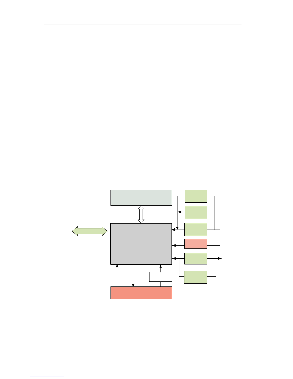
2.3 System Architecture
PWM
Controller
Communication
RS 232 and CANopen
Power Stage
Protection
Current
Feedback
Main
Encoder
SMPS
24 VDC
I/Os
Emulated
Output
Resolver
Analog
Encoder
Auxiliary
Encoder
or
or
Figure 2-1: Bassoon System Block Diagram
Bassoon Installation Guide Introduction
MAN-BASIG (Ver 1.4)
2-4
2.4 How to Use this Guide
In order to install and operate your Elmo Bassoon servo drive, you will use this
manual in conjunction with a set of Elmo documentation. Installation is your first step;
after carefully reading the safety instructions in the first chapter, the following
chapters provide you with installation instructions as follows:
Chapter 3, Installation, provides step-by-step instructions for unpacking, mounting,
connecting and powering up the Bassoon.
The Appendix, Technical Specifications, lists all the drive ratings and specifications.
Upon completing the instructions in this guide, your Bassoon servo drive should be
successfully mounted and installed. From this stage, you need to consult higher-level
Elmo documentation in order to set up and fine-tune the system for optimal operation.
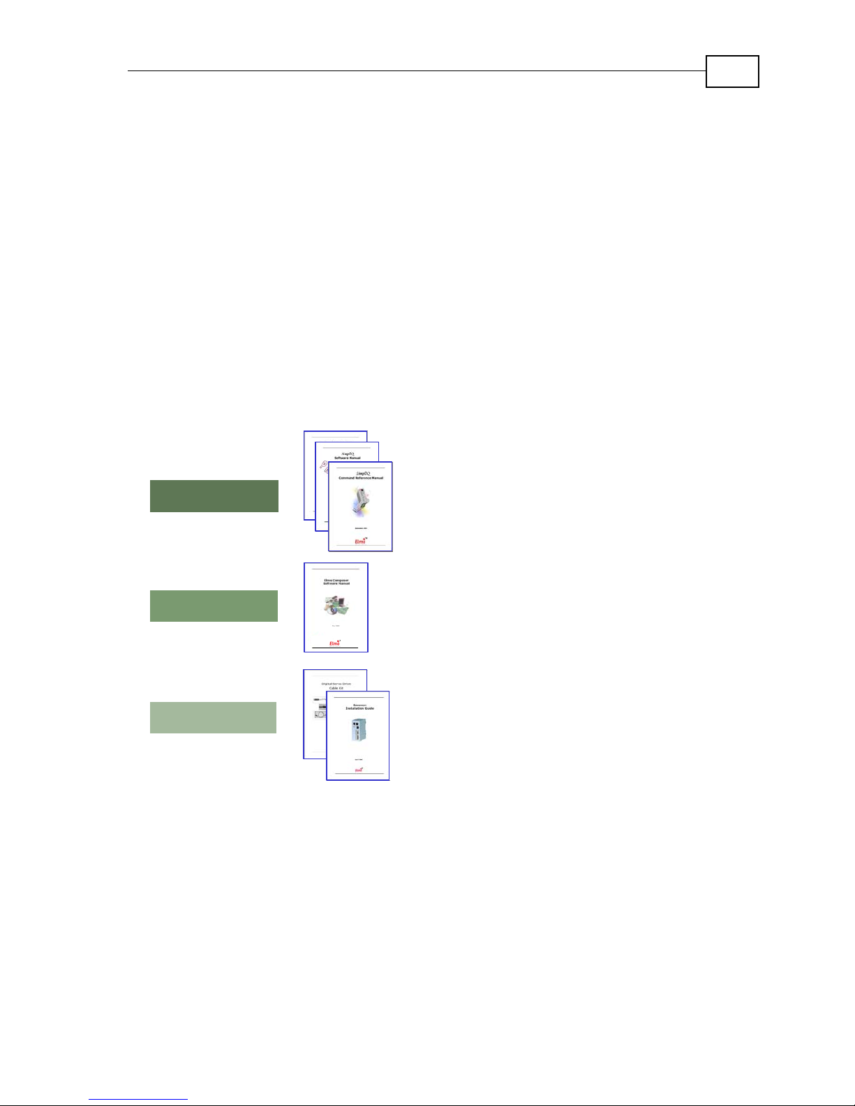
The following figure describes the accompanying documentation that you will
require.
SimplIQ Command Reference Manual
Bassoon Installation Guide
SimplIQ Software Manual
Programming
Setup
Installation
Composer User Manual
CANopen Implementation Guide
Digital Servo Drive Cable Kit
Figure 2-2: Elmo Documentation Hierarchy
As depicted in the previous figure, this installation guide is an integral part of the
Bassoon documentation set, comprising:
y The Composer Software Manual, which includes explanations of all
the software tools that are part of Elmo’s Composer software
environment.
y The SimplIQ Command Reference Manual, which describes, in detail,
each software command used to manipulate the Bassoon motion
controller.
y The SimplIQ Software Manual, which describes the comprehensive
software used with the Bassoon.
Chapter 3: Installation
3.1 Before You Begin
3.1.1 Site Requirements
You can guarantee the safe operation of the Bassoon by ensuring that it is installed in an
appropriate environment.
Feature Value
Ambient operating temperature 0 °C – 40 °C (32 °F – 104 °F)
Maximum operating altitude 10,000 m (30,000 ft)
Maximum relative humidity 90% non-condensing
Operating area atmosphere No flammable gases or vapors permitted in area
Models for extended environmental conditions are available.
The Bassoon dissipates its heat by natural convection. The maximum
operating ambient temperature of 0 °C – 40 °C (32 °F – 104 °F) must not be
exceeded.
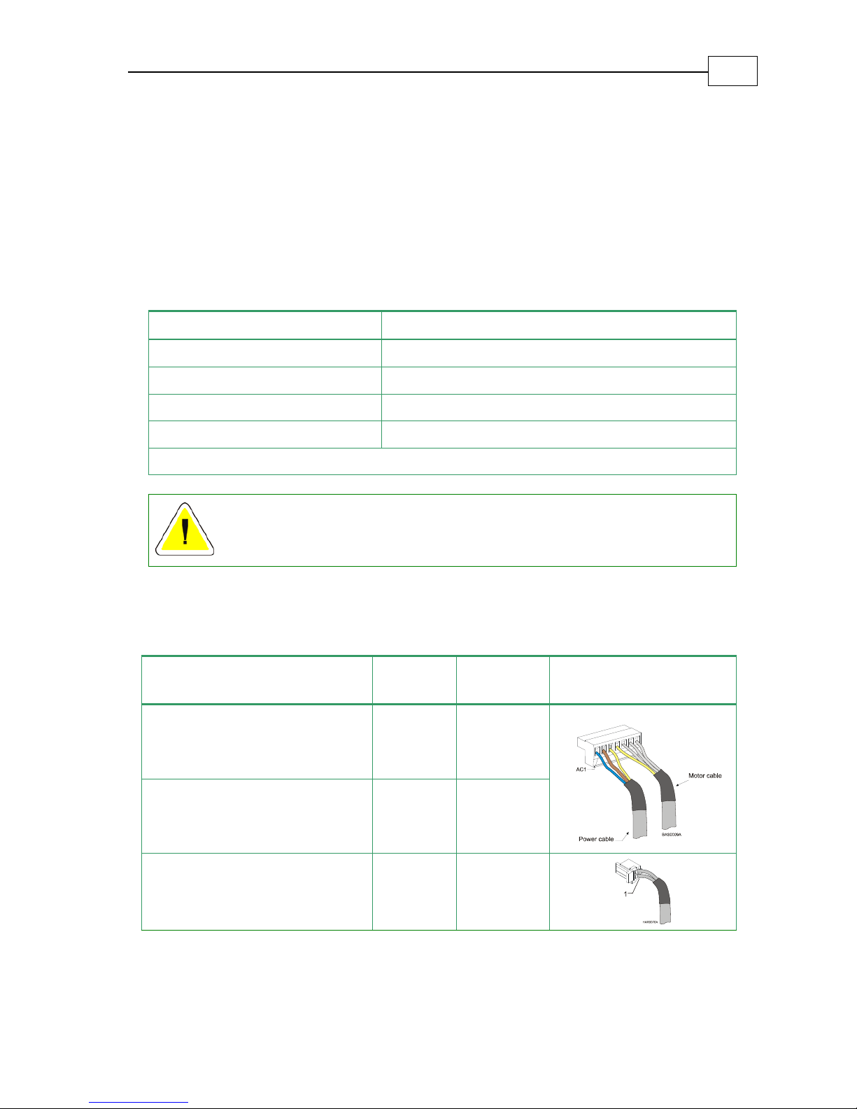
3.1.2 Hardware Requirements
The components that you will need to install your Bassoon are:
Component Connector
Described
in Section Diagram
Main Power Cable
Power
Connector
3.5.2.2
Motor Cable
Power
Connector
3.5.2.2
Auxiliary Power Cable
J4
3.5.3
Bassoon Installation Guide
MAN-BASIG (Ver 1.4)
3-1
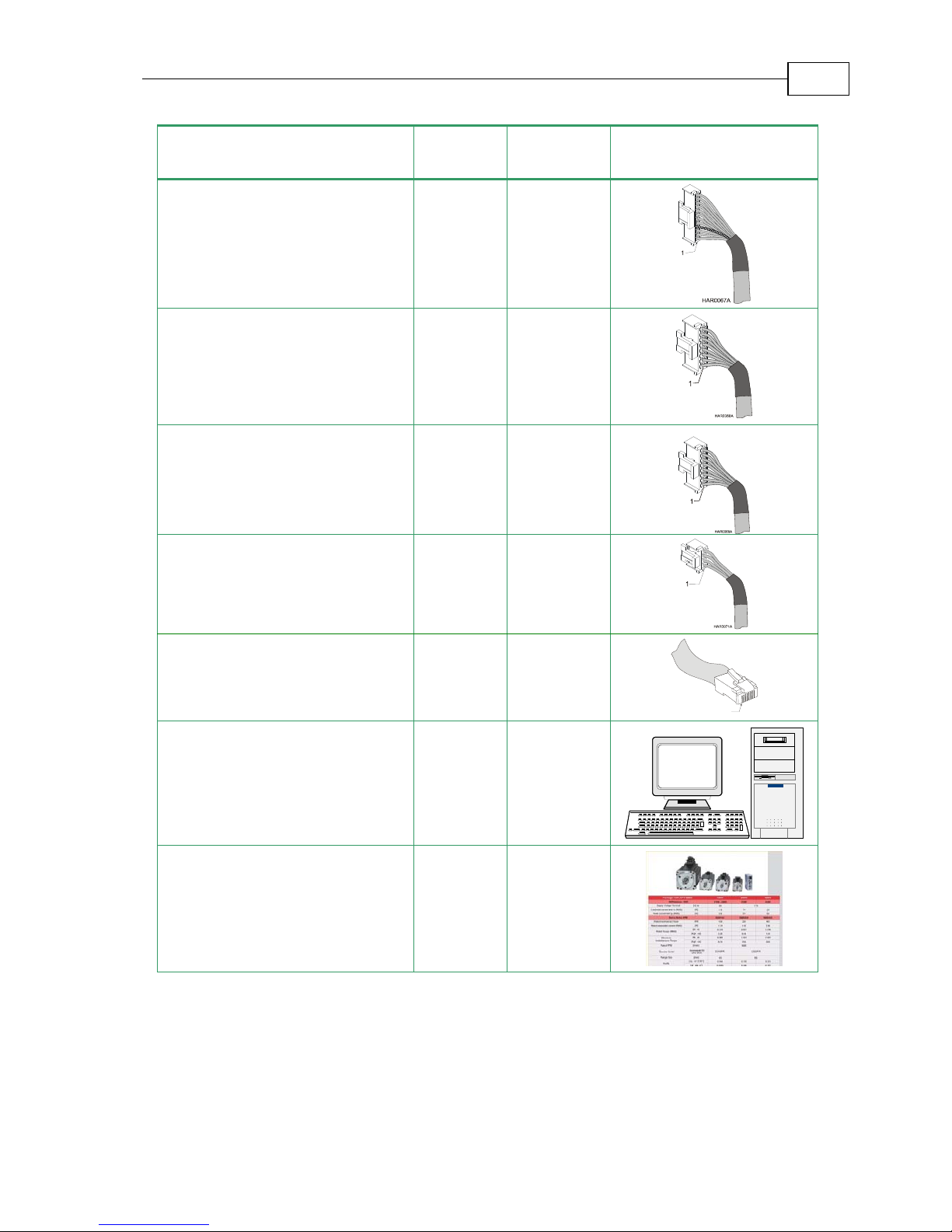
Component Connector
Described
in Section Diagram
Main Feedback Cable
J3
3.5.5
Auxiliary Feedback (if needed)
J2
3.5.6
Digital Input Cable (if needed)
J5
3.5.6
Digital Output Cable (if needed)
J6
3.5.6
Communication Cables
(RS-232 and/or CANopen)
J1, J8, J9
3.5.8
1
PC for drive setup and tuning
Motor data sheet or manual
Bassoon Installation Guide Installation
MAN-BASIG (Ver 1.4)
3-2
3.1.3 AC Power Requirements
Below are the Bassoon’s AC power requirements:
Component Single-Phase Supply Voltage
Circuit breaker current rating 200% ~ 300% of drive current
Circuit breaker voltage rating 230 VAC
Contactor Up to 200% of drive current
3.2 Unpacking the Drive Components
Before you begin working with the Bassoon system, verify that you have all of its
components, as follows:
The Bassoon servo drive
The Composer software and software manual
The Bassoon cable kit (if ordered separately)
The Bassoon is shipped in a cardboard box with styrofoam protection.
To unpack the Bassoon:
1. Carefully remove the servo drive from the box and the Styrofoam.
2. Check the drive to ensure that there is no visible damage to the instrument. If any
damage has occurred, report it immediately to the carrier that delivered your drive.
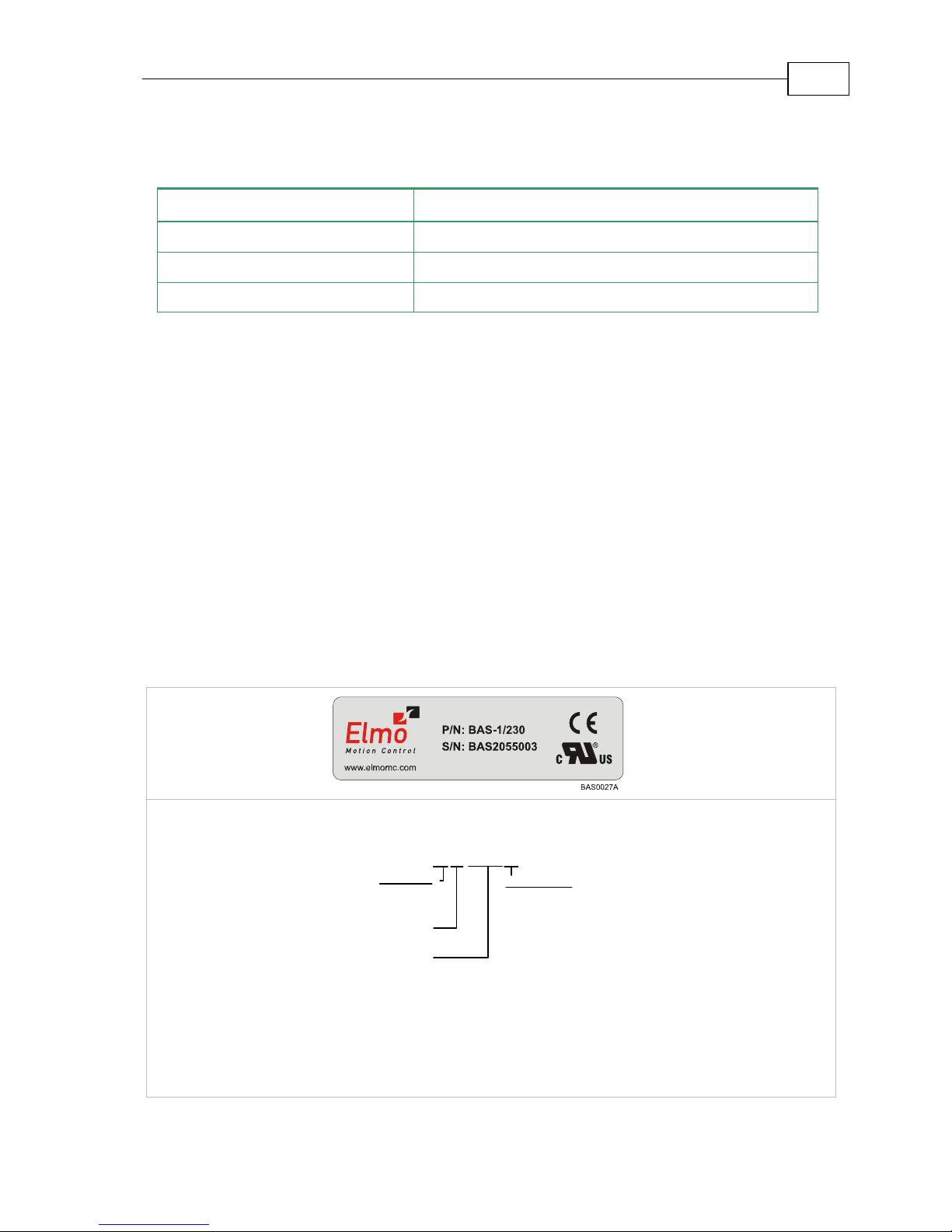
3. To ensure that the Bassoon you have unpacked is the appropriate type for your
requirements, locate the part number sticker on the side of the Bassoon. It looks like
this:
The P/N number at the top gives the type designation as follows:
Nominal AC
Operating Voltage
Continuous Current
(Amp s )
Version:
Blank = Standard
A = Advanced
Feedback:
Blank = Incremental
Encoder
and/or Halls
R=Resolver
BAS- A 1/230R
T=
Tachometer &
Potentiometer
I = Interpolated
Analog
Encoder
A=
Absolute
Encoder
S=
Stegmann
Absolute
Encoder
4. Verify that the Bassoon type is the one that you ordered.
Bassoon Installation Guide Installation
MAN-BASIG (Ver 1.4)
3-3
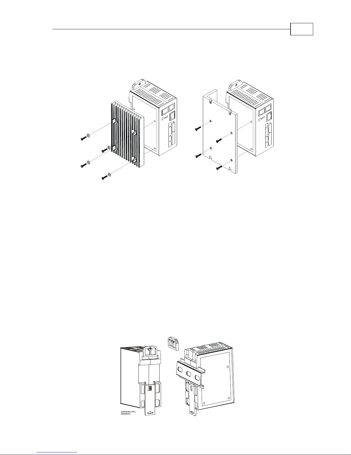
3.3 Assembling the Heatsink
When an external heatsink device is required, attach it with four screws to the left side of the
Bassoon, as depicted in the following diagrams.
BAS0033A
BAS0041A-DWG
Figure 3-1: Attaching the Heatsink
To mount the finned heatsink use M4 screws and spring washers. To mount the L-shaped
heatsink use conical head M4 screws.
3.4 Mounting the Bassoon
The Bassoon has been designed for two standard mounting options:
Mounting on a DIN rail
Attaching directly to the wall with screws
3.4.1 Mounting on a DIN Rail
At the top rear of the Bassoon, a horizontal groove lets you quickly and easily snap the drive
onto a DIN rail in your work area.
To mount the Bassoon on a DIN rail:
1. If the mounting tab is attached to the top of the Bassoon, remove it by pushing it
down and slipping it out of the slot (see the figure below).
2. Mount the upper slit on the back of the Bassoon on the upper edge of the DIN rail.
3. Tilt the bottom of the Bassoon towards the bottom of the DIN rail until you hear a
click.
Bassoon Installation Guide Installation
MAN-BASIG (Ver 1.4)
3-4

Figure 3-2: Mounting the Bassoon on a on DIN Rail
3.4.2 Mounting Directly onto a Wall
The mounting strips at the back of the Bassoon enable it to be screwed directly into a wall. If it
is not already assembled in the upper slot in the back of the Bassoon, assemble the upper
mounting tab now.
To mount the Bassoon onto a wall:
1. On the back of the drive, fully extend the top mounting strip so that the ends with the
holes are exposed. (The bottom strip is delivered already extended.)
2. Mount the Bassoon vertically onto the wall with two M4 round head screws and
washers, one through the top hole of the mounting strip and one at the bottom.
Figure 3-3: Extending the Mounting Strips and Attaching the Screws
3.5 Connecting the Cables
3.5.1 Wiring the Bassoon
Once the Bassoon is mounted, you are ready to wire the device. Proper wiring, grounding
and shielding are essential for ensuring safe, immune and optimal servo performance of the
Bassoon.
Follow these instructions to ensure safe and proper
wiring:
Use twisted-pair shielded wires for control, feedback and communication ports. For
best results, use an aluminum foil shield covered by copper braid with a drain wire.
The drain wire is a non-insulated wire that is in contact with parts of the cable,
usually the shield. It is used to terminate the shield and as a grounding connection.
Bassoon Installation Guide Installation
MAN-BASIG (Ver 1.4)
3-5
The impedance of the wire must be as low as possible. The size of the wire must be
thicker than actually required by the carrying current. 24 or 26 AWG wire for control
and feedback cables is satisfactory.
Use shielded wires for motor connections as well. If the wires are long, ensure that the
capacitance between the wires is not too high: C < 30 nF is satisfactory for most
applications.
Keep all wires and cables as short as possible.
Keep the motor wires as far away as possible from the feedback, control and
communication cables.
Ensure that in normal operating conditions, the shielded wires and drain carry no
current. The only time these conductors carry current is under abnormal conditions,
when electrical equipment has become a potential shock or fire hazard while
conducting external EMI interferences directly to ground, in order to prevent them
from affecting the drive. Failing to meet this requirement can result in
drive/controller/host failure.
After completing the wiring, carefully inspect all wires to ensure that the crimp
terminals are firmly attached to the wire ends and that the wires are firmly connected
to their connectors.
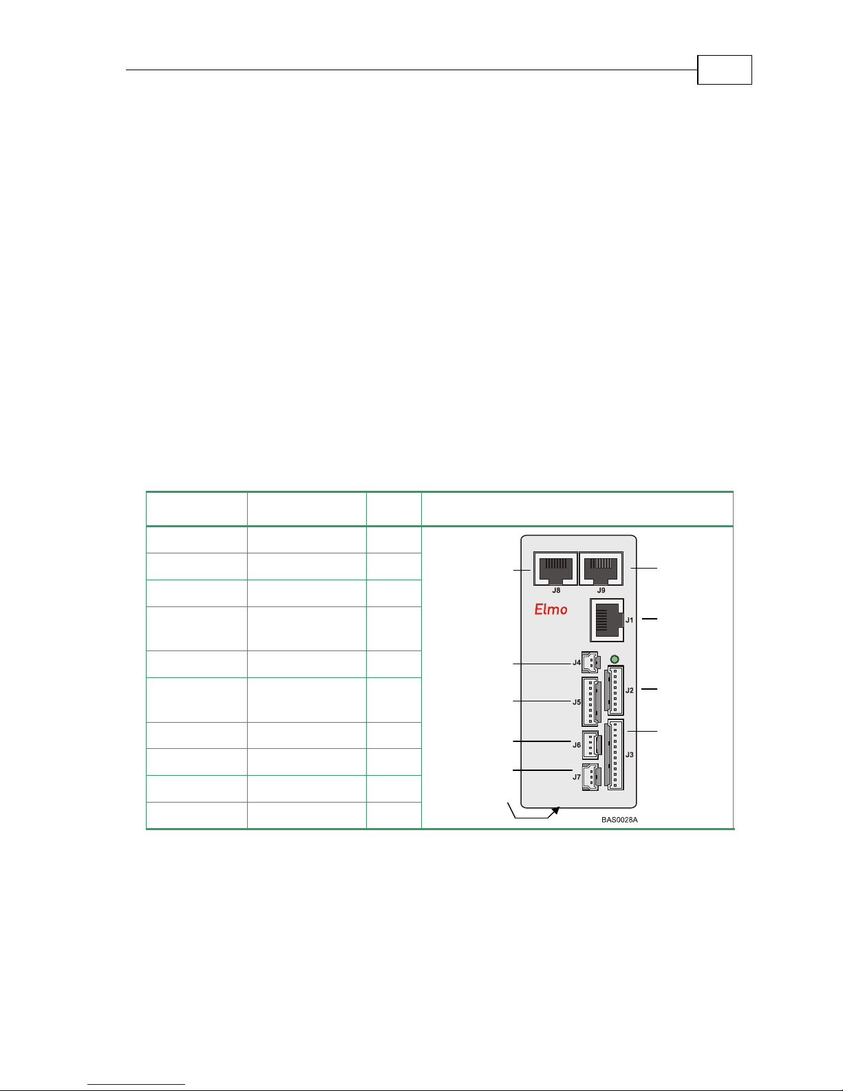
The following connectors are used for wiring the Bassoon.
Type Function Port Connector Location
8-pin RJ-45 CANopen J8
8-pin RJ-45 CANopen J9
8-pin RJ-45 RS-232 J1
8-pin Molex Auxiliary
Feedback
J2
12-pin Molex Main Feedback J3
2-pin Molex Auxiliary power
supply
J4
8-pin Molex Digital input J5
4-pin Molex Digital output J6
3-pin Molex Analog input J7
7-pin Phoenix Main power Power
Table 3-1: Bassoon Connectors
Auxiliary
Power
Supply
Digital
In
p
ut
Digital
Output
CANopen
Auxiliary
Feedback
Main
Feedback
Main
CANopen
RS232
Analog
In
p
ut
Bassoon Installation Guide Installation
MAN-BASIG (Ver 1.4)
3-6
M
M3
M2
M1
PE
AC2
PE
J4
J2
J3
Power
Connector
PC RS232
Bassoon
ANALIN1 +
ANALIN1 -
ANLRET
ANALIN1 +
ANALIN1 -
ANLRET
J7
J5
J6
IN1
IN2
IN3
IN4
IN5
IN6
INRET
INRET
OUT1
OUTRET1
OUT2
OUTRET2
Tx
Rx
COMRET
AC1
Controller
AUX.
SUPPLY 24V
DC
RS-232 J1
Feedback B
Feedback A
Main Feedback
+24v
BAS0010A
Isolated
Transformer
Drain
Wire
/ Shield
4
Drain
Wire
/ Shield
Bassoon
CAN_H
CAN_L
CAN_GND
CAN_SHLD
Drain
wire
/ Shield
CANopen J8
CAN
Controller
CAN_H
CAN_L
CAN_GND
CAN_SHLD
Drain
wire
/ Shield
CANopen J9
Bassoon Installation Guide Installation
MAN-BASIG (Ver 1.4)
3-7

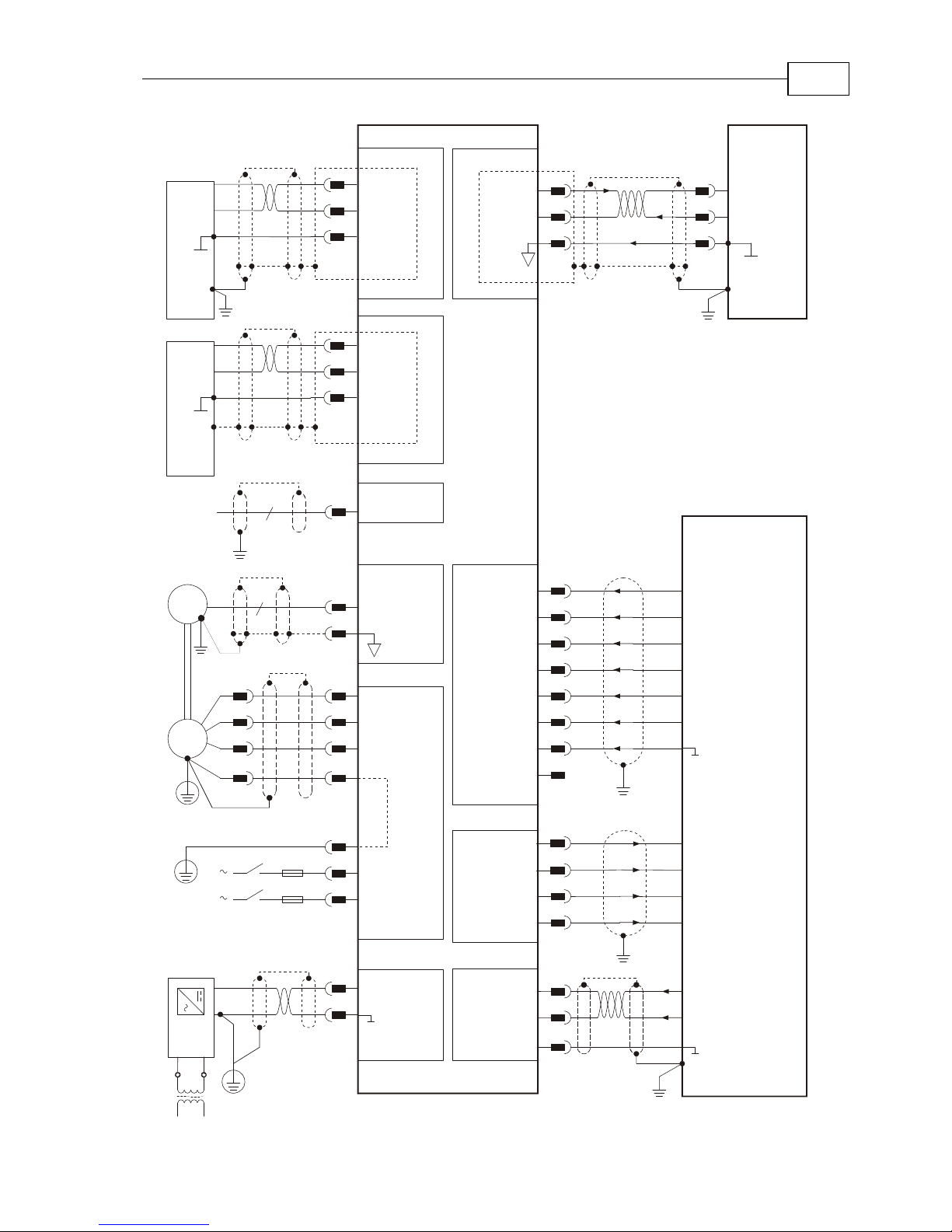
Figure 3-4: Bassoon Detailed Connection Diagram
Bassoon Installation Guide Installation
MAN-BASIG (Ver 1.4)
3-8
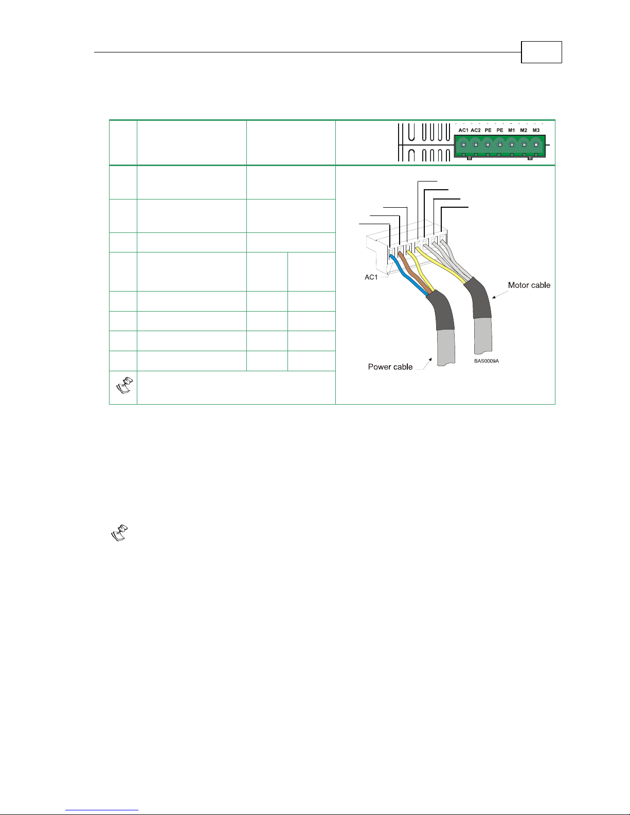
3.5.2 Connecting the Power Cables
The main power connector located at the bottom of the Bassoon, as follows:
Pin Function Cable
Pin
Positions
AC1 Main Voltage Phase 1 Power
AC2 Main Voltage Phase 2 Power
PE Protective earth Power
AC
Motor
Cable
DC
Motor
Cable
PE Protective earth Motor Motor
M1 Motor phase Motor N/C
M2 Motor phase Motor Motor
M3 Motor phase Motor Motor
When connecting several motors, all
must be wired in an identical manner.
Table 3-2: Connector for Main Power and Motor Cables
3.5.2.1 Connecting the Motor Cable
Connect the motor power cable to the M1, M2, M3 and PE terminals of the main power
connector. The phase connection order is arbitrary because the Composer will establish the
proper commutation automatically during setup. However, if you plan to copy the set-up to
other drives, then the phase order on all copy drives must be the same.
Notes for connecting the motor cables:
For best immunity, it is highly recommended to use a shielded (not twisted)
cable for the motor connection. A 4-wire shielded cable should be used. The
gauge is determined by the actual current consumption of the motor.
Connect the shield of the cable to the closest ground connection at the motor end.
The forth wire should be used for the ground connection between the motor and
the second PE terminal of the Bassoon.
Be sure that the motor chassis is properly grounded.
A
A
P
P
M
M
M
Bassoon Installation Guide Installation
MAN-BASIG (Ver 1.4)
3-9
 Loading...