

Page 1
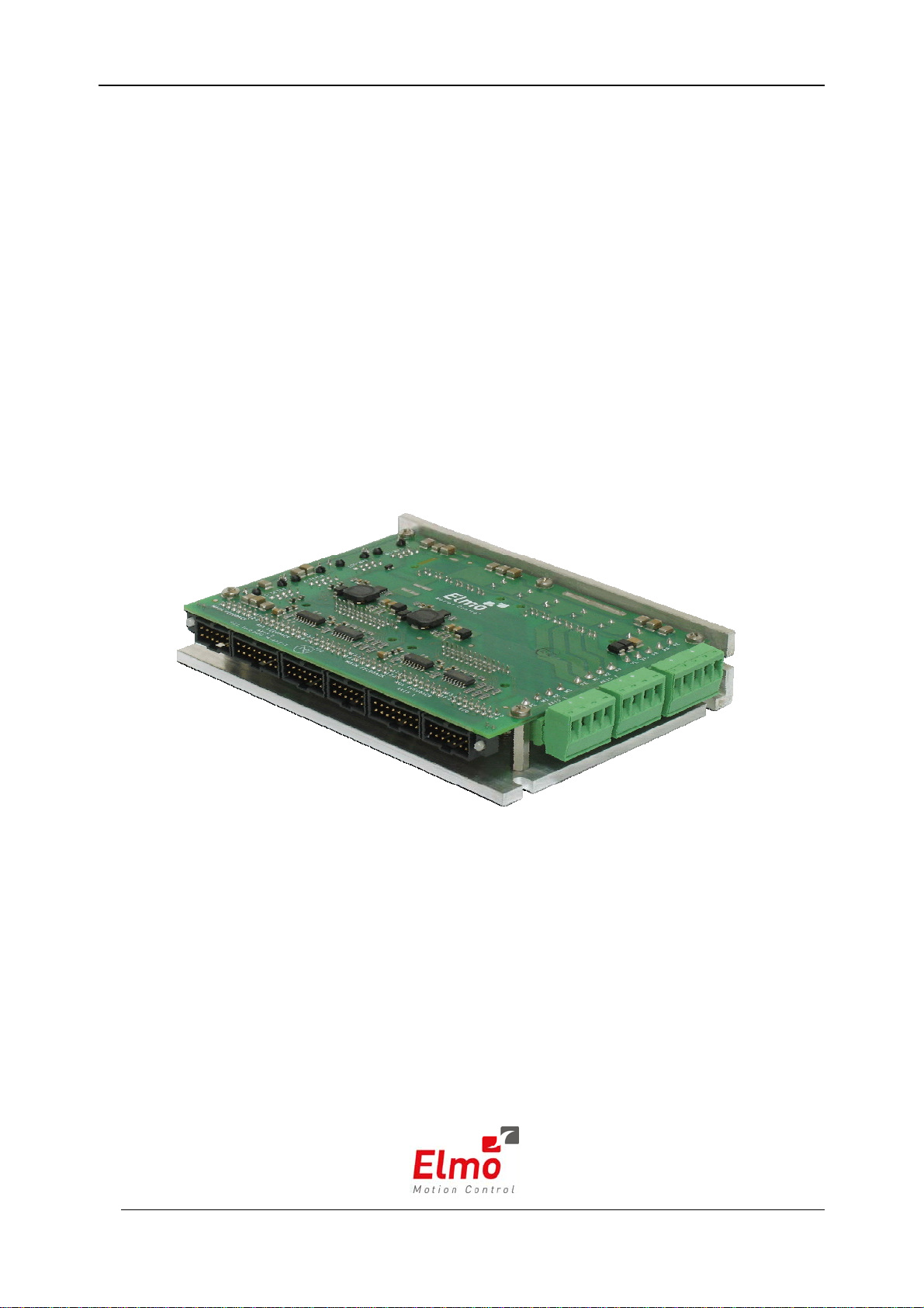
Duo
Integrated Solution
Installation Guide
June 2007 (Ver. 1.0)
Page 2
Notice
This guide is delivered subject to the following conditions and restrictions:
This guide contains proprietary information belonging to Elmo Motion Control Ltd.
Such information is supplied solely for the purpose of assisting users of the Duo in its
installation.
The text and graphics included in this manual are for the purpose of illustration and
reference only. The specifications on which they are based are subject to change
without notice.
Elmo Motion Control and the Elmo Motion Control logo are trademarks of Elmo
Motion Control Ltd.
Information in this document is subject to change without notice.
Document No. MAN-DUOIG
Copyright ©2007
Elmo Motion Control Ltd.
All rights reserved.
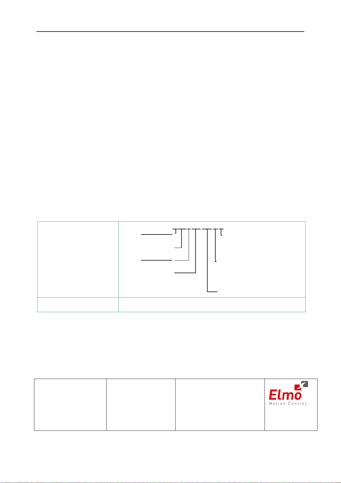
Duo Catalog Number:
DUO- A
Axis 1 Ve rs io n
Blank = Standard
A=Advanced
Continu o u s C urrent(Amps)
Axis 2 Ve rs io n
Blank = S tandard
Continu o u s C urrent(Amps)
Axis 1
A = Advanced
Axis 2
XXAXX/YYYZZ
:
:
Cable Kit Catalog No. CBL-BRDKIT-001 (kit optional)
Revision History:
Ver. 1.0 June 2007 First Release (MAN- DUOIG.PDF)
Axis 2 Feedbacks:
E- Incremental Encoder and/or Halls
R- Resolver
I- Interpolated A n a lo g E n c o de r
T- Tachometer and Potentiometer
Axis 1 Feedbacks:
E- Incremental Encoder and/or Halls
R- Resolver
I- Interpolated Analog Encoder
T- Tachometer and Potentiometer
Maximum DC
Operating Voltage
Elmo Motion Control Ltd.
64 Gisin St., P.O. Box 463
Petach Tikva 49103
Tel: +972 (3) 929-2300
Fax: +972 (3) 929-2322
Elmo Motion Control Inc.
1 Park Drive, Suite 12
Westford, MA 01886
USA
Tel: +1 (978) 399-0034
Fax: +1 (978) 399-0035
Elmo Motion Control GmbH
Steinkirchring 1
D-78056, Villingen-Schwenningen
Germany
Tel: +49 (07720) 8577-60
Fax: +49 (07720) 8577-70
www.elmomc.com
Page 3

Duo Installation Guide
MAN-DUOIG (Ver. 1.0)
Contents
i
Chapter 1: Safety Information..........................................................................................
1-1
1.1 Warnings ............................................................................................................. 1-2
1.2 Cautions............................................................................................................... 1-2
1.3 Directives and Standards................................................................................... 1-3
1.4 CE Mark Conformance....................................................................................... 1-3
1.5 Warranty Information........................................................................................ 1-3
Chapter 2: Introduction..................................................................................................... 2-1
2.1 Product Description ........................................................................................... 2-1
2.2 Product Features................................................................................................. 2-2
2.2.1 Current Control ...................................................................................................... 2-2
2.2.2 Velocity Control...................................................................................................... 2-2
2.2.3 Position Control...................................................................................................... 2-2
2.2.4 Advanced Position Control (in Advanced model only)......................................... 2-2
2.2.5 Communication Options ....................................................................................... 2-2
2.2.6 Feedback Options ................................................................................................... 2-2
2.2.7 Fault Protection....................................................................................................... 2-3
2.3 How to Use this Guide....................................................................................... 2-3
Chapter 3: Installation....................................................................................................... 3-1
3.1 Site Requirements............................................................................................... 3-1
3.2 Unpacking the Drive Components................................................................... 3-1
3.3 Mounting the Duo .............................................................................................. 3-2
3.4 Connecting the Cables ....................................................................................... 3-3
3.4.1 Wiring the Duo ....................................................................................................... 3-3
3.5 Duo Connectors type.......................................................................................... 3-5
3.6 Hardware Requirements.................................................................................... 3-6
3.7 Duo Block Diagram ............................................................................................ 3-7
3.8 The Main Power and Motor Power Connectors.............................................. 3-8
3.8.1 Connecting Motor Power ...................................................................................... 3-8
3.8.2 Connecting Main Power........................................................................................ 3-9
3.8.3 Low power Auxiliary Supply (optional)........................................................... 3-10
3.9 Main Feedback.................................................................................................. 3-12
3.10 Auxiliary Feedback (bi-directional)................................................................ 3-17
3.10.1 Main and Auxiliary Feedback Combinations................................................... 3-18
3.10.2 Auxiliary Feedback – Emulated, Differential Buffered Encoder Output Option
(YA[4]=4) ...............................................................................................................
3.10.3 Auxiliary Feedback - Differential Encoder Input Option (YA[4]=2)............. 3-22
3.10.4 Auxiliary Feedback – Differential Pulse-and-Direction Input Option (YA[4]=0)3-25
3-20
3.11 I/O….................................................................................................................. 3-27
3.11.1 Digital Input .......................................................................................................... 3-28
Page 4

Duo Installation Guide Contents
MAN-DUOIG (Ver. 1.0)
3.11.2 Digital Output....................................................................................................... 3-29
3.11.3 Analog Input ......................................................................................................... 3-29
3.12 Communications............................................................................................... 3-30
3.12.1 RS232 Communication......................................................................................... 3-30
3.12.2 CANopen Communication ................................................................................. 3-31
3.13 Powering Up ..................................................................................................... 3-33
3.14 Initializing the System...................................................................................... 3-33
Appendix A: Technical Specifications .............................................................................. A-1
A.1 Features............................................................................................................... A-1
A.2 Built-In Protection ............................................................................................. A-3
A.3 Duo Dimensions ................................................................................................ A-4
A.4 Power Ratings .................................................................................................... A-5
A.5 Control Specifications ....................................................................................... A-6
A.5.1 Current Loop...........................................................................................................A-6
A.5.2 Velocity Loop ..........................................................................................................A-7
A.5.3 Position Loop ..........................................................................................................A-7
ii
A.6 Feedbacks ........................................................................................................... A-8
A.6.1 Incremental Encoder ..............................................................................................A-8
A.6.2 Feedback Supply Voltage......................................................................................A-8
A.6.3 Digital Halls.............................................................................................................A-9
A.6.4 Interpolated Analog Encoder (Sine/Cosine) ......................................................A-9
A.6.5 Resolver..................................................................................................................A-10
A.6.6 Tachometer* ..........................................................................................................A-10
A.6.7 Potentiometer........................................................................................................A-11
A.6.8 Auxiliary Feedback Port (output mode YA[4]= 4)...........................................A-11
A.6.9 Auxiliary Feedback Port (input mode YA[4]= 2, 0).........................................A-12
A.7 I/Os..............................................................................................................…..A-13
A.7.1 Digital Input Interface – 6 Digital Inputs ..........................................................A-13
A.7.2 Digital Output Interface – 2 Digital Outputs...................................................A-14
A.7.3 Analog Inputs – 1 Analog Input..........................................................................A-14
A.8 Mechanical Specifications............................................................................... A-15
A.9 Environmental Conditions ............................................................................. A-15
A.10 Compliance Standards ............................................................................. A-15
A.10.1 Design ....................................................................................................................A-15
A.10.2 Safety ......................................................................................................................A-16
A.10.3 EMC........................................................................................................................A-16
Appendix B: Cables (Optional).........................................................................................B-1
B.1 Cable Photos........................................................................................................ B-1
B.2 Cable Kit.............................................................................................................. B-2
B.3 Main Feedback Cable (CBL-HDRFB-001) ........................................................ B-3
B.4 Auxiliary Feedback (CBL-HDRAUX-001)........................................................ B-4
Page 5

Duo Installation Guide Contents
MAN-DUOIG (Ver. 1.0)
B.5 I/O (CBL-HDRIO-001)....................................................................................... B-5
B.6 Communication Cables...................................................................................... B-6
B.6.1 RS-232 Option (CBL-RJ452321)............................................................................. B-6
B.6.2 CAN Open (CBL-RJ45CAN1) ............................................................................... B-7
B.7 Guidelines for Making Your Own Cables........................................................ B-8
B.7.1 Recommended Wire Cross Sections..................................................................... B-8
iii
Page 6
Duo Installation Guide
MAN-DUOIG (Ver. 1.0)
Chapter 1: Safety Information
In order to achieve the optimum, safe operation of the Duo, it is imperative that you
implement the safety procedures included in this installation guide. This information is
provided to protect you and to keep your work area safe when operating the Duo and
accompanying equipment.
Please read this chapter carefully before you begin the installation process.
Before you start, ensure that all system components are connected to earth ground.
Electrical safety is provided through a low-resistance earth connection.
Only qualified personnel may install, adjust, maintain and repair the servo drive.
A “qualified person” has the knowledge and authorization to perform tasks such as
transporting, assembling, installing, commissioning and operating motors.
The Duo contains electrostatic-sensitive components that can be damaged if handled
incorrectly. To prevent any electrostatic damage, avoid contact with highly insulating
materials, such as plastic film and synthetic fabrics. Place the product on a conductive
surface and ground yourself in order to discharge any possible static electricity build-up.
1-1
To avoid any potential hazards that may cause severe personal injury or damage to the
product during operation, keep all covers and cabinet doors shut.
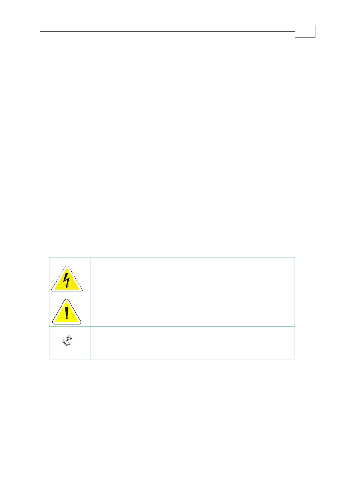
The following safety symbols are used in this manual:
Warning:
This information is needed to avoid a safety hazard, which might cause
bodily injury.
Caution:
This information is necessary for preventing damage to the product or
to other equipment.
Note:
This is auxiliary information that ensures the correct operation of the
equipment.
Page 7
Duo Installation Guide Safety Information
MAN-DUOIG (Ver. 1.0)
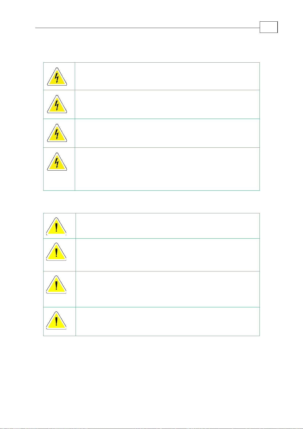
1.1 Warnings
To avoid electric arcing and hazards to personnel or electrical damage,
never connect/disconnect any plug or cable from the servo drive while
the power source is on.
Power cables can carry a high voltage, even when the motor is not in
motion. Disconnect the Duo from all voltage sources before it is opened
for servicing.
The Duo contains grounding conduits for electric current protection. Any
disruption to these conduits may cause the instrument to become hot
(live) and dangerous.
After shutting off the power and removing the power source from your
equipment, wait at least 1 minute before touching or disconnecting parts
of the equipment that are normally loaded with electrical charges (such as
capacitors or contacts). Measuring the electrical contact points with a
meter, before touching the equipment, is recommended.
1-2
1.2 Cautions
The Duo contains hot surfaces and electrically-charged components
during operation.
The maximum AC/DC power supply connected to the instrument must
comply with the parameters outlined in this guide. Furthermore, the power
supply must be isolated from hazardous live voltages using reinforced or
double insulation in accordance to approved safety standards.
When connecting the Duo to an approved 12 ~ 95VDC (8.5 ~ 67VAC)
auxiliary power supply, connect it through a line that is isolated from
hazardous live voltages using reinforced or double insulation in
accordance with approved safety standards.
Before switching on the Duo, verify that all safety precautions have been
observed and that the installation procedures in this manual have been
followed.
Page 8

Duo Installation Guide Safety Information
MAN-DUOIG (Ver. 1.0)
1.3 Directives and Standards
The Duo conforms to the following industry safety standards:
Safety Standard Item
In compliance with UL508c Power Conversion Equipment
1-3
In compliance with UL840
Insulation Coordination, Including Clearance and
Creepage Distances of Electrical Equipment
In compliance with UL60950-1
(formerly UL1950)
Safety of Information Technology Equipment,
Including Electrical Business Equipment
In compliance with EN60204-1 Low Voltage Directive, 73/23/EEC
The Duo has been developed, produced, tested and documented in accordance with the
relevant standards. Elmo Motion Control is not responsible for any deviation from the
configuration and installation described in this documentation. Furthermore, Elmo is not
responsible for the performance of new measurements or ensuring that regulatory
requirements are met.
1.4 CE Mark Conformance
The Duo is intended for incorporation in a machine or end product. The actual end
product must comply with all safety aspects of the relevant requirements of the European
Safety of Machinery Directive 98/37/EC as amended, and with those of the most recent
versions of standards EN60204-1 and EN292-2 at the least.
According to Annex III of Article 13 of Council Directive 93/68/EEC, amending Council
Directive 73/23/EEC concerning electrical equipment designed for use within certain
voltage limits, the Duo meets the provisions outlined in Council Directive 73/23/EEC.
The party responsible for ensuring that the equipment meets the limits required by EMC
regulations is the manufacturer of the end product.
1.5 Warranty Information
The products covered in this manual are warranted to be free of defects in material and
workmanship and conform to the specifications stated either within this document or in
the product catalog description. All Elmo drives are warranted for a period of 12 months
from the time of installation, or 18 months from time of shipment, whichever comes first.
No other warranties, expressed or implied — and including a warranty of
merchantability and fitness for a particular purpose — extend beyond this warranty.
Page 9

Duo Installation Guide Introduction
MAN-DUOIG (Ver. 1.0)
Chapter 2: Introduction
This installation guide describes the Duo and the steps for its wiring, installation and
power-up. Following these guidelines ensures maximum functionality of the product and
the system to which it is connected.
2.1 Product Description
The Duo series of servo drives enhances Elmo’s range of digital servo drives, recognized
for having the highest power density and intelligence. The Duo is a highly compact
integrated solution containing two drives in a single package. The solution operates
under a single power supply and is designed for applications with up to two axes.
The Duo integrates Elmo’s advanced “Elmo First Control” technology, which contributes
to the product’s excellent control performance, wide range of functionalities and high
efficiency and reliability. The solution includes two fully separated digital motion
controllers that feature:
2-1
• CANopen-based networking operating simultaneously via RS-232 and CANopen
DS 301, DSP 305, DSP 402 communications and featuring a third-generation
programming environment
• Current, velocity and position control loops including PT and PVT
• Commutation types
• Position feedbacks
The benefits are high dynamics and increased precision for dual axis automated
machines such as robots, feeders, up- and down-loaders, conveyor belts and production
lines.
Power to the various Duo models is provided by a 0 - 95VDC source. A “smart” controlsupply algorithm enables the Duo to operate with only one power supply and there is no
need for an auxiliary power supply for the logic.
If back-up functionality is required for storing control parameters in case of power-loss,
an external 12 ~ 95VDC supply should be connected (via the +VL terminal on the Duo)
providing maximum flexibility and backup functionality when needed.
Note: This back-up power supply can operate from any voltage source within the
12 ~ 95VDC range. This is much more flexible than a standard 24VDC power supply
requirement.
The Duo series fully complies with all relevant safety and EMC regulations.
Page 10

Duo Installation Guide Introduction
MAN-DUOIG (Ver. 1.0)
2.2 Product Features
2.2.1 Current Control
Fully digital
Sinusoidal commutation with vector control or trapezoidal commutation
with encoder and/or digital Hall sensors
12-bit current loop resolution
Automatic gain scheduling, to compensate for variations in the DC bus
power supply
2.2.2 Velocity Control
Fully digital
Programmable PI and FFW (feed forward) control filters
Sample rate two times current loop sample time
“On-the-fly” gain scheduling
2-2
Automatic, manual and advanced manual tuning and determination of
optimal gain and phase margins
2.2.3 Position Control
Programmable PIP control filter
Programmable notch and low-pass filters
Position follower mode for monitoring the motion of the slave axis relative
to a master axis, via an auxiliary encoder input
Pulse-and-direction inputs
Sample rate four times current loop sample time
Fast event capturing inputs
2.2.4 Advanced Position Control (in Advanced model only)
Position-based and time-based ECAM mode that supports a non-linear
follower mode, in which the motor tracks the master motion using an
ECAM table stored in flash memory
PT and PVT motion modes
Dual (position/velocity) loop
Fast output compare (OC)
2.2.5 Communication Options
Depending on the application, Duo users can select from two communication
options:
RS232 serial communication
CANopen for fast communication in a multi-axis distributed environment
2.2.6 Feedback Options
• Incremental Encoder – up to 20 Mega-Counts (5 Mega-Pulse) per second
• Digital Halls – up to 2 KHz
• Incremental Encoder with Digital Halls for commutation – up to 20 Mega-
Counts per second for encoder
Page 11

Duo Installation Guide Introduction
MAN-DUOIG (Ver. 1.0)
• Interpolated Analog Sine/Cosine Encoder – up to 250 KHz (analog signal)
Internal Interpolation - up to x4096
Automatic Correction of amplitude mismatch, phase mismatch, signals offset
Auxiliary emulated, unbuffered, single-ended, encoder output
• Resolver
Programmable 10~15 bit resolution
Up to 512 Revolution Per Second (RPS)
Auxiliary emulated, unbuffered, single-ended, encoder output
• Tachometer, Potentiometer
• Elmo drives provide supply voltage for all the feedback options
2.2.7 Fault Protection
The Duo includes built-in protection against possible fault conditions, including:
• Software error handling
• Status reporting for a large number of possible fault conditions
• Protection against conditions such as excessive temperature, under/over
voltage, loss of commutation signal, short circuits between the motor power
outputs and between each output and power input return
2-3
• Recovery from loss of commutation signals and from communication errors
2.3 How to Use this Guide
In order to install and operate your Elmo Duo, you will use this manual in conjunction
with a set of Elmo documentation. Installation is your first step; after carefully reading
the safety instructions in the first chapter, the following chapters provide you with
installation instructions as follows:
Chapter 3, Installation, provides step-by-step instructions for unpacking, mounting,
connecting and powering up the Duo.
The Appendices list all the drive ratings and specifications as well as information on the
relevant cables.
Upon completing the instructions in this guide, your Duo should be successfully
mounted and installed. From this stage, you need to consult higher-level Elmo
documentation in order to set up and fine-tune the system for optimal operation. The
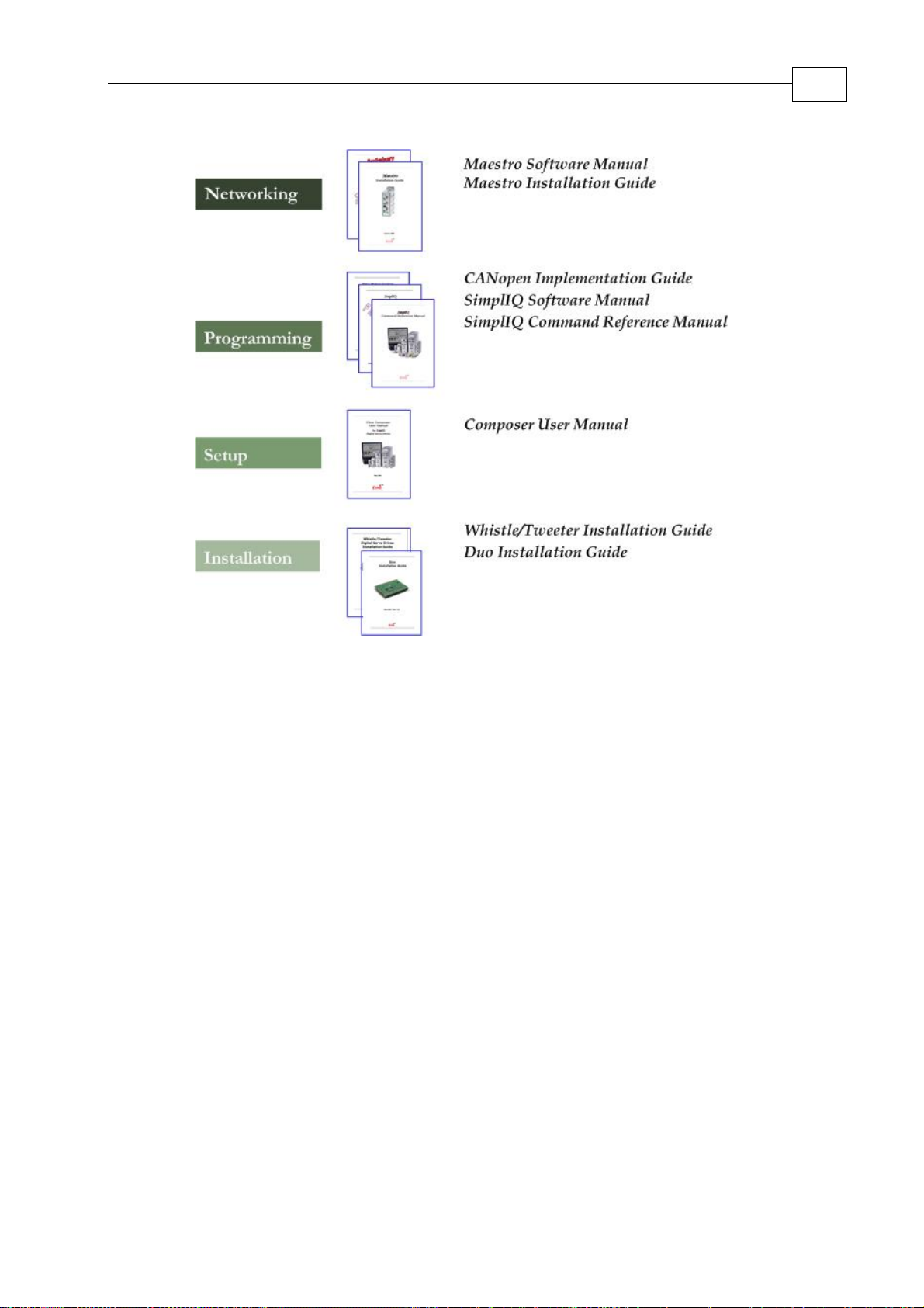
following figure describes the accompanying documentation that you will require.
Page 12
Duo Installation Guide Introduction
MAN-DUOIG (Ver. 1.0)
2-4
Figure 2-1: Elmo Digital Servo Drive Documentation Hierarchy
As depicted in the previous figure, this installation guide is an integral part of the Duo
documentation set, comprising:
The Duo Installation Guide contains information about how to use the Duo
and Cable Kit
The Composer Software Manual, which includes explanations of all the
software tools that are part of Elmo’s Composer software environment
The SimplIQ Command Reference Manual, which describes, in detail, each
software command used to manipulate the Whistle motion controllers
The SimplIQ Software Manual, which describes the comprehensive software
used with the Whistles
Page 13
Duo User Guide
MAN-DUOUG (Ver. 1.0)
Chapter 3: Installation
3.1 Site Requirements
You can guarantee the safe operation of the Duo by ensuring that it is installed in an
appropriate environment.
Feature Value
Ambient operating temperature 0° to 40°C (32° to 104°F)
Maximum operating altitude 10,000m (30,000ft)
Maximum relative humidity 90% non-condensing
Operating area atmosphere No flammable gases or vapors permitted in area
Models for extended environmental conditions are available.
3-1
The Whistle on the Duo dissipates its heat by convection. The maximum
operating ambient temperature of 0° to 40°C (32° to 104°F) must not be
exceeded. Refer to the Heat Dissipation section of the Whistle Installation Guide
for more information.
3.2 Unpacking the Drive Components
Before you begin working with the Duo, verify that you have all of its components, as
follows:
The Duo.
The Composer software and software manual.
The Duo is shipped in a cardboard box with styrofoam protection.
To unpack the Duo:
1. Carefully remove the Duo from the box and the Styrofoam.
2. Check the Duo to ensure that there is no visible damage to the instrument. If any damage
has occurred, report it immediately to the carrier that delivered your Duo.
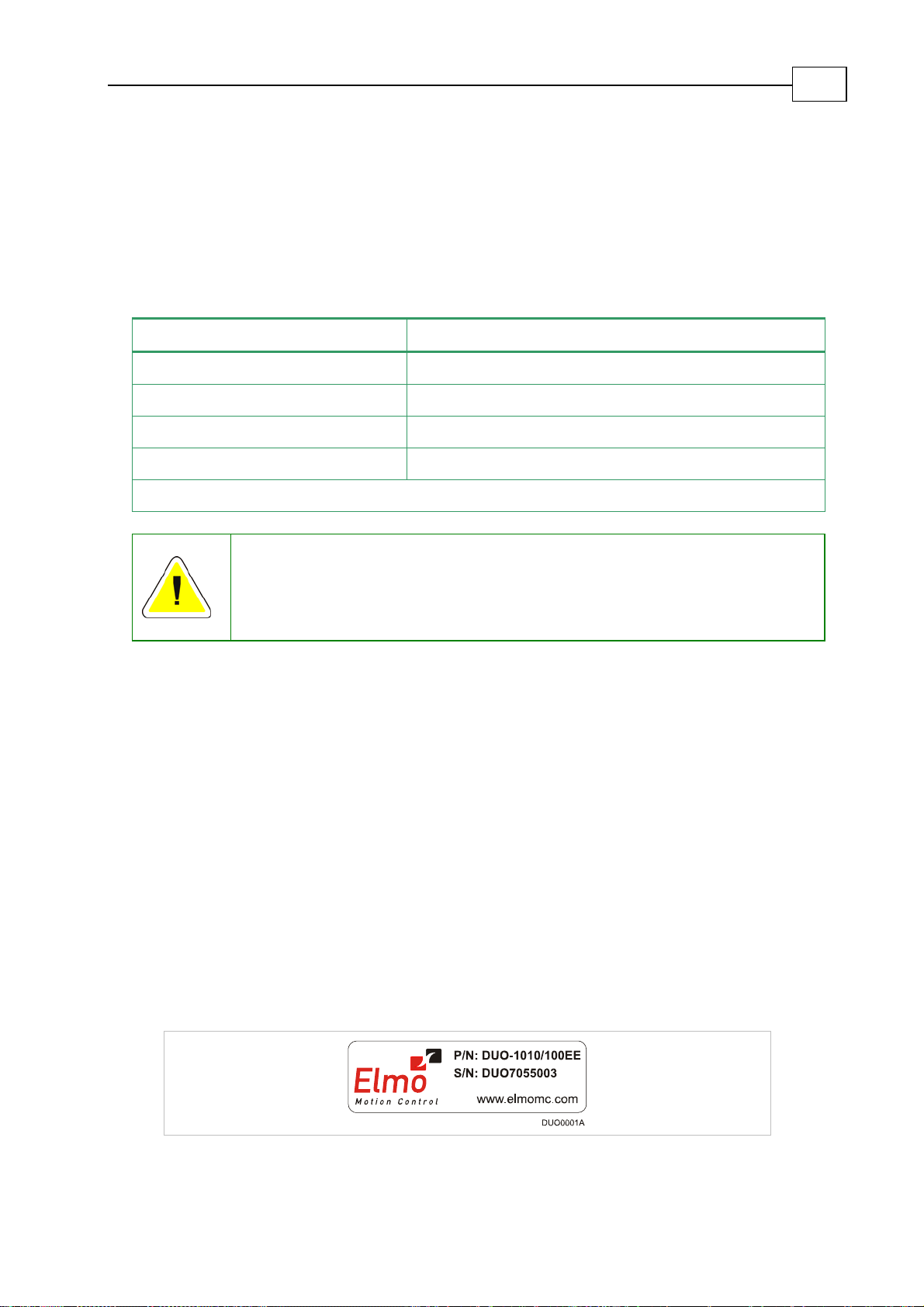
3. To ensure that the Duo you have unpacked is the appropriate type for your requirements,
locate the part number sticker on the side of the Duo. It looks like this:
Page 14
Duo User Guide
MAN-DUOUG (Ver. 1.0)
The part number at the top gives the type designation as follows:
3-2
DUO- A
Axis 1 Ve rs io n
Blank = Standard
A = Advanced
Axis 1
Continuous Current(Amps)
Axis 2 Ver s ion
Blank = Standard
A = Advanc ed
Axis 2
Continuous Current(Amps)
XXAXX/YYYZZ
:
:
Axis 2 Feedbacks:
E- Incremental Encoder and/or Halls
R- Resolver
I- Interpolated Analog Encoder
T- Tachometer and Potentiometer
Axis 1 Feedbacks:
E- Incremental Encoder and/or Halls
R- Resolver
I- Interpolated Analog Encoder
T- Tachometer and Potentiometer
Maximum DC
Operating Voltage
Verify that the Duo type is the one that you ordered, and ensure that the voltage meets your
specific requirements.
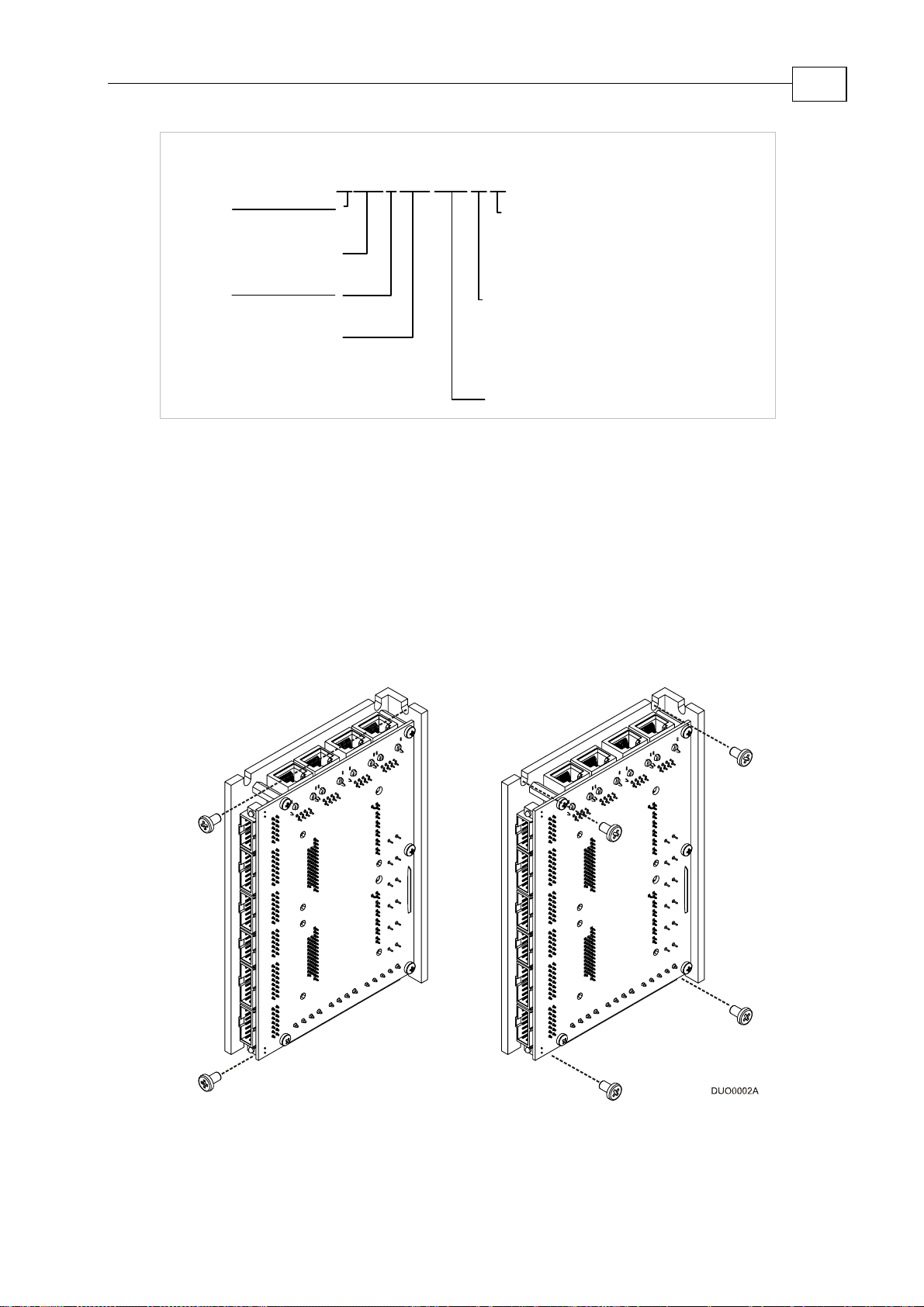
3.3 Mounting the Duo
The Duo has been designed for two standard mounting options:
“Wall Mount” along the back (can also be mounted horizontally on a metal surface)
“Book Shelf” along the side
M4 round head screws, one through each opening in the heat sink, are used to mount the Duo
(see the diagram below).
Figure
3-1: Mounting the Duo
Page 15
Duo User Guide
MAN-DUOUG (Ver. 1.0)
3.4 Connecting the Cables
3.4.1 Wiring the Duo
Once the Duo is mounted, you are ready to wire the device. Proper wiring, grounding and
shielding are essential for ensuring safe, immune and optimal servo performance of the Duo.
Follow these instructions to ensure safe and proper wiring
Use twisted pair shielded cables for control, Feedback and communication connections.
For best results, the cable should have an aluminum foil shield covered by copper braid,
and should contain a drain wire.
The drain wire is a non-insulated wire that is in contact with parts of the cable,
usually the shield. It is used to terminate the shield and as a grounding connection.
The impedance of the wire must be as low as possible. The size of the wire must be thicker
than actually required by the carrying current. A 26 or 28 AWG wire for control and
Feedback cables is satisfactory although 26 AWG is recommended.
Use shielded wires for motor connections as well. If the wires are long, ensure that the
capacitance between the wires is not too high: C < 30 nF is satisfactory for most applications.
Keep all wires and cables as short as possible.
Keep the motor wires as far away as possible from the Feedback, control and
communication cables.
Ensure that in normal operating conditions, the shielded wires and drain carry no current.
The only time these conductors carry current is under abnormal conditions, when
electrical equipment has become a potential shock or fire hazard while conducting
external EMI interferences directly to ground, in order to prevent them from affecting the
drive. Failing to meet this requirement can result in drive/controller/host failure.
After completing the wiring, carefully inspect all wires to ensure tightness, good solder
joints and general safety.
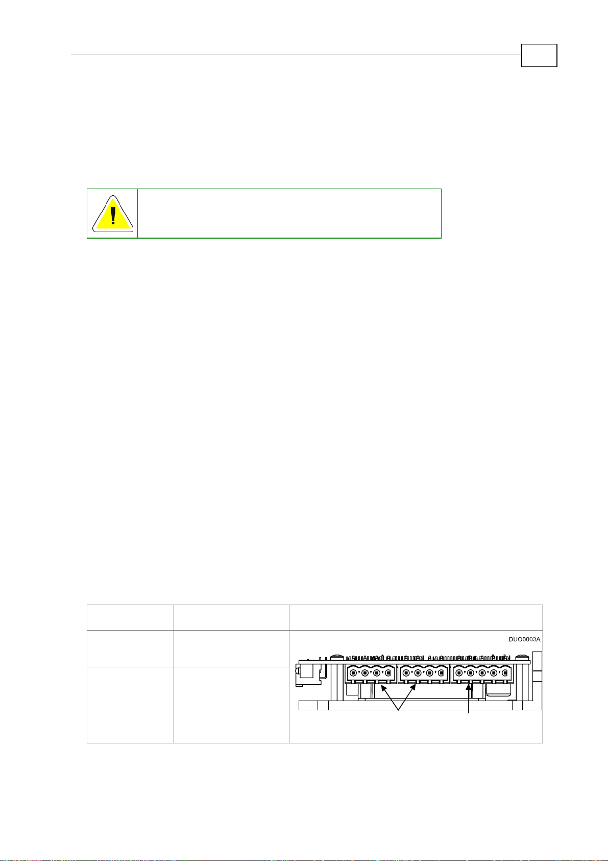
The following connectors are used for wiring the Duo:
3-3
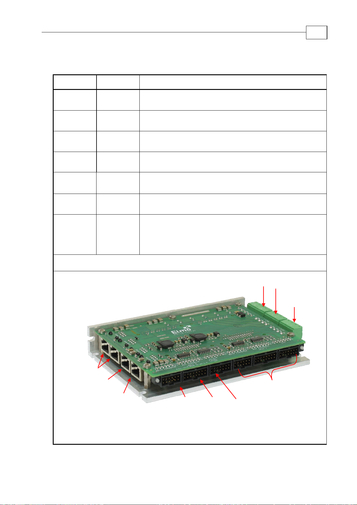
Type Function Connector Location
Main Power VL, VP+, PR, PR, PE
Motor Power PE, M1, M2, M3
Motor Main
Power
Power
Table 3-1: Connectors on the “Bottom” of the Duo
Page 16
Duo User Guide
y
y
MAN-DUOUG (Ver. 1.0)
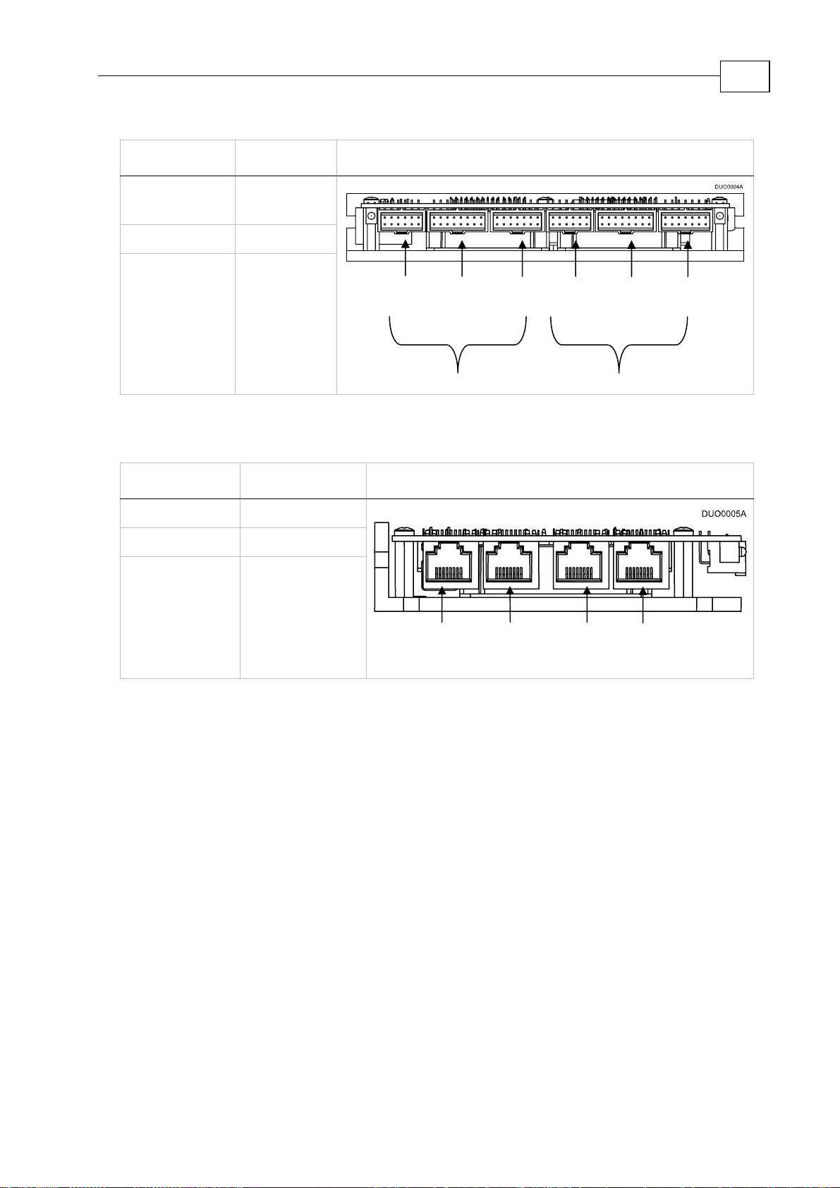
Type Function Connector Location
3-4
Main
Feedback
Feedback
I/O I/O
Auxiliary
Feedback
Auxiliary
Feedback
Main
Feedback
Table 3-2: Connectors on the “Front” of the Duo
Type Function Connector Location
CANopen CANopen IN
CANopen CANopen OUT
RS232
Auxiliar
Feedback
Axis 2
I/O
Main Auxiliar
Feedback Feedback
I/O
Axis 1
RS232-1
RS232-2
CANopen
IN
CANopen
OUT
Table 3-3: Connectors on the “Top” of the Duo
RS232-1 RS232-2
Page 17
Duo User Guide
MAN-DUOUG (Ver. 1.0)
3.5 Duo Connectors type
3-5
Type On Board Connector
Main Power Phoenix 5-pin Header P/N:MSTBA 2.5HC/5-G
Motor
Power
Main
Feedback
I/O 2
Auxiliary
Feedback
CANopen
Qty Conn.
1
2
2
Phoenix 4-pin Header P/N:MSTBA 2.5/4G-5.08
12-pin Molex Header P/N:90130-3212
14-pin Molex Header P/N:90130-3214
2
16-pin Molex Header P/N:90130-3216
2 8-pin RJ-45 Socket
Comm.
RS232
2 8-pin RJ-45 Socket
Comm.
Connector Location
CAN
RS232
Axis 2
RS232
Axis 1
Main
Feedback
Axis 2
Auxiliary
Feedback
Axis 2
Main
Power
I/O
Axis 2
Motor
Power Axis 1
Motor
Power Axis 2
Axis 1
Table 3-4: Connector Types
Page 18
Duo User Guide
MAN-DUOUG (Ver. 1.0)
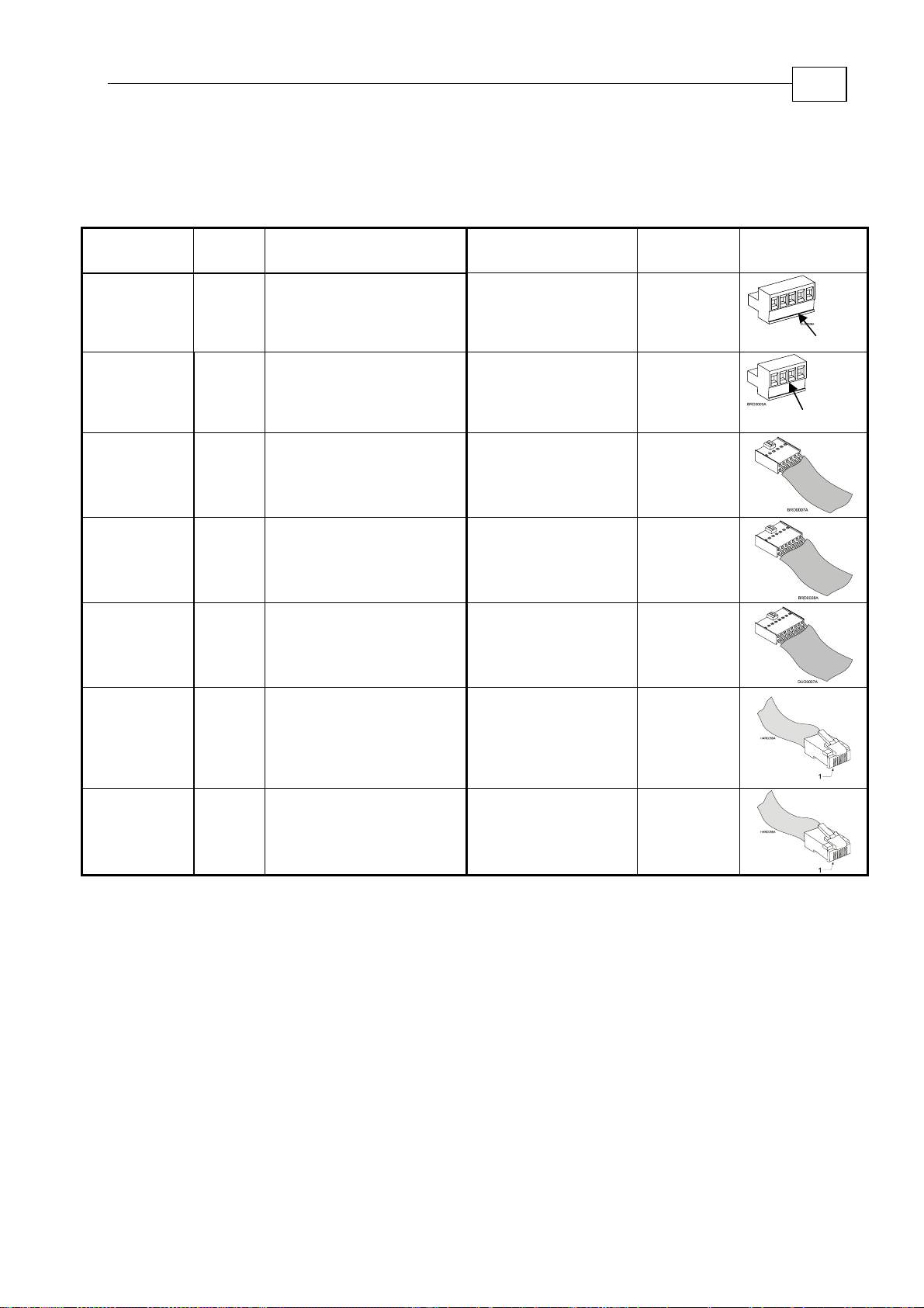
3.6 Hardware Requirements
The components that you will need to install your Duo are:
Component
Qty
Conn.
Mating Connector
Function
Described
in section
3-6
Cable
Drawing
Main Power 1
Motor
Power
Main
Feedback
2
2 B.3
I/O 2
Auxiliary
Feedback
RS232
Comm.
2
2 8-pin RJ-45 Plug B.6.1
Phoenix 5-pin Plug
P/N:MSTBT 2.5HC/5-ST
Phoenix 4-pin Plug
P/N:MSTBT 2.5/4-ST-5.08
12-pin Molex Plug
P/N:90142-0012
Pin P/N: 90119-2121
14-pin Molex Plug
P/N:90142-0014
Pin P/N: 90119-2121
16-pin Molex Plug
P/N:90142-0016
Pin P/N: 90119-2121
VL, VP+, PR, PR, PE
PE, M1, M2, M3
Feedback
I/O
B.5
Auxiliary Feedback B.4
RS232-1
RS232-2
PE
VL
Plug
PE
M3
Plug
CANopen
Comm.
CANopen IN
2 8-pin RJ-45 Plug B.6.2
CANopen OUT
Table 3-5: Connector Cross Reference
Page 19
Duo User Guide
MAN-DUOUG (Ver. 1.0)
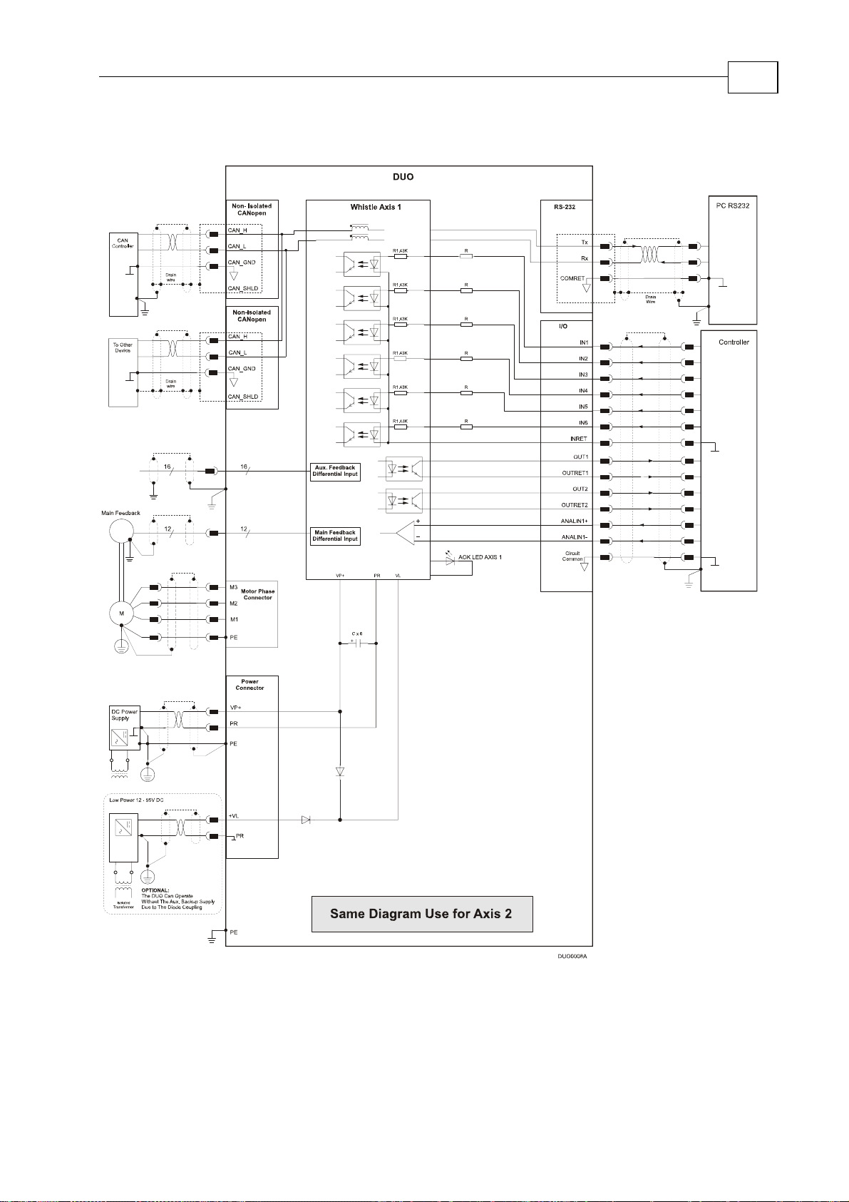
3.7 Duo Block Diagram
3-7
Figure 3-2: Duo Block Diagram
Page 20
Duo User Guide
MAN-DUOUG (Ver. 1.0)
3.8 The Main Power and Motor Power Connectors
Pin Function Cable Pin Positions
PE Protective earth Power
PR Power return Power
PR Aux. Supply Input Return Auxiliary
VP+ Pos. Power input Power
3-8
VL Aux. Supply Input Auxiliary
AC
Motor
Cable
DC
Motor
Cable
M3 Motor phase Motor Motor
M2 Motor phase Motor Motor
M1 Motor phase Motor N/C
PE Protective earth Motor Motor
Table 3-6: Connectors for Main Power and Motors
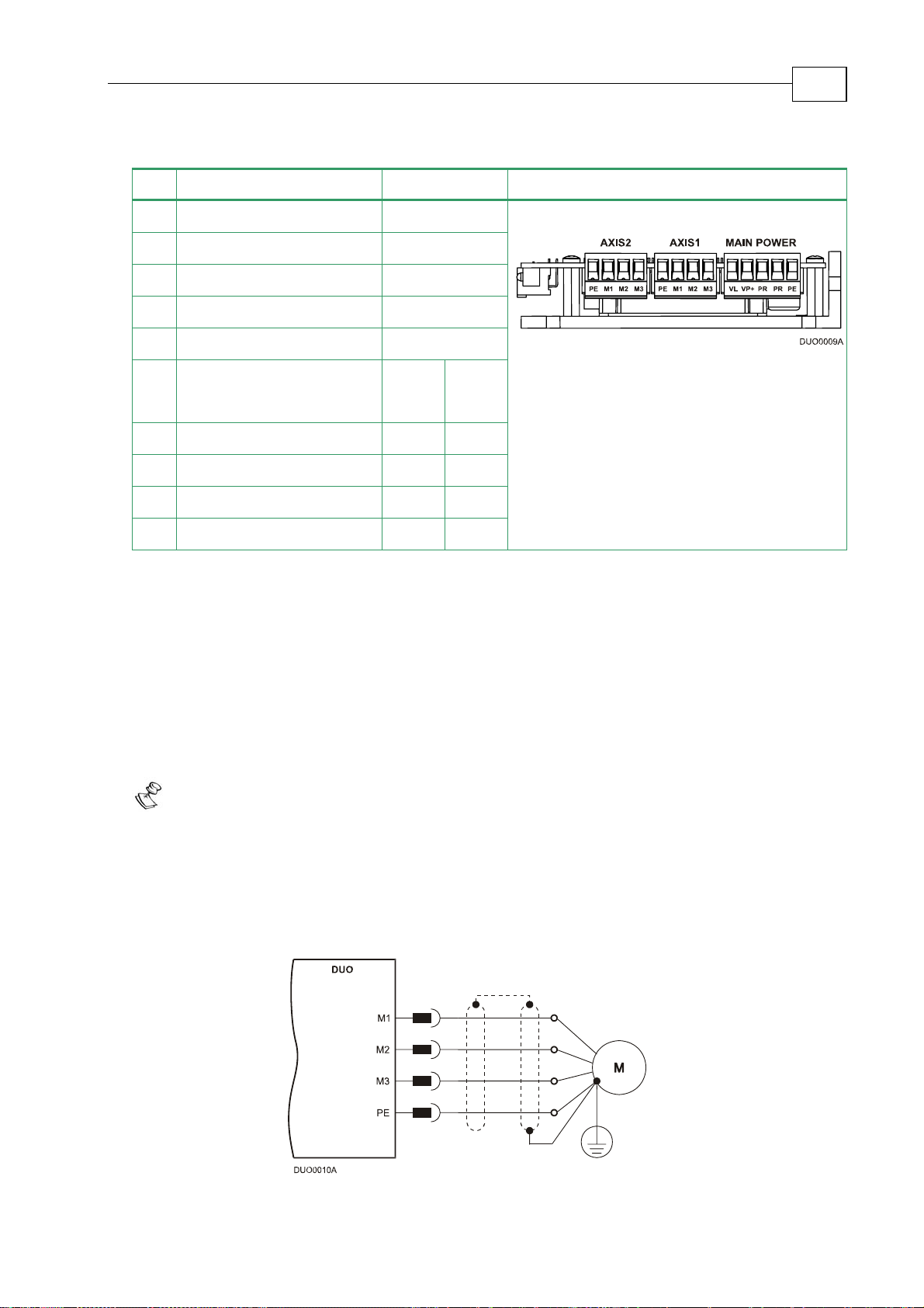
3.8.1 Connecting Motor Power
Connect the motor power cable to the M1, M2, M3 and PE terminals of the relevant axis.
The phase connection order is arbitrary because the Composer will establish the proper
commutation automatically during setup. If several motor/drive combinations are designed
to operate in an identical manner, it is recommended to download the program into all the
drives and connecting them in the same way.
Notes for connecting the motor cables:
For the greatest immunity, it is highly recommended to use a shielded (not twisted)
cable for the motor connection. A 4-wire shielded cable should be used. The gauge is
determined by the actual current consumption of the motor.
Connect the shield of the cable to the closest ground connection at the motor end.
Be sure that the motor chassis is properly grounded.
Figure 3-3: AC Motor Power Connection Diagram for each AXIS.
Page 21
Duo User Guide
MAN-DUOUG (Ver. 1.0)
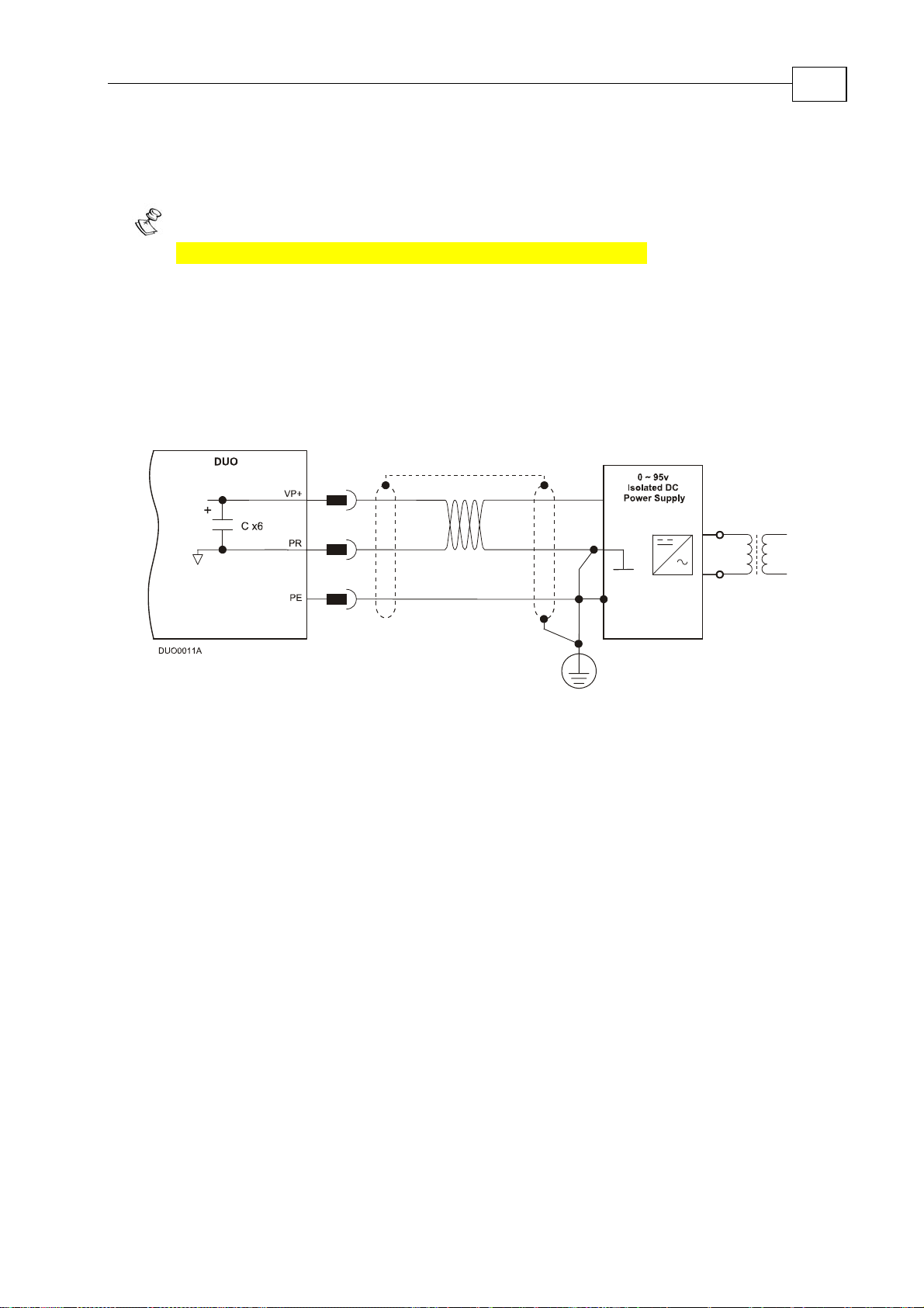
3.8.2 Connecting Main Power
Connect the DC power supply cable to the VP+ and PR terminals of the Main power connector.
Notes for connecting the DC power supply:
The source of the 0 ~ 95 VDC Power Supply must be isolated.
For the greatest immunity, it is highly recommended to use twisted and shielded
cables for the DC power supply cable. A 3-wire shielded cable should be used. The
gauge is determined by the actual current consumption of the motor.
Connect the cable shield to the closest ground connection near the power supply.
Connect the PE to the closest ground connection near the power supply.
Connect the PR to the closest ground connection near the power supply.
Before applying power, first verify the polarity of the connection.
3-9
Figure 3-4: Main Power DC Supply Connection Diagram
Page 22

Duo User Guide
MAN-DUOUG (Ver. 1.0)
3.8.3 Low power Auxiliary Supply (optional)
Notes for 12 ~ 95 VDC Auxiliary Supply connections:
The source of the 12 ~ 95 VDC Auxiliary Supply must be isolated from the Main.
the
For safety reasons, connect the return (common) of
the closest ground near the Auxiliary Supply source.
Connect the cable shield to the closest ground near the Auxiliary Supply source.
Before applying power, first verify the polarity of the connection.
Caution: Power to each Whistle and motor must come from the Main Supply
and NOT from the Auxiliary Supply.
Auxiliary Supply source to
3-10
Figure 3-5: Auxiliary Supply Connection Diagram
The back-up functionality can be used for storing control parameters in case of power-loss,
providing maximum flexibility and backup functionality when needed.
Page 23

Duo User Guide
MAN-DUOUG (Ver. 1.0)
3-11
Figure 3-6: Shared Supply Connection Diagram
Page 24

Duo User Guide
MAN-DUOUG (Ver. 1.0)
3.9 Main Feedback
The Main Feedback port is used to transfer Feedback data from the motor to the drive.
3-12
The Duo accepts the following as a
Main Feedback mechanism:
Incremental encoder only
Incremental encoder with digital hall
sensors
Digital hall sensors only
Incremental analog (sine/cosine)
encoder (option)
Resolver (option)
Tachometer and potentiometer
(option)
Analog Halls
The Main Feedback port on the Duo has a 12-pin Molex Header plug.
Interpolated Analog
Incremental Encoder
Encoder
Resolver
Tachometer and
Potentiometer
WHI XX/YYY_ WHI XX/YYYI WHI XX/YYYR WHI XX/YYYT
Pin Signal Function Signal Function Signal Function Signal Function
1 +5V Encoder/Hall
+5V supply
2 SUPRET Supply return SUPRET Supply return SUPRET Supply return SUPRET Supply return
3 CHA Channel A A+ Sine A S1 Sine A Tac 1+ Tacho Input 1
4 CHA- Channel A
complement
5 CHB Channel B B+ Cosine B S2 Cosine B Tac 2+ Tacho Input 2
6 CHB- Channel B
complement
7 INDEX Index R+ Reference R1 Vref f=1/TS,
8 INDEX- Index
complement
9 HA Hall sensor A
input
10 HB Hall sensor B
input
11 HC Hall sensor C
input
12 SUPRET Supply return SUPRET Supply return SUPRET Supply return SUPRET Supply return
+5V Encoder/Hall
+5V supply
A- Sine A
complement
B- Cosine B
complement
R- Reference
complement
HA Hall sensor A
input
HB Hall sensor B
input
HC Hall sensor C
input
+5V Encoder/Hall
S3 Sine A
S4 Cosine B
R2 Vref complement
NC - HA Hall sensor A
NC - HB Hall sensor B
NC - HC Hall sensor C
+5V supply
complement
complement
50mA Max.
f= 1/TS, 50mA
Maximum
+5V Encoder/Hall
+5V supply
Pos. (20V max)
Tac 1- Tacho Input 1
Neg. (20V max)
Pos. (50V max)
Tac 2- Tacho Input 2
Neg. (50V max)
POT Potentiometer
Input
NC -
input
input
input
Table 3-7: Main Feedback Cable Pin Assignment for Each Axis
Page 25

Duo User Guide
MAN-DUOUG (Ver. 1.0)
3-13
Figure 3-7: Main Feedback- Incremental Encoder With Digital Halls Sensors Connection Diagram
Figure 3-8: Main Feedback- Incremental Encoder Only Connection Diagram
Page 26

Duo User Guide
MAN-DUOUG (Ver. 1.0)
3-14
Figure 3-9: Main Feedback – Interpolated Analog Encoder Connection Diagram
Figure 3-10: Main Feedback– Resolver Connection Diagram
Page 27

Duo User Guide
MAN-DUOUG (Ver. 1.0)
3-15
Figure
Figure
3-11: Main Feedback – Tachometer Feedback with Digital Hall Sensor
Connection Diagram for Brushless Motors
3-12: Main Feedback – Tachometer Feedback Connection Diagram for Brush Motors
Page 28

Duo User Guide
MAN-DUOUG (Ver. 1.0)
3-16
Figure
3-13: Main Feedback – Potentiometer Feedback with Digital Hall Sensor
Connection Diagram for Brushless Motors
Figure
3-14: Main Feedback –
Potentiometer Feedback Connection Diagram for Brush Motors and Voice Coils
Page 29

Duo User Guide
MAN-DUOUG (Ver. 1.0)
3.10 Auxiliary Feedback (bi-directional)
When using one of the Auxiliary Feedback options, the relevant functionality of the Auxiliary
Feedback's ports are software selected for that option. Refer to the SimplIQ Command Reference
Manual for detailed information about Auxiliary Feedback setup.
The Auxiliary Feedback connector has two ports – B1 and B2.
• Port B1 has three pairs of differential buffered inputs
• Port B2 has three pairs of differential buffered outputs
There are two modes of operation for this interface:
• Mode 1 (Composer Command: YA[4]=4) see 3.10.2
When the Auxiliary port of the Whistle is set by the software to act as an emulated
encoder output (this is practical only when using Resolver or Analog-Encoder as the
Main Feedback):
B1 input becomes inactive
B2 presents emulated differential buffered encoder output signals of the Main
Feedback
3-17
• Mode 2 (Composer Command: YA[4]=2 or YA[4]=0) see 3.10.3 & 3.10.4
When the Auxiliary port of the Whistle is set by software to act as an input
B1 becomes an active differential buffered input
B2 presents differential buffered encoder output signals of B1
Page 30

Duo User Guide
MAN-DUOUG (Ver. 1.0)
3.10.1 Main and Auxiliary Feedback Combinations
The Main Feedback is always used in motion control devices whereas Auxiliary Feedback is
often, but not always used. The Auxiliary Feedback connector has two ports (B1 and B2).
When used in combination with Main Feedback, the Auxiliary Feedback can be set, by
software, as follows:
3-18
Main
Feedback
Incremental
Encoder
Input
Interpolated
Analog
(Sin/Cos)
Encoder
Input
Resolver
Input
Auxiliary Feedback: Output
YA[4] = 4
(Auxiliary Feedback: output)
N.A
B2 - output
Analog Encoder
position data
emulated in
Differential,
buffere d ,
incremental
Encoder format
B1 - not available
Main Feedback:
Analog Encoder
B2 - output
Resolver
position data
emulated in
differential,
buffered,
incremental
Encod e r fo rm a t
B1 - no t a v a ilable
Main Feedback:
Resolver
Potentiometer
Tachometer
Input
Typical
Applications
N.A
Analog Encoder applications where position data is required, in the Encoder’s
quadrature format, for other purposes such as position controllers and/or other
drives.
Resolver applications where position data is required in the Encoder’s quadrature
format, for other purposes such as position controllers and/or other drives.
Page 31

Duo User Guide
MAN-DUOUG (Ver. 1.0)
Auxiliary Feedback: Input
Main
Feedback
YA[4] = 2
(Auxiliary Feedback: input)
(Auxiliary Feedback: input)
YA[4] = 0
Incremental
Encoder
Input
Interpolated
Analog
(Sin/Cos)
Encoder
Input
Resolver
Input
Main
Feedback:
Incremental
Encoder
or
Analog
Encoder
or
Resolver
or
Tachometer
or
Potentiometer
Input
Auxilia ry
Feedback:
B1
Buffered
Differential
Incremental
Encoder
Input
B2
Differential
Buffered
Encoder
Output of B1
Main
Feedback:
Incremental
Encoder
or
Analog
Encoder
or
Resolver
or
Tachometer
or
Potentiometer
Input
Auxiliary
Feedback:
B2
Buffered
Differential
Pulse &
Direction
Commands
Output of B1
Potentiometer
Tachometer
Input
3-19
B1
Buffered
Differential
Pulse &
Direction
Commands
Input
Typical
Applications
Any application where two Feedbacks are
used by the drive.
The Auxiliary Feedback port serves as an
input for the Auxiliary incremental encoder.
For applications such as Follower, ECAM, or
Dual Loop.
Any application where two Feedbacks are
used by the drive.
The Auxiliary Feedback port serves as an
input for Pulse & Direction Commands.
Page 32

Duo User Guide
MAN-DUOUG (Ver. 1.0)
3.10.2 Auxiliary Feedback – Emulated, Differential Buffered Encoder Output Option (YA[4]=4)
The Auxiliary Feedback's B2 port can provide emulated encoder signals to other
controllers or drives. This option can be used when:
A Resolver or Analog Encoder is used as a Main Feedback device.
The Whistle is used as a current amplifier to provide
position data to the position controller.
The Whistle is used in velocity mode, to provide
position data to the position controller.
The Whistle is used as a master in Follower or ECAM mode.
Below are the signals on the Auxiliary Feedback ports when the Whistle Auxiliary Feedback
port is set up for emulated output of the Main Feedback device (Resolver or Analog
Incremental Encoder only).
The Auxiliary Feedback on the Duo has a 16-pin Molex Header plug.
3-20
Port Pin Signal Function
PWR 1 +5V Encoder supply voltage
PWR 2 COMRET Common return
B1 3 NA When YA[4]=4 the B1 port is not available
B1 4 NA When YA[4]=4 the B1 port is not available
B1 5 NA When YA[4]=4 the B1 port is not available
B1 6 NA When YA[4]=4 the B1 port is not available
B1 7 NA When YA[4]=4 the B1 port is not available
B1 8 NA When YA[4]=4 the B1 port is not available
B2 9 CHAO Buffered Channel A output
B2 10 CHAO- Buffered Channel A complement output
B2 11 CHBO Buffered channel B output
B2 12 CHBO- Buffered channel B complement output
B2 13 INDEXO Buffered Index output
B2 14 INDEXO- Buffered Index complement output
PWR 15 +5V Encoder supply voltage
PWR 16 COMRET Common return
Pin Position
Table 3-8: Emulated Encoder Output on the Auxiliary Feedback Port B2 - Pin Assignments
Page 33

Duo User Guide
MAN-DUOUG (Ver. 1.0)
3-21
Figure 3-15: Emulated Encoder Outputs of the Resolver or Analog Encoder -
Connection Diagram
Page 34

Duo User Guide
MAN-DUOUG (Ver. 1.0)
3-22
3.10.3 Auxiliary Feedback - Differential Encoder Input Option
(YA[4]=2)
The Whistle can be used as a slave by receiving the position data (on Port B1) of the master
encoder in Follower or ECAM mode. In this mode Port B2 provides differential buffered
Auxiliary outputs of B1 for the next slave axis in Follower or ECAM mode.
Below are the signals on the Auxiliary Feedback ports when the Whistle Auxiliary Feedback
port is set up to run as a differential Auxiliary input:
Port Pin Signal Function
PWR 1 +5V Encoder supply voltage
PWR 2 COMRET Common return
B1 3
B1 4
CHA Auxiliary channel A input
CHA- Auxiliary channel A complement input
B1 5
B1 6
B1 7
B1 8
CHB Auxiliary channel B input
CHB- Auxiliary channel B complement input
INDEX Auxiliary Index Input
INDEX- Auxiliary Index complement Input
B2 9 CHAO Buffered Channel A output
B2 10 CHAO- Buffered Channel A complement output
B2 11 CHBO Buffered channel B output
B2 12 CHBO- Buffered channel B complement output
B2 13 INDEXO Buffered Index output
B2 14 INDEXO- Buffered Index complement output
PWR 15 +5V Encoder supply voltage
PWR 16 COMRET Common return
Pin Position
Table 3-9: Differential Auxiliary Encoder Input Option along with Differential Encoder
Outputs on Auxiliary Feedback - Pin Assignments
Page 35

Duo User Guide
MAN-DUOUG (Ver. 1.0)
Figure 3-6: Differential Auxiliary Input Option - Block Diagram
3-23
Page 36

Duo User Guide
MAN-DUOUG (Ver. 1.0)
3-24
Figure 3-16: Differential Auxiliary Input Option on Auxiliary Feedback - Connection Diagram
Page 37

Duo User Guide
MAN-DUOUG (Ver. 1.0)
3.10.4 Auxiliary Feedback – Differential Pulse-and-Direction
Input Option (YA[4]=0)
This mode is used for input of differential pulse-and-direction position commands on Port B1.
In this mode Port B2 provides differential buffered pulse-and-direction outputs of B1 for
another axis.
Below are the signals on the Auxiliary Feedback ports when set up to run as a differential
pulse-and-direction input:
Port Pin Signal Function
PWR 1 +5V Encoder supply voltage
PWR 2 COMRET Common return
B1 3
B1 4
CHA Auxiliary Pulse input
CHA- Auxiliary Pulse complement input
3-25
B1 5
B1 6
CHB Auxiliary Direction input
CHB- Auxiliary Direction complement input
B1 7 NA Do not connect this pin
B1 8 NA Do not connect this pin
B2 9 CHAO Buffered Pulse output
B2 10 CHAO- Buffered Pulse complement output
B2 11 CHBO Buffered Direction output
B2 12 CHBO- Buffered Direction complement output
B2 13 NA Do not connect this pin
B2 14 NA Do not connect this pin
PWR 15 +5V Encoder supply voltage
PWR 16 COMRET Common return
Pin Position
Table 3-10: Pulse-and-Direction Pin Assignment on Auxiliary Feedback
Page 38

Duo User Guide
MAN-DUOUG (Ver. 1.0)
3-26
Figure 3-17: Pulse-and-Direction Input Option on Auxiliary Feedback - Connection Diagram
Page 39

Duo User Guide
MAN-DUOUG (Ver. 1.0)
3.11 I/O
Each Whistle on the Duo has 6 digital inputs, 2 digital outputs and a single analog input.
3-27
The I/O port has a
14-pin Molex Header plug with the following pin-outs.
Pin Signal Function
1 OUT1 Programmable Digital output 1
2 OUTRET1 Programmable Digital output 1 return
3 OUT2 Programmable Digital output 2
4 OUTRET2 Programmable Digital output 2 return
5 IN1 Programmable Digital input 1
6 IN2 Programmable Digital input 2
7 IN3 Programmable Digital input 3
8 IN4 Programmable Digital input 4
9 IN5 Programmable Digital input 5
10 IN6 Programmable Digital input 6
11 INRET Programmable Digital input return
12 COMRET Common return
13 ANALIN1+ Analog input 1+
14 ANALIN1- Analog input 1-
Pin Position
Table 3-11: I/O Port and Cable - Pin Assignment for Each Axis
Page 40

Duo User Guide
MAN-DUOUG (Ver. 1.0)
3.11.1 Digital Input
The Default Digital Input level Signal is set to 24v (PLC).
Note: 5v is also available (TTL).
3-28
Figure 3-18: Digital Input Connection Diagram
Page 41

Duo User Guide
MAN-DUOUG (Ver. 1.0)
3.11.2 Digital Output
3-29
Figure 3-19: Digital Output Connection Diagram
3.11.3 Analog Input
Figure 3-20: Analog Input with Single-ended Source
Page 42

Duo User Guide
MAN-DUOUG (Ver. 1.0)
3.12 Communications
The communication cables use an 8-pin RJ-45 plug that connect to the RS232 and CANopen
ports on the Duo.
The communication interface may differ according to the user’s hardware. The Duo can
communicate using the following options:
1. RS232, full duplex
2. CANopen
RS232 communication requires a standard, commercial 3-core null-modem cable connected
from the Duo to a serial interface on the PC. The interface is selected and set up in the
Composer software.
In order to benefit from CANopen communication, the user must have an understanding of
the basic programming and timing issues of a CANopen network.
For ease of setup and diagnostics of CAN communication, RS232 and CANopen can be used
simultaneously.
3-30
3.12.1 RS232 Communication
Notes for connecting the RS232 communication cable:
Connect the shield to the ground of the host (PC). Usually, this connection is
soldered internally inside the connector at the PC end. You can use the drain wire to
facilitate connection.
The RS232 communication port is non-isolated.
The male RJ plug must have a shield cover.
Ensure that the shield of the cable is connected to the shield of the RJ plug.
The drain wire can be used to facilitate the connection.
Pin Signal Function Pin Position
1 — —
2 — —
3 Tx RS232 transmit
4 — —
5 COMRET Communication return
6 Rx RS232 receive
RS-232
7 — —
8 — —
body Drain Wire
shield
Table 3-12: RS232 Cable - Pin Assignments
Page 43

Duo User Guide
MAN-DUOUG (Ver. 1.0)
Figure 3-21: RS232 Connection Diagram
3-31
3.12.2 CANopen Communication
Notes for connecting the CANopen communication cable:
Use 26 or 28 AWG twisted pair shielded cables. For best results, the shield
should have aluminum foil and be covered by copper braid with a drain wire
Connect the shield to the ground of the host (PC). Usually, this connection is
soldered internally inside the connector at the PC end. You can use the drain wire to
facilitate connection.
The CANopen communication port is non-isolated.
The male RJ plug must have a shield cover.
Ensure that the shield of the cable is connected to the shield of the RJ plug.
The drain wire can be used to facilitate the connection.
For "daisy-chain" connections, connect a termination 120-ohm resistor at each of the
two ends of the network cable.
Pin Signal Function Pin Position
1 CAN_H CAN_H busline (dominant high)
2 CAN_L CAN_L busline (dominant low)
3 CAN_GND CAN ground
4 — —
CAN
5 — —
6 CAN_SHLD Shield, connected to the RJ plug cover
7 CAN_GND CAN Ground
8 — —
body Drain Wire
shield
Table 3-13: CANopen Cable - Pin Assignments
Page 44

Duo User Guide
MAN-DUOUG (Ver. 1.0)
3-32
Figure 3-22: CANopen Network Connection Diagram
Caution:
When installing CANopen
communications, ensure
that each servo drive is
allocated a unique ID.
Otherwise, the CANopen
network may hang.
Page 45

Duo User Guide
MAN-DUOUG (Ver. 1.0)
3.13 Powering Up
After the cables have been connected to their devices, the Duo is ready to be powered up.
Caution:
Before applying power, ensure that the DC supply is within the specified range and
that the proper plus-minus connections are in order.
3.14 Initializing the System
After the Duo has been connected and mounted, the system must be set up and initialized.
This is accomplished using the Composer, Elmo’s Windows-based software application. Install
the application and then perform setup and initialization according to the directions in the
Composer Software Manual.
3-33
Page 46

Duo Installation Guide
Appendix A: Technical Specifications
A.1 Features
• Operating power
o DC power supply: 12 - 95 VDC source
• DC BUS
o DC power supply
• Control supply
o A separate DC power supply 12 - 95 VDC serves as both the auxiliary supply
and the backup supply (Option)
• Operating modes
A-1
o Current, velocity and position
• Commutation alternatives
o Sinusoidal vector control
o Trapezoidal
o DC brush
• Feedback alternatives
o Incremental encoder + digital Halls
o Incremental encoder only
o Digital Halls
o Resolver
o Sin / Cos
o Sin / Cos+Digital Halls
o Analog Halls
o Tacho
o Potentiometer
• Communication
o Simultaneous operation of RS-232 and CANopen DS 402 User programming
• User Programming
o Third-generation programming environment (language and Elmo Studio)
• Encoder Inputs
o Two
• Event capturing inputs
Page 47

Duo Installation Guide
MAN-DUOIG (Ver. 1.0)
• Event triggered programming structure
• Analog inputs
o 1 differential inputs with 12-bit resolution
• Enable input, limit switches and emergency stop handling
• Smart multi-purpose inputs
o Programmable as Enable, Forward and Reverse Limit Switches, Home,
Capture
• Uncommitted programmable inputs
o 6 Inputs sharing one single common
• Uncommitted, programmable outputs
o 2 separated outputs
A-2
• Storage memory
o Large, non-volatile storage of controller parameters and user programs
• Setup, startup and tuning software
o Windows-based Composer
• Automatic analysis of kinematics
• Status indication
o Bi-color LED
• Automatic procedures
o Commutation alignment
o Phase sequencing
o Current loop offset adjustment
o Current loop gain tuning
o Current gain scheduling
o Velocity loop offset adjustment
o Velocity gain tuning
o Velocity gain scheduling
o Position gain tuning
• Motion modes
o Point-to-point (PTP)
o Jogging
o Position-Velocity-Time (PVT)
o
Position-Time (PT)
o Pulse-and-direction
Page 48

Duo Installation Guide
MAN-DUOIG (Ver. 1.0)
A.2 Built-In Protection
• Software error handling
o Software-based
• Status reporting
o Available for a large number of fault conditions
• Protection against:
o Short circuit between motor power outputs
o Short circuit between each motor power output and DC bus return
o Failure of internal power supply
o Heatsink over-temperature
o Under/over voltage
A-3
o Loss of commutation signals
o Loss of velocity feedback
o “Bad” commutation
o Communication error
Page 49

Duo Installation Guide
MAN-DUOIG (Ver. 1.0)
A.3 Duo Dimensions
A-4
Page 50

Duo Installation Guide
MAN-DUOIG (Ver. 1.0)
A.4 Power Ratings
Feature Unit 1/60 2.5/60 5/60 10/60 15/60 1/100
Minimum supply voltage VDC 8.5 12
Nominal supply voltage VDC 48 85
Maximum supply voltage VDC 59 95
2.5/100
5/100 10/100 15/100
A-5
Max. output power from
the drive without heatsink
W 50 120 240 480 720 75 180 400 800 1200
Efficiency at rate power % > 99
Output Voltage % > 95% of supply VDC at f=22 KHz
DC and Trapezoidal
Commutation Continuous
A 1 2.5 5 10 15 1 2.5 5 10 15
Current Limit (Ic)
Sinusoidal Commutation
Continuous RMS Current
A 0.7 1.8 3.6 7 10.7 0.7 1.8 3.6 7 10.7
Limit (Ic)
Peak current limit (RMS) A 2 x Ic
PWM Switching
Frequency
KHz 22 +/-5% default on the motor
Switching Method Advanced Unipolar PWM
Notes:
Current rating:
The current ratings of the Duo are given in units of DC amperes (ratings that
are used for trapezoidal commutation or DC motors). The RMS (sinusoidal
commutation) value is the DC value divided by 1.41.
Page 51

Duo Installation Guide
MAN-DUOIG (Ver. 1.0)
A.5 Control Specifications
A.5.1 Current Loop
Feature Details
Controller type Vector, digital
A-6
Current sampling time
70 - 100 μsec
Current loop bandwidth 1400 - 2500 Hz
Compensation for bus voltage
Gain scheduling
variations
Motor types
AC brushless (sinusoidal)
DC brushless (trapezoidal)
DC brush
Linear brushless motor
Current control Fully digital
Sinusoidal with vector control
Programmable PI control filter based on a pair of
PI controls of AC current signals and constant
power at high speed
Current loop step response
300 - 400 μsec
(including settling time)
Current rise time
150 - 200 μsec
Page 52

Duo Installation Guide
MAN-DUOIG (Ver. 1.0)
A.5.2 Velocity Loop
Feature Details
Controller type PI
Speed sampling time 140 - 200 μsec ( x2 current loop sample time)
Velocity loop bandwidth
Velocity control Fully digital
Programmable PI and FFW control filters
On-the-fly gain scheduling
Automatic, manual and advanced manual tuning
A-7
Velocity and position feedback
options
Incremental encoder + digital Halls
Incremental encoder only
Digital Halls
Resolver
Sin / Cos
Sin / Cos+ Digital Halls
Analog Halls
Tacho
Potentiometer
Note: With all feedback options, 1/T with automatic
mode switching is activated (gap, frequency and
derivative).
Velocity command options Analog
Internally calculated by either jogging or step
Note: All software-calculated profiles support
on-the-fly changes.
A.5.3 Position Loop
Feature Details
Controller type 124 PIP
Position sampling time 280 - 400 μsec ( x 4 current loop sample time)
Analog input command
12-bit inputs
resolution
PWM resolution 12-bit
PWM switching frequency on
2/ Ts (factory default 22 kHz on the motor)
the load
Control inputs PLC or +5V level
Page 53

Duo Installation Guide
MAN-DUOIG (Ver. 1.0)
A.6 Feedbacks
A.6.1 Incremental Encoder
Feature Details
A-8
Encoder format
A, B and Index
Differential
Quadrature
Interface: RS-422
Input resistance: Differential: 120 Ω
Maximum incremental encoder
frequency:
Minimum quadrature input
period (P
IN)
Minimum quadrature input
high/low period (P
HL)
Minimum quadrature phase
period (P
PH)
Maximum encoder input voltage
range
Maximum absolute: 5 MHz single,
20 MHz quadrature
112 nsec
56 nsec
28 ns
Common mode: ±7V
Differential mode: ±7V
A.6.2 Feedback Supply Voltage
Feature Details
Encoder/Hall supply voltage 5V +5%
Maximum encoder supply current 200 mA (For the main encoder only)
Page 54

Duo Installation Guide
MAN-DUOIG (Ver. 1.0)
A.6.3 Digital Halls
Feature Details
Halls inputs HA, HB, HC.
Single ended inputs
Built in hysteresis for noise immunity.
A-9
Input voltage Nominal operating range: 0V < V
Maximum absolute: -1V < V
High level input voltage: V
Low level input voltage: V
In_Hall
InHigh
InLow
In_Hall
< 15V
> 2.5V
< 1V
Input current Sink current (when input pulled to the
common): 3ma
Source current: 1.5 ma (designed to also
support open collector Halls)
Maximum frequency f
MAX
: 2 kHz
A.6.4 Interpolated Analog Encoder (Sine/Cosine)
Feature Details
Analog encoder format
Analog input signal level
Input resistance Differential 120 Ω
Maximum analog signal frequency f
Sine and Cosine signals
Offset voltage: 2.2 V – 2.8 V
Differential, 1 V peak to peak
: 250 kHz
MAX
< 5V
Interpolation multipliers Programmable: x4 to x4096
Maximum “counts” frequency 80 mega-counts/sec "internally"
Automatic errors correction
Signal amplitudes mismatch
Signal phase shift
Signal offsets
Page 55

Duo Installation Guide
MAN-DUOIG (Ver. 1.0)
A.6.5 Resolver
Feature Details
Resolver format Sine/Cosine
Differential
Input resistance Differential 2.49 KΩ
Resolution Programmable: 10 ~ 15 bits
Maximum electrical frequency (RPS) 512 revolutions/sec
Resolver transfer ratio 0.5
Reference frequency 1/Ts (Ts = sample time in seconds)
Reference voltage Supplied by the Whistle
A-10
Reference current
Up to ±50 mA
A.6.6 Tachometer*
Feature Details
Tachometer format Differential
Maximum operating differential
voltage for TAC1+, TAC1-
Maximum absolute differential input
voltage for TAC1+, TAC1-
Maximum operating differential
voltage for TAC2+, TAC2-
Maximum absolute differential input
voltage for TAC2+, TAC2-
Input resistance for TAC1+, TAC1- 46 KΩ
Input resistance for TAC2+, TAC2- 100 KΩ
Resolution 14 bit
+/- 20V
+/-25V
+/- 50V
+/- 60V
* Only one Tachometer port can be used at a time (either TAC1+/TAC1- or TAC2+/TAC2-).
TAC1+/TAC1- is used in applications with having a Tachometer of less than 20V.
TAC2+/TAC2- is used in applications with having a Tachometer of between 20V and 50V.
Page 56

Duo Installation Guide
MAN-DUOIG (Ver. 1.0)
A.6.7 Potentiometer
Feature Details
Potentiometer Format Single-ended
Operating Voltage Range 0 ~ 5V supplied by the Whistle
Potentiometer Resistance 100Ω ~ 1 KΩ … above this range, linearity is
affected detrimentally
Input Resistance 100KΩ
Resolution 14 Bit
A.6.8 Auxiliary Feedback Port (output mode YA[4]= 4)
Feature Details
A-11
Emulated output
Output current capability
Available as options
Maximum frequency f
Edge separation between A & B
A, B, Index
Differential
Maximum output current: I
High level output voltage: V
Minimum output current: I
Low level output voltage:V
Emulated encoder outputs of analog encoder
Emulated encoder outputs of resolver
: 5 MHz pulses/output
MAX
(max) = 2 mA
OH
> 3.0 V
OH
= 2 mA
OL
< 0.4 V
OL
Programmable number of clocks to allow
adequate noise filtering at remote receiver of
emulated encoder signals
Index (marker): Length of pulse is one quadrature (one
quarter of an encoder cycle) and synchronized
to A&B
Figure A-1: Auxiliary Feedback - Encoder Phase Diagram
Page 57

Duo Installation Guide
MAN-DUOIG (Ver. 1.0)
A.6.9 Auxiliary Feedback Port (input mode YA[4]= 2, 0)
Feature Details
A-12
Encoder input,
pulse and direction input
Output current capability
A, B, Index
Differential
VIn Low: 0V < VIL < 0.8V
V
High: 2V < VIH < 5V
In
Maximum absolute voltage: 0 < V
Input current: ±
1μA
< 5.5V
In
Encoder/Hall supply voltage 5V +5%
Maximum encoder supply current 200 mA
Available as options
Differential Encoder inputs
Differential Pulse and Direction inputs
Edge separation between A & B
Programmable number of clocks to allow
adequate noise filtering at remote receiver of
emulated encoder signals
Index (marker): Length of pulse is one quadrature (one quarter of
an encoder cycle) and synchronized to A&B
Figure A-2: Auxiliary Feedback - Encoder Phase Diagram
Page 58

Duo Installation Guide
MAN-DUOIG (Ver. 1.0)
A-13
A.7 I/Os
A.7.1 Digital Input Interface – 6 Digital Inputs
Feature Details Connector Location
Type of input
Input current
for all inputs
Input voltage
level
Minimum
pulse width
Execution time
(all inputs):
the time from
application of
voltage on
input until
execution is
complete
High-speed
inputs – 5 & 6
minimum pulse
width, in highspeed mode
Optically isolated
All six inputs share one signal return line
Iin = 6.5 mA @ Vin = 24 V
24 V
Note: 5V level is also available
> 4 x TS, where TS is sampling time
If input is set to one of the built-in functions —
Home, Inhibit, Hard Stop, Soft Stop, Hard and Soft
Stop, Forward Limit, Reverse Limit or Begin —
execution is immediate upon detection: 0<T<4xTS
If input is set to General input, execution depends
on program. Typical execution time: ≅ 0.5 msec.
T < 5 μsec
Notes:
Home mode is high-speed mode and can be
used for fast capture and precise homing.
High speed input has a digital filter set to same
value as digital filter (EF) of main encoder.
Highest speed is achieved when turning on
optocouplers.
Digital Input
Schematic
Page 59

Duo Installation Guide
−
MAN-DUOIG (Ver. 1.0)
A-14
A.7.2 Digital Output Interface – 2 Digital Outputs
Feature Details Connector Location
Type of output
Optically isolated
Open collector and open emitter
Maximum supply output
30 V
(Vcc)
Max. output current
Iout (max) ≤ 10 mA
Iout (max) (Vout = Low)
VOL at maximum output
Vout (on) ≤ 0.3 V
voltage (low level)
RL External resistor RL must be
selected to limit output current to
no more than 10 mA.
VOLVcc
=
R
L
(max)Io
Executable time If output is set to one of the built-
in functions — Home flag, Brake
or AOK — execution is immediate
upon detection:
0 < T < 4 x TS
If output is set to General output
and is executed from a program,
the typical time is approximately
Digital Output Schematic
0.5 msec.
A.7.3 Analog Inputs – 1 Analog Input
Feature Details
Analog input - maximum
differential mode voltage
Analog input - maximum
common mode voltage
Input resistance 3.74 KΩ
+ 20 V
+ 10 V
Page 60

Duo Installation Guide
MAN-DUOIG (Ver. 1.0)
A.8 Mechanical Specifications
Feature Details
A-15
Mounting
The Duo designed for two standard
mounting options:
“Wall Mount” along the back (can
also be mounted horizontally on a
metal surface)
“Book Shelf” along the side
Overall dimensions 150 X 105 X 25.4 (5.9 X 4.13 X 1 in)
Weight
~ 450 grams
A.9 Environmental Conditions
Feature Details
Operating ambient temperature 0° to +40° C (32° to 40° F)
Storage temperature -20° to +85° C (-4° to 185° F)
Humidity 90% maximum non-condensing
Maximum Operating Altitude 10,000m (30,000 feet)
Protection level IP20
A.10 Compliance Standards
Specification Details
ISO9001
A.10.1 Design
Specification Details
MIL-HDBK- 217F
IPC-D-275
IPC-SM-782
IPC-CM-770
UL508c
UL840
In compliance with VDE0160 -7 Type testing
Quality Assurance
Reliability prediction of electronic equipment
(rating, de-rating, stress and so on)
Printed wiring for electronic equipment
(clearance, creepage, spacing, conductor
sizing and so on)
Page 61

Duo Installation Guide
MAN-DUOIG (Ver. 1.0)
A.10.2 Safety
Specification Details
Recognized UL508c Power conversion equipment
In compliance with UL840 Insulation coordination, including clearance
and creepage distances of electrical
equipment
In compliance with UL60950 Safety of information technology equipment,
including electrical business equipment
In compliance with EN60204-1 Low voltage directive, 73/23/EEC
A.10.3 EMC
Specification Details
A-16
In compliance with IEC 1800-3,
Part 3: 1996
(Adjustable speed electrical
power-drive systems - EMC
products standard, including
specific test methods)
Electromagnetic compatibility (EMC)
Page 62

Duo Installation Guide
Appendix B: Cables (Optional)
B.1 Cable Photos
B-1
Main Feedback: CBL- HDRFB-001
RS-232 Com.: CBL-RJ452321
Auxiliary Feedback: CBL- HDRAUX-001
I/O: CBL- HDRIO-001
CAN Com.: CBL-RJ45CAN1
Page 63

Duo Installation Guide
MAN-DUO (Ver. 1.0)
B.2 Cable Kit
The cables are all 2m in length. Each set contains the cables listed below. Additional cable kit
and/or individual cables (in multiples of 10 each) are available from Elmo.
Cable Application Cable Part. No. QTY
B-2
Main Feedback
CBL-HDRFB-001 2
Auxiliary Feedback CBL-HDRAUX-001 2
I/O CBL-HDRIO-001 2
RS-232 Communications CBL-RJ452321 1
CAN Communications CBL-RJ45CAN1 1
Page 64

Duo Installation Guide
MAN-DUO (Ver. 1.0)
B.3 Main Feedback Cable (CBL-HDRFB-001)
The Main Feedback cable (CBL-HDRFB-001) is made of a 24-AWG shielded cable with a
12-pin Molex Header socket. It connects to the Main Feedback port on the Duo. It is open on
its other side so that it can be connected to customer-specific motor connector.
Pin
No.
Color Signal Pairs
B-3
1 Brown +5V
2 White COMRET
3 Cyan CHA
4 Orange CHA-
Purple
5
6
Black
CHB
CHB-
7 Red INDEX
8 Blue INDEX-
9 Green HA
10 Yellow HB
11 Pink HC
12 Drain wire COMRET
pair
pair
pair
pair
pair
pair
12 pin Molex
Header Socket
Front View
Front
View
Figure A-1: Single-sided Main Feedback Cable (Part No. CBL-HDRFB-001)
Page 65

Duo Installation Guide
MAN-DUO (Ver. 1.0)
B.4 Auxiliary Feedback (CBL-HDRAUX-001)
The Auxiliary Feedback cable (CBL-HDRAUX-001) is made of a 24-AWG shielded cable with
a 16-pin Molex Header socket. It connects to the Auxiliary Feedback port on the Duo.
Pin
No.
Color Signal
Pairs
B-4
1 Brown +5V
2 White COMRET
3 Cyan CHA
4 Orange CHA-
Purple
5
6
Black
CHB
CHB-
7 Red INDEX
8 Blue INDEX-
9 Pink CHAO
10 Grey CHAO-
11 Yellow CHBO
12 Green CHBO-
13 White-Red INDEXO
14 White-Black INDEXO-
pair
pair
pair
pair
pair
pair
pair
16 pin Molex
Header Socket
Front View
15 White-Green +5V
pair
16 White- Yellow COMRET
Front
View
Figure A-2: Single-sided Auxiliary Feedback Cable (Part No. CBL-HDRAUX-001)
Page 66

Duo Installation Guide
MAN-DUO (Ver. 1.0)
B.5 I/O (CBL-HDRIO-001)
The I/O cable (CBL-HDRIO-001) is made of a 24-AWG shielded cable with a 14-pin Molex
Header socket. It connects to the I/O port on the Duo.
Pin
No.
Color Signal
Pairs
B-5
1 Orange OUT1
2 Cyan OUTRET1
Black
3
4
Purple
OUT2
OUTRET2
5 Brown IN1
6 White IN2
7 Green IN3
8 Yellow IN4
9 Gray IN5
10 Pink IN6
11 Blue INRET
12 Red COMRET
13 White-Black ANALIN1+
14 White-Red ANALIN1-
pair
pair
pair
pair
pair
pair
pair
14 pin Molex
Header Socket
Front View
Front
View
Figure A-3: Single-sided I/O Cable (Part No. CBL-HDRIO-001)
Page 67

Duo Installation Guide
MAN-DUO (Ver. 1.0)
B.6 Communication Cables
The communication cables use 26-AWG twisted pair shielded cable. They are connected using
an 8-pin RJ-45 plug. Elmo drives can communicate using the following options:
RS-232 full duplex
CANopen
B.6.1 RS-232 Option (CBL-RJ452321)
B-6
RJ45
Pin
No.
Color
D-type
Female
Pin No.
Signal
Description
1 — — — —
2 — — — —
3 Brown 2
Tx
RS232 Transmit
4 — — — —
5 White 5 COMRET Communication Return
6 Green 3 Rx RS232 Receive
1
7 — — — —
8 —
— — —
body Drain Wire body shield cable shield
The shields of the RJ-45 and D-type plugs are connected to each other through the cable
braid.
Figure A-4: RS-232 Communications Cable (Part No. CBL-RJ452321)
Page 68

Duo Installation Guide
MAN-DUO (Ver. 1.0)
B.6.2 CAN Open (CBL-RJ45CAN1)
B-7
RJ45
Pin
No.
1 Green 7
2 Yellow 2
3 White 3
Color
D-type
Female
Pin No.
Signal
CAN-H
CAN_L
CAN_GND
Description
CAN_H bus line
CAN_L bus line
CAN ground
4 — — — —
5 — — — —
7 — — — —
8 — 1— — —
body Drain Wire body shield cable shield
The shields of the RJ-45 and D-type plugs are connected to each other through the cable
braid.
Figure A-5: CAN Cable (Part No. CBL-RJ45CAN1)
Page 69

Duo Installation Guide
MAN-DUO (Ver. 1.0)
B.7 Guidelines for Making Your Own Cables
Proper wiring, grounding and shielding are essential for ensuring safe, immune and optimal
servo performance of the Duo. If you do not plan to use cables provided by Elmo, follow the
instructions below carefully.
Follow these instructions to ensure safe and proper wiring:
Use twisted pair shielded cables for control, feedback and communication connections.
For best results, the cable should have an aluminum foil shield covered by a copper braid
and should contain a drain wire.
The drain wire is a non-insulated wire that is in contact with parts of the cable,
usually the shield. It is used to terminate the shield and as a grounding connection.
The impedance of the wire must be as low as possible. The size of the wire must be thicker
than actually required by the carrying current. A 24, 26 or 28 AWG wire for control and
feedback cables is satisfactory although 24 AWG is recommended.
Use shielded wires for motor connections as well. If the wires are long, ensure that the
capacitance between the wires is not too high: C < 30 nF is satisfactory for most
applications.
Keep all wires and cables as short as possible.
Keep the motor wires as far away as possible from the feedback, control and
communication cables.
Ensure that in normal operating conditions, the shielded wires and drain carry no current.
The only time these conductors carry current is under abnormal conditions, when
electrical equipment has become a potential shock or fire hazard while conducting
external EMI interferences directly to ground, in order to prevent them from affecting the
drive. Failing to meet this requirement can result in drive/controller/host failure.
After completing the wiring, carefully inspect all wires to ensure tightness, good solder
joints and general safety.
B-8
B.7.1 Recommended Wire Cross Sections
Function Connection Details
Motor PE, M1, M2, M3 14 AWG
Feedback and Control Main Feedback
Auxiliary Feedback
24 AWG twisted pair shielded
cables
I/O
Communications RS232
CANopen
26 AWG twisted pair shielded
cables
 Loading...