

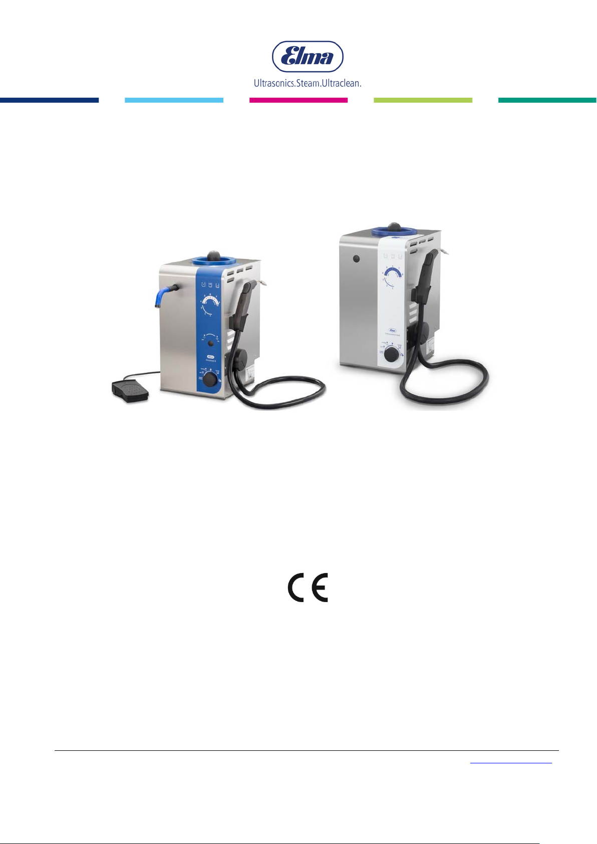
Elma ES8MED-HS, ES8-HS-FD, ES8-HS-FD-DL, ES8-HS-DL, ES8MED-HS-DL Operating Instructions Manual
...Page 1
Operating Instructions
Elmasteam 8 basic med
High-performance steam cleaner
English
Elma Schmidbauer GmbH Gottlieb-Daimler-Str. 17 D-78224 Singen Telephone +49 (0) 7731 / 882-0 Fax +49 (0) 7731 / 882-266 [email protected]
www.elma-ultrasonic.com
document ref. 1076604
Page 2

Contents
Contents
1 General points .................................................................. 4
2 Important Safety Instructions ............................................ 4
2.1 How to use this guide ................................................. 5
2.2 Description of the warning information on the device . 5
2.3 Important Information for Utilising the Device ............. 8
2.4 Information when Utilising as a Medical Device ........ 12
3 Product Description ........................................................ 14
3.1 Scope of Supply and Equipment .............................. 14
3.1.1 Elmasteam 8 basic med ............................... 14
3.1.2 Device Overview ................................................ 15
3.2 CE Conformity Declaration ....................................... 16
3.3 Operational Method .................................................. 16
3.4 TECHNICAL DATA .................................................. 17
3.5 Safety Equipment and Devices ................................ 18
3.6 Product Description .................................................. 19
3.6.1 Elements on the Device Front Side .................... 19
3.6.2 Elements on the Device Rear Side .................... 20
3.6.3 Operating Displays ............................................ 21
3.6.4 Saturated Steam wet/dry (optional) .................... 22
3.6.5 Programme Selection ........................................ 23
3.6.6 Handpiece (optional) .......................................... 24
3.6.7 Luer-Lock-Connection (med) ............................. 25
3.6.8 Fixed Nozzle (optional) ...................................... 26
4 Commissioning ............................................................... 27
4.1 Installation and Connection Conditions .................... 27
4.1.1 Assembling the Mains Supply Cable .................. 28
4.2 Assembling the Fixed Nozzle (Option) ..................... 29
4.2.1 Assembling the Foot Switch (option) .................. 31
4.3 Assembling the Compressed Air (option) ................. 33
4.4 Assembling the Fixed-Water Connection (Option device
with pump) ............................................................................ 34
4.5 Assembling the Water Connection to the Canister
(Option device with pump) .................................................... 36
4.6 Switching on the Device ........................................... 39
5 Description of the Operating Displays ............................. 40
6 Device filling/emptying .................................................... 45
6.1 Requirements for the Water Quality ......................... 47
6.1.1 Determining the Water Quality ........................... 47
6.2 Manual Filling ........................................................... 48
6.3 Automatic Filling with Pump (optional) ...................... 51
6.3.1 Filling with Fixed-water Connection (option) ........... 52
2
BA_Elmasteam_8_DE_Vers.07.206 © Elma Schmidbauer GmbH
Page 3
3
6.3.2 Initial Filling with th e Ca nister ............................ 54
6.4 Draining the Device .................................................. 55
7 Handling in Operation ..................................................... 57
7.1 Working with the Handpiece ..................................... 60
7.2 Working with the Fixed Nozzle ................................. 62
7.3 Operation with Saturated Steam wet/dry (option for
device with pump) ................................................................. 65
7.4 Programme Selection ............................................... 66
7.4.1 Selecting the Steam Outlet ................................ 67
7.4.2 Selecting Soft .................................................... 68
7.4.3 Selecting strong ................................................. 69
7.4.4 Selecting lock .................................................... 70
7.4.5 Service (Descaling) ............................................ 71
7.4.6 Settings ............................................................. 75
8 Safety / Maintenance / Repair Works ............................. 79
8.1 Regular Visual Controls............................................ 79
8.2 Flush the Pressure Vessel ....................................... 80
8.2.1 Cleaning the Sieve in the Water Connection ...... 83
8.3 Wear and Tear Parts ................................................ 84
8.3.1 O-ring in the Pressure Vessel Screw Cap .......... 84
8.3.2 O-ring Nozzle ..................................................... 84
8.3.3 Seal on the Collecting Tray ................................ 84
8.3.4 Hose (handpiece) .............................................. 84
8.4 Safety V alve ............................................................. 85
8.4.1 Inspect biannually .............................................. 85
8.4.2 Replacement every 3 years ............................... 86
8.5 Repair Works ........................................................... 87
8.6 Preparing the Device for Shipping ............................ 88
8.7 Troubleshooting ....................................................... 89
9 Decommissioning and Disposal ...................................... 92
10 Manufacturer´s Address / Contact Address .................... 92
© Elma Schmidbauer GmbH BA_Elmasteam_8_Vers.07.2016
Page 4
General points
4
Must be adhered to
before
commissioning
Disclaimer
1 General points
This operating manual is an integral part of the scope of delivery. It
must be retained close to the device and provided with resale of
device on the device.
We retain the right to implement amendments and/or alterations
through technical advancements compared to the illustrated
design in this operating manual without prior notice.
An operating manual cannot cover all conceivable applications.
Please contact your dealer or the manufacturer for more
information or for problems that are not covered in this operating
manual which are, or not, of a sufficient manner.
2 Important Safety Instructions
INFORMATION
Please read these instructions carefully before use
and only operate this electrical device in
accordance with the hereby entered instructions
and information.
Note additionally the instructions of this operating
manual with regard to the country-specific safety
regulations.
INFORMATION
No liability is assumed by the manufacturer for
damage to people, equipment, devices or cleaning
goods which are caused by improper use contrary
to the information in this operating manual.
The operator and/or owner is responsible for the
training of the operating personnel.
BA_Elmasteam_8_Vers.07.2016 © Elma Schmidbauer GmbH
Page 5
5
DANGER
WARNING
CAREFUL
INFORMATION
2.1 How t o use this guide
Please read these instructions carefully before use and only
operate this electrical device in accordance with the hereby
entered instructions and information.
Labels and symbols in these instructions
This symbol warns of a risk of injury caused by electricity.
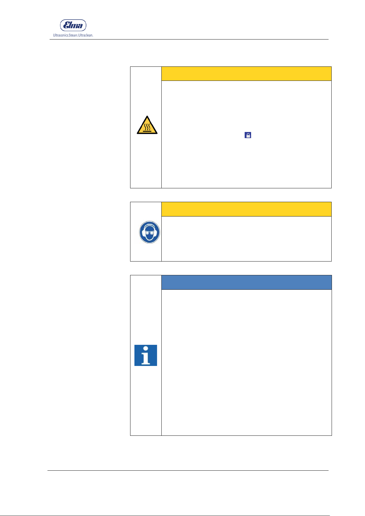
This symbol warns of a risk of personal injury from hot surfaces
and liquids.
This symbol warns of risk of injury from hot liquids and vapours.
This symbol warns against general risks of injury and/or property
damage.
This symbol warns of a risk of damage to property and indicates
additional information.
Important Safety Instructions
Signal words in these instructions
The signal word danger warns of serious injury or death.
The signal word warning warns of serious injury.
The signal word caution warns of minor to moderate injuries.
The signal word information warns of material damage and
indicates additional information.
2.2 Description of the warni ng information on the device
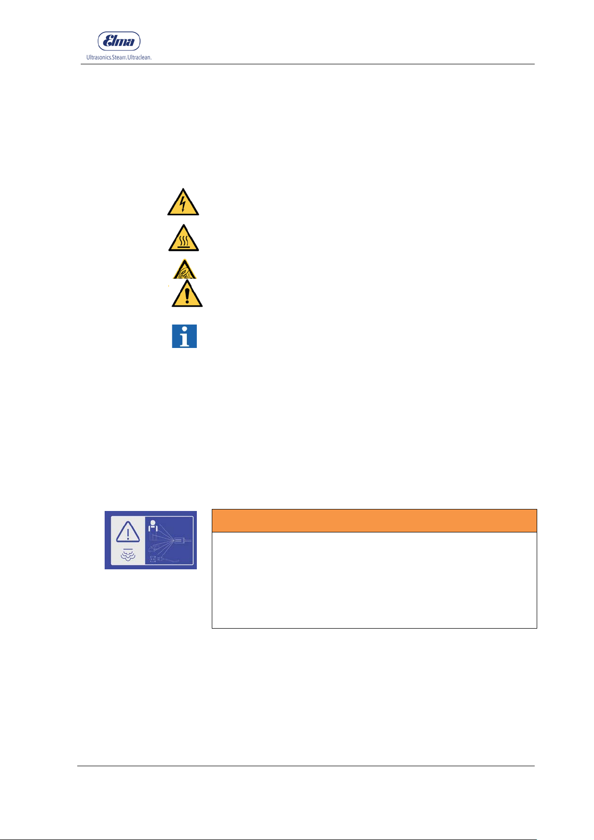
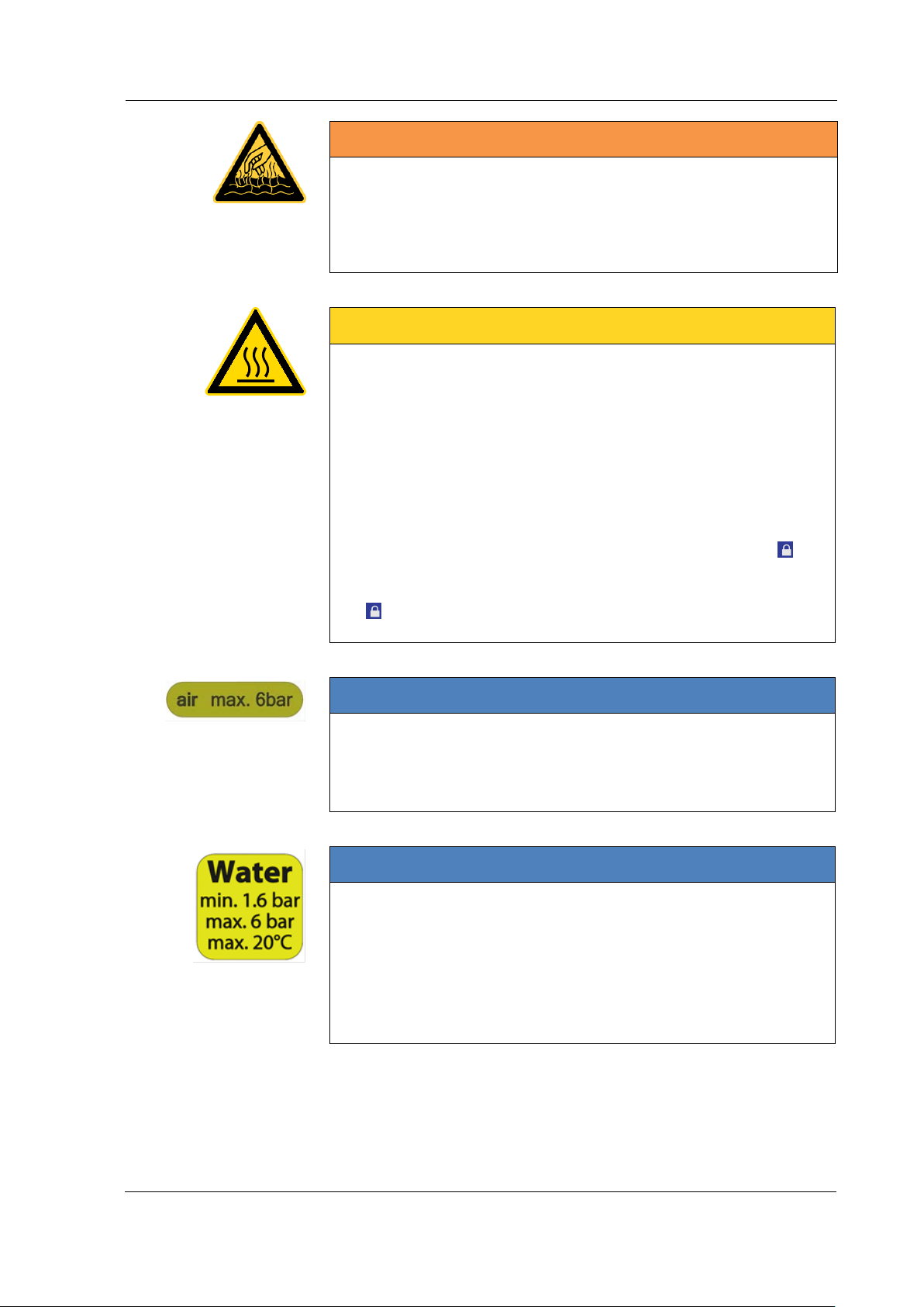
WARNING
High pressure jets!
Injuries caused by scalding!
• Never direct the jet at people, live electrical equipment or at
the device itself!
• Never direct the jet at yourself or others in order to clean
clothes or footwear.
© Elma Schmidbauer GmbH BA_Elmasteam_8_Vers.07.2016
Page 6
Important Safety Instructions
6
• Observe the gauge display!
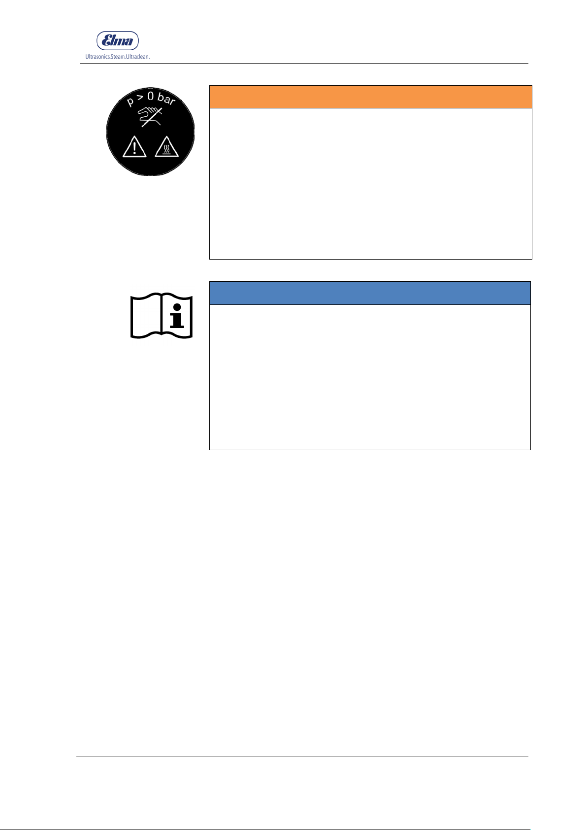
WARNING
Hot vapours/hot liquids
Injuries caused by scalding!
• Never open the drain cock when an excess pressure of > 0
CAREFUL
Hot surface areas/hot vapours
Injuries caused by burns or scalding!
• Never reach into the area of the upper vents as they can
• The ventilation slots in the area of the safety valve can
• Always wear suitable PPE
• Place the device in the lock position during application
• The device automatically switches off after expiry of the set
up has built up in the pressure vessel!
heat up during operation!
become hot after triggering by escaping steam!
(e.g. protective gloves, protective footwear, protective
clothing)
breaks.
time limit.
INFORMATION
Parts in the device can be damaged!
The connected pressurised air must not exceed a pressure of 6
bar.
(Applies only to devices with optional compressed air inlet)
INFORMATION
Parts in the device can be damaged!
The connected water pipe system must not exceed the
maximum water pressure of 6 bar is not exceeded and the
minimum water pressure of 1.6 bar not fall below.
The connected water pipe system must not exceed the
maximum temperature of 20°C.
(Applies only to units with optional water pump)
BA_Elmasteam_8_Vers.07.2016 © Elma Schmidbauer GmbH
Page 7
Important Safety Instructions
7
exception)
WARNING
Hot vapours/hot liquids
Risk of scalding from steam!
• Only open the pressure vessel screw cap when the device is
depressurised!
• Allow the pressure vessel to cool down before opening the
pressure vessel screw cap!
• Observe the gauge display (Chapter 3.6.3D)! The device
remains under pressure as long as one segment is
illuminated on the value scale on the gauge.
• Only fill with potable water or distilled (DI)! (Descaling as an
INFORMATION
Refer to the Operating Instructions
• Read the operating instructions completely before you
commence working with the device.
• Failure to observe these operating instructions can cause
serious injury or damage to the device.
• Always retain the operating instructions in the vicinity of
the device.
• The operating manual is part of the device. Always
transfer the operating instructions with the device when
you pass the device on to third parties.
© Elma Schmidbauer GmbH BA_Elmasteam_8_Vers.07.2016
Page 8

Important Safety Instructions
8
Intended Use
Warranty
Operating Personnel
Inspect for possible
transport damage
Installation
Mains Supply
Connection
Prevention of
Electrical Accidents
2.3 Important Information for Utilising the Device
Always implement the device according to the operating
instructions. No liability can be assumed by the manufacturer for
the safety of people, as well as the functionality of the device,
caused from improper use of the device.
This steam cleaner is intended exclusively for cleaning objects.
Living creatures must never be subjected to steam jets! Application
is only permitted in commercial areas!
When utilised as a medical product, please refer to the additional
information in Chapter 2.4.
3 years warranty when utilised for the intended use:
Actuations manual unit/foot switch: 37500 Units
Steam time: 500 h (saturated steam)
Standby time: 6000 h
Heating time: 900 h
For security and/or safety reasons, only qualified personnel who
are authorised and familiar with the operating instructions of this
steam cleaner may operate this steam cleaner. Unauthorised
personnel, especially children, must never operate this device.
Inspect the device after unpacking for possible transport damage.
Never commission the device when visible damage is identified.
Always contact the supplier and transport company in such cases.
Position the device on a stable, level, dry surface which is
insensitive to moisture. The ventilation slits must never be
covered. Ensure that the workplace is sufficiently ventilated!
The device must only be connected to a properly grounded
connection socket to comply with the safety regulations..
The technical specifications on the nameplate must correspond
with the available connecting conditions. In particular, the mains
supply voltage and current connected load.
To prevent electrical accidents, and damage to the device, the
device must never to subjected to steam jets or liquid penetration.
Always unplug the mains supply connection with damage to the
device or ingress of moisture.
The device may only be opened by authorised personnel. Unplug
the mains supply connection before opening the device.
Do not operate the device when a mains supply cable or other
important parts of the device are damaged e.g. safety elements or
steam nozzles.
The plug and coupling must be watertight when an extension cable
is utilised. Warning: Unsuitable extension cables can be
dangerous.
BA_Elmasteam_8_Vers.07.2016 © Elma Schmidbauer GmbH
Page 9
Important Safety Instructions
9
Filling
No chemical
additives
Descaling Resources
Maintenance and
Repair
Devices with Fixed
Water Connection
Devices with
Compressed Air
Connection
Cleaning Result
Upright Transport
Storage and
Transport Conditions
Disclaimer
Only fill the device with potable water or DI water.
Do not use any chemical additives. Only operate the device with
potable water or DI water. Descaling as an exception (Chapter
6.4.5).
Only utilise pure citric acid (45 g = 3 tablespoons of pure citric acid
dissolved in 1.5 litres of water) for descaling. Misuse can cause
damage e.g. on the pressure vessel seal.
Follow the instructions for maintenance works as described in
these operating instructions at regular intervals (Chapter 7.4 ) to
ensure the functionality and safety of the device.
Repair works must only be executed by authorised Elma
professionals and service centres. Disconnect the power supply
connection before commencing maintenance works or opening the
device.
Original parts must be utilised for repair works or any accessories.
Always close the water supply to the pump on the stopcock after
operation or when the device is left unattended.
Only utilise clean air. Do not use compressed air which includes
chemicals, synthetic oils containing organic solvents, salt or
corrosive gases etc. as this may cause damage or malfunctions on
the device.
Install an air filter close to the valve on the upstream side. Select a
filtration degree of maximum 5µm.
Remove excessive carbon dust by installing a micro-filter on the
upstream side of the valve. If excessive carbon dust is generated
by the compressor, then this may adhere in the valve and cause a
malfunction.
Maximum compressed air temperature: 40°C
Do not exceed the stated maximum air pressure as this may result
in personal injury and increased material wear and tear.
The user is responsible for the control of the cleaning result.
The device must be stored and transported upright when the
pressure vessel is full as otherwise residues can clog the steam
valve and steam pipes.
Care must be taken to prevent damage during storage and
transportation of the device. Basically, storage or transportation at
temperatures below the freezing point must be avoided. Freezing
water in the steam cleaning device can impair the function
sustainably. Drain the unit completely before storing or
transporting.
© Elma Schmidbauer GmbH BA_Elmasteam_8_Vers.07.2016
Temperature during storage: +5°C (+ 41°F) to + 40°C (+ 104°F)
Temperature during transport: -15°C (+ 43°F) to +60°C (+ 122°F)
Humidity and air pressure during storage and transport:
10% - 80% relative humidity; not condensing
Pressure range 500 hPa - 1060 hPa absolute
Elma Schmidbauer GmbH will reject all claims for damages or
warranty claims when:
Page 10
Important Safety Instructions
10
part thereof.
unit has cooled down.
High Temperatures
Nozzle
Pressure Vessel
Screw Cap
The product is utilised in any way for other than that intended
•
When unauthorised technical modifications, amendments and
•
The product was not repaired at a service centre authorised by
•
The product was utilised used despite obvious safety faults or
•
External forces
•
The prescribed maintenance works have not been conducted.
•
use as referred to in this manual.
alterations have been made to the product by third parties.
the manufacturer or was repaired without using original spare
parts.
damage being recognisable on the device.
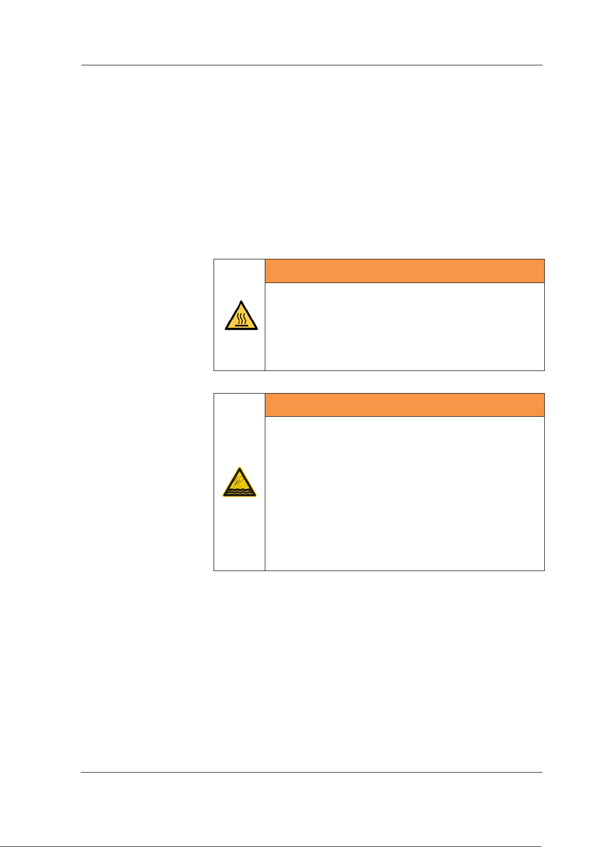
WARNING
High temperatures on the nozzle with nozzle tube!
Serious injuries from burns!
• Only touch the said areas with personal protective
equipment (e.g. protective gloves)
• Allow the unit to cool down before touching any
WARNING
Hot vapours/hot liquids
Risk of scalding from open pressure vessel screw cap
• Hot water splashes and evaporates from the filling
opening
• Turn off the device immediately using the mains
supply switch, unplug the mains supply cable from
the power supply or set the programme selection
to steam outlet (Chapter 6.4.1)
• Let the appliance cool down
• Only close the pressure tank screw cap once the
BA_Elmasteam_8_Vers.07.2016 © Elma Schmidbauer GmbH
Page 11
Important Safety Instructions
11
people, fixtures or equipment.
equipment during the stay in the workspace.
The outflow of steam at high velocity causes
Hot steam when
triggering the safety
pressure valve
Noise Emission
Electrostatic
discharge
CAREFUL
Hot steam! Steam will escape from the ventilation
openings for a short time with a possible
triggering of the safety valve.
Risk of scalding!
• Unplug the mains supply plug.
• Place the device in the lock position during
application breaks.
• Keep unauthorised persons away from the device.
• Securely fix the manual unit in the programme
steam outlet.
• Ensure that the escaping steam will not endanger
CAREFUL
Noise Emission!
Steam cleaning devices can cause annoying sounds
during operation.
• Always wear personal ear and hearing protection
INFORMATION
electrostatic charge generated by friction to
accumulate on the nozzle as well as on the product to
be cleaned. The electrostatic charge developed on the
handpiece is continuously dissipated via the ground
connection of the device. Depending on external
conditions such as insufficient conductivity of the floor
and/or shoes, dissipation of electrostatic charge of the
product to be cleaned may be impaired.
This absolutely harmless but unpleasant state can be
sensed as “tingling” or “electric shock” (a similar effect
may occur, for example, in carpets or velvet car
seats). The discharge that takes place here can be
observed as a visible spark discharge from the product
to be cleaned to the handpiece.
© Elma Schmidbauer GmbH BA_Elmasteam_8_Vers.07.2016
• It is recommended in such cases to ground the
product to be cleaned or, if necessary, the wrist of
the user (e.g. with an ESD wrist strap).
Page 12
Important Safety Instructions
12
Intended Use
Intended Use
Disinfect the
Instruments before
Cleaning
Safety Precautions
for the User
2.4 Information when Utili s ing as a Medical Device
The products of the Elmasteam 8 med Series are intended for
cleaning hard to reach areas on medical instruments. This
cleaning is NOT a replacement for the subsequent cleaning,
disinfection or sterilisation in automated standard processes (e.g.
RDG or autoclave).
The device is particularly suitable for the cleaning of:
• Joint areas of joint instruments
• Fluted surfaces of e.g. forceps
• Cleaning of melted fabric material on electro-surgical
instruments (e.g. bipolar forceps)
• Cleaning of drills and cutters (drilling/milling heads with e.g.
residual tissue, bone meal)
• Pre-cleaning of the lumen of hollow instruments.
The utilisation of Elmasteam has to be previously clarified with the
instrument manufacturer for temperature-sensitive instruments.
(Steam temperature Chapter 3.4 Technical Data)
The plastic-coated portion of the instrument must not be processed
with the device (risk of detachment) when pre-cleaning of
instruments made of composite material (e.g. steel-plastic in
bipolar forceps).
Steam cleaner for manual pre-cleaning or treatment of
instruments.
Only medical devices that are approved and reusable for
reprocessing must be cleaned (refer to the information from the
medical device manufacturer in accordance with EN ISO 17664).
The operation must only be performed by trained personnel and
not by children. Operating and equipment must be executed in
accordance with the conditions and the media defined in the
operating instructions. The service intervals as well as regional
regulations for inspecting the device must be adhered to.
Instruments must be disinfected in accordance with the
instructions from the instrument manufacturer prior to processing
and treating with the device e.g. as in disinfectant solution
according to the VAH list.
INFORMATION
Safety Precautions for the User!
The exact adherence to all safety regulations must be observed,
in particular the wearing of suitable protective clothing (jacket,
cap, heat resistant gloves, a mask and face shield (visor)).
BA_Elmasteam_8_Vers.07.2016 © Elma Schmidbauer GmbH
Page 13
Important Safety Instructions
13
Wear a suitable mouth protection
Generation of
Aerosols
WARNING
Generation of Aerosols!
Transmission of pathogens!
• For protection of the personnel in the area of
instrument cleaning, a suitable suction device and
drip device are strongly recommended.
(e.g. Elma steam workplace with autonomous
suction and Hepa Filter)
•
© Elma Schmidbauer GmbH BA_Elmasteam_8_Vers.07.2016
Page 14

Product Description
14
3 Product Description
3.1 Scope of Supply and Equipment
3.1.1 Elmasteam 8 basic med
• 1 Basic Device with 5 litres of tank volume
• 1 Maintenance Hose
• 1 Mains Supply Cable
• 1 Filling Sieve
• 1 Flushing Set
• 3 O-rings for pressure vessel screw cap
• 1 Water Hose (fixed-water supply)
• 1 Luer-Lock-connection set (med)
• 1 Fixed Nozzle (optional)
• 1 Set of Operating Instructions
• 1 Information Data Sheet for Water Quality
• 1 Information Data Sheet for the Warranty Conditions
Accessories:
• 1 canister with hose, ventilation and level monitoring
• 8-piece adapter set for Luer-Lock-connection (med)
• Fixed nozzle (with 2 mm nozzle diameter)
• Manual Unit with hose 2.3m
• Evaporating Bowl
BA_Elmasteam_8_Vers.07.2016 © Elma Schmidbauer GmbH
Page 15
15
HS Manual Unit FD Fixed Nozzle DL Compressed
Air
MED
Luer Lock
ND Saturated
Steam
ES8-HS
O
ES8-HS-FD
O
O
ES8-HS-DL
O O
ES8-FD
O
ES8-P-HS
O
O
ES8-P-HS-FD-DL
O O O O
ES8-P-HS-DL-ND
O O O
O
ES8-P-FD
O O
3.1.2 Device Overview
Product Description
Design with
P Pump
ES8MED-HS O
ES8-HS-FD-DL O O O
ES8MED-HS-DL O
ES8-FD-DL O O
ES8-P-HS-FD O O
ES8-P-HS-DL O
ES8MED-P-HS-DL O
O O
O O
O O O
O
O
ES8-P-FD-DL O O O
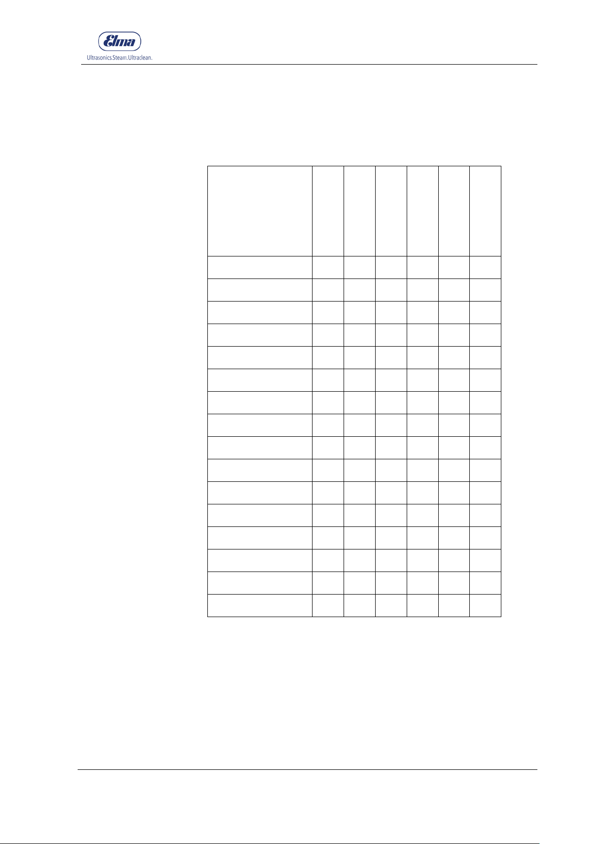
Table 3.1.2 Device Overview
© Elma Schmidbauer GmbH BA_Elmasteam_8_Vers.07.2016
Page 16

Product Description
16
Generating Pressure
Steam Outlet
Saturated Steam
Operating Resources
3.2 CE Conformity Declaration
This steam cleaning device fulfils the CE marking criteria and EU
directives:
• 2014/35/EU Low-voltage Directive
• 2014/30 / EU EMC Directive
• 93/42 / EEC Medical Device Directive
• 2011/65 / EC RoHS Directive
The declaration of conformity can be requested from the
manufacturer.
3.3 Operational Method
Water is heated by a heater to 185°C in a manually or
automatically filled pres sure vessel, A steam pressure of maximum
8 bar is thereby generated.
The steam is provided through the nozzle(s) for availability.
Steam and hot water are thereby mixed from the pressure vessel.
(Optional)
The mixing ratio can be adjusted via the rotary knob for wet/dry.
Operate the device exclusively with potable water or DI water. The
conductivity of the water must be at least 2μS / cm.
BA_Elmasteam_8_Vers.07.2016 © Elma Schmidbauer GmbH
Page 17
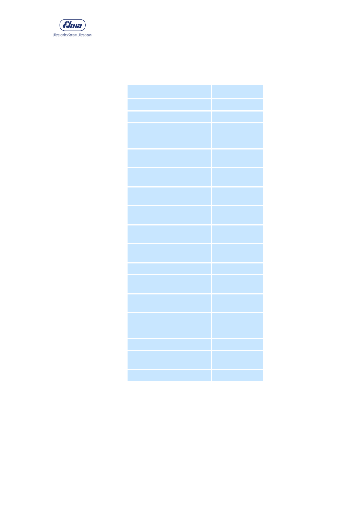
17
Sound pressure level at 8 bar
3.4 TECHNICAL DATA
Product Description
Mains voltage (Vac) 220 - 240
Mains frequency (Hz) 50 / 60
Mains Supply Connection Shockproof
Mains impedance maximum
(Ohm)
Power consumption
maximum (W)
dBA)
Pressure in the pressure
vessel (bar)
Pressure vessel volumes
(litres)
Maximum filling volume
(litres)
Elmasteam 8
safety plug 1
phase
0.155
3120
93
8
5
3.8
* Heating up time (minutes) 20
Steam temperature outlet Approximately
160 °C
Steam temperature in the
boiler
Dimensions without manual
unit bracket and fixed nozzle
W x D x H (mm)
Material housing Stainless steel
Pressure vessel Stainless steel /
Weight (kg) Approximately 20
* Approximate value for maximum-filled pressure vessel
Approximately
185 °C
285 x 350 x 520
aluminium bronze
© Elma Schmidbauer GmbH BA_Elmasteam_8_Vers.07.2016
Page 18

Product Description
18
3.5 Safety Equipment and Devices
The devices are equipped with all prescribed safety devices and/or
equipment such as e.g.:
• Safety pressure relief valve
• Safety pressure vessel closure for inadmissible opening of the
pressure vessel screw on the filler pipe.
• Low voltage in handpiece
BA_Elmasteam_8_Vers.07.2016 © Elma Schmidbauer GmbH
Page 19
Product Description
19
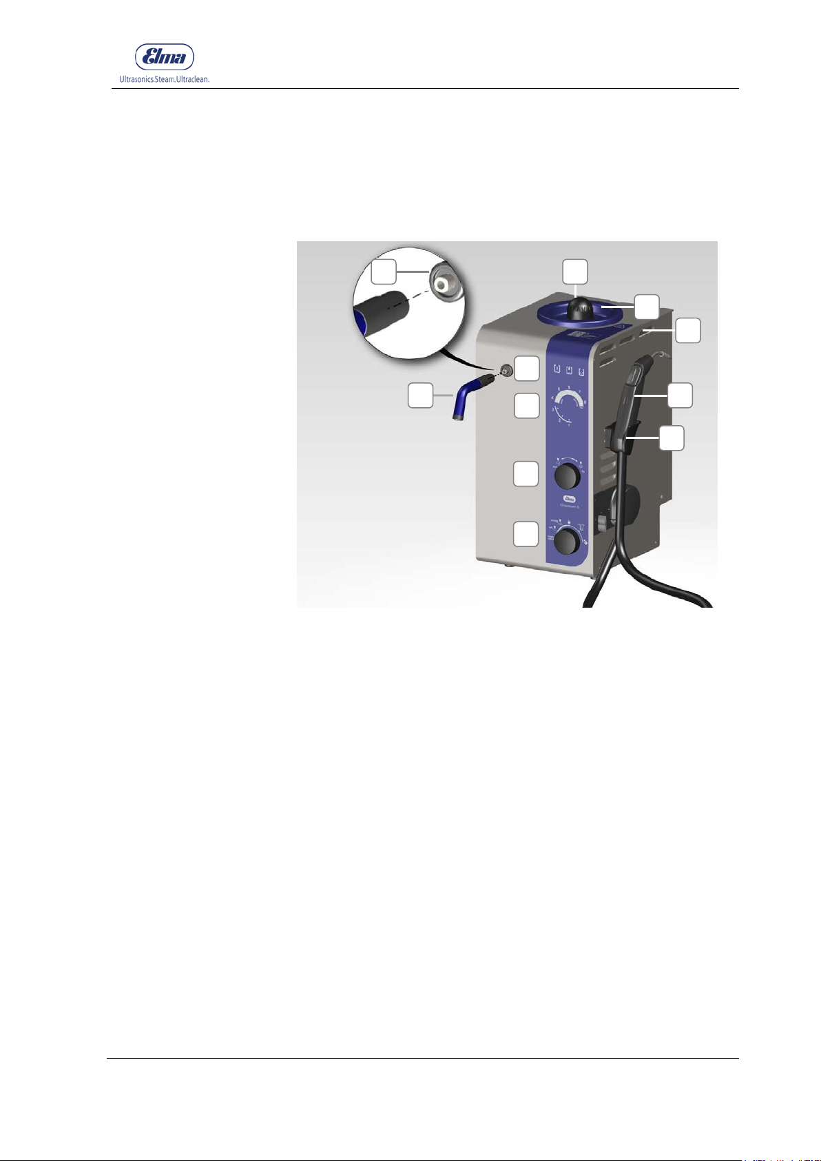
A B C
D
E
F
G
H
I
J
K
A
G
C
D
E F K B I J H
3.6 Product Description
3.6.1 Elements on the Device Front Si de
Figure 3.6.1: View of the device, front side
Connection For attaching the fixed nozzle (optional)
Fixed Nozzle (optional)
Operating Displays Warning/Filling Level/Service
Gauge Indicator 1-8 bar /Service Mode (Level indicator 1-8)
Rotary knob wet/dry (Setting the mixing ratio).
Refer to Chapter 6.3 for a description
Rotary knob for programme selection: Turn the ro tary knob to
select the function and press the rotary knob to confirm the
selection. Refer to Chapter 6.4 for a description
Bracket For handpiece (optional)
Handpiece (optional)
Ventilation Openings (lateral on the housing)
Drip Tr ay (Manual filling) for overflowing water
Pressure Vessel Screw Cap: Filling opening for manual filling.
Screw to open in an anti-clockwise direction.
© Elma Schmidbauer GmbH BA_Elmasteam_8_Vers.07.2016
Page 20
Product Description
20
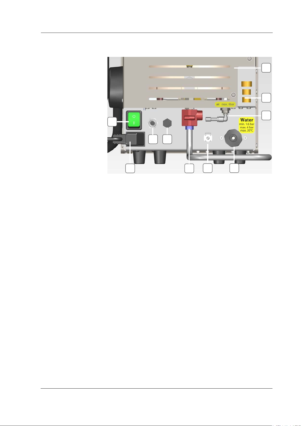
A B C D E F G
H I J
A E C J H
G I B
D
3.6.2 Elements on the Device Rear Side
F
Figure 3.6.2: Device, rear side
Ventilation Openings
Safety Valve
Input Connection for External Compressed Air Supply
(optional)
Connection for Water Supply to the Pump (optional)
Connection for Exhaust Hose for the Canister (optional)
Ball V alve with Prote ctive Co ver for emptying the pressure
vessel and for maintenance works.
Connection for Filling Level Sensor on the Canister (optional)
Connection for Foot Switch for the assembled Fixed Nozzle
(optional)
Connection for Mains Supply Cable
On/Off Switch (Mains switch, illuminates as green in operation)
BA_Elmasteam_8_Vers.07.2016 © Elma Schmidbauer GmbH
Page 21
21
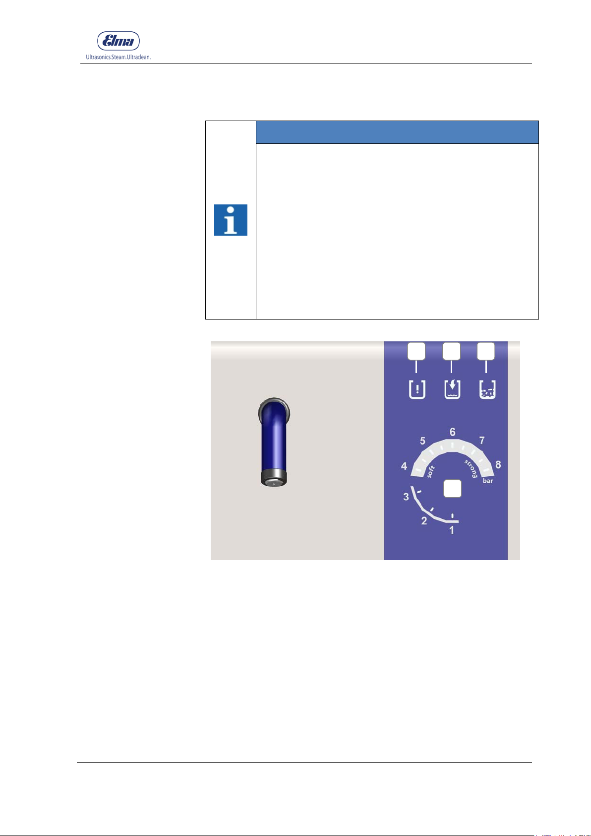
Warning (A)
Filling Level (B)
Service/Descaling (C)
Gauge (D)
Signal Tone
D
3.6.3 Operating Displays
INFORMATION
Always observe the operating displays during operation!
• Warning (A) signals warnings
(illuminates/flashes red)
• Filling-level (B) signals the filling-level status
(illuminates/flashes blue)
• Service/Descaling (C) signals a descaling for the
device (illuminates/flashes orange)
• Gauge (D) signals the current pressure value
(illuminates green), adjusted operating pressure
(flashes green) until the pressure is achieved.
• Step Display (D) for programme-controlled
descaling pr ogramme.
Product Description
A B C
Figure 3.6.3: Operating Displays
Illuminates or flashes red for warnings for Fillin g Level/Descaling
Illuminates or flashes blue to indicate the filling level status in the
pressure vessel or the optional canister
© Elma Schmidbauer GmbH BA_Elmasteam_8_Vers.07.2016
Illuminates or flashes orange to signal descaling for the device
Illuminates or flashes green to indicate the operating pressure,
pressure value as well as the step display for the descaling
programme
Sounds for warnings, signals the urgency
Page 22
Product Description
22
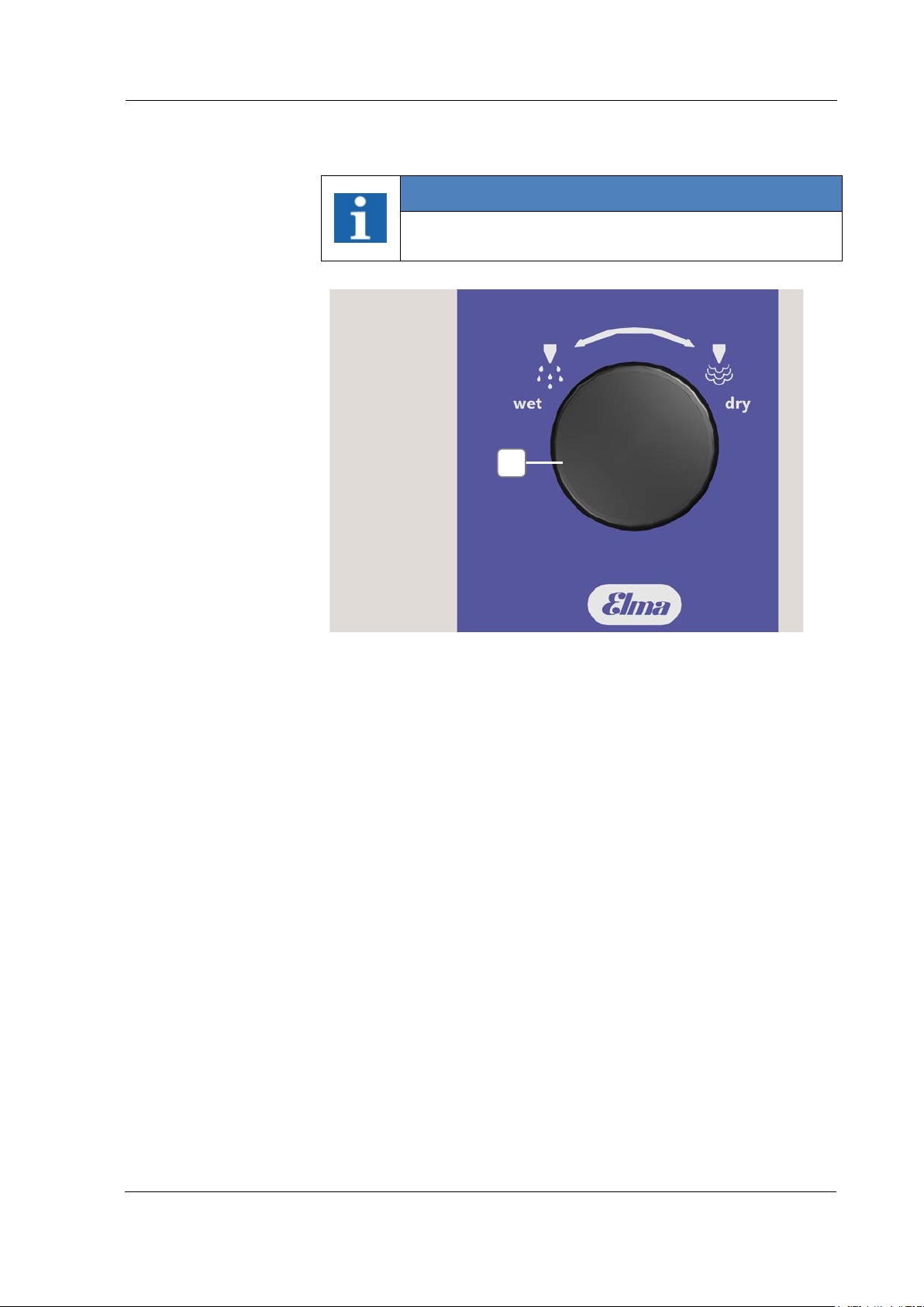
Wet
Dry
A
3.6.4 Saturated Steam wet/dry (optional)
INFORMATION
Saturated steam is available on the handpiece (Chapter
6.1 Working with the handpiece).
Figure 3.6.4: Rotary knob wet/dry
Turn the rotary knob (A) to the end-limit "wet" = 100% operating
with saturated steam
Turn the rotary knob (A) to the end-limit "dry" = 100% operating
with dry steam
The intensity of the mixing ratio of the steam function will be
regulated by turning the rotary knob (A) as 0-100%. The mixing
ratio can also be adjusted during the steam operation.
BA_Elmasteam_8_Vers.07.2016 © Elma Schmidbauer GmbH
Page 23
23
A B C
A B C D E
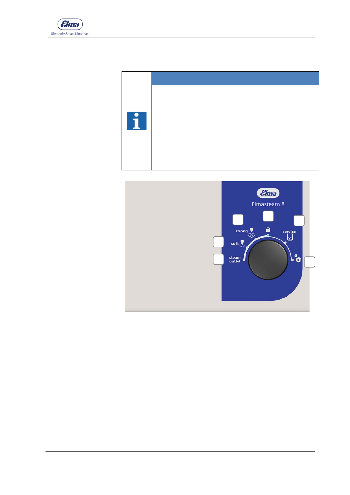
3.6.5 Programme Selection
INFORMATION
Rotary knob for programme selection.
Simple utilisation: Turn the rotary knob to select the
function and press the rotary knob to confirm the
selection.
The selected programme lights up as blue on the
display segment (point).
The device is pre-set to the factory settings (Table
Chapter 6.4.6.1 Settings).
The device automatically changes after the expiry of the
set time to lock (Figure 3.6.5-D).
Product Description
F
Figure 3.6.5: Rotary knob, programme selection
steam outlet to drain the residual pressure in the pressure vessel
(before opening the pressure vessel screw cap). Steam can be
discharged through the handpiece or fixed nozzle (Chapter 6.4.1)
soft for the press ure range 4-6 bar. The adjusted operating
pressure on the gauge illuminates as green until the pressure has
been built up/reduced. The pressure achieved illuminates as green
on the gauge.
strong for the pressure range 6-8 bar. The adjusted operating
pressure on the gauge illuminates as green until the pressure has
been built up/reduced. The pressure achieved illuminates as green
on the gauge.
© Elma Schmidbauer GmbH BA_Elmasteam_8_Vers.07.2016
Page 24
Product Description
24
D
E F A
B
A+B
C
D
A B C
D
Lock for application breaks. To prevent inadvertently escaping
steam or compressed air. Foot switch for the fixed nozzle and the
handpiece are deactivated.
service (descaling) for program-c ontrolled descaling. Follow the
step indicator on the gauge (Chapter 6.4.5 Service (Descaling)).
Settings for steam soft, steam strong, time to lock, time to eco,
measurement value, lime content, reset the device to factory
settings (Chapter 6.4.6 Settings).
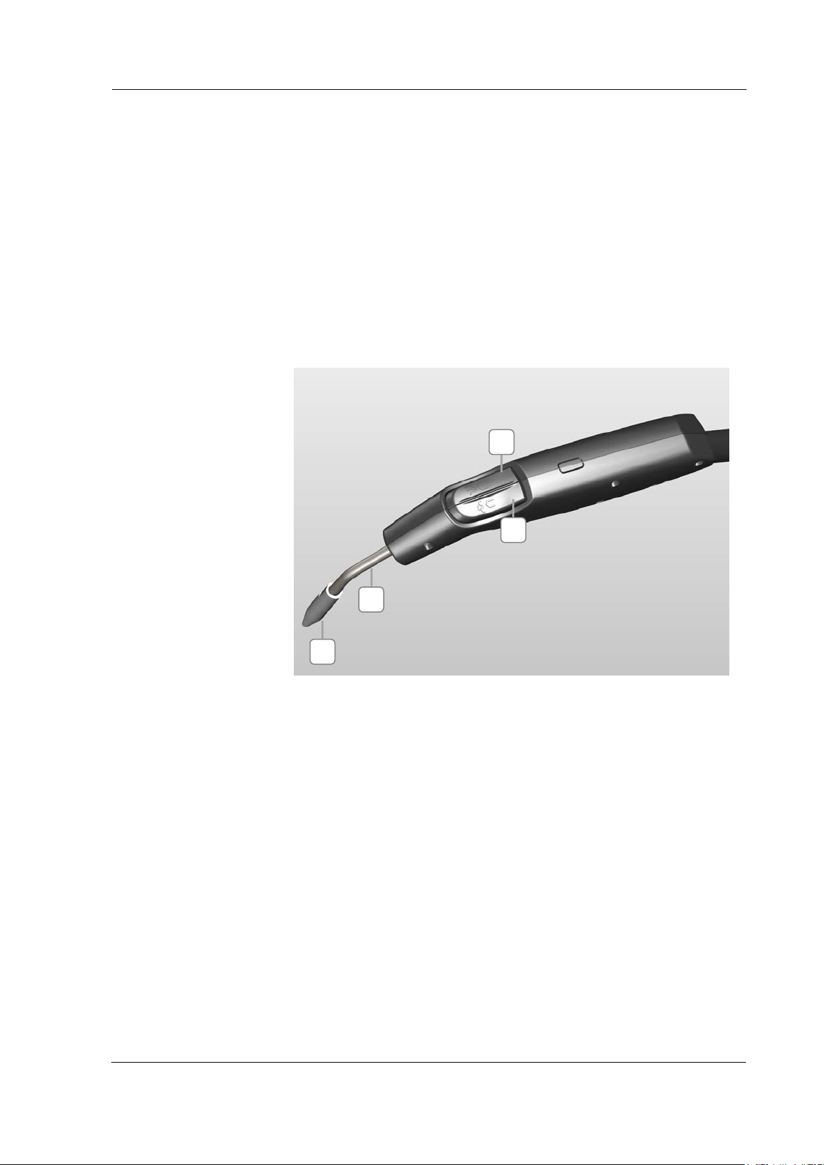
3.6.6 Handpiece (optional)
Figure 3.6.6: Handpiece
Activated Compressed Air (optional)
Activated Steam
Activated Steam (both button pressed)
Nozzle Pipe
Nozzle Pipe or optional Luer-Lock connection (MED)
BA_Elmasteam_8_Vers.07.2016 © Elma Schmidbauer GmbH
Page 25
25
A
A
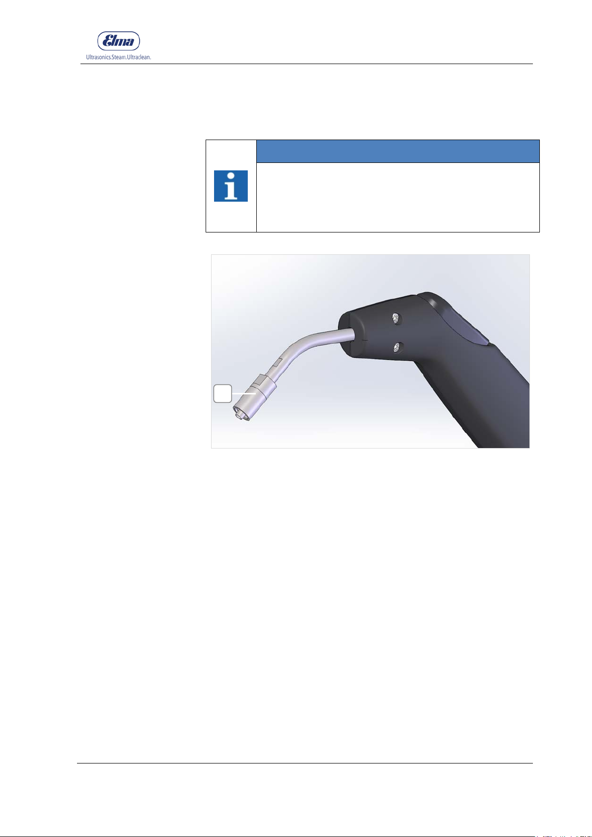
3.6.7 Luer-Lock-Connection ( med)
INFORMATION
The Luer-Lock connection on the device is intended for
connecting special adapters that are designed for
cleaning the inside of hollow instruments. The medical
adapter is included in the scope of delivery for medical
devices.
Product Description
Figure 3.6.7: Handpiece with Luer-Lock-Connection (med)
Luer-Lock Connection (med)
© Elma Schmidbauer GmbH BA_Elmasteam_8_Vers.07.2016
Page 26
Product Description
26
A
A
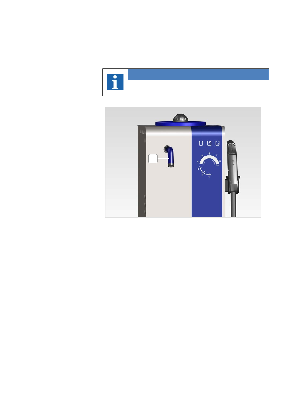
3.6.8 Fixed Nozzle (optional)
INFORMATION
The steam operation with the fixed nozzle will be
activated via the foot switch.
Figure 3.6.8: Fixed Nozzle
Fixed Nozzle
BA_Elmasteam_8_Vers.07.2016 © Elma Schmidbauer GmbH
Page 27
Commissioning
27
Packaging
Inspect for transport
damage
Installation
Environmental
Conditions
Nameplate
A
4 Commissioning
4.1 Installation and Connecti on Conditions
Retain the original packaging when possible or dispose of it
professionally in accordance with applicable waste disposal
regulations.
You can also return the surplus packaging (at your expense) to the
manufacturer.
Inspect the device after unpacking for possible transport damage
before initial commissioning. The device must not be connected to
the mains supply when damage has been identified. Always
immediately contact your supplier and transport company in such
cases.
Position the device on a stable, level, dry surface which is
insensitive to moisture. The ventilation slits must never be
covered. Retain a distance of at least 10 cm to the walls on the
rear side. Ensure adequate ventilation in the workplace.
The device may only be operated:
• in well-ventilated internal areas
• at an ambient temperature of 5 - 40 º C [41 - 104 °
F] *)
• at a maximum relative humidity of 80% at 31 ° C [87.8 ° F],
decreasing linearly to 50%
relative humidity at 40 ° C [104 ° F] *)
• With a mains power supply when the voltage fluctuations
do not exceed 10% of the nominal value
*) Between 5 - 30 ° C [41-86 ° F], the device is ready for operation at a
relative humidity of up to 80%. At temperatures from 31 - 40 º C [87.8 to
104 ° F], the humidity must decrease proportionally in order to ensure
operational readiness (e.g., at 35 ° C [95 ° F] = 65% humidity at 40 ° C
[104 ° F] = 50% humidity). The device must not be operated at
temperatures above 40 ° C [104 ° F].
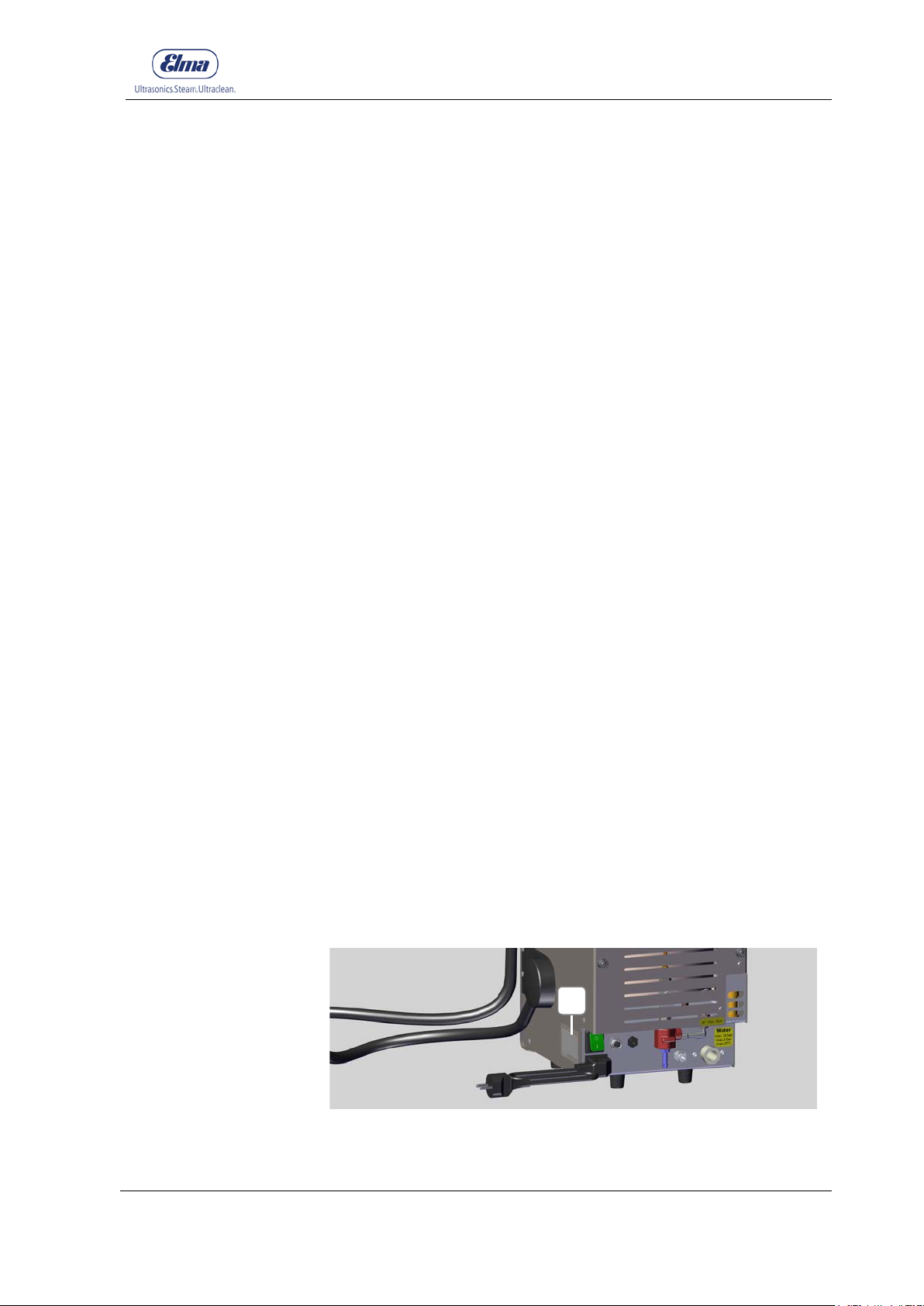
Connect the device to a suitable mains supply plug socket. The
technical data on the nameplate (Figure 4.1-A) must correspond
fully with the available connecting conditions, in particular mains
voltage and current connected load.
© Elma Schmidbauer GmbH BA_Elmasteam_8_Vers.07.2016
Figure 4.1: Nameplate (on the side of the unit)
Page 28
Commissioning
28
towards the device.
be used!
Connecting the
Device to the Mains
Supply
Assembling the
DANGER
Risk of electric shock!
Serious injuries / death!
• Connect the device to a suitable mains supply plug
socket
• The technical data on the nameplate (in particular
mains voltage and current connected load) must
correspond with the available connecting
conditions.
• Place the appliance on a dry, flat and stable
surface.
• Ensure adequate ventilation.
• Keep the installation area and housing dry.
• Steam and/or hot water outlets must never point
4.1.1 Assembling the Mains Supply Cable
Mains Supply
Cable
INFORMATION
Assembling the Mains Supply Plug
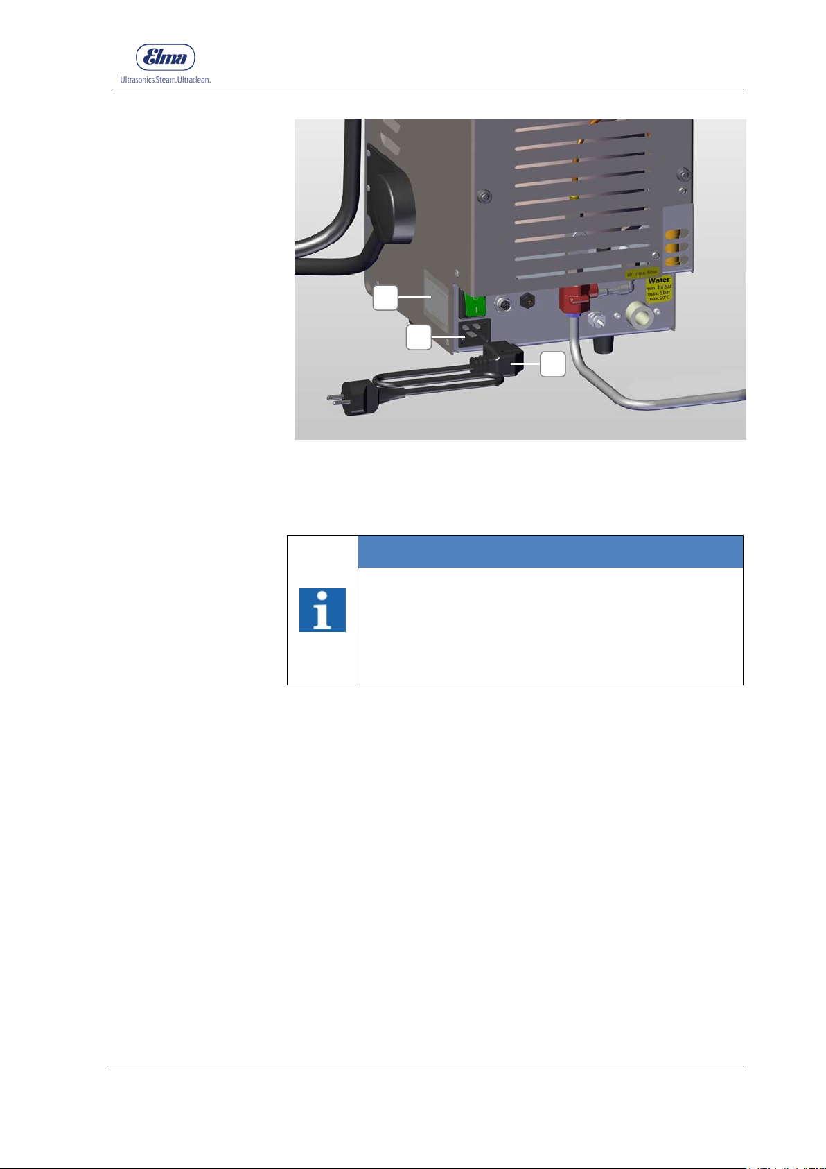
• Observe the technical data on the nameplate
(Figure 4.1.1-C)! Make sure that the electrical plug
socket has the same voltage as that indicated on
the nameplate.
• The plug socket for the mains supply cable must
be easily accessible. In an emergency, pull the
mains plug out of the plug socket!
• Inspect the mains supply cable for damage before
using it. A damaged mains supply cable must not
1. Connect the mains supply cable (Figure 4.1.1-A) to the
connector (Figure 4.1.1-B).
2. Plug the other end of the mains supply cable into the
prescribed plug socket.
BA_Elmasteam_8_Vers.07.2016 © Elma Schmidbauer GmbH
Page 29
29
depressurised.
Assembling the
B A C
Figure 4.1.1: Mains Supply Cable
Commissioning
4.2 Assembling the Fixed Nozzle (Option)
INFORMATION
Only assemble the fixed nozzle with switched off
and depressurised devices!
• To prevent that people could be scalded by built-up
Fixed Nozzle
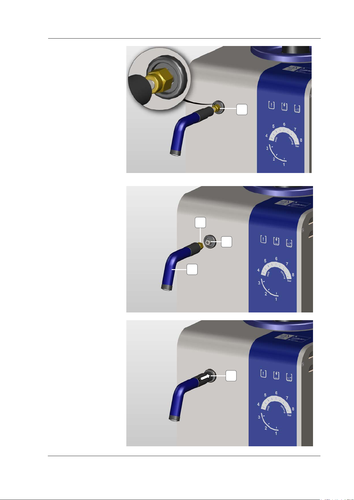
1. Remove the dummy plugs by unscrewing the nut (A) with an
open-ended spanner SW 12 mm (Figure 4.2.1).
2. Screw the fixed nozzle (B) with the nut (C) by hand (hand tight)
until it stops on the connecting piece (D) on the device (Figure
4.2.2).
3. Tighten the nut of the fixed nozzle with a quarter turn with an
open-ended spanner SW 12 mm.
4. Inspect whether the nut is tightened and the fixed nozzle is
fixed to the steam outlet downwards.
pressure causing accidentally escaping steam!
• Ensure that the device is switched off and
5. Slide the black protective cover in the arrow direction over the
nut (Figure 4.2.3.).
© Elma Schmidbauer GmbH BA_Elmasteam_8_Vers.07.2016
Page 30
Commissioning
30
A D E
Figure 4.2.1: Union nut with dummy plugs
C
B
Figure 4.2.2: Screwing on the Fixed Nozzle
Figure 4.2.3: Pushing on the black protective cover onto the nut
BA_Elmasteam_8_Vers.07.2016 © Elma Schmidbauer GmbH
Page 31
31
Assembling the
A C B
4.2.1 Assembling the Foot Switch (option)
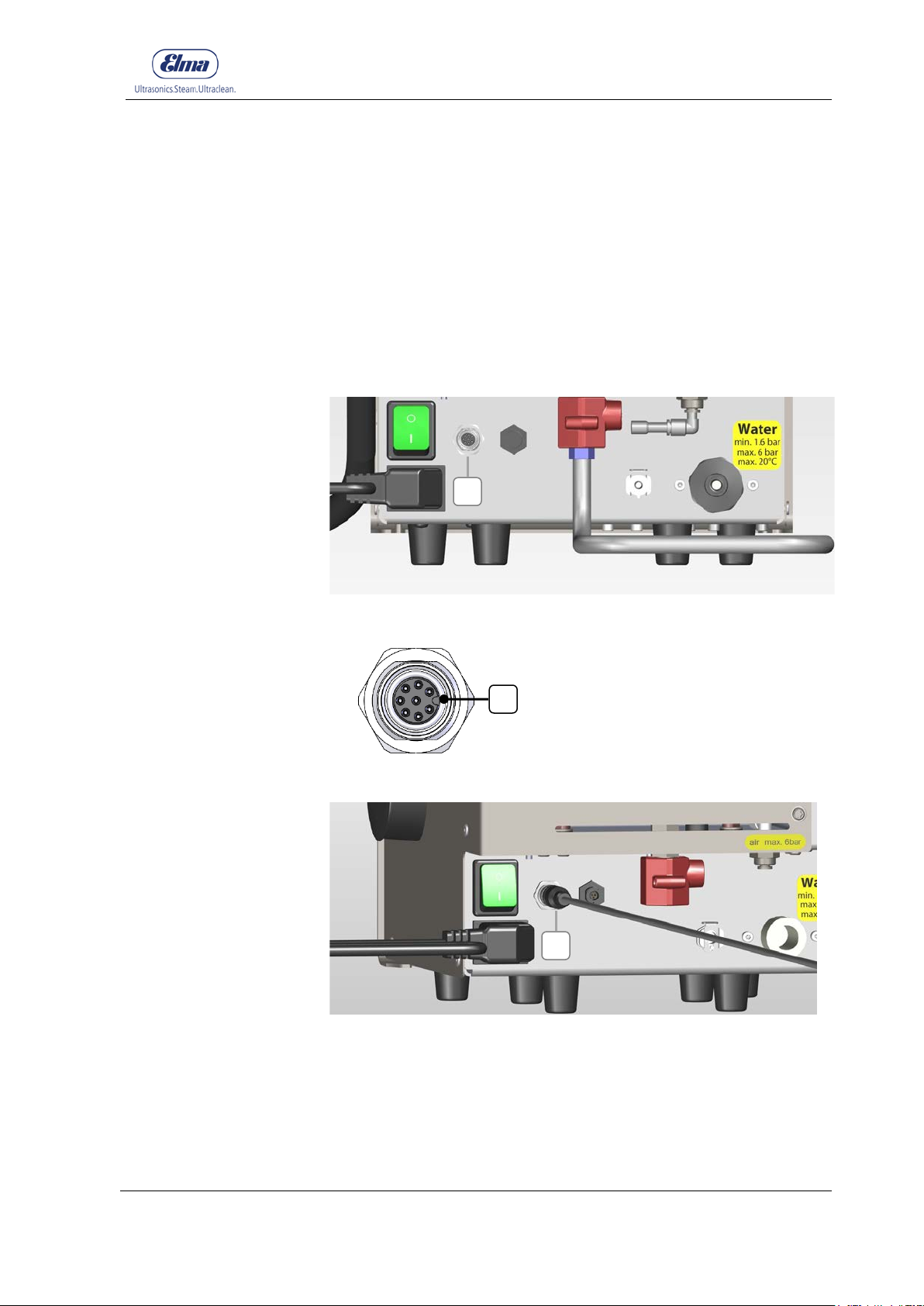
1. The plug for the foot switch will be screwed onto the
Foot Switch
connection (Figure 4.2.1.1-A).
Observe the plug direction when plugging in (Figure 4.2.1.2-B)!
The plug clicks during rotation!
Manually tighten the plug until it stops turning (Figure 4.2.1.3-
C)
Commissioning
Figure 4.2.1.1: Connection for the Foot Switch (Rear panel)
Figure 4.2.1.2: Aligning the plug (B)
Figure 4.2.1.3: Plug for the Foot Switch (Rear side of the device)
© Elma Schmidbauer GmbH BA_Elmasteam_8_Vers.07.2016
Page 32
Commissioning
32
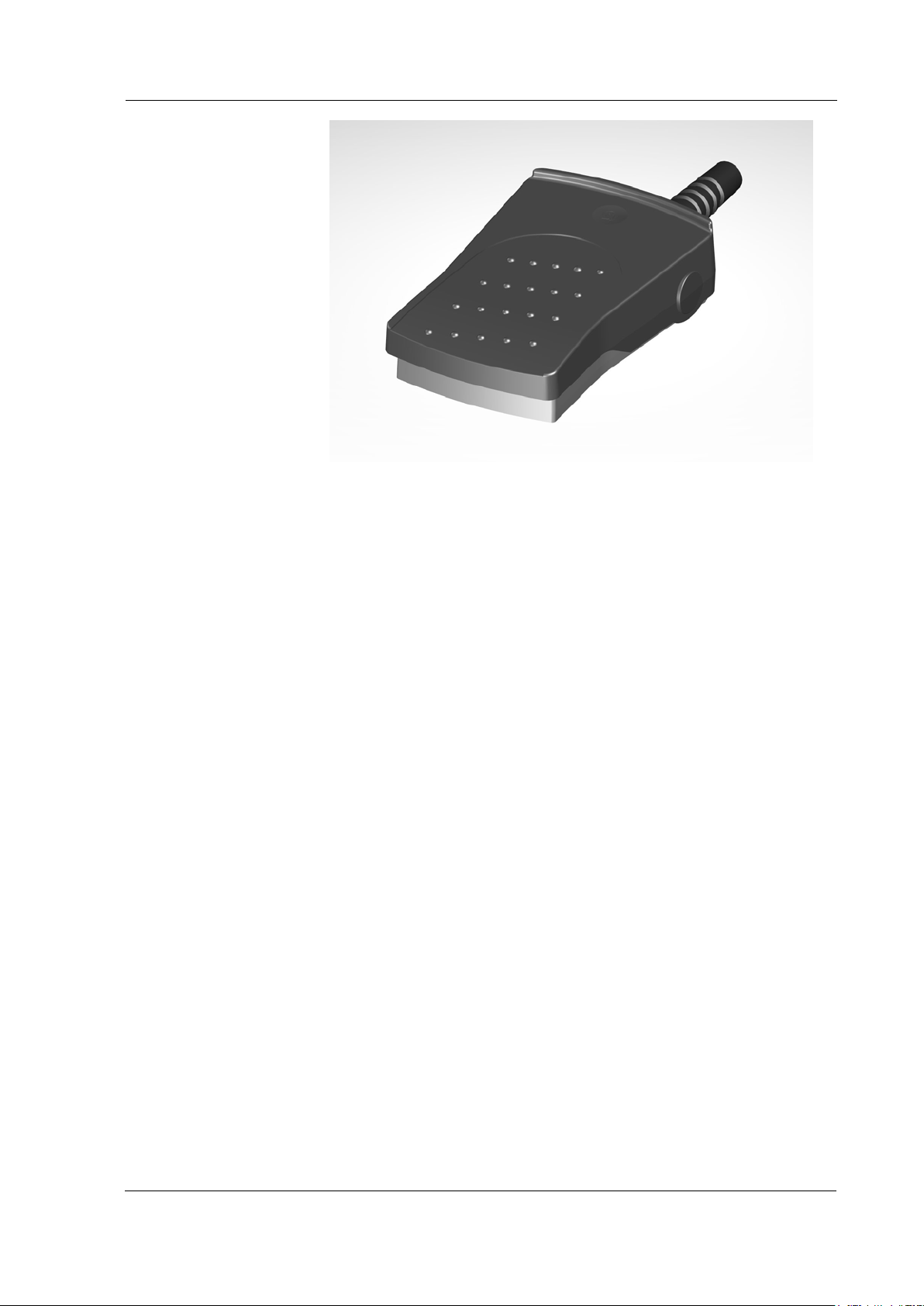
Figure 4.2.1.4: Foot Switch
BA_Elmasteam_8_Vers.07.2016 © Elma Schmidbauer GmbH
Page 33
Commissioning
33
• Ensure that the device is switched off.
Assembling the
A B C C D
4.3 Assembling the Compresse d Air (option)
INFORMATION
Only assemble the compressed air when the
device is switched off!
• Connect the device to a compressed air supply
Compressed Air
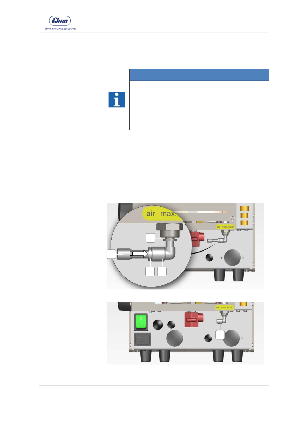
1. Remove the blind plug (4.3.1-A). For this purpose, press the
locking ring (4.3.1-B) in the arrow direction while pulling the
plug (4.3.1-A) in the reverse direction.
2. Push the compressed air hose (Ø6 mm) in direction of the
arrow until it stops in the angled connection screw (4.3.2-C).
with a maximum pressure of 6 bar!
• The compressed air must be free from dirt particles
(Chapter 2.3)
3. Option: Insert the angled connection screw (4.3.1-C) to
connect the compressed air hose directly into the connection.
(4.3.1-D).
Figure 4.3.1: Blind plug for compressed air connection (A)
© Elma Schmidbauer GmbH BA_Elmasteam_8_Vers.07.2016
Figure 4.3.2: Connection for compressed air (without blind plug)
Page 34
Commissioning
34
depressurised.
Assembling the
D A B
4.4 Assembling the Fixed-Wate r Connec t ion (Option device with pump)
INFORMATION
Only assemble the fixed-water connection with
switched off and depressurised devices!
• The minimum water pressure of 1.6 bar must be
retained. The maximum water pressure of 6 bar
must not be exceeded. Components within the
device may be damaged.
• Utilise the supplied water hose. If necessary, an
extension hose (2 m) can be ordered as an
accessory.
• Ensure that the device is switched off and
fixed-water
connection
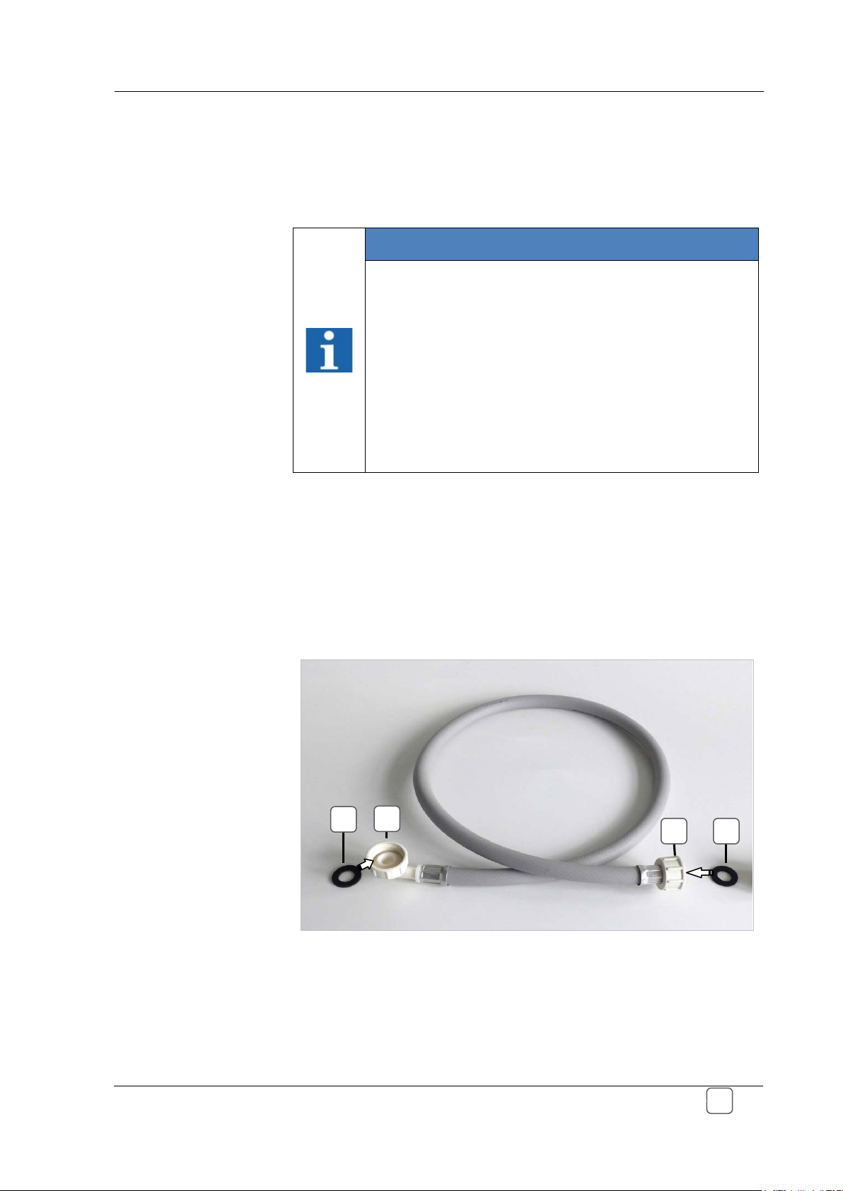
1. Attach the flat seals (A) from the scope of delivery in the
screwed threads (B + C). (Figure 4.4. 1)
2. Screw on the screwed thread (Figure 4.4. 1-B) of the water
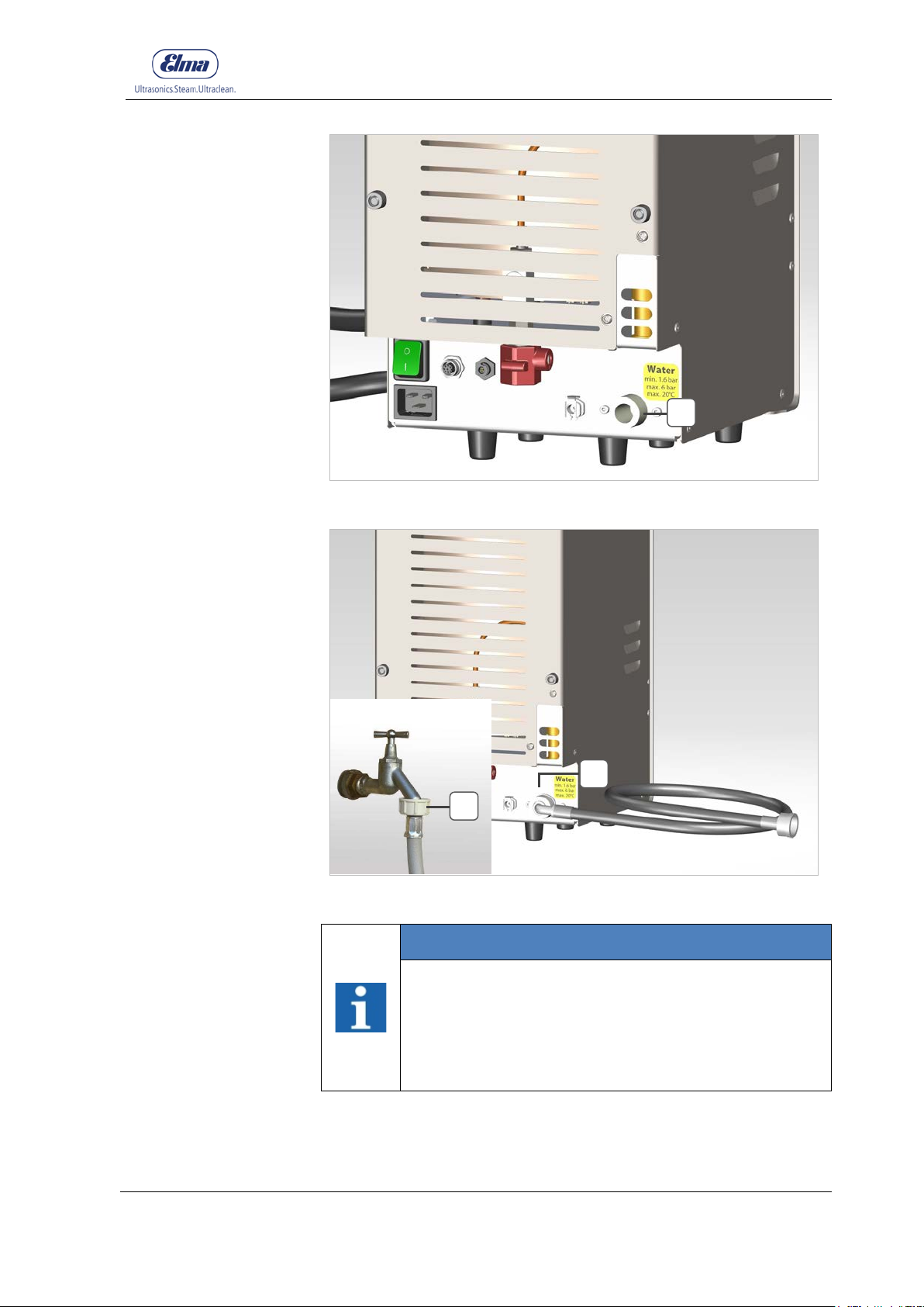
hose onto the water connection of the device. (Figure 4.4.1.2D)
3. Screw on the screwed thread (Figure 4.4. 1-C) of the water
hose onto the connection for the water pipe. (Figure 4.4. 3-E)
C A
Figure 4.4.1: Water hose with flat seals (scope of delivery)
BA_Elmasteam_8_Vers.07.2016 © Elma Schmidbauer GmbH
Page 35
Commissioning
35
tightness.
After the
E
F
D
Figure 4.4.2: Device connection (D) for water supply (water pipe)
© Elma Schmidbauer GmbH BA_Elmasteam_8_Vers.07.2016
assembly
Figure 4.4.3: Connected water hose
INFORMATION
Inspect the secure fixing for the fixed-water
connection!
• Maintain a proper and secure fixing for the water
hose.
• Inspect the connections (Figure 4.4.3-E + F) for
Page 36
Commissioning
36
these to the device!
Assembling the
D E B A C
4.5 Assembling the Water Connection to the Canister (Option device with pump)
INFORMATION
Only assemble the water connection with switched
off and depressurised devices!
• Utilise the supplied accessories. (Hose, ventilation
hose, cable for filling level monitoring, canister)
• Ensure that the device is switched off and
Water Supply
Canister
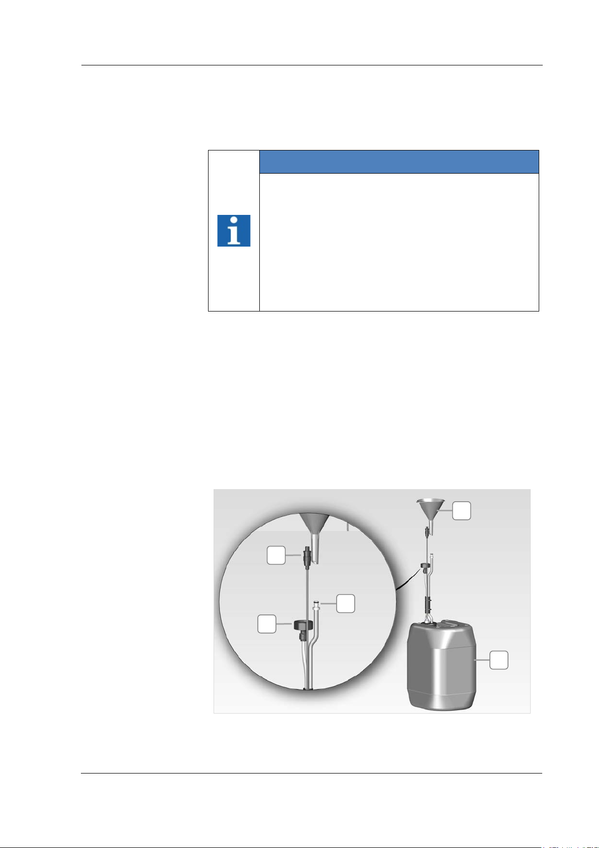
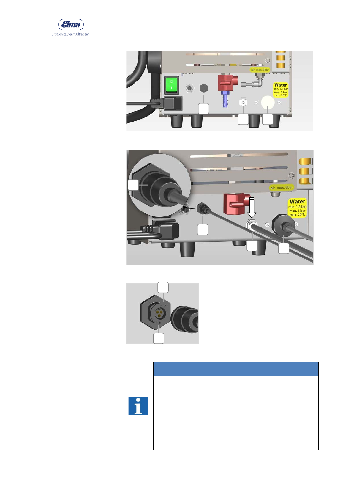
1. Screw on the screwed thread (Figure 4.4.1-A) of the water
hose onto the water connection of the device (Figure 4.5.2-F).
Inspect whether the seal is positioned correctly in the screwed
thread (Figure 4.5.1-A).
depressurised.
• The connections (hose, ventilation hose and cable
for filling level monitoring) for the canister are
prepared and connected to the canister. Connect
2. Connect the cable connector (Figure 4.5.1-B) for the fill level
monitoring to the connection (Figure 4.5.2-H) and turn the front
cap (Figure 4.5.3-I) until it locks. Observe the plug direction
(Fig 4.5.4-J).
3. Insert the ventilation hose (Figure 4.5.1-C) into the connector
(Figure 4.5.2-G).
Figure 4.5.1: Canister with acc ess or ies
BA_Elmasteam_8_Vers.07.2016 © Elma Schmidbauer GmbH
Page 37
Commissioning
37
the direction of the arrow!
After the
F H G H G F I J J
Figure 4.5.2: Connections for the canister (rear side of the device)
assembly
Figure 4.5.3: Connections for the canister connected
Figure 4.5.4: Plug alignment (J)
INFORMATION
Inspect the secure fixing of the water connection
for the canister!
• Maintain a proper and secure attachment of the
connections.
• Inspect the connections (Figure 4.4.3-E + F) for
leak tightness and function.
• Ensure when connecting the ventilation hose that
the locking lever (Fig 4.5.3-G) points downwards in
© Elma Schmidbauer GmbH BA_Elmasteam_8_Vers.07.2016
Page 38
Commissioning
38
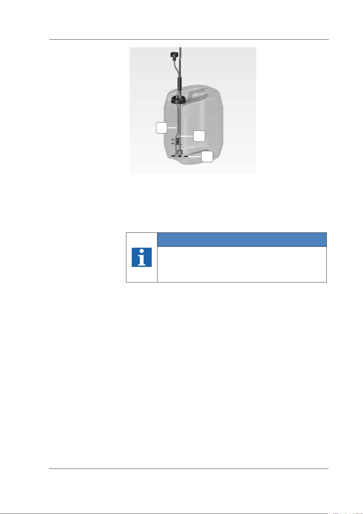
are set to the same level (M) (Figure 4.5.5)
Level for the water
connection and
filling level cable
K L M
Figure 4.5.5: Water hose and cable
The hoses and cables in the canister are pre-assembled. It may be
that these have been displaced during transport or unpacking.
Inspect hose (K) and cable (L). Align these when necessary to the
same level (M) when they have been displaced.
INFORMATION
Pump Operation
• The trouble-free functioning of the pump operation
is guaranteed when water hose (K) and cable (L)
BA_Elmasteam_8_Vers.07.2016 © Elma Schmidbauer GmbH
Page 39
39
programme.
Prerequisite
Switching on the
A
4.6 Switching on the Device
INFORMATION
Utilise the last programme selection
The device will start up with the last programme
selection when it is switched on. When the machine
has heated up, then you can implement the last
programme which was utilised or switch to another
Commissioning
Device
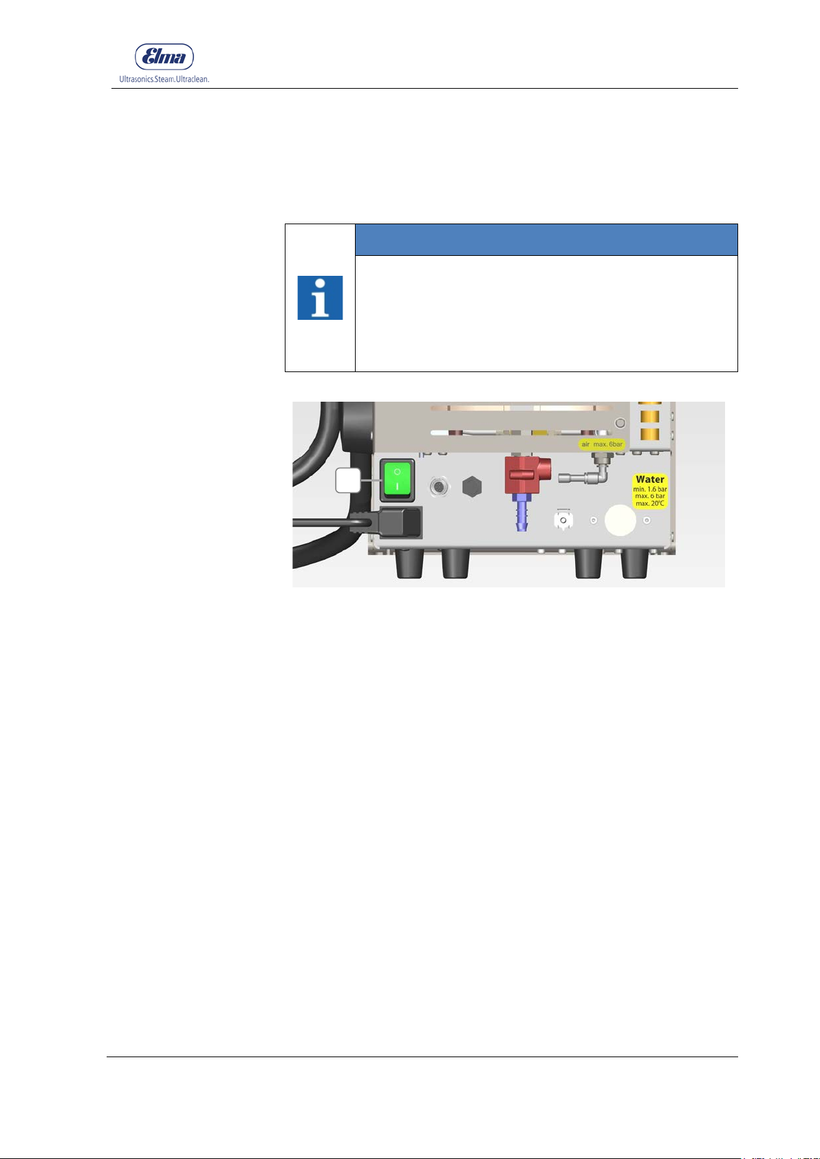
Figure 4.6.1: Device, rear side
The mains supply cable is plugged into the appropriate socket.
The commissioning was executed.
1. Switch on (I) the mains supply switch (A). The mains switch
illuminates as green when the device is switched on. The
device will immediately start to heat up when there is sufficient
filling level in the pressure vessel (Chapter 5).
© Elma Schmidbauer GmbH BA_Elmasteam_8_Vers.07.2016
Page 40
Description of the Operating Displays
40
Operating soft / strong
Pre-set
The device heats up or
Scales of values
The currently achieved
Warning (A)
Filling Level (B)
Service/Descaling (C)
Gauge (D)
Signal Tone
A D B C D
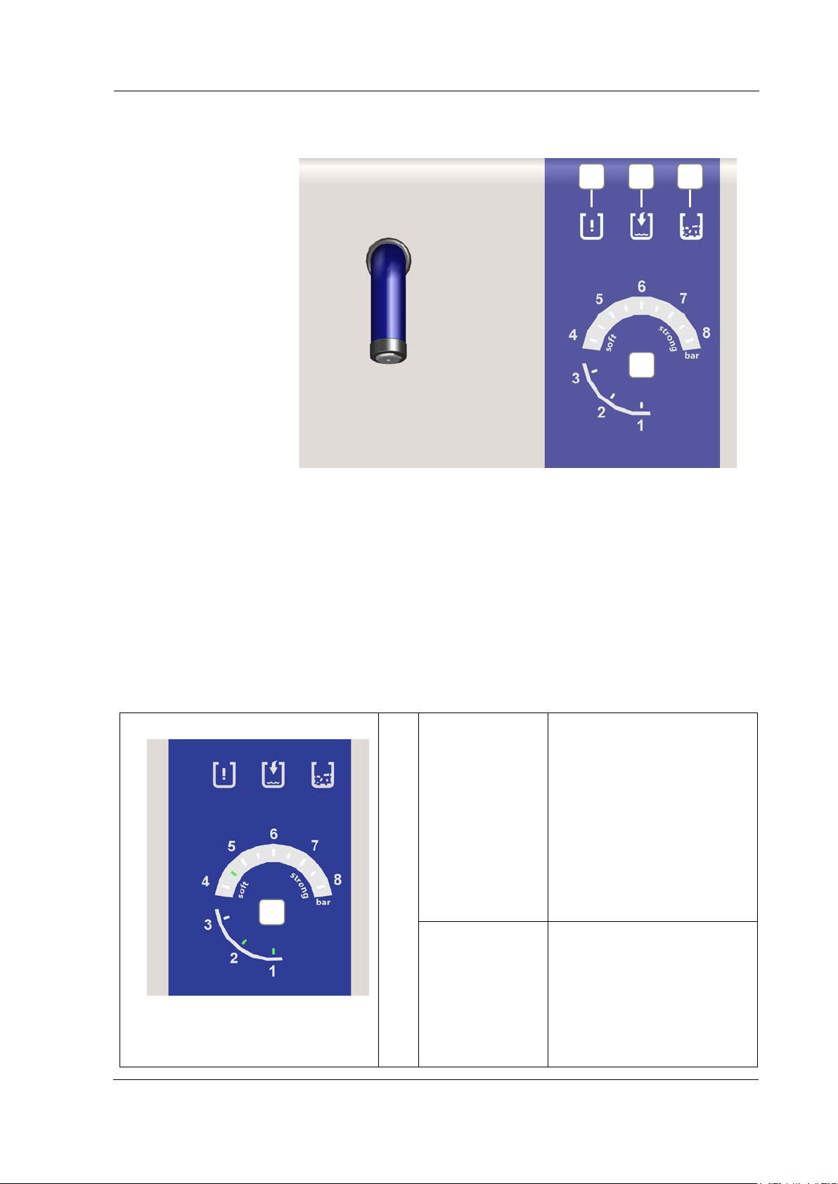
5 Description of the Operating Displays
Figure 5.1: Operating Displays
Illuminates or flashes red for warnings for Filling Level/Descaling
Illuminates or flashes blue to signal the filling level status in the
pressure vessel or the optional canister
Illuminates or flashes orange to signal descaling for the device
Illuminates or flashes green to indicate the operating pressure,
pressure value as well as the step display for the descaling
programme
Sounds for warnings, signals the urgency
operating
pressure for the
function soft or
strong flashes
green on the
scale of values
of the gauge (D)
cools to the pre-set
operating pressure
The current achieved
pressure illuminates on the
scale of values
The device is ready for use
when the scale of values
illuminates up to operating
pressure
on gauge (D)
illuminates as
green
pressure values illuminate
on the scale of values as
1-8
Example:
At 2 bar pressure, the scale
of values illuminates as 1-2
BA_Elmasteam_8_Vers.07.2016 © Elma Schmidbauer GmbH
Page 41
Description of the Operating Displays
41
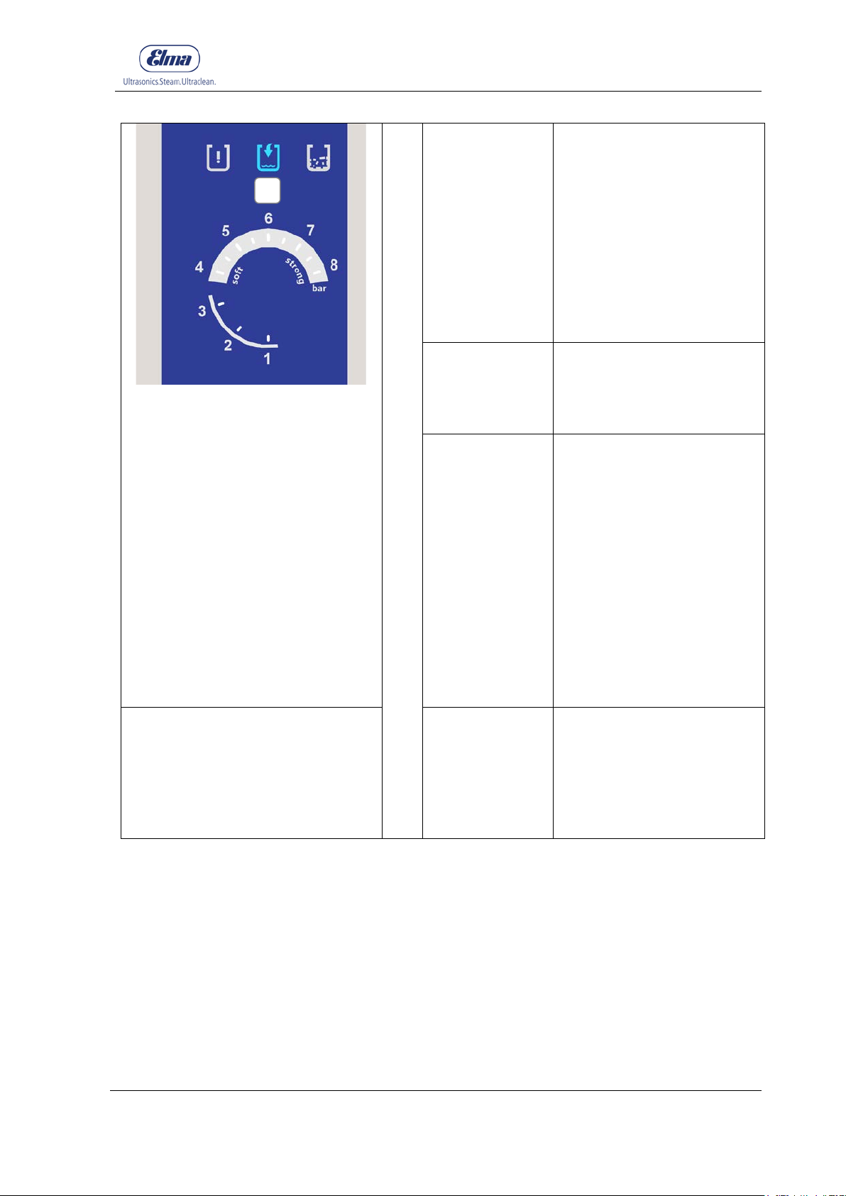
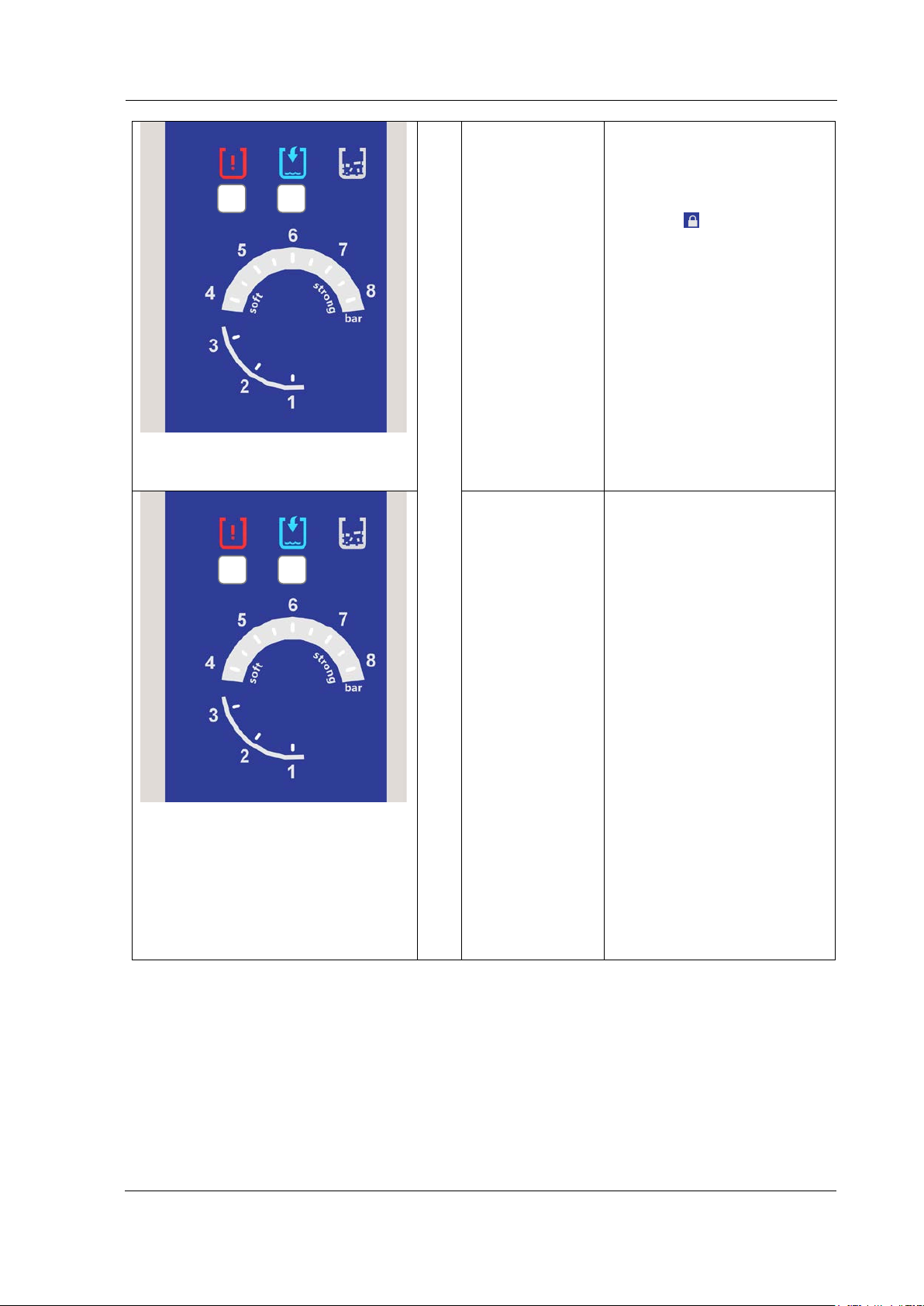
Filling Levels
Filling Level (B)
The device is not
Filling Level (B)
The device is completely
Filling Level (B)
The filling level in the
Filling Level (B)
Reserve indicator, device
B
illuminates as
blue
The device is
switched on at
the mains switch
and is
depressurised!
light goes out
(When filling)
completely filled
The filling level of the
device is between minimum
and maximum
The device can be filled
The display goes out as
soon as the pressure is built
up in the device (only for a
device without pump)
filled
Do not continue to fill the
device
flashes blue
(Device with
pump)
canister is low (min.)
Fill the canister
Canister is not connected to
the device
Inspect the connection
cable to the canister
flashes blue
(Device without
pump)
No or too low water
pressure (minimum 1.6 bar)
Open the water supply
and/or inspect water
pressure
and/or pressure vessel is
nearly empty.
© Elma Schmidbauer GmbH BA_Elmasteam_8_Vers.07.2016
Page 42
Description of the Operating Displays
42
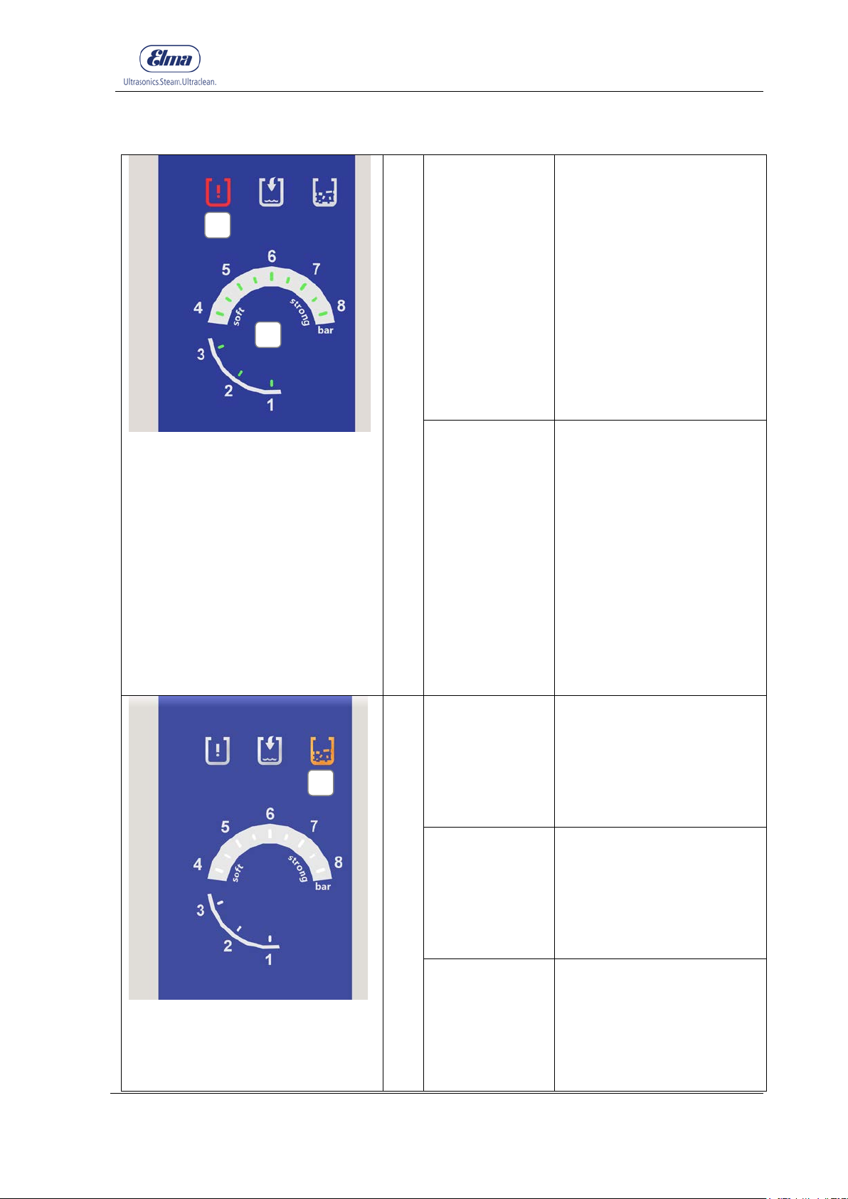
Filling Level (B)
Filling level low, below the
Filling Level (B)
With automatic filling, the
A
B
illuminates as
blue
B A
Warning (A)
flashes red
Warning Tone
sounds
continuously in
operation
soft/strong
minimum
Switch off the warning tone,
select the function steam
outlet or
lock in the
programme selection
Device with/without pump:
Fill the device manually
- Fill the device to filling
level minimum, the
display warning (A) goes
out
- Fill the device to filling
level maximum, the
display warning (B) goes
out
flashes blue
Warning (A)
flashes red
(Device with
pump)
filling process will not be
started (safety shut-down of
the pump)
Fill the device manually to
filling level minimum (2
litres)
Inspect the ventilation hose
on the canister and, where
necessary, connect it.
Device with fixed-water
supply:
Inspect the hose connection
Switch off the device: Let it
cool down
Switch on the device:
automatic filling
(depressurised devices start
with the filling proces s
again)
BA_Elmasteam_8_Vers.07.2016 © Elma Schmidbauer GmbH
Page 43
Description of the Operating Displays
43
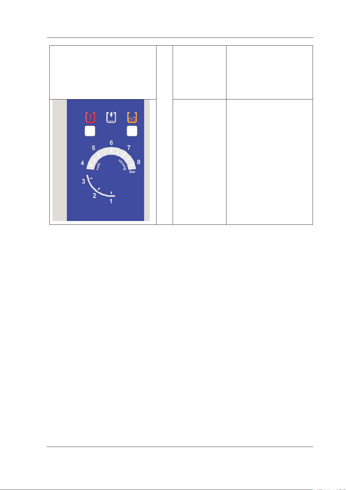
Warnings
Warning (A)
An excess pressure has
Warning (A)
The device has built up no
Service (Descale)
Service
1. Command for the device
Service
2. Command for the device
Service
3. Command for the device
A D C
flashes red
Gauge (D)
flashes green
(all scales of
values flashing)
been created in the device
Automatic shut-down of the
heating
Switch the device On/Off
Device with compressed air:
Inspect the compressed air
pipes for pressure
(maximum 6 bar)
Inspect whether the device
is in the function Service
(Descale)
flashes red
pressure (within a limited
time)
Pressure vessel screw cap
is missing or not completely
closed
Warning: Unplug the mains
supply/switch off the
device/set the function for
steam outlet
The heater is defect: Send
the device to the service
centre
(Descale) (C)
to descale
illuminates as
orange
(Descale) (C)
to descale
flas hes orange
(Descale) (C)
flas hes orange
Warning Tone
sounds
to descale
Warning Tone will
sound for 20 seconds
after switching on, if the
device has not been
© Elma Schmidbauer GmbH BA_Elmasteam_8_Vers.07.2016
Page 44
Description of the Operating Displays
44
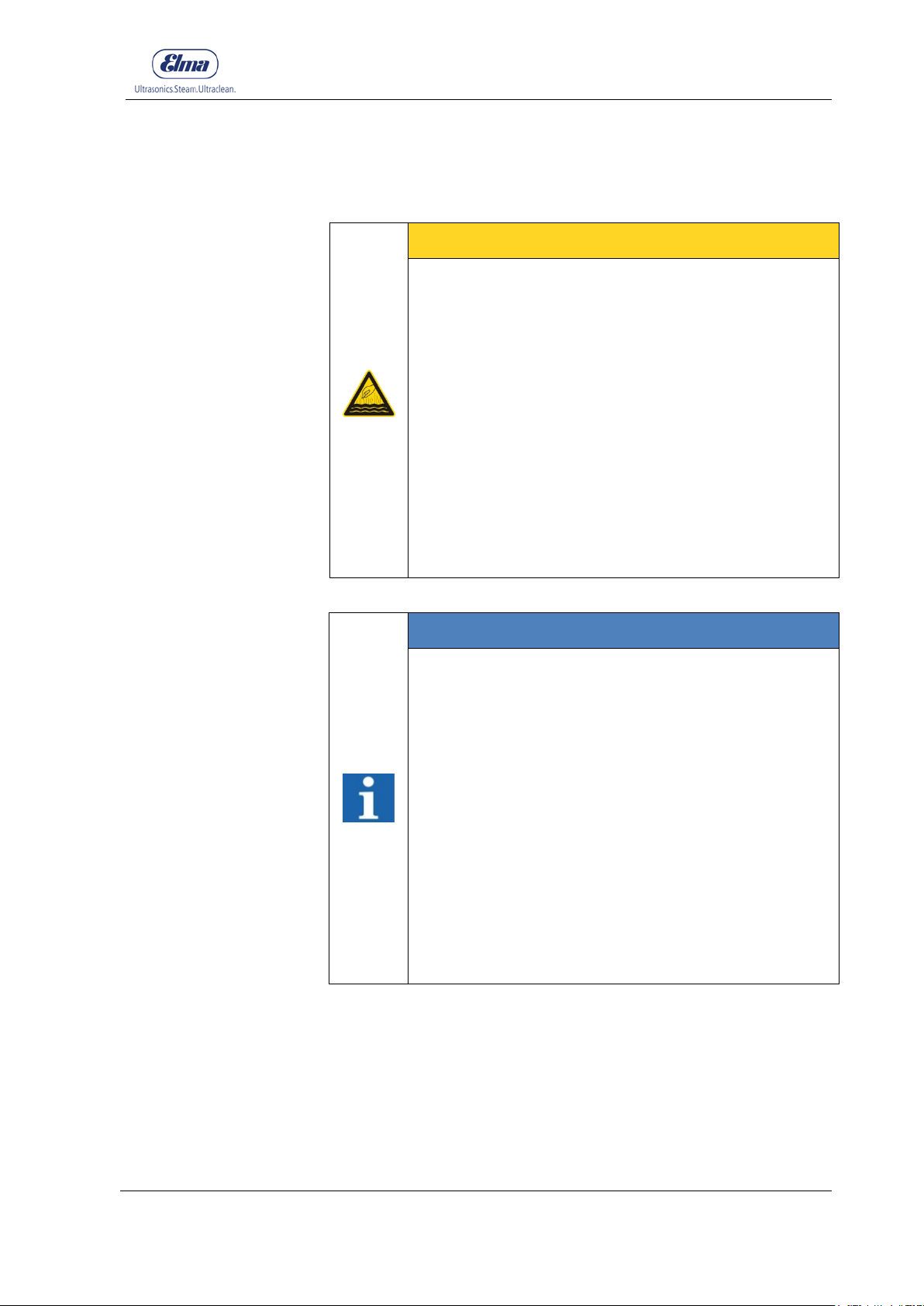
descaled, then the
Service
No operation is possible in
C
A
Warning Tone sounds
every 10 minutes.
(Descale) (C)
flas hes orange
Warning (A)
illuminates as
red
the function soft or strong
Automatic shut-down of the
heating (safety shut-down)
Only after the descaling has
been performed is it
possible to reactivate the
steam operation.
BA_Elmasteam_8_Vers.07.2016 © Elma Schmidbauer GmbH
Page 45
45
on the handpiece or on the fixed nozzle.
level minimum is achieved
Let the heated up
l down
first
6 Device filling/emptying
Device filling/emptying
device coo
CAREFUL
Escaping steam!
Risk of scalding!
• Cool down the device before opening.
• Open the pressure tank screw cap only in
depressurised units. Observe the gauge display
(Figure 6-D)! The device remains under pressure
as long as one segment is illuminated on the value
scale on the gauge.
• Device with residual pressure. The scale on the
pressure gauge indicator illuminates.
Let the steam escape via steam outlet.
• Ensure that the escaping steam will not endanger
people, fixtures or equipment.
• The residual steam pressure must be discharged
INFORMATION
Operating Displays for Filling Level and Warning
• Level (B) flashes: no pump operation possible
(Chapter 8.7)
• Level (B) illuminates: If necessary, top up the
device (filling level between minimum and
maximum) The indicator (B) goes out as soon as
pressure is built up in the device.
• Level (B) does not illuminate: Device is full (filling
level maximum)
• Level (B) illuminates + Warning (A) flashes +
Warning Tone, during the operation soft or strong.
Top up the device (filling level below minimum.)
The display for filling level goes out when the
device is completely filled.
• The warning (A) goes out as soon as the filling
© Elma Schmidbauer GmbH BA_Elmasteam_8_Vers.07.2016
Page 46
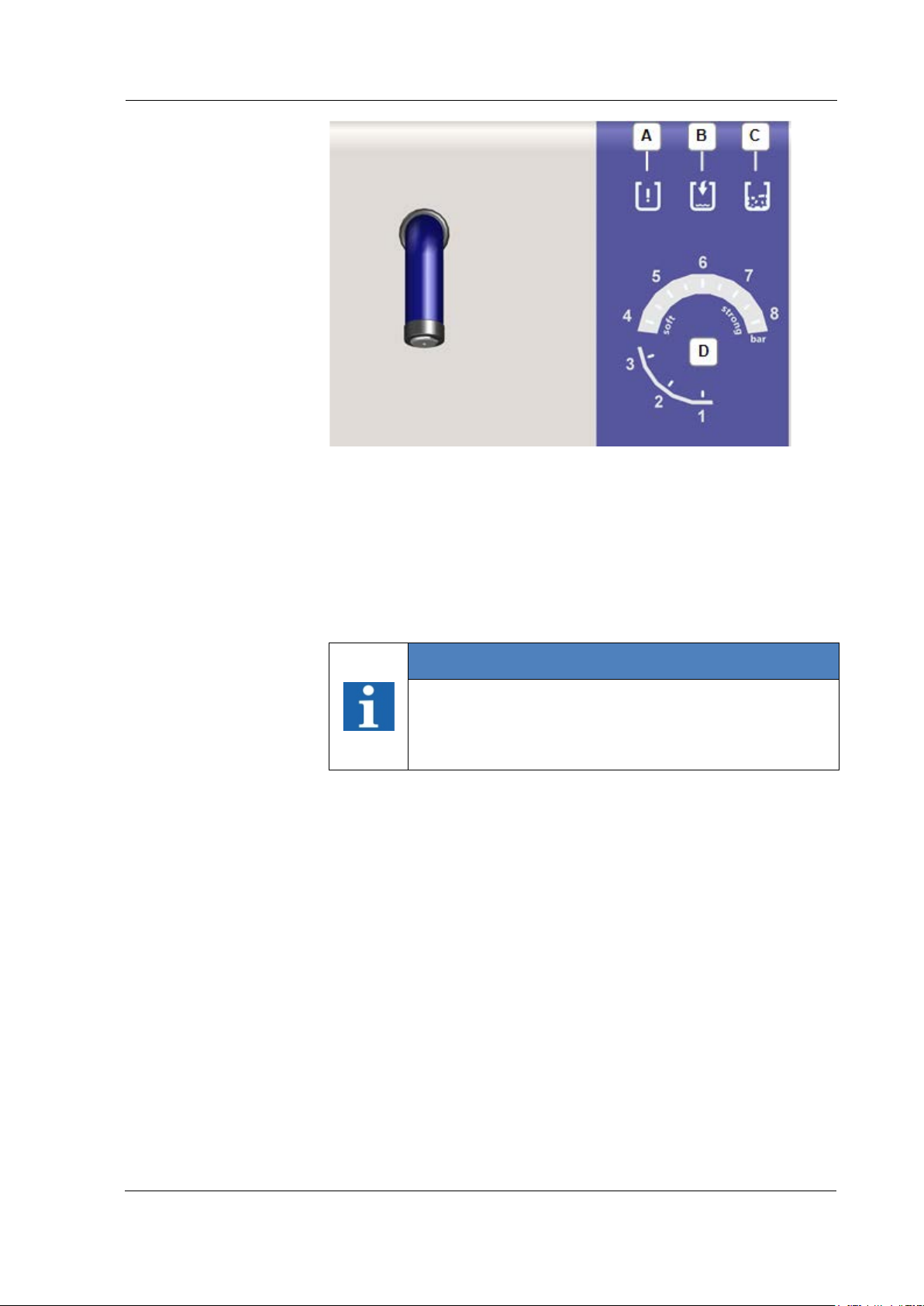
Device filling/emptying
46
illuminated on the value scale on the gauge.
A
B C D
Figure 6: Operating Displays
Warning illuminates/flashes red
Filling Level illuminates/flashes blue
Service (Descaling) - illuminates/flashes orange
Gauge Scale of values illuminates/flashes green
INFORMATION
Operation Displays, Gauge
• Observe the gauge display! The device remains
under pressure as long as one segment is
BA_Elmasteam_8_Vers.07.2016 © Elma Schmidbauer GmbH
Page 47
Device filling/emptying
47
after descaling, (Chapter 8.2).
maintenance intervals and the cleaning results.
calcification levels 1 + 2 must be executed.
6.1 Requirements for the Water Q ual ity
INFORMATION
Requirements for the Water Quality
• Only fill the unit with potable water or DI water.
• If the water conductivity is < 2μS/cm then, at
commissioning (once!),
the pressure vessel must be filled with 1 levelledoff teaspoon of table salt: For this purpose, firstly
dissolve the salt in a glass of water and fill into the
filling hole.
• The salt does not go over into the vapour phase
and thereby remains in the device. Therefore, the
addition is only necessary during commissioning or
INFORMATION
Water Quality
• Preferably operate the device with DI water. The
service life of the device can therefore be
considerably extended.
• Water quality can considerably influence the
6.1.1 Determining the Water Quality
The quality of the water which is utilised will have a decisive influence on
the service life and product safety of the device. The harder the water is,
then the more often the machine must be descaled. Therefore, it is
important to adjust the water hardness.
Measure before commissioning to determine the local water quality with
the accompanying test strips Utilise the "Settings" Table (Figure 7.4.6.1)
to set the programme number for the lime and chlorine content! Settings
(Chapter 7.4.6).
INFORMATION
Measuring the Water Quality
• Utilise the "Setting s" T a ble ( Figure 7.4.6.1) to se t
the programme number for the DI water or
softened water! Settings (Chapter 7.4.6).
• When using DI water or softened water, the de-
© Elma Schmidbauer GmbH BA_Elmasteam_8_Vers.07.2016
Page 48
Device filling/emptying
48
Point 1.
• Fill the device slowly to prevent overfilling.
Prerequisite
Pressure reduction
with operating display
filling level
6.2 Manual Filling
INFORMATION
Pressure-free device
• Commence the filling with Point 2 for press ur e -free
devices. Observe the gauge display! The device
remains under pressure as long as one segment is
illuminated on the value scale on the gauge.
• Always firstly discharge the pressure with heated
up devices! Observe the gauge display, pressure
values illuminate as green when the pressure
vessel is pressurised! Commence the filling with
INFORMATION
The device is switched off and depressurised.
• Observe the maximum filling capacity (Chapter 3.4
Technical Data).
The commissioning was executed (Chapter 4).
The device is switched on at the mains supply switch!
The device is ready for use!
1. Let the remaining steam pressure discharge through the
nozzle. Utilise hereby the function steam outlet (Chapter
7.4.1).
1.1. Device version with manual unit:
1.1.1 Hold the manual unit in a sink or in a bucket until no steam
discharges any more.
1.1.2 Hold down the steam button for 2 seconds to discharge any
residual steam vapour pressure. Steam escapes
permanently. To interrupt, press the steam button again.
1.2 Device version with fixed nozzle:
1.2.1 Position the unit with a fixed nozzle over a sink or suitable
bucket until no more steam discharges.
1.2.2 Hold down the foot switch for 2 seconds to discharge any
residual steam vapour pressure. Steam escapes
permanently. To interrupt, press the foot switch again.
BA_Elmasteam_8_Vers.07.2016 © Elma Schmidbauer GmbH
Page 49
49
vessel during filling.
when damaged or leaking.
Allow to device to
cool down after
up
Filling the pressure
vessel
Observe the
operating displays
Close the pressure vessel
screw cap
1.2.3
Device filling/emptying
CAREFUL
pressure build-
Escaping steam!
Prevent scalding caused by unforeseen vapour
formation during filling!
• Allow the device to cool down after full pressure
discharge for approx. 5 minutes.
• Do not lean over the filling opening of the pressure
2. Slowly open the pressure vessel screw cap as residual steam
can escape laterally from the pressure vessel screw cap
3. Insert the sieve (Figure 6.2.2) from the scope of delivery into
the collection tray.
WARNING
Possible short circuit in the device from the
ingress of water into the housing!
Electric shock, serious injury!
• Refill with water slowly.
• Avoid overfilling. Observe the operating displays.
• Water must not ingress into the ventilation slots of
the device cover.
• Regularly inspect the seal on the pressure vessel
screw cap.
• Replace the seal on the pressure vessel screw cap
4. Refill with wate r slowly.
Ensure that you do not overfill the pressure vessel. Observe
the operating display for the filling level (the display level goes
out when the maximum level has been achieved).
The filling level is displayed on the operation display:
• The operating display warning will go out when the
minimum filling level has been achieved.
• The operating display warning will go out when the
maximum filling level has been achieved.
5. The pressure vessel is completely filled when the operating
display for the filling level goes out.
6. Remove the sieve.
7. Wipe away any overflowing water.
8. Close the pressure tank screw cap manually (hand tight).
© Elma Schmidbauer GmbH BA_Elmasteam_8_Vers.07.2016
Page 50
Device filling/emptying
50
A B C
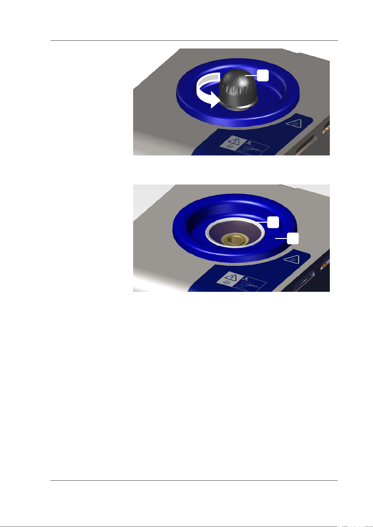
A B C
Figure 6.2.1: Opening/closing the pressure vessel
Open the pressure tank screw cap (in arrow direction)
Figure 6.2.2: Laying the sieve into the collecting tray
Sieve
Collection Tray for overflowing water when filling
BA_Elmasteam_8_Vers.07.2016 © Elma Schmidbauer GmbH
Page 51
Device filling/emptying
51
and the cleaning result will improve.
• Do not utilise the pump for filling an empty device!
application breaks.
Water quality
requirements
A pump ensures the
optimal level
6.3 Automatic Filling wit h P um p (optional)
For the automatic filling, both potable water and completely
desalinated DI water can be used.
INFORMATION
If the water conductivity is < 2μS/cm then, at
commissioning (once!), the device must be added with
1 levelled-off teaspoon of table salt: For this purpose,
firstly dissolve the salt in a glass of water and fill into
the filling hole (A).
• The salt does not go over into the vapour phase
and thereby remains in the device so that the
addition must only be executed for the initial
commissioning, or after descaling the device
(Chapter 7.4.5)..
• Preferably operate the device with desalinated or
softened water.
• For operation with softened or desalinated DI
water, the maintenance intervals will be extended
The pump automatically fills the pressure vessel with the optimum
filling amount of water. There is no waiting time caused by
necessary cooling phases as with the manual filling.
As soon as the water level is lowered in the pressure vessel, then
the pump automatically fills the pressure vessel to the optimum
filling level.
INFORMATION
• The pump is only suitable for refilling the device!
• Intelligent pump control, pump operation during
© Elma Schmidbauer GmbH BA_Elmasteam_8_Vers.07.2016
Page 52
Device filling/emptying
52
measure.
unattended.
• Conductivity must be at least 2 µS/cm.
Prerequisite
Procedural Method
6.3.1 Filling with Fixed-water Connection (option)
CAREFUL
Possible brackish water back flow into the water
supply!
Contamination of potable water!
• Install a backflow prevention system between buildingside water connection and the device.
• The operator is responsible for implementing the
CAREFUL
Possible loosening of the water hose!
Water damage!
• Always close the water supply of the pump on the water
tap after the operation and when the machine is
CAREFUL
Pump damage!
• Only connect the pump to a potable water supply of
drinking water, or preferably to a softening / desalination
plant.
The commissioning was executed. (Chapter 4)
The device is connected to a fixed-water supply. (Chapter 4.4
Installation of a fixed-water supply)
The device is switched on at the mains supply switch!
The device is ready for use!
The pressure vessel is completely filled or filled above the minimum
level.
If the pressure vessel is empty or below the minimum fill level, then fill
the pressure vessel in advance manually with about 2 litres of water
(Chapter 6.2).
1. Open the on-site water tap for the water supply.
2. The automatic filling or refilling starts approximately 30 seconds
after switching on the device.
3.
During the operation, the filling will be regulated via the filling
level monitoring.
BA_Elmasteam_8_Vers.07.2016 © Elma Schmidbauer GmbH
Page 53
Device filling/emptying
53
unit has cooled down.
CAREFUL
Hot vapours/hot liquids
Risk of scalding from open pressure vessel screw cap
• Hot water splashes and evaporates from the filling
opening
• Switch off the device immediately at the mains
switch or unplug the mains supply plug from the
mains supply
• Let the appliance cool down
• Only close the pressure tank screw cap once the
© Elma Schmidbauer GmbH BA_Elmasteam_8_Vers.07.2016
Page 54
Device filling/emptying
54
unit has cooled down.
Prerequisite
Preparation
Procedural Method
6.3.2 Initial Filling with the Ca nister
When there is no pressure pipe connection with potable water
available, then the pump can also be supplied via an external
canister. To do this, only utilise the original accessories from the
manufacturer.
The commissioning was executed. (Chapter 4 Commissioning)
The device is connected to the canister. (Chapter 4.5 Installation
Water connection with canister)
The device is switched on at the mains supply switch!
The device is ready for use!
Fill the pressure vessel in advance manually with about 2 litres of
water (Chapter 6.2 Manual filling).
Fill the canister with potable water or DI water.
1. The automatic filling or refilling starts approximately 30
seconds after switching on the device.
2.
During the operation, the filling will be regulated via the filling
level monitoring.
3.
The operating display for the filling level flashes when the filling
level of the canister is down to the minimum.
4. Fill the canister with the funnel when the operating display
illuminates. The canister can be refilled during operation.
CAREFUL
Hot vapours/hot liquids
Risk of scalding from open pressure vessel screw cap
• Hot water splashes and evaporates from the filling
opening
• Switch off the device immediately at the mains
switch or unplug the mains supply plug from the
mains supply
• Let the appliance cool down
• Only close the pressure tank screw cap once the
BA_Elmasteam_8_Vers.07.2016 © Elma Schmidbauer GmbH
Page 55
55
suitable bucket against detachment!
contact.
6.4 Draining the Device
WARNING
Hot vapours/hot liquids
Injuries caused by scalding!
• Never open the drain cock when an excess
pressure of > 0 up has built up in the pressure
vessel!
• Observe the gauge display! As long as the scale of
values on the gauge is illuminated, then the device
is under pressure!
• Open the pressure tank screw cap slowly!
• The residual water may be hot!
• Wear heat resistant gloves when handling the
maintenance hose!
• Secure the maintenance hose in the sink or
Device filling/emptying
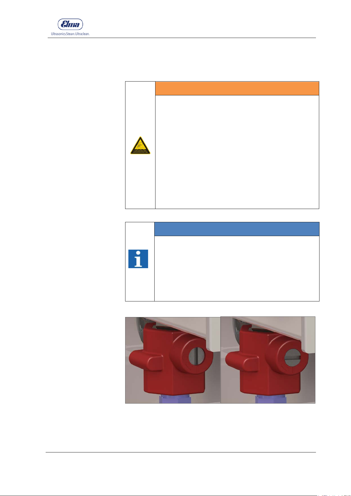
INFORMATION
The ball valve will get hot during operation!
• To avoid that people could be burned in case of
accidental contact with the ball valve and to avoid
that adjacent cables or wires are scorched,
protection against accidental contact has been
installed.
• Do not remove the protection against accidental
© Elma Schmidbauer GmbH BA_Elmasteam_8_Vers.07.2016
Figure 6.4.1: Ball valve Open Figure 6.4.2: Ball valve Closed
Page 56
Device filling/emptying
56
Preparation
Procedural
Method
A
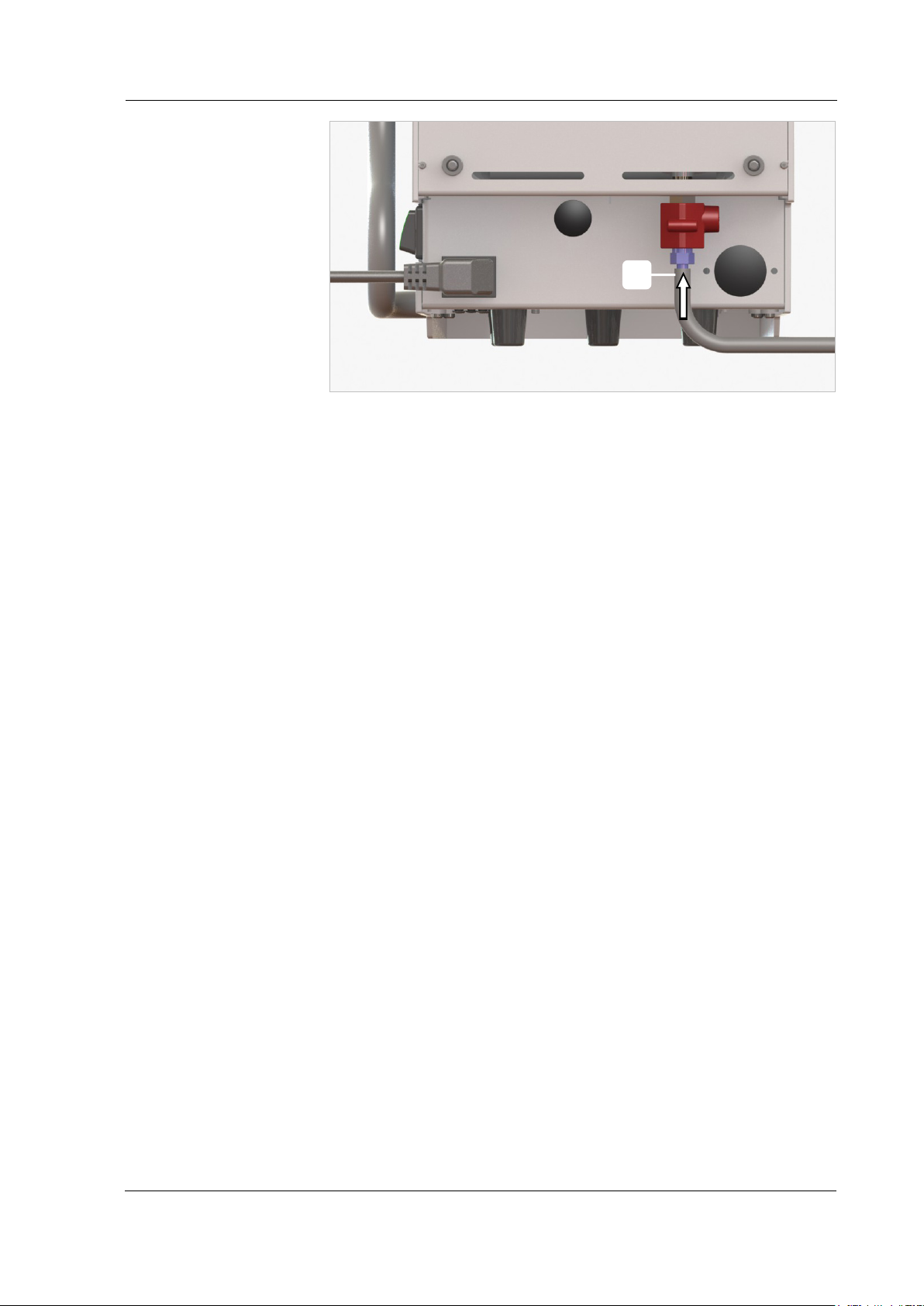
Figure 6.4.3: Connecting the maintenance hose to the ball valve
1. Allow the unit to cool down until it is depressurised (0 bar).
Observe the gauge display. After the drop in pressure is
completed, allow the device to cool down for approx. 5
minutes.
2. Slowly open the pressure tank screw cap (Figure 6.2.1 Device
fill).
3. Connect the maintenance hose (scope of delivery) on the
connection pipe of the ball valve (Figure 6.4.3).
4. Position the other end of the hose in a sink or in a bucket.
Secure the maintenance hose in the sink or suitable bucket
against detachment.
5. Open the ball valve (Figure 6.4.1).
6. Drain the water from the pressure vessel.
7. Connect to the ball valve after emptying (Figure 6.4.2).
BA_Elmasteam_8_Vers.07.2016 © Elma Schmidbauer GmbH
Page 57
57
care.
part thereof.
7 Handling in Operation
WARNING
Hot steam jets!
Injuries caused by burns or scalding!
• During operation of the steam cleaner there cannot
be any unauthorised people in the range of the
steam vapour stream.
• Prevent any dangerous situations that may result
from inadvertent steam outlet.
• Switch off the device during application breaks to
lock.
• Always handle the steam cleaner with extreme
Handling in Operation
WARNING
High temperatures on the surface of the device,
the steam outlet nozzle and the drain cock!
Injuries from burns!
• Only touch the said areas with personal protective
equipment (e.g. protective gloves)
• Allow the unit to cool down before touching any
INFORMATION
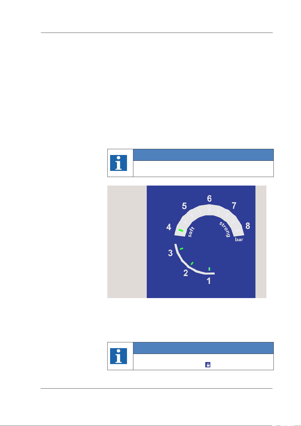
Rotary knob for programme selection:
Turn the rotary knob to select the function and press the
rotary knob to confirm the selection.
The selected programme lights up as blue on the
display segment (point).
The device settings at pre-set to the f actory settings
(Table in Chapter 7.4.6.1 Settings).
INFORMATION
Switch on the device:
After switching on the device, the pressure vessel will
be vented.
Short hissing noises can be repeated several times.
© Elma Schmidbauer GmbH BA_Elmasteam_8_Vers.07.2016
Page 58
Handling in Operation
58
Prerequisites
Pressure vessel is
filled
soft / strong /
steam outlet
Saturated Steam
Ready for Operation
The commissioning was executed (Chapter 4)
The pressure vessel was filled (Chapter 6).
The device is switched on at the mains supply switch!
The device is ready for use!
Set the programme for soft, strong, steam outlet on the
programme se lectio n.
setting for the steam range 4-6 bar (Chapter 7.4.2).
Soft
Strong
Steam Outlet
7.4.1).
Saturated Steam (optional)
setting for the steam range 6-8 bar (Chapter 7.4.3).
for discharging residual steam pressure (Chapter
the saturated steam proportion will
be set by the rotary knob wet/dry (Chapter 7.3)
INFORMATION
The device has been pre-set at the factory. Amending
the factory settings (Chapter 7.4.6 Settings).
Figure 7.1: Gauge
The device has achieved the operating pressure when all the
pressure values illuminate until the operating pressure green. (e.g.
at 4 bar operating pressure, the scale of values illuminates as 1-4
on the gauge (Figure 7.1).
INFORMATION
To prevent accidental steam outlet, turn off the device
during application breaks to
lock (Chapter 7.4.4).
BA_Elmasteam_8_Vers.07.2016 © Elma Schmidbauer GmbH
Page 59
Handling in Operation
59
Holding the work
piece
Approval for
materials to be
cleaned
Distance to the
steam outlet
Cleaning Result
Utilise approved accessories to ensure secure retention of smaller
work pieces. e.g. forceps, sieve etc.
Before commencing any cleaning works, always inform yourself
about whether the work piece, trinket or orthodontic material to be
cleaned is suitable for this cleaning process.
In particular, the thermal and mechanical load has to be taken into
account.
Keep the work piece at least 1 cm away from the nozzle in the
vapour zone.
Control at frequent intervals the cleaning success (visual
inspection) as well as any possible adverse effects on sensitive
surfaces of the cleaning material.
The user is responsible for the control of the cleaning result.
© Elma Schmidbauer GmbH BA_Elmasteam_8_Vers.07.2016
Page 60
Handling in Operation
60
unit in water.
part thereof.
from inadvertent steam outlet.
7.1 Working with the Handpiece
CAREFUL
Hot steam escapes!
Risk of scalding!
• Handpiece
• Escaping steam must not pose a danger to people
or equipment.
• Pay attention to your own safety! Use caution
when the steam outlet is activated.
• Prevent any dangerous situations that may result
from inadvertent steam outlet.
• Never align the steam/compressed air jets at
people.
• Never immerse the plastic handle of the manual
WARNING
High temperatures on the nozzle!
Serious injuries from burns!
• Only touch the said areas with personal protective
equipment (e.g. protective gloves)
• Allow the unit to cool down before touching any
CAREFUL
Hot steam escapes!
Risk of scalding!
• Handpiece
• Escaping steam must not pose a danger to people
or equipment.
• Pay attention to your own safety! Use caution
when the steam outlet is activated.
• Prevent any dangerous situations that may result
INFORMATION
Steam operation steam outlet:
Steam escapes permanently from the steam nozzle
when the steam button is pressed for a minimum of 2
seconds.
To interrupt, press the steam button again.
Or press or turn the rotary knob to interrupt the steam
flow.
BA_Elmasteam_8_Vers.07.2016 © Elma Schmidbauer GmbH
Page 61
Handling in Operation
61
Procedural Method
Compressed air
(option)
B A C
D
INFORMATION
Electrostatic discharge during working with the
handpiece possible (chapter 2.3).
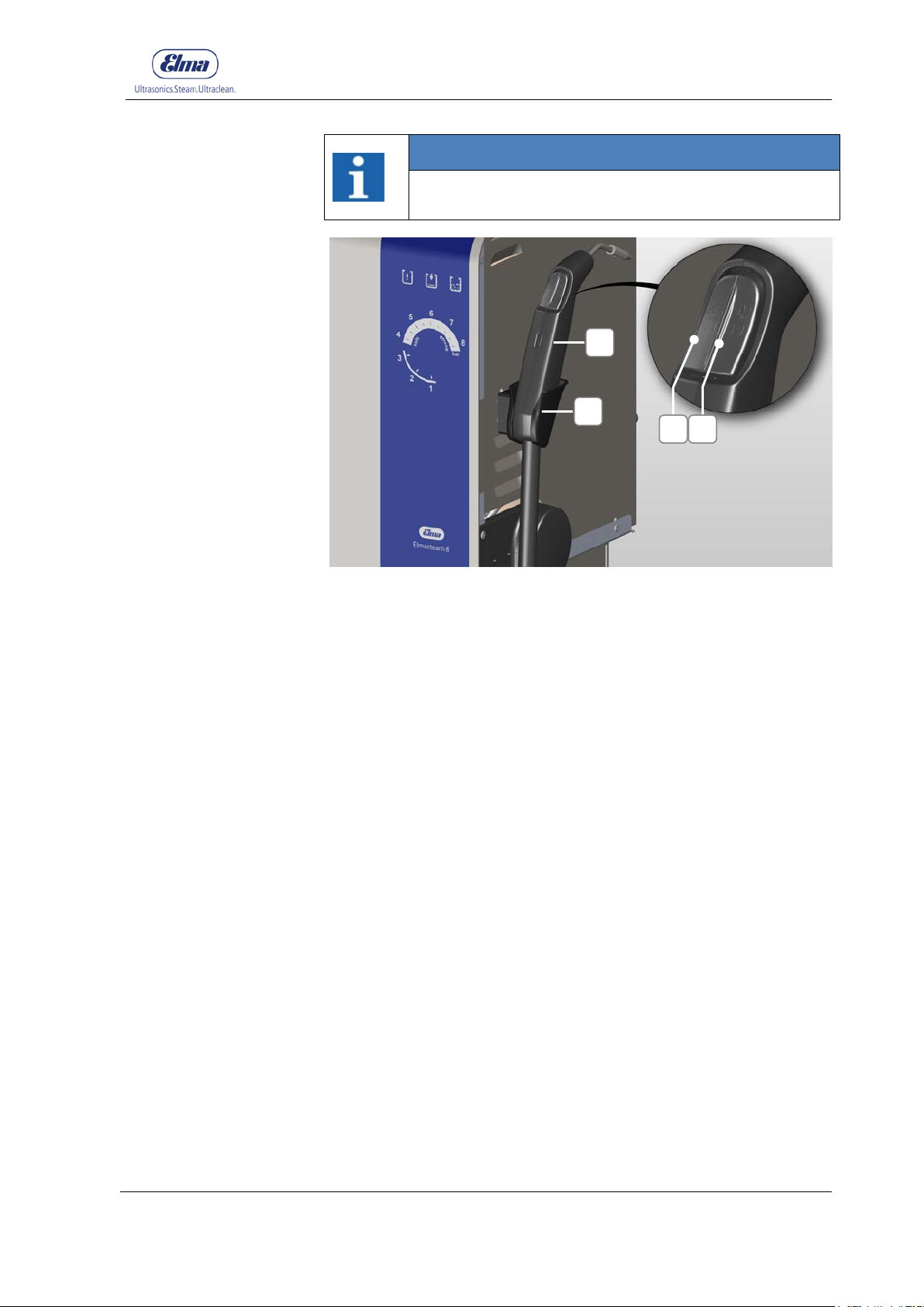
Figure 7.1.1: Handpiece
Steam operation with the handpiece for soft, strong, steam outlet
or saturated steam.
1. Take the handpiece (C) from the manual unit holder (D).
2. Align the manual unit into an appropriate bucket or sink to
discharge any possible condensate accumulations. Briefly
press the steam button (A) until steam appears.
3. Press steam button (A) to start the steam function. Both
buttons (A+B) can be pressed for the steam function. The
handle of the manual unit heats up slightly.
4. Moisten the material to be cleaned with steam from the
handpiece (C).
5. Release steam button (A) or (A + B) to finish the steam
function.
6. Hang the handpiece back into the manual unit holder.
7.
For devices with compressed air connection (optional).
8.
Press the compressed air button (B) to start the compressed
air function.
9.
Blow the material to be cleaned with compressed air.
10.
Release the compressed air button (B) to finish the
compressed air function.
© Elma Schmidbauer GmbH BA_Elmasteam_8_Vers.07.2016
11. Hang the handpiece (C) back into the manual unit holder (D).
Page 62
Handling in Operation
62
from inadvertent steam outlet.
part thereof.
7.2 Working with the Fixed Nozzl e
CAREFUL
Hot steam escapes!
Risk of scalding!
• Fixed Nozzle
• Escaping steam must not pose a danger to people
or equipment.
• Pay attention to your own safety! Use caution
when the steam outlet is activated.
• Prevent any dangerous situations that may result
WARNING
High temperatures on the nozzle!
Serious injuries from burns!
• Only touch the said areas with personal protective
equipment (e.g. protective gloves)
• Allow the unit to cool down before touching any
INFORMATION
Steam operation steam outlet:
Steam escapes permanently from the steam nozzle
when the foot switch is pressed for a minimum of 2
seconds.
To interrupt, press the foot switch again.
Or press or turn the rotary knob to interrupt the steam
flow.
BA_Elmasteam_8_Vers.07.2016 © Elma Schmidbauer GmbH
Page 63
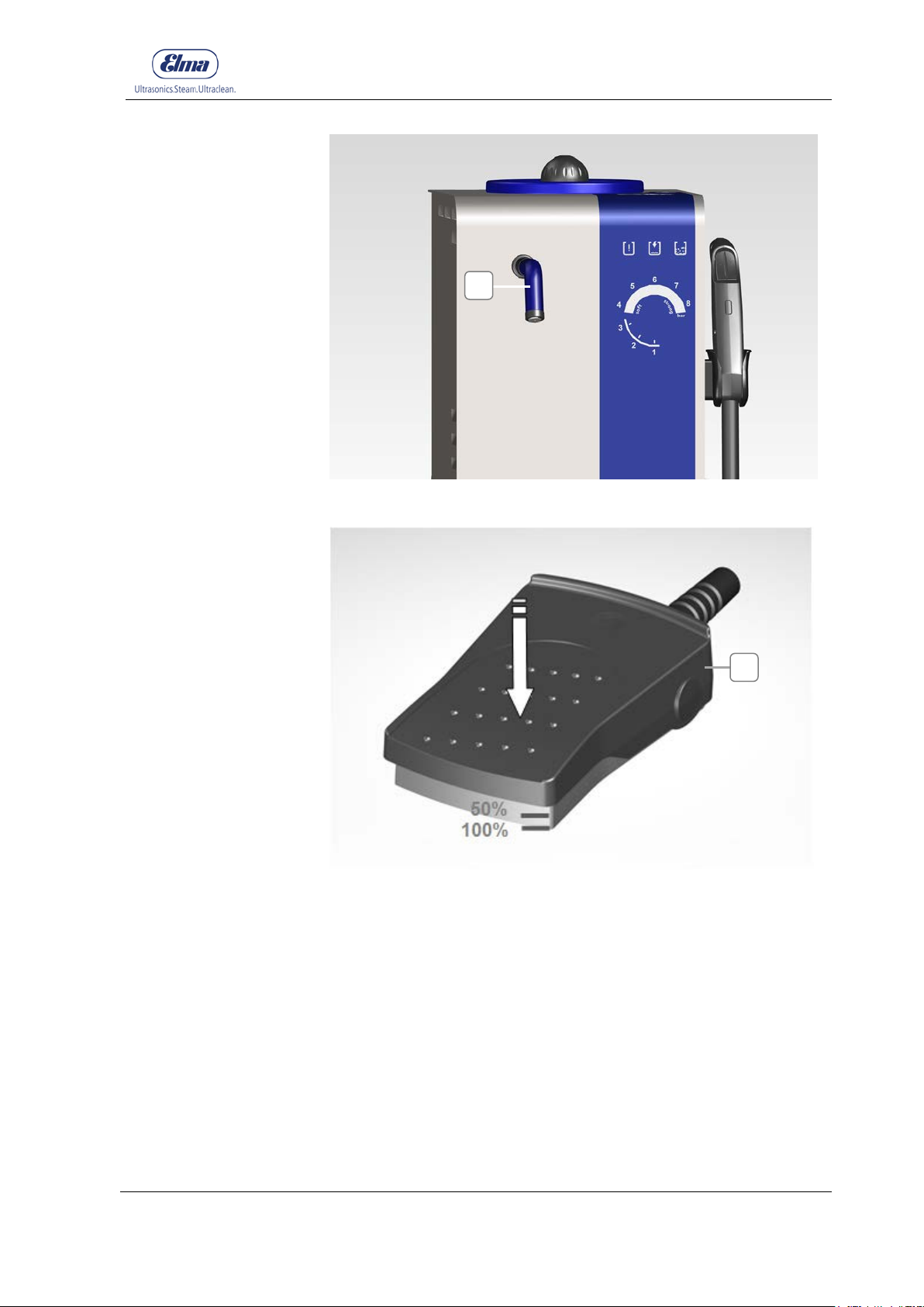
63
Procedural Method
A
B
Figure 7.2.1: Fixed Nozzle
Handling in Operation
© Elma Schmidbauer GmbH BA_Elmasteam_8_Vers.07.2016
Figure 7.2.2: Foot Switch
Steam operation with the fixed nozzle for soft, strong, steam outlet.
1. Hold a suitable bucket under the fixed nozzle (7.2.1-A) to
drain off any possible condensate water. Briefly press the
foot switch (7.2.2-B) until steam exits.
2. Press the foot switch (7.2.1-B) to start the steam function.
3. Moisten the material to be cleaned with steam from the
fixed nozzle (7.2.1-A).
4. Release the foot switch (7.2.2-B) to finish the steam
function.
Page 64

Handling in Operation
64
Compressed
air (option)
Foot Switch
Switching Position
50% Pressed
100% Pressed
5.
For devices with compressed air connection (optional).
6.
Press the foot switch (7.2.2-B) slightly (50%) to start the
compressed air function.
7.
Blow the material to be cleaned with compressed air.
8.
Release the foot switch (7.2.2-B) to finish the compressed
air function.
The foot switch enables you to control the steam
vapour/compressed air outlet at the fixed nozzle.
There are 2 switching positions available:
Activates compressed air to the nozzle.
Activates steam to the nozzle.
BA_Elmasteam_8_Vers.07.2016 © Elma Schmidbauer GmbH
Page 65
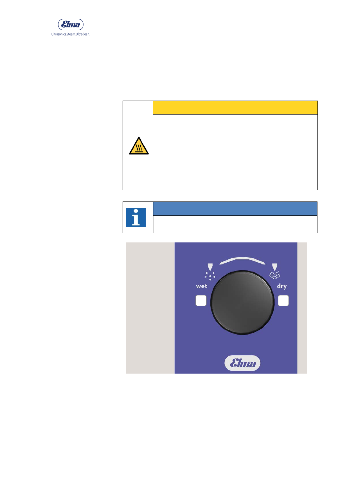
Handling in Operation
65
from inadvertent steam outlet.
Saturated steam is available on the handpiece
wet (A)
dry (B)
7.3 Operation with Saturated Steam wet/dry (option for device with pump)
CAREFUL
Hot steam escapes!
Risk of scalding!
• Handpiece
• Escaping steam must not pose a danger to people
or equipment.
• Pay attention to your own safety! Use caution
when the steam outlet is activated.
• Prevent any dangerous situations that may result
INFORMATION
(Chapter 7.1 Working with the handpiece).
A B
Figure 7.3: Setting the saturated steam function
The percentage of moisture in the saturated steam is set by
utilising the rotary knob wet/dry.
Regulating the saturated steam proportion for the mixing ratio
of the saturated steam function.
Regulating the dry steam proportion for the mixing ratio of the
saturated steam function.
© Elma Schmidbauer GmbH BA_Elmasteam_8_Vers.07.2016
Page 66
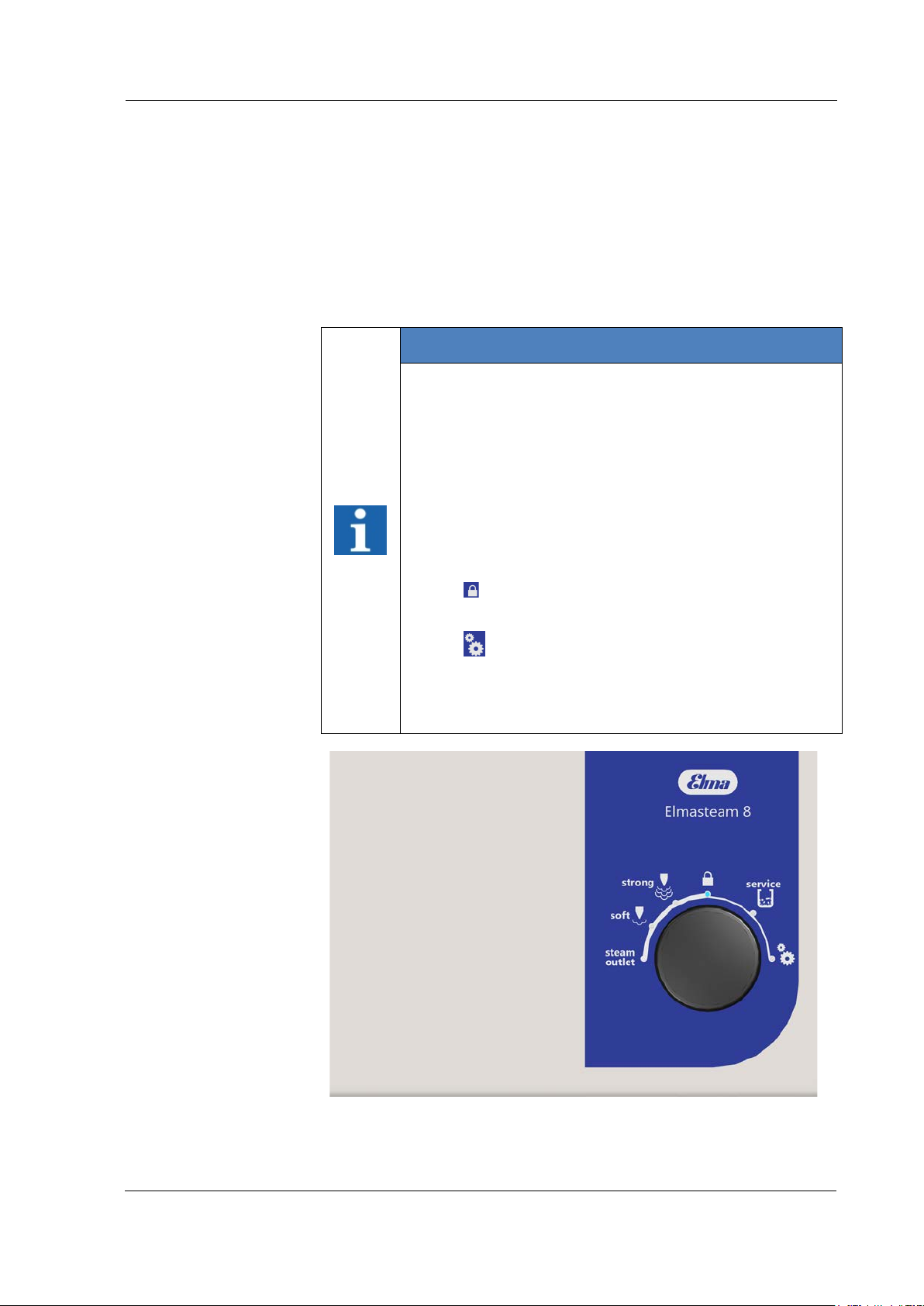
Handling in Operation
66
Procedural Method
1. Turn the rotary knob completely in the direction
100% saturated steam.
2. Turn the rotary knob completely in the direction
100% dry steam.
3. Turn the rotary knob during the steam operation towards
wet or dry to adjust the mixing ratio.
7.4 Programme Selection
INFORMATION
Rotary knob for programme selection:
Turn the rotary knob to select the function and press the
rotary knob to confirm the selection.
The selected programme lights up as blue on the
display segment (point).
The programmes:
• steam outlet
• soft
• strong
•
lock
• service (descaling)
wet
dry
(A) for
(B) for
•
Setting
are described in the following chapters.
The device is pre-set to the factory settings (Table
Chapter 7.4.6.1 Settings).
Figure 7.4: Rotary knob, programme selection
BA_Elmasteam_8_Vers.07.2016 © Elma Schmidbauer GmbH
Page 67
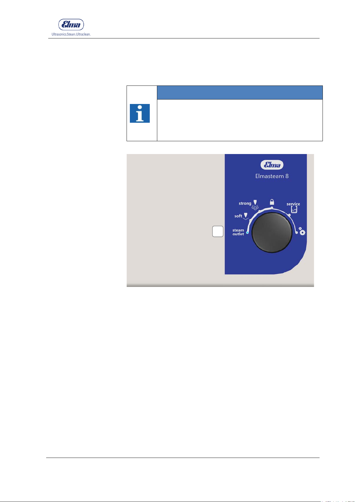
67
Procedural
Method
7.4.1 Selecting the Steam Outlet
INFORMATION
Steam escapes permanently from the steam nozzle
when the steam button/foot switch are pressed for a
minimum of 2 seconds. Press the steam button/foot
switch again to interrupt the process. You can also
press the rotary knob to interrupt the process.
Handling in Operation
A
Figure 7.4.1: Programme selection, steam outlet
Function for discharging residual steam pressure. Before opening
the pressure vessel screw cap e.g. for manual refilling, before
emptying.
1. Set the rotary knob to
steam outlet
.
2. Press the rotary knob to confirm.
3. Discharge the residual steam pressure on the fixed nozzle
or handpiece.
4. Please observe the Chapter 7.1 Working with the
handpiece or the Chapter 7.2 Working with the fixed
nozzle.
© Elma Schmidbauer GmbH BA_Elmasteam_8_Vers.07.2016
Page 68
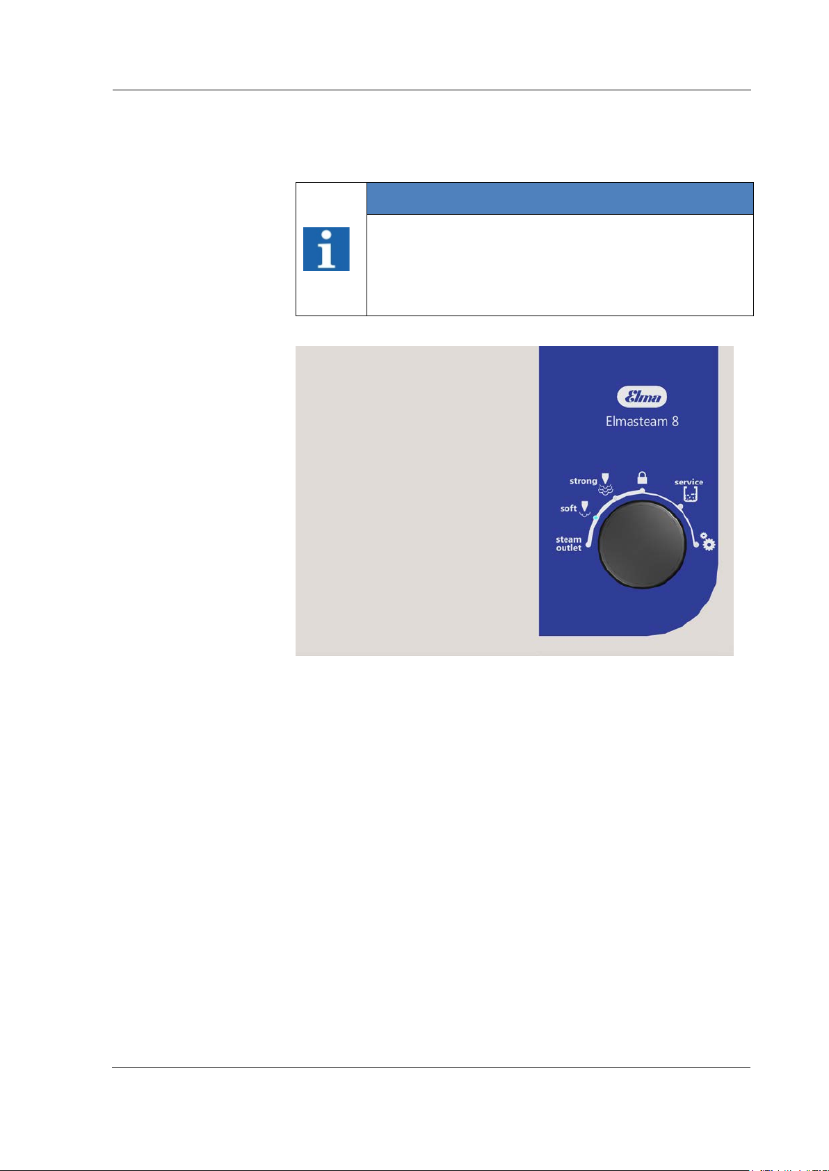
Handling in Operation
68
Procedural
Method
7.4.2 Selecting Soft
INFORMATION
The selected programme lights up as blue on the
display segment (point).
The setting for the steam range soft is pre-set at the
factory and can be amended in the programme
settings (Chapter 7.4.6 Settings).
Figure 7.4.2: Programme selection, soft
For use in the steam range of 4 - 6 bar (adjustable in 0.5 bar
increments).
1. Set the rotary knob to
soft
.
2. Press the rotary knob to confirm.
3. Utilise the steam via the fixed nozzle or the handpiece.
4. Please observe the Chapter 7.1 Working with the
handpiece or the Chapter 7.2 Working with the fixed
nozzle.
BA_Elmasteam_8_Vers.07.2016 © Elma Schmidbauer GmbH
Page 69
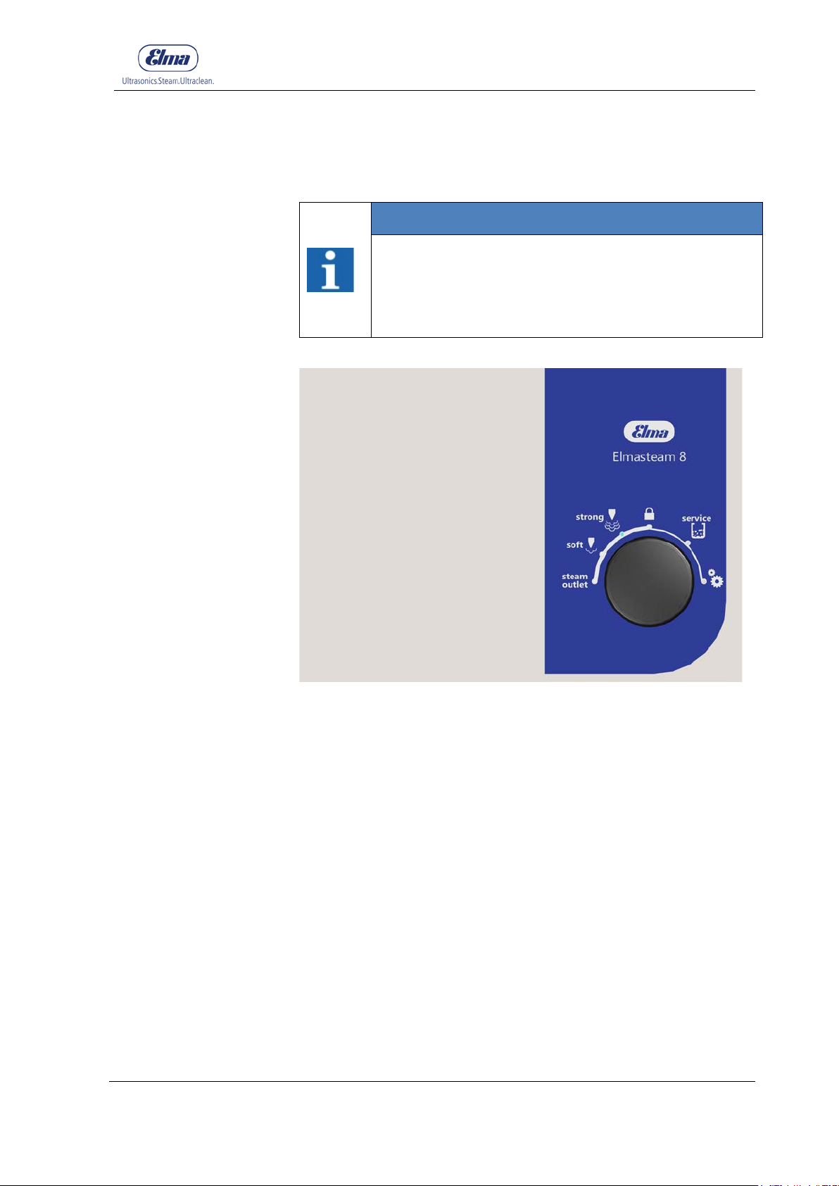
69
Procedural
Method
7.4.3 Selecting strong
INFORMATION
The selected programme lights up as blue on the
display segment (point).
The setting for the steam range strong is pre-set at
the factory and can be amended in the programme
settings (Chapter 7.4.6 Settings).
Handling in Operation
Figure 7.4.3: Programme selection, strong
For use in the steam range of 6 - 8 bar (adjustable in 0.5 bar
increments).
1. Set the rotary knob to
strong
.
2. Press the rotary knob to confirm.
3. Utilise the steam via the fixed nozzle or the handpiece.
4. Please observe the Chapter 7.1 Working with the
handpiece or the Chapter 7.2 Working with the fixed
nozzle.
© Elma Schmidbauer GmbH BA_Elmasteam_8_Vers.07.2016
Page 70
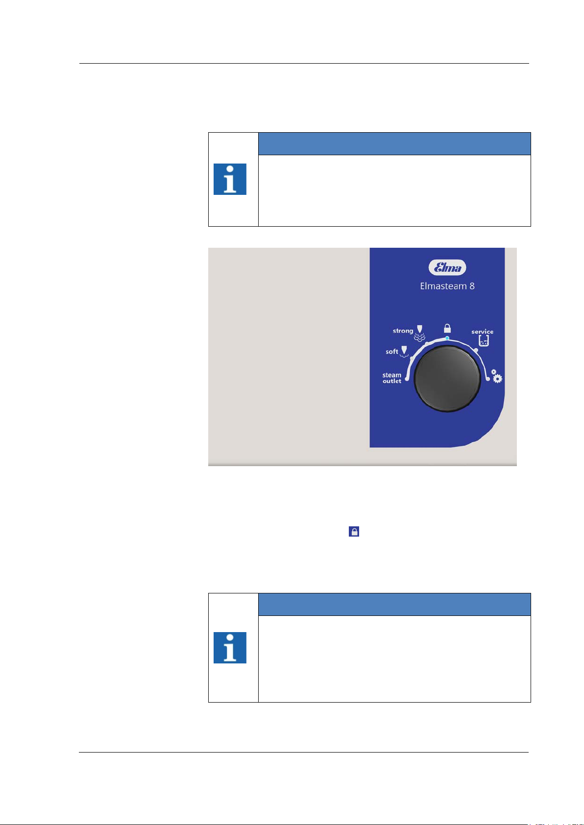
Handling in Operation
70
Procedural
Method
Automatic
7.4.4 Selecting lock
INFORMATION
The selected programme lights up as blue on the
display segment (point).
The time setting for the function lock is pre-set at the
factory and can be amended in the programme
settings (Chapter 7.4.6 Settings).
Lock
Figure 7.4.4: Program selec tion lock
Utilise the function lock for application pauses, to avoid accidental
steam discharges.
1. Set the rotary knob to
lock.
2. Press the rotary switch to confirm.
3. The steam button and foot switch are deactivated.
INFORMATION
The device switches automatically to lock after the set
time has expired.
The steam application is ready for use once you have
selected the soft, strong or steam outlet programmes.
After the interval time to eco, the pressure reduces to
3 bar (Chapter 7.4.7 Settings).
BA_Elmasteam_8_Vers.07.2016 © Elma Schmidbauer GmbH
Page 71
71
• The selected programme lights up as blue on the
descaling process!
Descaling with DI water and softened water
omitted.
potable water or DI water for descaling.
7.4.5 Service (Descaling)
INFORMATION
display segment (point).
• The programme service (descaling) can only be
started when the device is depressurised!
• The gauge displays the descaling steps 1-8. The
current de-calcifying step illuminates or flashes as
green on the gauge.
• The descaling programme cannot be interrupted!
Duration approx. 2.5 hours (including reaction
time).
• Descale the device when the operating display
Service illuminates on the device (Chapter 3.6.3
Operating Displays). 3 warning levels request
descaling. A safety shut-down of the heating will
be executed when you do not perform the
Handling in Operation
INFORMATION
• When you operate the device with DI water or
softened water, descaling is ended after the
descaling step 2 Preparation Step 3 "citric acid" is
WARNING
Hot steams / Hot liquids
Risk of scalding from steam!
• Only open the pressure vessel screw cap when the
device is depressurised!
• Allow the pressure vessel to cool down before
opening the pressure vessel screw cap!
• Observe the pressure gauge (Figure 7.4.5.2)! The
device remains under pressure as long as one
segment is illuminated on the value scale on the
gauge.
• The residual water may be hot!
• Wear heat resistant gloves when handling the hose
• Only utilise pure citric acid as 3% to 1.5 litres of
© Elma Schmidbauer GmbH BA_Elmasteam_8_Vers.07.2016
Page 72
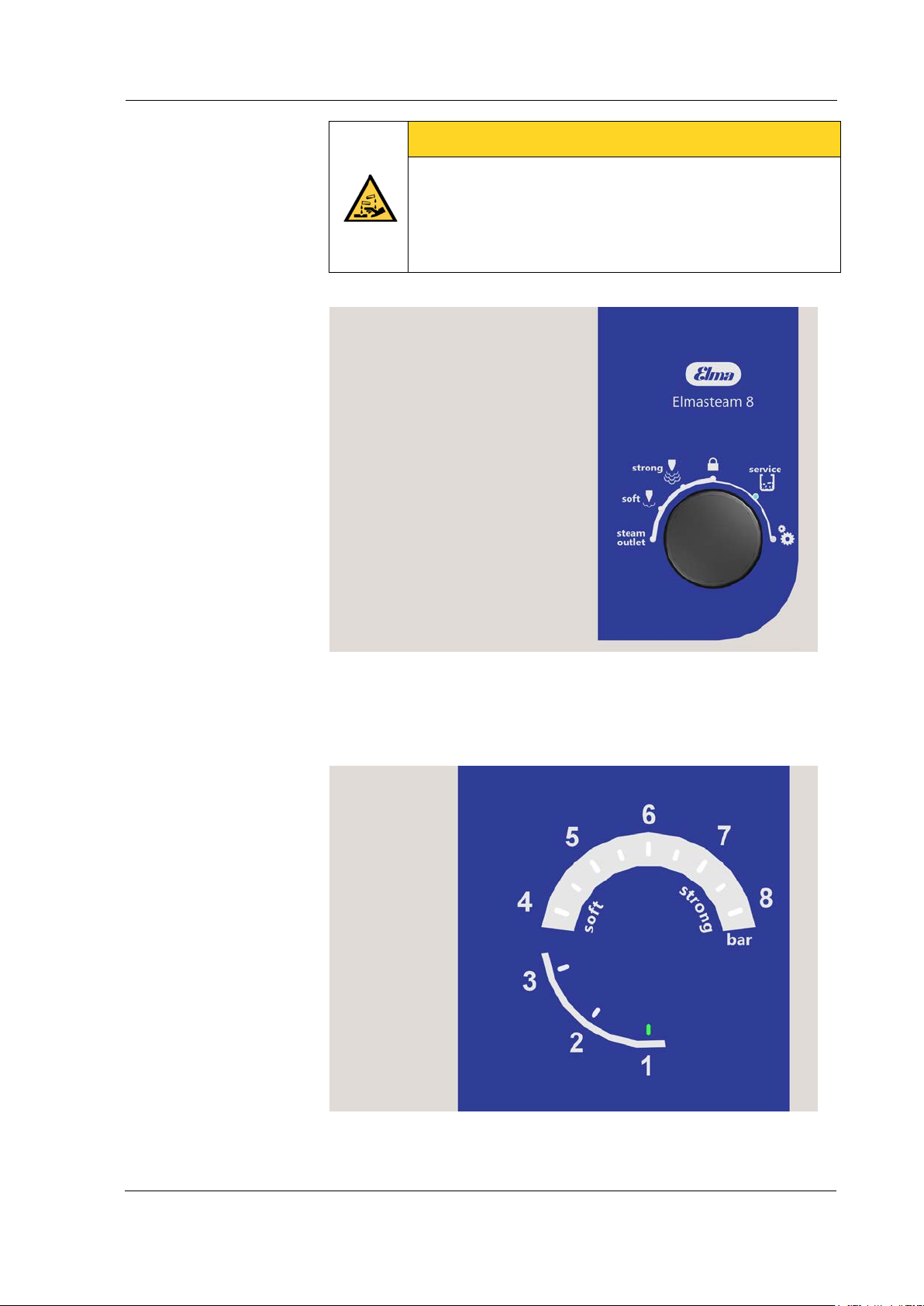
Handling in Operation
72
potable water or DI water for descaling processes!
CAREFUL
Risk of injury!
Injuries can be caused by chemical burns on the skin!
• Never fill chemicals into the device!
• Only utilise pure citric acid as 3% in 1.5 litres of
Figure 7.4.5.1: Rotary knob programme selection, service
Utilise the programme service when you want to descale the
device. You require the flushing set and the maintenance hose
(provided accessories) for descaling.
Figure 7.4.5.2: Gauge display descaling 1-8
BA_Elmasteam_8_Vers.07.2016 © Elma Schmidbauer GmbH
Page 73
Handling in Operation
73
Preparation
Procedural Method
1. Connect the maintenance hose to the ball valve (Figure
6.4.3).
2. Place the prepared flushing set (provided accessory). Also
refer to Chapter 8.2 Rinsing the pressure vessel!
3. Dissolve 3%
of pure citric acid
in 1.5 litre of potable water
or ID water. Fill therefore 1.5 litres of water into a
measuring cup and dissolve in 45 g of pure citric acid (3
heaped tablespoons).
1. Set the rotary knob (Figure 7.4.5.1) to
service
.
2. Press the rotary knob 2 seconds to confirm.
The
descaling step 1
on the gauge (Figure 7.4.5.2)
illuminates as green.
3. Open the pressure vessel screw cap (Figure 6.2.1 Manual
filling).
4. Drain the device completely via the ball valve (Chapter 6.4
Draining).
5. Press the rotary knob to continue with the
.
2
descaling step
The
descaling step 2
on the gauge (Figure 7.4.5.2)
illuminates as green.
6. Subsequently rinse the device with the rinsing set until no
more lime deposits are flushed out (Chapter 8.2 pressure
vessel).
7. Press the rotary knob to continue the
The
descaling step 3
on the gauge illuminates as
descaling step 3
.
green.
8. Close the ball valve (Chapter 6.4 Draining).
9. Fill the descaling agent (pure citric acid 3% to 1.5 litres of
potable water) through the filler opening in the device
(Chapter 5.2 Manual filling).
10. Close the pressure tank screw cap.
11. Press the rotary knob to continue the
The
descaling step 4
on the gauge flashes green.
descaling step 4
.
The device heats up (warm-up time).
The
descaling step 5
on the gauge illuminates as
green (warm up time is completed).
© Elma Schmidbauer GmbH BA_Elmasteam_8_Vers.07.2016
Reaction time! Duration, approximately 2 hours.
Page 74
Handling in Operation
74
Recommendat
ion
INFORMATION
We recommend to let the solution react overnight. You
can switch off the device during the reaction time. The
pressure will be dissipated in the pressure vessel
overnight. If the device is switched on after the
reaction time, then the gauge automatically switches
to descaling step 6 The prerequisite hereby is that the
pressure vessel is depressurised!
The
descaling step 6
green.
12. Open the pressure vessel screw cap (Figure 6.2.1 Manual
filling).
13. Drain the device completely via the ball valve (Chapter 5.4
Draining).
14. Press the rotary knob to continue with the
.
7
The
descaling step 7
green.
on the gauge illuminates as
descaling step
on the gauge illuminates as
15. Close the ball valve (Chapter 6.4 Draining).
16. Fill the device with potable water or DI water* (Chapter 6.2
Manual Filling).
17. Press the rotary knob to continue the
The
descaling step 8
on the gauge illuminates as
descaling step 8
.
green.
18. Drain the device completely via the ball valve (Chapter 6.4
Draining).
19. Press the rotary knob to exit the descaling process.
The function
descaling automatically to
illuminates. The device switches after
lock
(Chapter 7.4.4).
lock
INFORMATION
* Preferably operate the device with DI water.
If the water conductivity is < 2μS / cm, then add 1
levelled-off teaspoon of table salt with the initial
commissioning and after descaling. Dissolve the salt in
1 glass of water and fill it via the filling opening into the
device.
BA_Elmasteam_8_Vers.07.2016 © Elma Schmidbauer GmbH
Page 75
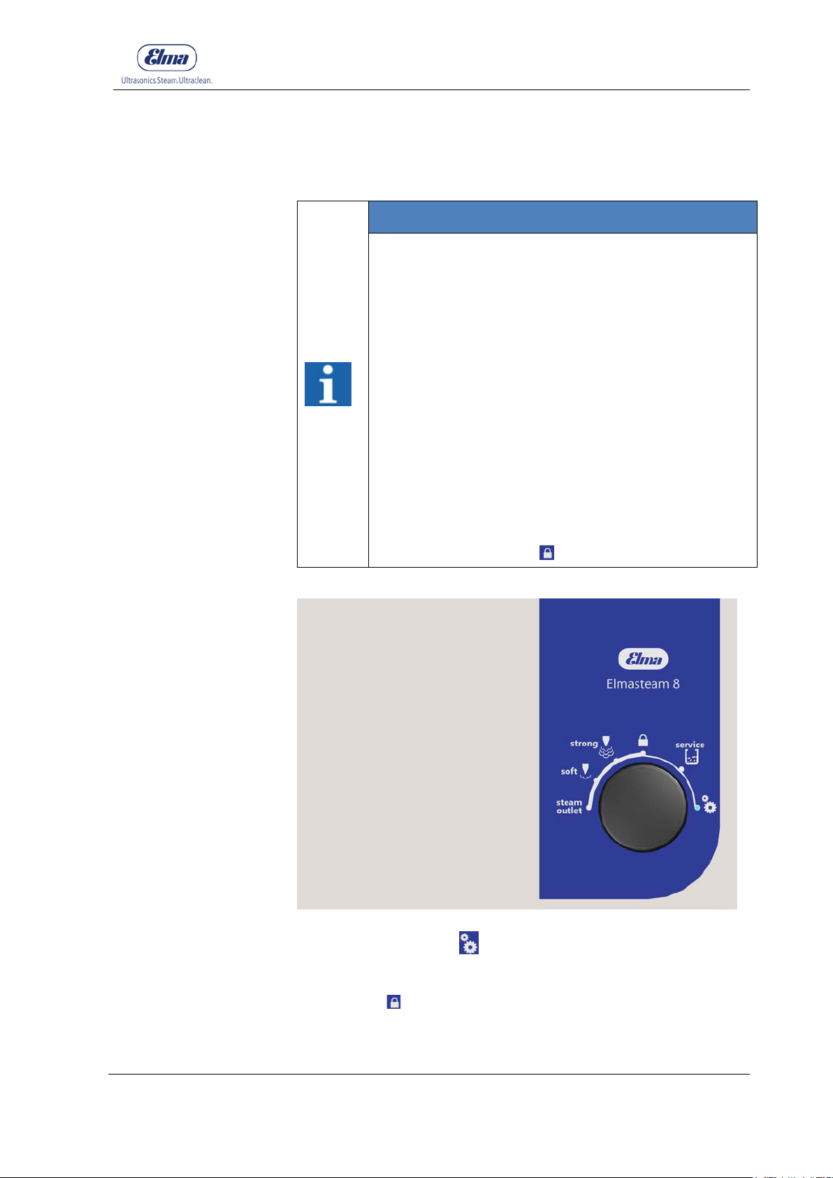
75
7.4.6 Settings
Handling in Operation
INFORMATION
The selected programme lights up as blue on the
display segment (Point).
Settings for the following programmes are displayed
on the pressure gauge:
1=soft,
2=strong,
3=time to lock
4=time to eco,
5=water hardness (lime),
6=chlorine content and
8=factory setting
The device has been pre-set at the factory. The
factory settings can be amended. Utilise the table
(Chapter 7.4.6.1 Settings) for this.
After every adjustment, or after 45 seconds, the device
switches to the function
lock.
Figure 7.4.6.1: Programme selection, settings
Use the programme for
the table (Chapter 7.4.6.1 Settings) for this. Turning the rotary
knob via settings or steam outlet away, then the device will
switch to the
lock function.
© Elma Schmidbauer GmbH BA_Elmasteam_8_Vers.07.2016
settings to amend the settings. Utilise
Page 76
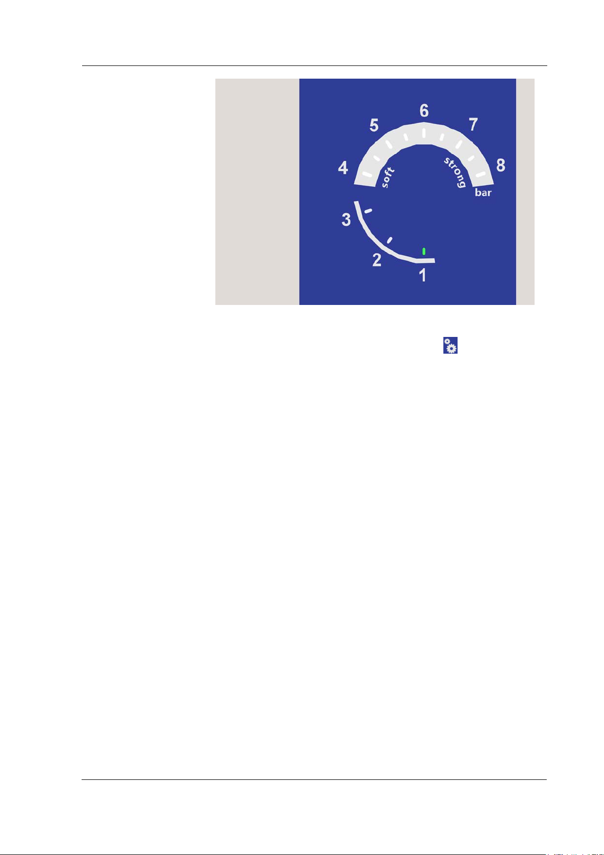
Handling in Operation
76
Procedural Method
Figure 7.4.6.2: Gauge display, settings programme 1-8
1. Set the rotary knob (Figure 7.4.6.1) on
settings.
2. Press the rotary knob (Figure 7.4.6.1) for 2 seconds to
confirm.
To change the device settings, utilise the table for
settings (Chapter 7.4.6.1 Settings)!
3. The scale of values 1 (adjust steam to
) flashes on the
soft
gauge (Figure 7.4.6 .2).
4. Turn the rotary knob until the scale of values on the
pressure gauge indicates the programme number to be
amended.
Programme numbers:
= Set steam pressure for
1
= Set steam pressure for
2
= Set time for time to
3
= Set time for time to
4
= Set measured
5
= Set measured
6
= Reset to
8
Water hardness * 0-20°dH
chlorine content* 0-200 mg/l
factory default
lock 0-105 minutes
eco* 0-7 hours
4-6 bar
soft
strong
settings
6-8 bar
5. Press the rotary knob to confirm the programme number.
The last value set will be displayed on the gauge.
This value will turn green on the scale of values.
6. Turn the rotary knob to amend the value. The possible
setting is displayed on the pressure gauge by the flashing
values. If you exceed or are under the possible setting
range, then the values will not flash any more. Turn back
BA_Elmasteam_8_Vers.07.2016 © Elma Schmidbauer GmbH
Page 77
77
the rotary knob into the possible range of values until the
values that can be set start to flash again.
7. Press the rotary knob to confirm the set value.
8. Start with
* Time to eco, after a set time between 0-7 hours, then the
set pressure range drops to 3 bar.
* Determine hardness, refer to the information data sheet
"Water Quali ty"
* Determine chlorine content, refer to the data sheet "Water
Quality"
7.4.6.1 Settings
The function
illuminates. The device
lock
switches after setting automatic to
7.4.4).
to assume an additional setting!
1.
Handling in Operation
(Chapter
lock
INFORMATION
The factory setting values are highlighted in grey in the
Table 7.4.6.1.
© Elma Schmidbauer GmbH BA_Elmasteam_8_Vers.07.2016
Page 78
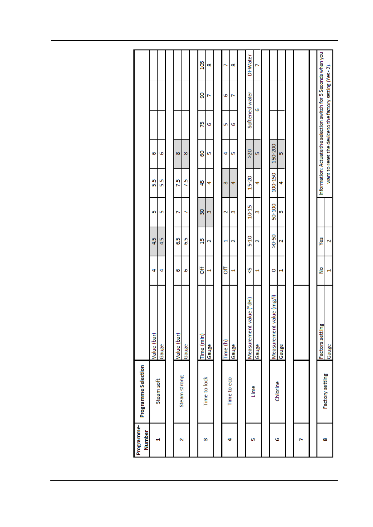
Handling in Operation
78
Table 7.4.6.1 Settings
BA_Elmasteam_8_Vers.07.2016 © Elma Schmidbauer GmbH
Page 79
Safety / Maintenance / Repair Works
79
professional person.
8 Safety / Maintenance / Repair Works
Maintenance works are the responsibility of the user. Damage to
the device caused by not executing maintenance works are not
subject to the manufacturer's warranty!
8.1 Regular Visual Controls
INFORMATION
Visible damage to the unit!
• Inspect for visible damage on the device
components before putting the device into
operation.
• Do not operate the unit when there is any visible
damage.
• Send a defective device for repair to the service
centres of the manufacturer.
• Have damaged components replaced with original
parts from the manufacturer by a qualified
The following components should be checked periodically for signs
of damage:
• T he mains supply cable
• T he foot switch and the electrical supply to the foot switch
• T he steam hose (handpiece)
• O-ring of the pressure vessel screw cap (Chapter 8.3.1)
• O-ring of the nozzle (Chapter 8.3.2)
• Additionally inspect the optional water hose for correct securing
(fixed-water s upply or canister).
© Elma Schmidbauer GmbH BA_Elmasteam_8_Vers.07.2016
Page 80
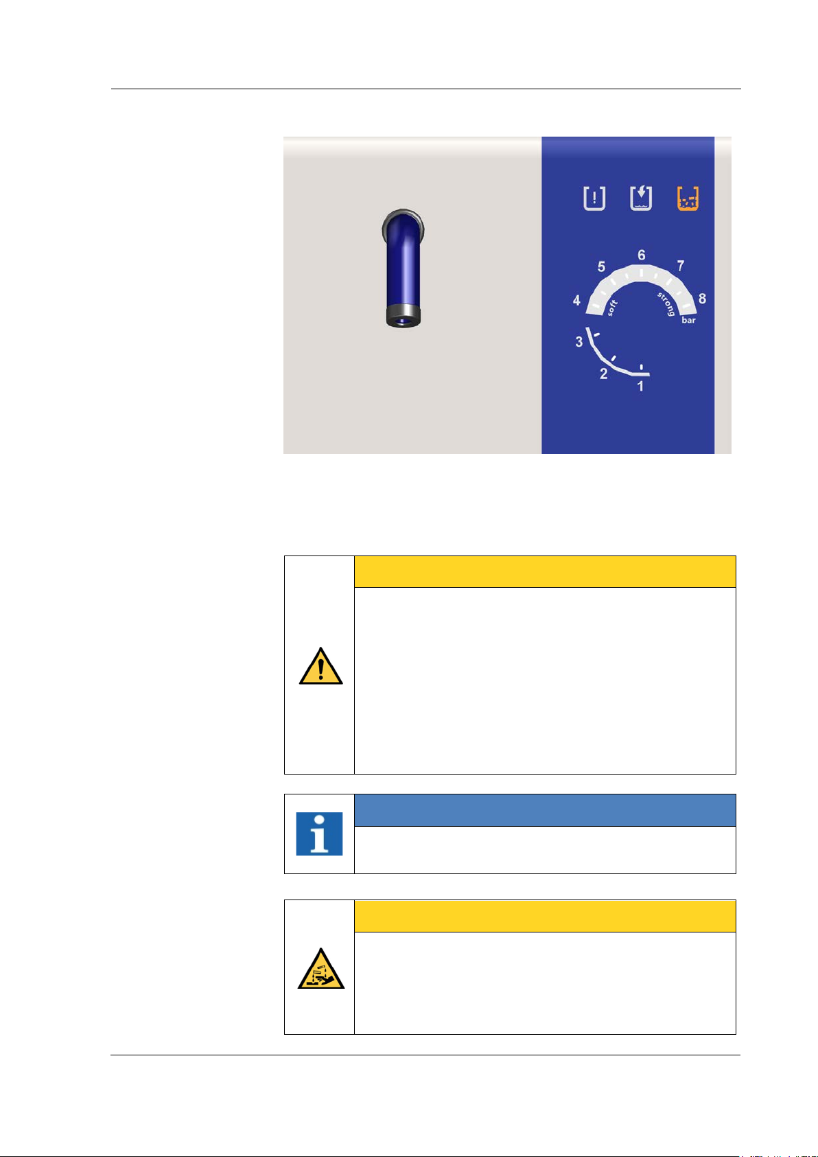
Safety / Maintenance / Repair Works
80
pure citric acid) for descaling!
Intervals
8.2 Flush the Pressure Vessel
Figure 8.2: Operating display, service (descaling)
Depending on the local water quality. The operating display for
service (descaling) signals when descaling is required. The device
must be flushed through in the descaling step 2 (Chapter 7.4.5
Service (descaling).
CAREFUL
Overpressure in the pressure vessel!
Loss of safety function!
• Flush through the pressure vessel (Chapter 7.4.5.
Service/descaling).
• Calcium deposits (in hard calcium content water)
can lead to a loss of the safety function on the
safet y va lve.
• The operator and/or owner is responsible for the
regular flushing in the descaling programme.
INFORMATION
Use the flushing set (Figure 8.2) to flush the pressure
vessel (flushing set included in the scope of delivery).
CAREFUL
Risk of injury!
Injuries can be caused by chemical burns on the skin!
• Never fill chemicals into the device!
• Only utilise potable water or DI water (1.5 l with 3%
BA_Elmasteam_8_Vers.07.2016 © Elma Schmidbauer GmbH
Page 81
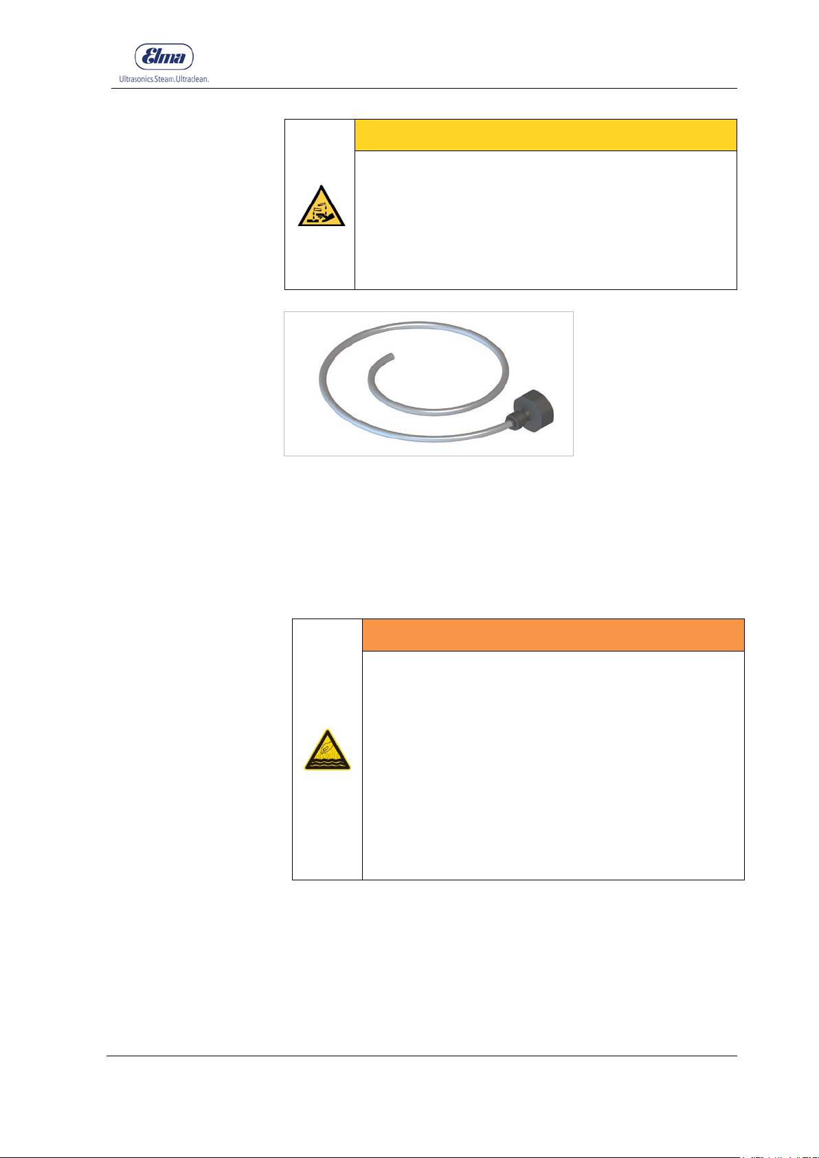
Safety / Maintenance / Repair Works
81
pure citric acid) for descaling!
• Wear heat resistant gloves when handling the hose
Preparation
Procedure for Flushing
CAREFUL
Risk of injury!
Injuries caused by acidic steam!
• Never fill chemicals into the device!
• The material of the pressure vessel can be
damaged by chemicals!
• Only utilise potable water or DI water (1.5 l with 3%
Figure 8.2: Flushing set for connecting to the water tap (3/4")
• Allow the unit to cool down until it is depressurised (0 bar). After
completion of the pressure discharge, the device still needs to
cool down for approx. 5 minutes to avoid spontaneous
formation of steam when flushing.
• Place the f lushing set (Figure 8.2) and the maintenance hose
from the scope of delivery in a position ready for use.
WARNING
Hot steams / Hot liquids
Risk of scalding from steam!
• Only open the pressure vessel screw cap when the
device is depressurised!
• Allow the pressure vessel to cool down before
opening the pressure vessel screw cap!
• Observe the gauge display (Figure 8.2)! The
device remains under pressure as long as one
segment is illuminated on the value scale on the
gauge.
• The residual water may be hot!
1. Open pressure tank screw cap (Chapter 6.2 Filling the
device).
2. Connect the maintenance hose (Figure 8.2.1) to the
connecting mounting on the ball valve.
3. Position the device in such a way that the maintenance hose
hangs into a sink or bucket large enough for this operation and
that the ball valve can be operated.
© Elma Schmidbauer GmbH BA_Elmasteam_8_Vers.07.2016
Page 82
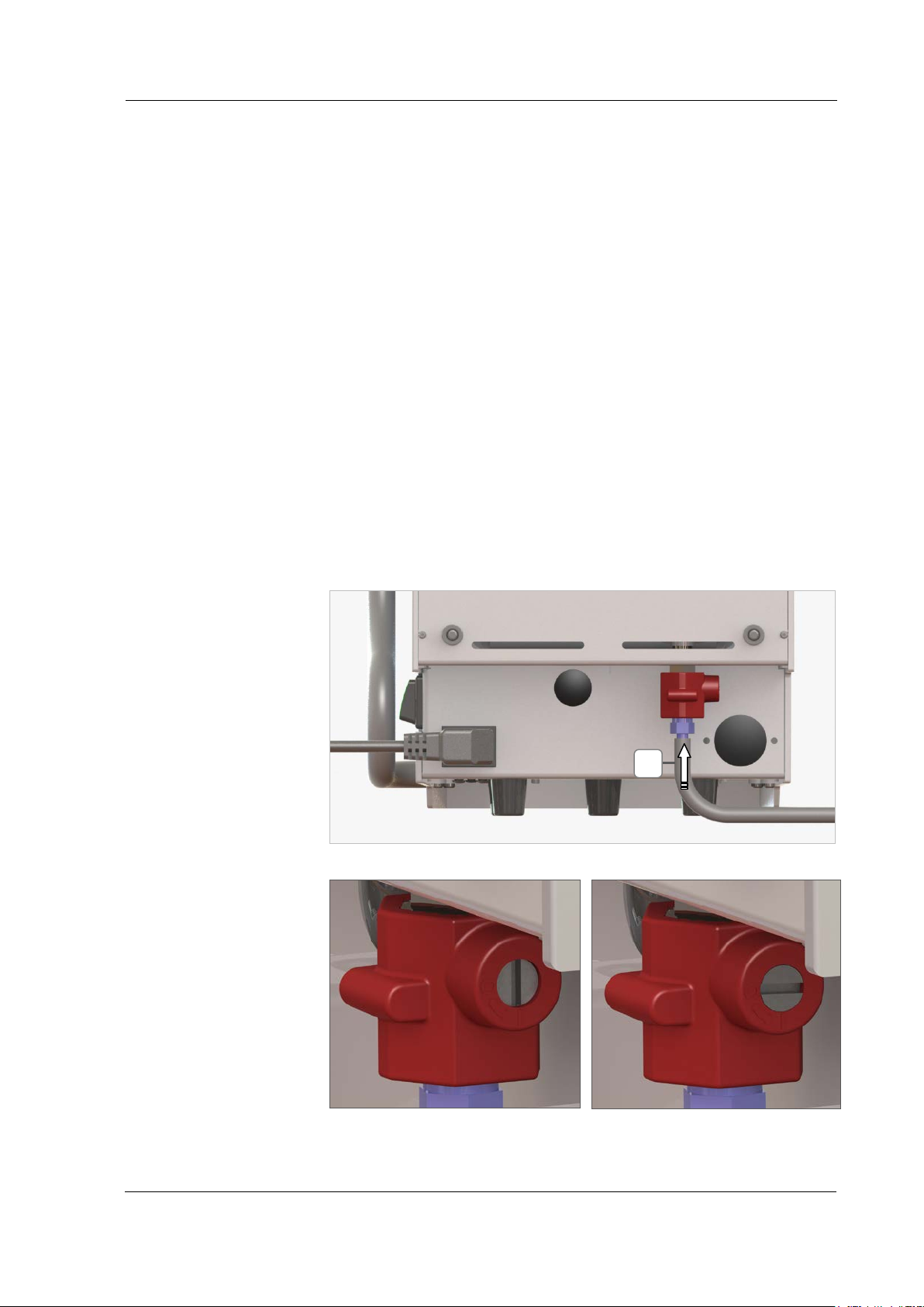
Safety / Maintenance / Repair Works
82
Figure 8.2.2: Ball valve Open
Figure 8.2.3: Ball valve Closed
A
4. Open the ball valve with a screwdriver (Figure 8.2.2) and
initially drain off any residual water which may be in the
device.
5. Connect the flushing set to a water tap (3/4").
6. Utilise the hose from the flushing set to flush out the pressure
vessel in a circular motion.
This process must be continued until no more lime deposits
are purged from the pressure vessel.
The water is thereby able to quickly flow out of the pressure
vessel *.
7. Close the ball valve (Figure 8.2.3).
8. Remove the maintenance hose (Figure 8.2.1).
9. For devices that are operated in combination with a pump for
deionised water: Fill 1 levelled-off teaspoon of salt into the
pressure container after flushing (Chapter 6.2).
* If water does not flow out despite the ball valve being opened
then this normally indicates that there are lime scale blockages:
Remove the maintenance hose and free up the opening in the ball
valve with a thin object. Or flush out the ball valve with the flushing
set. Insert the flushing hose in the hose sleeving or directly in the
ball valve.
Figure 8.2.1: Connecting the maintenance hose to the ball val ve
BA_Elmasteam_8_Vers.07.2016 © Elma Schmidbauer GmbH
Page 83
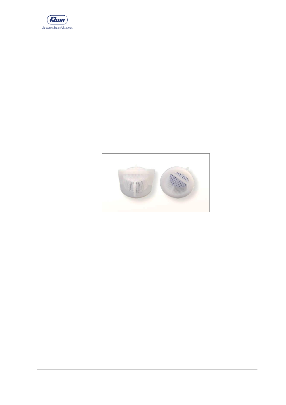
Safety / Maintenance / Repair Works
83
Intervals
Preparation
Procedural Method
8.2.1 Cleaning the Sieve in the Wat er Connec t ion
The sieve in the water connection may become clogged by
particles or minerals in the water supply and the water supply to
the device will be affected.
Depending on the water quality. At the latest when the pressure
vessel is not correctly fille d
Pull out t he mains plug
•
Close off t he water supply to the device
•
1. Remove the hose on the fixed-water supply (Figure 4.4.3-F)
2. Pull out the sieve with pliers
3. Clean the filter under running water
4. Replace the sieve again
5. Correctly reassemble the water connection and inspect it
secure fit and leak tightness.
Figure 8.3.1: Sieve from different views
© Elma Schmidbauer GmbH BA_Elmasteam_8_Vers.07.2016
Page 84
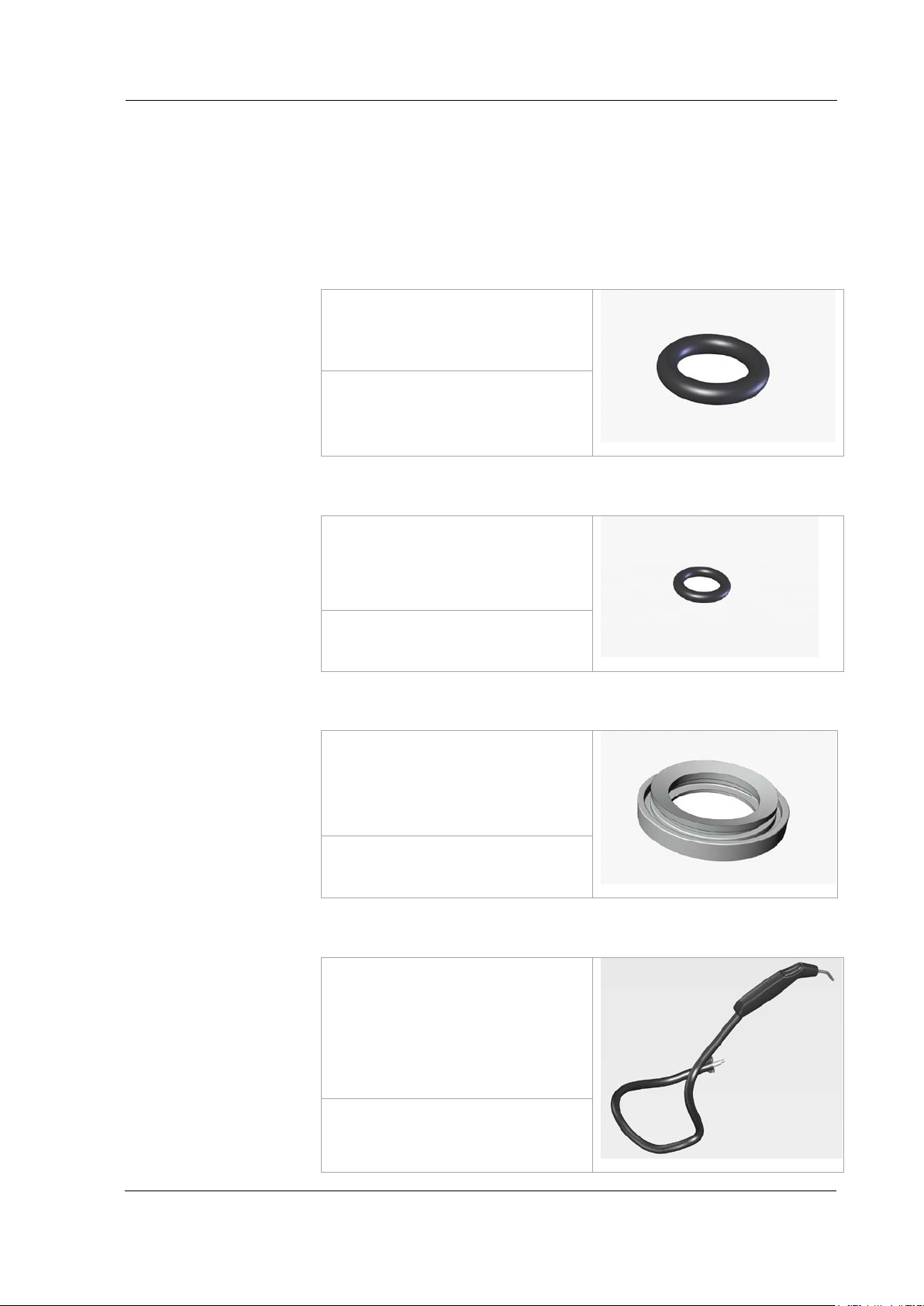
Safety / Maintenance / Repair Works
84
Depending on the function and
107 0074
Depending on function and
105 7949
Depending on visible signs of
105 7953
Depending on visible signs of
106 6873 Hose
Replacement Interval
Item Number
Change interval
Item Number
Replacement Interval
Item Number
Replacement Interval
Item Number
8.3 Wear and Tear Parts
Wear and tear parts are excluded from the warranty.
8.3.1 O-ring in the Pressure Vessel Screw Cap
characteristics of the material.
8.3.2 O-ring Nozzle
occurring leakage (water dripping
from gland).
Observe the service instructions.
8.3.3 Seal on the Collecting Tray
wear (for example, cracks).
Observe the service instructions.
8.3.4 Hose (handpiece)
wear (for example, cracks).
We recommend that the hose is
completely replaced with the
manual unit.
Observe the service instructions.
106 6835 Manual unit with hose
BA_Elmasteam_8_Vers.07.2016 © Elma Schmidbauer GmbH
Page 85
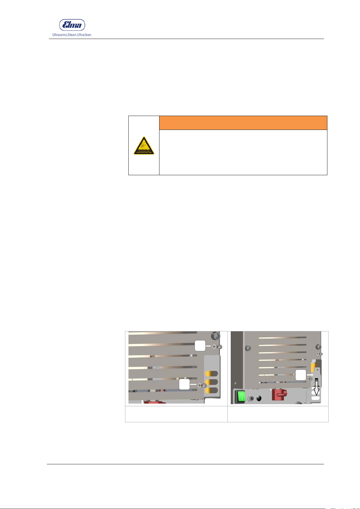
85
• Device damage will be caused by overpressure
Figure 8.4.1.1: Screwing the safety
Figure 8.4.1.2: Removing the
Preparation
Tools required
Procedural Method
A
B
8.4 Safety Valve
8.4.1 Inspect biannually
Inspect the safety valve in biannual intervals to ensure the safety
according to the manufacturer´s provisions.
WARNING
Hot vapours/hot liquids
Severe burns and risk of scalding
• Replace the safety valve when a malfunction is
detected
The device must be depressurised and switched off.
3 mm Allen key (or Torx T20)
Safety / Maintenance / Repair Works
1. Open screws (Figure 8.4.1.1-A).
2. Remove the cover (Fig 8.4.1.2-B) in the direction of arrow
3. Turn the cone (Figure 8.4.1.3-C) by hand anti-clockwise until it
stops.
4. Securely screw the cover (heat protection for the terminals).
5. Switch on the device and let it heat up until steam exits from
the safety valve (audible hissing sound).
6. Switch off the device again and wait until it has cooled down
and is depressurised.
7. Remove the cover (Fig 8.4.1.2-B).
8. Tighten the cone by hand clockwise until it stops.
9. Securely screw the cover (Figure 8.4.1.1-A).
A
valve, opening the cover
© Elma Schmidbauer GmbH BA_Elmasteam_8_Vers.07.2016
safety valve cover
Page 86
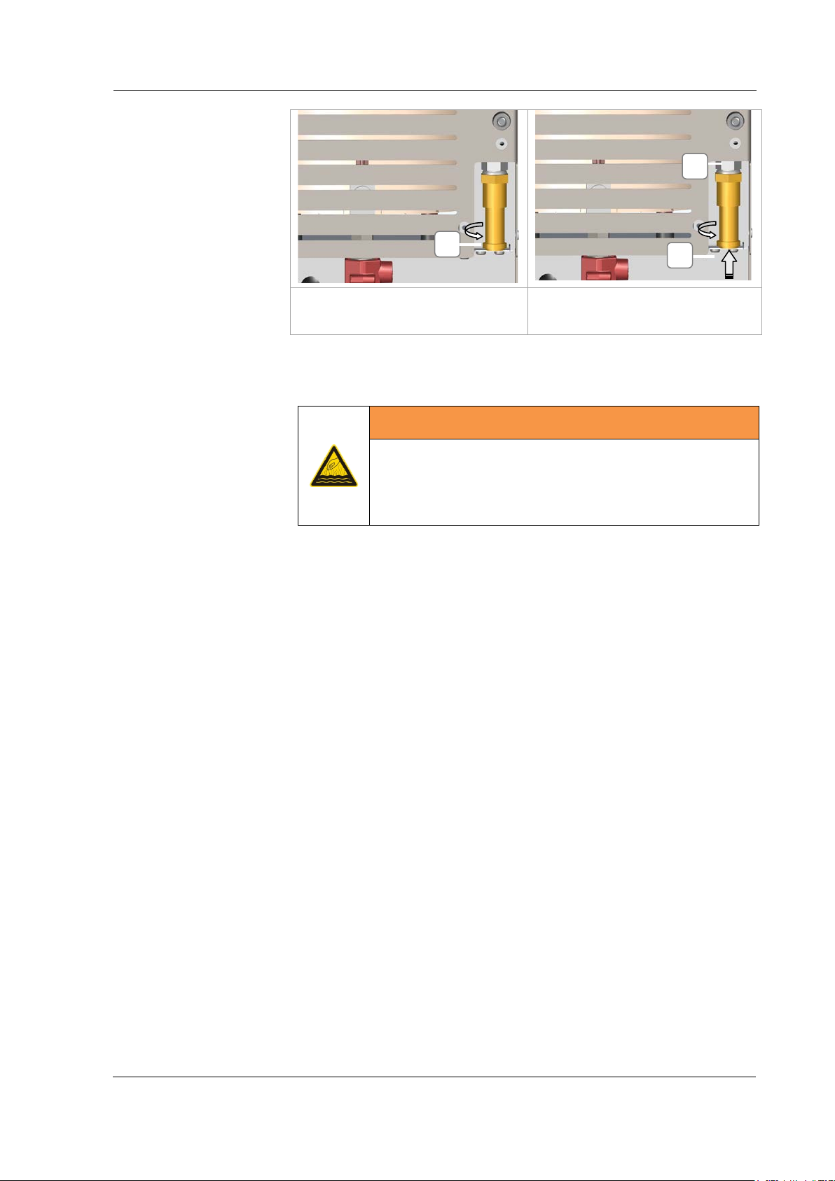
Safety / Maintenance / Repair Works
86
Figure 8.4.1.3: Screwing off the
Figure 8.4.1.4: Renewing the
• Device damage will be caused by overpressure
Preparation
Tools required
Procedural Method
C
D
E
safety valve cone
safety valve (Chapter 7.4.2)
8.4.2 Replacement every 3 years
WARNING
Hot vapours/hot liquids
Severe burns and risk of scalding
• Replace safety valve
The device must be depressurised and switched off.
3 mm Allen key (or Torx T20), socket wrench SW 20,
open-ended spanner 19 mm.
1. Open the screws (Figure 8.4.1.1.A).
2. Remove the cover (Figure 8.4.1.2-B) in the arrow direction.
3. Screw off the safety valve with the socket wrench. Insert the
socket wrench in the safety valve in the direction of arrow and
unscrew it in an anti-clockwise direction (Figure 8.4.1.4-E).
Hold the open-ended spanner against the base (Figure 8.4.1.4D).
4. Screw on a new safety valve with seal (Figure 8.4.1.1).
5. Securely screw on the cover.
6. Switch on the device and let it heat up and then inspect the
screws and glands for leaks (no steam can leak out).
BA_Elmasteam_8_Vers.07.2016 © Elma Schmidbauer GmbH
Page 87
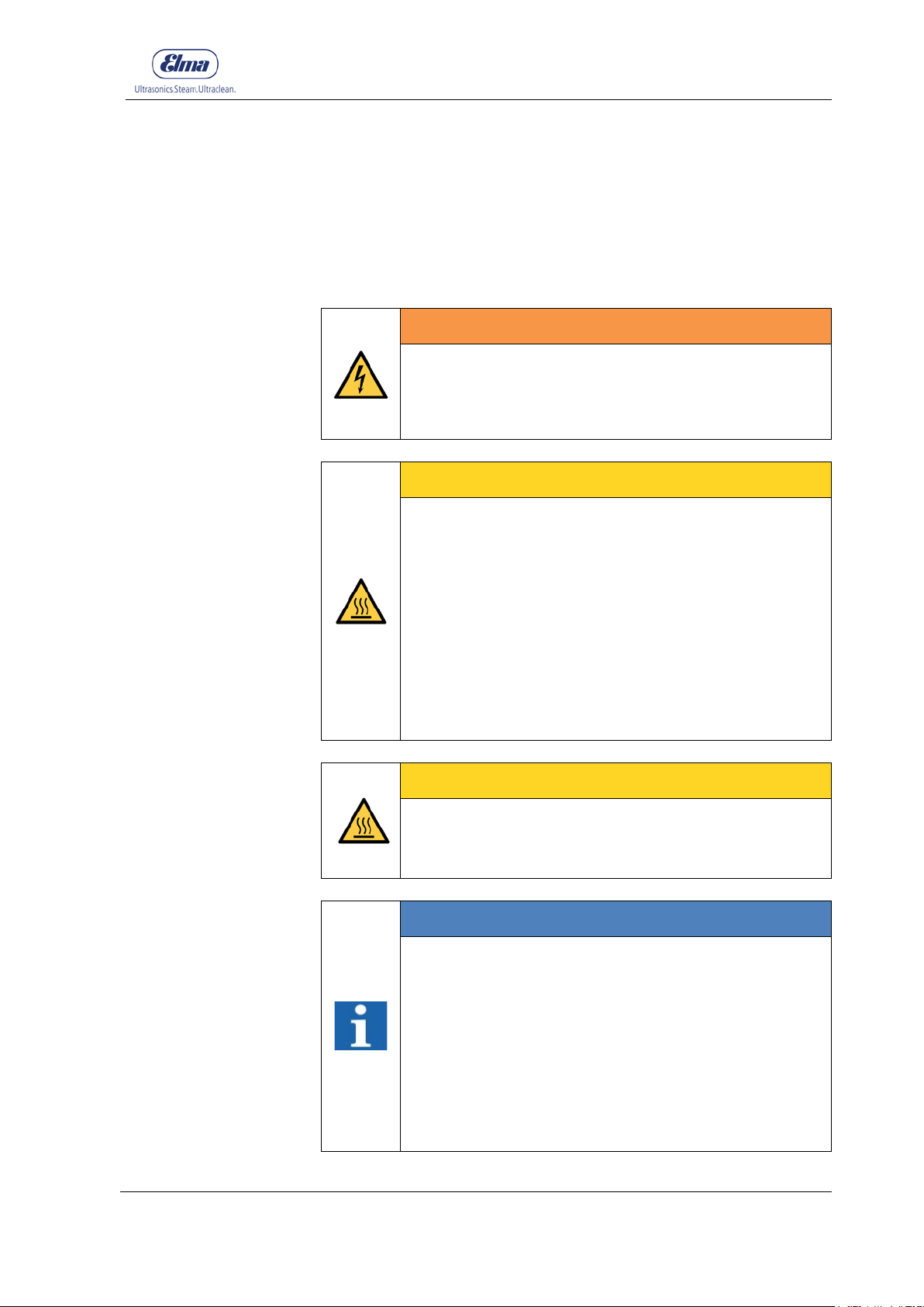
87
repair works.
8.5 Repair Works
Contact the supplier or manufacturer of this device in case of
repair works.
Repairs require expertise and may only be carried out by qualified
personnel.
WARNING
Energised parts in the device!
Electric shocks!
• Unplug the unit from the mains supply before any
CAREFUL
Escaping hot steam!
Scalding!
• Only open the pressure tank screw cap on the filler
neck when the device is depressurised.
• Only dismantle pressure-carrying parts in the
device when the device is depressurised!
• Observe the gauge display (Chapter 3.6.3D)! The
device remains under pressure as long as one
segment is illuminated on the value scale on the
gauge.
• Device can before opening to cool down.
Safety / Maintenance / Repair Works
Hot surfaces!
Burns!
• Device can before opening to cool down.
INFORMATION
Only original parts may be used for repair works.
The CE Conformity Declaration can become invalid in
certain instances by opening the device.
The manufacturer assumes no liability for incurred
damages due to unauthorised opening of the device.
If the device needs to be returned to a service centre
or to the manufacturer, then it must be ensured that
the device has been emptied and is transported in a
secure package.
© Elma Schmidbauer GmbH BA_Elmasteam_8_Vers.07.2016
CAREFUL
Page 88

Safety / Maintenance / Repair Works
88
8.6 Preparing the Device for Shipping
If it is necessary to return the device to a service centre or to the
manufacturer, then the following points must be noted:
• Let the appliance cool down and empty it completely.
• Remove the connected accessory: Connections for canister,
fixed-water connection, foot switch, compressed air, mains
supply cable
• Disinfect the surfaces.
• Pack the unit securely for transport in a suitable container,
when possible in the original box.
BA_Elmasteam_8_Vers.07.2016 © Elma Schmidbauer GmbH
Page 89

Safety / Maintenance / Repair Works
89
Warning flashes
• Filling level in the pressure
• Fill the device (Chapter 6)
• Heating malfunction
• Send the device to the
Steam suddenly exits on
• Safety valve (Figure 3.6.2-B)
• Disconnect the mains plug or
initially after 30 seconds after
8.7 Troubleshooting
Malfunction Possible Cause Remedying
Filling level flashes
Signal tone sounds
Operating pressure was
not achieved
Scale of values on the
gauge flashes (set
operating pressure)
The pressure value
achieved is not displayed
in ascending order on the
scale of values
the housing (rear side of
the device)
vessel is too low
• Pressure vessel screw cap is
not sealed completely
• Steam flows out from pressure
tank screw cap
has triggered
• Disconnect the device from
the mains supply or switch
off on the power switch
• Allow to cool down
• Tightly screw closed the
pressure vessel screw cap.
If steam escapes from the
pressure vessel screw cap
again, then replace the
sealing ring (Sec. 8.3.1)
service centre
switch off the device at the
mains switch
Possible one-off creaking
sound from the device.
Gauge flashes
For devices with pump:
Pump is not pumping
Filling level flashes
Warning flashes
• The 30 second waiting time
was not observed
• Filling level too low
• For devices with compressed
air: inspect whether the
maximum permissible
connection supply pressure
was observed.
• Send the device to the
service centre
• Pumping operation starts
switching on
• Fill the device manually with
at least 2 litres of water
(Chapter 6.2)
© Elma Schmidbauer GmbH BA_Elmasteam_8_Vers.07.2016
Page 90

Safety / Maintenance / Repair Works
90
Malfunction
Possible Cause
Remedying
Operating display does not
Warning flashes
• Foot switch not connected to
• Inspect the plug for the foot
For devices with pump:
Pump operation does not
switch off
• The white hose in the canister
has slipped upwards
• Sieve in the water connection
is clogged
• Seals in the fixed-water supply
are missing
• Seal (black) for the water
connection to the canister is
missing
• Air in water supply
• Unscrew the canister lid.
Adjust the white water hose
and filling level cable with
float switch to the same level
bring (Figure 4.5.5).
Subsequently repeat the
commissioning process for
the pump.
• Remove the sieve and clean
it (Chapter 8.2.1)
• Insert a seal in the fixed-
water connection (Chapter
4.4)
• Insert a seal in the water
connection to the canister.
Seal may remain displaced
on the device, on the
connection to the device
when unscrewing the water
connection (Chapter 4.5.1A).
illuminate
Service flashes
Signal tone sounds
No steam operation is
possible in soft or strong
mode
No steam operation is
possible in soft or strong
mode
Warning illuminates
Heating does not heat up -
scale of values on the
gauge does not flash even
though steam operation
soft or strong is activated
• Malfunction • Send the device to the
service centre
• Descaling was not carried out
(safety shut-down)
the device (steam operation
via fixed nozzle)
• Ambient temperature of the
device is too high
• Descale the device
switch for whether this is
screwed in up to the stop
(Chapter 4.2.1)
• Plug in the foot switch plug
(Chapter 4.2.1)
• Pay attention to the
environmental conditions
specified by the
manufacturer (Chapter 4)
BA_Elmasteam_8_Vers.07.2016 © Elma Schmidbauer GmbH
Page 91

Safety / Maintenance / Repair Works
91
Malfunction Possible Cause Remedying
No compressed air
discharge possible with
actuation
No steam discharge
possible with actuation
Device is ready for
operation
Steam mode soft or strong
is activated
• Steam pressure < 3 bar
• Compressed air is not
connected
• No compressed air supply
ready
• Solenoid valve defective • Send the device to the
• Wait until the device is ready
for operation (operating
pressure)
• Inspect the compressed air
connection
• Inspect the compressed air
supply
service centre
© Elma Schmidbauer GmbH BA_Elmasteam_8_Vers.07.2016
Page 92

Decommissioning and Disposal
92
Technical and design modifications reserved Elma_ch_07.2016
9 Decommissioning and Disposal
This device must not be disposed of with household waste
(municipal rubbish bin).
The device can be returned to the manufacturer for disposal or
must be disposed of in accordance with the local waste regulations
of the local waste management company.
Drain the unit.
Disinfect the surfaces.
10 Manufacturer´s Address / Contact Address
Elma Schmidbauer GmbH
Gottlieb-Daimler-Str. 17, D-78224 Singen
Telephone Head Office +49 (0) 7731 / 882-0
Fax Head Office +49 (0) 7731 / 882-266
www.elma-ultrasonic.com
Technical Support
BA_Elmasteam_8_Vers.07.2016 © Elma Schmidbauer GmbH
 Loading...