

Elma Elmasteam 4.5 Series, Elmasteam 4.5 basic HP, Elmasteam 4.5 basic, Elmasteam 4.5 basic P-HP Operating Manual
Page 1
Operating Manual
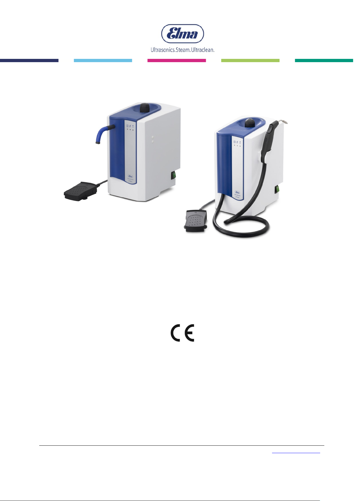
Elmasteam 45 basic basic HP basic P-HP
Steam Jet Cleaner
English
Elma Schmidbauer GmbH Gottlieb-Daimler-Str. 17 D-78224 Singen Tel +49 (0) 7731 / 882-0 Fax +49 (0) 7731 / 882-266 [email protected]
www.elma-ultrasonic.com
document ref. 109 9623
Page 2

Contents
Contents
1 General ............................................................................ 4
2 Important safety instructions ............................................. 4
2.1 Notes for using this manual ........................................ 4
2.2 Description of the warnings on the machine ............... 5
2.3 Important instructions for using the machine .............. 6
3 Product description ........................................................... 9
3.1 Scope of delivery Elmasteam 4
basic P-HP ................................................................. 9
3.2 CE conformity ............................................................ 9
3.3 Functionality ............................................................... 9
3.4 Technical Data ......................................................... 10
3.5 Safety devices .......................................................... 11
3.6 Product description .................................................. 11
5
3.6.1 Elmasteam 4
3.6.2 Elmasteam 4
basic ........................................... 11
5
basic HP | basic P-HP ................. 12
3.7 Description of LED operation indicators ................... 14
3.8 Safety valve ............................................................. 14
5
basic | basic HP |
4 First start-up ................................................................... 15
4.1 Installation and connection conditions ...................... 15
4.2 Fixed nozzle mounting (option) ................................ 16
4.3 Mounting of the wall bracket (option) ........................ 17
4.4 Permanent water connection Elmasteam 4
5
basic P-HP ............................................................... 18
5 Filling the machine.......................................................... 20
5.1 Requirements for water quality ................................. 20
5.2 Manual filling ............................................................ 20
5.3 Automatic filling with pump (basic P-HP) .................. 22
6 Handling in operation ...................................................... 23
6.1 Working with the flexible hand piece ........................ 24
6.2 Working with the fixed nozzle or hand piece ............. 24
7 Safety / Maintenance / Repair ........................................ 25
7.1 Regular visual inspections ........................................ 25
7.2 Rinse pressure tank regularly ................................... 25
7.2.1 For water containing lime ................................... 26
7.2.2 For water containing chloride ............................. 28
7.3 Clean sieve in the water connection (only P-HP) ...... 28
7.4 Wear parts ............................................................... 29
7.4.1 O-ring in the pressure tank screw cap ................ 29
7.4.2 O-ring nozzle ..................................................... 29
7.4.3 Sealing collecting basin ..................................... 29
7.5 Repair ...................................................................... 30
2
BA_Elmasteam_4
5
_EN_Vers.05.2018 © Elma Schmidbauer GmbH
Page 3
3
7.6 Prepare machine for shipment ................................. 30
7.7 Troubleshooting ....................................................... 31
8 Decommissioning and disposal ...................................... 32
9 Manufacturer address/contact address ........................... 32
© Elma Schmidbauer GmbH BA_Elmasteam 45_EN_Vers. 01.2019
Page 4
General
4
Strictly observe the
following before
up
Exclusion of liability
1 General
This operating manual is an integral part of the scope of delivery. It
must be kept easily accessible near the machine and also remain
with the machine in the event of resale.
We reserve the right to make changes from the design shown in
this operating manual due to technical further developments.
An operating manual cannot take into account every conceivable
possibility. For more information or for issues that are not or
insufficiently covered in this manual, please consult your dealer or
the manufacturer.
2 Important safety instructions
Strictly observe the following before start-up!
Read through this manual carefully before use and only use this
electric machine in accordance with the instructions included here.
start-
Also observe any country-specific safety regulations in addition to
the instructions in this manual.
The manufacturer shall not accept any liability in the event of
injuries to persons, damage to the machine or product to be
cleaned which has been caused by improper use contrary to the
instructions in this operating manual.
The owner shall be responsible for training the operating
personnel.
2.1 Notes for using this manual
Read through this manual carefully before use and only use this
electric machine in accordance with the instructions included here.
Symbols in this manual
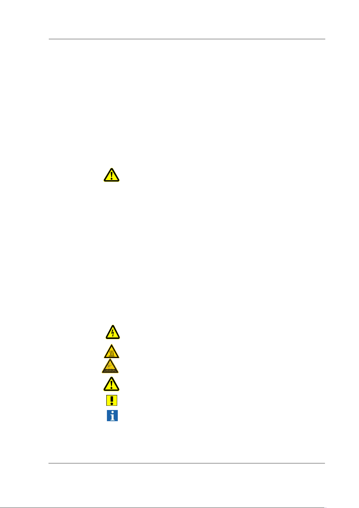
This symbol warns about the risk of injury from electricity.
This symbol warns about the risk of injury from hot surfaces.
This symbol warns about the risk of injury from hot surfaces and
vapours.
This symbol provides a general warning about the risk of injury.
This symbol indicates a risk of property damage.
This symbol indicates supplementary information.
BA_Elmasteam 4
5
_EN_Vers. 01.2019 © Elma Schmidbauer GmbH
Page 5
Important safety instructions
5
Danger
Warning
Caution
Attention
Signal words in this manual
The "danger" signal word warns about the risk of severe injuries
that could be fatal.
The "warning" signal word warns about the risk of severe injuries.
The "caution" signal word warns about the risk of minor to medium
injuries.
The "attention" signal word warns about the risk of property
damage.
2.2 Description of the warnings on the machine
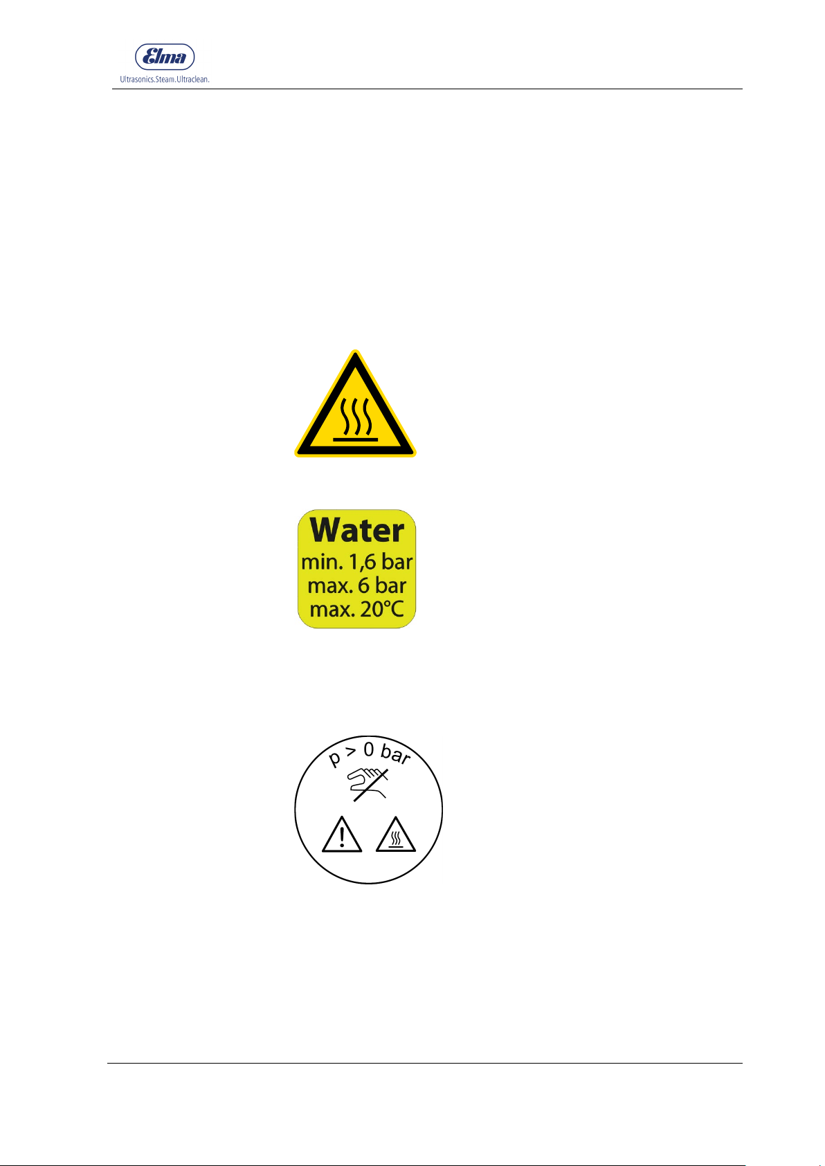
Caution: Hot surfaces/Hot vapours
Notice (only applicable for machines with optional water pump):
For the connection to the water supply system, the minimum water
pressure of 1.6 bar must not be undercut and the maximum water
pressure of 6 bar must not be exceeded. Parts in the machine can
be damaged.
Notice on pressure tank screw cap:
• Do not open at pressure above 0 bar
• Hot surfaces/Hot vapours
• Replace pressure tank screw cap annually (chapter 7.4.1)
• Only fill with water
© Elma Schmidbauer GmbH BA_Elmasteam 45_EN_Vers. 01.2019
Page 6

Important safety instructions
6
Intended use
Operating personnel
Inspection for
possible transport
damage
Installation
Mains power
connection
Prevention of
electrical accidents
Pressure tank filling
No chemical
additives
Danger from hot
surfaces
2.3 Important instructions for using the machine
Use the Elmasteam steam jet cleaner in accordance with the
operating instructions. The manufacturer shall not accept any
responsibility for the safety of persons and the functionality of the
machine in the case of improper use.
This steam jet cleaner is exclusively intended for cleaning objects.
Living beings must never be sprayed with steam!
The machine is only permitted to be used in the industrial sector.
For use as medical product, see additional instructions in chapter
2.4.
Only authorised qualified personnel who are familiar with the
operating instructions are permitted to operate this steam jet
cleaner. Unauthorised persons, particularly children must not
operate this machine.
Check the machine for possible transport damage after unpacking.
Do not start up the machine in the event of recognisable damage.
Contact the carrier and supplier immediately in this case.
Install the machine on a stable, level and dry surface. Protect
against ingress of moisture.
For safety reasons, the machine must only be connected to a
grounded power socket in accordance with the regulations.
The technical details of the rating plate must match the available
connection conditions, particularly mains voltage and connected
load.
For the prevention of electrical accidents and damage to the
machine, the machine must never be sprayed with steam or
exposed to penetrating liquid.
In the event of damage to the machine or entry of moisture, strictly
unplug the mains plug immediately.
The machine is only permitted to be opened by authorised
qualified personnel. The mains plug must always be unplugged
before opening the machine.
Do not put the machine into operation if any mains connection
cable or important parts of the machine such as safety elements or
steam nozzle are damaged.
Connector and coupling must be waterproof if an extension cable
is used. Warning: unsuitable extension cables can be dangerous.
Only operate the Elmasteam steam jet cleaner with sufficiently
filled pressure vessel. Any operation with empty pressure tank can
result in damage to the machine!
The machine must not be operated with chemical additives in the
pressure tank. Only operate the machine with water; see additional
instructions in chapter 5.
Hot temperatures occur during operation, particularly on the rear
panel of the machine and at the steam discharge nozzle.
BA_Elmasteam 4
5
_EN_Vers. 01.2019 © Elma Schmidbauer GmbH
Page 7
Important safety instructions
7
Danger from hot
steam
Electrostatic discharge
Noise emission
Maintenance and
repair
Machines with
permanent water
connection
Upright Transport
Cleaning result
Exclusion of liability
There is a risk of scalding from hot steam in the case of incorrect
operation!
Do not open pressure tank screw cap on the filling tube of the
pressure tank at pressure above 0 bar!
There must not be any unauthorised third persons in the range of
the steam jet. Handle hot steam carefully to avoid injuries.
The pressure tank screw cap must be correctly sealed during
operation.
The outlet of the safety pressure valve is located in the tank cap.
Attention! In the event of any possible tripping of the safety
pressure valve, steam discharges on the underside of the tank
cap.
The outflow of steam at high velocity causes electrostatic charge
generated by friction to accumulate on the nozzle as well as on the
product to be cleaned. The electrostatic charge developed on the
handpiece is continuously dissipated via the ground connection of
the device. Depending on external conditions such as insufficient
conductivity of the floor and/or shoes, dissipation of electrostatic
charge of the product to be cleaned may be impaired.
This absolutely harmless but unpleasant state can be sensed as
“tingling” or “electric shock” (a similar effect may occur, for
example, in carpets or velvet car seats). The discharge that takes
place here can be observed as a visible spark discharge from the
product to be cleaned to the handpiece.
It is recommended in such cases to ground the product to be
cleaned or, if necessary, the wrist of the user (e.g. with an ESD
wrist strap).
Steam jet cleaners can cause unpleasant noise levels during
operation. Use personal hearing protection during the stay in the
work area.
Perform the maintenance work described in this manual (chapter
7) at regular intervals to guarantee the function and safety of the
machine.
Repairs must only be carried out by authorised qualified personnel.
Always unplug the mains plug before servicing or opening the
machine.
Only original parts are permitted to be used for repairs.
Close the water supply of the pump at the water tap after operation
or if the machine is unsupervised.
The machine is only permitted to be stored and transported upright
when the pressure tank is filled; otherwise residues can clog the
steam valve.
The user is responsible for checking the cleaning result.
Elma Schmidbauer GmbH shall not accept any damage and
warranty claims if:
the product is used for any other than the intended purpose
•
specified in the operating manual
unauthorised technical modifications have been made to the
•
product by third parties
© Elma Schmidbauer GmbH BA_Elmasteam 45_EN_Vers. 01.2019
Page 8

Important safety instructions
8
Storage and transport
conditions
the product is not serviced at a service point authorised by the
•
the product is further used despite recognisable safety defects
•
•
the specified maintenance tasks have not been performed.
•
It must be ensured that damage is avoided during storage and
transport of the machine. Storage or transport at temperatures
below freezing point must always be avoided. Freezing water in
the steam jet cleaner can have lasting adverse effects on the
function. The unit before storage or transport empty see cap. 7.2
Temperature during storage: +5 C (+ 41 F) to + 40 C (+ 104 F)
Temperature during transport: -15 C (+ 5 F) to +60 C
(+ 140 C)
Humidity and air pressure during storage and transport:
manufacturer or has not been repaired using original spare
parts
or damage
external forceful impact
10% - 80% relative humidity; non-condensing
Pressure range 500 hPa – 1060 hPa absolute
BA_Elmasteam 4
5
_EN_Vers. 01.2019 © Elma Schmidbauer GmbH
Page 9
Product description
9
Pressure generation
Steam output
Operating medium
3 Product description
3.1 Scope of delivery Elmasteam 45 basic | basic HP | basic P-HP
1 basic machine with 4 litres tank capacity
1 service hose
1 mains cable
1 filling sieve
1 actuation clamp
1 flushing set
3 O-rings for pressure tank screw cap
1 pressure tank screw cap
5
1 water connection hose (Elmasteam 4
5
1 fixed nozzle (Elmasteam 4
1 wall bracket (optional accessory)
1 operating manual
1 information sheet first start-up
1 information sheet water quality and rinsing interval
1 information sheet warranty conditions
basic)
basic P-HP)
3.2 CE conformity
This Elmasteam steam jet cleaner fulfils the CE marking criteria
according to the following EU Directives:
• Low Voltage Directive
• EMC Directive
• RoHS Directive
The declaration of conformity can be requested from the
manufacturer.
3.3 Functionality
Water is heated to approx. 155 °C using a powerful heater in a
manually or automatically filled pressure tank. A relative steam
pressure of approx. 4.5 bar is produced in this way.
The steam is provided via the nozzle.
Tap water with the usual local water hardness or preferably
deionised water. For operation with pump, the conductivity value of
the water must be at least 15 µS/cm (for additional information,
see chapter 5).
© Elma Schmidbauer GmbH BA_Elmasteam 45_EN_Vers. 01.2019
Page 10

Product description
10
Elmasteam 4
5
Elmasteam 4
5
3.4 Technical Data
basic
basic P-HP
basic HP
Mains voltage (V) 220-240 | 115 - 120 220-240
Mains frequency (Hz) 50 / 60 50 / 60
Max. power consumption (W)
220 – 240 V
Max. power consumption (W)
115 – 120 V
2800 2850
1650 -
Rated power at 230 V (W) 2130 2180
Rated power at 115 V (W) 1540
Pressure tank volume (litres) 4 4
Max. filling volume (litres) 3,3 3.3
Operating pressure (bar) 4,5 4.5
Steam temperature at the
output of the nozzle (°C)
Min. water connection pressure
(bar)
≤ 155 ≤ 155
- 1.6
Max. water connection
pressure (bar)
Dimensions with hand piece
W x D x H (mm)
Dimensions with fixed nozzle
W x D x H (mm)
290 x 320 x 420 290 x 320 x 420
250 x 320 x 420 -
- 6
Weight (kg) 6,75 8.05
Case material PC/ABS PC/ABS
BA_Elmasteam 4
5
_EN_Vers. 01.2019 © Elma Schmidbauer GmbH
Page 11
11
A
B C D E F
B D C
E
3.5 Safety devices
Elmasteam steam jet cleaners have all prescribed safety devices
such as
• Safety relief valve
• Overtemperature protection
• Protection of the electrical contacts against spray water
• Contact protection at the ball valve
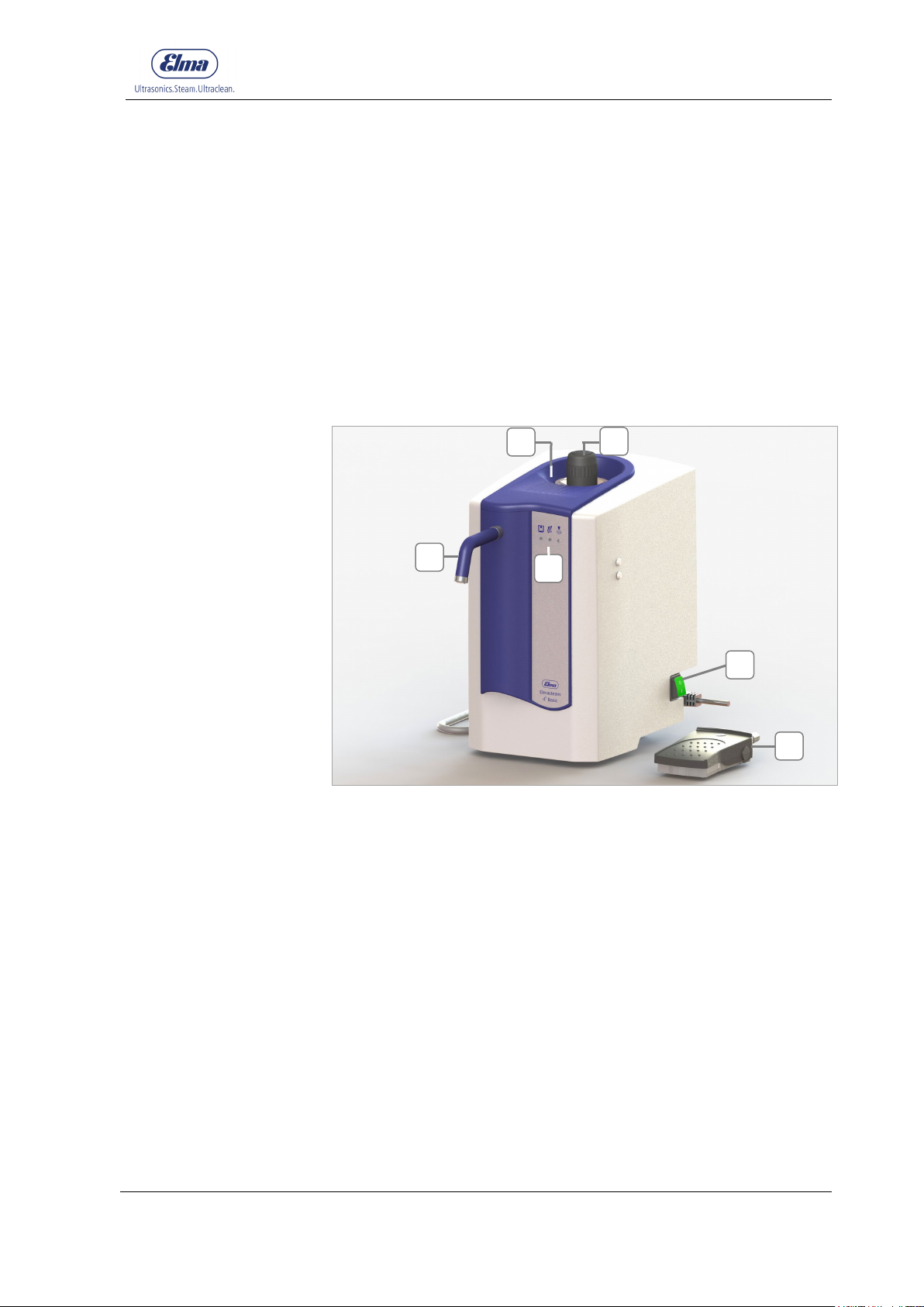
3.6 Product description
Product description
3.6.1 Elmasteam 4
Fig. 3.6.1.1. Elmasteam 45 basic
Collecting basin for overflowing water
Pressure tank screw cap: filling opening for manual filling
5
basic
A
F
Fixed nozzle
Operation indicators
Mains power switch (I) = ON / (0) = OFF
Reset after refilling and signalisation pressure tank empty (chapter
5.2)
Foot switch
© Elma Schmidbauer GmbH BA_Elmasteam 45_EN_Vers. 01.2019
Page 12
Product description
12
G
H
I
A
B
C D E F G
H
G I H
A C B F G D E
H
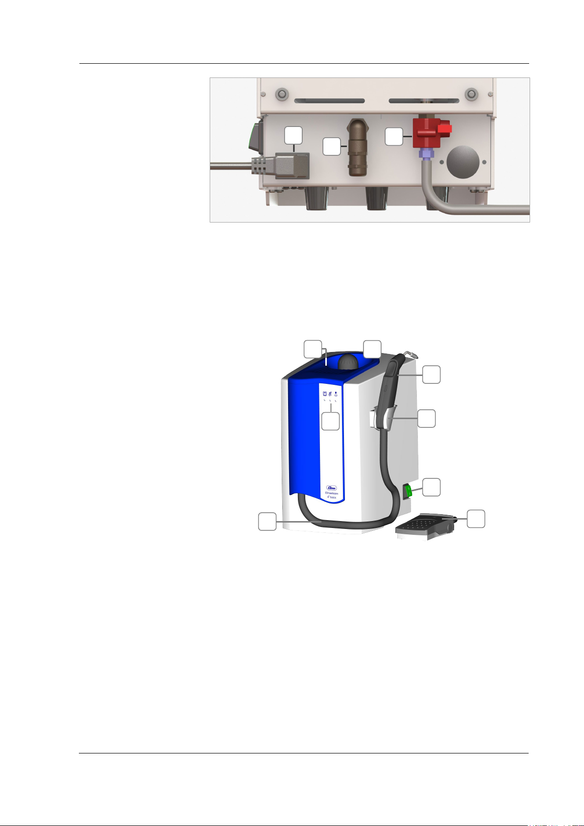
Fig. 3.6.1.2. Elmasteam 45 basic rear side
Device connector with mains cable
Foot switch connector
Ball valve with plastic contact protection and mounted service hose
(chapter 7.2).
3.6.2 Elmasteam 45 basic HP | basic P-HP
Fig. 3.6.2.1. Elmasteam 4
5
basic HP| basic P-HP
Collecting basin for overflowing water
Pressure tank screw cap: filling opening for manual filling
Flexible hand piece
Holder for hand piece
Operation indicators
Mains power switch (I) ON / (0) OFF
Reset after refilling and signalisation pressure tank empty
(chapter 5.2).
Foot switch
Steam hose
BA_Elmasteam 4
5
_EN_Vers. 01.2019 © Elma Schmidbauer GmbH
Page 13
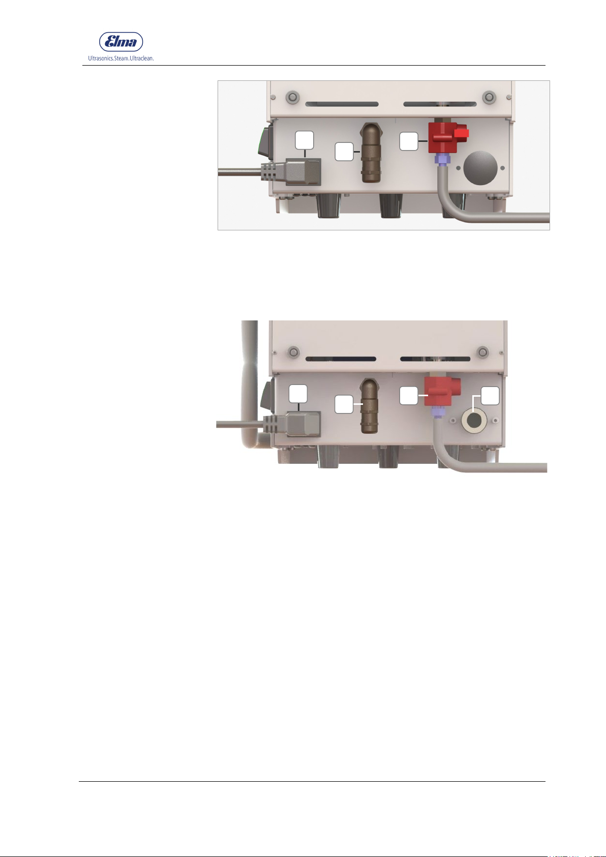
Product description
13
I
J
K
L
I K J K L J I
5
Fig. 3.6.2.2. Elmasteam 4
basic HP rear side
Device connector with mains cable
Foot switch connector
Ball valve with plastic contact protection and mounted service hose
(chapter 7.2).
Fig. 3.6.2.3. Elmasteam 4
5
basic P-HP
Permanent water connection
© Elma Schmidbauer GmbH BA_Elmasteam 45_EN_Vers. 01.2019
Page 14
Product description
14
A
B
C
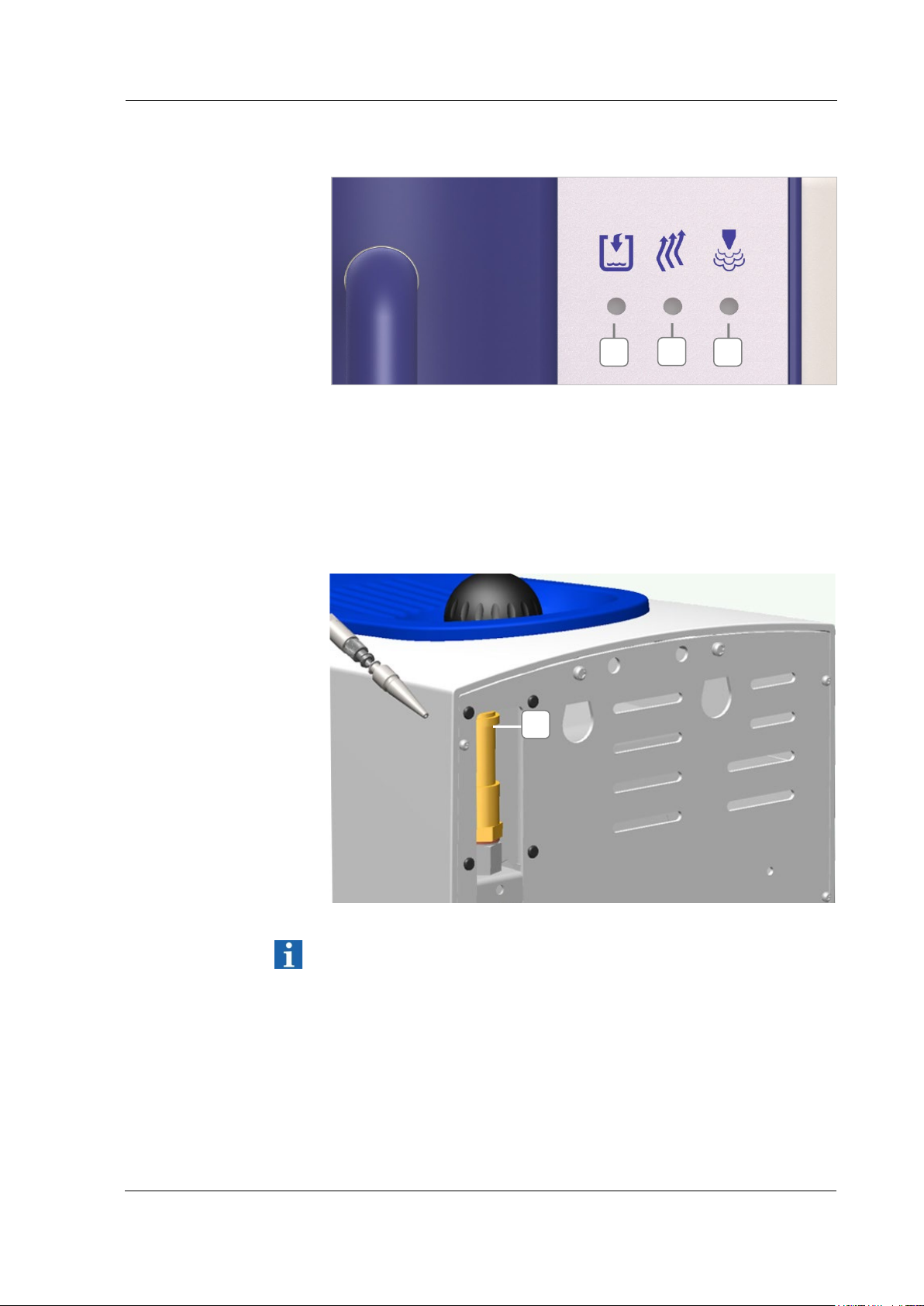
A B C
A
3.7 Description of LED operation indicators
Fig. 3.7.1. View of front side
Pressure tank empty LED indicator (red)
Heater active (heat / reheat) LED indicator (orange)
Operating pressure reached (indicator can extinguish during
operation) LED indicator (green)
3.8 Safety valve
Fig. 3.8.1 safety valve (A)
See chapt. 7.7.
BA_Elmasteam 4
5
_EN_Vers. 01.2019 © Elma Schmidbauer GmbH
Page 15
15
Packaging
Inspection for
transport damage
Installation
conditions
Ambient conditions
Connecting machine
to mains power
supply
4 First start-up
4.1 Installation and connection conditions
Keep the packaging if possible or dispose of it properly in
accordance with the applicable disposal regulations.
You can also return the packaging (at your expense) to the
manufacturer.
Inspect the Elmasteam steam jet cleaner for possible transport
damage before start-up. In the case of recognisable damage, the
machine must not be connected to the mains power supply.
Contact the carrier and supplier immediately.
Install the machine on a stable, level and dry surface.
The air slits on the rear side of the machine must not be covered.
Only the original wall bracket (accessory) is permitted to be used
for wall mounting.
Condensation not permitted.
The machine is only permitted to be operated:
in well ventilated indoor areas
•
up to a height of 2,000 metres above sea level
•
at an ambient temperature of 5 - 40 ºC [41 - 104 ºF] *)
•
at maximum relative humidity of 80% at 31 ºC [87.8 ºF],
•
decreasing linearly to 50% relative humidity at 40 ºC [104 ºF] *)
with mains power supply if the voltage fluctuations are not
•
greater than 10 % of the rated value
*) From 5 - 30 ºC [41 - 86 ºF], the machine can be used with air humidity of up to
80%. At temperatures of 31 - 40 ºC [87.8 - 104 ºF], the air humidity must decrease
proportionally to guarantee the operational readiness (e.g. at 35 ºC [95 ºF] = 65%
air humidity, at 40 ºC [104 ºF] = 50% air humidity). The machine must not be
operated at temperatures above 40 ºC [104 ºF].
First start-up
© Elma Schmidbauer GmbH BA_Elmasteam 45_EN_Vers. 01.2019
Connect the Elmasteam steam jet cleaner to a suitable grounded
power outlet. The technical details of the rating plate must match
the available connection conditions, particularly mains voltage and
connected load.
Page 16
First start-up
16
Procedure
A
B
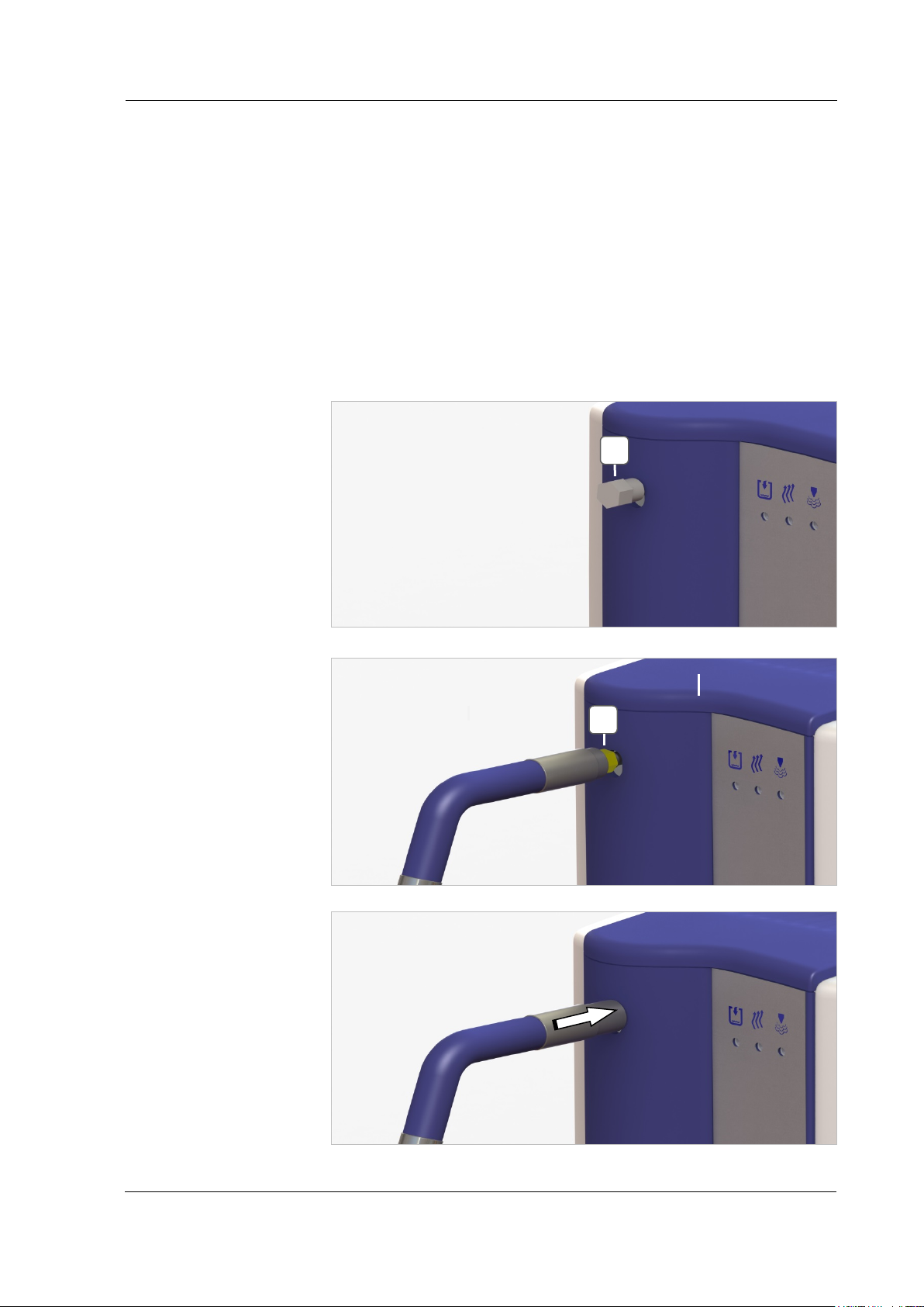
4.2 Fixed nozzle mounting (option)
Ensure that the Elmasteam is switched off and depressurised.
1. Remove the blanking plug by unscrewing the nut (Fig.
4.2.1.A).
2. Screw the fixed nozzle with the nut (Fig. 4.2.2.B) onto the
connection nozzle on the machine.
3. Tighten the nut with a ¼ turn using a 12 mm open-ended
spanner.
4. Slide the black protection sleeve in the direction of the arrow
over the nut (Fig. 4.2.3.).
Fig. 4.2.1 Blanking plug in the delivery condition
Fig. 4.2.2 Screwing on hand piece
Fig. 4.2.3. Sliding protection sleeve over connection
BA_Elmasteam 4
5
_EN_Vers. 01.2019 © Elma Schmidbauer GmbH
Page 17
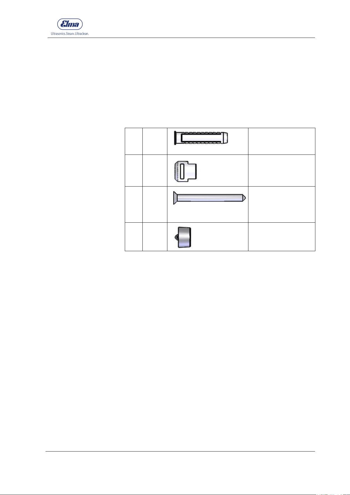
17
(A)
2 Art. No. 1058680
(B)
2
Art. No. 1058678
(C)
2
Art. No. 1066448
(D)
2 Art. No. 1063024
Wall bracket
fastening material
Procedure
4.3 Mounting of the wall bracket (option)
Walls made of concrete, natural stone, dense structure, solid
calcium silicate (lime sand) and solid plasterboard are suitable for
attachment of the wall bracket.
Ensure there is a stable base.
The following parts are supplied for the mounting of the wall
bracket:
Plug
Suspension fitting
Screw
First start-up
Spacer
1. Drill
2 holes Ø 8 mm 90 mm apart and minimum 50 mm depth.
2. Press the plugs (A) as far as they will go into the holes.
3. Put the suspension fittings (B) on the screws (C) and align the
heads of the suspension fittings (B) upwards with the slots.
4. Turn the screws (C) into the plugs until only the suspension
fittings (B) are still visible.
5. Attach the 2 spacers (D) to the rear side of the machine.
6. Attach the machine using the openings on the rear side (E) in
the installed suspension fittings.
© Elma Schmidbauer GmbH BA_Elmasteam 45_EN_Vers. 01.2019
Page 18
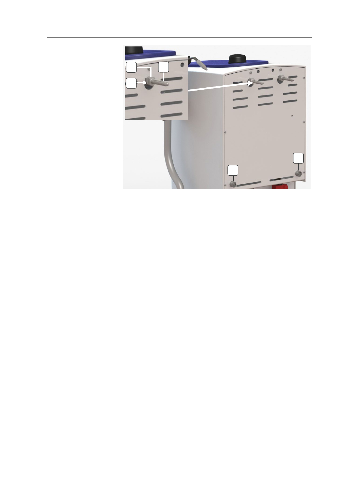
First start-up
18
Exclusion of liability
Mounting procedure
B
A
E
D
D
Fig. 4.3. View with plugs in the mounted state
The manufacturer shall not accept any liability in the event of
injuries to persons or damage to the machine that has been
caused by incorrect mounting or defective quality of the
attachment wall.
4.4 Permanent water connection Elmasteam 45 basic P-HP
Ensure that the Elmasteam steam cleaner is switched off.
The minimum water pressure of 1.6 bar must not be undercut. The
maximum water pressure of 6 bar must not be exceeded.
Components in the machine can be damaged.
Use the supplied water hose. If required, an extension hose (2 m)
can be ordered as optional accessory (106 5691).
1. Put the flat seals included in the delivery
(Fig. 4.4.1.A) into the screw thread (Fig. 4.4.1 B and C).
2. Screw the connector (Fig. 4.4.1.B) of the water hose to the
water hose connection of the Elmasteam (Fig. 4.4.2.D |
4.4.3.F)
3. Connect the water hose to the water line (Fig. 4.4.3.E.).
Pay attention to correct and secure fastening of the water
hose.
BA_Elmasteam 4
5
_EN_Vers. 01.2019 © Elma Schmidbauer GmbH
Page 19
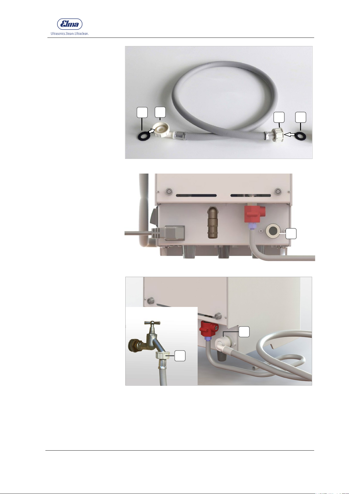
First start-up
19
D A B C A
F
Fig. 4.4.1. Water hose (included in delivery)
Fig. 4.4.2. Machine connection (D) to the water supply (water pipe)
E
Fig. 4.4.3. Connected water hose
© Elma Schmidbauer GmbH BA_Elmasteam 45_EN_Vers. 01.2019
Page 20
Filling the machine
20
Pressure reduction for
"Pressure tank empty"
indicator
Switch off mains power
switch
Let machine cool down
5 Filling the machine
5.1 Requirements for water quality
Basically, the machine is only permitted to be operated with
drinking water or demineralised water*.
*Elmasteam 45 basic P-HP with integrated pump:
If the conductivity of the water <15µS/cm or if the conductivity is
unknown, 1 level teaspoon of table salt must be added to the pressure
tank during initial commissioning (one-time only!). Dissolve the salt in a
glass of water and fill into the filling opening.
The salt does not pass into the steam phase and thus remains in
the machine; therefore the addition is only necessary during initial
commissioning or after decalcification of the machine (see chapter
7.2)
The Elmasteam should preferably be operated using
demineralised water. This can significantly increase the service life
of the machine.
The water quality significantly affects the maintenance intervals
(see chapter 7).
5.2 Manual filling
Start the filling process from point 4 when the machine is
depressurised.
First reduce the pressure when the machine is warmed up.
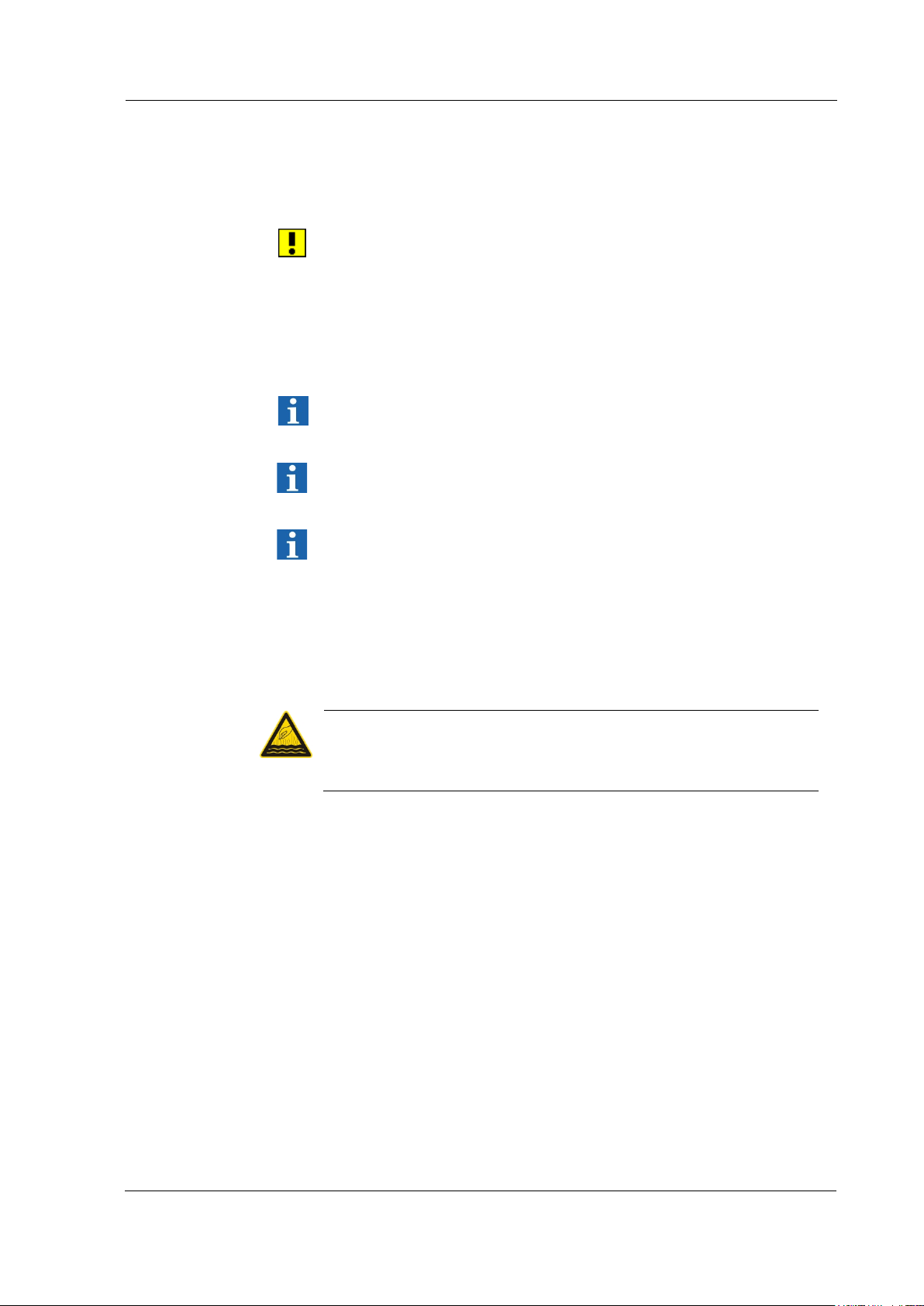
Risk of scalding from discharging steam!
Do not open pressure tank screw cap when the steam pressure
CAUTION
is above 0 bar.
1. Let residual steam pressure escape through the steam nozzle.
1.1. Machine version with hand piece:
1.1.1 Fix the hand piece.
Ensure that the discharging steam does not present any
hazard for persons or equipment.
1.1.2 For draining the residual steam pressure, keep the foot
switch pressed until no more steam escapes (approx. 40 50 seconds).
1.2 Machine version with fixed nozzle:
1.2.1 For draining the residual steam pressure, keep the foot
switch pressed until no more steam escapes (approx. 40 50 seconds).
2. Switch off the machine at the mains power switch (0) (Reset).
3. After complete depressurisation, the machine must still cool
down for approx. 5 minutes to prevent spontaneous steam
formation during filling.
BA_Elmasteam 4
5
_EN_Vers. 01.2019 © Elma Schmidbauer GmbH
Page 21
21
Fill pressure tank
CAUTION
Switch on the mains
power switch
Filling the machine
4. Open pressure tank screw cap slowly (an integrated pressure-
ventilation system lets a stem possibly still in the pressure tank
escape sideways at the pressure tank screw cap during
opening of the screw connection).
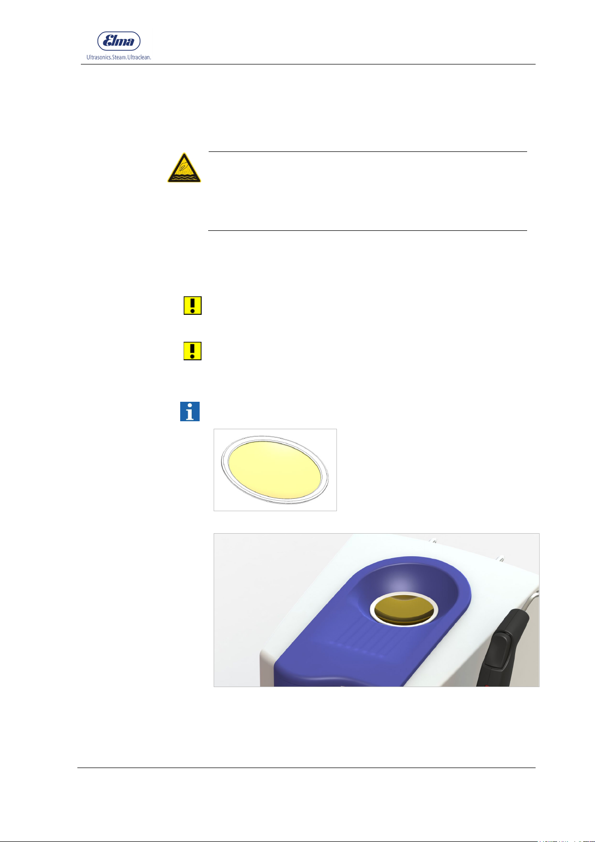
5. Place the sieve in the collecting basin (Fig.5.2.1 | 5.2.2).
Risk of scalding from discharging steam during filling!
Let pressure tank cool down (see point 3)!
Fill pressure tank slowly.
Do not bend over the filling opening of the pressure tank during
filling.
6. Fill water slowly!
Note the maximum filling volume of the pressure tank capacity
of approx. 3.2 litres.
7. Remove the sieve.
Wipe off water that has overflowed. Encrusted residues can impair
the safety mechanism in the pressure tank screw cap.
8. Check the opening of the pressure tank screw cap. In the case
of recognisable clogging, replace the pressure tank screw cap
for safety reasons.
9. Close the pressure tank screw cap by hand (hand tight).
10. Switch on the machine at the mains power switch ( I ).
If the machine has preciously signalled a minimum fill level using
the red LED, this signal is reset by the power off and power on.
Fig. 5.2.1. Sieve for inserting in the collecting basin
Fig. 5.2.2. Sieve inserted in the collecting basin for the filling process
© Elma Schmidbauer GmbH BA_Elmasteam 45_EN_Vers. 01.2019
Page 22
Filling the machine
22
Pump ensures
optimum fill level
ATTENTION
ATTENTION
ATTENTION
5.3 Automatic filling with pump (basic P-HP)
Risk of brackish water backflow into the water supply!
A system separator must be installed between the water
connection on the building side and the Elmasteam to protect
drinking water against non-potable water.
The operating company is responsible for the implementation of
the measure.
The pump fills the pressure tank with the optimum filling amount of
water automatically. No waiting time are produced due to
necessary cooling down phases as for manual filling.
Risk of water damage from possible detachment of the water
hose!
Close the water supply of the pump at the water tap after
operation or if the machine is unsupervised.
Risk of water damage from overfilling of the pressure tank!
Observe requirement for the water quality (see chapter 5.1).
1. Before the first filling, fill the pressure tank manually with
approx. 2 litres of water (see chapter 5.2).
It is expedient for the first filling of the Elmasteam using the
pump to unscrew the pressure tank screw cap to let the air
escape from the system.
2. Open the water tap for the water supply.
Check the hose connections for leaks and tightness.
3. Switch on the machine.
After approx. 10 seconds, the machine starts filling and heating
the pressure tank.
4. Screw the pressure tank screw cap closed again after the
automatic filling.
Further refilling is performed automatically during operation.
Note in the case of incorrectly dimensioned softening cartridges in
the water supply line: When the solenoid valve for the water inlet
closes, a natural rebound on the line occurs as is also produced
when closing a water tap. This can result in damage in the case of
too weakly dimensioned softening cartridges.
BA_Elmasteam 4
5
_EN_Vers. 01.2019 © Elma Schmidbauer GmbH
Page 23
23
Requirements
Pressure tank must
be filled
Switch on machine
Operational
readiness
Holding the workpiece
Suitability of the
product to be
cleaned
Suitability of the
instruments
Distance from the
steam discharge
Cleaning result
6 Handling in operation
Risk of scalding from hot steam!
Act cautiously when steam discharge is activated.
WARNING
WARNING
Avoid hazardous situations caused by unintended activation of
the steam output.
There must not be any unauthorised third persons in the range
of the steam jet during the steam spraying.
Lock the steam button using the red lock on the hand piece.
Use of the actuation clamp for the hand piece is only authorised
for the pressure reduction process when the machine is
switched off!
Danger from hot surfaces!
Hot temperatures occur during operation at the steam
discharge nozzle and on the rear panel of the machine.
Put the machine into operation as described in chapter 4.
Ensure that the pressure tank is filled before starting work.
Otherwise, fill the pressure tank as described in chapter 5.
Switch on the Elmasteam at the mains power switch.
The machine starts to build up pressure.
Depending on the fill level, the operating pressure of 4.5 bar is
reached after approx. 15 - 20 minutes. The green LED indicator
lamp signals the operational readiness.
The green LED indicator lamp can extinguish depending on the
duration of the steam dispensing.
Handling in operation
Steam can continue to be dispensed during the reheating.
Use a suitable aid for the safe holding of smaller workpieces.
Before starting the cleaning, ensure that the workpiece to be
cleaned is suitable for this cleaning process. In particular, the
thermal and mechanical load capacity must be taken into account.
Instruments must be resistant to steam.
Keep the workpiece at least 1 cm away from the nozzle in the
steam zone. Check the cleaning success at short time intervals
(visual inspection) and possible adverse effects on sensitive
surfaces of the product to be cleaned.
The user is responsible for checking the cleaning result.
© Elma Schmidbauer GmbH BA_Elmasteam 45_EN_Vers. 01.2019
Page 24
Handling in operation
24
Water that has entered the hand piece from outside can heat up
Procedure
Actuation using foot
switch
Depress
100%
6.1 Working with the flexible hand piece
Observe the safety instructions in chapter 6.
Risk of scalding from steam or hot water discharging from the
hand piece in the area of the steam button!
CAUTION
strongly or evaporate.
Do not immerse hand piece in water.
1. Remove the hand piece from the hand piece holder.
2. Aim the hand piece into a container or sink for draining possible
accumulations of condensation water. Press the foot switch
briefly until steam discharges.
3. Steam the product to be cleaned.
4. Put the hand piece back into the hand piece holder.
6.2 Working with the fixed nozzle or hand piece
Observe the safety instructions in chapter 6.
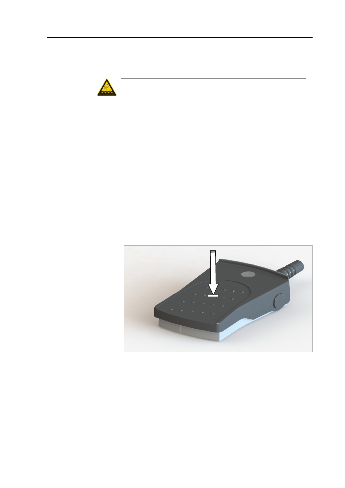
The steam output at the fixed nozzle or the hand piece is activated
with the foot switch.
Activates steam at the fixed nozzle or hand piece.
Fig. 6.2.1. Illustration of foot switch
BA_Elmasteam 4
5
_EN_Vers. 01.2019 © Elma Schmidbauer GmbH
Page 25
Safety / Maintenance / Repair
25
Risk of chemical burns from steam containing acid!
Intervals
CAUTION
7 Safety / Maintenance / Repair
Maintenance work is the obligation of the user. Damage to the
machine that has been caused by not performing maintenance is
not covered by the liability for defects of the manufacturer!
7.1 Regular visual inspections
The following components must be inspected for recognisable
damage at regular intervals:
• the mains power cable
• the foot switch and the electrical supply line to the foot switch
• the steam hose, the hand piece and the steam button
• the pressure tank screw cap: replace in the event of internal
soiling and residues (chapter 7.4.1).
• O-ring of the pressure tank screw cap (chapter 7.4.2)
• also check water hose for correct fastening.
In the event of recognisable damage, the steam jet cleaner must
be taken out of operation for safety reasons. Restarting is only
authorised after repair has been completed.
7.2 Rinse pressure tank regularly
Depending on the local water quality, the maintenance intervals
shown in the tables in chapters 7.2.1 | 7.2.2 are applicable.
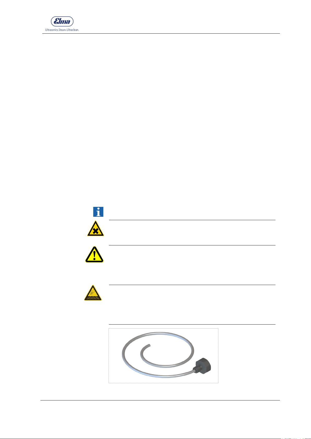
Use the rinsing set (Fig 7.2) included in the delivery.
Never fill decalcifiers or other chemicals in the pressure boiler!
CAUTION
Also only use water for the decalcification process.
Hazard from dangerous excess pressure in the machine!
Lime deposits can result in failure of the safety function of the
safety valve.
The owner is responsible for regular rinsing to descale the
pressure tank.
Risk of scalding from damaged pressure boiler!
Never fill decalcifiers or other chemicals in the pressure boiler!
These can attack and damage the material of the pressure
boiler.
Also only use water for the decalcification process.
Fig.7.2. Rinsing set for connection to the water tap (3/4")
© Elma Schmidbauer GmbH BA_Elmasteam 45_EN_Vers. 01.2019
Page 26
Safety / Maintenance / Repair
26
German
Rinsing
8
6
4
2
1
Intervals
Preparation
Rinsing procedure
7.2.1 For water containing lime
Observe the safety instructions in chapter 7.2.
There is the risk of calcification of diverse machine components for
operation with mains water containing lime (tap water). The
pressure tank must be rinsed by the user in accordance with the
table to avoid lime scale damage to the machine.
In the case of continuous operation with tap water, lime sludge and
scale accumulate in the pressure tank depending on the hardness
of the water. In addition, lime particles detaching from the pressure
tank can clog diverse machine components such as valves and
nozzles. Polished surfaces can be adversely affected (matted) by
such lime particles.
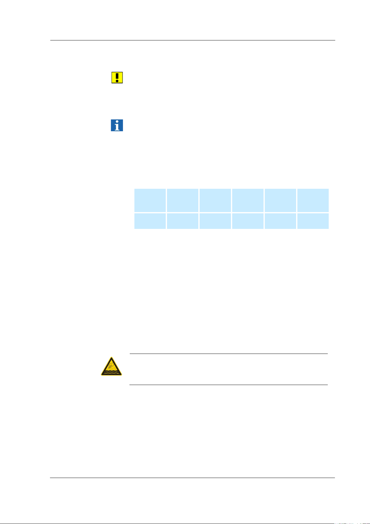
The following cleaning intervals are specified, depending on the
water hardness:
CAUTION
hardness
grade
interval
< 5 °dH
weeks
5 °dH 10 °dH
weeks
10 °dH -
15 °dH
weeks
15 °dH -
20 °dH
weeks
> 20 °dH
week
• Switch off the machine.
• Unplug mains plug.
• Let the machine cool down until it is depressurised (0 bar). After
complete depressurisation, the machine must still cool down for
approx. 5 minutes to prevent spontaneous steam formation
during rinsing.
• Have the maintenance hose included in the delivery ready.
1. Open pressure tank screw cap.
2. Push maintenance hose onto connection nozzle on the ball
valve.
3. Position machine so that the maintenance hose protrudes into
a sink or sufficiently large container and so that the ball valve
can be operated.
Risk of scalding when draining possibly still heated residual
water from the pressure boiler!
Wear gloves for holding the hose.
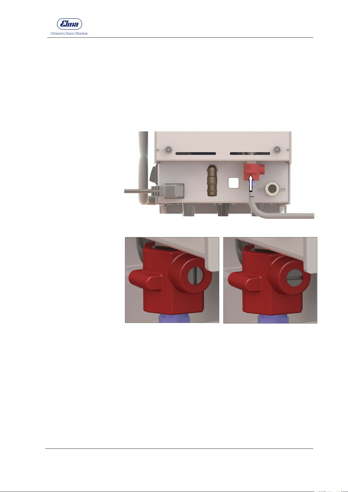
4. Open ball valve using a screwdriver (Fig. 7.2.1.2) and first
drain any still present residual water.
5. Connect rinsing set to a water tap (3/4" connection).
6. Using the hose from the rinsing set, spray the pressure tank in
circular movements.
Continue this process until no more lime residues are rinsed
out of the pressure boiler.
In doing so, the water should be able to flow out of the
pressure tank quickly*.
BA_Elmasteam 4
5
_EN_Vers. 01.2019 © Elma Schmidbauer GmbH
Page 27
Safety / Maintenance / Repair
27
Fig. 7.2.1.2 Ball valve opened
Fig. 7.2.1.3 Ball valve closed
7. Close ball valve (Fig. 7.2.1.3).
8. Remove maintenance hose.
9. For machines that are operated with a pump in combination
with deionised water: Fill 1 level teaspoon of salt into the
pressure tank after the rinsing (see chapter 5.1).
*If no water flows away despite opened ball valve, this is possibly
closed by lime residues:
Remove maintenance hose and clear the opening in the ball valve
using a thin object.
A
Fig. 7.2.1.1 Connect water hose to the ball valve
© Elma Schmidbauer GmbH BA_Elmasteam 45_EN_Vers. 01.2019
Page 28
Safety / Maintenance / Repair
28
Chloride
Rinsing
Intervals
Preparation
Procedure
7.2.2 For water containing chloride
Regular rinsing is also required for water containing chloride.
Otherwise, the chloride concentration in the pressure boiler
continues to increase and the forming hydrochloric acid attacks the
pressure tank.
Procedure as described in chapter 7.2.1 .
content
interval
200 mg/l 150 mg/l 100 mg/l 50 mg/l 0 mg/l
2 weeks 3 weeks 5 weeks 6 weeks 8 weeks
7.3 Clean sieve in the water connection (only P-HP)
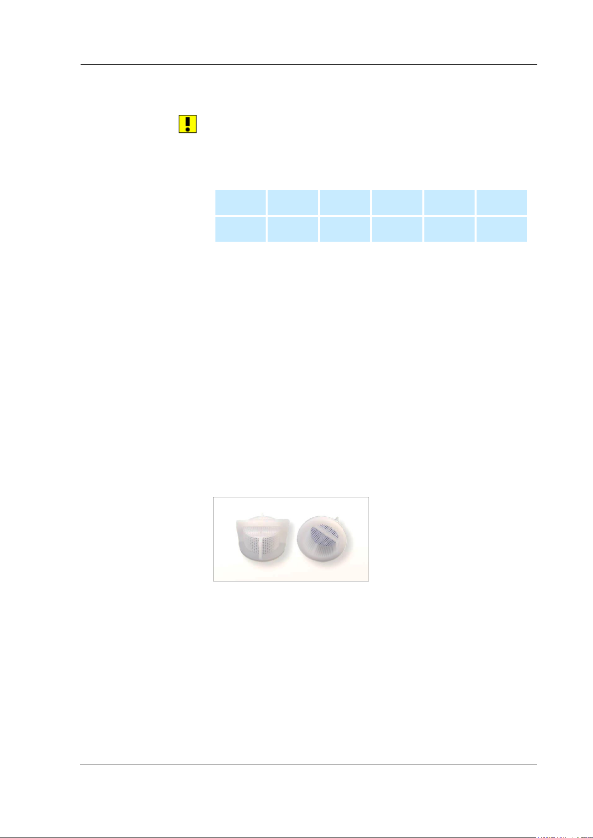
The sieve in the water connection can be clogged by particles and
minerals in the supply system and the water supply to the machine
can be impaired.
Dependent on the water quality. At the latest if the pressure boiler
is no longer filled correctly.
Unplug mains plug
•
Close water supply to the machine
•
1. Remove hose on the permanent water connection (Fig. 4.4.3.F)
2. Pull out sieve using pliers
3. Clean sieve under running water
4. Replace sieve
5. Install water connection again correctly; check for secure
seating and leak tightness.
Fig. 7.2.3. Various views of sieve
BA_Elmasteam 4
5
_EN_Vers. 01.2019 © Elma Schmidbauer GmbH
Page 29
Safety / Maintenance / Repair
29
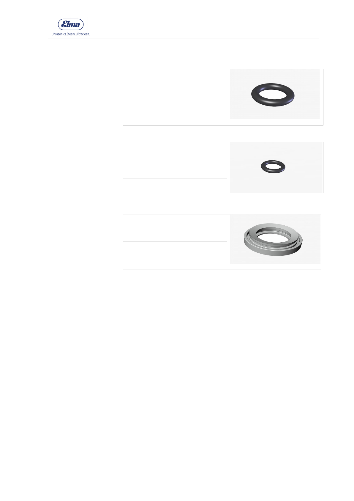
Dependent on the occurrence of
107 0074
Dependent on the function and
105 7949
Dependent on visible wear ( e.g.
105 7953
Replacement interval
Article number
Replacement interval
Article number
Article number
Replacement interval
7.4 Wear parts
7.4.1 O-ring in the pressure tank screw cap
leaks and condition of the
material.
7.4.2 O-ring nozzle
occurrence of leaks (water drips
from the screw cap).
Observe service instructions.
7.4.3 Sealing collecting basin
cracks).
Observe service instructions.
Wear parts are excluded from the warranty.
© Elma Schmidbauer GmbH BA_Elmasteam 45_EN_Vers. 01.2019
Page 30
Safety / Maintenance / Repair
30
7.5 Repair
Contact the supplier or manufacturer of this machine for repairs.
Repairs require specialist knowledge and are only permitted to be
performed by specialist personnel.
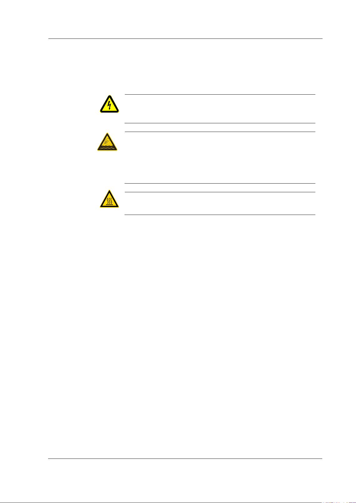
Danger of electric shock from live parts in the machine!
Disconnect the machine from the mains power supply before
WARNING
CAUTION
CAUTION
repair work.
Risk of scalding from discharging steam!
Do not open pressure tank screw cap on the filling nozzle of the
pressure tank at pressure above 0 bar.
Do not remove parts in the machine that are pressurised above
0 bar.
Let the machine cool down before opening.
Danger of burns from hot surfaces!
Let the machine cool down first before opening.
Only original parts are permitted to be used for repairs.
Under certain circumstances, opening the machine can invalidate
the CE conformity.
The manufacturer shall not accept any liability for consequential
damage caused by unauthorised opening of the machine.
7.6 Prepare machine for shipment
The following points must be observed if it is required to send the
machine to a service point or the manufacturer:
• Empty the machine completely before shipping.
• Pack the machine securely for transport in a suitable container,
if possible in the original carton.
BA_Elmasteam 4
5
_EN_Vers. 01.2019 © Elma Schmidbauer GmbH
Page 31

Safety / Maintenance / Repair
31
Pressure does not
• Pressure tank screw cap is not
• Close pressure tank screw
Steam suddenly
discharges with short, loud
• Safety valve has tripped
• Take machine out of
• Water pressure too low
• ensure higher water pressure
7.7 Troubleshooting
Fault Possible cause Remedy
increase to 4.5 bar
LED heating lights
The Tank empty LED
lights even if the tank is
full
• Heater already damaged by
noise development at the
safety valve
For basic P-HP machines
(with pump):
closed leak-tight.
• Heater fault • Send machine to a service
• Heavy scale on heater or
thermostat
overheating due to heavy lime
deposits
• Water supply not opened • Check water supply of the
cap tightly.
If necessary replace sealing
ring
point
• Rinse pressure boiler
(chapter 7.2)
• Send machine to a service
point
operation immediately.
• Send machine to a service
point
machine
Pump no longer delivers
water
• Machine has been switched
on with empty pressure tank;
thereby the maximum pump
time of 2 minutes has been
exceeded;
pump goes into a fault state
and is switched off
automatically
• Sieve in the water connection
is clogged.
• Perform initial filling with
approx. 2 litres of water
• Switch mains power switch
off and then on again (reset)
• Clean sieve (chapter 7.3).
© Elma Schmidbauer GmbH BA_Elmasteam 45_EN_Vers. 01.2019
Page 32

Decommissioning and disposal
32
We reserve the right to make technical and visual modifications Elma_ch_05.2015
8 Decommissioning and disposal
This machine must not be disposed of in domestic waste
(municipal waste bin).
The machine can be sent back to the manufacturer for disposal or
delivered to the local waste disposal in accordance with the local
waste regulations.
Empty the machine.
Disinfect the surfaces.
9 Manufacturer address/contact address
Elma Schmidbauer GmbH
Gottlieb-Daimler-Str. 17, D-78224 Singen
Tel (head office) +49 (0) 7731 / 882-0
Fax (head office) +49 (0) 7731 / 882-266
www.elma-ultrasonic.com
Technical Support
BA_Elmasteam 4
5
_EN_Vers. 01.2019 © Elma Schmidbauer GmbH
 Loading...