

Elko SOU-3 User Manual
1 / 2
SOU-3
cos φ ≥ 0.95
M M
HAL.230V
K
M M
AC12
250V / 7.5A
DC14
24V / 1.5A
AC1
250V / 12A
AC13
250V / 4.5A
AC2
250V / 3.7A
AC14
250V / 4.5A
AC3
250V / 2.2A
AC15
250V / 4.5A
AC5b
1120W
DC5
24V / 3A
AC6a
x
DC12
24V / 12A
AC7b
250V / 2.2A
DC13
24V / 1.5A
02-69/2016 Rev.: 2
J1
J2 J3
SOU-3
SOU-3
0
1
2
10
100
1.000
1.000
10.000
100.000
L
15
18
L
N
1
2
3
4
5
6
7
4
L
N
L
N
L
15
18
L
N
L
N
L
15
18
Made in Czech Republic
ELKO EP, s.r.o.
Palackého 493
769 01 Holešov, Všetuly
Czech Republic
Tel.: +420 573 514 211
e-mail: elko@elkoep.com
www.elkoep.com
Twilight and light switch
• serves as control of the device on the basis of ambient light intensity.
• external version in IP65, box for mounting on the wall
• exact built-in light sensor
• two devices in one, function setup by jumper:
- twilight switch - ramps down during decreasing ambient light intensity, ramps
up during increasing. Used for switching the lights during twilight and in the
night (street illumination and garden lights, illumination of advertisements,
shop windows, etc..)
-light switch - ramps down during increasement of ambient light intensity,
ramps up during decreasement. Used for switching the lights after reaching
the ambient light seting e.g. shinning of sun (blinding - shutters and Venetian
blinds, solar panels - activation...)
• adjustable (by jumper) ranges of light level
• 3 adjustable levels of time delay (for elimination of sh ort-term uc tuations of light
intensity, for example car re ectors lighting)
• supply voltage 230 V AC
• potentialless NO contact 12 A / AC1 switching
Note:
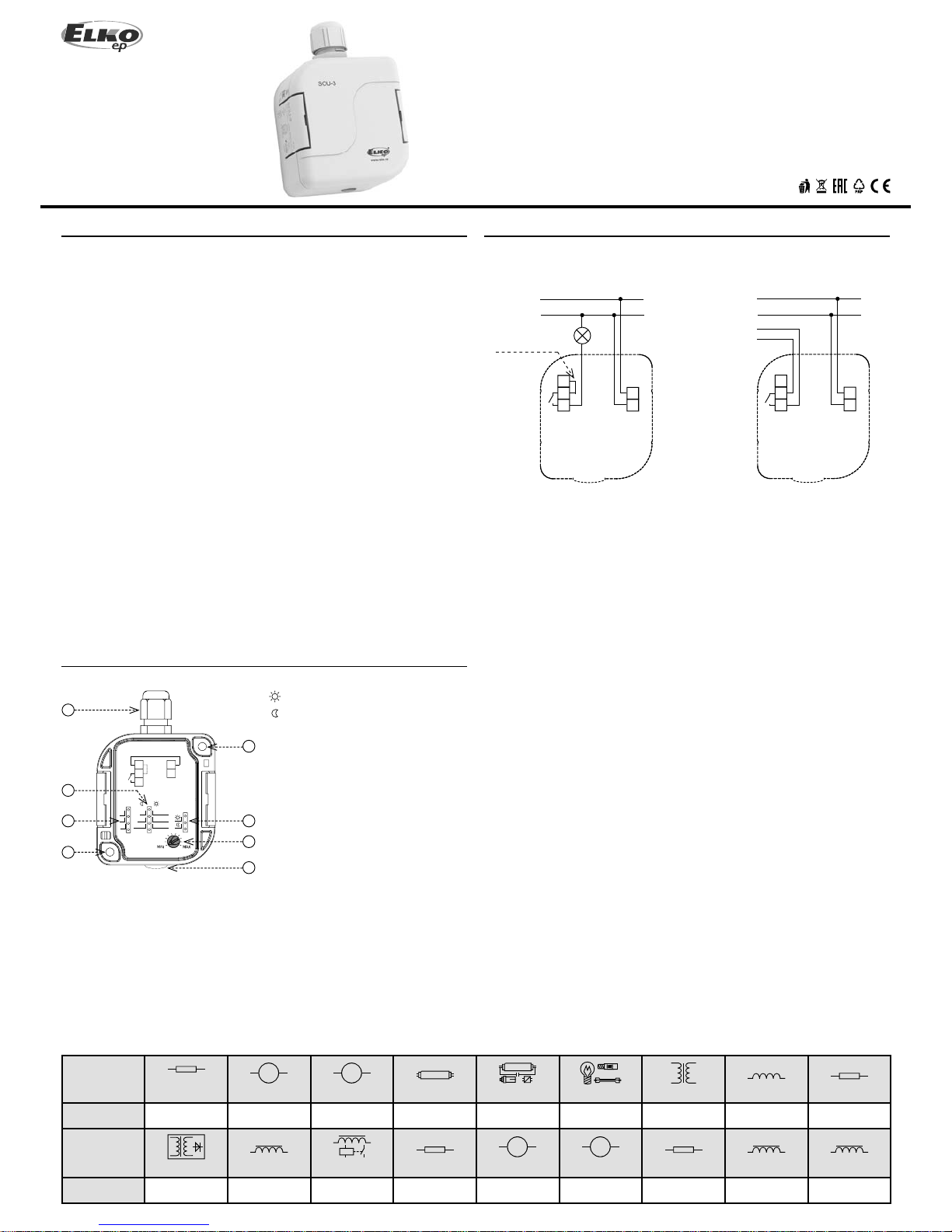
Device is supplied with jumper L-15 (3-wire connection).
For the correct function of device is neccesar y sensor-side down device mounting.
Attach the device w ith a suitable bonding material bas ed to the substrate (eg round
head screw, Ø 4 mm, min. Length 30 mm).
Characteristics
Description
Connection
Type of load
Mat. contacts AgSnO
2
,
contact 12A
Type of load
Mat. contacts AgSnO2,
contact 12A
AC5a
uncompensated
230V / 2.2A (510VA)
DC1
24V / 12A
AC5a
compensated
230V / 2.2A (510VA)
to max. input C=14uF
DC3
24V / 4.5A
EN
- Light switch
- Twilight switch
1. Cable gommet M16x1.5 for cable max.
Ø 10 mm
2. Adjustable range setting (Lx)
3. Delay (min)
4. Hole for mounting on the wall Ø 4.3 mm
5. Function setting
6. Slight setup nish in the frame of range
7. Sensor of ambient light
3-wire connection 4-wire connection
jumper for
L potential
potentialless
NO contacts
2 / 2
SOU-3
15 - 18
15 - 18
t
t
t
tt
L - N
Warning
Technical parameters
The device is constructed to be connected into 1-phase main and must be installed in
accordance with regulations and norms applicable in a particular country. Installation,
connection and setting can be done only by a person with an adequate electro-technical
quali cation which has read and understood this instruction manual and product
functions. The device contains protections against over-voltage peaks and disturbing
elements in the supply main. Too ensure correct function of these protection elements
it is necessary to front-end other protective elements of higher degree (A, B, C) and
screening of disturbances of switched devices (contactors, motors, inductive load etc.) as
it is stated in a standard. Before you start with installation, make sure that the device is
not energized and that the main switch is OFF. Do not install the device to the sources of
excessive electromagnetic disturbances. By correct installation, ensure good air circulation
so the maximal allowed operational temperature is not exceeded in case of permanent
operation and higher ambient temperature. While installing the device use screwdriver
width approx. 2 mm. Keep in mind that this device is fully electronic while installing.
Correct function of the device is also depended on transportation, storing and handling.
In case you notice any signs of damage, deformation, malfunction or missing piece, do
not install this device and claim it at the seller. After operational life treat the product as
electronic waste.
Function
Supply
Supply terminals:
Supply voltage:
Tolerance of supply voltage:
Input (apparent / loss):
Setting the scale level of lighting
Funct ion twilig ht switch
- range 1:
- range 2:
- range 3:
Function light switch
- range 1:
- range 2:
- range 3:
Setting function
Level of light-slight:
Slight set ting
of light level:
Time delay t :
Delay set ting t:
Output
Output contact:
Rated current:
Switching output:
Peak current:
Switched vo ltage:
Mechanical life:
Electrical life:
Other information
Operation temperature:
Storing temperature:
Electrical strengh:
Operation position:
Protection degree:
Overvoltage cathegory:
Pollution l evel:
Max. cab le size (mm
2
):
Suggested power-supply cable:
Dimensions:
Weight :
Standard s:
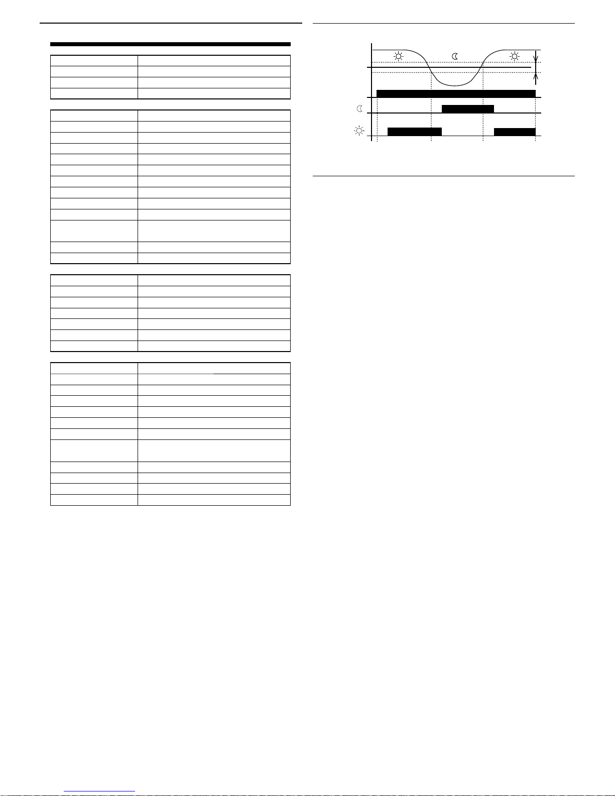
actual
illumination level
setup
illumination level
solid
hysteresis
12%
L - N
AC 230 V / 50 .. 60 Hz
- 15% .. +10%
max. 6 VA / 0.7 W
by jumper J2
1 ... 10 Lx
10 .. . 100 L x
100 ... 1.000 L x
100 ... 1.000 L x
1.000 ... 10.000 Lx
10.000 ... 100.000 Lx
by jumper J3
0.1 ... 1 x range
potenciometer
0 / 1 min. / 2 min.
by jumper J1
1x NO - SPST (AgSnO
2
)
12 A / AC1
3000 VA / AC1, 384 W / DC
30 A / < 3 s
250 V AC / 24 V DC
3 x 10
7
0.7 x 10
5
-30 °C to +60 °C (-22 °F to 140 °F)
-30 °C to +70 °C (-22 °F to 158 °F)
4 kV (supply- output)
sensor-side down or on the side s
IP65
III.
2
max. 1x 2.5, max. 2x 1.5 /
with sleeve ma x. 1x 2.5 (AWG 12)
CYKY 3x 2.5 (CYKY 4x1.5)
96 x 62 x 34 mm (3.8˝ x 2.4˝ x 1.3˝)
122 g ( 4.3 oz.)
EN 60255-6, 61010-1
 Loading...