

Elko RF Touch-B, RF Touch-W User Manual
WIRELESS TOUCH
CONTROL UNIT
USER'S MANUAL
RF Touch user manual
We want to thank you for your purchase of the RF Touch control unit, which is an element of
wireless RF Control system.
RF Touch allows:
you to control many devices trough touch screen
- heating control
- dimming lights
- switching of electrical appliances and equipment
- blinds
- a combination of detectors
- function timers
- Group control of electrical equipment
everything with clear visualization
wireless communication without the need for cabling
2
E
N
RF Touch user manual
Before you start
The instruction manual is intended for installation and use of the equipment. Instructions are always included in the product packaging.
Installation and connection can only make personnel with appropriate qualifications, in compliance with all applicable laws, who are
perfectly familiar with this instructions and functions. Trouble free function is also dependent on transportation, storage and handling.
In case of any signs of damage, deformation, malfunction or missing parts, do not install this product and return it to the seller.
Product and its parts must be at the end of its lifetime handled as electronic waste. Before installation, make sure that all wires, connected
parts or terminals are not live. During the installation and maintenance is necessary to follow safety regulations, standards, guidelines
and special provisions for working with electrical equipment.
Contents:
Before you start .......................
Overview of wireless devices ...
Characteristics of RF Touch .....
Technical speci cations ...........
Installation of RF-Touch W .......
RF Touch Installation-B ............
Description of Control icons ....
Basic Steps ...............................
Settings
- Default setting .........................
- Menu(creating and naming) ...
- Programming ...........................
- Assign a new receivers .......
- Assigned receiver ...............
- Detectors ............................
- Quick Control .....................
- Display .....................................
- Other ........................................
Control
- Temperature regulation ..........
- Switching .................................
- Dimming ..................................
- Blinds .......................................
- Detectors .................................
- Quick control............................
What to do if ............................
Installation Form .....................
3
4
7
8
9
10
11
12
13
14
16
17
18
21
23
24
24
26
30
33
36
38
39
40
42
3
JA-80P
JA-81M
JA-82M
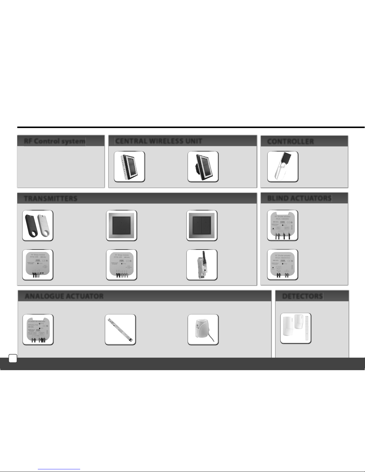
Overview of wireless RF Control devices
RFWB-20/G
2-channel wireless
switch in the design
LOGUS
90
RFWB-40/G
4-channel Wireless
switch in the design
LOGUS
90
RFJA-12B/230V
blind actuator
2 x 8A switching
relay protection
230V AC
RFJA-12B/24V DC
blind actuator
contactless switching
12-24V DC
RFDAC-71B
actuator with analog
output 0 (1) - 10 V
1 x switch contact 16 A
7 functions, 230V AC
Thermo-control
of heating valves
supplied on request
with the product RFDAC-71B
Dimmable ballast
for dimming of uorescent
lamps
supplied on request
with the product RFDAC-71B
RF KEY
4-channel remote
controller - key pendant
RFIM-20B
universal transmitter module
under the switch or button
wall box installation
RFIM-40B
universal transmitter module
under the switch or button
wall box installation
RFSG-1M
Transmitting module
1-module
230 V AC
RF Touch-W
for surface mounting
100 - 230V AC or
adapter (external)
12 V DC
RF Touch-B
for mounting
in the installation
box
100 - 230V AC
All actuators of the RF Control
System can be controlled by
wireless central unit and all
transmitters of the system
simultaneously.
DETECTORSANALOGUE ACTUATOR
RF Control system CENTRAL WIRELESS UNIT
TRANSMITTERS
BLIND ACTUATORS
RF Pilot
remote controller,
colours: white,
anthracite
CONTROLLER
4
E
N
Overview of wireless RF Control devices
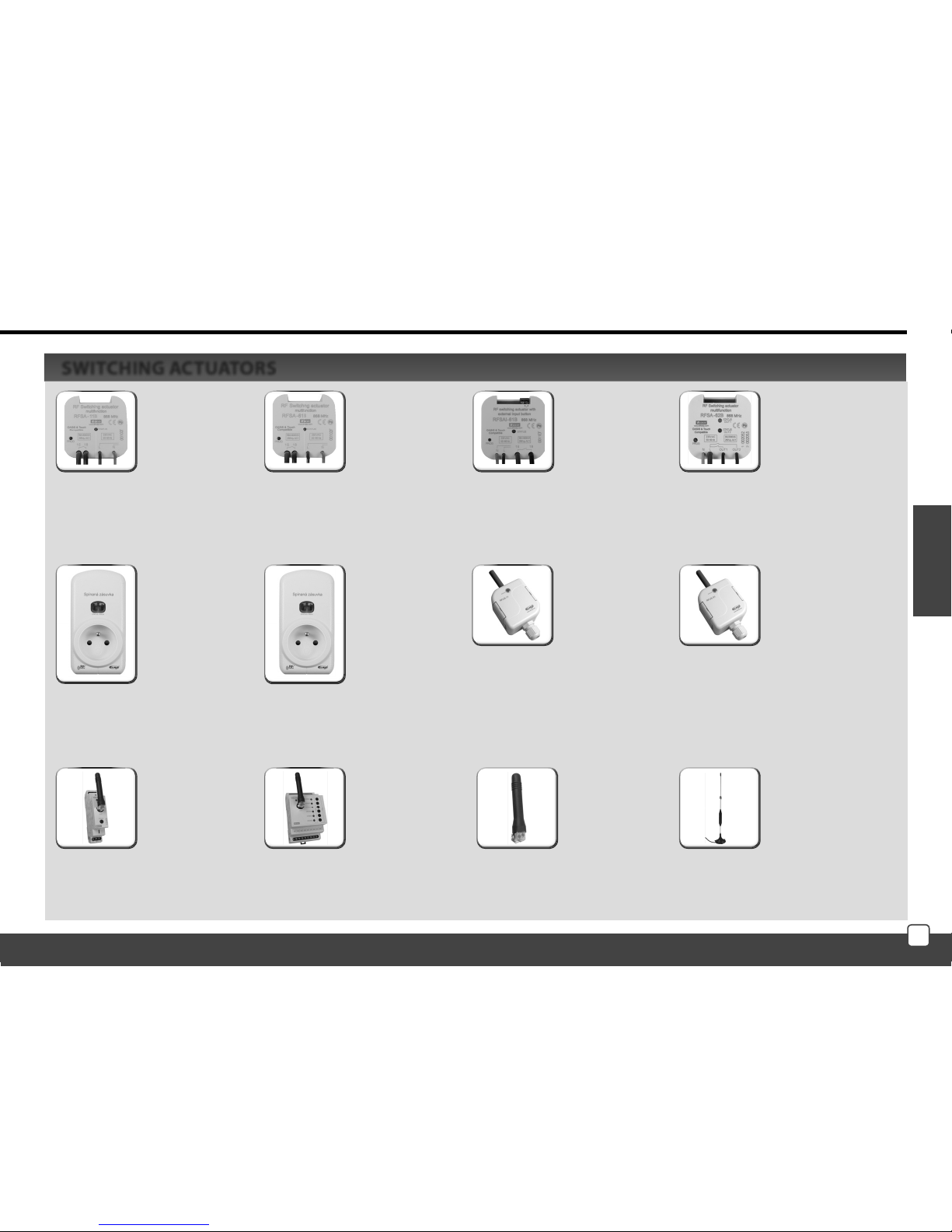
RFSA-11B
single channel
single function
switching actuator
1 x switching
contact 16 A
230V AC
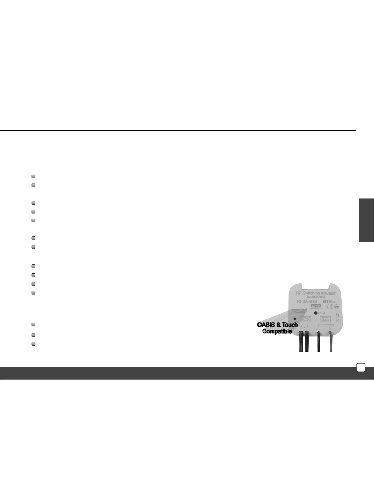
RFSA-61B
single channel
multifunction
switching actuator
1 x switching
contact 16A
230V AC
RFSAI-61B
single-channel
multi-function
switching actuator
with option of
connecting an
external wired
controller
RFSA-62B
2 channel
multifunction
switching actuator
2 x 8A switching
contact
6 functions
230V AC
RFUS-11
single-channel
single-function
switching actuator
1 x switching 16A
230V AC,
protection IP65
RFUS-61
single-channel
multi-function
switching actuator
1 x switching 16A
230V AC,
protection IP65
RFSA-61M
single channel
Multifunction
switching actuator
1x changeover
contact 16 A
6 functions
230V AC
RFSC-11
RFSC-11 singlechannel, singlefunction switched
socket
1 x switching 16A
230V AC
RFSA-66M
six-channel
Multifunction
switching actuator
3 x 8 AND NO
3 x changeover
contact 8A
6 functions 230V AC
RFSC-61
single-channel,
multifunction
switched socket
6 functions
1 x switching 16A
230V AC
Angle antenna
for plastic
switchboards
supplied as standard
for RFSA-61M,
FSA-66M, RFSG-1M
Angle Antenna
for metal
switchboard
can be ordered for
RFSA-61M,
RFSA-66M, RFSG-1M
SWITCHING ACTUATORS
5
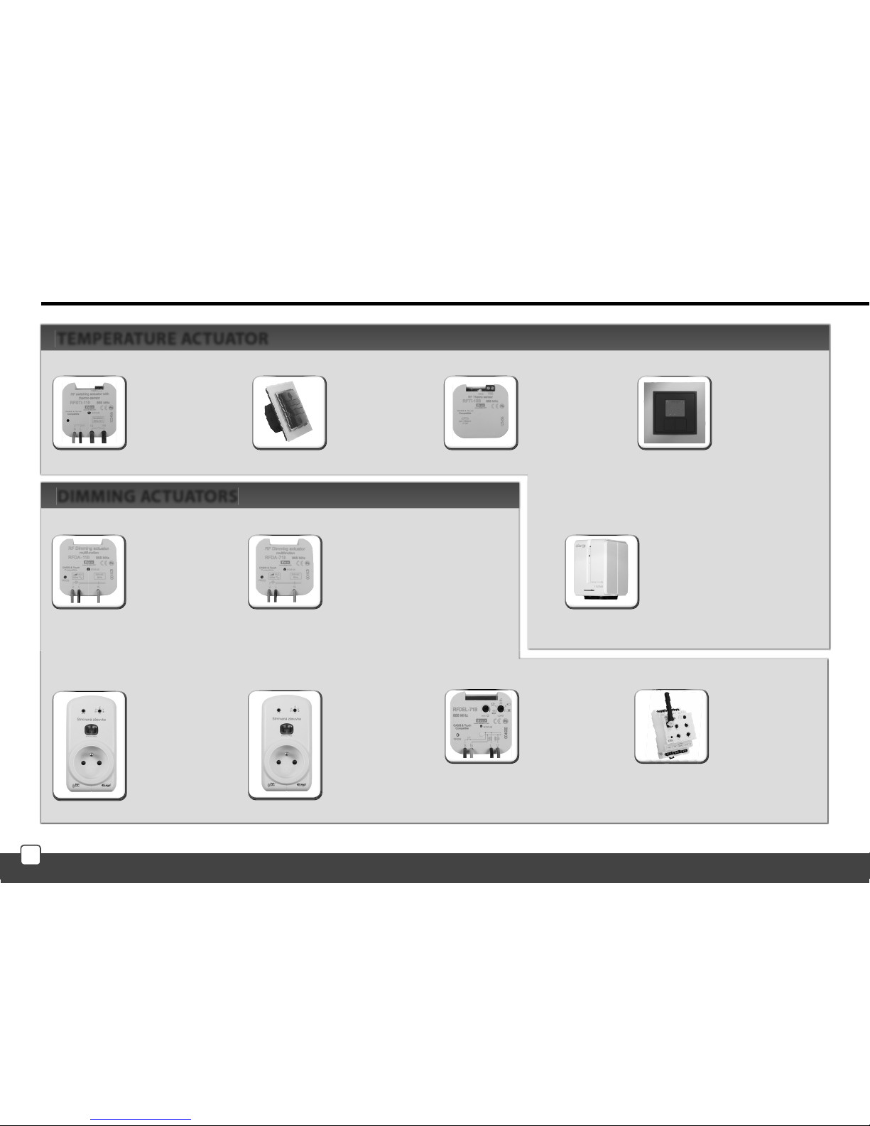
RFSTI-11B
wireless switching actuator
with temperature sensor
in design to installation box,
230V AC
RFSTI-11/G
wireless switching actuator
with temperature sensor
with manual
control buttons directly
on the unit, 230V AC
RFTI-10B
wireless temperature sensor
1 x CR 2477 3V battery
RFTC-10/G
digital temperature
controller
2 x 1.5V AAA batteries
TEMPERATURE ACTUATOR
Overview of wireless RF Control devices
RFDA-11B
single function
dimming actuator
1 light scene,
function OFF, 230V AC
RFDSC-11
single-function dimmed
socket
1 lighting scene
function OFF, 230V AC
RFDEL-71B
multifunction dimming
actuator
7 functions, 230 V AC /
250VA
Dimmed load: R, L, C,
LED, ESL
RFDA-73M/RGB
used to dim LED strips and
RGB LED strips, possible
other LED loads
RFDA-71B
multifunctional dimming actuator
7 functions,
AC 230V / 250V
RFDSC-71
multifunction dimmed socket
7 functions,
230 V AC / 250VA
DIMMING ACTUATORS
RFATV-1
measures the temperature in
the given zone and provides
wireless control of the radiator
(heater) valve
6
E
N
Characteristics of RF Touch
Control Unit of the wireless system RF Control - RF Touch provides intelligent control of the RF units.
It can be used for:
Central control of all units from one place
Complete overview (visualization) of the current status of units (appliances / equipment)
Features:
sends command to temperature, switching, dimming and shutter actuators
accepts commands from the transmitters, actuators, temperature sensors and detectors
processing programs for heating and regulation
Design:
RF Touch-B ts in the round installation box with a supply voltage of 100 - 230 V AC
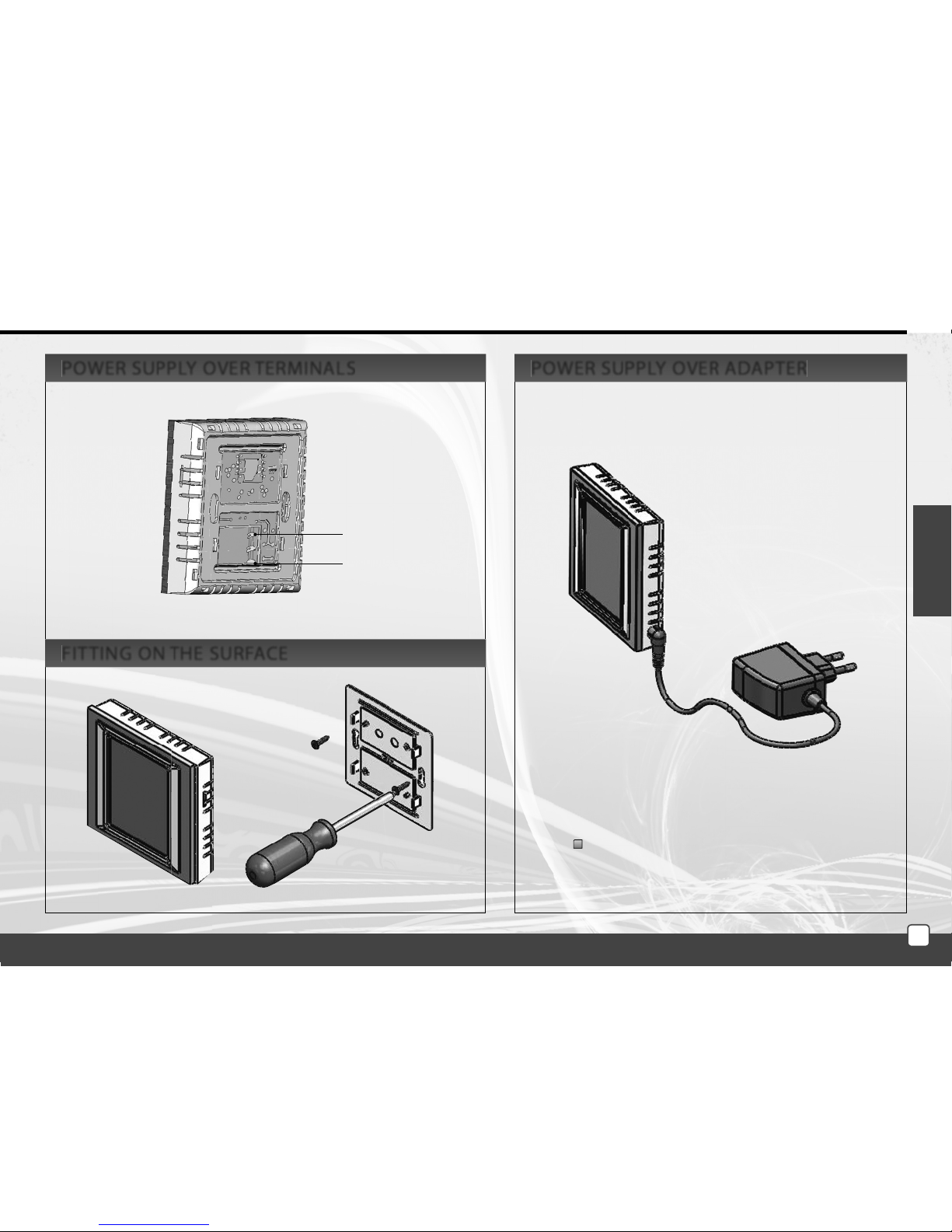
RF Touch-W for surface mounting with power supply from the back side: 100 - 230 V AC or from the side (via jack):
12 V DC
3.5 inch color touch screen - no mechanical buttons
RF Touch frames in the base plastic (white, black) or luxurious design Logus90 (glass, metal)
Color of the interframes - white, ivory, ice, mother of pearl, aluminum, silver
Colors of the boxes (only for RF touch-W) - white, ivory, dark gray, light gray
Backup time in case of power failure is 48 hours
40 actuators and 30 OASIS detectors can be assigned to each RF Touch unit
RF Touch can be combined with units of RF Control marked as Oasis & Touch Compatible
7
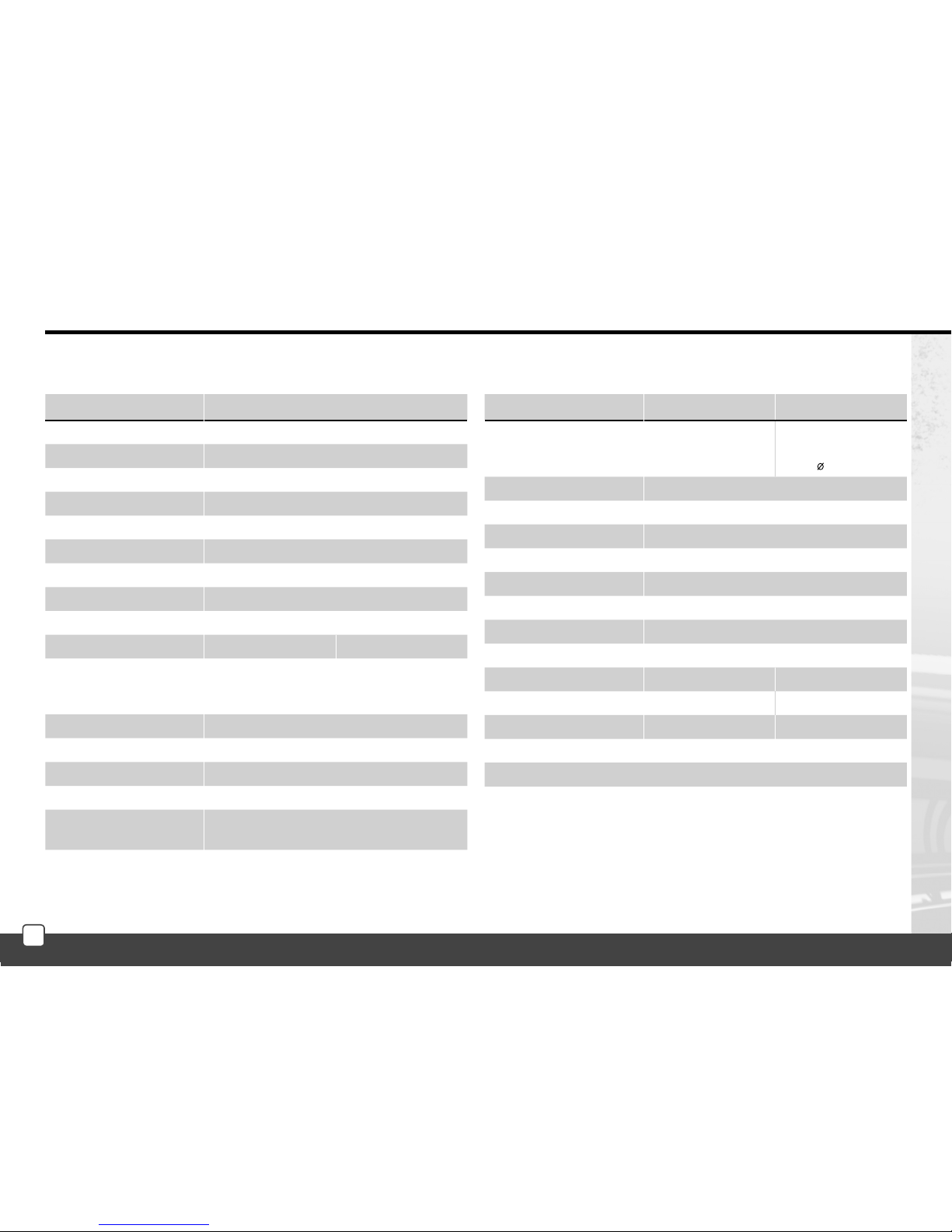
Technical parameters
RF Touch-B RF Touch-W
Connection
push-in
screwless terminal
push-in or jack
2.1 mm
Max. cross section of wires: max. 2.5 mm
2
/ 1.5 mm2 with socket
Operating conditions
Operating temperature: 0 ... +50°C
Storage temperature: - 20 ... +70°C
Protection: IP 20
Overvoltage category: III.
Pollution degree: 2
Operating position: arbitrary
Installation: installatin a box wall box installation
Dimensions: 94 x 94 x 12 mm 94 x 94 x 24 mm
Weight **: 127 g 175 g
Standards: EN 60730-1
* adapter is included for RF Touch-W
** weight with plastic frame
Technical parameters
RF Touch-B RF Touch-W
Display
Type: color TFT LCD
Resolution: 320 x 240 pixels / 262,144 colors
Aspect ratio: 3 : 4
Visible area: 52.5 x 70 mm
Backlight: active (white LED)
Touch screen: resistive 4-wire
Display: 3.5”
Control: Touch sensitive
Power supply
Voltage /
speci c current:
100 - 230 V AC
from the back side
100 - 230 V AC
from the side 12 DC *
Power consumption: max. 5 W
Power supply connector: A1 - A2
Control
Range up to: 100 m
Minimal range
RF Touch – actuator: 1 m
Frequency: 868 MHz
Technical specifications
8
A1
100 - 230V AC
A2
E
N
RF Touch-W
adapter included with RFTouch-W
POWER SUPPLY OVER ADAPTERPOWER SUPPLY OVER TERMINALS
FITTING ON THE SURFACE
9
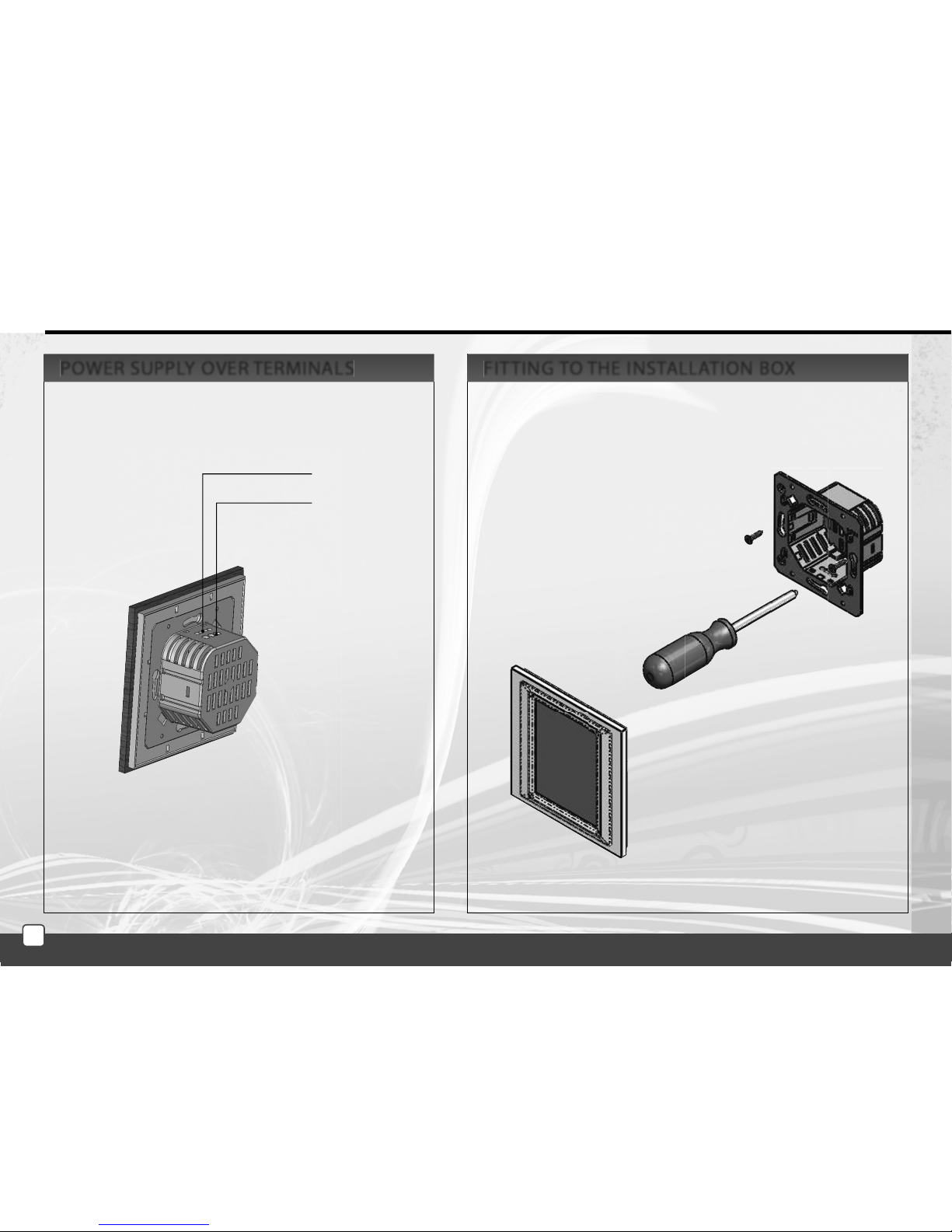
A2
AC 230V
A1
RF Touch-B
FITTING TO THE INSTALLATION BOXPOWER SUPPLY OVER TERMINALS
10
OK
.
abc
A/a
_
a/1
OK
C
OK
0-10V
E
N
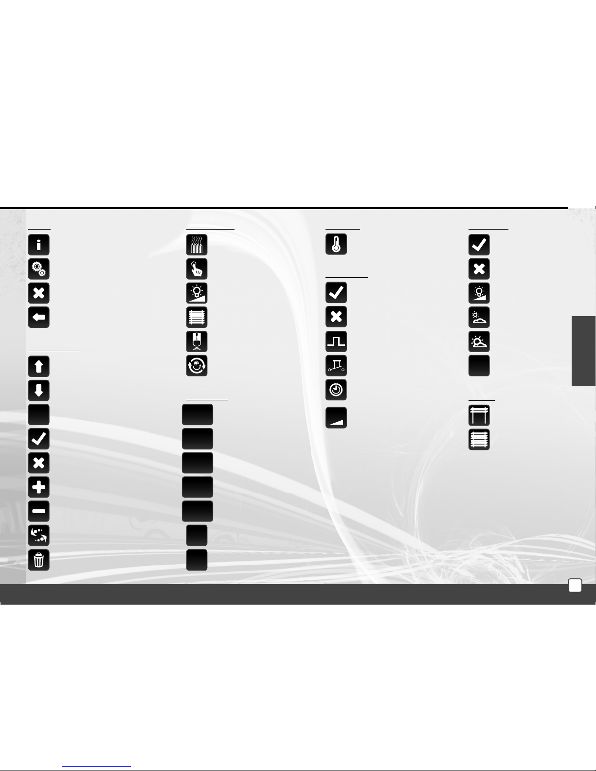
Description of Control Icons
RF Touch version Information
and number of assigned units
settings
back to the home screen
step back
delete
name/adressof the actor(s)
Basic
add
edit/remove
scroll up
scroll down
con rm
Setup Menu
yes/selected
no/not selected
con rm
dot
letters
small/capital letters
space
switch - the letters / numbers
Temperature regulation
Switching
Dimming
Blinds
Detectors
Quick kontrol
Main menu
erase previous
Keyboard
temperature
Switching
impuls
button
time function
- delayed switch on
- delayed switch o
Heating
switch ON
switch OFF
switch ON
switch OFF
dimming
light inclination
light declination
Dimming
lower blinds
rise blinds
Blinds
con rm
regulation
11
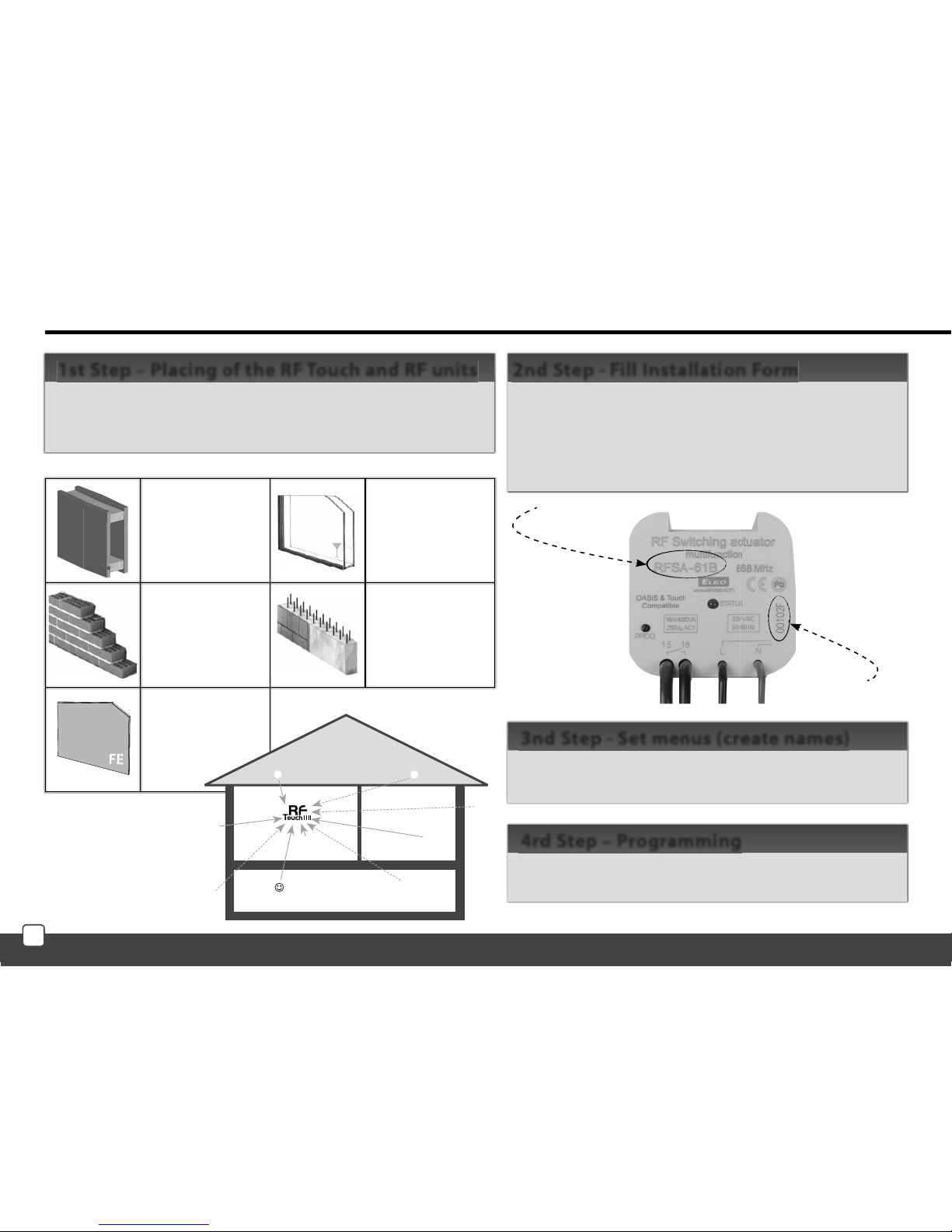
Basic Steps for Successful Programming
Keep in mind that the radio signal range of RF installation
depends ON building construction, materials and placing of all
units.
1st Step – Placing of the RF Touch and RF units
- device name that you want to manage (to create a menu)
- the names of units (for the correct classification of the
group, for example: RFSA-61B)- addresses of units (to
identify the actuator, for example: 577515)
Installation form can be found at the end of this manual.
2nd Step - Fill Installation Form
Name
Adress
Create a list of names of the controlled device in the
Settings / Menu (create name).
3nd Step - Set menus (create names)
Programming of the RF units with RF Touch is carried out in
the Settings / Programming menu.
4rd Step – Programming
brick wall
60-90 %
Wooden structures
with plasterboard
plates
80-95 %
reinforced concrete
20-60 %
metal plates
0-10 %
standard glass
80-90 %
E.g. RFSA-61B
E.g. 577515
Transmission of radio-frequency signals through various materials.
12
E
N
fig. 1
fig
. 1
fig. 4
fig. 4
fig. 6
fig. 6
fig. 7
fig. 7
fig. 8
fig. 8
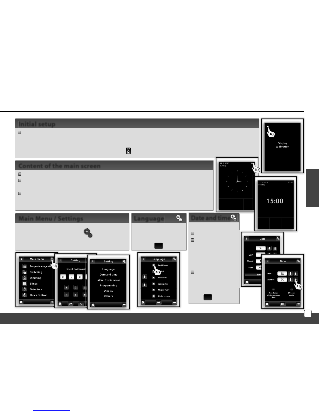
Settings (Fig.7-8):
Date and Time
automatic
transition between
winter / summer
time (for time
Zone GTM +01:00)
Format settings
hours (12h / 24h
mode)
To save Settings
press OK.
Date and time
SETUP
Selection of required
Language - Figure 6.
Save setting by
pressing OK.
Language
The settings menu can be opened by touch in the upper
right corner screen on the symbol
by
to
and insertion of
password (it´s setting from production – 1111) ( g. 4-6),
which you can change
everywhen.
Main Menu / Settings
When the RF Touch is switched on for the rst time, you will be automatically redirected to the display calibration screen. Touch screen can be controlled by the light touch (of about0.5-1s) in the desired location. On the
screen (Fig. 1) then appears cross in each corner of the screen, which need to be pressed twice. This will calibrate
the device. The display then shows the RF logo icon
and then touch icon signalizing scanning of the actuators.
Initial setup
date
time (touch in the upper right corner of the display will switch between analog
- digital clocks (Figure 2 - Figure 3)
display at the bottom of the screen is customable, eg: heating mode, a often used device ...
Touch the clock area to enter the Main menu. If you want to get to the main menu from
sleep mode, you need to touch the screen anywhere.
Content of the main screen
fig. 2
fig. 2
fig. 3
fig. 3
fig. 2
fig. 2
fig. 5
fig. 5
13
SETUP
fig. 1
fig. 1
fig. 2
fig. 2
fig. 3
fig. 3
fig. 4
fig. 4
fig. 5
fig. 5
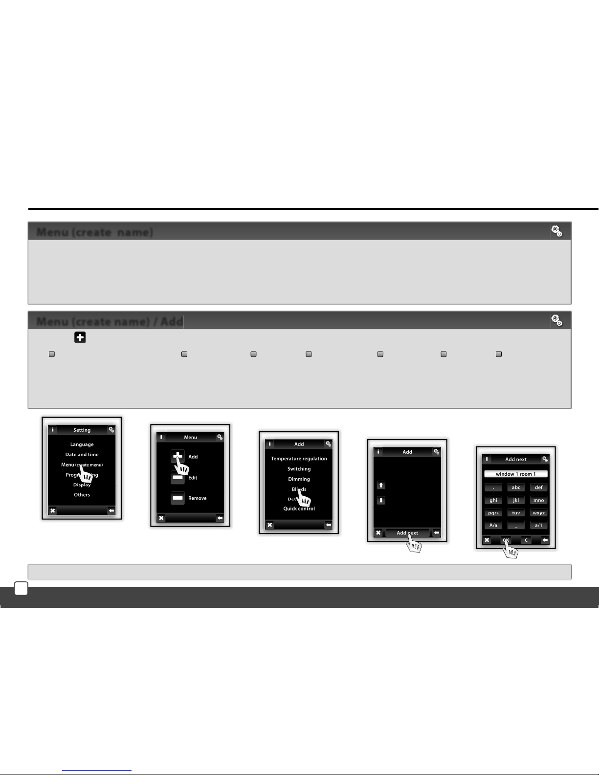
Note: Actuator RFTI-10B can be connected with two temperature sensors. For each sensor, you can create your own name.
Press the Add icon (Fig. 2) to show a selection of sections (Fig. 3):
Temperature regulation Dimming Blinds Switching Control Speed Detectors
Choose the section where you want to add the device name and type your own text (max. 20 characters).
Example 1: If you want to control the blinds - Place the name to the section of the blinds (Fig.3-5).
Example 2: If you want to control a group of blinds together, first create all the blinds names in the blinds section and then create new name for group control in Quick
control section.
Menu (create name) / Add
Menu (create name) is used to add, edit or remove the names of the controlled device. In this menu (Figure 1) you need to first
create your own device names for the sections you want to control.
Creating names is important for successful programming of the RF Touch. For each actuator, which is involved in the installation
you have to create unique name.
The content of this menu is not set at the factory.
Menu (create name)
14
 Loading...