

Elko RFPM-2M Assembly And Installation Manual
02-5/2018 Rev.0
RFPM-2M
Made in Czech Republic
1/7
60 - 90 %
80 - 95 %
20 - 60 %
0 - 10 % 80- 90 %
☺
☺
☺
☺
☺
RFRP-20
PULS 1 PULS 2
S0+
S0-
TARIF
TARIF
router
1
2
3
4
5
6
7
8
10
11
12
13
9
15
7
14
STORAGE
ELKO EP, s.r.o. | Palackého 493 | 769 01 Holešov, Všetuly | Czech republic | e-mail: elko@elkoep.com
EN
Support: +420 778 427 366
www.elkoep.com
Energy gateway
EN
Charakteristika
• The energy gateway is a central device for assessing energy consumption (electricity, water, gas).
• • It acts as an interface between the pulse converter RFTM-1 and your smartphone.The Energy
Gateway allows you to connect up to 8 pulse transducers.
• Connection to the data network is made by means of LAN Ethernet connector or wirelessly via a
Wi-Fi network.
• The monitored data is stored inside the unit (it can also be sent to external storage - cloud).
• By means of the application iHC and cloud connection, it is possible to maintain online access to
data and monitoring history.
• Up to 4 tariff meter readings of electricity consumption, which can be displayed in the form of kWh
or financial costs.
• Option of setting reaction to specific consumption to switch the output on or off (RFSA-6x and
CU3).
• The unit enables connecting up to three current transformers CT50 to each other for measuring
electricity.
• Direct connection to iNELS BUS using integrated CIB terminals.
• 3-module design, mounted on a DIN rail into the switchboard.
• The supply includes an internal antenna AN-I, if the unit is installed in a metal switchboard, you can
use the external antenna AN-E to enhance the signal.
• The device supply voltage is provided from monitored phases.
• Range up to 100 m (in open space), if the signal between the controller and the user is weak, use
the signal repeater RFRP-20 or protocol component RFIO2 that support this feature.
• Communication frequency with bidirectional protocol iNELS RF Control.
• In order to communicate with the gateway, it must be connected to the local network using the
RJ45 Ethernet connector or wirelessly over the WiFi network.
• The Energy Gateway stores the measured data directly on the internal memory storage. Online
data and history can be viewed through iHC applications (MAIRF and MIIRF) or cloud connections
on the ELKO Cloud site. The last option is to display the measured values directly on the RFPM-2
web interface.
• Measurement of power consumption can be distinguished by up to four tariffs that can be
displayed in kWh or financial costs.
• Other benefits include the ability to set the response to a specific consumption. An example may
be to switch off or on the RFSA - 6x and CU3 outputs.
• The energy gate takes usually 10 minutes, but not more than 1 hour.
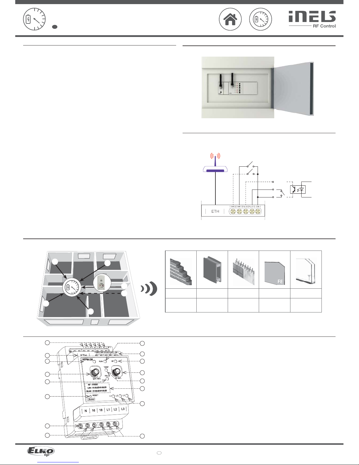
Assembly
mounting into switchboard
Connection
connection to the tariff
(potential free contact)
CAUTION! Do not connect the HDO contact)
Description, Indication
1. Terminals for connection of current
measuring probes
2. Connect Ethernet
3. Storage operation indication
4. WiFi antenna
5. Relay switch indication
6. RESET button:
- Enter the bootloader - turn off the power,
press the but ton and hold the button> 2s
when the power is on
- Return to fac tory settings - power off , press
button and hold power button> 10s
7. Voltage and voltage terminals
8. Relay output
9. Supply voltage indication / unit status:
- Lit - STOP status
- Flashes - RUN status
10. Pulse and tariff inputs
11. RF communication indication
12. RF antenna
13. Tariff indication:
- TARIFF 1: red
- TARIFF 2: green
- TARIFF 3: blue
- TARIFF 4: Yellow
14. RF, LAN and WLAN addresses
15. Phase status indication L1, L2, L3:
- Failure (redundancy): red
- Phase active: green
- Unmonitored phase: LED off
Radio frequency signal penetration through various construction materials
brick walls
wooden structures
with plaster boards
reinforced
concrete
metal partitions common glass
02-5/2018 Rev.0
RFPM-2M
Made in Czech Republic
TARIF 1/2
router
N
16
18
L1
L2
L3
I1
I1*I2I2*I3I3*
N
L1
L2
L3
max.
F16A / 250 V
RF
0 0 0 0 0 , 0 0 6
RFPM-2MRFTM-1
N
16
18
L1
L2
L3
I1
I1*I2I2*I3I3*
N
L1
L2
L3
max.
F16A / 250 V
N
16
18
L1
L2
L3
I1
I1*I2I2*I3I3*
N
L
max.
F16A / 250 V
CT50
CT50
CT50
CT50
2/7
ELKO EP, s.r.o. | Palackého 493 | 769 01 Holešov, Všetuly | Czech republic | e-mail: elko@elkoep.com
EN
Support: +420 778 427 366
www.elkoep.com
Energy gateway
EN
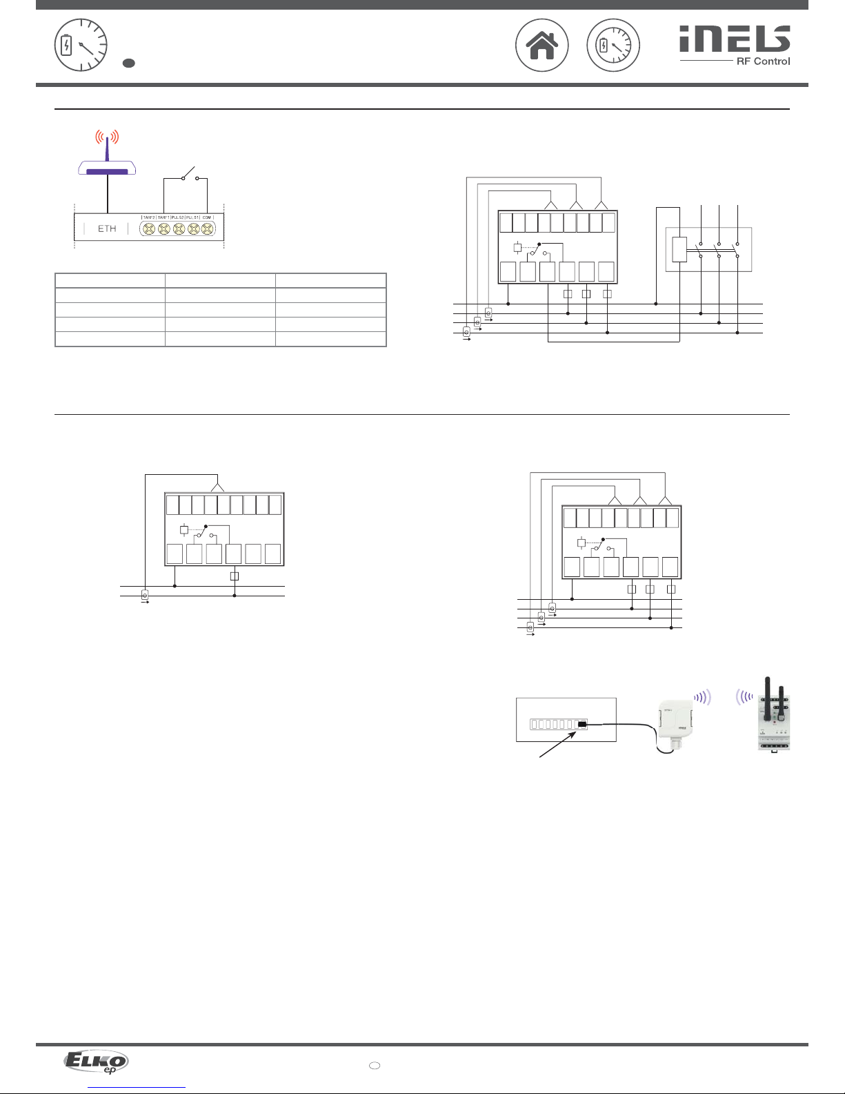
Tar i ff
Example of wiring for two-wire connection
TARIF
TARIF 1
TARIF 2
TARIF 3
TARIF 4
Indication
illuminated red LED
illuminated green LED
illuminated blau LED
illuminated yellow LED
Linking
Without wiring
TARIF 1 - COM
TARIF 2 - COM
TARIF 1 - COM, TARIF 2 - COM
An example of using the output relay
- phase failure monitoring
- Excessive consumption
- Undercover ....
Contactor
Methods of sensing meters
1-phase wiring 3-phase wiring
Note: The arrow inside the CT50 current transformer must be directed to the appliance.
I1, I2, I3 - red wire
I1*, I2*, I3* - black wire
I1 - red wire
I1* - black wire
• LS - LED sensor
- The LED sensor scans LED impulses on the meter, which indicates consumption by fl ashing.
- The LED sensor is particularly suitable for power meters that support LED pulse sensing (the LED on the meter is
marked “imp”).
- The sensor‘s scanner is affi xed with glue above the LED diode of the meter signaling indication of consumption.
- The sensor is connected to the internal terminal of the RFTM-1 converter.
• MS - Magnetic sensor
- The magnetic sensor scans movement of the numeral, upon which a permanent magnet is placed.
- The MS sensor is particularly suitable for gas meters that support magnetic sensing.
- The device sensor is fastened by gluing over the last number of the dial unit measured (it may be designated on the
silver refl ective element number 6).
- The sensor is connected to the internal terminal of the RFTM-1 converter.
• WS - Magnetic sensor water meter
- A magnetic sensor that detects the pulse that is created by each rotation of the magnet placed on the unit dial meter.
- The WS sensor is especially suitable for water meters that support magnetic sensing.
- The sensing sensor is glued over the circular unit face of the gauge (the scanning dial is diff erent from the other
indicators, e.g. the white arrow wheel).
- The sensor is connected to the internal terminal of the RFTM-1 converter.
Note: The standard supplied length of 1.5 m can be custom ordered in an extended version of up to 5 m.
Sensor
• Scanning with sensor (MS / WS / LS) and device RFTM-1
• Scanning with the current transformer CT50
02-5/2018 Rev.0
RFPM-2M
Made in Czech Republic
0 0 0 0 0 , 0 0
RFPM-2M
S0+ S0 -
RF
0 0 0 0 0 , 0 0
RFTM-1 RFPM-2M
3/7
ELKO EP, s.r.o. | Palackého 493 | 769 01 Holešov, Všetuly | Czech republic | e-mail: elko@elkoep.com
EN
Support: +420 778 427 366
www.elkoep.com
Energy gateway
EN
• Scanning with output "S0" and RFTM-1 • Scanning with output "S0"
Impulse output
• S0 - contact, open collector, reed magnetic contact
- Impulse output meters marked "S0" connected to the GND and DATA1 terminals on the RFTM-1 sensor.
- When polarization is indicated on the meter, the terminals S0 + and S0- must be distinguished when
connected to the "S0" impulse output.
Impulse output
Notice
- RFTM-1 / RFPM-2M / sensors (LS, MS, WS) do not af fect the consumption meter and do not affect the measurement of the measured quantity.
- Electricity meter s, water meters and gas meters are the property of energ y suppliers. Without their knowledge and permission, they are not allowed to inter fere with internal connec tions (seals, supply
lines, etc.).
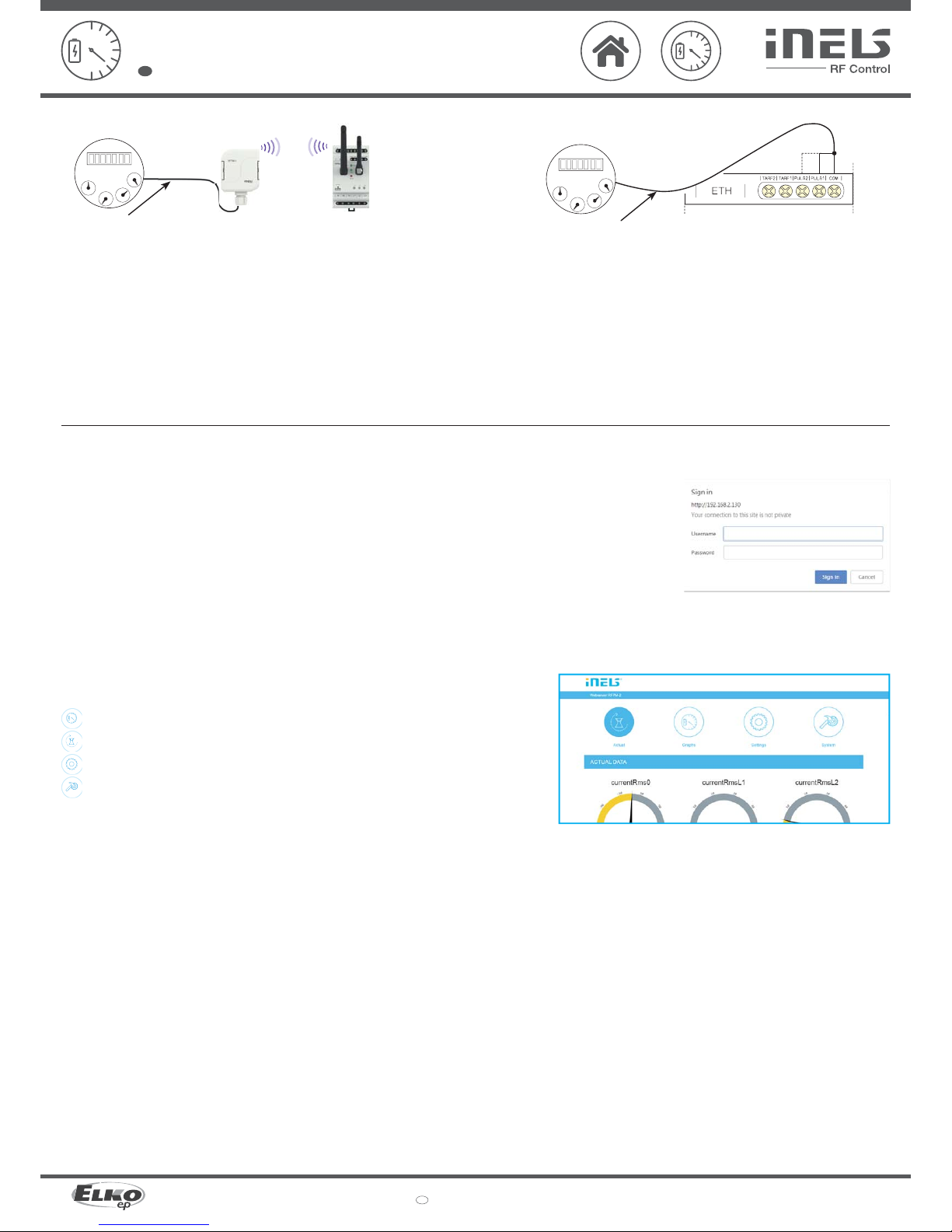
Installation of RFPM-2M
Connect the RFPM-2M to the power supply (can be powered from the monitored phase).
Use an Ethernet cable to connect it to your PC / Router. By default, static IP address 192.168.1.2 is set on RFPM-2M.
If you do not have the same IP range on the router, you need to set the same IP address range in your PC (Control Panel \
Network and Internet \ Network Connections \ Local Area Connection \ Properties \ Version 4 Protocol \ Use the following IP
address \ 192.168.1.10 - to make RFPM-2M available for confi guration.
After this, open a web browser. Enter the IP address 192.168.1.2.
The RFPM-2M Web Environment opens, where you can confi gure your device.
RFPM-2 will require login through your username and password, which are set by default:
Name: admin
Password: admin
Pro úspěšné nastavení času z NTP serveru je nutné RFPM-2 po nastavení jeho sítě restartovat.
Note: Press and hold the RFPM-2 button for 10 seconds on the front panel of the instrument (RESET). The IP address and login
information will return to the factory settings.
Once logged in, you'll see an interface for managing and displaying measured data in your browser.
There are four tabs in the top bar:
Displaying current statuses
Graphical display of measured values
Setting the RFPM-2M
System Settings
 Loading...