

Page 1

USER’S MANUAL
WIRELESS CONTROLLER
WITH OLED DISPLAY
mo 01.01.10 12:54
Rooms
Scenes
Favourite
EXIT SELECT
Page 2
2
RF Pilot User’s Manual
Congratulations on purchasing our RF Pilot Remote Controller that serves
as an element of the RF Control wireless system.
RF Pilot offers you:
comfortable control with elegant design
activation of household appliances and devices
light dimming and creation of light scenes
control of roller blinds/shutters, garage doors, awnings
control of multiple electrical appliances with a single press
wireless communication without unnecessary cabling
Page 3
3
RF Pilot User’s Manual
Content:
Before You Start ...............................
Characteristics .................................
Overview of Wireless Elements ........
Technical Parameters .......................
Device Description; Insertion of
Batteries ...........................................
Basic Steps ........................................
Controller Activation ........................
Settings Menu
- Language .......................................
- Date and Time ...............................
- Actuators .......................................
- Rooms ............................................
- Scenes ............................................
4
5
6
8
9
10
12
13
13
15
20
22
- Favourite .......................................
- Device Reset ..................................
Quick Control ...................................
Basic Menu - Controls .......................
- Rooms ............................................
- Actuator Function ..........................
- Scenes ............................................
- Favourite .......................................
What to Do When .............................
Universal information ......................
Important Information ....................
Installation Form ..............................
25
28
29
31
32
33
36
37
38
39
40
42
Page 4
4
RF Pilot User’s Manual
Before You Start...
The User’s Manual provides information for the installation and use of the device. The Manual is always included in the
package. The device may only be installed and connected by persons with requisite professional qualications who have become
thoroughly familiarized with this Manual and the functions of the device. Trouble-free operation also depends on the previous method
of transportation, storage and handling. Should you become aware of any signs of damage, deformation, malfunction or of any
missing parts, do not install this product and return it to the vendor. After the expiry of its service life, the product and all its parts
must be disposed of as electronic waste. With consideration to the transmission of the RF signal, ensure that RF components are
suitably located in the building where the device is to be installed. The RF Control system must only be installed in indoor areas. The
device has not been designed for outdoor use or use in moist environment, it must not be installed in metal distribution boxes and
plastic distribution boxes with metal doors as this would prevent the transmission of the radio frequency signal. RF Control is not
recommended for the control of devices providing for vital life functions or for the control of risk devices such as lifts, pulleys etc. - radio
frequency transmission could be hampered with an obstacle, interfered with, the transmitter battery may become depleted etc. thus
disabling the remote control. Not suitable for use in industrial environment.
Page 5
5
RF Pilot Characteristics
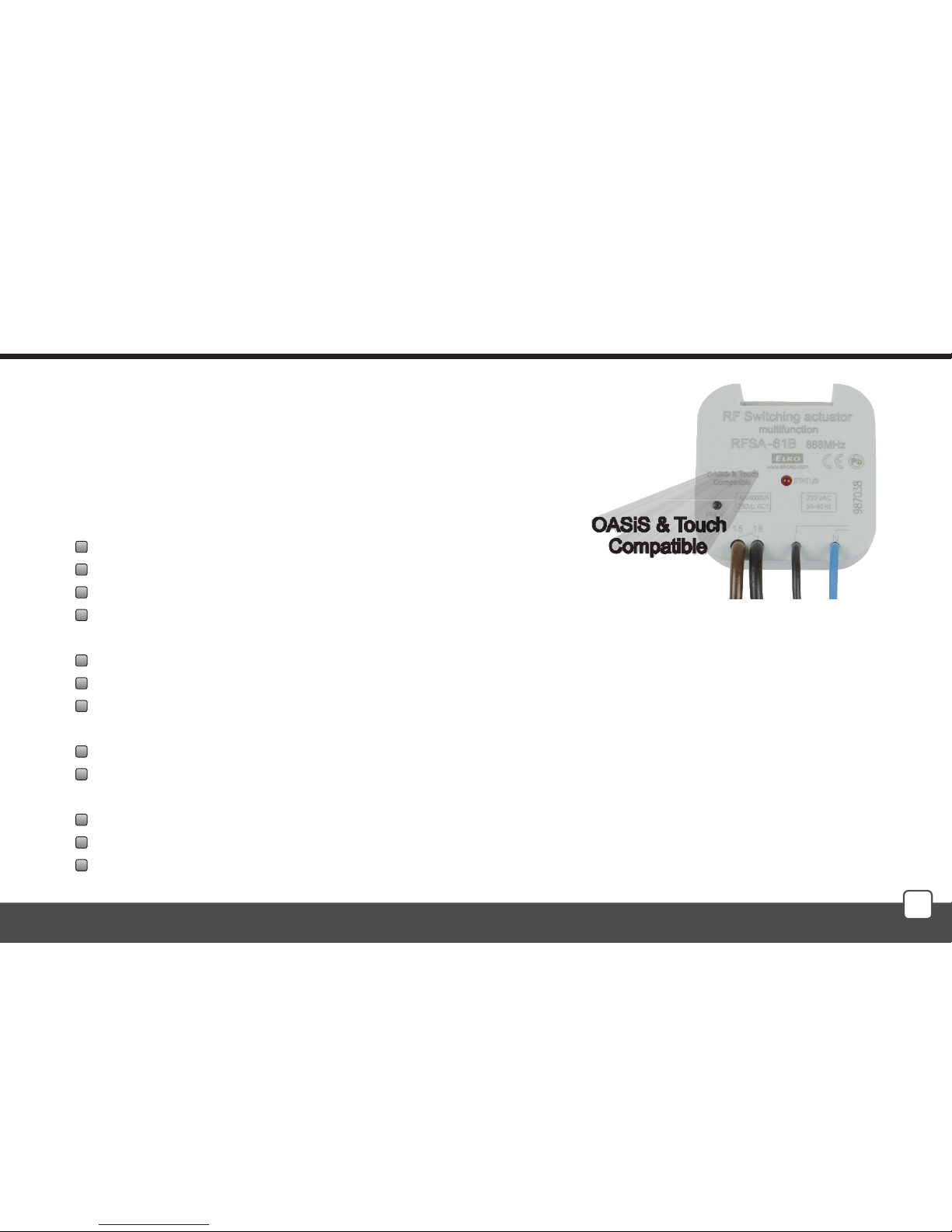
The Remote Controller of the RF Control wireless system enables
intelligent control of RF units.
Central control of RF Control actuators marked with an appropriate label
Sending commands to switching, dimming and roller blind/shutter actuators
RF Pilot measures and displays temperature in the surrounding area
Wireless Remote Controller RF Pilot can be programmed for up to 40 RF Control actuators
You can create your own menu and name the RF Pilot controlled device as requested
The “Scene” mode enables control of multiple actuators - multiple devices controlled with a single press
You can include the most frequently used devices in your “Favourite” menu and control them immediately after switching on
the RF Pilot
Range up to 200m
Operates on the frequency 868 MHz
Wireless Remote Controller RF Pilot with elegant design and OLED display
colours: white, anthracite
Battery supply 2xAAA with life cycle up to 3 years
Page 6

6
Overview of wireless elements of RF Control
RF Touch-W
for surface installation
100 - 230V AC or
adapter (external)
12V DC
RF Touch-B
for installation
into installation box
100 - 230 V AC
RF Pilot
Remote Controller
colours: white,
anthracite
RFDA-11B
single-function
dimming actuator
1 light scene,
OFF function, 230V AC
RFDAC-71B
actuator with analogue
output 0(1) - 10 V
1 x switching contact 16 A,
7 functions, 230V AC
Thermo-valve
for thermo-drive regulation
supplied to order
together with RFDAC-71B
Dimmable ballast
for dimming of uorescent
lamps, supplied to order
together with RFDAC-71B
RFDA-71B
multifunction
dimming actuator
7 functions,
230 V AC / 250VA
ANALOGUE ACTUATOR
CONTROLLER CENTRAL WIRELESS UNIT
DIMMING ACTUATORS
Page 7
7
Overview of wireless elements of RF Control
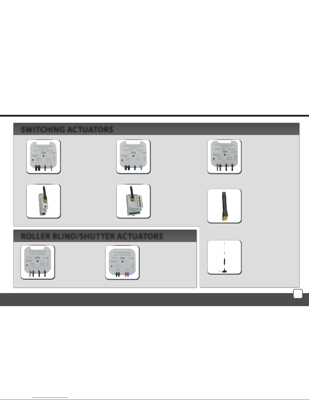
RFJA-12B/230V
Roller blind/shutter
actuator
2 x switching 8A
relay with protection
230V AC
RFJA-12B/24VDC
Roller blind/shutter
actuator
contactless switching
12-24V DC
RFSA-11B
single-channel
single-function
switching
actuator
1 x switching 16A
230V AC
RFSA-61B
single-channel
multifunction
switching actuator
1 x switching 16A
230V AC
RFSA-62B
two-channel
multifunction
switching actuator
2 x switching 8A
6 functions, 230V AC
RFSA-61M
single-channel
multifunction
switching actuator
1x switching 16 A
6 functions,
230V AC
RFSA-66M
six-channel
multifunction
switching actuator
3 x switching 8 A
3 x switching 8 A6
functions, 230V AC
Angle antenna
for plastic distribution
boxes - supplied as
standard with RFSA-61M,
RFSA-66M, RFSG-1M
Angle antenna
for metal distribution
boxes - supplied
to order with RFSA-61M,
RFSA-66M, RFSG-1M
SWITCHING ACTUATORS
ROLLER BLIND/SHUTTER ACTUATORS
Page 8
8
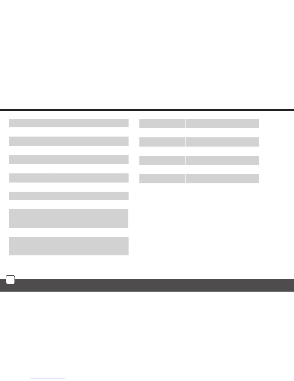
Technical parameters of RF Pilot
Display
Type:
Resolution:
Side ratio:
Visible surface:
Backlight:
Diagonal:
Control:
Power supply
Power supply:
Service life:
Control
Range in open area:
Frequency:
colour OLED
128 x 128 pixels / 262,144 colours
1:1
26 x 26 mm
self-illuminating text
1.5“
direction button, control buttons
2 x batteries 1.5V AAA *
approx. 3 years, according to the
frequency of use and battery type
to 200 m
868 MHz
Other data
Operating temperature:
Storage temperature:
Protection:
Working position:
Dimensions:
Weight:
Related standards:
0 .. +55 °C
-20 ..+70 °C
IP20
Any
130 x 41 x 18 mm
61 g
EN 60730-1
* batteries are included in the package
Page 9
9
+
+
-
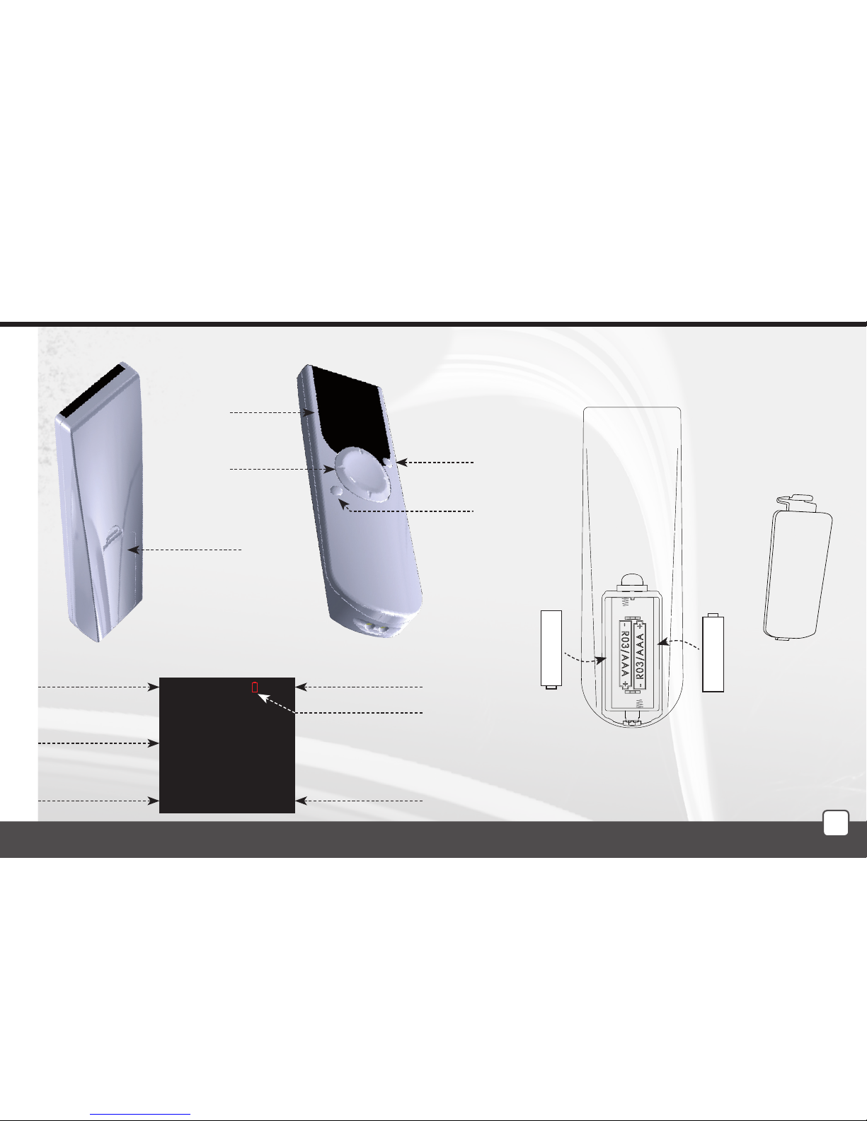
Device description; Insertion of batteries
Display description - basic display
Device description Battery insertion
Display
Direction
button
Control
button T1
Control
button T2
TimeDate
Enter the menu
Quick Control
options
Battery
cover
Low battery
indicator
Remove the battery cover and insert two R03/AAA batteries as
indicated.
Battery
cover
Device
mo 01.01.10 12:54
Favourite 1
Favourite 2
Favourite 3
Favourite 4
Favourite 5
Favourite 6
Favourite 7
Temp.: 23C MENU
The memory has an independent power supply. Any custom
adjustment (except for time and date) will remain.
After inserting the batteries, the RF Pilot name and the rmware
number will appear on the initial screen.
Current temperature
display
Page 10
10
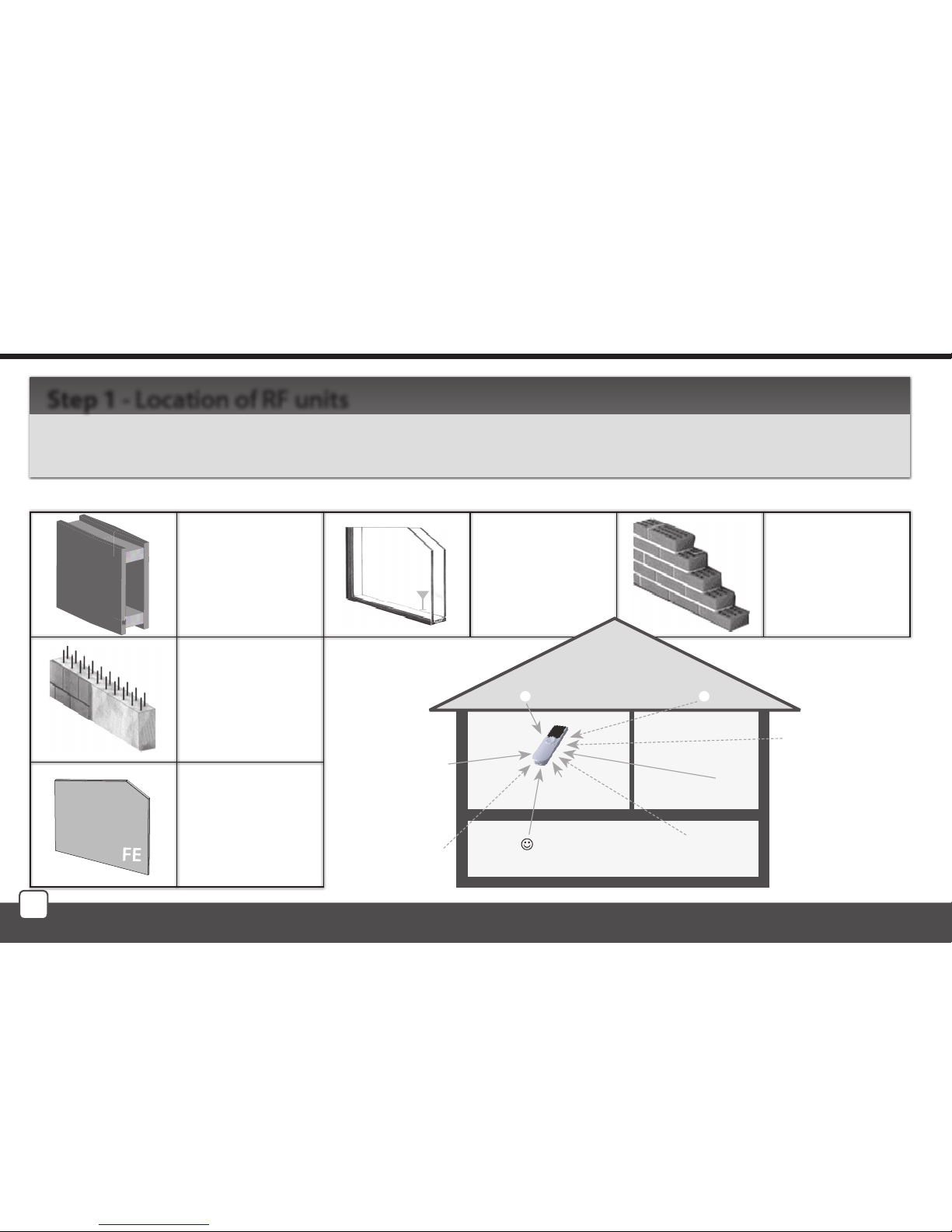
Keep in mind that the radio signal range for RF installations depends on the building structure, materials
used and the manner of unit location in the area.
Step 1 - Location of RF units
brick walls
60-90 %
wooden structures
with plaster boards
80-95 %
reinforced concrete
20-60 %
metal partitions
0-10 %
common glass
80-90 %
Basic Steps for Successful Programming of RF Pilot
Radio frequency signal penetration through various construction materials
Page 11
11
Basic Steps for Successful Programming of RF Pilot
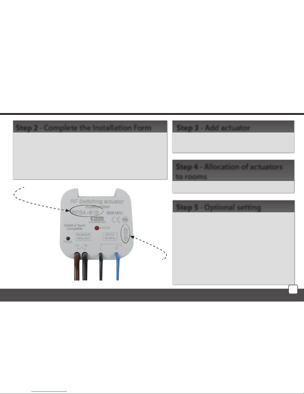
- name of the device you want to control
- names of units (e.g.: RFSA-61B, ...)
- addresses of units (e.g.: 577515, ...)
(The Installation Form is included at the end of the
Manual).
Step 2 - Complete the Installation Form
Add actuators and their addresses into the
Controller memory.
Step 3 - Add actuator
Allocation of actuators to rooms.
Step 4 - Allocation of actuators
to rooms
Rename actuator according to your requirements.
Test of the range and RF signal quality.
Rename Room.
Create Scene.
Saving most frequently used Actuators / Rooms / Scenes in the Initial Screen Favourite
as shortcuts.
Step 5 - Optional setting
Name
E.g.: RFSA-61B
Address
e.g.: 577515
Page 12
12
T1
T2
T1
T2
Controller Activation
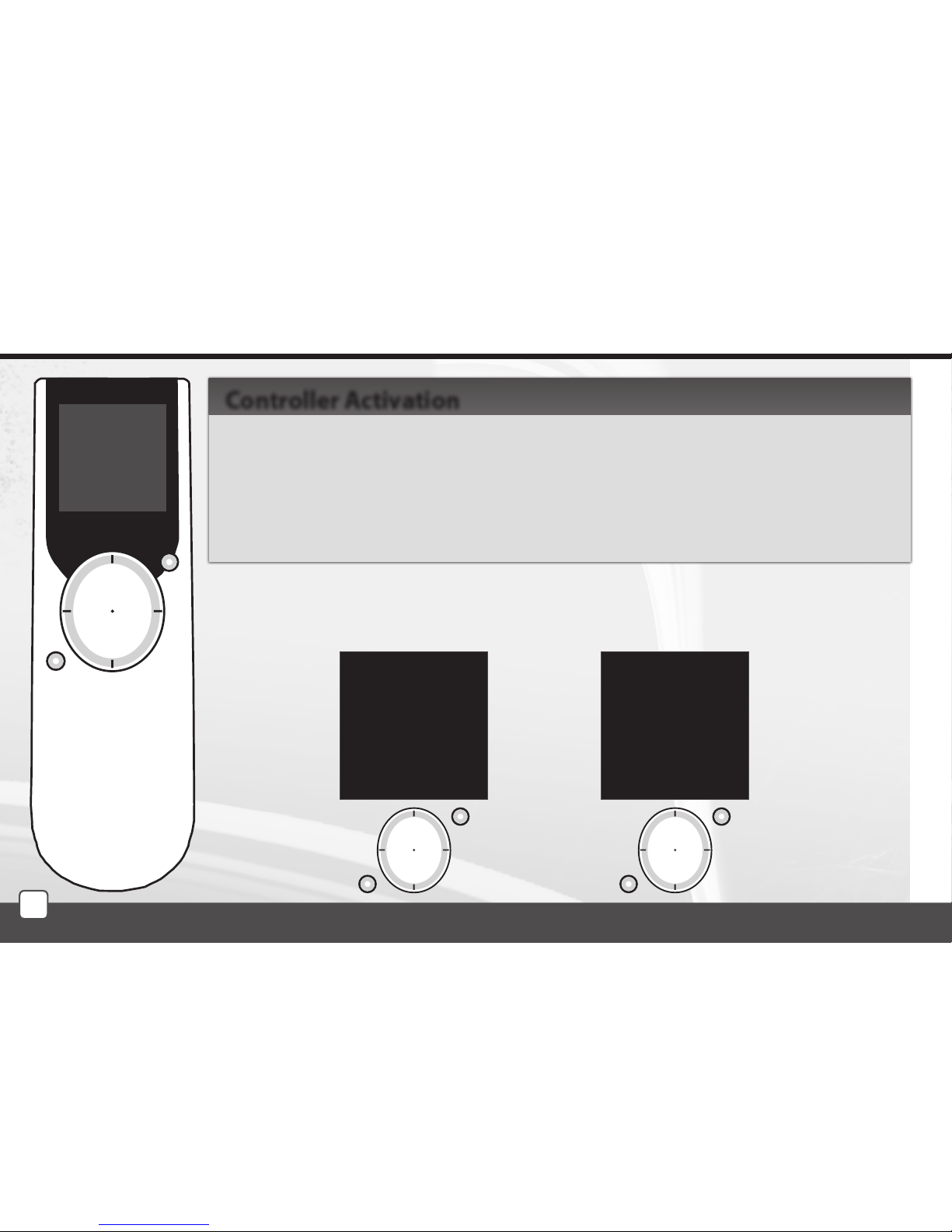
As standard, the display is in the sleep mode - no information is displayed (Fig. 1).
Press any button briey to display the Initial Screen (Fig. 2).
Press T1 to enter the Basic Menu (Fig. 3).
Note: When using the controller, 10 seconds after pressing any button, the RF Pilot switches to the sleep
mode. In the Settings Menu, it switches to the sleep mode 40 seconds after pressing any button.
Controller Activation
Fig. 3Fig. 2
mo 01.01.10 12:54
Rooms
Scenes
Favourite
EXIT SELECT
mo 01.01.10 12:54
Favourite 1
Favourite 2
Favourite 3
Favourite 4
Favourite 5
Favourite 6
Favourite 7
Temp.: 23C MENU
Fig. 1
Page 13
13
T1 T1
T2
T2T2
Settings Menu / Settings - Language
T1T1
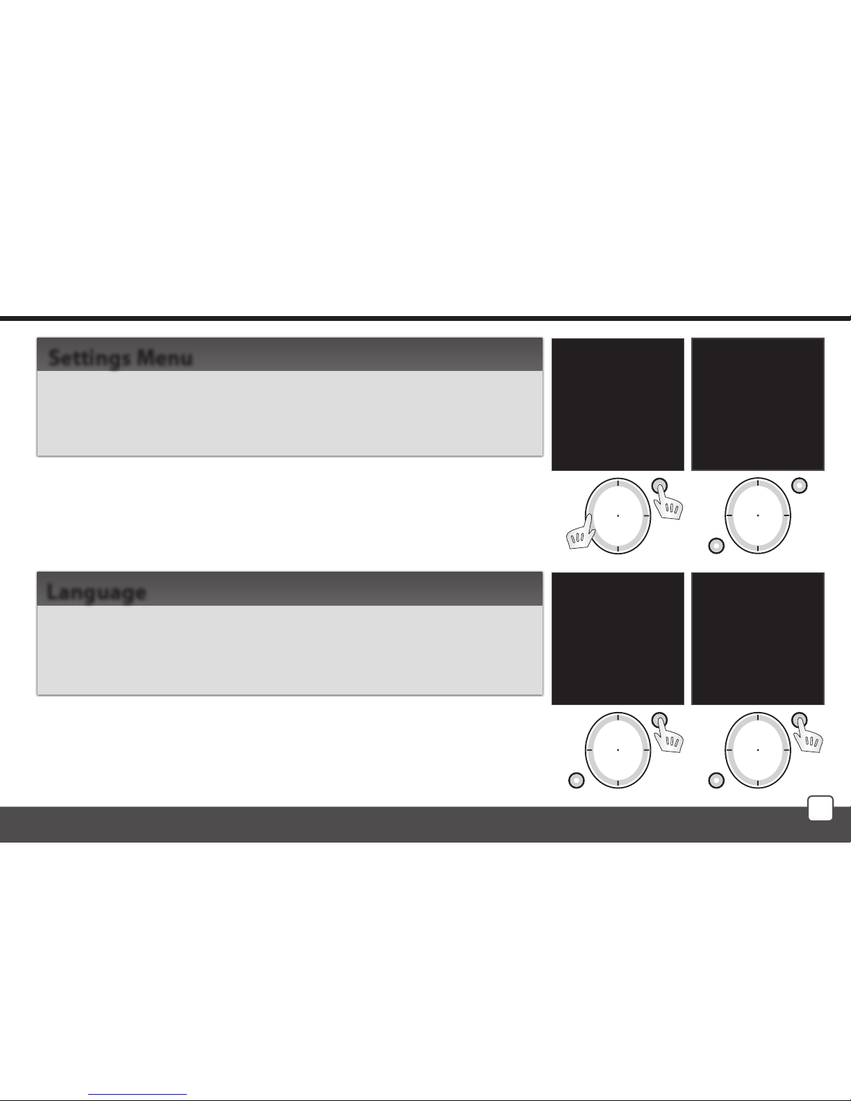
To enter the Settings Menu (Fig. 2), press the left side of the direction button together with the T1 button (Fig. 1) in the Basic
Menu.
Settings Menu
Used for language setting. Press T1 (Fig. 3) to enter the Language
Menu. Choose the requested language using the direction button
(Fig. 4). Conrm using the T1 button.
Language
mo 01.01.10 12:54
Rooms
Scenes
Favourite
EXIT SELECT
Fig. 1
Language
Date and time
Actuators
Rooms
Scenes
Favourite
Device reset
EXIT SELECT
Fig. 2
Cestina
Slovencina
English
Deutsch
Magyar
Pyccии яз.
Romana
Polski
EXIT SELECT
Fig. 4
Language
Date and time
Actuators
Rooms
Scenes
Favourite
Device reset
EXIT SELECT
Fig. 3
Page 14
14
T1
T2
T1
T2
T1
T2
Settings - Date and Time
mo 01.01.10 12:54
Hours:
00
Minutes:
00
EXIT SELECT
Fig. 3
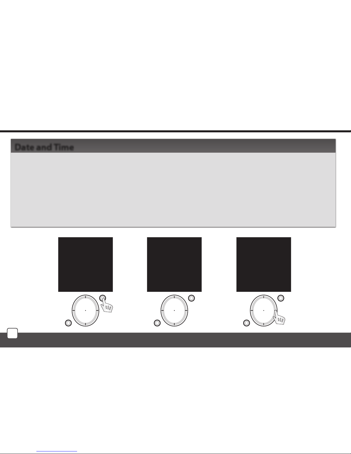
Move in the Settings menu using the direction button to select Date and time. Conrm using the T1
button (Fig. 1).
Here you can set the current time, time format (12/24), date and day of the week (Fig. 2).
- You can move in the requested direction by pressing the upper or lower part of the direction button.
- You can display a wider selection of settings by pressing the right or left side of the direction button.
- Set the value by pressing the sides of the direction button (Fig. 3).
- Save the settings by pressing T1.
Date and Time
Time:
00:00
Format:
12
Date:
01 Jan 2010
Day in week:
Monday
EXIT SAVE
Fig. 2
Language
Date and time
Actuators
Rooms
Scenes
Favourites
Device reset
EXIT SELECT
Fig. 1
Page 15
15
T1
T2
T1
T2
T1
T2
T1
T2
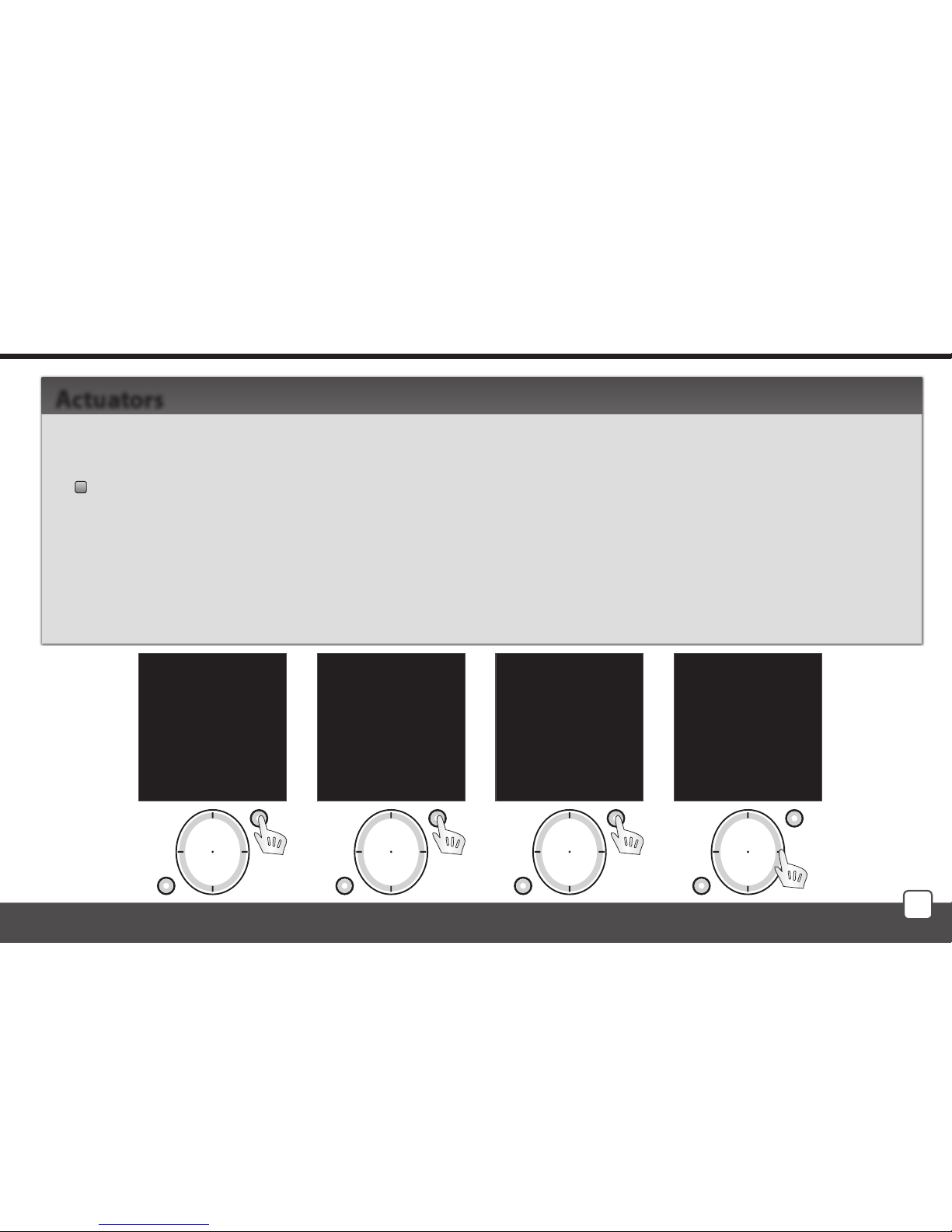
Move in the Settings Menu using the direction button to select Actuators. Press the T1 button to
display the Settings Menu (Fig. 1, 2).
Add - adding actuators to the RF Pilot Controller (Fig.2).
Use the direction button to select the actuator type which you want to use. Confirm using the
T1 button (Fig. 3).
In the following menu, enter the actuator address using the direction button (Fig. 4).
Note.: - Move in the address line by pressing the direction button in the left or right direction.
- Select characters by pressing the direction button - up and down.
Confirm using the T1 button.
Actuators
Settings - Actuators
Language
Date and time
Actuators
Rooms
Scenes
Favourite
Device reset
EXIT SELECT
Fig. 1
mo 01.01.10 12:54
Type:
RFSA-11
RFSA-6x
RFJA-12
RFDA-71
RFDA-11
RFDAC-71
EXIT SELECT
Fig. 3
mo 01.01.10 12:54
Address:
000000
0 1 2 3 4 5 6 7 8 9
A B C D E F
EXIT SELECT
Fig. 4
mo 01.01.10 12:54
Add
Assign
Rename
Range test
Control
Remove
EXIT SELECT
Fig. 2
Page 16
16
T1
T2
T1
T2
T1
T2
T1
T2
T1
T2
Settings - Actuators
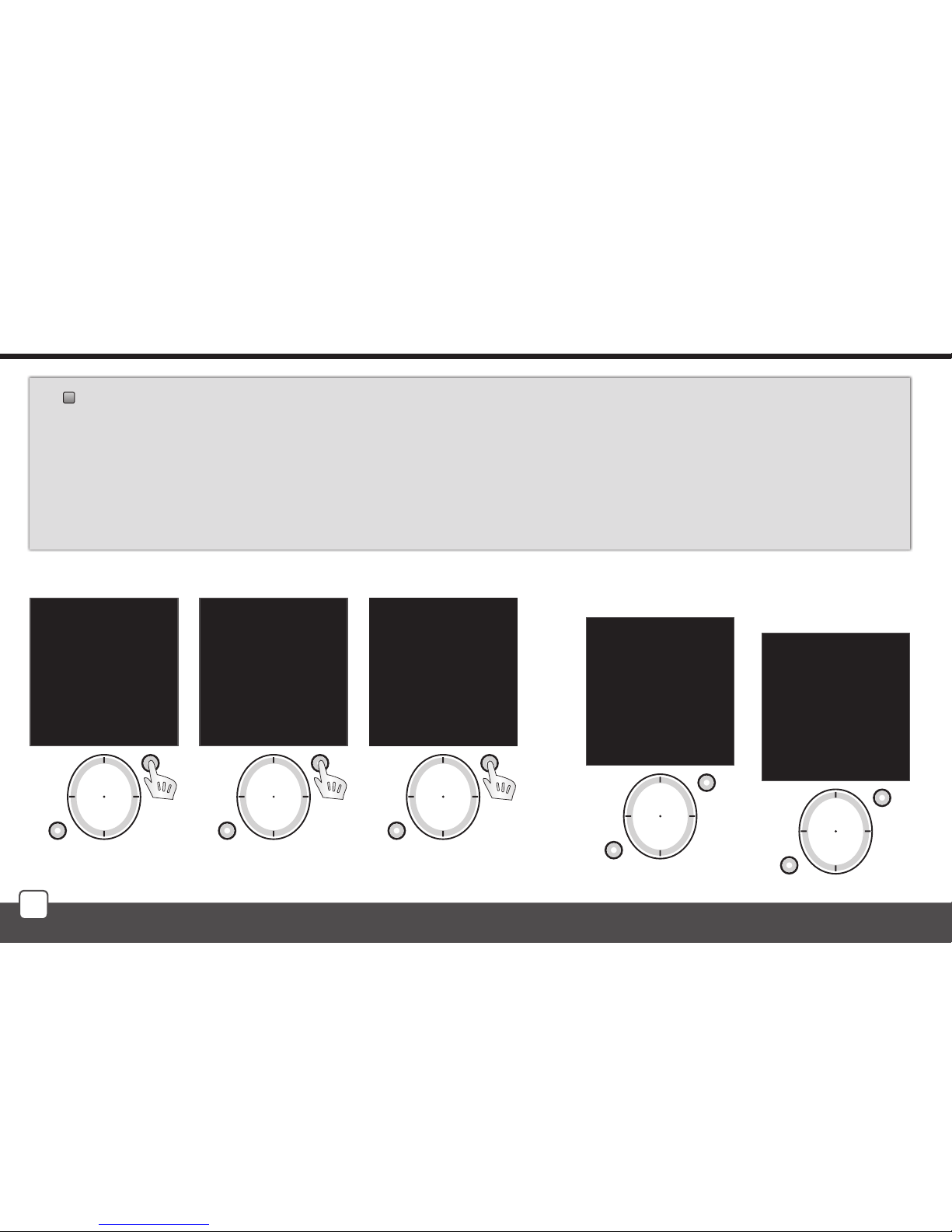
Allocate - used to allocate the added actuator to a room (Fig.1). Names of Rooms 1-10 are set
as default in the Controller.
Using the direction button select the actuator to be allocated. Confirm selection using the T1 button
(Fig. 2). After entering the next menu, using the direction button select the name of the room you
want to allocate the actuator to. Confirm using the T1 button (Fig. 3). Actuator is allocated (Fig. 4).
Note: If the name has already been allocated, a warning is displayed, see Fig. 5.
mo 01.01.10 12:54
Add
Assign
Rename
Range test
Control
Remove
EXIT SELECT
Fig. 1
Memory:
1/40
Type/address:
RFSA11/012345
Room:
Not allocated
Name:
Actuator 1
EXIT ASSIGN
Fig. 2
mo 01.01.10 12:54
Room
assigned
EXIT ALLOCATE
Fig. 4
Actuator
already used !
Fig. 5
mo 01.01.10 12:54
Room 1
Room 2
Room 3
Room 4
Room 5
Room 6
Room 7
EXIT ALLOCATE
Fig. 3
Page 17
17
T1
T2
T1
T2
T1
T2
Settings - Actuators
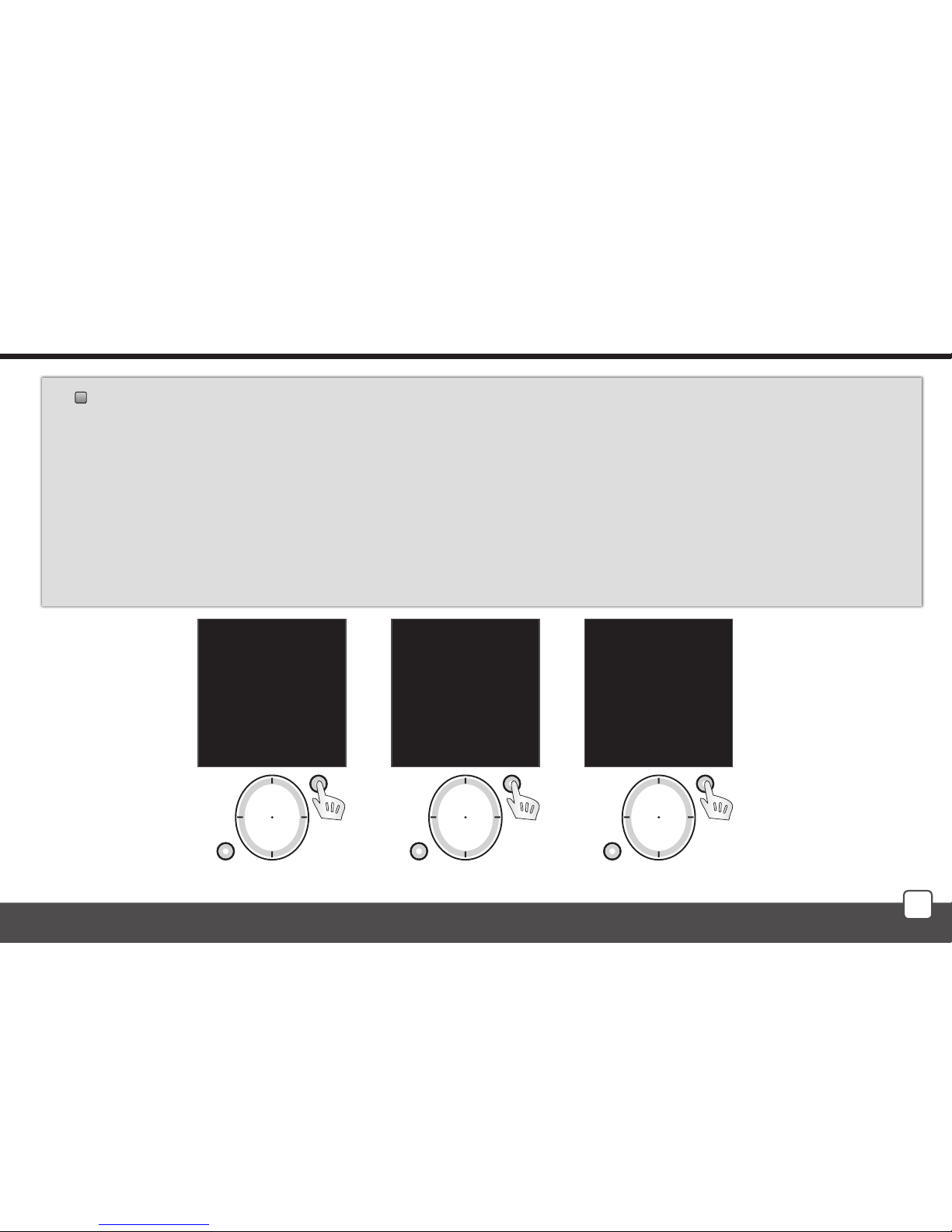
Rename - (Fig. 1) used to name the actuator, the name will be displayed in the main menu list.
The Controller automatically arranges the names of Actuator 1 - 40 in order in the Add Menu. (The
Rename function is optional.)
Using the direction button select the actuator to be renamed. Confirm using the T1 button (Fig. 2).
Choose the name of the actuator using the direction button in the following list.
Confirm using the T1 button (Fig. 3).
Note.: - Move in the actuator name line by pressing the direction button in the left or right part.
- Select characters by pressing the direction button - up and down (max. 12 characters). Press the T2 button to delete
the marked character.
mo 01.01.10 12:54
Add
Allocate
Rename
Range test
Control
Remove
EXIT SELECT
Fig. 1
Memory:
1/40
Type/address:
RFSA11/012345
Room:
Room 1
Name:
Actuator 1
EXIT RENAME
Fig. 2
Name:
Lamp
_ A B C D E F G H I J
K L M N O P Q R S T U
V W X Y Z a b c d e f
g h i j k l m n o p q
r s t u v w x y z
0 1 2 3 4 5 6 7 8 9
DELETE SAVE
Fig. 3
Page 18
18
T1
T2
T1
T2
T1
T2
T1
T2
T1
T2
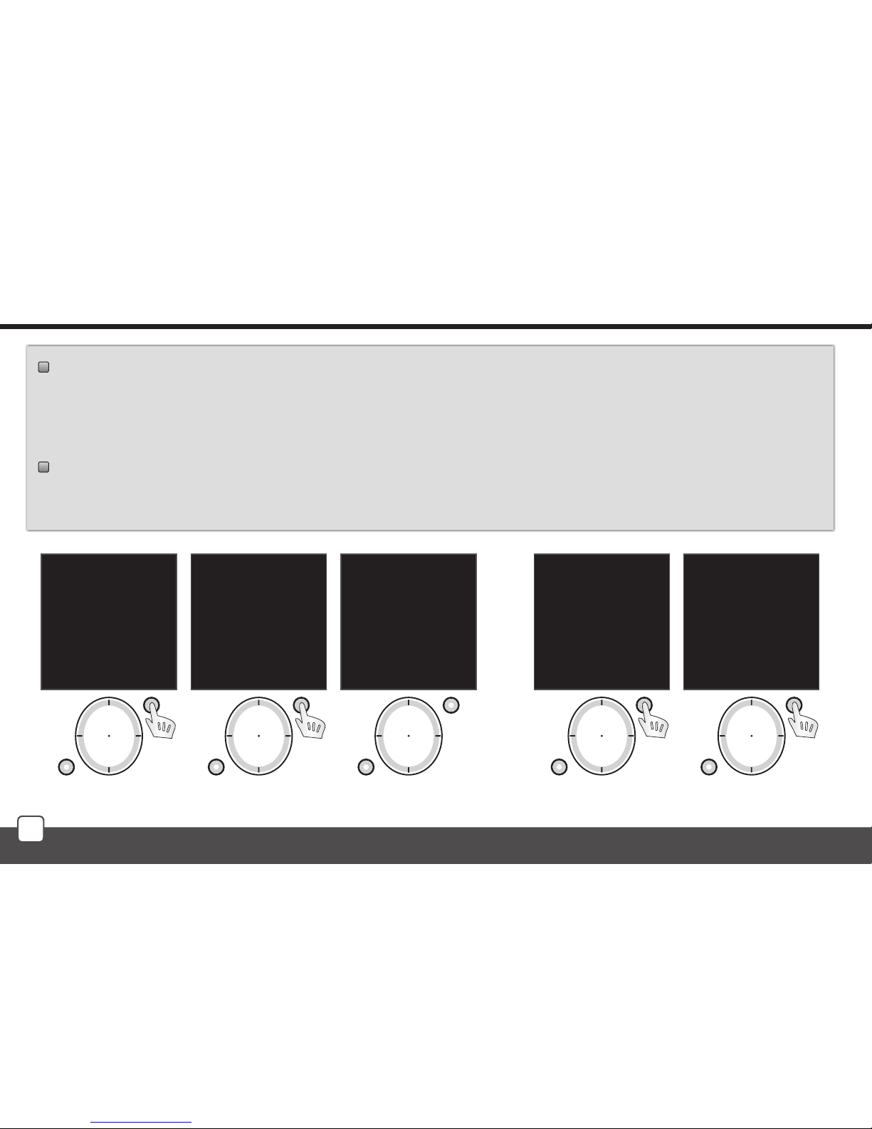
Range test - used to determine the quality of the signal between the RF Pilot and the controlled
actuator (Fig. 1). Use the direction button to select the actuator the signal of which you want
to test. Confirm using the T1 button (Fig. 2). The test result will be displayed after approx. 10s
(Fig. 3). Reach Test is an optional function.
Control - Control - serves for a quick test of actuator function (Fig. 4).
Using the direction button select the actuator to be controlled. Conrm using the T1 button (Fig. 5).
The list of functions supported by the selected actuator will be displayed.
Settings - Actuators
Memory:
2/40
Type/address:
RFSA6x/123456
Room:
Room 1
Name:
Lamp
EXIT SELECT
Fig. 5
mo 01.01.10 12:54
Add
Allocate
Rename
Range test
Control
Remove
EXIT SELECT
Fig. 4
mo 01.01.10 12:54
Actuator test:
Packets 0/10
Signal status 0%
CONTINUE
Fig. 3
Memory:
1/40
Type/address:
RFSA11/012345
Room:
Room 1
Name:
Lamp
EXIT SELECT
Fig. 2
mo 01.01.10 12:54
Add
Allocate
Rename
Range test
Control
Remove
EXIT SELECT
Fig. 1
Page 19
19
T1
T2
T1
T2
T1
T2
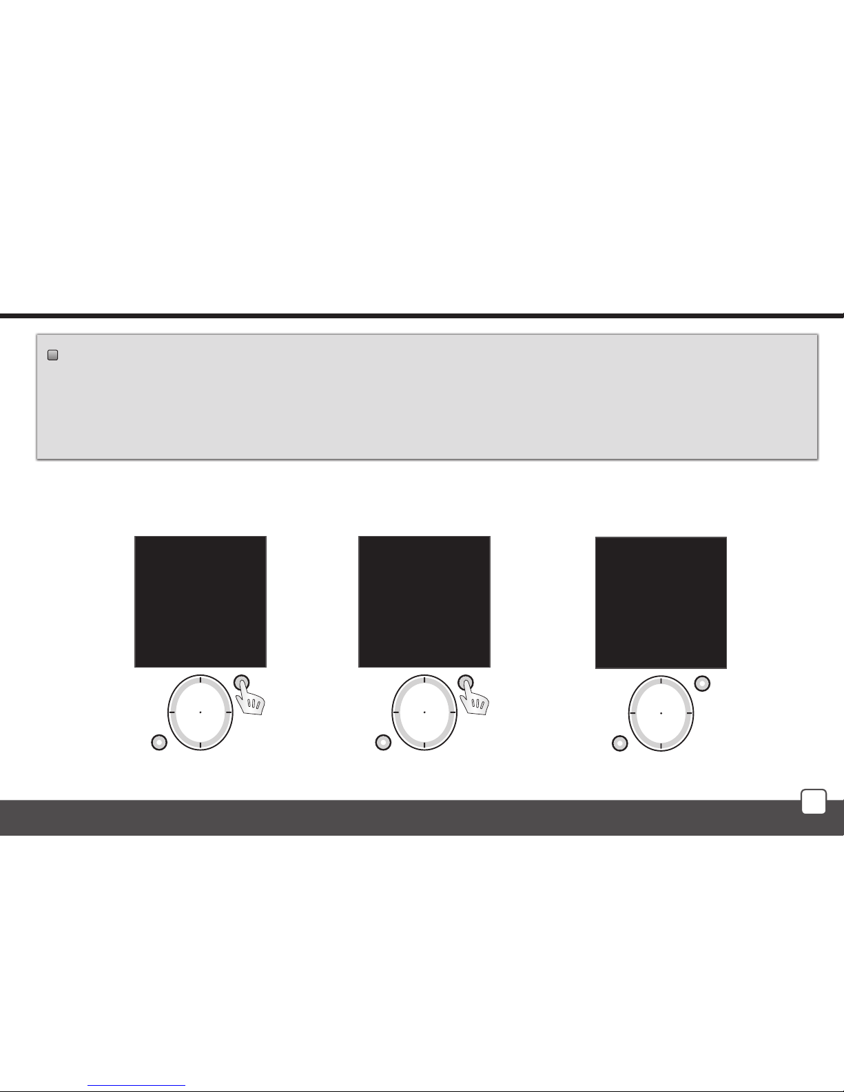
Remove - used to delete the actuator from the memory of RF Pilot (Fig. 1).
Using the direction button select the actuator to be removed.
Conrm using the T1 button (Fig. 2).
Note: If an actuator is removed from the controller memory, the relevant position in the actuator list becomes vacant (Fig. 3).
The rst vacant position in the list is used to assign the next actuator.
Settings - Actuators
mo 01.01.10 12:54
Add
Allocate
Rename
Range test
Control
Remove
EXIT SELECT
Fig. 1
Memory:
1/40
Type/address:
RFSA11/012345
Room:
Not allocated
Name:
Actuator 1-
EXIT DELETE
Fig. 2
Memory:
1/40
Type/address:
Free position
Room:
Free position
Name:
Free position
EXIT
Fig. 3
Page 20
20
T1
T2
T1
T2
T1
T2
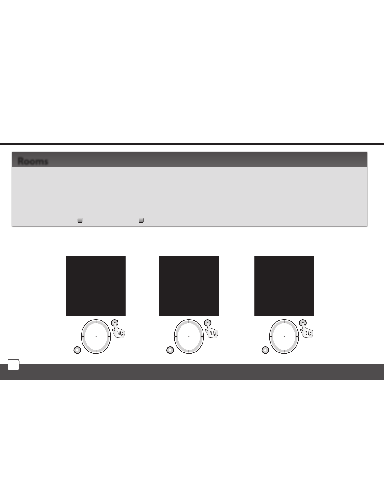
Menu Rooms is used to name the rooms, the name will be displayed in the main menu list. Move in
the Settings Menu using the direction button to select Rooms. Press T1 to enter the menu (Fig. 1).
By pressing the direction button select the Room and confirm by pressing T1 (Fig. 2). The menu is
displayed (Fig. 3):
Rename Reset
Rooms
Settings - Rooms
Language
Date and time
Actuators
Rooms
Scenes
Favourite
Device reset
EXIT SELECT
Fig. 1
mo 01.01.10 12:54
Room 1
Room 2
Room 3
Room 4
Room 5
Room 6
Room 7
EXIT SELECT
Fig. 2
mo 01.01.10 12:54
Name:
Room 1
Rename
Reset
EXIT SELECT
Fig. 3
Page 21
21
T1
T2
T1
T2
T1
T2
T1
T2
T1
T2
Settings - Rooms
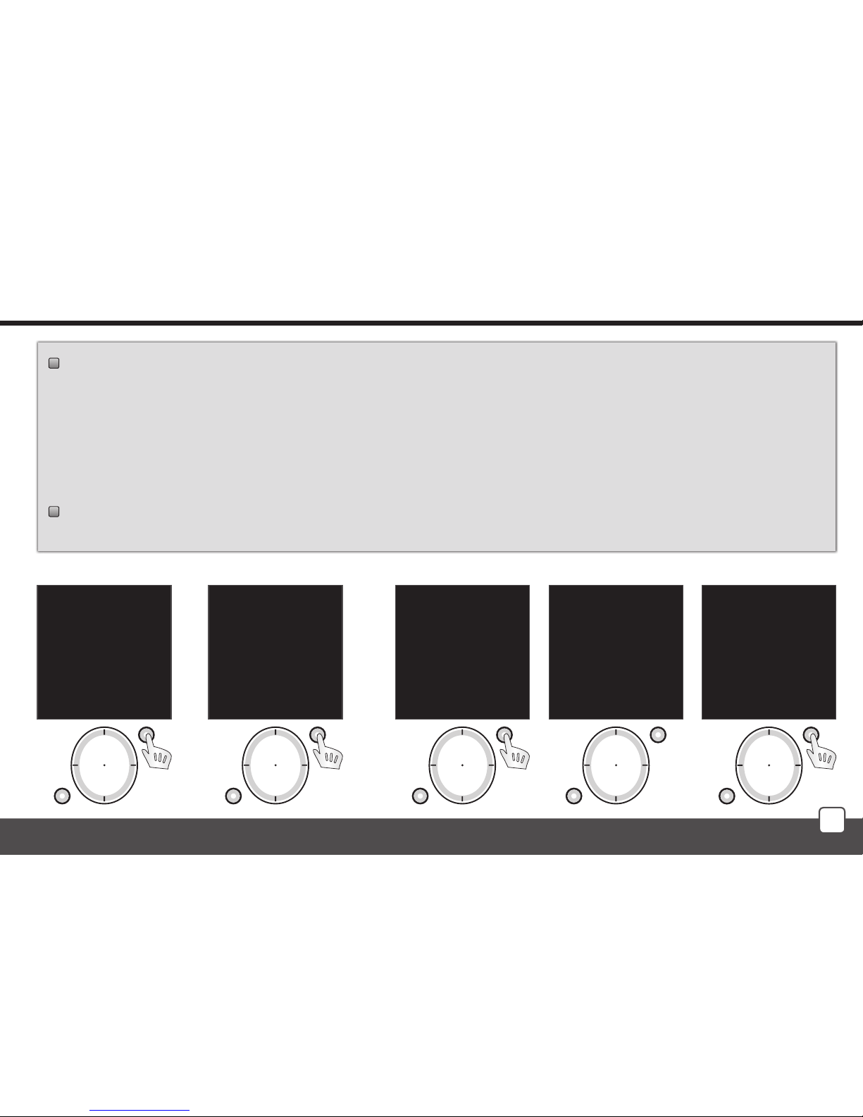
Rename - used for naming the rooms. (The Rename function is optional.)
Using the direction button select the actuator to be renamed. Confirm using the T1 button
(Fig. 1). Rename the scene using the direction button in the following menu.
Confirm using the T1 button (Fig. 2).
Note.: - Move in the room name line by pressing the direction button in the left or right direction.
- Select characters by pressing the direction button - up and down.
Reset - serves for cancelling the assignment of actuators to rooms (Fig. 3-4).
Note: The Room name will be reset to factory setting (Fig. 5).
mo 01.01.10 12:54
Name:
Room 1
Rename
Reset
EXIT SELECT
Fig. 1
Name:
Lighting
_ A B C D E F G H I J
K L M N O P Q R S T U
V W X Y Z a b c d e f
g h i j k l m n o p q
r s t u v w x y z
0 1 2 3 4 5 6 7 8 9
DELETE SAVE
Fig. 2
mo 01.01.10 12:54
Name:
Lighting
Rename
Reset
EXIT SELECT
Fig. 3
mo 01.01.10 12:54
Room
reset !
EXIT SELECT
Fig. 4
mo 01.01.10 12:54
Name:
Room 1
Rename
Reset
EXIT SELECT
Fig. 5
Page 22
22
T1
T2
T1
T2
T1
T2
Settings - Scenes
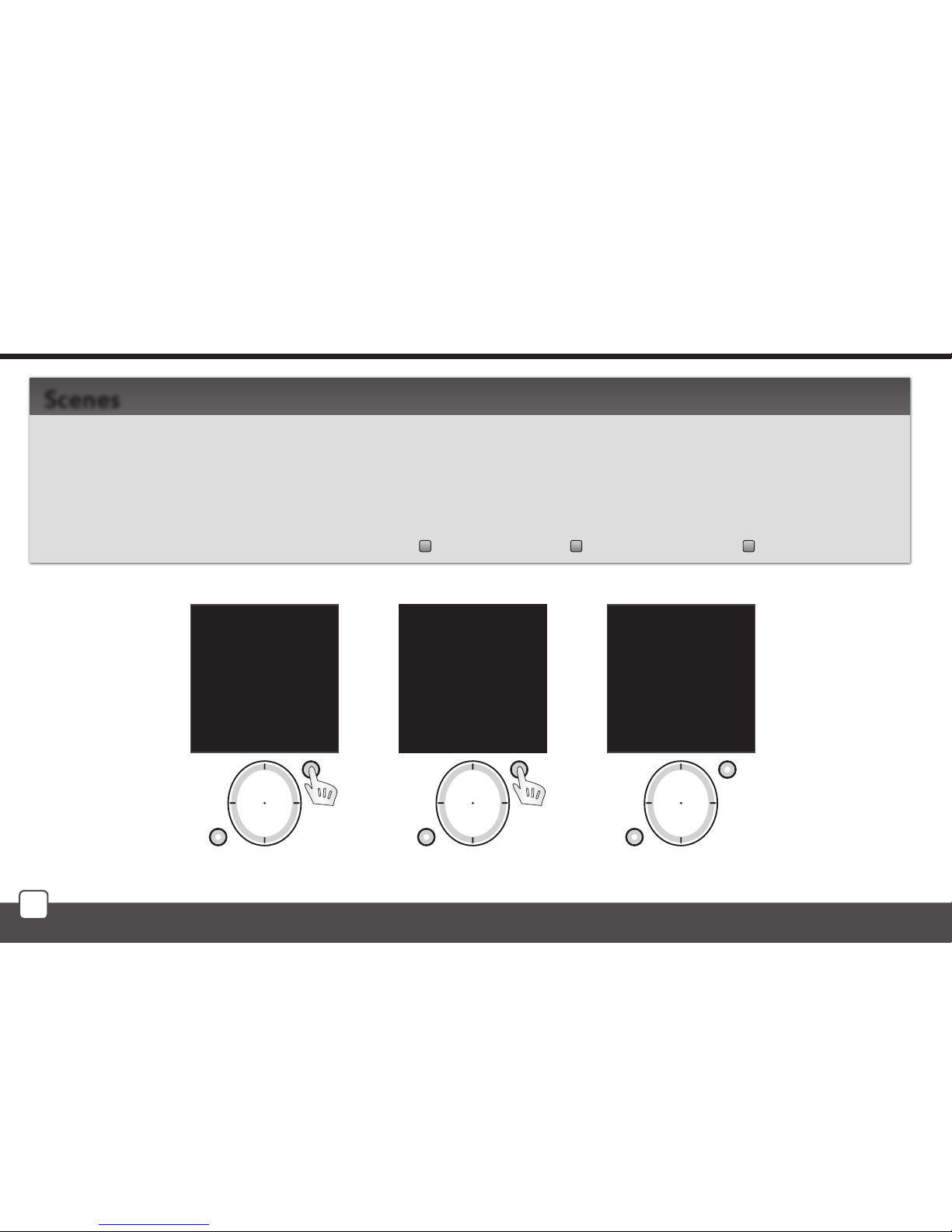
Settings Menu - Scenes serves to set the control of multiple actuators using a single press.
Move in the Settings Menu using the direction button to select Scenes. Press T1 to enter the menu
(Fig. 1).
Using the direction button select the name of the Scene. Confirm using the T1 button (Fig. 2). The
following options will be displayed (Fig. 3): Rename Commands Restart
Scenes
Language
Date and time
Actuators
Rooms
Scenes
Favourite
Device reset
EXIT SELECT
Fig. 1
mo 01.01.10 12:54
Scene 1
Scene 2
Scene 3
Scene 4
Scene 5
Scene 6
Scene 7
EXIT SELECT
Fig. 2
mo 01.01.10 12:54
Name:
Scene 1
Rename
Commands
Restart
BACK PROCEED
Fig. 3
Page 23
23
T1
T2
T1
T2
T1
T2
T1
T2
T1
T2
Settings - Scenes
Rename - used to name a scene, the name will be displayed in the main menu list.
(The Rename function is optional.) Fig. 1.
Rename the scene using the direction button in the following list.
Confirm using the T1 button (Fig. 2).
Note.: - Move in the room name line by pressing the direction button in the left or right direction.
- Select characters by pressing the direction button - up and down.
Commands - (Fig. 3) you can assign an actuator (Fig. 5) from a selected room (Fig. 4) and define
its function that will be executed when the scene is activated.
Note.: Up to 10 commands can be allocated to each scene.
mo 01.01.10 12:54
Name:
Scene 1
Rename
Commands
Reset
BACK PROCEED
Fig. 1
Name:
Kitchen
_ A B C D E F G H I J
K L M N O P Q R S T U
V W X Y Z a b c d e f
g h i j k l m n o p q
r s t u v w x y z
0 1 2 3 4 5 6 7 8 9
DELETE SAVE
Fig. 2
mo 01.01.10 12:54
Name:
Kitchen
Rename
Commands
Reset
BACK PROCEED
Fig. 3
mo 01.01.10 12:54
Lighting
Room 2
Room 3
Room 4
Room 5
Room 6
Room 7
EXIT SELECT
Fig. 4
mo 01.01.10 12:54
RFSA-11B
RFDA-71B
EXIT SELECT
Fig. 5
Page 24
24
T1
T2
T1
T2
T1
T2
Settings - Scenes
Reset - cancels the assignment of actuators to scenes (Fig. 1-2).
Note: The Scene name will be reset to factory setting (Fig. 3).
mo 01.01.10 12:54
Name:
Kitchen
Rename
Commands
Reset
BACK PROCEED
Fig. 1
mo 01.01.10 12:54
Scene
reset!
BACK PROCEED
Fig. 2
mo 01.01.10 12:54
Name:
Scene 1
Rename
Commands
Reset
BACK PROCEED
Page 25
25
T1
T2
T1
T2
T1
T2
Settings - Favourite
Menu Settings - Favourite is used to include ten most frequently used devices (actuators / scenes)
directly in the main screen as a shortcut for quick control without further search.
Move in the Settings Menu using the direction button to select Favourite. Press T1 to enter the menu
(Fig. 1).
In the Favourite menu select the time you want to edit. Confirm using the T1 button (Fig. 2). The
menu is displayed (Fig. 3): Assign Cancel
Favourite
mo 01.01.10 12:54
Favourite 1
Favourite 2
Favourite 3
Favourite 4
Favourite 5
Favourite 6
Favourite 7
BACK PROCEED
Fig. 2
Language
Date and time
Actuators
Rooms
Scenes
Favourite
Device reset
EXIT SELECT
Fig. 1
mo 01.01.10 12:54
Name:
Favourite 1
Assign
Cancel
BACK PROCEED
Fig. 3
Page 26
26
T1
T2
T1
T2
T1
T2
T1
T2
T1
T2
T1
T2
T1
T2
T1
T2
Settings - Favourite
Include - used to include an actuator or scene:
- Actuator: you can include a requested
actuator from a selected room (Fig. 1-3).
- the actuator name will be displayed.
- Actuator with function: you can
include a requested actuator from a
selected room)and define its function
(Fig. 4-7) - the name of the actuator / F
will be displayed.
mo 01.01.10 12:54
RFSA-11B
RFDA-71B
EXIT SELECT
Fig. 3
mo 01.01.10 12:54
Lighting
Room 2
Room 3
Room 4
Room 5
Room 6
Room 7
EXIT SELECT
Fig. 2
mo 01.01.10 12:54
Select type:
Actuator
Actuator with func.
Scene
BACK PROCEED
Fig. 1
mo 01.01.10 12:54
Turn on
Turn o
EXIT ASSIGN
Fig. 7
mo 01.01.10 12:54
RFSA-11B
RFDA-71B
EXIT SELECT
Fig. 6
mo 01.01.10 12:54
Lighting
Room 2
Room 3
Room 4
Room 5
Room 6
Room 7
BACK PROCEED
Fig. 5
mo 01.01.10 12:54
Select type:
Actuator
Actuator with func.
Scene
BACK PROCEED
Fig. 4
po 01.01.10 12:54
Lighting/F
Favourite 2
Favourite 3
Favourite 4
Favourite 5
Favourite 6
Favourite 7
BACK PROCEED
Fig. 5
Page 27
27
T1
T2
T1
T2
T1
T2
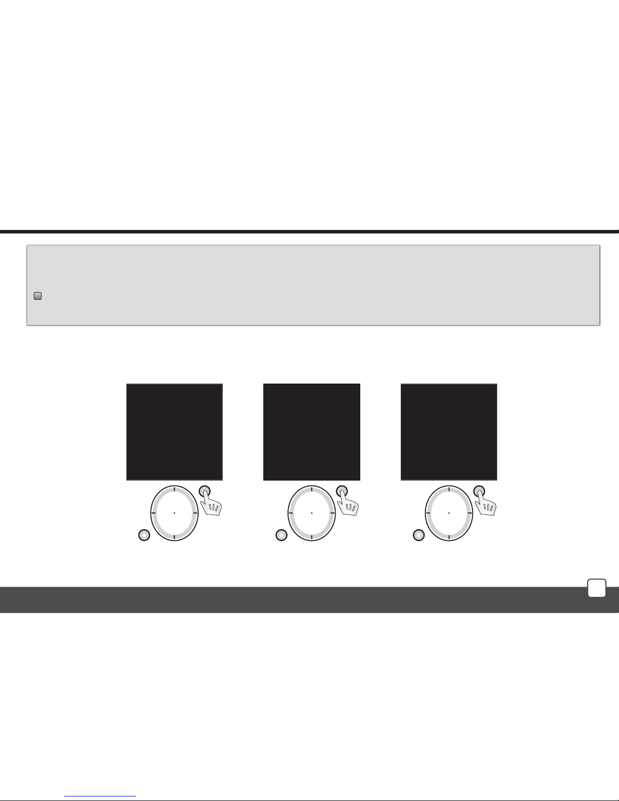
- Scene: you can include the requested scene to Favourites (multiple actuators are controlled by
a single press), Fig. 1-2
Cancel - used to delete actuators / scenes.
The Favourite name will be reset to factory setting (Fig 3).
Settings - Favourite
mo 01.01.10 12:54
Name:
Lighting
Assign
Cancel
BACK PROCEED
Fig. 3
mo 01.01.10 12:54
Select type:
Actuator
Actuator with func.
Scene
BACK PROCEED
Fig. 1
mo 01.01.10 12:54
Scene 1
Scene 2
Scene 3
Scene 4
Scene 5
Scene 6
Scene 7
EXIT SELECT
Fig. 2
Page 28
28
T1
T2
T1
T2
T1
T2
T1
T2
Settings - Device Reset
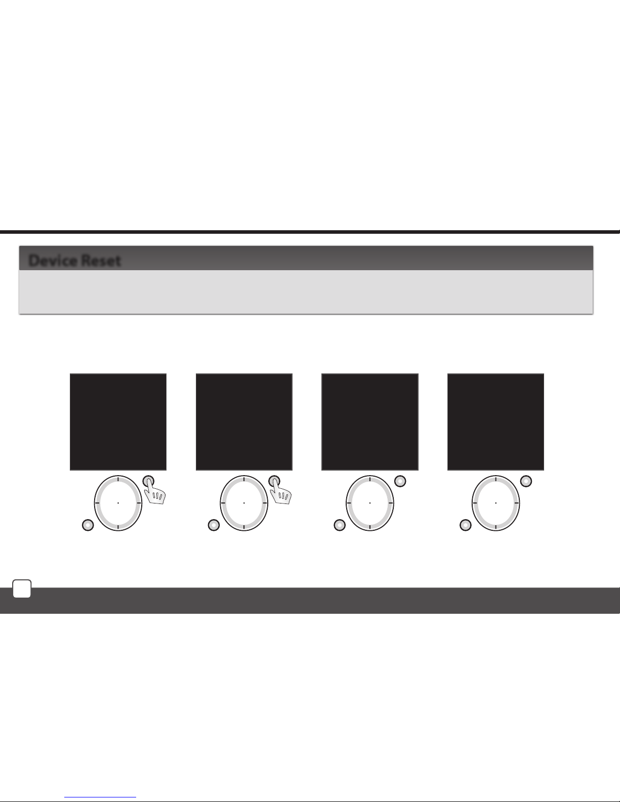
Reset of the device is used to delete all settings (Fig. 1-2). The number of the firmware is displayed,
the memory is Formatted and the factory setting is restored (Fig. 3-4).
Device Reset
Language
Date and time
Actuators
Rooms
Scenes
Favourite
Device reset
EXIT SELECT
Fig. 1
mo 01.01.10 12:54
Really reset?
No
Yes
EXIT SELECT
Fig. 2
RF Pilot
Firmware 1.05
Fig. 3
Formatting
memory...
Fig. 4
Page 29
29
T1
T2
T1
T2
T1
T2
T1
T2
Initial Screen - Quick Control
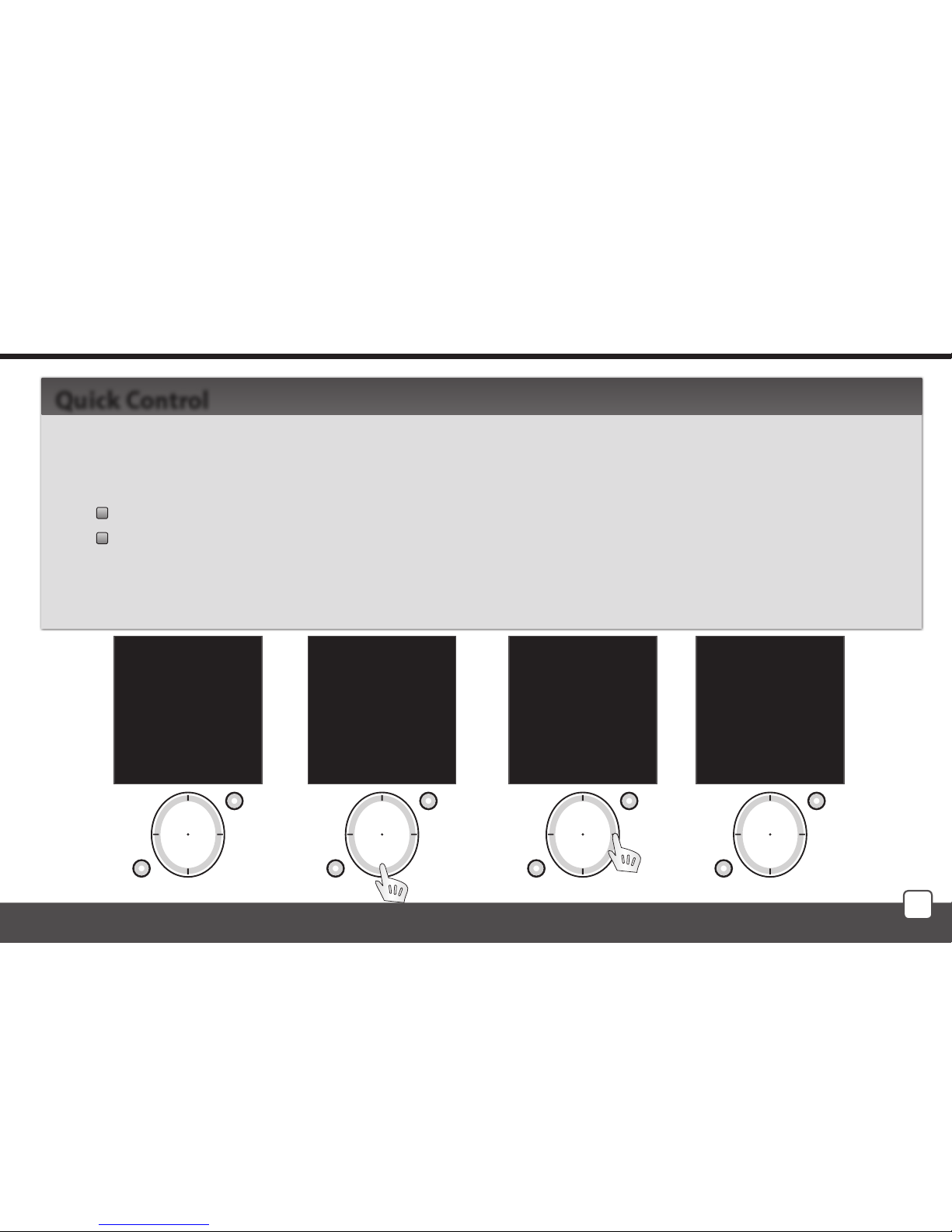
Activate RF Pilot from sleep by pressing any button. Press any button briefly to display the Initial
Screen (Fig. 1). Directly from the Initial Screen you can control the preset actuators and devices.
Using the direction button (up / down - Fig. 2) select the requested Favourite.
Activate the allocated command using the direction button (Fig. 3-4).
By pressing the left side of the direction button the activated command is switched off
(stop function for the roller blind/shutter actuator).
- green symbol - command accepted and executed by the actuator (Fig. 3)
- red symbol - Error (Fig. 4) - see page 37
Quick Control
mo 01.01.10 12:54
Favourite 1
Favourite 2
Favourite 3
Lamps
Favourite 5
Favourite 6
Favourite 7
Temp.: 23C MENU
Fig. 1
mo 01.01.10 12:54
Favourite 1
Favourite 2
Favourite 3
Lamps
Favourite 5
Favourite 6
Favourite 7
Temp.: 23C MENU
Fig. 2
mo 01.01.10 12:54
Favourite 1
Favourite 2
Favourite 3
Lamps
Favourite 5
Favourite 6
Favourite 7
Temp.: 23C MENU
Fig. 3
mo 01.01.10 12:54
Favourite 1
Favourite 2
Favourite 3
Lamps ×
Favourite 5
Favourite 6
Favourite 7
Temp.: 23C MENU
Fig. 4
Page 30
30
Quick Control
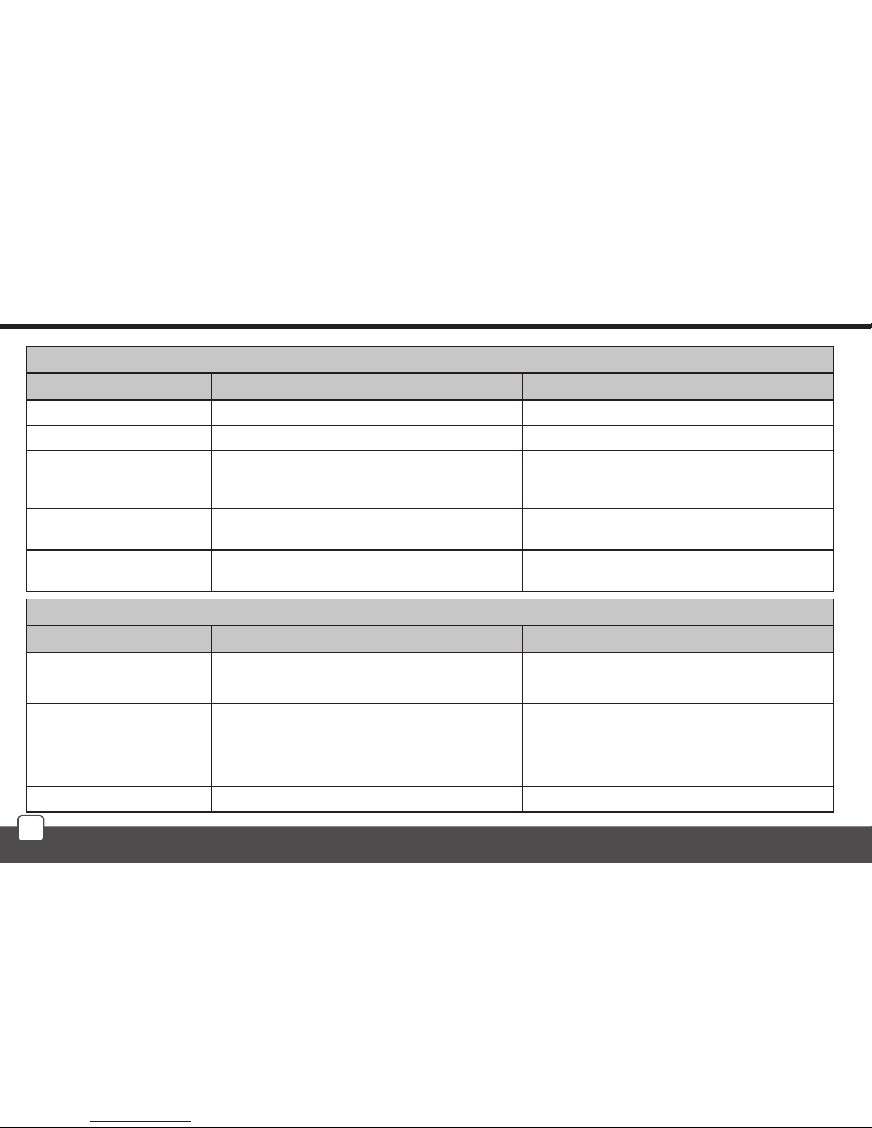
Controlling the assigned actuator (without function)
Actuator Pressing the directional button left Pressing the directional button right
RFSA-11 Switch Off. Switch On.
RFSA-6x Switch Off. Switch On.
RFJA-12 Simulation of the button on the key-chain - tilting
the roll-up blinds. Press and hold to send the roll-up
blinds up.
Simulation of the button on the Key-chain - tilting
the roll-up blinds. Press and hold to send the roll-up
blinds down.
RFDA-11 Switch Off. Each pressing of the button will increase the bright-
ness by 10% (to max. 100%).
RFDA-71 Switch Off. Each pressing of the button will increase the bright-
ness by 10% (to max. 100%).
Controlling the assigned button with function
Actuator Pressing the directional button left Pressing the directional button right
RFSA-11 Switch Off. Activates the set function.
RFSA-6x Switch Off. Activates the set function.
RFJA-12 By pressing once stop the motion of the roll-up
blinds. By pressing again, set the roll-up blinds into
motion in the opposite direction. Activates the set function.
RFDA-11 Switch Off. Activates the set function.
RFDA-71 Switch Off. Activates the set function.
Page 31
31
T1
T2
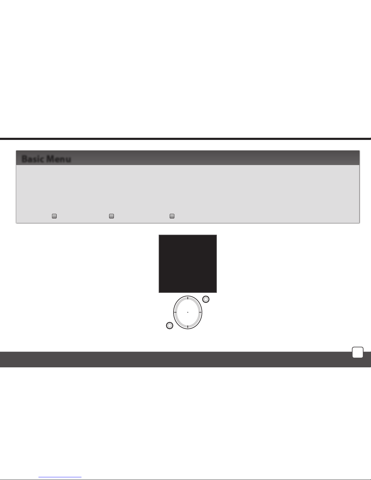
Basic Menu - Control
From the sleep mode you can enter the Basic Menu (Fig.1) in two ways:
- Press any button briefly to display the Initial Screen. By pressing T1 the Basic Menu will be
displayed.
- By pressing and holding T1 longer than 2 s you can directly enter the Basic Menu:
Rooms Scenes Favourite
Basic Menu
mo 01.01.10 12:54
Rooms
Scenes
Favourite
EXIT SELECT
Fig. 1
Page 32
32
T1
T2
T1
T2
T1
T2
T1
T2
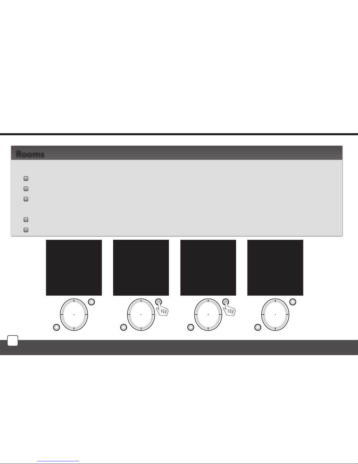
Menu Rooms is used to control the allocated Actuators.
Press T1 to enter the menu (the names of Room 1-10 are set as default).
Select the requested Room using the direction button (up / down).
By pressing T1 (Fig. 2) enter the list of Actuators allocated to a particular Room (the names of
Actuator 1-10 are set as default).
Select the requested Actuator that you want to control using the direction button (up / down).
Using T1 (Fig. 3) enter the list of functions allocated to a particular actuator (Fig. 4).
Rooms
Control - Rooms
mo 01.01.10 12:54
Rooms
Scenes
Favourite
EXIT SELECT
Fig. 1
mo 01.01.10 12:54
Room 1
Room 2
Room 3
Room 4
Room 5
Room 6
Room 7
EXIT SELECT
Fig. 2
mo 01.01.10 12:54
Actuator 1
Actuator 2
Actuator 3
BACK PROCEED
Fig. 3
mo 01.01.10 12:54
Switch On
Switch O
Brigh.: 0%
Slightly On
Slightly O
Setting
BACK PROCEED
Fig. 4
Page 33
33
T1
T2
T1
T2
Switching Actuator Functions
RFSA-11 RFSA-6x Description
Turn On Turn On Actuator switched On
Turn O Turn O Actuator switched O
Button Actuator contact On when Controller button pressed
Impulse Switches the relay output to the opposite position
Delay On Switched On with delay
Delay O Switched O with delay
Setting Time setting of delay for switch On / O within the range of 2s - 60min.
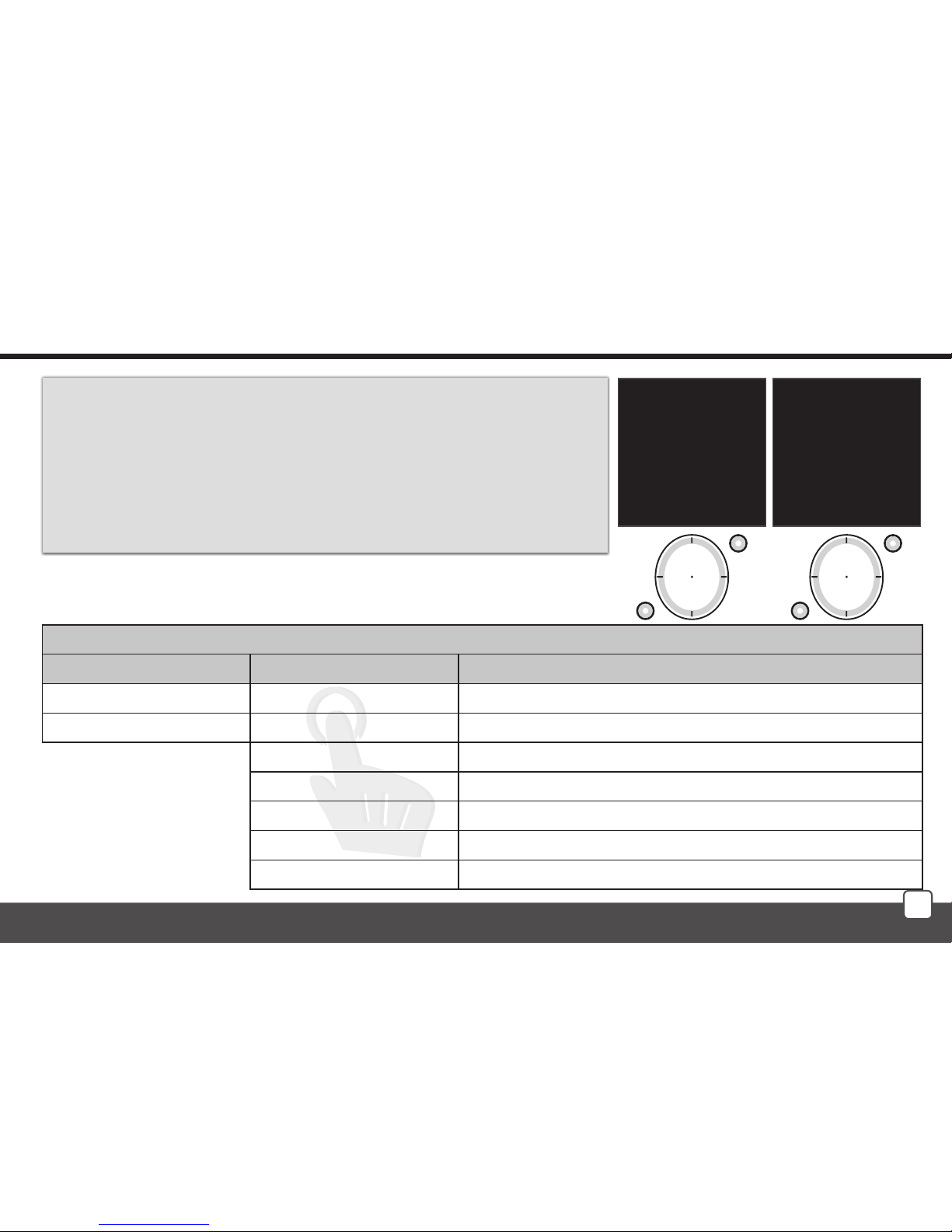
Control - Rooms / Actuator Function
Select the requested actuator function using the direction
button (up / down). Send the command to execute the selected
function by pressing T1.
- green symbol - command accepted and executed by the
actuator (Fig. 1).
- red symbol - Error (Fig. 2) - see page 37.
mo 01.01.10 12:54
Switch on
Switch O
Brightness: 0%
Gradual switch ON
Gradual switch OFF
Settings
BACK PROCEED
Fig.1
mo 01.01.10 12:54
Switch On ×
Switch O
Brightness: 0%
Gradual switch ON
Gradual switch OFF
Settings
BACK PROCEED
Fig. 2
Page 34
34
Dimming Actuator Functions
RFDA-11 RFDA-71 Description
Switch On Turn On Actuator switched On
Switch O Turn O Actuator switched O
Brightness 0% Brightness 0% Brightness setting within the range 0-100% (10% steps)
Slightly On Gradually switches On during a preset time
Slightly O Gradually switches O during a preset time
Setting Setting the time of the gradual switch On / O within the range of
2s - 30min.
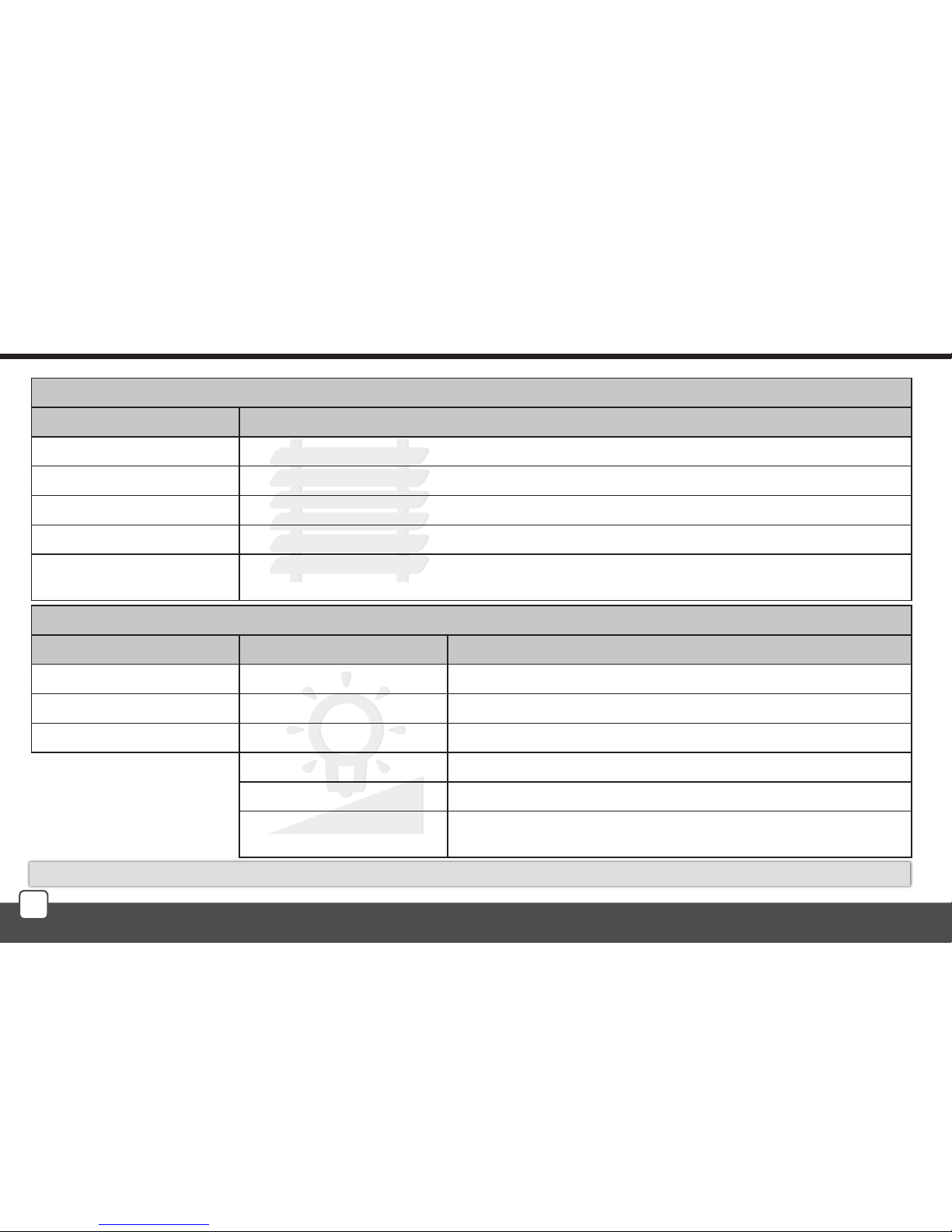
Control - Actuator Function
Roller Blind/Shutter Actuator Functions
RFJA-12 Description
Up Device moves up to end position
Down Device moves down to end position
Turn up Rolling the blinds/shutters up in gradual steps using short impulses
Turn down Rolling the blinds/shutters down in gradual steps using short impulses
Setting Setting the travel time of the device. Measure the travel time from one end position to the other
end position. Set the time data + 2s in the Controller. Range 2s - 240s.
Wait approx. 1s between individual button presses.
Page 35
35
T1
T2
T1
T2
T1
T2
T1
T2
RFSA-6x
RFJA-12
RFDA-71
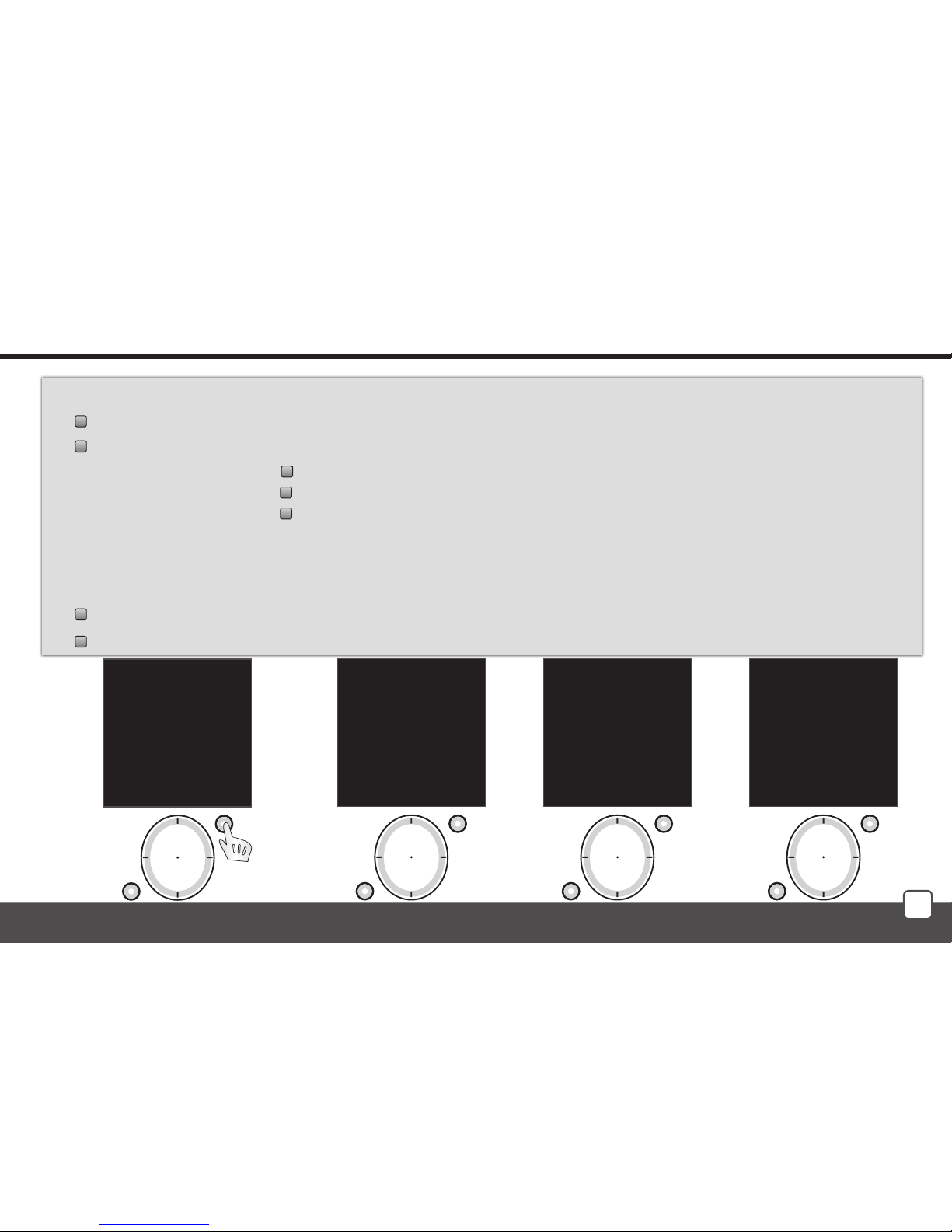
The setting serves to define time for each actuator. (Fig. 1).
Select the requested data for editing using the direction button (up / down).
You can set using the direction button (right/left):
- in the first line for RFSA-6x - delayed switch On/Off (Fig. 2)
for RFJA-12 - up / down (Fig. 3)
for RFDA-71 - gradual switch Off / On (Fig. 4)
- time can be set in the second line
- time units - s/min can be set in the third line (not in the case of RFJA-12)
By pressing T1 save the setting into memory and send a setting command to the actuator.
The value has been saved - the actuator has accepted and saved the command.
Communication error - please repeat your command. - see page 37.
Control - Rooms
mo 01.01.10 12:54
Switch On
Switch O
Brigh.: 0%
Slightly On
Slightly O
Setting
BACK PROCEED
Fig. 1
mo 01.01.10 12:54
Delay:
Delay ON
Time: 2 sec
Seconds
EXIT SAVE
Fig. 2
mo 01.01.10 12:54
Duration of nish:
Up
Time: 2 sec
EXIT SAVE
Fig. 3
mo 01.01.10 12:54
Delay:
Slightly ON
Time: 2 sec
Seconds
EXIT SAVE
Fig. 4
Page 36
36
T1
T2
T1
T2
T1
T2
T1
T2
T1
T2
Control - Scenes
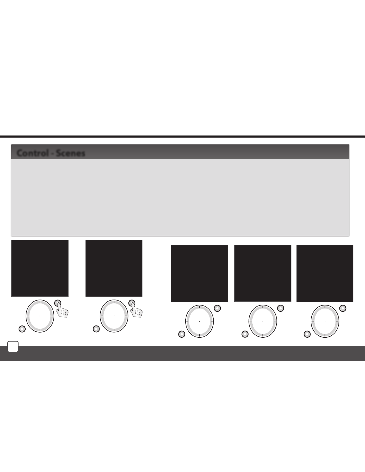
Menu Scenes is used to control the allocated commands.
Menu Scenes is selected using the direction button. Press T1 (Fig. 1) to confirm (the names of Scenes
1-10 are set as default). Select the requested Scenes using the direction button (up / down). Send a
command to execute the commands by pressing T1 (Fig. 2).
- green symbol - command accepted and executed by all actuators (Fig. 3).
- orange symbol - error (Fig. 4) - see p. 37.
- red symbol - Error (Fig. 5) - see p. 37.
Control - Scenes
mo 01.01.10 12:54
Rooms
Scenes
Favourite
EXIT SELECT
Fig. 1
mo 01.01.10 12:54
Processing
EXIT SELECT
Fig. 3
Fig. 2
mo 01.01.10 12:54
Processing ×
EXIT SELECT
Fig. 5
mo 01.01.10 12:54
Scene 1
Scene 2
Scene 3
Scene 4
Scene 5
Scene 6
Scene 7
EXIT SELECT
mo 01.01.10 12:54
Processing
EXIT SELECT
Fig. 4
Page 37
37
T1
T2
T1
T2
Control - Favourite
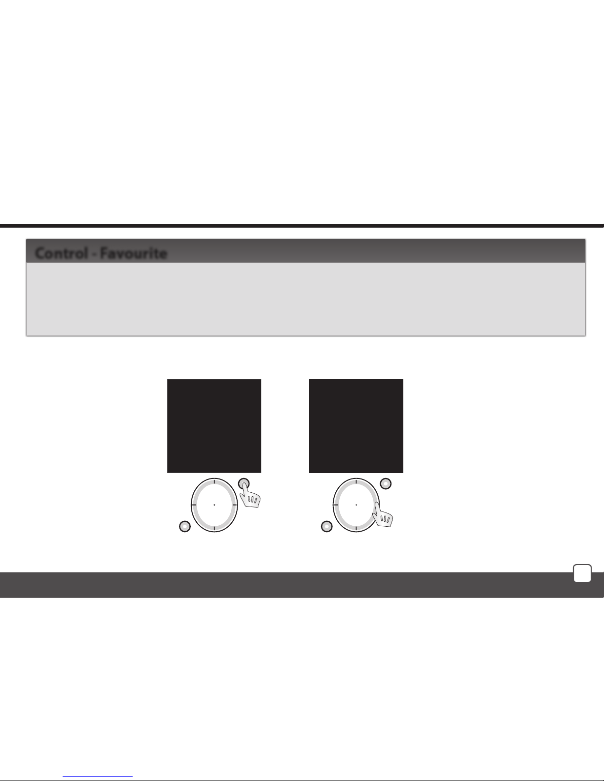
Menu Favourite is used to control the allocated Actuators or Scenes.
Menu Favourite is selected using the direction button. Press T1 (Fig. 1) to conrm (names Favourite 1-10
are set as default).
Menu Favourite is controlled in the same manner as Quick Control (See page 29).
Control - Favourite
mo 01.01.10 12:54
Rooms
Scenes
Favourite
EXIT SELECT
Fig. 1
mo 01.01.10 12:54
Lamps
Favourite 2
Favourite 3
Favourite 4
Favourite 5
Favourite 6
Favourite 7
Temp.: 23C MENU
Fig. 2
Page 38
38
What to do when ...
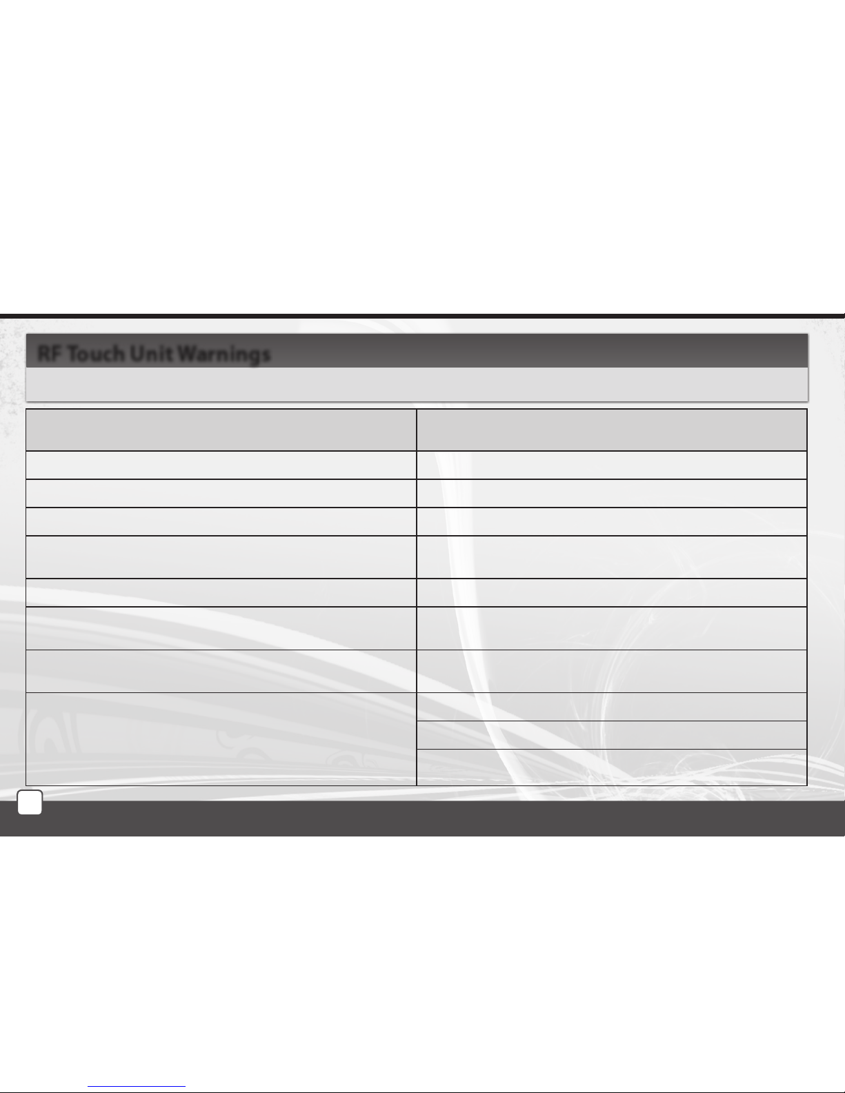
Warning is displayed in case of incorrect entry.
RF Touch Unit Warnings
warning cause / troubleshooting
Rooms / Scenes / Favourite
a fixed number of places - 10 - is set for each section
Memory full! (when adding actors)
No more than 40 actuators may be entered
The actuator has already been used.
the actuator has already been assigned to a room
Low battery indicator on Battery level must be sucient to ensure reliable communicati-
on with actuators, change batteries
Communication error!
the actuator has not accepted the command, please repeat
- orange symbol - error (when controlling scenes)
some of the actuators has not confirmed executing the
command, please repeat the command
- red symbol - error
the actuator(s) has/have not confirmed executing the command, please repeat the command
If the error persists:
- The actuator has accepted and executed the command, RF
Pilot has not detected any execution feedback signal
- A part of the actuators have accepted and executed the
command (when controlling Scenes)
Low battery
The controller is too far from the actuator(s)
Always check command execution
Page 39
39
Universal information
The displayed temperature is for information only and may be affected by the placement of the controller near heat sources, windows, prolonged
holding in hand, etc.
Rename Actuators (Rooms, Scenes) - the min. length of the name is 1 character, the max. length is 12 characters. Upon deleting the whole name
(by the T2 button) and confirming (by the T1 button), the factory setting is restored (Actuator x, Room x, Scene x).
More Actuators (Rooms, Scenes) may have the same name.
Actuators (Rooms, Scenes, Favourite) are not sorted alphabetically, but their order is determined by their position in the controller memory.
If an Actuator is removed from the controller memory, its position in the actuator list becomes vacant. The first vacant position in the list is used
to assign the next actuator.
Page 40
40
Important information
Cleaning and maintenance
• Do not immerse the Remote Controller or its parts into water or any other liquid! Prevent any liquid from entering into the Remote Controller. The device
would be damaged.
• Clean the surface using a dry cloth. Do not use aggressive cleaning products or abrasives as these could damage the Controller.
Adhere to the following instructions for battery use:
• Check the batteries regularly. Leaking batteries can damage the device.
• If you do not use your Remote Controller for a long time, remove the batteries.
• Always replace both the batteries at the same time, do not mix battery types.
• When inserting the batteries, always check their polarity as displayed in the battery compartment.
Device damage!
• Protect the product from moisture. Use the device in dry rooms only, not outdoors or near liquids. Ensure that the device does not become wet or moist
or otherwise damaged during use.
• Do not operate or leave the device in hot environment, do not expose it to direct sunlight.
• Do not place re sources such as candles near the device.
Page 41
41
Important information
Disposal:
Do not dispose of the device together with common household waste. All packaging materials should be disposed of in accordance with environmental
regulations.
Batteries/accumulators
• Batteries/accumulators must never be disposed of together with household waste. They may contain poisonous substances harmful to the environment.
Therefore the batteries/accumulators must always be disposed of in accordance with applicable regulations.
• Each consumer is obligated by law to dispose of the batteries and accumulators at a local collecting point. This obligation ensures that the batteries /
accumulators will be disposed of in accordance with environmental regulations.
Page 42
42
1.
2.
3.
4.
5.
6.
7.
8.
9.
10.
11.
12.
13.
14.
15.
16.
17.
18.
19.
20.
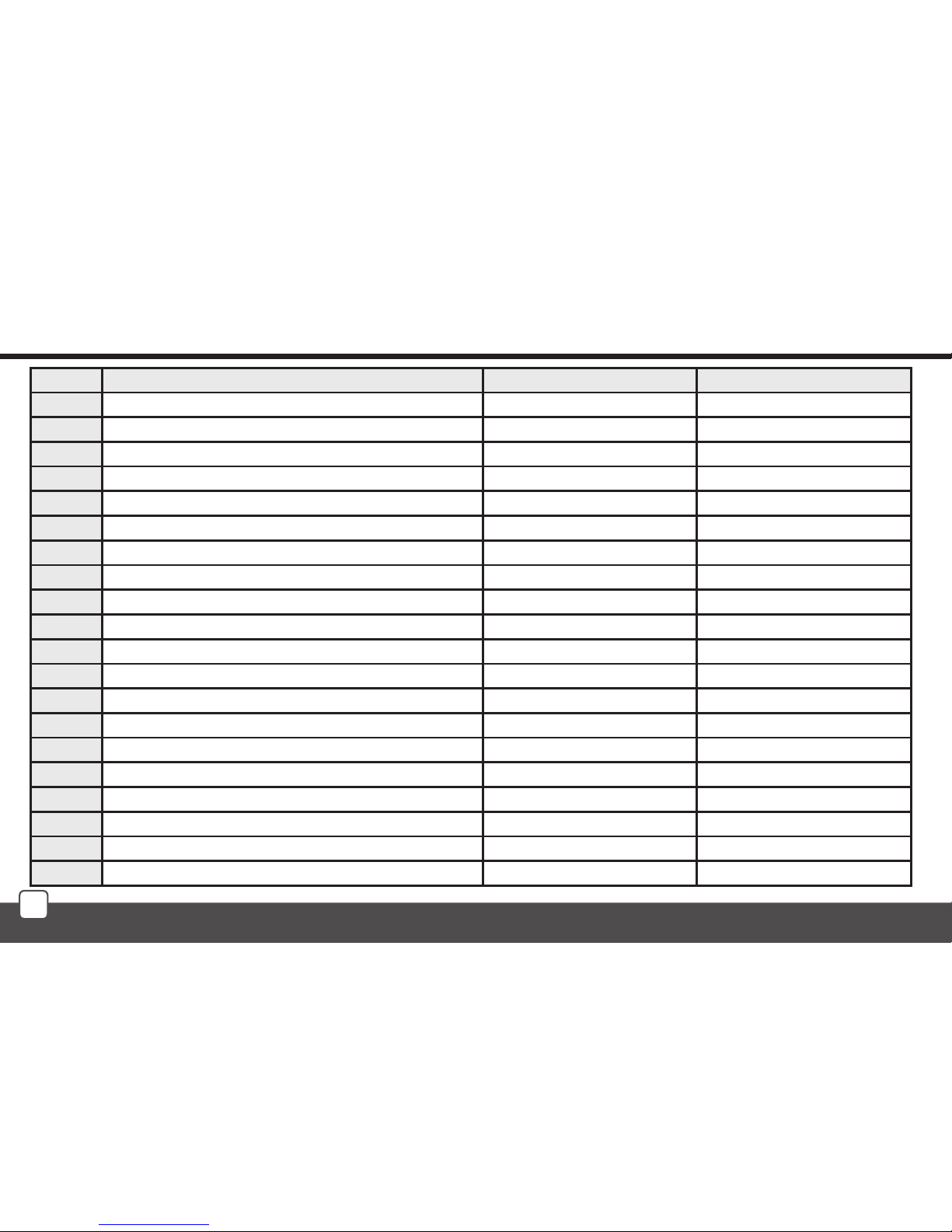
Number Description / name of the controlled device Actuator name Actuator address
Installation Form
Page 43
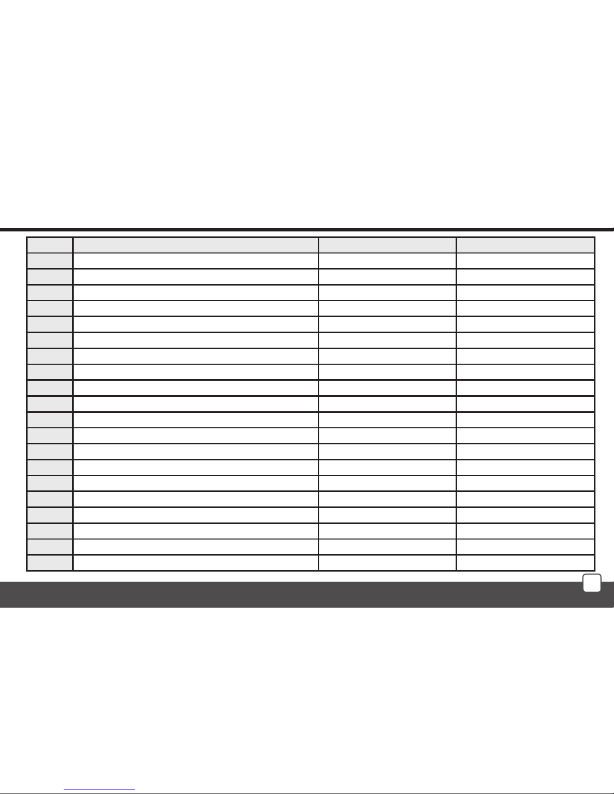
43
21.
22.
23.
24.
25.
26.
27.
28.
29.
30.
31.
32.
33.
34.
35.
36.
37.
38.
39.
40
Number Description / name of the controlled device Actuator name Actuator address
Installation Form
Page 44

ELKO EP, s.r.o.
Palackého 493 | 769 01 Holešov | Všetuly,CZ, Tel: +420 573 514 211 | Fax: +420 573 514 227
[email protected] | www.elkoep.com
rev.0
 Loading...