

Elko LIC-2 User Manual
1 / 2
LIC-2
02-70/2016 Rev.: 0
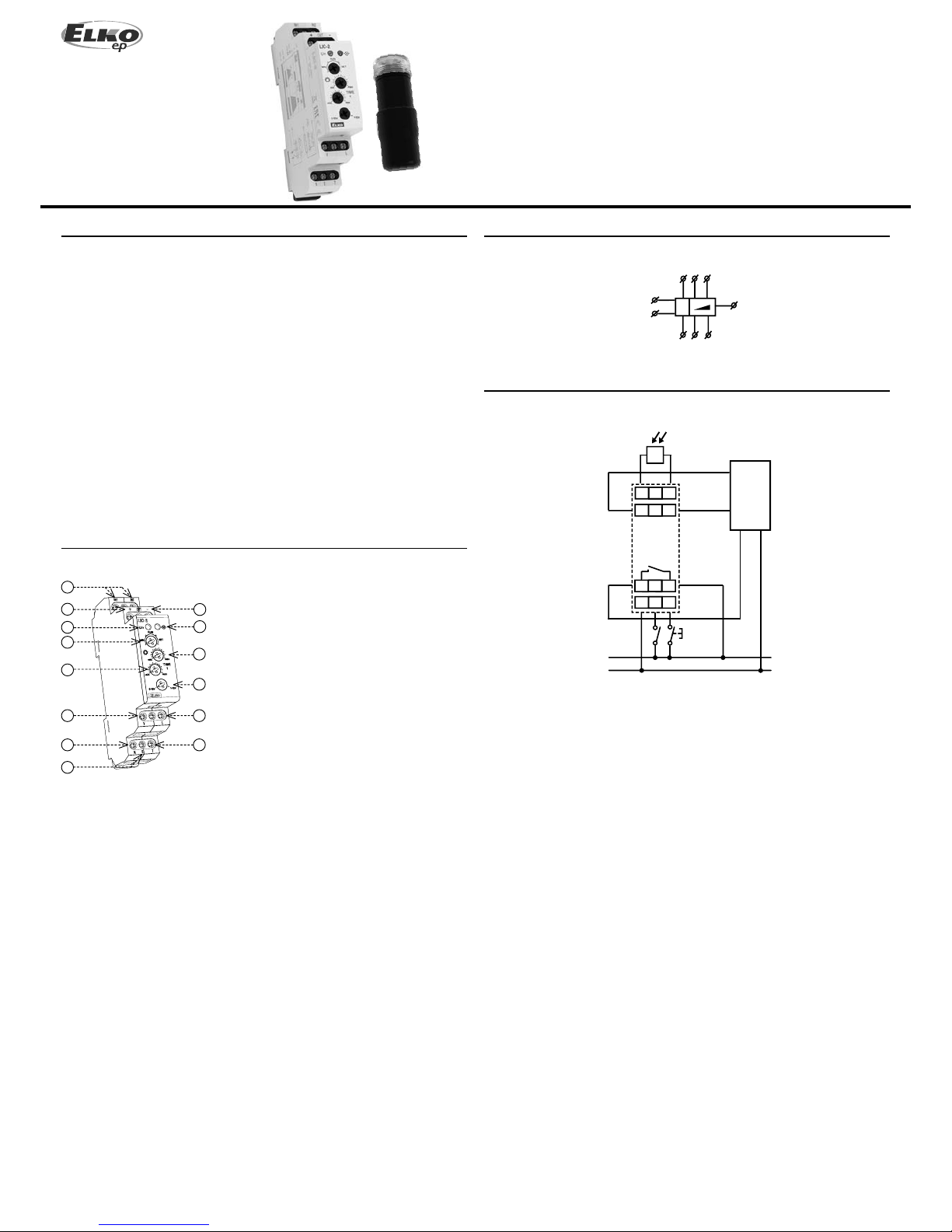
1
2
3
4
5
6
7
8
9
12
11
10
14
13
N
L
V
T
IN1
IN2
B
OUT-
OUT+
L
N
N B T
IN1 IN2
OUT+ OUT-
V L
+
–
L N
Made in Czech Republic
ELKO EP, s.r.o.
Palackého 493
769 01 Holešov, Všetuly
Czech Republic
Tel.: +420 573 514 211
e-mail: elko@elkoep.com
www.elkoep.com
Lighting intensity controller
Characteristics
Description
Symbol
Connection
EN
• serves as control unit for dimmers or electronic ballasts with analog control 0-10 V /
1-10 V
• keeps a preset lighting intensity (automatic regulation)
• control operating modes using existing button:
- switch OFF
- automatic regulation
- cleaning (maximum illumination level)
• setting the basic parameters of lighting is performed by potentiometers
- min. brightness of illumination
- maximum illumination level
- speed of dimming / illumination
• blocking the automatic control using external signal
• power supply AC 100 - 250 V
• 1-MODULE, DIN rail mounting
1. Inputs for illumination sensor
2. Analog output OUT (+)
3. Supply voltage indication
4. P1 - operating mode settings *
5. Speed of dimming / illumination **
6. Relay output
7. Supply voltage N
8. Blocking input B
9. Analog output OUT (-)
10. Output indication
11. P2 - brightness settings
12. Selection 0 -10V / 1-10V
13. Supply voltage L
14. Control input T
blocking
* MIN - setting of min. brightness level (e.g. so energy-saving lamps do not go out during
regulation).
RUN - automatic regulation of lighting (brightness is maintained at the set value and
regulated using an illumination sensor).
SET - setting of the required level of illumination for automatic regulation.
In position SET and MIN, the brightness level is set by potentiometer P2 (green LED also
ashes). If the required brightness level is attained, the trimmer P1 is set to the RUN
position. The brightness level is thereby set (green LED lights up permanently).
** if the level of brightness on P2 is set on maximum the range is 24...120s
lighting sensor
controlled
dimmer or
ballast
2 / 2
LIC-2
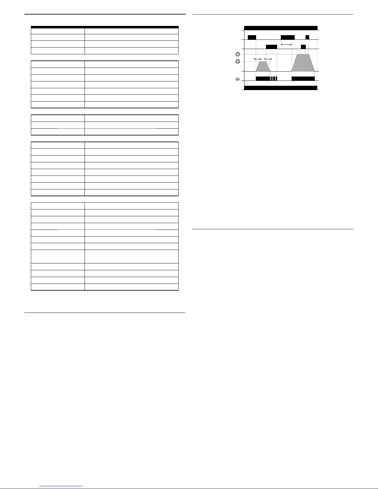
Un
T
B
max.
reg.
LED
LED Un
0.5-3s >3s <0.5s
3s
tt
Warning
Technical parameters Function
Control button functions
- Short press (<0.5s) - always switches o output (relay and output voltage).
- Longer press (0.5...3s) - runs automatic regulation of brightness level (according to
sensor).
- Long press (>3s) - sets the max. brightness level (CLEANING mode).
Blocking input function
- Switches o l igh tin g - o nly i n au tom ati c re gul atio n mo de ( has no i n uen ce in CLEANING
mode), e.g. for central switching o of lighting.
Output relay
- Switches on always upon switching on the lighting using the button if the DC output
voltage is greater than 0.1 V (for the mode 0-10 V) or 1 V (for the mode 1-10 V).
- Upon switching o the light, the relay opens if the output voltage drops below the
stated limits.
Red LED
- Illuminates upon active ouput (at any brightness level).
- Flashes upon activation of blocking.
Device is constructed for connection in 1-phase main AC and must be installed according
to norms valid in the state of application. Connection must be realized according to the
details in this instruction manual. Installation, connection, setting and operating should
be made by quali ed electrician sta only, who has learnt these instruction and functions
of the device. This device contains protection against over voltage peaks and disturbancies
in supply. For correct function of the protection of this device there must be a suitable
protections of higher degree (A, B, C) installed in front of them. Before installation the main
switch must be in position “OFF” and the device should be de-energized. Don´t install the
device to sources of excessive electro-magnetic interference. By correct installation ensure
ideal air circulation so in case of permanent operation and higher ambient temperature
the maximal operating temperature of the device is not exceeded. For installation and
setting use screw-driver cca 2 mm. The device is fully-electronic - installation should be
carried out according to this fact. Non-problematic function depends also on the way of
transportation, storing and handling. In case of any signs of destruction, deformation, nonfunction or missing part, don´t install and claim at your seller. After the product exceeds
lifetime, it should be removed and placed in protected dump.
Important instructions and cautions - dimmer is not designated for controlling of motors.
HDO warning signals and other similar signals spreaded by main, can cause interruption of
dimmer. Interruption is active only during transmitting of these signals.
Supply terminals:
Supply voltage:
Consumption apparent / loss:
Power supply indication:
Control
Button - control terminals:
Control voltage:
Impulse length:
Glow tubes connection:
Button - control terminals:
Glow tubes connection:
Duration of control pulse:
Output 1
Analog:
Terminals:
Galvanically separated:
Output 2
Number of contacts:
Current rating:
Switching capacity:
Peak current:
Switching voltage:
Output indication:
Mechanical life:
Electrical life (AC1):
Other information
Operating temperature:
Storage temperature:
Operating position:
Mounting:
Ingress protection:
Overvoltage category:
Contamination degree:
Connecting cond. cross-
section (mm
2
):
Dimensions:
Weight:
Weight of sensor SKS:
Standards:
L - N
AC 100 - 250 V / 50 - 60 Hz
max. 2.7 VA / 1.4 W
green LED
L - T
AC 100 - 250 V
min. 80 ms / max. unlimited
no
L - B
no
min. 80 ms / max. unlimited
0 - 10 V / 10 mA max. or 1 - 10 V / 10 mA max.
OUT+, OUT-
yes
1x NO (AgSnO
2
)
16 A / AC1
4000 VA / AC1, 384 W / DC
30 A / < 3 s
250 V AC1 / 24 V DC
red LED
3x10
7
0.7x10
5
-20 °C to +55 °C (-4 °F to 131 °F)
-20.. +60 °C (-22 °F to 140 °F)
any
DIN rail EN 60715
IP40 from front panel, IP20 terminals
III.
2
max. 1x 2.5, max. 2x 1.5,
with sleeve max. 1x 2.5 (AWG 12)
90 x 17.6 x 64 mm (3.5˝ x 0.7˝ x 2.5˝)
78 g (2.8 oz)
20 g (0.7 oz.)
EN 60669-2-1, EN 61010-1, EN 60929
Photosensor SKS
Sensor is external and is connected to terminals IN.
Sensor is insta llable to panel (by screw-a ble transparent cover) to openin g with diameter
16 mm. A part of the sensor is a plastic holder for placing into the wall or to another
place. Length of a line connector to the sensor cannot be more than 50 m. Doublecure
cable can be used as wire diameter min. 2x 0.35 mm
2
and max. 2x 2.5 mm2. Protection
degree is IP44.
It is possible to use photoresistor, which changes resistance in accordance with ambient
illumination, as a sensor. Tolerance sensor ± 33 %.
Installation ans setup of photosensor:
- sensor can not be installed nearby the windows and shouldn‘t be exposed to direct
sunlight (neither arti cial light)
- setting of desired level of illumination shoud be performed at a maximum darkness
(e.g. shutters down) to exclude in uence of any illumination from the outside
 Loading...