

Elko HRF-10 User Manual
1 / 2
HRF-10
cos φ ≥ 0.95
M M
HAL.230V
K
M M
AC12
250V / 1A
DC14
x
AC1
250V / 8A
AC13
x
AC2
250V / 3A
AC14
250V / 3A
AC3
250V / 2A
AC15
250V / 3A
AC5b
300W
DC5
24V / 2A
AC6a
x
DC12
24V / 8A
AC7b
250V / 1A
DC13
24V / 2A
02-15/2017 Rev.: 0
1
6
7
8
5
2
3
9
10
4
16 15 18 28 25 26
N L
L
N
DC1
24V / 8A
DC3
24V / 3A
Made in Czech Republic
ELKO EP, s.r.o.
Palackého 493
769 01 Holešov, Všetuly
Czech Republic
Tel.: +420 573 514 211
e-mail: elko@elkoep.com
www.elkoep.com
Frequency monitoring relay
• the relay serves to monitor frequency of AC voltage, e.g. in photovoltaic power
stations, generators
• the monitored frequency 50 / 60 / 400 Hz is selected by a switch
• supplied from monitored voltage
• two adjustable levels of frequency (Fmin, Fmax) in the range of 80 - 120 % Fn
• adjustable di erence level
• adjustable delay level
• switchable ranges of rated frequency Fn
• 3-MODULE design, DIN rail mounting
Characteristics
Description
Connection
Type of load
Mat. contacts AgNi,
contact 8A
Type of load
Mat. contacts AgNi,
contact 8A
AC5a
uncompensated
230V/1.5A (345VA)
AC5a
compensated
x
EN
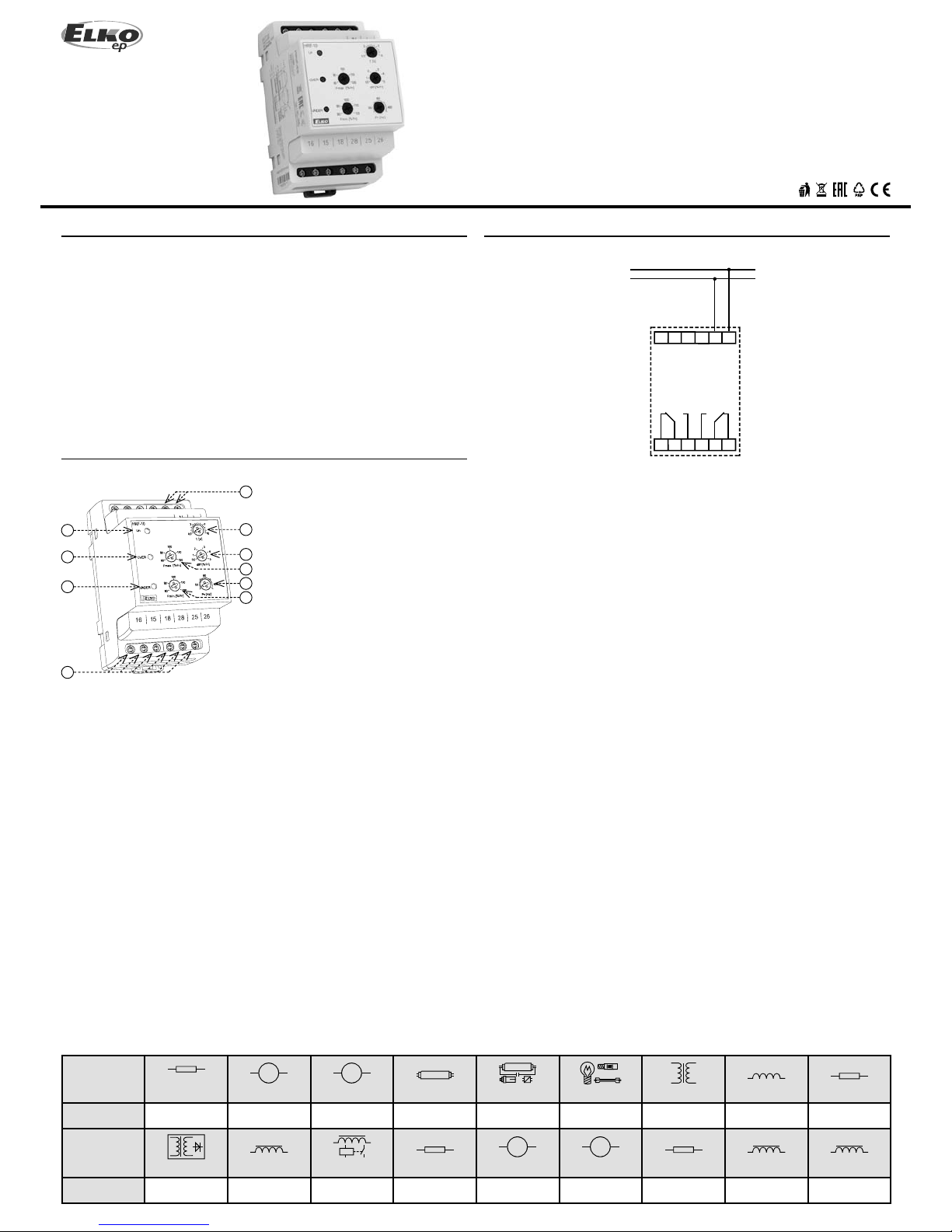
1. Supply voltage indication
2. Indication F > Fmax
3. Indication F < Fmin
4. Output contact
5. Supply / monitored voltage terminals
6. Delay setting
7. D i erence setting
8. Fmax setting
9. Fn setting
10. Fmin setting
2 / 2
HRF-10
Fmax
Fmin
25-28
15-18
OVER LED
UNDER LED
LED
t
t
t
Warning
Technical parameters
Device is constructed for connection in 1-phase main alternating current voltage and
must be installed according to norms valid in the state of application. Connection
according to the details in this direction. Installation, connection, setting and ser vicing
should be installed by quali ed electrician sta only, who has learnt these instruc tion
and functions of the device. This device contains protection against over voltage
peaks and disturbancies in supply. For correct function of the protection of this device
there must be suitable protections of higher degree (A , B, C) installed in front of them.
According to stan dards elimination of disturb ancies must be ensured. Bef ore installation
the main switch must be in position “OFF” and the device should be de-energized.
Don´t install the device to sources of excessive electro-magnetic inter ference. By correct
installation ensure ideal air circulation so in case of permanent operation and higher
ambient tempe rature the maximal operat ing temperature of the device is not e xceeded.
For installation and setting use screw-driver cca 2 mm. The device is fully-electronic installation should be carried out according to this fac t. Non-problematic function
depends also on the way of transportation, storing and handling. In case of any signs
of destruction, deformation, nonfunction or missing part, don´t install and claim at your
seller.
Function
Supply and monitoring terminals:
Supply voltage:
Rated frequency Fn:
Burden (max):
Overload capacity
- continuous:
- max. 10 s:
Frequency Fmax:
Frequency Fmin:
Di erence:
Delay (until failure):
Opening level (Uopen):
Output relay - contact:
AC contact cap acity:
DC contact capacit y:
Mechanical life:
Other information
Operating temperature:
Storage tem perature:
Electrical strenght
(supply - relay contact):
Protection degree:
Pollution d egree:
Protection degree:
Max. cab le size (mm
2
):
Dimensions:
Weight :
Standard s:
L, N
161 - 346 V
50 / 60 / 400 Hz
1.7 VA / 1.1 W
346 V
416 V
adjustab le 80 - 120 % Fn
adjustab le 80 - 120 % Fn
adjustab le 0.5 - 5 % Fn
adjustab le 0.5 - 10 s
161 V
2x changeove r / SPDT (AgNi) gilded
250 V / 8 A, max . 2000 VA
30 V / 8 A
3x10
6
at rated load
-20 °C to 55 °C (-4 °F to 131 °F)
-30 °C to 70 °C (-22 °F to 158 °F)
4 kV / 1 min.
III.
2
IP40 from font p anel / IP20 terminals
max. 2x 1.5 / 1x 2.5 (AWG 12)
90 x 52 x 64 mm (3.5 x 2 x 2 .6˝)
125 g (4.4 oz.)
EN 60255-6, E N 60255-27, EN 61000- 6-2, EN 6100 0-6- 4
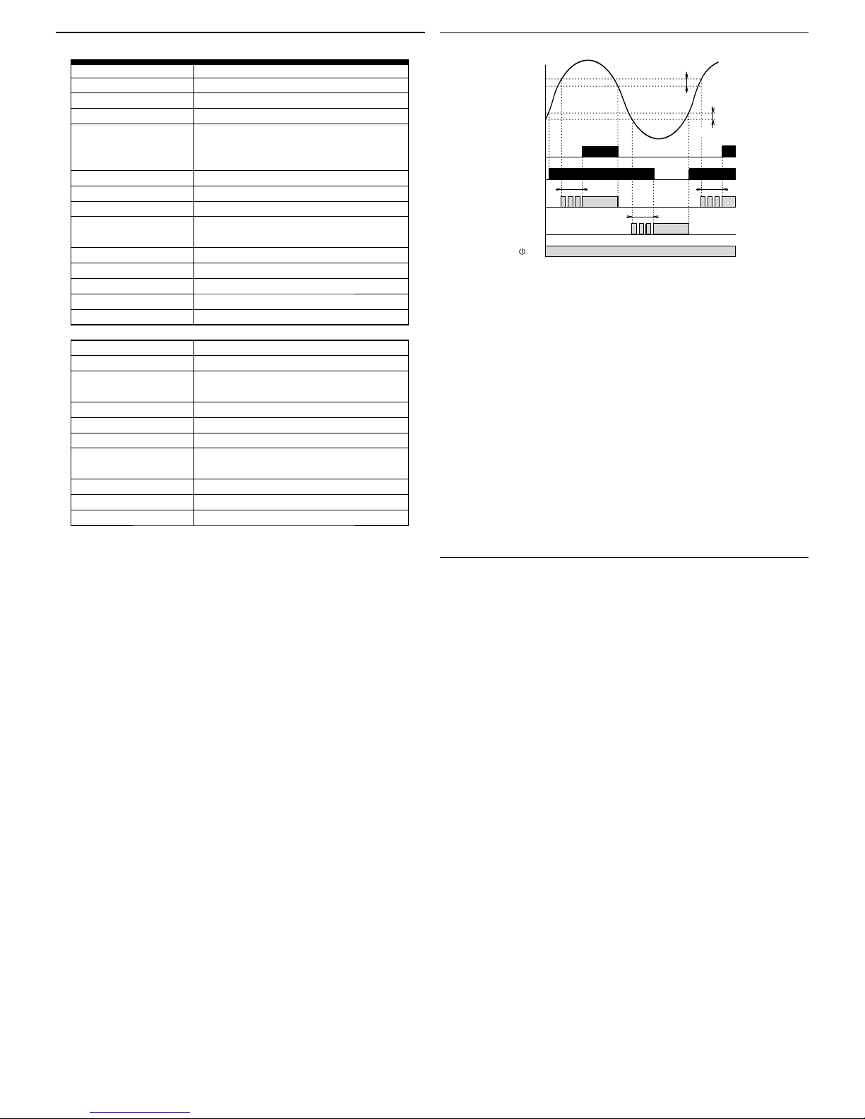
After the supply (monitored) voltage is connected, the green LED is on.
If the value of th e monitored frequenc y falls within the range be tween the two set levels
Fmin - Fmax no red LED is on. The relay UNDER is triggered (contacts 15-16-18) and the
relay OVER is disconnected (contacts 25-26-28).
If the monitored frequency exceeds the set level Fmax, the relay OVER is triggered after
the set delay timing elapses and the red LED OVER goes on. The red LED ashes during
the timing.
If the monitored frequency drops below Fmax - di erence, the relay is activated without
delay and the red LED OVER goes o .
If the monitored frequency drops below the set level Fmin, the relay UNDER is
disconnec ted after the set delay ti ming elapses and the red LED UN DER goes on. The red
LED ashes during the timing. If the monitored frequency exceeds the level Fmin + the
di erence, the relay is triggered without delay and the red LED UNDER goes o .
If the monitored voltage is lower than the opening level Uopen both the relays are
disconnected and both the red LED (UNDER and OVER) start ashing slowly - indicating
insu cient supply voltage.
di erence
di erence
 Loading...