

Elko EST3 User Manual
EST3
Control unit with touch screen
EN
ELKO EP, s.r.o. | Palackého 493 | 769 01 Holešov, Všetuly | Czech republic | e-mail: elko@elkoep.com
TECHNICAL SUPPORT | E-mail: support@inels.com | Mobil: +420 778 427 366 | Tel.: +420 573 514 276, +420 573 514 211 | Fax: +420 573 514 227 | www.inels.com
02-82/2017
Rev.0
12:30
A
e
1/4
Characteristics /
- The control unit with touch s creen EST3 is a suitable control element of th e iNELS system in
places where it is necessar y to control multiple devices. The uni t replaces several drivers and
enables minimizing the numb er of switches on the wall.
- EST3 features a 3.5 „color touc hscreen with an aspect ratio of 3:4. Th e basic display resolution is
240 x 320 pixels. The color depth of 16.7 millio n colors (24 bit color, True Color).
- Use the touch sensing surf ace to control confi gured buttons and symb ols on the screen just by
a light touch of a fi nger. Individual symbols on the screen are in the „Press “ animated by the associated output in the s ystem.
- EST3 can have a combination o f these screens:
- Buttons screen
- Temperature control screen
- Control RGB/RGBY/RGBW light sources scre en.
- Selecting the def ault screen is possible from the i DM3 software.
- For screen of buttons one of fo ur diff erent matrixes buttons can be used - 2 x2, 2x3, 3x3 and 3x4.
Matrix selectio n can be done from the iDM3 sof tware. On the screen c an then be used up to 12
buttons to control applia nces or scenes.
- In the menu settings, di rectly on the EST 3 component one of 48 prep ared symbols (for control o f
lighting, shading, scenes and oth er technologies) can be assi gned to each button or the b uttons
can be used to enter text (numb er of characters dep ends on the matrix of but tons and therefore
the size of the buttons).
- The temperature regulati on screen enables coordination of the temperature o f the selected
heating circuit in a range of ±3, ±4 or ± 5 °C (in relation to settings in iDM3).
- The virtual whee l can be used for temperature cor rection, where you can dr ag your fi nger across
the screen to control the tempe rature by half a degree Celsius.
- The temperature correc tion can also be used instead o f the virtual wheel sy mbols „+ „ and „- „ .
- EST3 units do not have an inte grated temperature sensor, or terminals fo r connection to an external temperature sensor. Wi thin the iDM3 software, it is possible to assi gn any unit of heat
input system iNELS.
- The control RGB/RGBY/RGBW light sources s creen allows you to comfortably cont rol your RGB/
RGBY/RGBW light sources and adjust the luminous atm osphere as needed.
- For these RGB/RGBY/RGBW light sources , it is p ossible to use the controls on the sc reen to adjust
the color and brightness . It is also possible to directl y set the RGB/RGBY/RGBW illumination light
source into white color.
- Located in the left up per corner of the screen are 4 indicator s that can signal the status of any
logical input / outpu t in the iNELS system.
- In iDM3 it is possible to defi ne the displayed screen, the default screen, mat rix of buttons, type
RGB/RGBY/RGBW and a correctio n range for the temperature co ntrol.
- In the settings menu directly on the device EST3 it is possible to select the menu language,
screen saver, sleep mode, bright ness adjustment and symbols a nd texts for each button .
- EST3 are designed as LOGUS
90
devices (EST3 however ca nnot be placed into multi-frames wi th
other devices in this design) and are inte nded for mounting to installati on box.
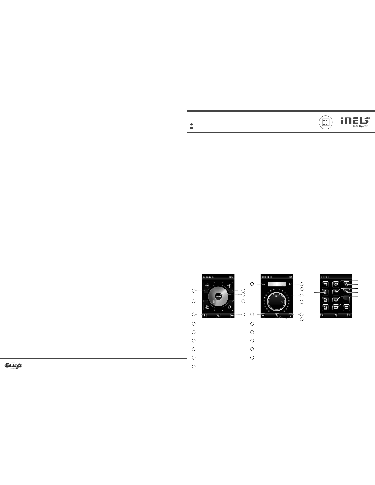
The screenshots /
1
4
5
6
8
Decrease brightness /
Illumination in color based on RGB /
Increase brightness /
Device Information /
2
3
10
7
9
Output ON/OFF button /
Button for moving between screens /
Illumination in white /
Circuit temperature adjustment /
Current temperature /
Current temperature /
1
2
3
0 %
IN1
IN4
IN7
IN10
IN3
IN6
IN9
IN12
IN2
IN5
IN8
IN11
+ 20.5 °C
20.5 °C
4
5
6
787
8
8
10
3
9
Legend:
EST3 => settings menu => design s election => 2x2 - input I N1- IN4
EST3 => settings menu => design s election => 2x3 - input IN1- IN6
EST3 => settings menu => design s election => 3x3 - input IN1- IN9
EST3 => settings menu =>design s election => 3x4 - input IN1- IN12
11
10
Settings /
4/4
Warning /
Before the device is ins talled and oper ated, read this instr uction manual c arefully and wit h full underst anding and
Installation Guide Sy stem iNELS3. The instru ction manual is desig nated for mounting the de vice and for the user
of such device. It has to be attached to electro-installation documentation. The instruction manual can be also
found on a web site www.i nels.com. Attention, dan ger of injury by elect rical current! Mounting a nd connection
can be done only by a pro fessional with an ade quate electric al qualifi cation, and all has to be done while o bserving valid regulation s. Do not touch parts o f the device that are energ ized. Danger of life -threat! While mountin g,
servicing, exe cuting any changes, an d repairing it is essent ial to observe safe ty regulations, n orms, directive s and
special regulatio ns for working with el ectrical equi pment. Before you st art working wit h the device, it is essenti al
to have all wires, connec ted parts, and terminals de- energized. This instruc tion manual contains only general
directions which n eed to be applied in a parti cular installation. In the cour se of inspections and mainte nance,
always check (while de -energized) if ter minals are tightened.
SK
Ovládacia jednotka s dotykovým displejom
ELKO EP SLOVAKIA, s.r.o. | Benkova 18 | 949 11 Nitra | Slovenská republika
Tel.: +421 37 6586 731 | e-mail: elkoep@elkoep.sk | www.elkoep.sk
Charakteristika
- Ovládacia jednotka s do tykovým displejom EST 3 je vhodným ovládacím prvk om systému iNELS
v miestach, kde je požadov ané ovládanie viacerých zaria dení. Jednotka nahrádza n iekoľko ovládačov a umožňuje tak minimalizovať počet v ypínačov na stene.
- EST-3 disponuje 3.5“ farebným dotykov ým displejom v pomere strán 3:4. Základné rozlíšeni e
displeja je 240 x 320. Farebná hĺbka je 16.7 miliónov farieb (24 bitová fa rba, True Color).
- Pomocou snímacej dotykovej plo chy je možné ovládať nakonfi gurované tlačidlá a symboly na
obrazovke obyčajným ľahkým dotykom prsta. Jednotlivé symboly na obrazovke sú pri „stlačení“
animované podľa prirad eného výstupu v sys téme.
- EST3 môže disponovať kombiná ciou týchto obrazoviek:
- Obrazovka tlačidiel
- Obrazovka regulácie tep loty
- Obrazovka ovládania RGB/ RGBY/RGBW svetelných zdrojov.
- Voľba defaultnej obra zovky je možná zo softvé ru iDM3.
- U obrazovky tlačidie l je možné využiť jednu zo šty roch rôznych matíc tlačidiel - 2x2, 2x3, 3x 3 a
3x4. Voľbu matice je možné vyko nať zo softvéru iDM3. Na obrazovke možn o teda využiť až 12
tlačidiel na ovládanie dvanás tich spotrebičov alebo scén.
- V menu nastavenia priamo na jedn otke EST3 možno jednotlivým tl ačidlám priradiť jeden zo 48
pripravených symbolov (na ovlá danie osvetlenia, tienenia, scén a ďalších te chnológií) alebo do
tlačidla vpísať text (p očet znakov podľa zvolenej m atice a teda veľkosti tlačidiel ).
- Obrazovka regulácie tep loty umožňuje korigovať teplotu zvoleného v ykurovacieho okruhu v
rozsahu ±3, ±4 alebo ±5 °C (v záv islosti na nastavení v iDM3).
- Pre korekciu teploty možno v yužiť virtuálne koliesko, ked y je možné ťahaním prsta po ob razovke
regulovať teplotu po pol s tupňoch Celzia.
- Na korekciu teploty je možné tie ž použiť namiesto virtu álneho kolieska symboly „+“ a „-“.
- Jednotky EST3 n emajú integrovaný teplotný senzor ani svorky pre pr ipojenie externého teplotného senzoru. V rámc i softwaru iDM3 je možné jednotke p riradiť ľubovolný teplotný vstup
systému iNELS.
- Obrazovka ovládania RGB/ RGBY/RGBW svetelných zdrojov dovoľuje užívateľovi veľmi komfor tne
ovládať svoje RGB/RGBY/RGBW svetelné zdroje a u pravovať si svetelnú atmosféru p odľa potreby.
- U RGB/RGBY/RGBW svetelných zdrojov možno pom ocou ovládacích prvkov na obra zovke upravovať požadovanú farbu a j as. Tiež možno priamo nas taviť rozsvietenie RGB/ RGBY/RGBW svetelného zdroja do bielej farby.
- Na obrazovke sú v ľavom hornom rohu u miestnené 4 indikátory, ktoré môžu signali zovať stav
ktoréhokoľvek logick ého vstupu / výstupu v s ystéme iNELS.
- V iDM3 je možné defi novať zobrazované obrazov ky, defaultnú obrazovku, maticu tlačidiel, t yp
RGB / RGBY / RGBW a korekčný rozsah na ovláda nie teploty.
- V menu nastavenia priamo na jednot ke EST3 je možné voliť jazyk me nu, šetrič obrazovky, režim
spánku, nastavenie jasu a symb oly, popr. texty pre jednotlivé tla čidlá.
- EST3 je designovo koncipovaná do rady prístrojov LOGUS
90
(EST3 však nemožno nás obiť do viac-
rámčekov s ostatnými príst rojmi v tomto designe) a je určená pre montáž do i nštalačnej krabice.
Ukážka obrazoviek
Znižovanie jasu
Rozsvietenie do farby podľa RGB
Zvyšovanie jasu
Info o zariadení
Tlačidlo zapnutia / vypnutia výstupu
Tlačidlo pre pohyb medzi obrazovkami
Rozsvietenie do bielej
Korekcia teploty okruhu
Požadovaná teplota
Aktuálna teplota
Legenda:
EST3 => menu nastavenia => voľba pre dlohy => 2x2 - vstup IN1- IN4
EST3 => menu nastavenia => voľba pre dlohy => 2x3 - vstup IN1- IN6
EST3 => menu nastavenia => voľba pre dlohy => 3x3 - vstup IN1- IN9
EST3 => menu nastavenia => voľba pre dlohy => 3x4 - vstup IN1- IN12
Nastavenie
Varovanie
Pred inštaláciou prístroja a pred jeho uvedením do prevádzky sa dôkladne zoznámte s montážnym návodom
na použitie a inštal ačnou príručkou systému iNELS3. Návo d na použitie je určený pre montáž príst roja a pre
užívateľa zariaden ia. Návod je súčasťou dokumentá cie elektroinštalácie, a ti ež k stiahnutiu na webovej strá nke
www.inels.sk . Pozor, nebezpečie úra zu elektrick ým prúdom! Montáž a p ripojenie môžu v ykonávať len pracovn íci
s príslušnou odbornou elektrokvalifi káciou pri dodržaní platných predpisov. Nedotýkajte sa častí prístroja, ktoré
sú pod napätím. Nebez pečie ohrozenia života. Pri montáži , údržbe, úpravách a opravách je nu tné dodržiavať
bezpečnostn é predpisy, normy, smernice a odborné ustanoven ia pre prácu s elektrickým zariad ením. Pred
zahájením práce na pr ístroji je nutné, aby všetk y vodiče, pripojené diel y a svorky boli bez nap ätia. Tento návod
obsahuje len všeob ecné pokyny, ktoré musia b yť aplikované v rámci dan ej inštalácie. V rámci kontro ly a údržby
pravidelne kontrolujte ( pri vypnutom napá janí) dotiahnutie s voriek.
EST3
2/4
Technical parameters /
3/4
General instrucions /
CONNECTION INTO THE SYSTEM
Connect the produc t to the system according to the co nnection diagram liste d with each
product. The wires o f data BUS of iNELS system are connecte d to the terminals BUS + (standard
red wire for single-pair w iring, red and yellow for two-pair w iring) and BUS- (standard black wire
for single-pair wirin g, black and white for two-pair wirin g), and it is not possible to change the
terminals. A twisted pa ir of wires must be used for the data BUS with a w ire diameter at least 0.8
mm. Data communications and p ower supply to the units are led in a single pair of wires , and
you must observe the p ower cable size with regard to volta ge loss on the wire and the maxim um
power draw.
CAPACITY AND CEN TRAL UNIT
It is possible to connec t to the central unit CU3-01M or CU3-02M two independent BUSes BUS
by means of terminals BUS1+, BUS1- and BUS2+, BUS2-. It is possible to connect to each B US up to
32 units, so it is possible to connect directly to the central unit a total of 64 units. It is necessary
to comply with the requireme nt of a maximum load of one BUS line – maximum up to 100 0mA
current. It is the sum of the rated c urrents of the units connecte d to the BUS line, other units can
be connected using th e units MI3-02M, which generate fur ther BUSes. These are connected to
the CU3 unit via the system BUS EBM and you c an connect a total of 8 units via EBM BUS to the
central unit MI3-02M .
COMMUNICATION BUS O F THE SYSTEM
The BUS must have a cable created by a t wisted pair of wires for data BUS of the system with
a minimum wire diameter of 0.8 mm. A shield ed cable must be used in case of installation of
cables of the BUS in an environm ent with the possibility of electromag netic interference (e.g.
when running along power li nes, near electric machin es and devices, during LV passage throug h
a distributor, etc.). We highly recommend usin g the cable JYSTY 2x2x0. 8 for BUS. The BUS cable
is installed in accordance wit h its mechanical properties g iven by the producer (into a pipe/bar,
under plaster, underground, suspended, etc.) To increase the mechanical resistance of cables,
we always recommend installing the cable into an electrical insulation pipe of the appropriate
diameter. The total length of wire s of the BUS for CU3-01M (CU3-02M), or MI3-02M, can be 1,100
m (550 m for each BUS). The topology of the com munications BUS is open with the excepti on of
topology of the circui t. It is necessary to use th e cable FTB CAT5e or higher for t he system BUS EBM
– one pair of wires is connec ted to the terminals EBM+ and EBM- an d the second pair of wires can
be curled and connec ted to GND terminal (just on the o ne side of EBM BUS). The typolo gy of EBM
system BUS is strictly linear and must be terminated at both ends with a nominal resistance value
of 120Ω. It is the installer‘s responsibili ty to follow all instructi ons in the manual and all installation
requirements for the RS4 85 BUS.
SUPPLYING THE SYSTEM
For supplying power to sy stem units, it is possible to us e the power sources of ELKO EP title d PS3100/iNELS. We recommend bac king up the system wi th backup batterie s connected to the so urce
of PS3-100/iNELS (see sample diagr am of connecting the contro l system).
GENERAL INFORMATION
To operate the unit, it is necess ary that the unit is conn ected to a central unit CU3 se ries, connecte d
to the central unit of the sys tem CU3, or to a system that already contains t his unit as its expansion
to include further s ystem.
All unit parameters are set t hrough the central unit CU3 in the sof tware iDM3.
There is LED diode on the PCB for in dication of supply voltage and communication wit h the
central unit series CU3. In case that t he RUN diode fl ashes at regular intervals , so there is standard
communication betwe en the unit and BUS. If the RUN diode lights permane ntly, so the unit is
supplied from BUS, but there is no co mmunication between BUS and u nit. In case that RUN diode
is OFF, so there is no supply voltage on the termina ls BUS+ and BUS-.
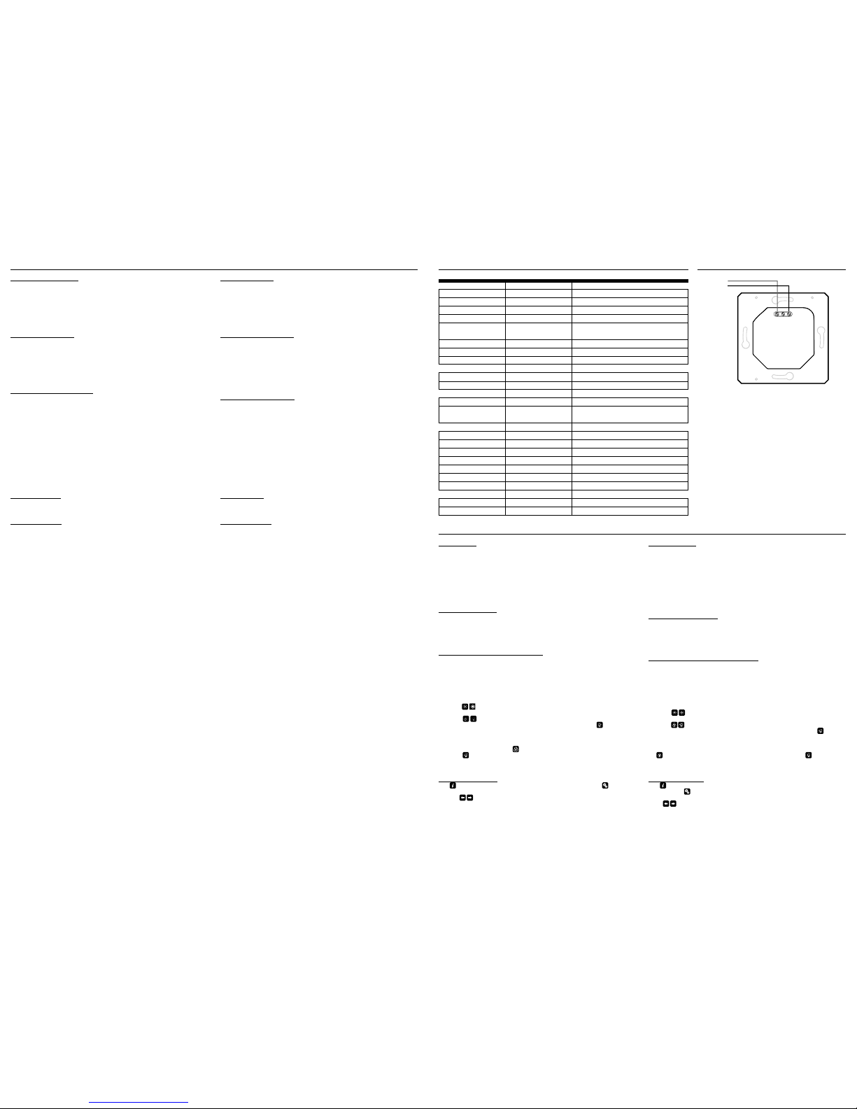
Connection /
Display
Type:
Aspect ratio:
Visible area:
Backlight:
Touch pa d:
Display:
Number of points:
Color Depth:
Power supply
Supply voltage / toleran ce:
Rated current:
Connection
Connection:
Connecting conductors
pro le:
Operating conditions
Operating temperature:
Storing temperat ure:
Protection degree:
Overvoltage categ ory:
Pollution degre e:
Operating positi on:
Installation:
Dimensions and weight
Dimensions:
Weight:*
BUS
BUS
+
-
EST3
BUS+ BUS-
* Weight is listed with plastic frame.
Function /
BUTTONS SCREEN
- Programming iNELS syste m functions on each button on the scre en units EST3 is the same as
programming other digita l inputs or events for input or bu tton units.
- Buttons can be confi gured as well as other inputs in the system, both for shor t and also long
press (> 1.5 s).
- Buttons (icons) on the screen can b e used instead of control outputs for v isualization of one of
the digital outputs o f the system iNELS. This is ma de possible by assigning but ton to the desired
output.
- In doing so, the button (icons) on th e screen EST3 will becom e signal lamps (illuminated button),
showing the state of the asso ciated output.
HEATING CONTRO L SCREEN
- On the temperature control s creen, the temperature of the sele cted heating circuit can be corrected in the range of ±3, ±4 o r ±5 °C.
- The virtual whee l can be used for temperature cor rection, where you can dr ag your fi nger across
the screen to control the tempe rature by half a degree Celsius.
- The temperature correc tion can also be used instead o f the virtual wheel sy mbols "+ " and "- " .
RGB LAMP AND LI GHT SOURCE CONTR OL SCREEN
- The RGB light sources control sc reen contains controls for managing th e desired color and
brightness of the RGB light so urces.
- RGB control screen func tion is set up so that the colors R, G , B are bound together and simulate
the signal level on analog inpu ts R, G, B and the resulting brightness of th e lamp is linked to a
simulated analog input 0 to 100% .
- The RGB control display is compris ed of several elements and bu ttons.
- A long press (touch) on the ON/OFF cont rols the central setting o f RGB components and lamp
brightness - on/off .
- Buttons
in the upper half of the scre en are for setting the lamp bri ghtness from 0-100%
in 5% increments (see adjustab le brightness indicator in %).
- Buttons
in the lower half o f the screen are for setting the color co mfort and acceler-
ated lamp RGB control. The but tons have a lock function. Wh en pressing
"white illumination“ button, the analo g inputs are automaticall y set to the maximum value of in dividual color
components, which app ears as a resulting white light at the RGB light source output w hen
these components are mixe d. Then simply adjust th e brightness intensity at th e output. When
pressing (touching) the button
"RGB-based colo r illumination“, the "white illumination“,
button
automatically unlock s, and the "RGB-based color illumination“ set tings button
locks ..Now the values of analog in puts of i ndividu al RGB colo r compon ents are p reset acco rding to the set cursor in the col or wheel of the RGB scale on t he EST3.
ADDITIONAL INFORMATION
- Info
gives information on the device a nd fi rmware version. Clicking the icon br ings you to
the settings menu, use d to edit the EST3.
- The icon
returns to the buttons pan el.
- The system time is displaye d in the upper right corner of the s creen.
- In the case of request for ch anging the original screen (pan el) buttons, it is always necess ary to
perform RESET o f the device before confi guration of icons (buttons).
- All inputs and output s on the EST3 unit can be fre ely programmed and par ameterized using the
iDM3 program.
Technické parametreVšeobecné inštrukcie
PRIPOJENIE DO SYSTÉMU
Výrobky pripája jte do systému podľa schémy zapojenia uveden ej pri každom výrobku. Vodiče
dátovej inštalačnej zbernice BUS s ystému iNELS sa na jednotke prip ájajú do svoriek BUS+
(štandardne červený vodi č pre jedno-párové zapojenie, pre dvoj-p árové červený a žltý) a BUS(štandardne čierny vodič pre j edno-párové zapojenie, pre dvoj- párové zapojenie čierny a biely),
pričom nie je možné svork y vzájomne zameniť. Pre dátovú z bernicu je nutné použiť krú tený pár
vodičov s priemerom žíl najme nej 0.8 mm. Dátová komunikácia i napája nie jednotiek sú vedené v
jednom páre vodičov, a preto je nutné do držať priemer vodičov pre napájacie vo diče s ohľadom
na úbytok napätia na vedení a ma ximálny odoberaný výkon .
KAPACITA A CENTRÁLNA JEDNOTKA
K centrálnej jednotke CU3-01M alebo CU3-02M možno p ripojiť dve samostatné z bernice BUS
prostredníctvo m svoriek BUS1+, BUS1- a BUS2+, BUS2-. Na každú zbernicu možno pripoji ť až 32
jednotiek, celkovo možno teda priamo k centrálnej jednotke pripojiť až 64 jednotiek. Ďalej je
nutné dodržať požia davku na maximálne zaťažen ie jednej vetvy zb ernice BUS prúdom maximá lne
1000 mA, ktorý je daný súč tom menovitých prúdov j ednotiek pripojených na túto ve tvu zbernice.
V prípade potreby je možn é ďalšie jednotky pripo jiť pomocou externýc h masterov MI3-02M, ktoré
generujú ďalšie dve vetv y BUS. Tieto externé mastery s a pripájajú k jednotke CU3 cez systémovú
zbernicu EBM a celkom je možné ce z EBM zbernicu k centrálnej jednotke pripo jiť až 8 jednotiek
MI3-02M.
KOMUNIKAČNÁ ZBERNICA SYSTÉMU
Zbernica musí byť tvo rená káblom, ktor ý je tvorený krúteným páro m vodičov pre dátovú zbernicu
systému s minimálnym priem erom vodičov 0.8 mm. Tienený kábel je nutné použiť v p rípade
inštalácie káblov zb ernice do prostredia s možnosťou elektromagne tických interferencií (napr.
pri súbehu so silovým ved ením, v blízkosti elektric kých strojov a prístrojov, pri precho de NN
rozvádzačom apod ). Pre inštalačnú zbernicu BUS je odpor účaný kábel JYSTY 2x 2x0.8. Zbernicový
kábel sa inštaluje v súla de s jeho mechanick ými vlastnosťami, k toré udáva výrob ca (do trubky/lišt y,
pod omietku, do zeme, závesný ap od.). Pre zvýšenie mechanickej od olnosti káblov odporúčame
vždy kábel inštalovať d o elektroinštalačnej trubky vhodného pri emeru. Celková dĺžka vedenia
zbernice pre CU3-01M (CU3-02M), poprípade MI3- 02M, môže byť 1100 m (550 m pre každú
zbernicu). Topológia komunikačn ej zbernice BUS je voľná s výnim kou topológie kruhu. Sys témová
zbernica EBM musí byť t vorená káblom FTP CAT5e a vyššie, pričom je den pár vodičov sa pripája
na svorky EBM+ a EBM- a druhý p ár sa v prípade potreby stočí a pripojí na svo rku GND (iba na
jednej strane zbern ice EBM). Topológia systémovej zbernice EBM je prísne líniová a musí b yť na
oboch koncoch ukončená od porom s menovitou hodnotou 120Ω. Obe cne je nutné pri inštalácii
systémovej zbernice EBM db ať na všetky požiadavk y na inštaláciu zbernice RS 485.
NAPÁJANIE SYSTÉMU
Na napájanie jednotiek sy stému je možné použiť napájacie zdro je spoločnosti ELKO EP s názvom
PS3-100/iNELS. Odporúčame sy stém zálohovať externými akumulátor mi, pripojenými ku zdroju
PS3-100/iNELS (viď vzorová schéma zap ojenia riadiaceho systému).
VŠEOBECNÉ INFORMÁCIE
Pre funkciu jednotky je nutné, aby jednotka bola napojená na centrálnu jednotku systému rady CU3,
alebo na systém, kto rý túto jednotku už obsa huje, ako jeho rozšírenie o ďalšie funkc ie systému.
Všetky parametre j ednotky sa nastavujú cez ce ntrálnu jednotku rady CU3 v sof tware iDM3.
Na základnej doske jednot ky je LED dióda pre indikáciu napájacieho napätia a komu nikáciu s
centrálnou jednotkou rad y CU3. V prípade, že dióda RUN bliká v pravid elnom intervale, prebieha
štandardná komunikácia. Ak dióda RUN trvale svieti, je jednotka zo zbernice napájaná, ale
jednotka na zbernici n ekomunikuje. V prípade, že dióda RUN nes vieti, nie je na svorkách BUS+ a
BUS- prítomné napájacie na pätie.
Zapojenie
Displej
Typ:
Pomer strán:
Viditeľná plocha:
Podsvietenie:
Dotyková plocha:
Uhlopriečka:
Počet bodov:
Hĺbka farieb:
Napájanie
Napájacie napätie/ tolerancia:
Menovitý prúd:
Pripojenie
Pripojenie:
Prierez pripojovacích
vodičov:
Provozní podmínky
Pracovná teplota:
Skladovacia teplota:
Krytie:
Kategória prepätia:
Stupeň znečiste nia:
Pracovná poloha:
Inštalácia:
Rozmery a hmotnosť
Rozmery:
Hmotnosť:*
colored / farebný TF T LCD
3:4
52.5 x 70 mm
active / aktívne
4-wire resistive /
rezistívna 4 vodičová
3.5”
240 x 320
16.7M (24 bit color / 24 bitová farba)
27 V DC, -20 / +10 %
150 mA (at / pri 27V DC)
terminals / svorkovnica
max. 2.5 mm
2
/1.5 mm2 with sleeve / s dutinkou
0 .. +55°C
- 20 .. +70°C
IP20
II.
2
any / ľubovoľná
installation box / do in štalačnej krabice
94 x 94 x 36 mm
127 g
* s plastovým rámčekom
Všeobecné inštrukcie
OBRAZOVKA TLAČIDIEL
- Programovanie funkcií sys tému iNELS na jednotlivé tlačidlá na o brazovke jednotiek EST 3 sa vykonáva rovnako ako programovanie i ných digitálnych vstupov alebo udalos tí pri vstupných popr.
tlačidlových jednotiek.
- Tlačidlá je možné konfi gurovať rovnako ako iné vstupy v systéme a to ako pre kr átke, tak i dlhé
stlačenie (> 1.5 s).
- Tlačidlá (ikony) na obrazovke možn o namiesto ovládania výstupov v yužiť pre vizualizáciu stav u
niektorého z digitálnych v ýstupov systému iNELS. Toto je umožnené p riradením tlačidla k požadovanému výstupu.
- Týmto sa stanú tlačidlá (ikony) na obr azovke EST3 signálkami (presvi etenie tlačidla) stavu priradeného výstupu.
OBRAZOVKA REGUL ÁCIE TEPLOTY
- Na obrazovke regulácie tepl oty je možné korigovať teplotu zv oleného vykurovacieho ok ruhu v
rozsahu ±3, ±4 alebo ±5 °C.
- Pre korekciu teploty možno v yužiť virtuálne koliesko, ked y je možné ťahaním prsta po ob razovke
regulovať teplotu po pol s tupňoch Celzia.
- Ku korekcii teploty možno tie ž použiť namiesto virtuá lneho kolieska symboly „+“ a „-“.
OBRAZOVKA OVLÁDANIA RG B SVETELNÝCH ZDROJOV
- Obrazovka ovládania RGB s vetelných zdrojov obsahuje ovládacie prv ky pre riadenie požadovanej farby a jasu RGB svetelných zdrojov.
- Funkcia obrazovky ovládania RG B je nastavená tak, že jednot livé farebné zložky R , G, B sú zviazané
a simulujú úroveň signálu na analógových v stupoch R, G, B a výsledný jas svietid la je spätý a
simulovaný na analógovom vstu pe 0 - 100 %.
- Ovládacia obrazovk a RGB sa skladá z niekoľkých pr vkov a tlačidiel.
- Dlhým stlačením (dotykom) na tlači dlo ON/OFF sa ovláda centrálne nastavenie zlož iek RGB a
jasu svietidla - zapnuté /vypnuté.
- Tlačidlá
v hornej polovici obra zovky majú funkciu nastavenia jasu s vietidla od 0-100% v
kroku 5% (viď ukazovateľ nastav iteľného jasu v %).
- Tlačidlá
v dolnej polovici obrazovky majú funkciu nastavenia farebnej pohody a zrýchle-
ného ovládania RGB svieti dla. Tlačidlá majú funkciu aretácie. Pr i stlačení tlačidla
„rozsvietenie do bielej“ sa automatick y nastavia analógové vstupy d o maximálnej hodnoty jedn otlivých
farebných zložiek. Toto zmiešanie vš etkých zložiek sa prejaví rozsvieten ím svetelného zdroja
do bielej farby. Potom s a už koriguje len inte nzita jasu na výs tupe. Pri stlačení (do tyku) tlačidla
„rozsvietenie do f arby podľa RGB“ sa automaticky o dblokuje tlačidlo „rozsvi etenie do
bielej“ a tlačidlo nastaven ia „rozsvietenie do far by podľa RGB“ sa zaaretuje. Teraz sa p rednastavia hodnoty analógov ých vstupov jednotlivých farebných zložiek RGB po dľa nastaveného
kurzoru vo farebnom kolies ku stupnice RGB na obrazovke EST 3.
DOPLŇUJÚCE INFORMÁCIE
- Info
udáva informácie o zaria dení a verzii fi rmwaru.
- Pomocou ikony
prejdeme do menu Nastavenia, ktoré slúži na editáciu EST3 (heslo pre vstup
do Nas t ave ni a j e d ef au lt ne 1111 ).
- Ikony
vracia späť na panel tlačidie l.
- V pravom hornom rohu obra zovky je umiestnený systém ový čas.
- V prípade požiadavk y na zmenu predlohy obrazovk y (panelu) tlačidiel, je nutné v ždy pred konfi guráciou ikon (tlačidiel) v ykonať RESET zariadenia.
- Všetky vstupy a v ýstupy jednotky EST3 možn o voľne programovať a parametrizovať p omocou
programu iDM3.
 Loading...